2-D Transformation and Projection 2-D Drawing 26...
32
Transcript of 2-D Transformation and Projection 2-D Drawing 26...

Projection Theory
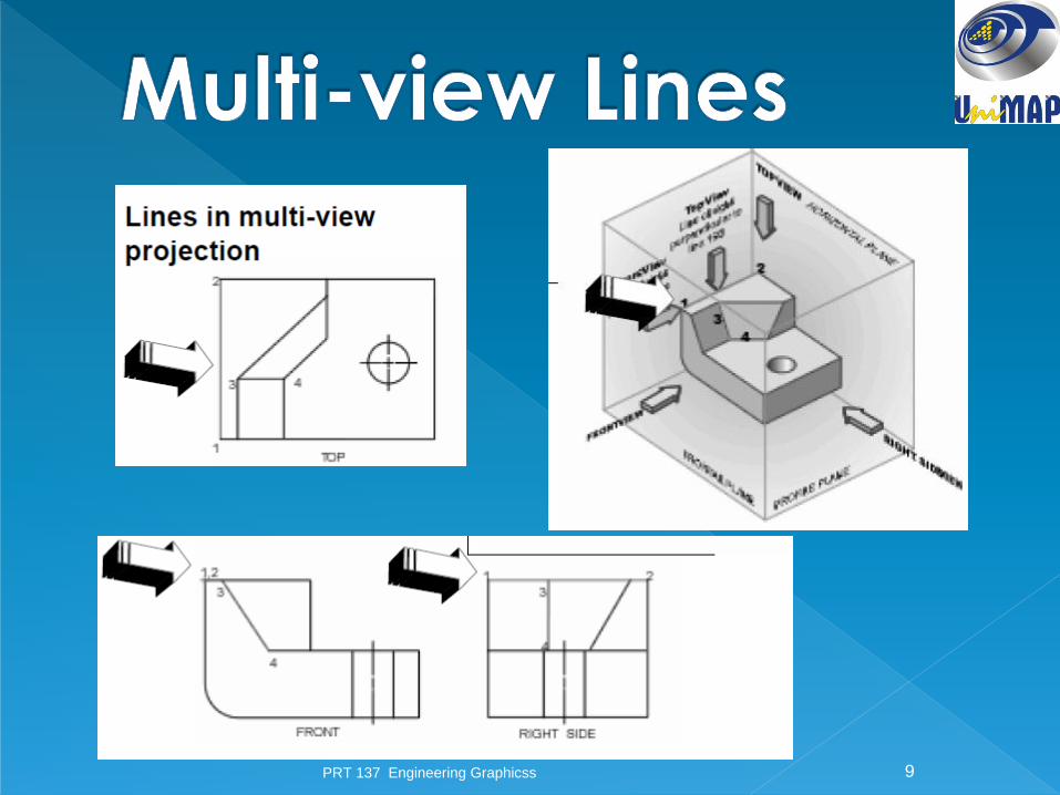
Multi-view Projection
Principle views & View placement
Projection angle
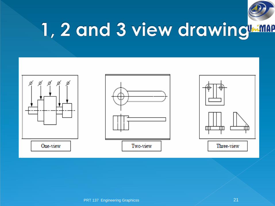
Detail drawing: 1view, 2 view, 3 view
drawing
Creating multi-view drawing
View Selection
2 PRT 137 Engineering Graphicss
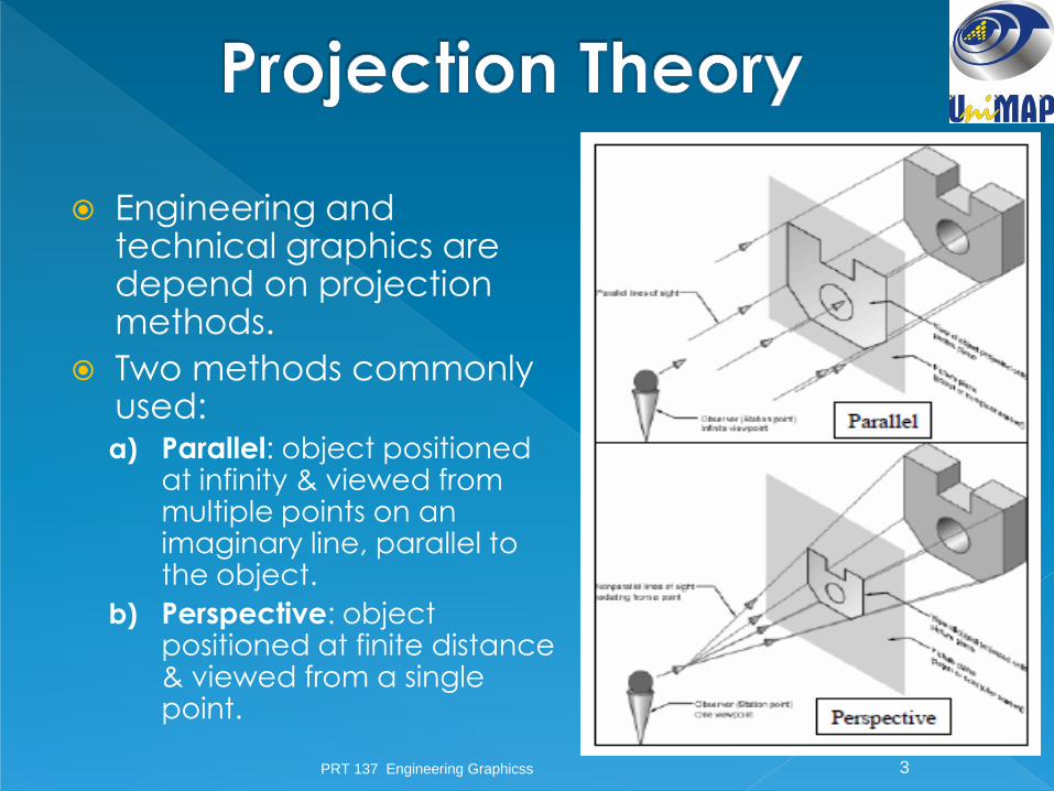
Engineering and technical graphics are depend on projection methods.
Two methods commonly used: a) Parallel: object positioned
at infinity & viewed from multiple points on an imaginary line, parallel to the object.
b) Perspective: object positioned at finite distance & viewed from a single point.
3 PRT 137 Engineering Graphicss
Projection theory comprises of principles used to graphically
represent 3D objects on 2D media based on 2 variables:
i. Line of Sight (LOS): an imaginary ray of light between an
observer’s eye and an object.
• Parallel- all LOS are parallel
• Perspective- all LOS start at a point.
ii. Plane of projection: an imaginary flat plane where the
image created by LOS is projected.
4 PRT 137 Engineering Graphicss

A parallel projection
technique
The projection plane is placed
between observer and object.
The projection plane is also
perpendicular to the parallel
line of sight.
5 PRT 137 Engineering Graphicss
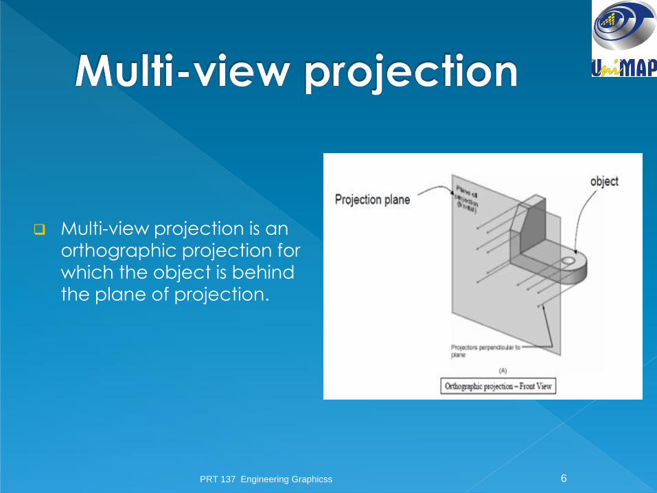
Multi-view projection is an
orthographic projection for
which the object is behind the plane of projection.
6 PRT 137 Engineering Graphicss

Multi-view drawings i. Employ multi-view projection technique
ii. Generally 3 views of an object are drawn
iii. Each view is a 2D flat image
7 PRT 137 Engineering Graphicss

8 PRT 137 Engineering Graphicss
9 PRT 137 Engineering Graphicss

10 PRT 137 Engineering Graphicss
11 PRT 137 Engineering Graphicss

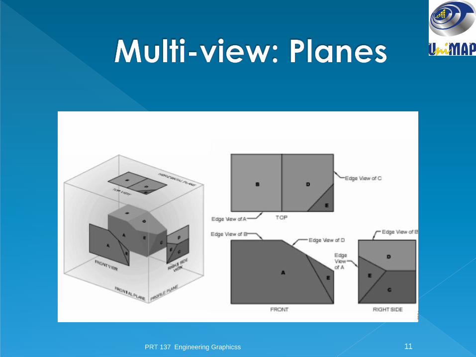
The 6 principle views are the
six mutually perpendicular views that are produced by
six perpendicular planes of projection.
Image an object is
suspended in a glass box,
the 6 sides become
projection plane showing
the six views.
12 PRT 137 Engineering Graphicss
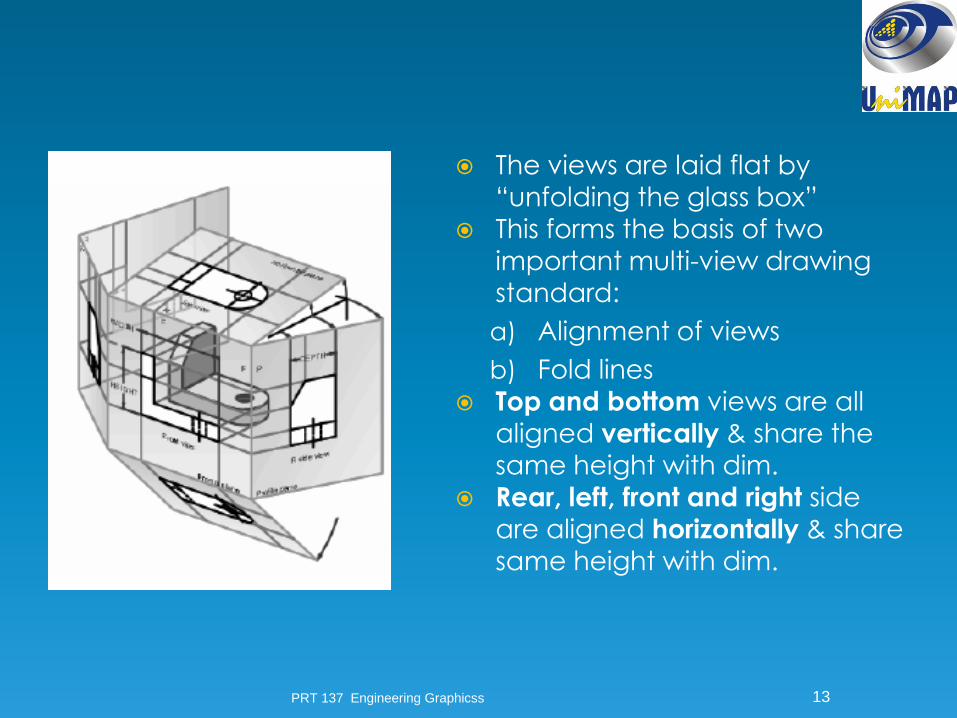
The views are laid flat by
“unfolding the glass box”
This forms the basis of two important multi-view drawing
standard:
a) Alignment of views
b) Fold lines
Top and bottom views are all
aligned vertically & share the
same height with dim.
Rear, left, front and right side
are aligned horizontally & share
same height with dim.
13 PRT 137 Engineering Graphicss

Fold lines are imaginary
hinged edges of the
glass box
i. The fold line between the
top & front views is
labeled H/F
ii. The distance from a point
in front view to the H/F is the same as the distance
from the corresponding
point in the top view to
the H/F fold line.
14 PRT 137 Engineering Graphicss

15 PRT 137 Engineering Graphicss

The arrangement of views may vary as shown,
where the top view is considered the central view.
16 PRT 137 Engineering Graphicss
There are two standard arrangement of
all six views of an object
i. First-angle projection
ii. Third-angle projection
Each uses different symbol
The names are derived from the method
used to view the object being drawn
17 PRT 137 Engineering Graphicss
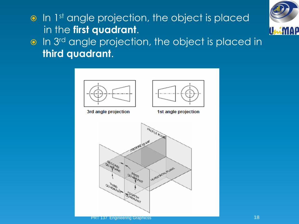
In 1st angle projection, the object is placed
in the first quadrant.
In 3rd angle projection, the object is placed in
third quadrant.
18 PRT 137 Engineering Graphicss

Rules:
Symbols
1st angle
projection
3rd angle
projection
View from
above is placed
underneath
View from
above is placed
above
View from
below is placed
above
View from
below is placed
below
View from left is
placed on right
View from left is
placed on left
View from right
is placed on left
View from right
is placed on
right
(a) 1st angle projection (b) 3rd angle projection
19 PRT 137 Engineering Graphicss

20 PRT 137 Engineering Graphicss
21 PRT 137 Engineering Graphicss

22 PRT 137 Engineering Graphicss
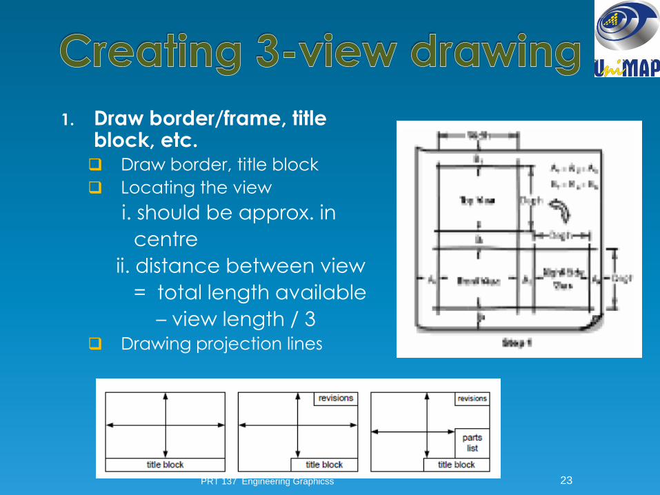
1. Draw border/frame, title block, etc. Draw border, title block
Locating the view
i. should be approx. in
centre
ii. distance between view
= total length available
– view length / 3 Drawing projection lines
23 PRT 137 Engineering Graphicss

2. Light construction of the
views
Draw light/thin horizontal &
vertical lines accordingly for front view
Draw center lines and hidden lines as final
Draw top (or side) view
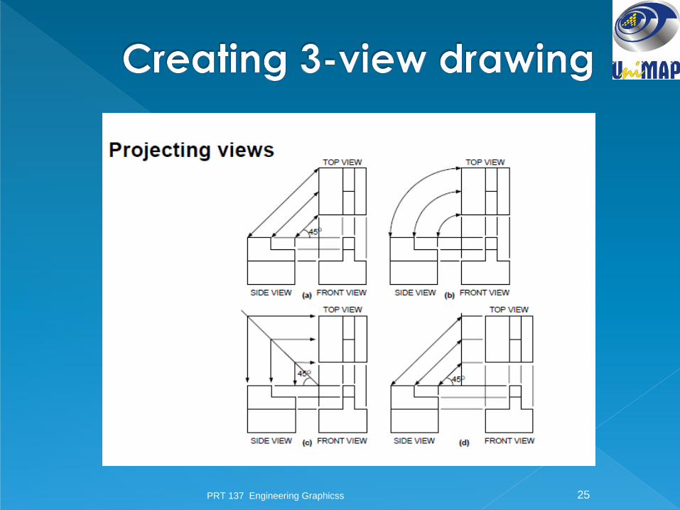
Project top view (or side) from front view using thin, light construction line
Draw side (or top) view
Project side view (or top) from front view and top (or side) view
All arcs and circles should be lined (final) at this stage
24 PRT 137 Engineering Graphicss
25 PRT 137 Engineering Graphicss

3. Lining in of the views
To darken all visible edges (lines that represent a hard edge)
Done using thick, black pencil (0.5mm, 2B)
Should be done systematically for 3 views
Start with horizontal line at the top of the top/plan view, working down the page using T-square
From left hand side, working across the page, line in all vertical lines, using T-square and set square
Projection lines may be left on the drawing if they are light
26 PRT 137 Engineering Graphicss
4. Write dimensioning, notes,
annotation, etc.
Be aware of redundant dimensioning
5. Complete drawing by writing the rest
of title block, parts list & revision table,
and others
27 PRT 137 Engineering Graphicss

4 basic decisions:
1. Determine the best position. The object must be positioned such a way that the surface of major features are either perpendicular or parallel to glass planes
28 PRT 137 Engineering Graphicss
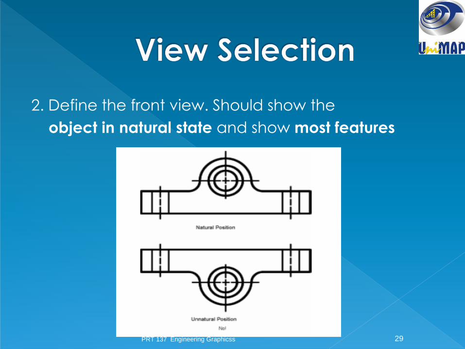
2. Define the front view. Should show the
object in natural state and show most features
29 PRT 137 Engineering Graphicss
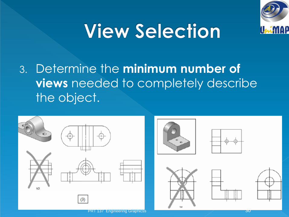
3. Determine the minimum number of
views needed to completely describe
the object.
30 PRT 137 Engineering Graphicss
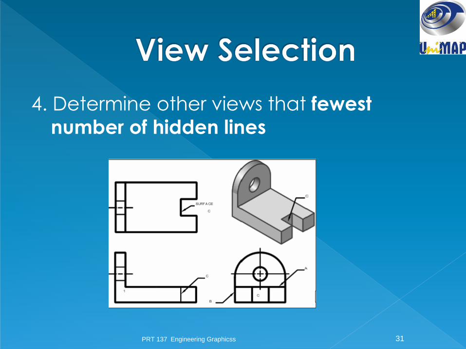
4. Determine other views that fewest
number of hidden lines
PRT 137 Engineering Graphicss 31

THANK YOU…
32 PRT 137 Engineering Graphicss