2 Contents Discrete I/O - Группа компаний … · 2017-02-01 · 2 Contents Discrete...
53
2/1 Schneider Electric 2 2 Contents Discrete I/O Discrete I/O Discrete I/O selection guides . . . . . . . . . . . . . . . . . . . . . . . . . . pages 2/2 to 2/11 b Discrete I/O modules . . . . . . . . . . . . . . . . . . . . . . . . . . . . . . . . pages 2/12 to 2/39 b Telefast 2 pre-wired system: . . . . . . . . . . . . . . . . . . . . . . . . pages 2/40 and 2/41 connector cables FOR Quantum PLCs b Telefast 2 pre-wired system: . . . . . . . . . . . . . . . . . . . . . . . . . . pages 2/42 to 2/47 passive connections and plug-in relay sub-bases b Telefast 2 pre-wired system: . . . . . . . . . . . . . . . . . . . . . . . . . pages 2/48 and 2/49 cables connectors for 984-A120-Compact PLCs b CableFast cabling System. . . . . . . . . . . . . . . . . . . . . . . . . . . . pages 2/50 to 2/53
Transcript of 2 Contents Discrete I/O - Группа компаний … · 2017-02-01 · 2 Contents Discrete...
2 Contents Discrete I/O
2
Discrete I/O
Discrete I/O selection guides . . . . . . . . . . . . . . . . . . . . . . . . . . pages 2/2 to 2/11
b Discrete I/O modules . . . . . . . . . . . . . . . . . . . . . . . . . . . . . . . . pages 2/12 to 2/39
b Telefast 2 pre-wired system: . . . . . . . . . . . . . . . . . . . . . . . . pages 2/40 and 2/41
connector cables FOR Quantum PLCs
b Telefast 2 pre-wired system: . . . . . . . . . . . . . . . . . . . . . . . . . . pages 2/42 to 2/47
passive connections and plug-in relay sub-bases
b Telefast 2 pre-wired system: . . . . . . . . . . . . . . . . . . . . . . . . . pages 2/48 and 2/49
cables connectors for 984-A120-Compact PLCs
b CableFast cabling System. . . . . . . . . . . . . . . . . . . . . . . . . . . . pages 2/50 to 2/53
2/1Schneider Electric
2/2
2
Quantum Automation PlatformDiscrete I/O
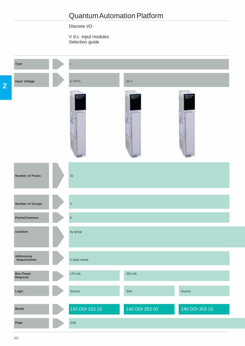
V d.c. input modulesSelection guide
Type a
Input Voltage 5 V/TTL 24 V
Number of Points 32
Number of Groups 4
Points/Common 8
Isolation by group
Addressing Requirements 2 input words
Bus Power 170 mA 330 mARequired
Logic Source Sink Source
Model
Page 2/26
140 DDI 153 10 140 DDI 353 00 140 DDI 353 10
2/3
2
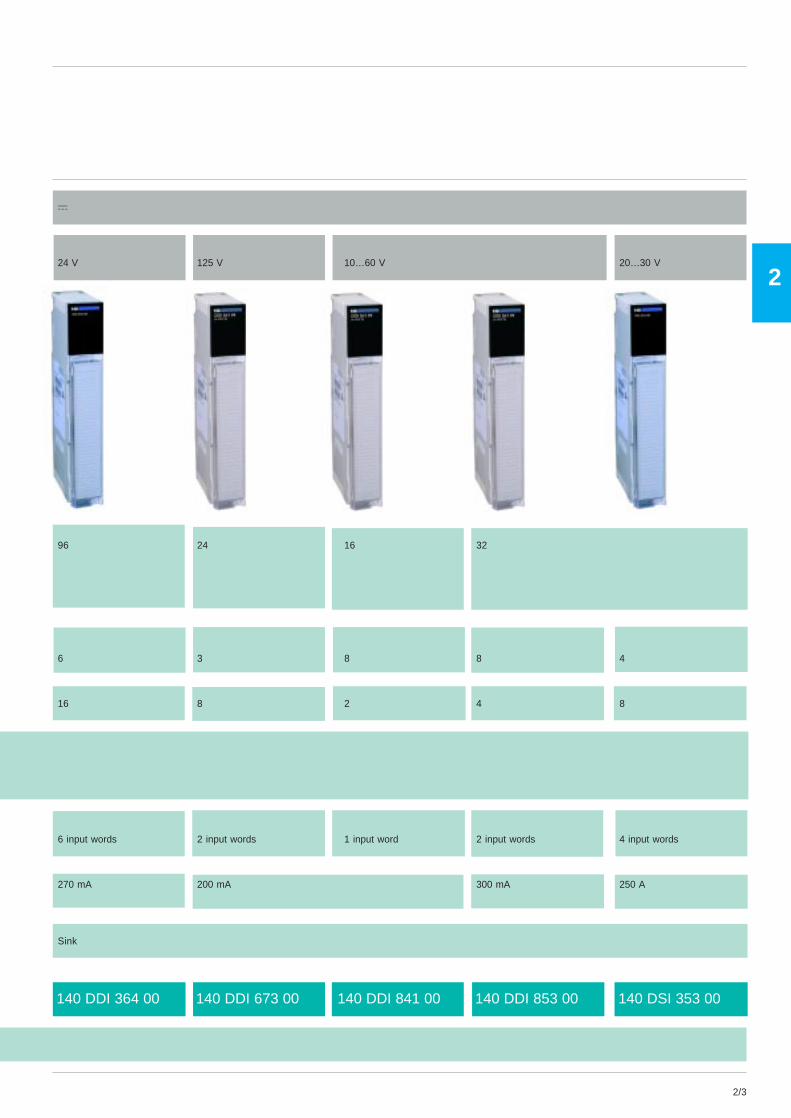
140 DDI 364 00 140 DDI 673 00 140 DDI 841 00 140 DDI 853 00 140 DSI 353 00
a
24 V 125 V 10…60 V 20…30 V
96 24 16 32
6 3 8 8 4
16 8 2 4 8
6 input words 2 input words 1 input word 2 input words 4 input words
270 mA 200 mA 300 mA 250 A
Sink
2/4
2
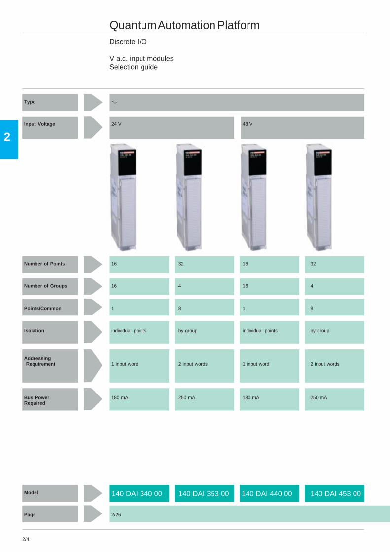
140 DAI 340 00 140 DAI 353 00 140 DAI 440 00 140 DAI 453 00
Quantum Automation PlatformDiscrete I/O
V a.c. input modulesSelection guide
Type c
Input Voltage 24 V 48 V
Number of Points 16 32 16 32
Number of Groups 16 4 16 4
Points/Common 1 8 1 8
Isolation individual points by group individual points by group
Addressing Requirement 1 input word 2 input words 1 input word 2 input words
Bus Power 180 mA 250 mA 180 mA 250 mARequired
Model
Page 2/26
2/5
2
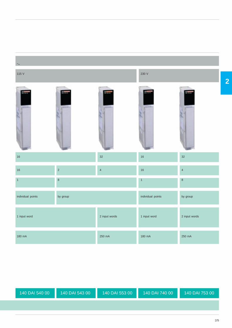
140 DAI 540 00 140 DAI 543 00 140 DAI 553 00 140 DAI 740 00 140 DAI 753 00
c
115 V 230 V
16 32 16 32
16 2 4 16 4
1 8 1 8
individual points by group individual points by group
1 input word 2 input words 1 input word 2 input words
180 mA 250 mA 180 mA 250 mA

2/6
2
140 DDO 353 10140 DDO 153 10 140 DDO 353 0i 140 DDO 364 00
Quantum Automation PlatformDiscrete I/O
V d.c. and relay output modulesSelection guide
Type a
Output voltage/ 5 V/TTL 24 V 19.2…30 VRelay type
Number of points 32 96
Number of groups 4 6
Points/common 8 16
Maximum loadCurrent /point 25 mA .5 ACurrent /group 600 mA 4 A 0.25 ACurrent /module 2.4 A 16 A
Addressingrequirement 2 output words 6 output words
Bus power 350 mA 330 mA 250 mArequired
Logic sink source sink source
Module
Pages 2/26

2/7
2
140 DRA 840 00 140 DRC 830 00140 DDO 843 00 140 DDO 885 00 140 DVO 853 00
a Relay
10 ... 60 V source 24 ... 125 V source 10…30 V Normally open Normally open/Normally closed
16 12 32 16 8
2 6 4 16 8
8 2 8 1
2 A 0.75 A 0.5 A 2 A 5 A6 A 3 A 4 A N/A N/A12 A 6 A 16 A N/A N/A
1 output word 1 input word 2 output words 1 output word 0.5 output word1 output word
160 mA 375 mA @ 6 points on 500 mA 1100 mA 560 mA650 mA @ 12 points on
source
2/26 2/26 2/32

2/8
2
140 DAO 840 00 140 DAO 840 10
Quantum Automation PlatformDiscrete I/O
V a.c. output modulesSelection guide
Type c
Output voltage 24 ... 230 V 24 V ... 115 V
Number of points 16
Number of groups 16
Points/common 1
Maximum loadCurrent /point 4 A @ 20-132 VAC, 8 A @ 170-253 VAC 4 A @ 20-132 VACCurrent /group N/A N/ACurrent /module 16 A 16 A
Addressingrequirement 1 output word
Bus power 350 mArequired
Module
Page 2/26
2/9
2
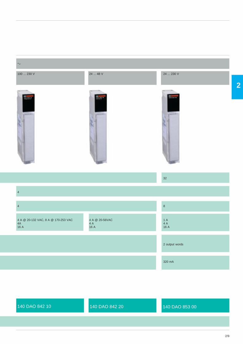
140 DAO 842 10 140 DAO 842 20 140 DAO 853 00
c
100 ... 230 V 24 ... 48 V 24 ... 230 V
32
4
4 8
4 A @ 20-132 VAC, 8 A @ 170-253 VAC 4 A @ 20-56VAC 1 A4A 4 A 4 A16 A 16 A 16 A
2 output words
320 mA
2/10
2
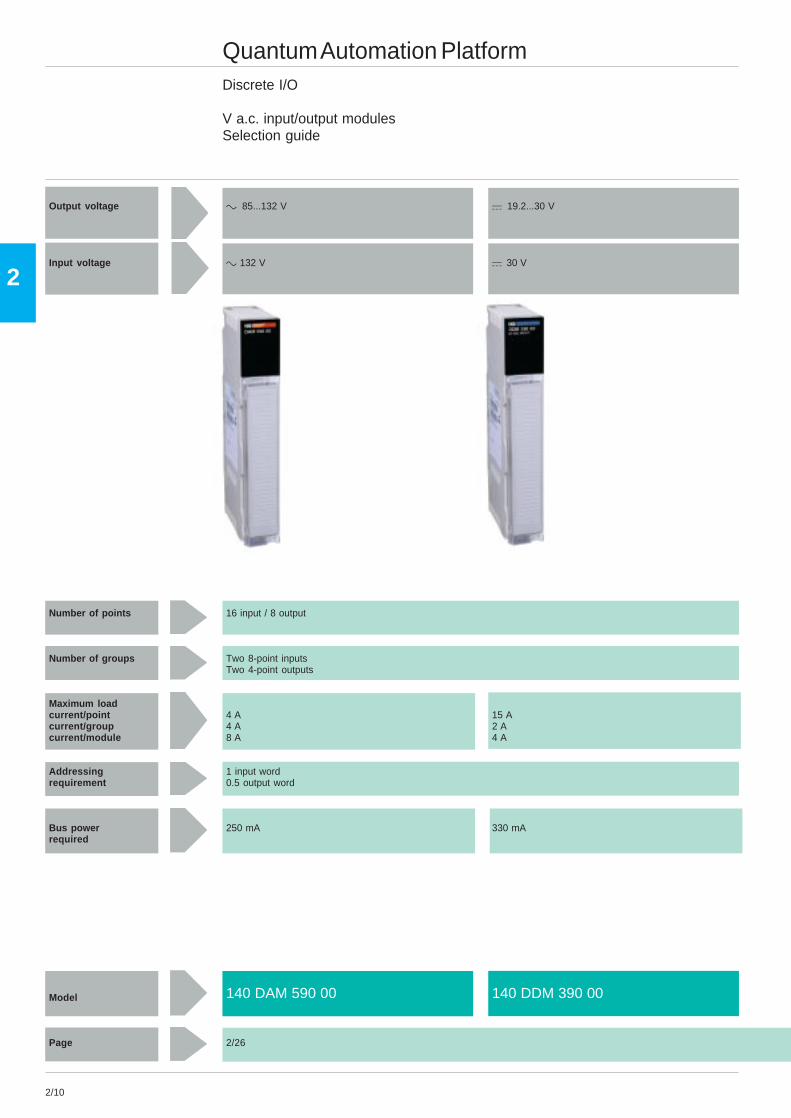
140 DAM 590 00 140 DDM 390 00
Quantum Automation PlatformDiscrete I/O
V a.c. input/output modulesSelection guide
Output voltage c 85...132 V a 19.2...30 V
Input voltage c 132 V a 30 V
Number of points 16 input / 8 output
Number of groups Two 8-point inputsTwo 4-point outputs
Maximum loadcurrent/point 4 A 15 Acurrent/group 4 A 2 Acurrent/module 8 A 4 A
Addressing 1 input wordrequirement 0.5 output word
Bus power 250 mA 330 mArequired
Model
Page 2/26

2/11
2
140 DDM 690 00
a 19.2...156.2 V
a 156.2 V
4 input, 4 isolated output
One 4 point inputsFour output points
4 AN/A16 A
1 input word1 output word
350 mA
2/12
2
1
2
3
4
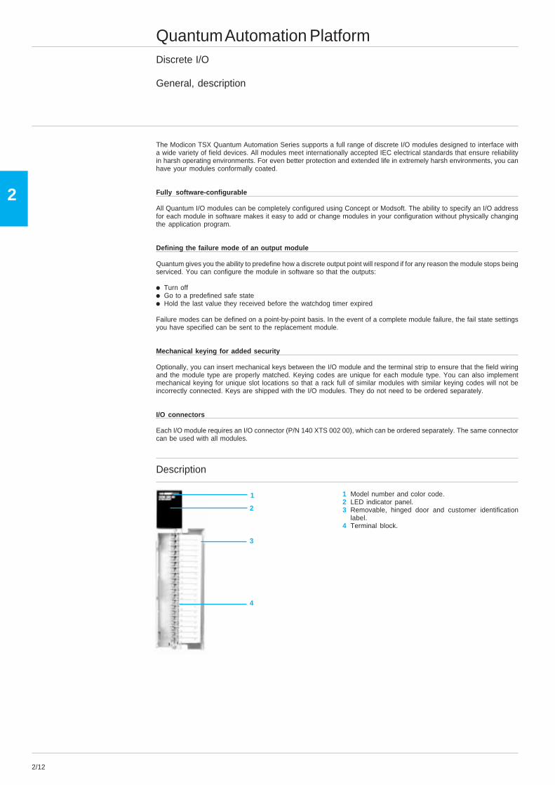
Quantum Automation PlatformDiscrete I/O
General, description
The Modicon TSX Quantum Automation Series supports a full range of discrete I/O modules designed to interface witha wide variety of field devices. All modules meet internationally accepted IEC electrical standards that ensure reliabilityin harsh operating environments. For even better protection and extended life in extremely harsh environments, you canhave your modules conformally coated.
Fully software-configurable
All Quantum I/O modules can be completely configured using Concept or Modsoft. The ability to specify an I/O addressfor each module in software makes it easy to add or change modules in your configuration without physically changingthe application program.
Defining the failure mode of an output module
Quantum gives you the ability to predefine how a discrete output point will respond if for any reason the module stops beingserviced. You can configure the module in software so that the outputs:
i Turn offi Go to a predefined safe statei Hold the last value they received before the watchdog timer expired
Failure modes can be defined on a point-by-point basis. In the event of a complete module failure, the fail state settingsyou have specified can be sent to the replacement module.
Mechanical keying for added security
Optionally, you can insert mechanical keys between the I/O module and the terminal strip to ensure that the field wiringand the module type are properly matched. Keying codes are unique for each module type. You can also implementmechanical keying for unique slot locations so that a rack full of similar modules with similar keying codes will not beincorrectly connected. Keys are shipped with the I/O modules. They do not need to be ordered separately.
I/O connectors
Each I/O module requires an I/O connector (P/N 140 XTS 002 00), which can be ordered separately. The same connectorcan be used with all modules.
Description
1 Model number and color code.2 LED indicator panel.3 Removable, hinged door and customer identification
label.4 Terminal block.
2/13
2
1
2
3
4
5
6
7
8
Active
9
10
11
12
13
14
15
16
17
18
19
20
21
22
23
24
F
25
26
27
28
29
30
31
32
1
2
Active
1
2
F
1
2
3
4
Quantum Automation PlatformDiscrete I/O
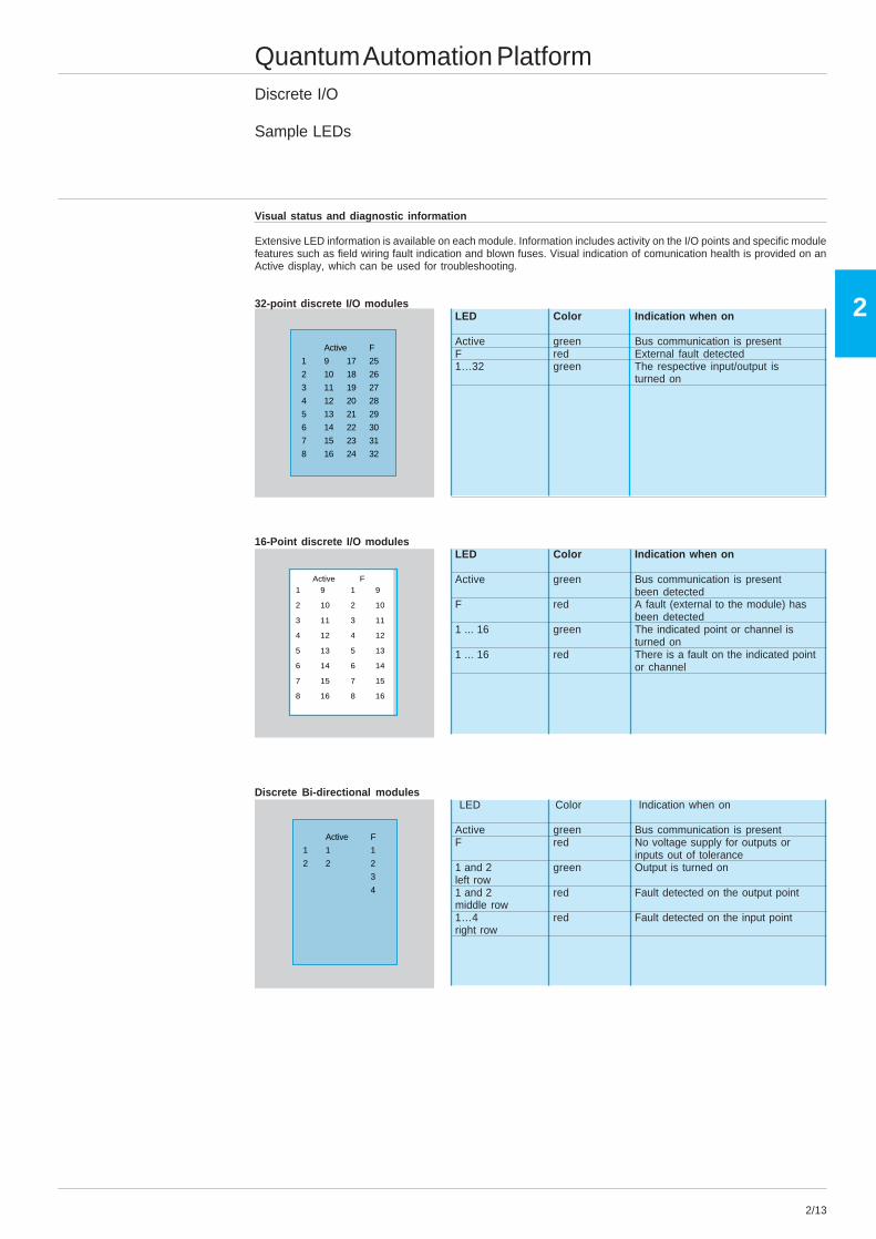
Sample LEDs
Visual status and diagnostic information
Extensive LED information is available on each module. Information includes activity on the I/O points and specific modulefeatures such as field wiring fault indication and blown fuses. Visual indication of comunication health is provided on anActive display, which can be used for troubleshooting.
32-point discrete I/O modulesLED Color Indication when on
Active green Bus communication is presentF red External fault detected1…32 green The respective input/output is
turned on
16-Point discrete I/O modulesLED Color Indication when on
Active green Bus communication is presentbeen detected
F red A fault (external to the module) hasbeen detected
1 ... 16 green The indicated point or channel isturned on
1 ... 16 red There is a fault on the indicated pointor channel
Discrete Bi-directional modulesLED Color Indication when on
Active green Bus communication is presentF red No voltage supply for outputs or
inputs out of tolerance1 and 2 green Output is turned onleft row1 and 2 red Fault detected on the output pointmiddle row1…4 red Fault detected on the input pointright row
Active F
1 9 1 9
2 10 2 10
3 11 3 11
4 12 4 12
5 13 5 13
6 14 6 14
7 15 7 15
8 16 8 16
2/14
2
Quantum Automation PlatformDiscrete I/O
Characteristics
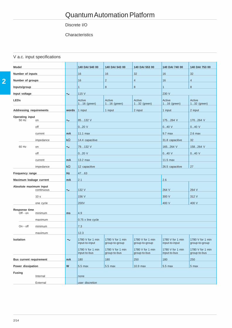
V a.c. input specifications
Model 140 DAI 540 00 140 DAI 543 00 140 DAI 553 00 140 DAI 740 00 140 DAI 753 00
Number of inputs 16 16 32 16 32
Number of groups 16 2 4 16 4
Inputs/group 1 8 8 1 8
Input voltage ccccc 115 V 230 V
LEDs Active Active Active Active Active1…16 (green) 1…16 (green) 1…32 (green) 1…16 (green) 1...32 (green)
Addressing requirements words 1 input 1 input 2 input 1 input 2 input
Operating input50 Hz on ccccc 85…132 V 175…264 V 170...264 V
off 0...20 V 0...40 V 0...40 V
current mA 11.1 max 9.7 max 2.6 max
impedance kΩ 14.4 capacitive 31.8 capacitive 32
60 Hz on ccccc 79…132 V 165...264 V 158...264 V
off 0...20 V 0...40 V 0...40 V
current mA 13.2 max 11.5 max
impedance kΩ 12 capacitive 26.5 capacitive 27
Frequency range Hz 47…63
Maximum leakage current mA 2.1 2.6
Absolute maximum inputcontinuous ccccc 132 V 264 V 264 V
10 s 156 V 300 V 312 V
one cycle 200V 400 V 400 V
Response timeOff - on minimum ms 4.9
maximum 0.75 x line cycle
On - off minimum 7.3
maximum 12.3
Isolation ccccc 1780 V for 1 min 1780 V for 1 min 1780 V for 1 min 1780 V for 1 min 1780 V for 1 mininput-to-input group-to-group group-to-group input-to-input group-to-group
1780 V for 1 min 1780 V for 1 min 1780 V for 1 min 1780 V for 1 min 1780 V for 1 mininput-to-bus group-to-bus group-to-bus input-to-bus group-to-bus
Bus current requirement mA 180 180 250 180 250
Power dissipation W 5.5 max 5.5 max 10.9 max 5.5 max 5 max
FusingInternal none
External user discretion
2/15
2
Quantum Automation PlatformDiscrete I/O
Characteristics (continued)
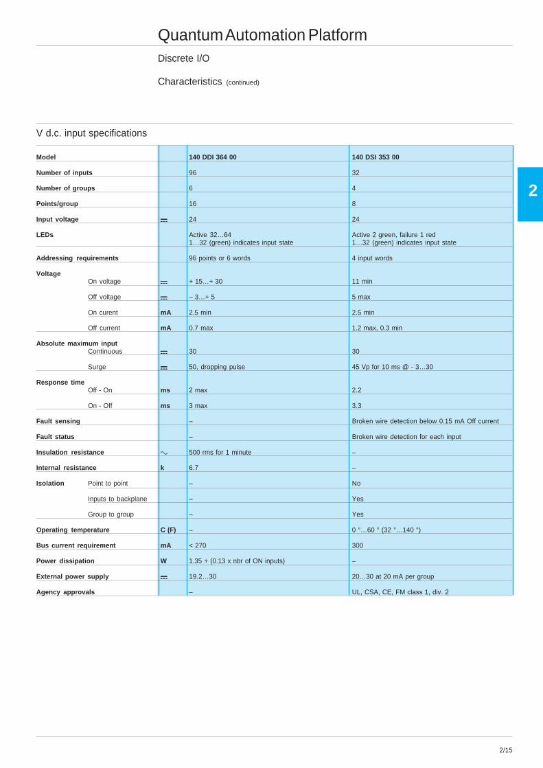
V d.c. input specifications
Model 140 DDI 364 00 140 DSI 353 00
Number of inputs 96 32
Number of groups 6 4
Points/group 16 8
Input voltage aaaaa 24 24
LEDs Active 32…64 Active 2 green, failure 1 red1…32 (green) indicates input state 1…32 (green) indicates input state
Addressing requirements 96 points or 6 words 4 input words
VoltageOn voltage aaaaa + 15…+ 30 11 min
Off voltage aaaaa – 3…+ 5 5 max
On curent mA 2.5 min 2.5 min
Off current mA 0.7 max 1.2 max, 0.3 min
Absolute maximum inputContinuous aaaaa 30 30
Surge aaaaa 50, dropping pulse 45 Vp for 10 ms @ - 3…30
Response timeOff - On ms 2 max 2.2
On - Off ms 3 max 3.3
Fault sensing – Broken wire detection below 0.15 mA Off current
Fault status – Broken wire detection for each input
Insulation resistance c 500 rms for 1 minute –
Internal resistance k 6.7 –
Isolation Point to point – No
Inputs to backplane – Yes
Group to group – Yes
Operating temperature C (F) – 0 °…60 ° (32 °…140 °)
Bus current requirement mA < 270 300
Power dissipation W 1.35 + (0.13 x nbr of ON inputs) –
External power supply aaaaa 19.2…30 20…30 at 20 mA per group
Agency approvals – UL, CSA, CE, FM class 1, div. 2
2/16
2
Quantum Automation PlatformDiscrete I/O
Characteristics (continued)
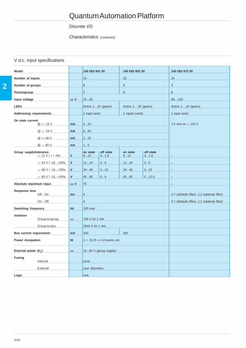
V d.c. input specifications
Model 140 DDI 841 00 140 DDI 853 00 140 DDI 673 00
Number of inputs 16 32 24
Number of groups 8 4 3
Points/group 2 8 8
Input voltage aaaaa V 10...60 88…150
LEDs Active 1…16 (green) Active 1….32 (green) Active 1….24 (green)
Addressing requirements 1 input word 2 inputs words 1 input word
On state current@ a 12 V mA 5...10 2.5 mini at a 125 V
@ a 24 V mA 6...30
@ a 48 V mA 2...15
@ a 60 V mA 1...5
Group supply/tolerance on state off state on state off statea 12 V / + / -5% V 9...12 0...1.8 9...12 0...1.8 –
a 24 V / -15...+20% V 11...24 0...5 11...24 0...5 –
a 48 V / -15...+20% V 34...48 0...10 34...48 0...10 –
a 60 V / -15...+20% V 45...60 0...9 45...60 0...12.5 –
Absolute maximum input aaaaa V 75 –
Response timeOff - On ms 4 0,7 (defaults filter), 1,2 (optional filter)
On - Off 4 0,7 (defaults filter), 1,2 (optional filter)
Switching frequency Hz 100 max
IsolationGroup-to-group aaaaa 700 V for 1 min
Group-to-bus 2500 V for 1 min
Bus current requirement mA 200 300
Power dissipation W 1 + (0.25 x # of points on)
External power (U S) aaaaa 10...60 V (group supply)
FusingInternal none
External user discretion
Logic sink
2/17
2
Quantum Automation PlatformDiscrete I/O
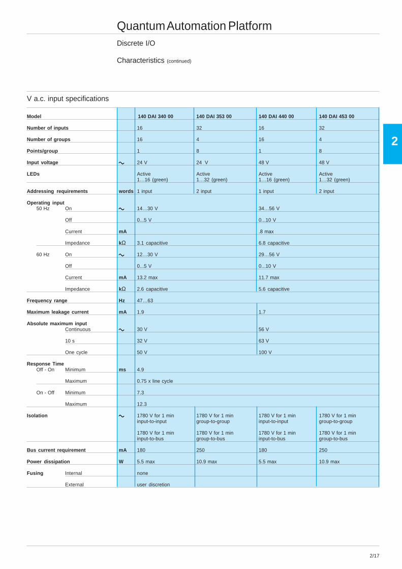
Characteristics (continued)
V a.c. input specifications
Model 140 DAI 340 00 140 DAI 353 00 140 DAI 440 00 140 DAI 453 00
Number of inputs 16 32 16 32
Number of groups 16 4 16 4
Points/group 1 8 1 8
Input voltage ccccc 24 V 24 V 48 V 48 V
LEDs Active Active Active Active1…16 (green) 1…32 (green) 1…16 (green) 1…32 (green)
Addressing requirements words 1 input 2 input 1 input 2 input
Operating input50 Hz On ccccc 14…30 V 34…56 V
Off 0...5 V 0...10 V
Current mA .8 max
Impedance kΩ 3.1 capacitive 6.8 capacitive
60 Hz On ccccc 12…30 V 29…56 V
Off 0...5 V 0...10 V
Current mA 13.2 max 11.7 max
Impedance kΩ 2.6 capacitive 5.6 capacitive
Frequency range Hz 47…63
Maximum leakage current mA 1.9 1.7
Absolute maximum inputContinuous ccccc 30 V 56 V
10 s 32 V 63 V
One cycle 50 V 100 V
Response TimeOff - On Minimum ms 4.9
Maximum 0.75 x line cycle
On - Off Minimum 7.3
Maximum 12.3
Isolation ccccc 1780 V for 1 min 1780 V for 1 min 1780 V for 1 min 1780 V for 1 mininput-to-input group-to-group input-to-input group-to-group
1780 V for 1 min 1780 V for 1 min 1780 V for 1 min 1780 V for 1 mininput-to-bus group-to-bus input-to-bus group-to-bus
Bus current requirement mA 180 250 180 250
Power dissipation W 5.5 max 10.9 max 5.5 max 10.9 max
Fusing Internal none
External user discretion

2/18
2
Quantum Automation PlatformDiscrete I/O
Characteristics (continued)
V d.c. input specifications
Model 140 DDI 153 10 140 DDI 353 00/140 DDI 353 01 140 DDI 353 10
Number of inputs 32
Number of groups 4
Points/group 8
Input voltage aaaaa 5 V TTL 24 V
LEDs Active 1…32 (green)
Addressing requirements 2 input words
Operating inputVoltage on aaaaa 0.8 V + 15...30 V - 15...30 V (reference from
group supply)
Voltage off 4 V min @ US= 5.5 V - 3...+ 5 V 0...- 5 V (reference from3 V min @ US= 4.5 V group supply)
Current on mA 4.0 @ US= 5.5 V and UIN=0 2.0 min 2.5 min14 max
Current off – 0.5 max 0.5 max
Internal resistance k ΩΩΩΩΩ 7.5 2.5 2.4
Leakage current µµµµµA 200 @ US= 5.5 V and UIN=4 V –
Absolute maximum inputContinuous aaaaa 5.5 V 30 V 30 V
1.0 ms – – 50 V decaying pulse
1.3 ms 15 V decaying pulse 56 V decaying pulse –
Response timeOff - on µµµµµs 250 max 1000 max
On - off 500 max 1000 max
Input protection Resistor limited
IsolationGroup-to-group ccccc 500 V rms for 1 min
Group-to-bus 1780 V rms for 1 min
Bus current requirement mA 170 330
Power dissipation W 5 1.7 + (0.36 x # of points on) 1.5 + (0.26 x # of points on)
External power (U S) aaaaa 4.5...5.5 V none 19.2...30 V
FusingInternal none
External user discretion
Logic source sink source
2/19
2
Quantum Automation PlatformDiscrete I/O
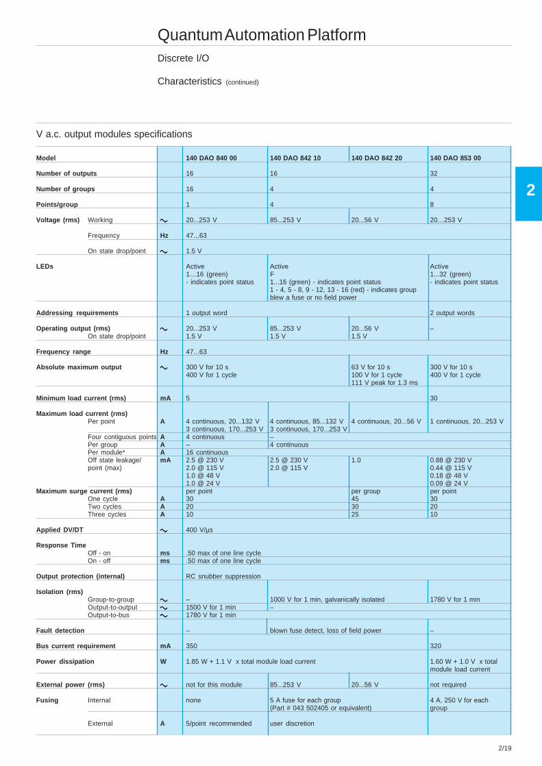
Characteristics (continued)
V a.c. output modules specifications
Model 140 DAO 840 00 140 DAO 842 10 140 DAO 842 20 140 DAO 853 00
Number of outputs 16 16 32
Number of groups 16 4 4
Points/group 1 4 8
Voltage (rms) Working ccccc 20...253 V 85...253 V 20...56 V 20…253 V
Frequency Hz 47...63
On state drop/point ccccc 1.5 V
LEDs Active Active Active1…16 (green) F 1...32 (green)- indicates point status 1...16 (green) - indicates point status - indicates point status
1 - 4, 5 - 8, 9 - 12, 13 - 16 (red) - indicates groupblew a fuse or no field power
Addressing requirements 1 output word 2 output words
Operating output (rms) ccccc 20...253 V 85...253 V 20...56 V –On state drop/point 1.5 V 1.5 V 1.5 V
Frequency range Hz 47...63
Absolute maximum output ccccc 300 V for 10 s 63 V for 10 s 300 V for 10 s400 V for 1 cycle 100 V for 1 cycle 400 V for 1 cycle
111 V peak for 1.3 ms
Minimum load current (rms) mA 5 30
Maximum load current (rms)Per point A 4 continuous, 20...132 V 4 continuous, 85...132 V 4 continuous, 20...56 V 1 continuous, 20...253 V
3 continuous, 170...253 V 3 continuous, 170...253 VFour contiguous points A 4 continuous –Per group A – 4 continuousPer module* A 16 continuousOff state leakage/ mA 2.5 @ 230 V 2.5 @ 230 V 1.0 0.88 @ 230 Vpoint (max) 2.0 @ 115 V 2.0 @ 115 V 0.44 @ 115 V
1.0 @ 48 V 0.18 @ 48 V1.0 @ 24 V 0.09 @ 24 V
Maximum surge current (rms) per point per group per pointOne cycle A 30 45 30Two cycles A 20 30 20Three cycles A 10 25 10
Applied DV/DT ccccc 400 V/µs
Response TimeOff - on ms .50 max of one line cycleOn - off ms .50 max of one line cycle
Output protection (internal) RC snubber suppression
Isolation (rms)Group-to-group ccccc – 1000 V for 1 min, galvanically isolated 1780 V for 1 minOutput-to-output ccccc 1500 V for 1 min –Output-to-bus ccccc 1780 V for 1 min
Fault detection – blown fuse detect, loss of field power –
Bus current requirement mA 350 320
Power dissipation W 1.85 W + 1.1 V x total module load current 1.60 W + 1.0 V x totalmodule load current
External power (rms) ccccc not for this module 85...253 V 20...56 V not required
Fusing Internal none 5 A fuse for each group 4 A, 250 V for each(Part # 043 502405 or equivalent) group
External A 5/point recommended user discretion
2/20
2
Quantum Automation PlatformDiscrete I/O
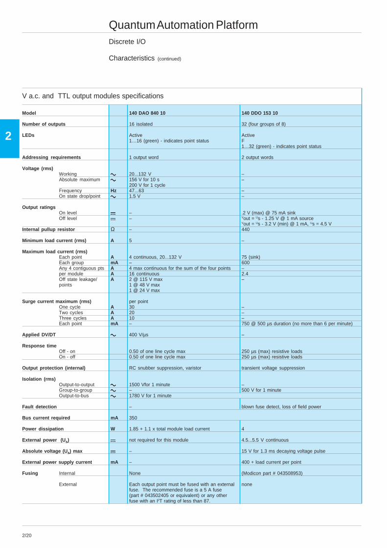
Characteristics (continued)
V a.c. and TTL output modules specifications
Model 140 DAO 840 10 140 DDO 153 10
Number of outputs 16 isolated 32 (four groups of 8)
LEDs Active Active1…16 (green) - indicates point status F
1…32 (green) - indicates point status
Addressing requirements 1 output word 2 output words
Voltage (rms)Working ccccc 20...132 V –Absolute maximum ccccc 156 V for 10 s –
200 V for 1 cycleFrequency Hz 47...63 –On state drop/point ccccc 1.5 V –
Output ratingsOn level aaaaa – .2 V (max) @ 75 mA sinkOff level aaaaa – Vout = Us - 1.25 V @ 1 mA source
Vout = Us - 3.2 V (min) @ 1 mA, Us = 4.5 VInternal pullup resistor Ω – 440
Minimum load current (rms) A 5 –
Maximum load current (rms)Each point A 4 continuous, 20...132 V 75 (sink)Each group mA – 600Any 4 contiguous pts A 4 max continuous for the sum of the four points –per module A 16 continuous 2.4Off state leakage/ A 2 @ 115 V max –points 1 @ 48 V max
1 @ 24 V max
Surge current maximum (rms) per pointOne cycle A 30 –Two cycles A 20 –Three cycles A 10 –Each point mA – 750 @ 500 µs duration (no more than 6 per minute)
Applied DV/DT ccccc 400 V/µs –
Response timeOff - on 0.50 of one line cycle max 250 µs (max) resistive loadsOn - off 0.50 of one line cycle max 250 µs (max) resistive loads
Output protection (internal) RC snubber suppression, varistor transient voltage suppression
Isolation (rms)Output-to-output ccccc 1500 Vfor 1 minute –Group-to-group ccccc – 500 V for 1 minuteOutput-to-bus ccccc 1780 V for 1 minute
Fault detection – blown fuse detect, loss of field power
Bus current required mA 350
Power dissipation W 1.85 + 1.1 x total module load current 4
External power (Us) aaaaa not required for this module 4.5...5.5 V continuous
Absolute voltage (U s) max aaaaa – 15 V for 1.3 ms decaying voltage pulse
External power supply current mA – 400 + load current per point
Fusing Internal None (Modicon part # 043508953)
External Each output point must be fused with an external nonefuse. The recommended fuse is a 5 A fuse(part # 043502405 or equivalent) or any otherfuse with an I2T rating of less than 87.
2/21
2
Quantum Automation PlatformDiscrete I/O
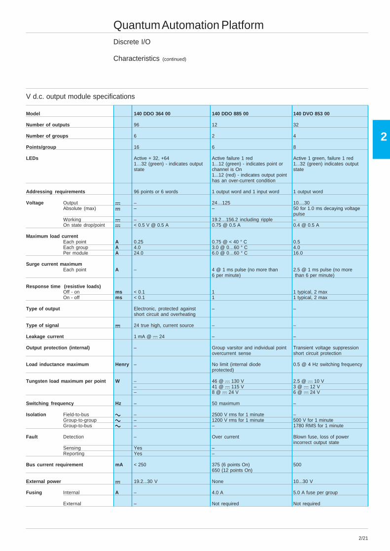
Characteristics (continued)
V d.c. output module specifications
Model 140 DDO 364 00 140 DDO 885 00 140 DVO 853 00
Number of outputs 96 12 32
Number of groups 6 2 4
Points/group 16 6 8
LEDs Active + 32, +64 Active failure 1 red Active 1 green, failure 1 red1…32 (green) - indicates output 1...12 (green) - indicates point or 1...32 (green) indicates outputstate channel is On state
1...12 (red) - indicates output pointhas an over-current condition
Addressing requirements 96 points or 6 words 1 output word and 1 input word 1 output word
Voltage Output aaaaa – 24…125 10....30Absolute (max) aaaaa – – 50 for 1.0 ms decaying voltage
pulseWorking aaaaa – 19.2…156.2 including ripple –On state drop/point aaaaa < 0.5 V @ 0.5 A 0.75 @ 0.5 A 0.4 @ 0.5 A
Maximum load currentEach point A 0.25 0.75 @ < 40 ° C 0.5Each group A 4.0 3.0 @ 0…60 ° C 4.0Per module A 24.0 6.0 @ 0…60 ° C 16.0
Surge current maximumEach point A – 4 @ 1 ms pulse (no more than 2.5 @ 1 ms pulse (no more
6 per minute) than 6 per minute)
Response time (resistive loads)Off - on ms < 0.1 1 1 typical, 2 maxOn - off ms < 0.1 1 1 typical, 2 max
Type of output Electronic, protected against – –short circuit and overheating
Type of signal aaaaa 24 true high, current source – –
Leakage current 1 mA @ a 24 – –
Output protection (internal) – Group varsitor and individual point Transient voltage suppressionovercurrent sense short circuit protection
Load inductance maximum Henry – No limit (internal diode 0.5 @ 4 Hz switching frequencyprotected)
Tungsten load maximum per point W – 46 @ a 130 V 2.5 @ a 10 V– 41 @ a 115 V 3 @ a 12 V– 8 @ a 24 V 6 @ a 24 V
Switching frequency Hz – 50 maximum –
Isolation Field-to-bus ccccc – 2500 V rms for 1 minute –Group-to-group ccccc – 1200 V rms for 1 minute 500 V for 1 minuteGroup-to-bus ccccc – – 1780 RMS for 1 minute
Fault Detection – Over current Blown fuse, loss of powerincorrect output state
Sensing Yes –Reporting Yes –
Bus current requirement mA < 250 375 (6 points On) 500650 (12 points On)
External power aaaaa 19.2...30 V None 10...30 V
Fusing Internal A – 4.0 A 5.0 A fuse per group
External – Not required Not required

2/22
2
Quantum Automation PlatformDiscrete I/O
Characteristics (continued)
V d.c. output module specifications
Model 140 DDO 353 00 140 DDO 353 10/140 DDO 353 01 140 DDO 843 00
Number of outputs 32 (4 groups of 8) 16 (2 groups of 8)
LEDs Active ActiveF 1...16 (green) - indicates point1…32 (green) indicates point status status
Addressing requirements 2 output words 1 output word
VoltageOperating (max) aaaaa 19.2...30 V 10.2...72 VAbsolute (max) aaaaa 56 V for 1.3 ms decaying voltage –
pulse 72 V continuous)1.0 ms aaaaa – 50 V decaying pulse –On state drop/point aaaaa 0.4 V @ 0.5 A 1 V max @ 2 A
Maximum load currentEach point A 0.5 2Each group A 4 6Per module A 16 12Off state leakage/point mA 0.4 @ 30 V 1 @ 60 V max
Surge current maximumEach point A 5 @ 500 µs duration (no more 5 @ 1 ms duration (no more 7.5 @ 50 ms duration (no more
than 6 per minute) than 6 per minute) than 20 per minute)
Response time (resistive loads)Off - on ms 1 (max)On - off ms 1 (max)
Output protection (internal) transient voltage suppression transient voltage overload and over voltage (suppression diode)suppression short-circuit-proof
through tempe-rature supervision
Load inductance maximum Hz 0.5 Henry @ 4 switch frequency –orL = 0.5 where: L = Load Inductance (Henry) I2 F I = Load Current (A)
F = Switching Frequency (Hz)
Load capacitance maximum µF 50 – –
Tungsten load maximum W – 12 @ 24 V –
IsolationGroup-to-group aaaaa 500 V rms for 1 minute 700 V for 1 minuteOutput-to-bus aaaaa 1780 V rms for 1 minute –Group-to-bus aaaaa – – 2500 V for 1 minute
Fault detection blown fuse detect, loss of field power –
Bus current requirement mA 330 330 (max) 160
Power dissipation W 1.75 + 0.4 V x total module 2.0 + (0.4 V x total load current) 1 + 1 V x total module load load current current
External power aaaaa 19.2...30 V 10...60 V
FusingInternal A 5.0/group 8/group time-lagExternal 5/group 8/group
The group fuse is not guaranteed to protect Thegroup fuse is not guaranteed each output switch for all possible overload conditions. to protect each output switch
for all possible overload3/point recommended, (part #57-0078-000) conditions.
2/point recommended(Modicon fuse#: 57-0060-00)
Logic source sink source
2/23
2
Quantum Automation PlatformDiscrete I/O
Characteristics (continued)
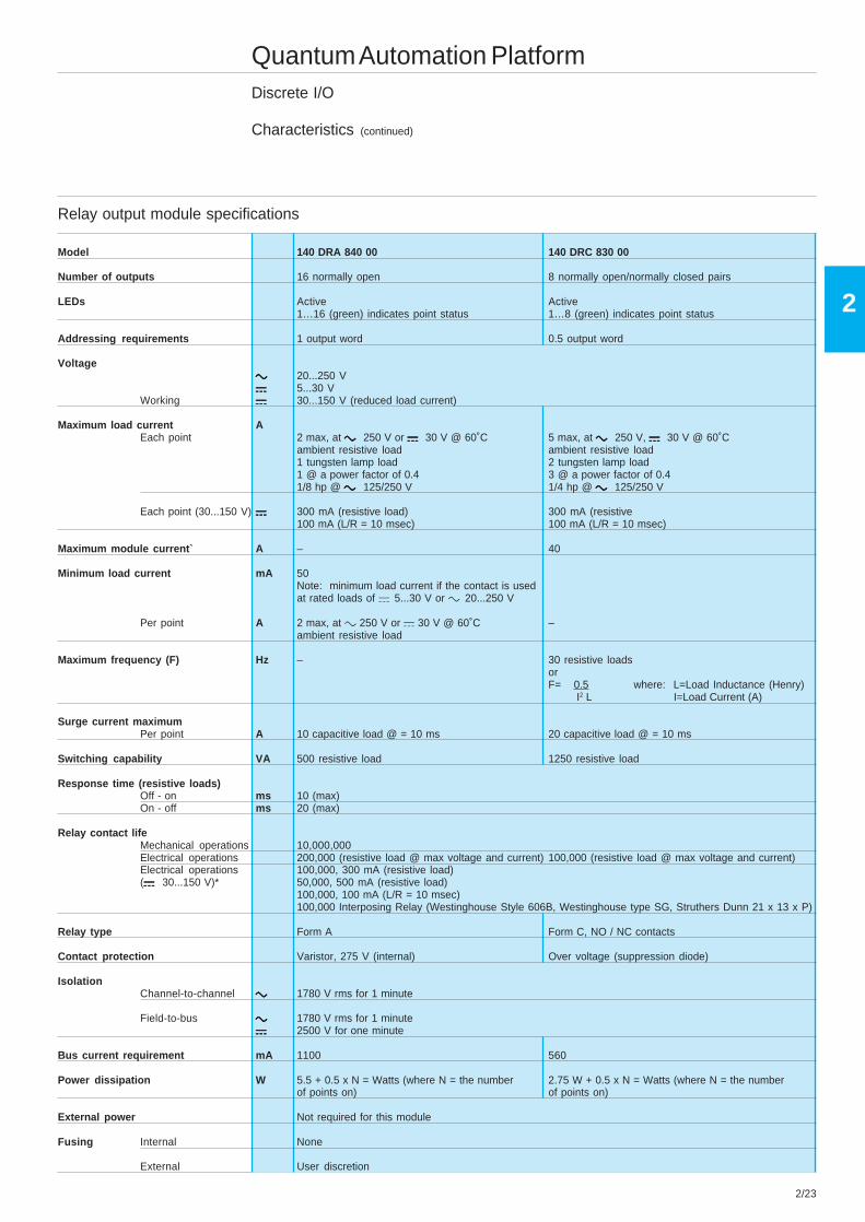
Relay output module specifications
Model 140 DRA 840 00 140 DRC 830 00
Number of outputs 16 normally open 8 normally open/normally closed pairs
LEDs Active Active1…16 (green) indicates point status 1…8 (green) indicates point status
Addressing requirements 1 output word 0.5 output word
Voltageccccc 20...250 Vaaaaa 5...30 V
Working aaaaa 30...150 V (reduced load current)
Maximum load current AEach point 2 max, at c c c c c 250 V or a a a a a 30 V @ 60˚C 5 max, at c c c c c 250 V, a a a a a 30 V @ 60˚C
ambient resistive load ambient resistive load1 tungsten lamp load 2 tungsten lamp load1 @ a power factor of 0.4 3 @ a power factor of 0.41/8 hp @ c c c c c 125/250 V 1/4 hp @ c c c c c 125/250 V
Each point (30...150 V) aaaaa 300 mA (resistive load) 300 mA (resistive100 mA (L/R = 10 msec) 100 mA (L/R = 10 msec)
Maximum module current` A – 40
Minimum load current mA 50Note: minimum load current if the contact is usedat rated loads of a 5...30 V or c 20...250 V
Per point A 2 max, at c 250 V or a 30 V @ 60˚C –ambient resistive load
Maximum frequency (F) Hz – 30 resistive loadsorF= 0.5 where: L=Load Inductance (Henry) I2 L I=Load Current (A)
Surge current maximumPer point A 10 capacitive load @ = 10 ms 20 capacitive load @ = 10 ms
Switching capability VA 500 resistive load 1250 resistive load
Response time (resistive loads)Off - on ms 10 (max)On - off ms 20 (max)
Relay contact lifeMechanical operations 10,000,000Electrical operations 200,000 (resistive load @ max voltage and current) 100,000 (resistive load @ max voltage and current)Electrical operations 100,000, 300 mA (resistive load)(a a a a a 30...150 V)* 50,000, 500 mA (resistive load)
100,000, 100 mA (L/R = 10 msec)100,000 Interposing Relay (Westinghouse Style 606B, Westinghouse type SG, Struthers Dunn 21 x 13 x P)
Relay type Form A Form C, NO / NC contacts
Contact protection Varistor, 275 V (internal) Over voltage (suppression diode)
IsolationChannel-to-channel ccccc 1780 V rms for 1 minute
Field-to-bus ccccc 1780 V rms for 1 minuteaaaaa 2500 V for one minute
Bus current requirement mA 1100 560
Power dissipation W 5.5 + 0.5 x N = Watts (where N = the number 2.75 W + 0.5 x N = Watts (where N = the numberof points on) of points on)
External power Not required for this module
Fusing Internal None
External User discretion

2/24
2
Quantum Automation PlatformDiscrete I/O
Characteristics (continued)
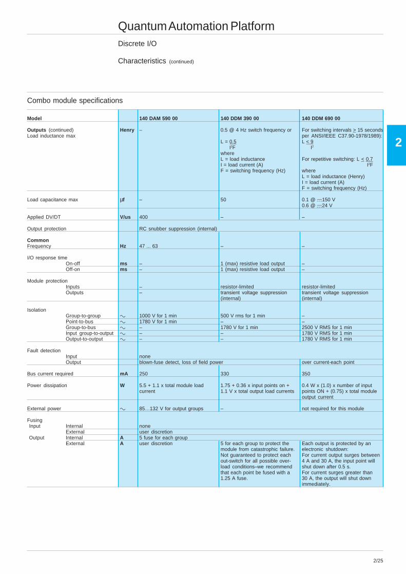
Combo module specifications
Model 140 DAM 590 00 140 DDM 390 00 140 DDM 690 00
Number of inputs 16 (2 groups of 8) 4 (1 group of 4)
Number of outputs 8 (2 groups of 4) 4 isolated
LEDs ActiveF (red) - no power applied to the group(s) or blown fuse1…16 (green - right two columns) - indicates input status1...8 (green - left column) - indicates output status
Addressing requirements 1 in/0.5 out word
InputsOperating voltage
On zzzzz c 85...132 V @ 50 Hz a + 15...+ 30 V a 88 ... 156.2 V, including ripplec 79...132 V @ 60 Hz
Off zzzzz c 0...20 V a - 3...+ 5 V a 0 ... + 36 VImpedance kΩ 14.4 capacitive 2.5 –
CurrentOn mA 11.1 max @ 50 Hz 2.0 min. 2.0 min.
13.2 max @ 60 HzOff mA 0.5 max. 0.5 max 1.2 max.
Leakage current from an external mA 2.1 – –device recognized as an off condition
Absolute maximum input voltageContinuous zzzzz c 132 V a 30 V a 156.2 V, including ripple
10 s ccccc 156 V – –1 cycle ccccc 200 V – –1.3 ms aaaaa - 56 V decaying pulse –
Response timeOff - on ms min 4.9 / max 0.75 line cycle – 0.5 or 1.5 depending on the filterOn - off min 7.3/ max 12.3 ms – 0.5 or 1.5 depending on the filter
OutputsVoltage
Operating (max) aaaaa - 19.2...30 V 19.2 ...156.2 V, including rippleAbsolute (max) aaaaa - 56 V for 1.3 ms decaying pulse –On state drop/point aaaaa - 0.4 V @ 0.5 A 0.75 V @ 4A
Absolute maximum outputsContinuous ccccc 85...132 V – –10 s ccccc 156 – –1 cycle ccccc 200 – –On state drop/point ccccc 1.5 V – –
Minimum load current (rms) mA 5 – –
Maximum load current (rms)Per point A 4 continuous 0.5 4 continuousPer group A 4 continuous 2 16 continuousPer module A 8 continuous 4 1.2 @ a 150 V
Off state leakage/point mA 2 @ c 115 V (max) 0.4 @ a 30 V
Surge current maximum (rms) /point /groupOne cycle A 30 45 – –Two cycles A 20 30 – –Three cycles A 10 25 – –Per point A – – 5 for 500 µs (no more than 6/ min) 30 for 500 ms
2/25
2
Quantum Automation PlatformDiscrete I/O
Characteristics (continued)
Combo module specifications
Model 140 DAM 590 00 140 DDM 390 00 140 DDM 690 00
Outputs (continued) Henry – 0.5 @ 4 Hz switch frequency or For switching intervals > 15 secondsLoad inductance max per ANSI/IEEE C37.90-1978/1989):
L = 0.5 L < 9 I2F I2
whereL = load inductance For repetitive switching: L < 0.7I = load current (A) I2FF = switching frequency (Hz) where
L = load inductance (Henry)I = load current (A)F = switching frequency (Hz)
Load capacitance max µf – 50 0.1 @ a150 V0.6 @ a24 V
Applied DV/DT V/us 400 – –
Output protection RC snubber suppression (internal)
CommonFrequency Hz 47 ... 63 – –
I/O response timeOn-off ms – 1 (max) resistive load output –Off-on ms – 1 (max) resistive load output –
Module protectionInputs – resistor-limited resistor-limitedOutputs – transient voltage suppression transient voltage suppression
(internal) (internal)
IsolationGroup-to-group c 1000 V for 1 min 500 V rms for 1 min –Point-to-bus c 1780 V for 1 min – –Group-to-bus c – 1780 V for 1 min 2500 V RMS for 1 minInput group-to-output c – – 1780 V RMS for 1 minOutput-to-output c – – 1780 V RMS for 1 min
Fault detectionInput noneOutput blown-fuse detect, loss of field power over current-each point
Bus current required mA 250 330 350
Power dissipation W 5.5 + 1.1 x total module load 1.75 + 0.36 x input points on + 0.4 W x (1.0) x number of inputcurrent 1.1 V x total output load currents points ON + (0.75) x total module
output current
External power c 85…132 V for output groups – not required for this module
FusingInput Internal none
External user discretionOutput Internal A 5 fuse for each group
External A user discretion 5 for each group to protect the Each output is protected by anmodule from catastrophic failure. electronic shutdown:Not guaranteed to protect each For current output surges betweenout-switch for all possible over- 4 A and 30 A, the input point willload conditions–we recommend shut down after 0.5 s.that each point be fused with a For current surges greater than1.25 A fuse. 30 A, the output will shut down
immediately.
2/26
2
Quantum Automation PlatformDiscrete I/O
References
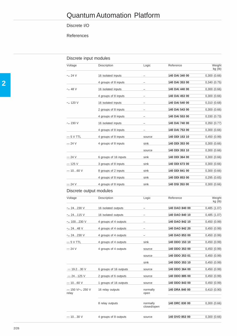
Discrete input modules
Voltage Description Logic Reference Weightkg (Ib)
c 24 V 16 isolated inputs – 140 DAI 340 00 0,300 (0.66)
4 groups of 8 inputs – 140 DAI 353 00 0,340 (0.75)
c 48 V 16 isolated inputs – 140 DAI 440 00 0,300 (0.66)
4 groups of 8 inputs – 140 DAI 453 00 0,300 (0.66)
c 120 V 16 isolated inputs – 140 DAI 540 00 0,310 (0.68)
2 groups of 8 inputs – 140 DAI 543 00 0,300 (0.66)
4 groups of 8 inputs – 140 DAI 553 00 0,330 (0.73)
c 230 V 16 isolated inputs – 140 DAI 740 00 0,350 (0.77)
4 groups of 8 inputs – 140 DAI 753 00 0,300 (0.66)
a 5 V TTL 4 groups of 8 inputs source 140 DDI 153 10 0,450 (0.99)
a 24 V 4 groups of 8 inputs sink 140 DDI 353 00 0,300 (0.66)
source 140 DDI 353 10 0,300 (0.66)
a 24 V 6 groups of 16 inputs sink 140 DDI 364 00 0,300 (0.66)
a 125 V 3 groups of 8 inputs sink 140 DDI 673 00 0,300 (0.66)
a 10…60 V 8 groups of 2 inputs sink 140 DDI 841 00 0,300 (0.66)
4 groups of 8 inputs sink 140 DDI 853 00 0,295 (0.65)
a 24 V 4 groups of 8 inputs sink 140 DSI 353 00 0,300 (0.66)
Discrete output modules
Voltage Description Logic Reference Weightkg (Ib)
c 24…230 V 16 isolated outputs – 140 DAO 840 00 0,485 (1.07)
c 24…115 V 16 isolated outputs – 140 DAO 840 10 0,485 (1.07)
c 100…230 V 4 groups of 4 outputs – 140 DAO 842 10 0,450 (0.99)
c 24…48 V 4 groups of 4 outputs – 140 DAO 842 20 0,450 (0.99)
c 24…230 V 4 groups of 4 outputs – 140 DAO 853 00 0,450 (0.99)
a 5 V TTL 4 groups of 4 outputs sink 140 DDO 153 10 0,450 (0.99)
a 24 V 4 groups of 4 outputs source 140 DDO 353 00 0,450 (0.99)
source 140 DDO 353 01 0,450 (0.99)
sink 140 DDO 353 10 0,450 (0.99)
a 19.2…30 V 6 groups of 16 outputs source 140 DDO 364 00 0,450 (0.99)
a 24…125 V 2 groups of 6 outputs source 140 DDO 885 00 0,450 (0.99)
a 10…60 V 1 groups of 16 outputs source 140 DDO 843 00 0,450 (0.99)
a 150 V/c 250 V 16 relay outputs normally 140 DRA 840 00 0,410 (0.90)relay open
8 relay outputs normally 140 DRC 830 00 0,300 (0.66)closed/open
a 10…30 V 4 groups of 8 outputs source 140 DVO 853 00 0,300 (0.66)

2/27
2
Quantum Automation PlatformDiscrete I/O
References (continued)
Discrete combination I/O modules
Number of Number of Number of Reference Weightinput/output input output kg (Ib)
24 2 groups of 2 groups of 140 DAM 590 00 0,450 (0.99)8 inputs 4 outputc 125 V c 125 V
2 groups of 2 groups of 140 DDM 390 00 0,300 (0.66)8 inputs (1) 4 output (1)a 24 V a 24 V
8 1 group of 1 group of 140 DDM 690 00 0,300 (0.66)4 inputs(1) 4 isolated outputs (2)a 125 V a 125 V
Accessories
Description Quantity Reference Weightkg (Ib)
Terminal block, 40 points – 140 XTS 002 00 0,150(required for all modules)
Dummy module without terminal block – 140 XCP 500 00 –
Dummy module with cover – 140 XCP 510 00 –
Jumper kit for terminal block 12 140 XCP 600 00 –
Discrete input simulator, 16 switches – 140 XSM 002 00 –for the DAI 540 00 and DAI 740 00
Field I/O Power Connector – 140 XTS 005 00 0,150 (0.33)(IP20 rated)
Connecting cables for I/O modules fitted with HE 10 connectors
Description Use Lenght Section Reference Weightkg
Connecting 2 HE 10 0.5 m 0.324 mm2 TSX CDP 053 0,085cables connectors
for Telefast 2system 1 m 0.324 mm2 TSX CDP 103 0,150
2 m 0.324 mm2 TSX CDP 203 0,280
3 m 0.324 mm2 TSX CDP 303 0,410
5 m 0.324 mm2 TSX CDP 503 0,670
Spare parts
Description Quantity Reference Weightkg
Coding kit for terminal block 60 140 XCP 200 00 –
(1) Sink.(2) Sink or source.
2/28
2 2
1
4
3
6
5
8
7
10
9
12
11
14
13
16
15
18
17
20
19
22
21
24
23
26
25
28
27
30
29
32
31
34
33
36
35
38
37
40
39
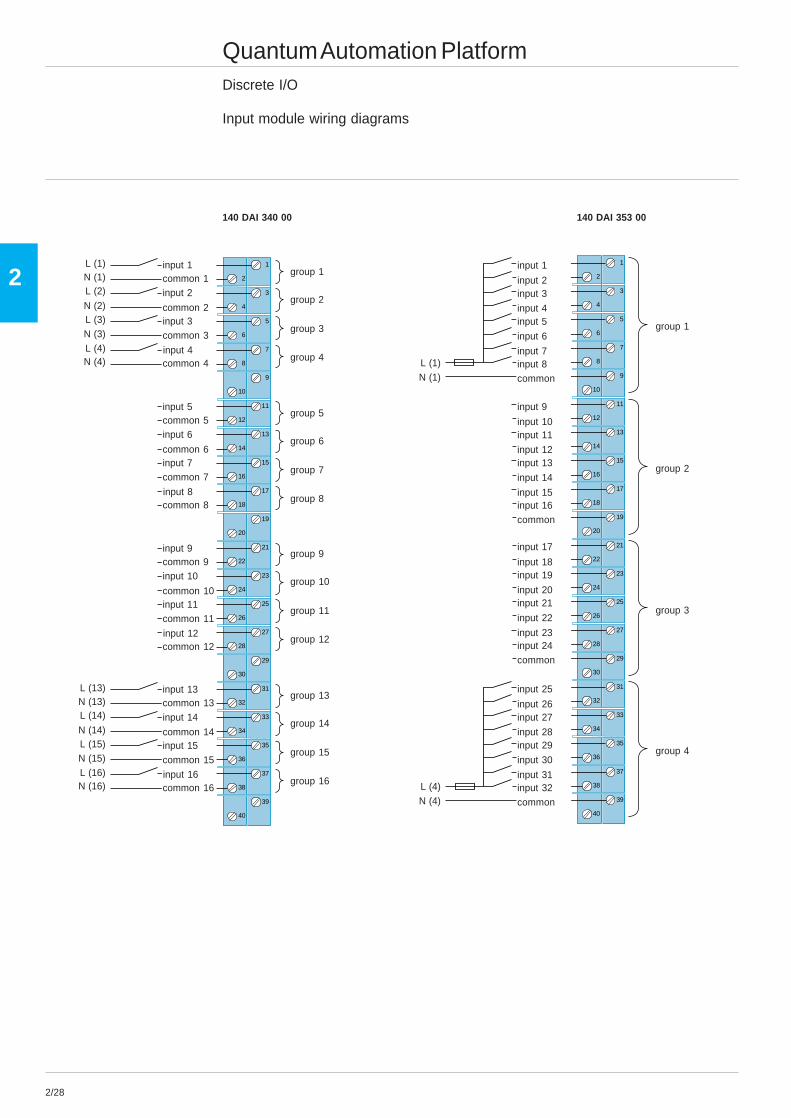
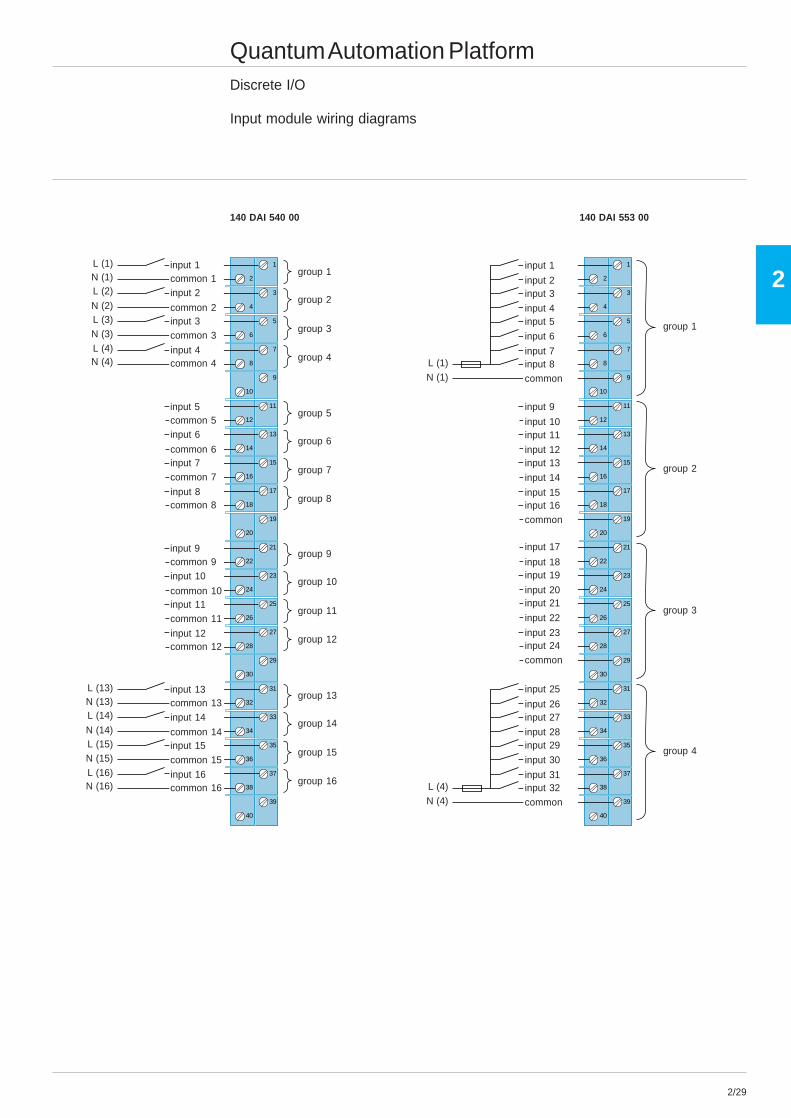
Quantum Automation PlatformDiscrete I/O
Input module wiring diagrams
140 DAI 340 00 140 DAI 353 00
2
1
4
3
6
5
8
7
10
9
12
11
14
13
16
15
18
17
20
19
22
21
24
23
26
25
28
27
30
29
32
31
34
33
36
35
38
37
40
39
L (13)N (13)L (14)
N (14)L (15)N (15)L (16)N (16)
group 1
input 13common 13input 14
common 14
common 16
input 15common 15
input 16
group 2
group 3
group 4
group 5
group 6
group 7
group 8
group 9
group 10
group 11
group 12
group 13
group 14
group 15
group 16
input 9common 9input 10
common 10
common 12
input 11common 11
input 12
input 5common 5input 6
common 6
common 8
input 7common 7
input 8
L (1)N (1)L (2)
N (2)L (3)N (3)L (4)N (4)
input 1common 1input 2
common 2
common 4
input 3common 3
input 4
L (4)N (4)
group 1
input 25
input 26input 27
input 28
input 32
input 29
input 30
input 31
group 2
group 3
group 4
common
input 17
input 18input 19
input 20
input 24
input 21
input 22
input 23
common
input 9
input 10input 11
input 12
input 16
input 13
input 14
input 15
common
L (1)N (1)
input 1
input 2input 3
input 4
input 8
input 5
input 6
input 7
common
2/29
2
Quantum Automation PlatformDiscrete I/O
Input module wiring diagrams
140 DAI 540 00 140 DAI 553 00
2
1
4
3
6
5
8
7
10
9
12
11
14
13
16
15
18
17
20
19
22
21
24
23
26
25
28
27
30
29
32
31
34
33
36
35
38
37
40
39
L (13)N (13)L (14)
N (14)L (15)N (15)L (16)N (16)
group 1
input 13common 13input 14
common 14
common 16
input 15common 15
input 16
group 2
group 3
group 4
group 5
group 6
group 7
group 8
group 9
group 10
group 11
group 12
group 13
group 14
group 15
group 16
input 9common 9input 10
common 10
common 12
input 11common 11
input 12
input 5common 5input 6
common 6
common 8
input 7common 7
input 8
L (1)N (1)L (2)
N (2)L (3)N (3)L (4)N (4)
input 1common 1input 2
common 2
common 4
input 3common 3
input 4
2
1
4
3
6
5
8
7
10
9
12
11
14
13
16
15
18
17
20
19
22
21
24
23
26
25
28
27
30
29
32
31
34
33
36
35
38
37
40
39
L (4)N (4)
group 1
input 25
input 26input 27
input 28
input 32
input 29
input 30
input 31
group 2
group 3
group 4
common
input 17
input 18input 19
input 20
input 24
input 21
input 22
input 23
common
input 9
input 10input 11
input 12
input 16
input 13
input 14
input 15
common
L (1)N (1)
input 1
input 2input 3
input 4
input 8
input 5
input 6
input 7
common

2/30
2
Quantum Automation PlatformDiscrete I/O
Input module wiring diagrams
140 DDI 353 00 140 DDI 364 00
2
1
4
3
6
5
8
7
10
9
12
11
14
13
16
15
18
17
20
19
22
21
24
23
26
25
28
27
30
29
32
31
34
33
36
35
38
37
40
39
UB (4)M (4)
group 1
input 25
input 26input 27
input 28
input 32
input 29
input 30
input 31
group 2
group 3
group 4
M 4
input 17
input 18input 19
input 20
input 24
input 21
input 22
input 23
M 3
input 9
input 10input 11
input 12
input 16
input 13
input 14
input 15
M 2
UB (1)M (1)
input 1
input 2input 3
input 4
input 8
input 5
input 6
input 7
M 1
A
4
6
10
12
8
0
2
1415
5
7
11
13
9
1
3
+–
2
43
6
8
12
14
10
5
7
11
13
9
2019
1615
17 18
1

2/31
2
Quantum Automation PlatformDiscrete I/O
Input module wiring diagrams
140 DDI 841 00 140 DSI 353 00
2
1
4
3
6
5
8
7
10
9
12
11
14
13
16
15
18
17
20
19
22
21
24
23
26
25
28
27
30
29
32
31
34
33
36
35
38
37
40
39
group 1
group 2
M (1)UB (1)
input 1input 2M 1
common 1
common 2
input 3input 4
M 2
input 5input 6M 3
common 3
common 4
input 7input 8
M 4
input 9input 10M 5
common 5
common 6
input 11input 12
M 6
input 13input 14M 7
common 7
common 8
input 15input 16
M 8
group 3
group 4
group 5
group 6
group 7
group 8
M (2)UB (2)
M (7)UB (7)
M (8)UB (8)
2
1
4
3
6
5
8
7
10
9
12
11
14
13
16
15
18
17
20
19
22
21
24
23
26
25
28
27
30
29
32
31
34
33
36
35
38
37
40
39
input 2
input 4
input 6
input 8
input 10
input 12
input 14
input 16
group A ext.supply
group B ext.supply
input 18
input 20
input 22
input 24
group C ext.supply
input 26
input 28
input 30
input 32
group D ext.supply
- input 1
- input 3
- input 5
- input 7
- input 9
- input 11
- input 13
- input 15
group Acommon
group B ext.common
- input 17
- input 19
- input 21
- input 23
group C ext.common
- input 25
- input 27
- input 29
- input 31
group Dcommon

2/32
2
2
1
4
3
6
5
8
7
10
9
12
11
14
13
16
15
18
17
20
19
22
21
24
23
26
25
28
27
30
29
32
31
34
33
36
35
38
37
40
39
1
2
3
4
13
14
15
16
Quantum Automation PlatformDiscrete I/O
Output module wiring diagrams
140 DAO 840 00 140 DAO 842 10
2
1
4
3
6
5
8
7
10
9
12
11
14
13
16
15
18
17
20
19
22
21
24
23
26
25
28
27
30
29
32
31
34
33
36
35
38
37
40
39
1
2
3
4
13
14
15
16
N (13)L (13)N (14)
L (14)N (15)L (15)N (16)L (16)
group 1
output 13L 13output 14
L 14
L 16
output 15L 15
output 16
group 2
group 3
group 4
group 5
group 6
group 7
group 8
group 9
group 10
group 11
group 12
group 13
group 14
group 15
group 16
output 9L 9output 10
L 10
L 12
output 11L 11
output 12
output 5L 5output 6
L 6
L 8
output 7L 7
output 8
N (1)L (1)N (2)
L (2)N (3)L (3)N (4)L (4)
output 1L 1output 2
L 2
L 4
output 3L 3
output 4
L (4)N (4)
group 1
group 2
group 3
group 4
common
common
L (1)N (1)
output 1
output 2
output 3
output 4
commonLoutput 5
output 6
output 7
output 8
L
L
output 9
output 10
output 11
output 12
commonL
output 13
output 14
output 15
output 16
2/33
2
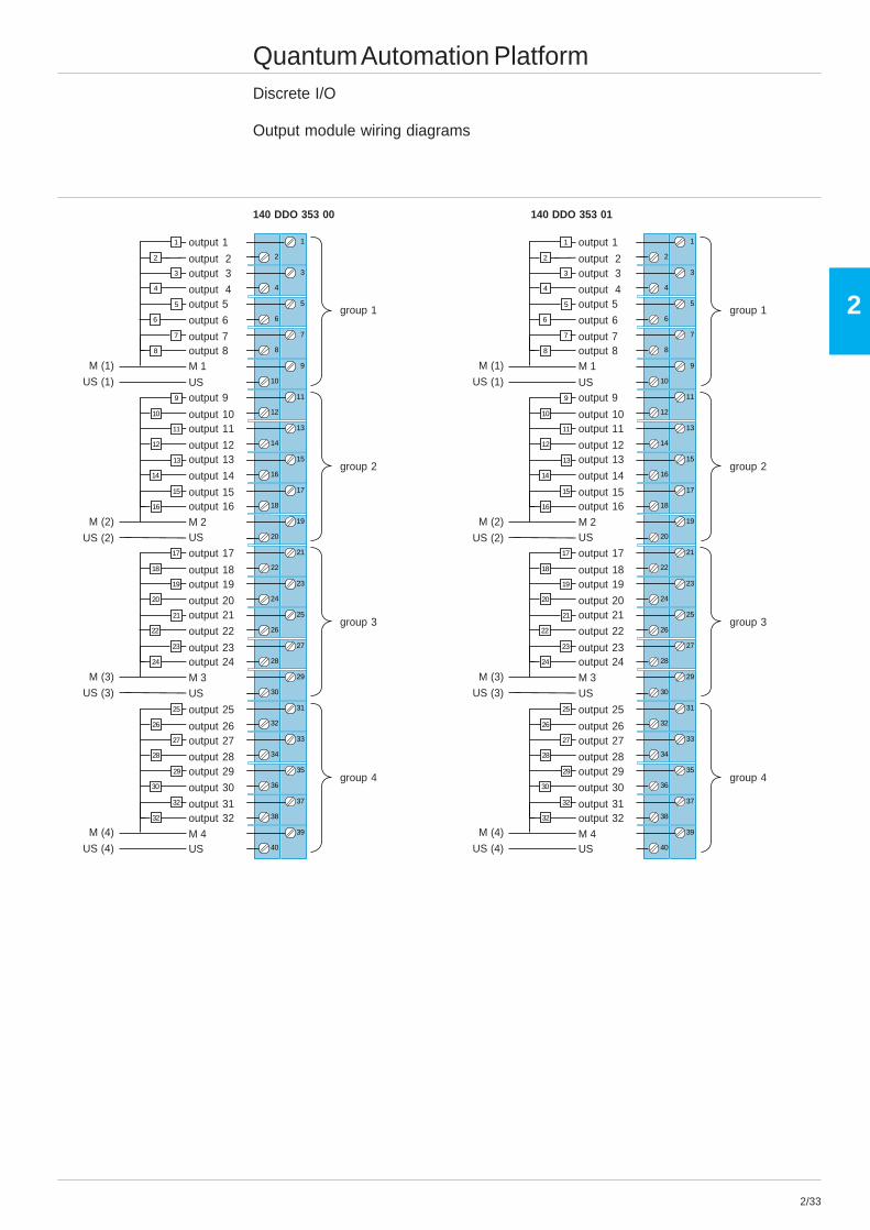
Quantum Automation PlatformDiscrete I/O
Output module wiring diagrams
140 DDO 353 00 140 DDO 353 01
2
1
4
3
6
5
8
7
10
9
12
11
14
13
16
15
18
17
20
19
22
21
24
23
26
25
28
27
30
29
32
31
34
33
36
35
38
37
40
39
1
2
3
7
5
4
6
8
9
10
11
15
13
12
14
16
17
18
19
23
21
20
22
24
25
26
27
32
29
28
30
32
group 1
output 25
output 26output 27
output 28
output 32
output 29
output 30
output 31
group 2
group 3
group 4
M 4
output 17
output 18output 19
output 20
output 24
output 21
output 22
output 23
M 3
output 9
output 10output 11
output 12
output 16
output 13
output 14
output 15
M 2
US (1)
M (1)
output 1
output 2output 3
output 4
output 8
output 5
output 6
output 7
M 1
US
US (2)
M (2)US
US (3)
M (3)
US
US (4)
M (4)
US
2
1
4
3
6
5
8
7
10
9
12
11
14
13
16
15
18
17
20
19
22
21
24
23
26
25
28
27
30
29
32
31
34
33
36
35
38
37
40
39
1
2
3
7
5
4
6
8
9
10
11
15
13
12
14
16
17
18
19
23
21
20
22
24
25
26
27
32
29
28
30
32
group 1
output 25
output 26output 27
output 28
output 32
output 29
output 30
output 31
group 2
group 3
group 4
M 4
output 17
output 18output 19
output 20
output 24
output 21
output 22
output 23
M 3
output 9
output 10output 11
output 12
output 16
output 13
output 14
output 15
M 2
US (1)
M (1)
output 1
output 2output 3
output 4
output 8
output 5
output 6
output 7
M 1
US
US (2)
M (2)US
US (3)
M (3)
US
US (4)
M (4)
US
2/34
2
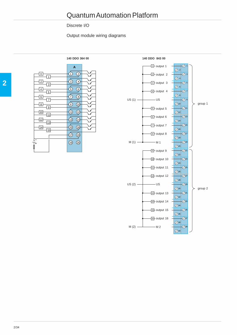
Quantum Automation PlatformDiscrete I/O
Output module wiring diagrams
140 DDO 364 00 140 DDO 843 00
2
1
4
3
6
5
8
7
10
9
12
11
14
13
16
15
18
17
20
19
22
21
24
23
26
25
28
27
30
29
32
31
34
33
36
35
38
37
40
39
1
2
4
3
5
6
8
7
9
10
12
11
13
14
16
15
group 1
group 2
M 1
US (1)
M (1)
US
output 1
output 2
output 3
output 4
output 8
output 5
output 6
output 7
M 2
US (2)
M (2)
US
output 9
output 10
output 11
output 12
output 16
output 13
output 14
output 15
A
4
6
10
12
8
0
2
1415
5
7
11
13
9
1
3
–+
2
43
6
8
12
14
10
5
7
11
13
9
20
1615
17 18
1
19
2/35
2
2
1
4
3
6
5
8
7
10
9
12
11
14
13
16
15
18
17
20
19
22
21
24
23
26
25
28
27
30
29
32
31
34
33
36
35
38
37
40
39
+–
+ –
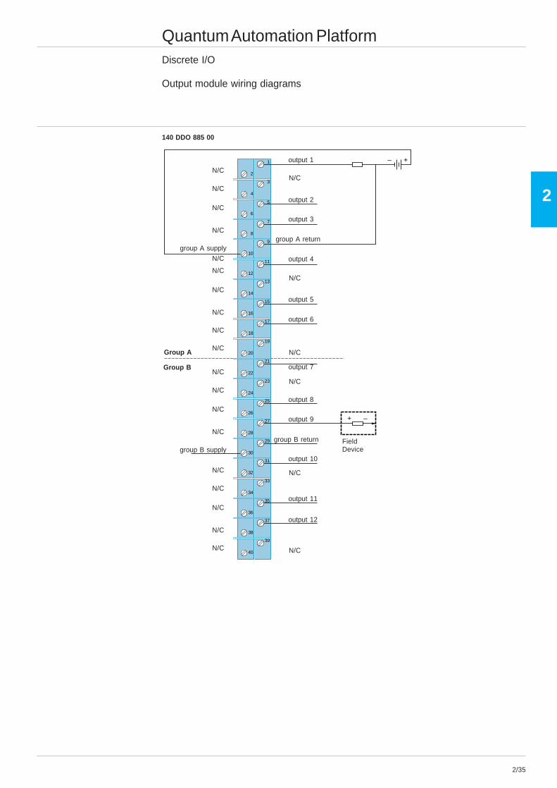
Quantum Automation PlatformDiscrete I/O
Output module wiring diagrams
140 DDO 885 00
group A return
output 1
output 2
output 3
output 4
output 5
output 6
N/C
N/C
output 7
output 8
N/C
group B return
output 10
N/C
N/C
output 12
output 11
output 9
FieldDevice
N/CN/C
N/C
N/C
N/C
group A supply
N/C
N/C
N/C
N/C
N/C
Group A N/C
N/C
N/C
N/C
N/C
group B supply
Group B
N/C
N/C
N/C
N/C
N/C
2/36
2
Quantum Automation PlatformDiscrete I/O
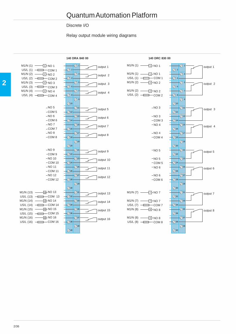
Relay output module wiring diagrams
140 DRA 840 00 140 DRC 830 00
M1/N (1)
output 16
2
1
4
3
6
5
8
7
10
9
12
11
14
13
16
15
18
17
20
19
22
21
24
23
26
25
28
27
30
29
32
31
34
33
36
35
38
37
40
39
1
2
3
4
13
14
15
16
US/L (1)M1/N (2)
US/L (2)M1/N (3)
US/L (3)M1/N (4)US/L (4)
M1/N (13)US/L (13)M1/N (14)US/L (14)M1/N (15)US/L (15)M1/N (16)
US/L (16)
output 15
output 14
output 13
output 12
output 11
output 10
output 9
output 8
output 7
output 6
output 5
output 4
output 3
output 2
output 1NO 1
COM 1NO 2COM 2
COM 4
NO 3
COM 3NO 4
NO 5
COM 5NO 6COM 6
COM 8
NO 7
COM 7NO 8
NO 9
COM 9NO 10COM 10
COM 12
NO 11
COM 11NO 12
NO 13
COM 13NO 14COM 14
COM 16
NO 15
COM 15NO 16
2
1
4
3
6
5
8
7
10
9
12
11
14
13
16
15
18
17
20
19
22
21
24
23
26
25
28
27
30
29
32
31
34
33
36
35
38
37
40
39
1
1
2
2
7
7
8
8
M1/N (1)
M1/N (1)
US/L (1)M1/N (2)
M1/N (2)US/L (2)
M1/N (7)
M1/N (7)US/L (7)M1/N (8)
M1/N (8)
US/L (8)
output 8
output 7
output 6
output 5
output 4
output 3
output 2
output 1NO 1
NO 1COM 1
COM 2
NO 2
NO 2
NO 3
NO 3COM 3
COM 4
NO 4
NO 4
NO 5
NO 5COM 5
COM 6
NO 6
NO 6
NO 7
NO 7COM 7
COM 8
NO 8
NO 8
2/37
2
Quantum Automation PlatformDiscrete I/O
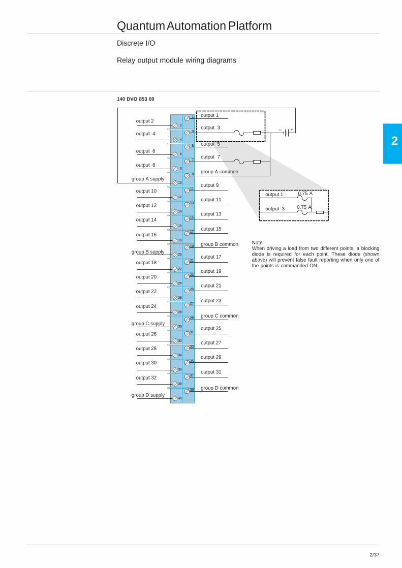
Relay output module wiring diagrams
140 DVO 853 00
NoteWhen driving a load from two different points, a blockingdiode is required for each point. These diode (shownabove) will prevent false fault reporting when only one ofthe points is commanded ON.
2
1
4
3
6
5
8
7
10
9
12
11
14
13
16
15
18
17
20
19
22
21
24
23
26
25
28
27
30
29
32
31
34
33
36
35
38
37
40
39
+–
output 31
output 29
output 27
output 25
output 23
output 21
output 19
output 17
output 15
output 13
output 11
output 9
output 7
output 5
output 3
output 1
output 32
output 30
output 28
output 26
output 24
output 22
output 20
output 18
output 16
output 14
output 12
output 10
output 8
output 6
output 4
output 2
group A commongroup A supply
group B common
group C common
group D commongroup D supply
group B supply
group C supply
output 3
output 1
0.75 A
0.75 A
2/38
2
2
1
4
3
6
5
8
7
10
9
12
11
14
13
16
15
18
17
20
19
22
21
24
23
26
25
28
27
30
29
32
31
34
33
36
35
38
37
40
39
1
2
4
3
5
6
8
7
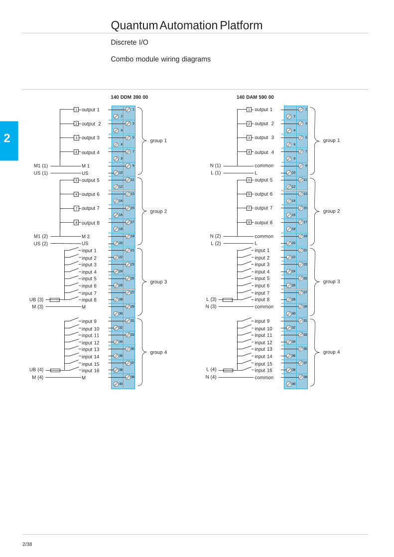
Quantum Automation PlatformDiscrete I/O
Combo module wiring diagrams
140 DDM 390 00 140 DAM 590 00
group 1
input 9
input 10input 11
input 12
input 16
input 13
input 14
input 15
group 2
group 3
group 4
M
input 1
input 2input 3
input 4
input 8
input 5
input 6
input 7
M
output 5
output 6
output 7
output 8
M 2
US (1)
M1 (1)
output 1
output 2
output 3
output 4
M 1
US
US (2)
M1 (2)US
UB (3)M (3)
UB (4)
M (4)
2
1
4
3
6
5
8
7
10
9
12
11
14
13
16
15
18
17
20
19
22
21
24
23
26
25
28
27
30
29
32
31
34
33
36
35
38
37
40
39
1
2
3
4
5
6
7
8
group 1
input 9
input 10input 11
input 12
input 16
input 13
input 14
input 15
group 2
group 3
group 4
common
input 1
input 2input 3
input 4
input 8
input 5
input 6
input 7
common
output 5
output 6
output 7
output 8
common
L (1)
N (1)
output 1
output 2
output 3
output 4
common
L
L (2)
N (2)L
L (3)N (3)
L (4)
N (4)
2/39
2
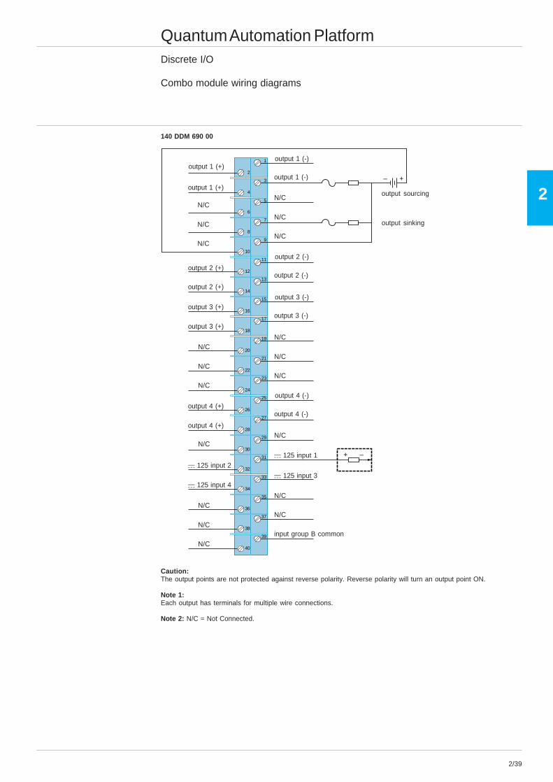
Quantum Automation PlatformDiscrete I/O
Combo module wiring diagrams
140 DDM 690 00
Caution:The output points are not protected against reverse polarity. Reverse polarity will turn an output point ON.
Note 1:Each output has terminals for multiple wire connections.
Note 2: N/C = Not Connected.
2
1
4
3
6
5
8
7
10
9
12
11
14
13
16
15
18
17
20
19
22
21
24
23
26
25
28
27
30
29
32
31
34
33
36
35
38
37
40
39
+–
+ –
output sourcing
input group B common
output 1 (+)
output 1 (+)
N/C
N/C
N/C
output 2 (+)
output 2 (+)
output 3 (+)
output 3 (+)
N/C
N/C
N/C
output 4 (+)
output 4 (+)
N/C
a 125 input 2
a 125 input 4
N/C
N/C
N/C
output sinking
output 1 (-)
output 1 (-)
N/C
N/C
N/C
output 2 (-)
output 2 (-)
output 3 (-)
output 3 (-)
N/C
N/C
N/C
output 4 (-)
output 4 (-)
N/C
a 125 input 1
a 125 input 3
N/C
N/C

2/40
2
Presentation
Quantum Automation Platform Telefast® 2 pre-wired systemConnector cables for Quantum PLCs1-2 Cabled connectors combine a standard terminal block equipped with screw terminals, two multicore (AWG 22)cables and two 20-way HE 10 connectors. Two cabled connectors are available for the Quantum range and twoothers for the 984-A120-Compact range.The 4 products have the following functions :- ABF-M32Hpp0 1 for Quantum relay inputs or outputs, with 2 x HE 10 connectors each integrating 16 channels.- ABF-M32Hpp1 2 for outputs directly connected to the Quantum, with 2 x HE 10 connectors each integrating 16channels and an external power supply with a direct connection to the output terminal marked 1.- ABF-M16Hpp0 for 984-A120-Compact inputs or relay outputs, with 1 x HE 10 connector each integrating 16 channels.- ABF-M16Hpp1 for 984-A120-Compact directly connected outputs, with 2 x HE 10 connectors each integrating 8 channels.
2 The splitter sub-base ABE-7ACC02 may be used to connect sub-bases with 8-channel modularity.
3 A single type of cable equipped with 20-way HE 10 connectors irrespective of the 8, 12 or 16-channel modularity.The HE 10 connectors may be moulded (TSX-CDPppp) or self-perforating (ABF-H20Hppp).
5 8 and 16-channel sub-bases from the Telefast 2 range.(1) The c 24 V power supply is connected using Telefast 2 sub-bases only. The c 0 V connections must be equipotential.
0 1 2 3 4 5 6 7 8 9 10 11 12 13 14 15
1
25
5
5
55
3
4
4
0 1 2 3 4 5 6 7 8 9 10 11 12 13 14 15
0 1 2 3 4 5 6 7 8 9 10 11 12 13 14 15
01
23
45
67
89
1011
1213
1415
8165
75
Compatibility
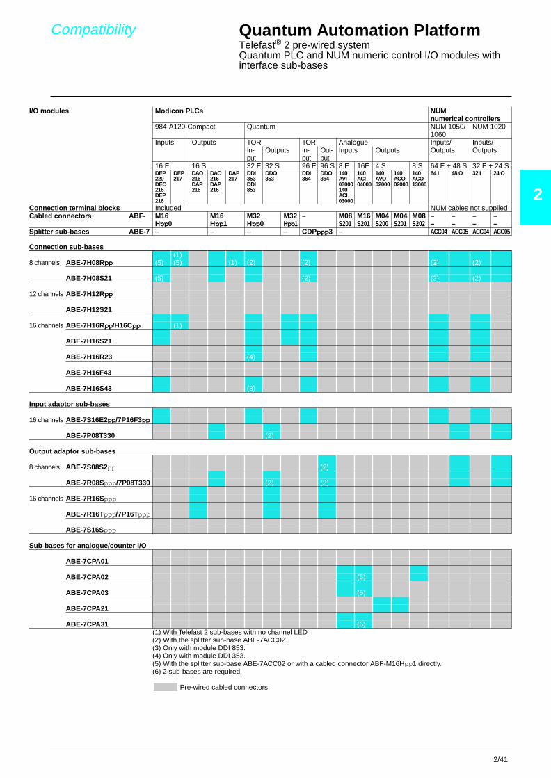
Quantum Automation PlatformTelefast® 2 pre-wired systemQuantum PLC and NUM numeric control I/O modules with interface sub-bases2
(1) With Telefast 2 sub-bases with no channel LED.(2) With the splitter sub-base ABE-7ACC02.(3) Only with module DDI 853.(4) Only with module DDI 353.(5) With the splitter sub-base ABE-7ACC02 or with a cabled connector ABF-M16Hpp1 directly.(6) 2 sub-bases are required.
I/O modules Modicon PLCs NUM numerical controllers
984-A120-Compact Quantum NUM 1050/1060
NUM 1020
Inputs Outputs TOR TOR Analogue Inputs/Outputs
Inputs/OutputsIn-
putOutputs In-
putOut-put
Inputs Outputs
16 E 16 S 32 E 32 S 96 E 96 S 8 E 16E 4 S 8 S 64 E + 48 S 32 E + 24 SDEP220DEO216DEP216
DEP217
DAO216DAP216
DAO216DAP216
DAP217
DDI353DDI853
DDO353
DDI364
DDO364
140AVI03000140ACI03000
140 ACI04000
140AVO02000
140ACO02000
140ACO13000
64 I 48 O 32 I 24 O
Connection terminal blocks Included NUM cables not suppliedCabled connectors ABF- M16
Hpppppppp0M16Hpppppppp1
M32Hpppppppp0
M32Hpppppppp1
– M08S201
M16 S201
M04S200
M04S201
M08 S202
– – – –– – – –
Splitter sub-bases ABE-7 – – – – CDPpppppppppppp3 – ACC04 ACC05 ACC04 ACC05
Connection sub-bases(1)
8 channels ABE-7H08Rpppppppp (5) (5) (1) (2) (2) (2) (2)
ABE-7H08S21 (5) (2) (2) (2)
12 channels ABE-7H12Rpppppppp
ABE-7H12S21
16 channels ABE-7H16Rpppppppp/H16Cpppppppp (1)
ABE-7H16S21
ABE-7H16R23 (4)
ABE-7H16F43
ABE-7H16S43 (3)
Input adaptor sub-bases
16 channels ABE-7S16E2pppppppp/7P16F3pppppppp
ABE-7P08T330 (2)
Output adaptor sub-bases
8 channels ABE-7S08S2pp (2)
ABE-7R08Sppp/7P08T330 (2) (2)
16 channels ABE-7R16Sppp
ABE-7R16Tppp/7P16Tppp
ABE-7S16Sppp
Sub-bases for analogue/counter I/O
ABE-7CPA01
ABE-7CPA02 (6)
ABE-7CPA03 (6)
ABE-7CPA21
ABE-7CPA31 (6)
Pre-wired cabled connectors
2/41

2/42
2
References
Quantum Automation PlatformTelefast® 2 pre-wired systemPassive connection sub-basesPassive connection sub-bases for discrete signals
"Low cost" sub-basesFunction No. No. of terminals For PLCs Length Type Reference Weight
of per on of PLC ofchan- chan- row connection connectionnels nel number cable
m kg
Input 16 1 2 Modicon 1 Screw ABE-7H20E100 0.330or Micro/PremiumOutput
2 Screw ABE-7H20E200 0.410
3 Screw ABE-7H20E300 0.480
Siemens S7 1.5 Screw ABE-7H32E150 0.360
3 Screw ABE-7H32E300 0.460
"Miniature" sub-basesFunction No. No. of terminals LED Polarity Type Reference Weight
of per on per distribution ofchan- chan- row chan- connectionnels nel number nel kg
Input 16 1 1 No No Screw ABE-7H16C10 0.160orOutput
Yes No Screw ABE-7H16C11 0.160
2 2 Yes 0 or 24 V Screw ABE-7H16C21 0.205
3 3 Yes 0 and 24 V Screw ABE-7H16C31 0.260
Input 16 1 1 Yes No Screw ABE-7H16CM11 0.160andOutput (1)
2 2 Yes 0 or 24 V Screw ABE-7H16CM21 0.200
(1) 8 I + 8 Q : these products have 2 commons connections which enable inputs and outputs to be connected to the samesub-base at the same time.
ABE-7H20Epppppppppppp
ABE-7H16C21
8164
62
ABE-7H16CM21
8164
63
References
Quantum Automation PlatformTelefast® 2 pre-wired systemPassive connection sub-bases2
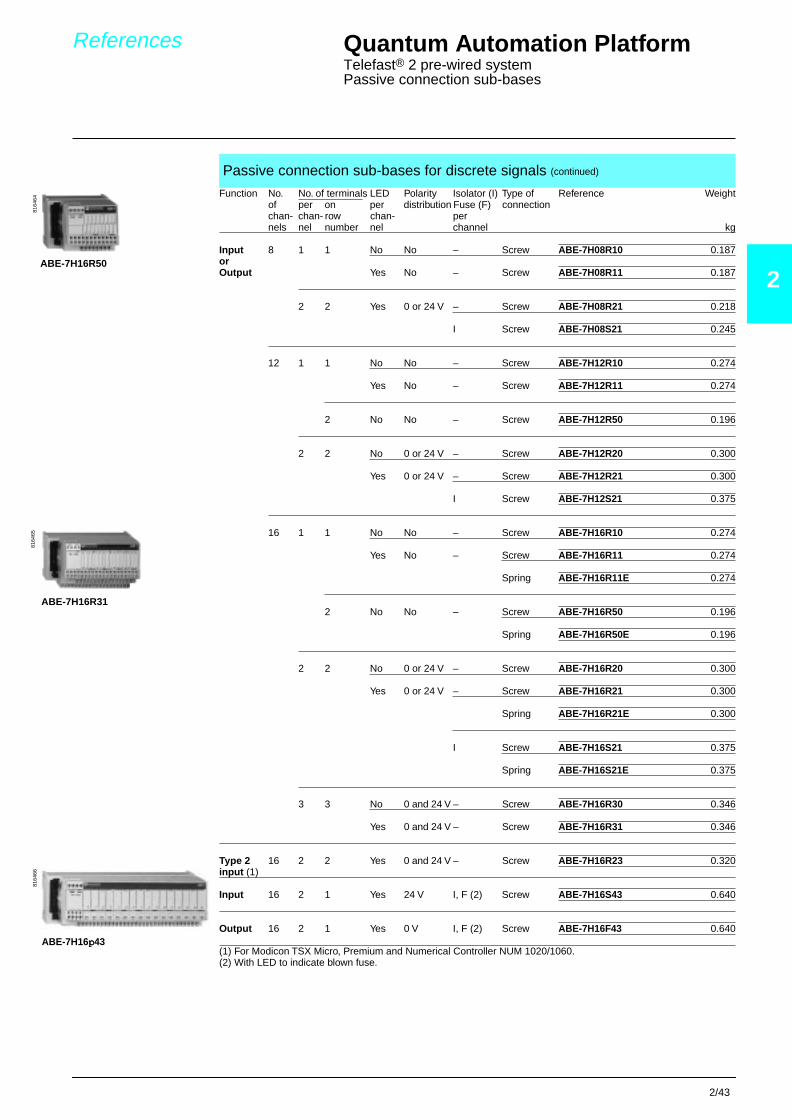
(2) With LED to indicate blown fuse.
Passive connection sub-bases for discrete signals (continued)
Function No. No. of terminals LED Polarity Isolator (I) Type of Reference Weightof per on per distribution Fuse (F) connectionchan- chan- row chan- pernels nel number nel channel kg
Input 8 1 1 No No – Screw ABE-7H08R10 0.187orOutput Yes No – Screw ABE-7H08R11 0.187
2 2 Yes 0 or 24 V – Screw ABE-7H08R21 0.218
I Screw ABE-7H08S21 0.245
12 1 1 No No – Screw ABE-7H12R10 0.274
Yes No – Screw ABE-7H12R11 0.274
2 No No – Screw ABE-7H12R50 0.196
2 2 No 0 or 24 V – Screw ABE-7H12R20 0.300
Yes 0 or 24 V – Screw ABE-7H12R21 0.300
I Screw ABE-7H12S21 0.375
16 1 1 No No – Screw ABE-7H16R10 0.274
Yes No – Screw ABE-7H16R11 0.274
Spring ABE-7H16R11E 0.274
2 No No – Screw ABE-7H16R50 0.196
Spring ABE-7H16R50E 0.196
2 2 No 0 or 24 V – Screw ABE-7H16R20 0.300
Yes 0 or 24 V – Screw ABE-7H16R21 0.300
Spring ABE-7H16R21E 0.300
I Screw ABE-7H16S21 0.375
Spring ABE-7H16S21E 0.375
3 3 No 0 and 24 V – Screw ABE-7H16R30 0.346
Yes 0 and 24 V – Screw ABE-7H16R31 0.346
Type 2 16 2 2 Yes 0 and 24 V – Screw ABE-7H16R23 0.320input (1)
Input 16 2 1 Yes 24 V I, F (2) Screw ABE-7H16S43 0.640
Output 16 2 1 Yes 0 V I, F (2) Screw ABE-7H16F43 0.640
(1) For Modicon TSX Micro, Premium and Numerical Controller NUM 1020/1060.
8164
6481
6465
8164
66
ABE-7H16R50
ABE-7H16R31
ABE-7H16pppp43
2/43

2/44
2
References
Quantum Automation PlatformTelefast® 2 pre-wired systemConnection sub-bases with soldered relays and plug-in terminal blocksSub-bases with soldered solid state inputs, plug-in terminal blocks
Number No. of Isolation Voltage Type Reference Weightof terminals PLC/application ofchannels per channel V connection kg
16 2 Yes c 24 Screw ABE-7S16E2B1 0.370
Spring ABE-7S16E2B1E 0.370
c 48 Screw ABE-7S16E2E1 0.370
Spring ABE-7S16E2E1E 0.370
a 48 Screw ABE-7S16E2E0 0.386
Spring ABE-7S16E2E0E 0.386
a 110 Screw ABE-7S16E2F0 0.397
Spring ABE-7S16E2F0E 0.397
a 230 Screw ABE-7S16E2M0 0.407
Spring ABE-7S16E2M0E 0.407
Sub-bases with soldered solid state outputs, plug-in terminal blocks
No. of Isolation Output Output Fault Type Reference Weightchannels PLC/ voltage current detection of
application V A signal (1) connection kg
8 No c 24 0.5 Yes (2) Screw ABE-7S08S2B0 0.252
Spring ABE-7S08S2B0E 0.252
2 Yes (2) Screw ABE-7S08S2B1 0.448
Spring ABE-7S08S2B1E 0.448
16 No c 24 0.5 Yes (2) Screw ABE-7S16S2B0 0.405
Spring ABE-7S16S2B0E 0.405
No Screw ABE-7S16S1B2 0.400
Spring ABE-7S16S1B2E 0.400
Sub-bases with soldered electromechanical relays, plug-in terminal blocks
No. of Relay No. of Output Polarity Type Reference Weightchannels width contacts current distribution/ of
mm A application connection kg
8 5 1 “N/O” 2 Contact common Screw ABE-7R08S111 0.244per groupof 4 channels Spring ABE-7R08S111E 0.244
Bistable 2 Volt-free Screw ABE-7R08S216 0.250
Spring ABE-7R08S216E 0.250
10 1 “N/O” 5 Volt-free Screw ABE-7R08S210 0.352
Spring ABE-7R08S210E 0.352
16 5 1 “N/O” 2 Contact common Screw ABE-7R16S11 0.352per groupof 8 channels Spring ABE-7R16S111E 0.352
10 1 “N/O” 5 Volt-free Screw ABE-7R16S210 0.547Spring ABE-7R16S210E 0.547
Common per Screw ABE-7R16S212 0.547group of 8 chan. Spring ABE-7R16S212E 0.547on both poles
(1) A fault on a sub-base output Qn will set PLC output Qn to safety mode which will be detected by the PLC.(2) Can only be used with modules with protected outputs.
ABE-7S16E2pp
ABE-7R08S216

References
Quantum Automation PlatformTelefast® 2 pre-wired systemPlug-in relay sub-bases2
Sub-bases for plug-in solid state input relays (1)
No. of Term- For Isolation Input Type Reference Weightchan- inals/ relay PLC/ connection ofnels channel type application connection kg
16 2 ABS-7E Yes Volt-free Screw ABE-7P16F310 0.850ABR-7 (2)
Spring ABE-7P16F310E 0.850
Polarity distribution Screw ABE-7P16F312 0.850
Output sub-bases, equipped with plug-in electromechanical relays (3)
No. of Relay Type No. and Polarity Reference Weightchan- width of type of distribution/nels mm relay contacts application kg
16 5 ABR-7S11 1 N/O Contact common ABE-7R16T111 0.600per group of 4 channels
Contact common ABE-7R16M111 (4) 0.600per group of 4 output channels+ 2 input common terminals
10 ABR-7S21 1 N/O Volt-free ABE-7R16T210 0.735
Common ABE-7R16T212 0.730on both poles (5)
ABR-7S23 1 C/O Contact common (5) ABE-7R16T231 0.730
Volt-free ABE-7R16T230 0.775
12 ABR-7S33 1 C/O Volt-free ABE-7R16T330 1.300
Common ABE-7R16T332 1.200on both poles (6)
ABR-7S37 2 C/O Volt-free ABE-7R16T370 1.300
(1) Not equipped with relays(2) Sub-bases may be equipped with electromechanical relays (please consult your Regional Sales Office).(3) Both technologies (electromechanical and solid state) may be combined on the same sub-base.(4) 2 connection methods are available, enabling inputs and outputs to be connected to the same sub-base at the sametime. (5) Per group of 8 channels.(6) Per group of 4 channels.
ABE-7R16M111
8164
71
ABE-7R16T210
8164
69
2/45

2/46
2
References
Quantum Automation PlatformTelefast® 2 pre-wired systemPlug-in relay sub-basesSub-bases for solid state and/or electromechanical output relays, plug-in (1)
No. of Relay For Isolator Fuse Polarity Type Reference Weightchan- width relay per per distribution/ ofnels type channel channel application connection
mm kg
16 5 ABR-7S11 No No Contact common ABE-7P16T111 0.550ABS-7SC1B per group of 4 channels
Contact common ABE-7P16M111 (2) 0.550per group of 4 output channels and 2 commoninput terminals
10 ABR-7S2p No No Volt-free Screw ABE-7P16T210 (3) 0.615ABS-7SA2pABS-7SC2p ABE-7P16T230 (3) 0.655ABE-7ACC20
Spring ABE-7P16T230E (3) 0.655
Yes Volt-free Screw ABE-7P16T214 0.675
No Common Screw ABE-7P16T212 0.615on bothpoles (4)
Yes Common Screw ABE-7P16T215 0.670on bothpoles (4)
8 12 ABR-7S33 No No Volt-free Screw ABE-7P08T330 0.450ABS-7SA3pABS-7SC3ppABE-7ACC21
Spring ABE-7P08T330E 0.450
16 12 ABR-7S33 No No Volt-free Screw ABE-7P16T330 0.900ABS-7SA3pABS-7SC3ppABE-7ACC21
Spring ABE-7P16T330E 0.900
Common Screw ABE-7P16T332 0.900on bothpoles (5)
ABR-7S33 No Yes Volt-free Screw ABE-7P16T334 0.900ABS-7SA3MABS-7SC3EABE-7ACC21
Yes Yes Common Screw ABE-7P16T318 1.000on bothpoles (5)
Spring ABE-7P16T318E 1.000
(1) Not equipped with relays(2) 2 connection methods are available, enabling inputs and outputs to be connected to the same sub-base at the same time.(3) With relay ABR-7S21 for sub-base ABE-7P16T210, with relay ABR-7S23 for sub-base ABE-7P16T230p.(4) Per group of 8 channels.(5) Per group of 4 channels.
ABE-7P16T2pppppppp
8164
73

References
Quantum Automation PlatformTelefast® 2 pre-wired systemPlug-in relays2
(1) See characterics table for specifications of relays in the sub-bases
Plug-in solid state relays (Order in multiples of 4)
Relay Func- Input circuit Output circuit Unit Weightwidth tions Current Nominal Current (1) Nominal reference
voltage voltagemm V A V kg
5 Output c 24 2 c 24 ABS-7SC1B 0.010
10 Output c 24 0.5 c 5…48 ABS-7SC2E 0.016
a 24…240 ABS-7SA2M 0.016
12 Input c 5 TTL c 24 ABS-7EC3AL 0.014
24 Type 2 – c 24 ABS-7EC3B2 0.014
48 Type 2 – c 24 ABS-7EC3E2 0.014
a 50 Hz 48 – c 24 ABS-7EA3E5 0.014
a 60 Hz 110…130 – c 24 ABS-7EA3F5 0.014
230…240 – c 24 ABS-7EA3M5 0.014
Output c 24 2 c 24 ABS-7SC3BA 0.016Self-protected
1.5 c 5…48 ABS-7SC3E 0.016
1.5 a 24…240 ABS-7SA3M 0.016
Plug-in electromechanical relays
Relay Control Output No. of Order in Unit Weightwidth voltage current (1) contacts multiples of referencemm V A (Ith) kg
5 cccc 24 5 1 N/O 4 ABR-7S11 0.005
10 cccc 24 5 1 N/O 4 ABR-7S21 0.008
1 C/O 4 ABR-7S23 0.008
12 cccc 24 10 1 C/O 4 ABR-7S33 0.017
8 2 C/O 4 ABR-7S37 0.017
cccc 48 8 1 C/O 4 ABR-7S33E 0.017
Accessory
Description Reference Weightkg
Extractor for 5 mm miniature relays ABE-7ACC12 0.010
ABS-7SC1B
8164
75
ABR-7S2pppp
8164
76
ABR-7S3pppp
8164
74
2/47
2/48
2
20-way 984-A120 20-wayHE 10 Compact HE 10Terminal no. Channels Term. blk. Channels Terminal no.1 1 3 14 9 12 2 4 15 10 23 3 5 16 11 34 4 6 17 12 45 5 7 18 13 56 6 8 19 14 67 7 9 20 15 78 8 10 21 16 89-10-11-12 NC NC 9-10-11-1213-15-17 c 24 V 1 12 c 24 V 13-15-1714-16-19 c 24 V 2 13 c 24 V 14-16-1918-20 c 0 V 11 22 c 0 V 18-20
1 2
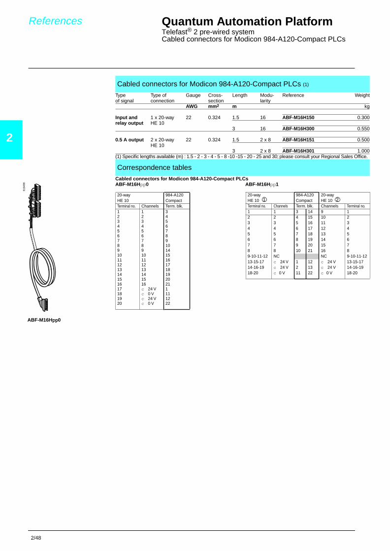
Quantum Automation Platform Telefast® 2 pre-wired systemCabled connectors for Modicon 984-A120-Compact PLCs
Cabled connectors for Modicon 984-A120-Compact PLCs
Cabled connectors for Modicon 984-A120-Compact PLCs (1)
Type Type of Gauge Cross- Length Modu- Reference Weightof signal connection section larity
AWG mm 2 m kg
Input and 1 x 20-way 22 0.324 1.5 16 ABF-M16H150 0.300relay output HE 10
3 16 ABF-M16H300 0.550
0.5 A output 2 x 20-way 22 0.324 1.5 2 x 8 ABF-M16H151 0.500HE 10
3 2 x 8 ABF-M16H301 1.000(1) Specific lengths available (m) : 1.5 - 2 - 3 - 4 - 5 - 8 -10 -15 - 20 - 25 and 30; please consult your Regional Sales Office.
Correspondence tables
ABF-M16Hpppppppp0
8164
98 ABF-M16Hpp0 ABF-M16Hpp1
References
20-way 984-A120HE 10 CompactTerminal no. Channels Term. blk.1 1 32 2 43 3 54 4 65 5 76 6 87 7 98 8 109 9 1410 10 1511 11 1612 12 1713 13 1814 14 1915 15 2016 16 2117 c 24 V 118 c 0 V 1119 c 24 V 1220 c 0 V 22
2/49
2
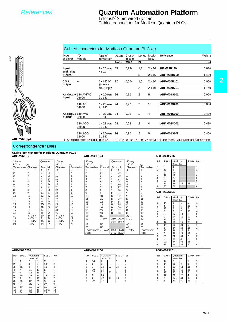
References Quantum Automation Platform Telefast® 2 pre-wired systemCabled connectors for Modicon Quantum PLCs
Cabled connectors for Modicon Quantum PLCs (1)
Type I/O Type of Gauge Cross- Length Modu- Reference Weightof signal module connection section larity
AWG mm 2 m kg
Inputand relay output
– 2 x 20-wayHE 10
22 0,324 1,5 2 x 16 BF-M32H150 0,650
3 2 x 16 ABF-M32H300 1,150
0.5 Aoutput
– 2 x HE 1020-way+ ext. supply
22 0,324 1,5 2 x 16 ABF-M32H151 0,650
3 2 x 16 ABF-M32H301 1,150
Analogueinput
140 AVI/ACI 1 x 25-way 24 0,22 2 8 ABF-M08S201 0,60003000 SUB-D
140 ACI 04000
2 x 25-waySUB-D
24 0,22 2 16 ABF-M16S201 0,620
Analogueoutput
140 AVO 02000
1 x 25-way 24 0,22 2 4 ABF-M04S200 0,450SUB-D
140 ACO 02000
1 x 25-way 24 0,22 2 4 ABF-M04S201 0,450SUB-D
140 ACO 13000
1 x 25-way 24 0,22 2 8 ABF-M08S202 0,450SUB-D
(1) Specific lengths available (m) : 1.5 - 2 - 3 - 4 - 5 - 8 -10 -15 - 20 - 25 and 30; please consult your Regional Sales Office.
Correspondence tables
Cabled connectors for Modicon Quantum PLCsABF-M32Hpp0 ABF-M32Hpp1 ABF-MO8S202
ABF-M16S201
ABF-M08S201 ABF-M04S200 ABF-M04S201
ABF-M32Hpppppppp1
8165
00
20-way Quantum 20-wayHE 10 HE 10 Terminal no. Channels Term. blk Channels Terminal no.1 1 1 21 17 12 2 2 22 18 23 3 3 23 19 34 4 4 24 20 45 5 5 25 21 56 6 6 26 22 67 7 7 27 23 78 8 8 28 24 89 9 11 31 25 910 10 12 32 26 1011 11 13 33 27 1112 12 14 34 28 1213 13 15 35 29 1314 14 16 36 30 1415 15 17 37 31 1516 16 18 38 32 1617 c 24 V 10 30 c 24 V 1718 c 0 V 9 29 c 0 V 1819 c 24 V 20 40 c 24 V 1920 c 0 V 19 39 c 0 V 20
1 220-way Quantum 20-wayHE 10 HE 10 Terminal no. Channel Term. blk Channels Terminal no.1 1 1 21 17 12 2 2 22 18 23 3 3 23 19 34 4 4 24 20 45 5 5 25 21 56 6 6 26 22 67 7 7 27 23 78 8 8 28 24 89 9 11 31 25 910 10 12 32 26 1011 11 13 33 27 1112 12 14 34 28 1213 13 15 35 29 1314 14 16 36 30 1415 15 17 37 31 1516 16 18 38 32 1617 NC NC 1718 c 0 V 9/19 29/39 c 0 V 18
shunt shunt19 NC NC 1920 NC NC 20Power supply c 24 V 10/20 30/40 c 24 V Power supply cable shunt shunt cable
1 2Pair SUB D Modicon SUB D Pair
Term. blk1 2 4 12 16 8 23 5 14 34 19 18 45 8 24 56 22 28 67 11 34 36 13 78 25 38 8
Pair SUB D Modicon SUB D PairTerm. blk
1 14 2 1 2 12 3 4 3 16 23 17 6 5 5 34 6 8 7 19 45 20 12 11 8 56 9 14 13 22 67 23 16 15 11 78 12 18 17 25 81 14 22 21 2 12 3 24 23 16 23 17 26 25 5 34 6 28 27 19 45 20 32 31 8 56 9 34 33 22 67 23 36 35 11 78 12 38 37 25 8
Pair SUB D Quantum SUB D PairTerm. blk
1 1 1 3 2 12 3 6 2 14 23 15 5 7 16 34 4 11 13 5 45 17 12 16 6 56 18 15 17 19 67 7 21 23 8 78 20 22 26 9 89 21 25 27 22 910 10 31 33 11 1011 23 32 36 12-13 1112 24 35 37 25 12
Pair SUB D Quantum SUB D PairTerm. blk
1 14 2 1 1 15 2 8 52 3 12 11 15 26 16 18 63 17 22 21 4 37 5 28 74 6 32 31 18 48 19 38 8
Pair SUB D Quantum SUB D PairTerm. blk
5 14 2 1 2 51 14 10 9 1 16 3 12 11 16 62 3 20 19 15 27 17 22 21 5 73 17 30 29 4 38 6 32 31 19 84 6 40 39 18 4

2/50
2
Quantum Automation PlatformCableFast cabling System
General
General
The CableFast wiring system eliminates wiring between the I/O module and field wiring terminal blocks. The CableFastsystem reduces wiring time, lowers installation cost, and eliminates wiring errors.
The CableFast system consists of pre-wired Quantum field wiring terminal strips, available in various cable lengths thatare terminated with "D" type connectors. The "D" connectors plug into DIN rail mounted terminal blocks offered in straightthrough or special application versions. Cables and terminal blocks are ordered separately and all terminal blocks maybe used with any cable length. Pigtail cable versions are also available.
i 140 CFA 040 00 The A block is a straight through point to point connection on the terminal block.Wiring of this block is identical to wiring the Quantum I/O connector (140 XTS 002 00).
i 140 CFB 032 00 The B block is used for individually fused 2-wire digital inputs. This terminal block is designedto prevent a single point failure from affecting the remaining inputs. It is not recommended forsourced 1-wire inputs (powered from the field).
i 140 CFC 032 00 The C block provides connection for 32 group fused input or output points. The block may beused for 1- or 2-wire inputs or outputs, and features a fuse per group, four groups total. Usersselect input or output mode via four switches located on the module. (The default is input mode.)
i 140 CFD 032 00 The D block is used for sensors requiring either 2- or 3-wire electrical interface. A fuse per groupis supplied to accomodate the I/O module (4) groups.
i 140 CFE 032 00 The E block provides connection for 32 individually fused 24 Vdc outputs. 1- and 2-wireinterfacing may be selected. Field power must be supplied to the four groups.
i 140 CFG 016 00 The G block is a high power output block used on both AC and DC circuits requiring up to 2 A.Individual fusing is provided and may be used in both 1- and 2-wire installations. It is also usedfor isolated AC modules.
i 140 CFH 008 00 The H block is used for analog inputs, with individual fusing provided per channel. This interfaceprovides plus, minus, shield, and power supply interface for both field and loop powerconfigurations.
i 140 CFI 008 00 The I block is used for analog inputs. This interface provides plus, minus, shield, and powersupply interface for both field and loop power configurations.
i 140 CFJ 004 00 The J block is used for analog outputs, with individual fusing provided per channel. This interfaceprovides plus, minus, shield, and power supply interface for both field and loop powerconfigurations.
i 140 CFK 004 00 The K block is used for analog outputs. This interface provides plus, minus, shield, and powersupply interface for both field and loop power configurations.
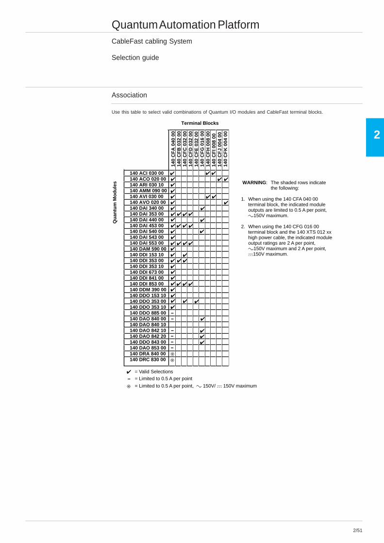
2/51
2
Quantum Automation PlatformCableFast cabling System
Selection guide
Association
Use this table to select valid combinations of Quantum I/O modules and CableFast terminal blocks.
Terminal Blocks
140 ACI 030 00140 ACO 020 00140 ARI 030 10140 AMM 090 00140 AVI 030 00140 AVO 020 00140 DAI 340 00140 DAI 353 00140 DAI 440 00140 DAI 453 00140 DAI 540 00140 DAI 543 00140 DAI 553 00140 DAM 590 00140 DDI 153 10140 DDI 353 00140 DDI 353 10140 DDI 673 00140 DDI 841 00140 DDI 853 00140 DDM 390 00140 DDO 153 10140 DDO 353 00140 DDO 353 10140 DDO 885 00140 DAO 840 00140 DAO 840 10140 DAO 842 10140 DAO 842 20140 DDO 843 00140 DAO 853 00140 DRA 840 00140 DRC 830 00
140
CF
A 0
40 0
014
0 C
FB
032
00
140
CF
C 0
32 0
014
0 C
FD
032
00
140
CF
E 0
32 0
014
0 C
FG
016
00
140
CF
H 0
08 0
014
0 C
FI 0
08 0
014
0 C
FJ
004
0014
0 C
FK
004
00
Qu
antu
m M
od
ule
s
00
0000
0
= Valid Selections= Limited to 0.5 A per point
= Limited to 0.5 A per point, c 150V/ a 150V maximum
WARNING: The shaded rows indicatethe following:
1. When using the 140 CFA 040 00terminal block, the indicated moduleoutputs are limited to 0.5 A per point,c150V maximum.
2. When using the 140 CFG 016 00terminal block and the 140 XTS 012 xxhigh power cable, the indicated moduleoutput ratings are 2 A per point,c150V maximum and 2 A per point,a150V maximum.

2/52
2
Quantum Automation PlatformCableFast cabling System
Specifications
Specifications
Power ratings 150 Vac/Vdc @ 0.5 A per point150 Vac/Vdc @ 2.0 A per point
*Requires the 140 CFG 016 00 terminal block and the 140 XTS 012 XX cable
Dielectric withstanding voltage c1060 V and a1500 V
Creepage and clearance per IEC 1131, UL 508, CSA 22.2 #142-1987
Terminal block wire One wire - #12 AWG (2.5 mm2)Sizes per terminal Two wires - #16 AWG (1.0 mm2) and above
(See below for the maximum number of wires allowed per terminal.)
Note: It is recommended that no more than two wires be used at one time.
Wire Size Number of Wires#24 4#22 4#18 3#16 2#14 1#12 1
Terminal screwsize M3Screwdriver head size 0.13" (3.3 mm) flat head mintype captivefinish tin plate (197 µin min)tightening torque 7.2 lb-in (0.8 Nm)
System flammability rating 94 V-2
Temperatureoperating 0 ... 60 ºC (32 ... 140 ºF)storage -40 ... +65 ºC (-40 ... +149 ºF)
Humidity 0 ... 95% RH noncondensing
Altitude 6,666 ft (2000 m) full operation
Shock +/- 15 g peak, 11 ms, half sine wave
Vibration 10 ... 57 Hz @ 0.075 mm displacement57 ... 150 Hz @ 1 g, total 10 sweeps
Mounting configuration DIN rail mount, NS35/7.5 and NS32
Standard powercable diameter 0.43 in nominal (10.9 mm)
8-#20 AWG (0.8 mm), 7/28 tinned annealed copper; semi rigid PVCnumber of conductors 32-#26 AWG (0.4 mm), 7/34 tinned annealed copper; semi rigid PVCbend radius (I.D.) 0.75 in min (19.0 mm)
High powercable diameter 0.55 in nominal (14.0 mm)number of conductors 8-#18 AWG (1.0 mm), 16/30 tinned annealed copper; semi rigid PVC
32-#20 AWG (0.8 mm), 10/30 tinned annealed copper; semi rigid PVCbend radius (I.D.) 1.50 in min (38.1 mm)
Common specifications
cable jacket jacket color: black, 0.040 in wall min, flexible PVCwire strip length 0.32 in (8 mm)wire marking See the wire color coding tablewire rating 300 V, 105ºC UL rated 2517, CSA Type AWM 1/2 FT 1cable rating 300 V, 105 ºC ratedshielding Aluminum/polyester tape (aluminum side out) attached at connector body (360º)
#22 AWG, 7/30 drain wireShield resistance 16.55 Ohms/Mft nominal
agency approval UL-758; AWM style 2517 VW-1 and CSA C22:210.2; AWM I/II A/B FT1
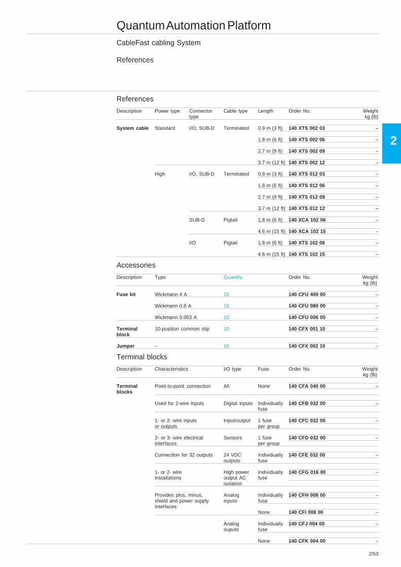
2/53
2
Quantum Automation PlatformCableFast cabling System
References
References
Description Power type Connector Cable type Length Order No. Weighttype kg (lb)
System cable Standard I/O, SUB-D Terminated 0.9 m (3 ft) 140 XTS 002 03 –
1.8 m (6 ft) 140 XTS 002 06 –
2.7 m (9 ft) 140 XTS 002 09 –
3.7 m (12 ft) 140 XTS 002 12 –
High I/O, SUB-D Terminated 0.9 m (3 ft) 140 XTS 012 03 –
1.8 m (6 ft) 140 XTS 012 06 –
2.7 m (9 ft) 140 XTS 012 09 –
3.7 m (12 ft) 140 XTS 012 12 –
SUB-D Pigtail 1.8 m (6 ft) 140 XCA 102 06 –
4.6 m (15 ft) 140 XCA 102 15 –
I/O Pigtail 1.8 m (6 ft) 140 XTS 102 06 –
4.6 m (15 ft) 140 XTS 102 15 –
Accessories
Description Type Quantity Order No. Weightkg (lb)
Fuse kit Wickmann 4 A 10 140 CFU 400 00 –
Wickmann 0.8 A 10 140 CFU 080 00 –
Wickmann 0.063 A 10 140 CFU 006 00 –
Terminal 10-position common stip 10 140 CFX 001 10 –block
Jumper – 10 140 CFX 002 10 –
Terminal blocks
Description Characteristics I/O type Fuse Order No. Weightkg (lb)
Terminal Point-to-point connection All None 140 CFA 040 00 –blocks
Used for 2-wire inputs Digital inputs Individually 140 CFB 032 00 –fuse
1- or 2- wire inputs Input/output 1 fuse 140 CFC 032 00 –or outputs per group
2- or 3- wire electrical Sensors 1 fuse 140 CFD 032 00 –interfaces per group
Connection for 32 outputs 24 VDC Individually 140 CFE 032 00 –outputs fuse
1- or 2- wire High power Individually 140 CFG 016 00 –installations output AC fuse
isolation
Provides plus, minus, Analog Individually 140 CFH 008 00 –shield and power supply inputs fuseinterfaces
None 140 CFI 008 00 –
Analog Individually 140 CFJ 004 00 –ouputs fuse
None 140 CFK 004 00 –