(2) Aircraft Attitude Controlx
65
-
Upload
marcus-drago -
Category
Documents
-
view
17 -
download
6
Transcript of (2) Aircraft Attitude Controlx

AVIONICS
• AVIONICS IS THE BRANCH OF ENGINEERING WHICH DEALS WITH ELECTRONICS IN AIRCRAFT.
• IN AIRCRAFT, ELECTRONICS IS EXTENSIVELY USED FOR AUTOMATION, CONTROL AND SAFETY.

AVIONICS
• AVIONICS HAS THREE DIFFERENT SECTIONS. THEY ARE:
– AIRCRAFT INSTRUMENT SYSTEMS– AIRCRAFT ELECTRICAL SYSTEMS AND– AIRCRAFT RADIO COMMUNICATION AND
NAVIGATION SYSTEMS

Aircraft Attitude control

• The attitude of a aircraft is its orientation with respect to a defined frame of reference.
• Attitude dynamics is the modeling of the changing position and orientation of a aircraft, due to external forces acting on the body.
• Attitude control is the purposeful manipulation of controllable external forces (using aircraft actuators) to establish a desired attitude.
• Attitude determination is the utilization of vehicle sensors to ascertain the current aircraft attitude.

• Controlling aircraft attitude requires:– sensors to measure vehicle attitude,– actuators to apply the torques needed to re-
orient the vehicle to a desired attitude, and– algorithms to command the actuators based
on:• sensor measurements of the current
attitude and • specification of a desired attitude.
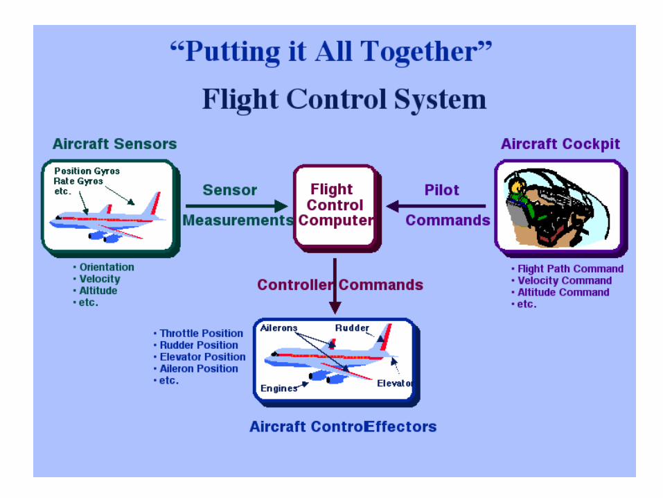

• The integrated field that studies the combination of sensors, actuators and algorithms is called Guidance, Navigation and Control (GNC).

AXES OF AN AIRPLANE• Whenever an airplane changes its flight
attitude or position in flight, it rotates about one or more of three axes, which are imaginary lines that pass through the airplane’s center of gravity.
• The axes of an airplane can be considered as imaginary axles around which the airplane turns, much like the axle around which a wheel rotates.

AXES OF AN AIRPLANE
• The axis, which extends lengthwise through the fuselage from the nose to the tail, is the longitudinal axis.
• The axis, which extends crosswise from wingtip to wingtip, is the lateral axis.
• The axis, which passes vertically through the center of gravity, is the vertical axis.


• the motion about the airplane’s longitudinal axis is called “roll”;
• motion about its lateral axis is referred to as “pitch.”
• an airplane moves about its vertical axis in a motion, which is termed “yaw”—that is, a horizontal (left and right) movement of the airplane’s nose.


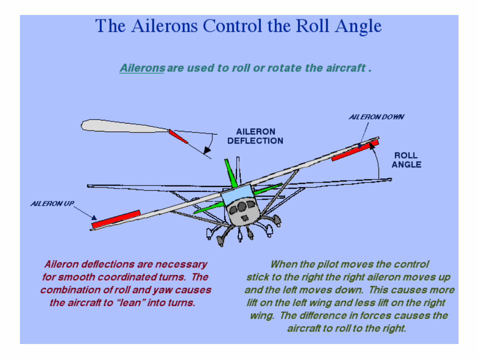


• The three motions of the airplane (roll, pitch, and yaw) are controlled by three control surfaces.–Roll is controlled by the ailerons;–pitch is controlled by the
elevators;– yaw is controlled by the rudder.

Relative attitude sensors• Many sensors generate outputs that reflect the
rate of change in attitude.• these require a known initial attitude, or
external information to use them to determine attitude.
• Many of this class of sensor have some noise, leading to inaccuracies if not corrected by absolute attitude sensors.
Relative attitude sensors
• Gyroscopes• Motion Reference Units

Gyroscopes
• Devices that sense rotation in 3-space, without reliance on observation of external objects.
• a gyroscope consists of a spinning mass, but there are also "Laser Gyros" utilizing coherent light reflected around a closed path.
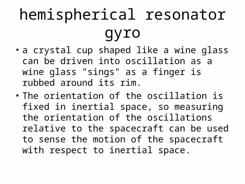
hemispherical resonator gyro
• a crystal cup shaped like a wine glass can be driven into oscillation as a wine glass "sings" as a finger is rubbed around its rim.
• The orientation of the oscillation is fixed in inertial space, so measuring the orientation of the oscillations relative to the spacecraft can be used to sense the motion of the spacecraft with respect to inertial space.

Motion Reference Units
• Motion Reference Units are single or multiaxis motion sensors.
• They utilize Micro-Electro-Mechanical-Structure (MEMS) sensor technology.
• These sensors bring together micro-electronics with micro-machining technology, to make complete systems-on-a-chip with high accuracy.
Absolute attitude sensors
• This class of sensors sense the position or orientation of fields, objects or other phenomena outside the spacecraft.

Horizon sensor Earth Sensor
• An optical instrument that detects light from the 'limb' of the Earth's atmosphere, i.e., at the horizon.
• Thermal Infrared sensing is often used, which senses the comparative warmth of the atmosphere, compared to the much colder cosmic background.
• This sensor provides orientation with respect to the earth about two orthogonal axes.
• It tends to be less precise than sensors based on stellar observation.
Orbital Gyrocompass• Similar to the way that a terrestrial
gyrocompass uses a pendulum to sense local gravity and force its gyro into alignment with earth's spin vector, i.e. point North
• an orbital gyrocompass uses a "horizon sensor" to sense the direction to earth's center, and a gyro to sense rotation about an axis normal to the orbit plane.
• Thus, the horizon sensor provides pitch and roll measurements, and the gyro provides yaw.

Algorithms• Control Algorithms are computer programs that
receive data from vehicle sensors and derive the appropriate commands to the actuators to rotate the aircraft to the desired attitude.
• The algorithms range from very simple to complex nonlinear estimators or many in-between types, depending on mission requirements.
• the attitude control algorithms are part of the software running on the hardware which receives commands from the ground and formats vehicle data Telemetry for transmission to a ground station.

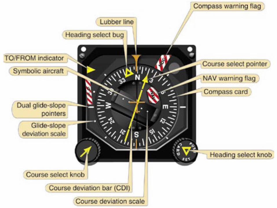
Attitude indicator• An attitude indicator (ADI), also known as
gyro horizon or artificial horizon, is an instrument used in an aircraft to inform the pilot of the orientation of the aircraft relative to earth.
• It indicates pitch (fore and aft tilt), bank or roll (side to side tilt) and yaw (left to right, right to left), and is a primary instrument for flight in instrument meteorological conditions.

Attitude indicators
• Attitude indicators also have significant application under visual flight rules, though some light aircraft do not have them installed.
• Attitude indicators use a gyroscope to establish an inertial platform.
• The gyroscope is geared to a display that has two dimensions of freedom, simultaneously displaying pitch and bank.

• The display may be colored to indicate the horizon as the division between the two colored segments (typically blue for sky and brown for ground), and is intended to be intuitive to use.
• The actual bank angle is calibrated around the circumference of the instrument.
• The pitch angle is indicated by a series of calibration lines, each representing 5° or 10° of pitch.

• The pitch angle is relative to the ground, which is not as helpful as knowing the angle of attack of the wing, a much more critical measure of performance.
• The pilot must infer the total performance by using other instruments such as the airspeed indicator, altimeter, vertical speed indicator, and power instruments, e.g. an engine tachometer.

inertiaInertia is the resistance to a change in
momentum (either angular or linear).The gyroscope and the accelerometer are
essential to the control and guidance of an aircraft.
For example in certain aircrafts the rate gyros and accelerometers provide the aircraft motion feedback which enables a manoeuvre command control to be achieved and an unstable aircraft to be stabilised by the flight control system.

Fundamental Properties of a Gyro
INTRODUCTIONGyroscopes and accelerometers are known as
inertial sensors.This is because they exploit the property of
inertia to sense motion. changes in angular motion in the case of the
gyro.changes in linear motion in the case of the
accelerometer.

inertiaInertia is the resistance to a change in
momentum (either angular or linear).The gyroscope and the accelerometer are
essential to the control and guidance of an aircraft.
For example in certain aircrafts the rate gyros and accelerometers provide the aircraft motion feedback which enables a manoeuvre command control to be achieved and an unstable aircraft to be stabilised by the flight control system.
Gyros and accelerometers are also the essential elements of the spatial reference system or altitude/heading reference system (AHRS) and the inertial navigation system (INS).

Function of The AHRS
The AHRS provides the vertical and directional reference information for the pilot’s head up display (HUD), electronic flight instrument system (EFIS), the autopilot system and the navigation system.

Function of the INSThe INS provides a completely self contained
source of navigation information together with very accurate altitude and heading information.
A Strap down INS and also a strap-down AHRS can provide roll rate, pitch rate, yaw rate and normal and lateral acceleration (and forward acceleration if requires) for the flight control system (FCS).


principle of the spinning rotor gyro
It uses the property of the spin axis of a gimbal suspended spinning flywheel to maintain a fixed direction in space.
The spinning rotor gyroscope uses the fundamental characteristic of the angular momentum of the rotor to resist changing its direction to either provide a spatial reference or to measure the rate of angular rotation.

Rigidity, or gyroscopic inertia
• is the property of a gyroscope which causes it to continue to rotate in the same plane.
• in the absence of any external force, the spin axis will continue to point to the same position in space to which it was originally set.
Rigidity
• In order to enhance the rigidity of a gyro it is necessary to:– increase the spin speed– increase the mass of the wheel– concentrate the mass of the wheel about the
circumference

Precession• If an external force is applied at the gyro, the
gyro will move as if the external force had been applied at a point 90 degrees removed from the actual point of application in the direction of rotation of the gyro.

Rule of Precession• gyro will precess in a direction at 90º to the
applied force, measured round the circumference of the rotor in the direction of spin.
• The force applied appears to have moved 90° in the direction of spin.


free gyrothe spinning rotor is supported in such a way
that the spin axis is free to point in any arbitrary direction and provided there are zero torques acting about its axis of freedom it will stay pointing in this fixed direction in space.

rate gyrothe rotor spin axis is constrained to follow the
rotation the gyro experiences about its input axis or axes.
The torque required to constrain the rotor is directly proportional to the input rate which can then be determined by measuring the torque.

The precession torque Suppose the gyro rotor is rotated through a
small angle about the OX axis in time t.The vector change in the angular momentum is
equal to H = H and is in a direction parallel to OY.H = angular momentum of the rotor = JR
J = moment of inertia of rotor about spin axisR = angular velocity of rotor about spin axis.


Working out the rate of change of angular momentum:
Newton’s second law states thatThe force acting on an object is equal to the mass of this object multiplied by the rate of change of the linear velocity
Which means that in the general case the force acting on a certain body is equal to the rate of change of the linear momentum of that body.
dtmvd
dtdvmF )(

dtvmdF
vmmomentumLinear)(&
.)( momentumlinearofchangeofratedtvmd

The torque T is equal to the moment of inertia J around a certain axis multiplied by the rate of change of angular velocity around that axis.Rate of change of angular velocity =
This is the case when the torque axis (torque vector) is in line with the spinning axis.
or
dtdor
dtd
J
dtdJTor

torqueWhen the torque T is applied to change the direction of angular momentum, the torque applied is not in line with the angular momentum i.e. the spinning axis.This case is different, and Newton’s second law states that:The applied torque is equal to the rate of change of the angular momentum.

In this case the direction of the angular momentum H is changing. Thus H is not in the direction of H.where H = J R
Therefore
tmomentumangularinchangeTheTorque
tH
tH
tHT

On the limit when t 0 Then
This is called gyroscopic reaction torque.and
Notice that the direction of is the same as the direction of the torque axis
HdtdHT
HT
HT
This behavior, where the application of a torque about an axis orthogonal to the spin axis causes the rotor to rotate about a third axis which is mutually orthogonal to both the applied torque axis and the spin axis, is called precession.