2 3 4 5 Aliasing Cancellation Condition Aliasing Cancellation Condition : Perfect Reconstruction...
25
Non-Maximal Decimated ilter Bank (NMDFB) an Its Application in eband Signal Processi Dec 6, 2012 Xiaofei Chen
-
Upload
bernice-shelton -
Category
Documents
-
view
225 -
download
2
Transcript of 2 3 4 5 Aliasing Cancellation Condition Aliasing Cancellation Condition : Perfect Reconstruction...

Non-Maximal Decimated Filter Bank (NMDFB) and
Its Application in Wideband Signal Processing
Dec 6, 2012
Xiaofei Chen
2
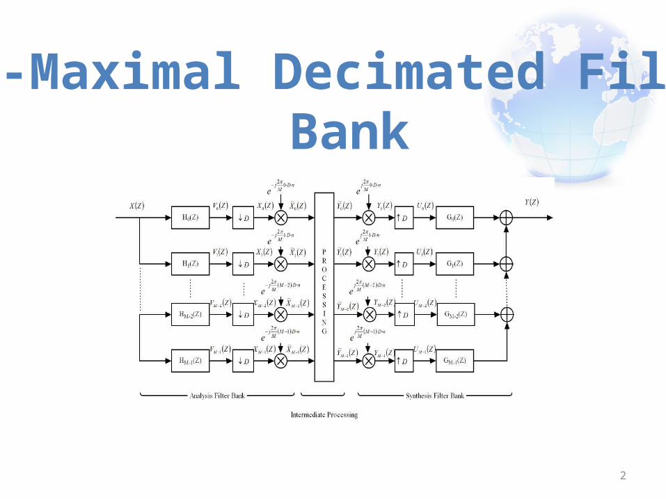
Non-Maximal Decimated Filter Bank

3
Non-Maximal Decimated Filter Bank, Cont’d

4
Non-Maximal Decimated Filter Bank, Cont’d
𝑌 (𝑍 )= 1𝐷𝑮1×𝑀
𝑇 ( 𝒁 )𝕂𝑀 ×𝑀 (𝒁 )ℍ𝑀 ×𝐷 ( 𝒁 ) 𝑿 𝐷×1 ( 𝒁 )= 1𝐷𝑻𝕂
1×𝐷 ( 𝒁 ) 𝑿𝐷× 1 ( 𝒁 )
𝑻𝕂1×𝐷 (𝒁 )≝𝑮1×𝑀
𝑇 (𝒁 )𝕂𝑀×𝑀 ( 𝒁 )ℍ𝑀 ×𝐷 (𝒁 )= [𝑇 𝑠𝕂 (𝑍 )𝑻 𝐴
𝕂 (𝑍 ) ]𝑌 (𝑍 )= 1
𝐷𝑇 𝑠
𝕂 (𝑍 )𝑋 (𝑍 )+ 1𝐷𝑻 𝐴
𝕂 (𝑍 ) 𝑿 (𝑍 )

5
Non-Maximal Decimated Filter Bank, Cont’d
𝐻 (𝑍𝑊 𝐷𝑑 )𝐺 (𝑍 )=0 , ∀𝑑=1 ,…,𝐷−1
∑𝑚=0
𝑀−1
𝐻 (𝑍𝑊𝑀𝑚 )𝐺 (𝑍𝑊𝑀
𝑚 )=𝑍−𝑛𝐷
Aliasing Cancellation Condition:
Perfect Reconstruction Condition:

6
Polyphase Implementation of NMDFB (AFB)
M-path Partition of the mth channel filter:

7
Polyphase Implementation of NMDFB (SFB)
M-path Partition of the mth channel synthesis filter:

8
Filtering with NMDFB
NMDFB filter:
𝑌 𝑓 (𝑍 )=𝑇 𝑠𝕂 (𝑍 ) 𝑋 (𝑍 )+𝑻 𝐴
𝕂 (𝑍 ) 𝑿 (𝑍 )≅𝑇 𝑠𝕂 (𝑍 ) 𝑋 (𝑍 )
Time Domain filter:
𝑌 𝑡 (𝑍 )=𝑆 (𝑍 )𝑍−𝑛𝐷 𝑋 (𝑍 )

9
Filtering with NMDFB, Cont’d
Error between two filtering models:
Error Transfer Function:
ℰ (𝑍 )=𝑌 𝑡 (𝑍 )−𝑌 𝑓 (𝑍 )= [𝑇 𝑠𝕂 (𝑍 )𝑍𝑛𝑑−𝑆 (𝑍 ) ] 𝑋 (𝑍 )𝑍−𝑛𝑑

10
Filtering with NMDFB, Cont’d
Piecewise Constant Approximation:
Linear Interpolation
~h𝑁𝑌𝑄 (𝑛)= 1𝑀𝑆𝐼𝑁𝐶2( 1𝑀 𝑛) , 𝑓𝑜𝑟 −𝑛𝑑≤𝑛≤𝑛𝑑
~𝐻𝑁𝑌𝑄 (𝜔−𝜔𝑚)={1−|𝜔−𝜔𝑚
2𝜋 /𝑀 |,𝜔∈[𝜔𝑚−2𝜋𝑀,𝜔𝑚+ 2𝜋
𝑀]
0 , h𝑂𝑡 𝑒𝑟𝑤𝑖𝑠𝑒

11
Filtering with NMDFB, Cont’d
Piecewise Constant Approximation Performance:
|𝑇 ℰ ,𝑚𝑅𝑒 (𝜔 )|≤ |�̇�𝑅𝑒 (𝜔 )|
𝜔∈ [𝜔𝑚−𝜋𝑀,𝜔𝑚±
𝜋𝑀 ]Max
∙𝜋𝑀
=𝐵ℰ ,𝑚𝑅𝑒
|𝑇 ℰ ,𝑚𝐼𝑚 (𝜔 )|≤ |�̇�𝐼𝑚 (𝜔 )|
𝜔∈ [𝜔𝑚−𝜋𝑀,𝜔𝑚±
𝜋𝑀 ]Max
∙𝜋𝑀
=𝐵ℰ ,𝑚𝐼𝑚
|𝑇 ℰ ,𝑚 (𝜔 )|≤√ (𝐵ℰ ,𝑚𝑅𝑒 )2+(𝐵ℰ ,𝑚
𝐼𝑚 )2≝𝐵ℰ ,𝑚
𝜙𝑚≤𝑎𝑡𝑎𝑛( 𝐵ℰ ,𝑚
√ (𝛾𝑠 ,𝑚 )2− (𝐵ℰ ,𝑚 )2 ) , 𝑓𝑜𝑟 𝛾𝑠 ,𝑚>𝐵ℰ ,𝑚
𝛾𝑠 ,𝑚≝ |𝑆 (𝜔 )|𝜔∈[𝜔𝑚−
𝜋𝑀,𝜔𝑚 ±
𝜋𝑀 ]𝑀𝑖𝑛

12
Filtering with NMDFB, Cont’d
Linear Interpolation Approximation Performance:
|𝑇 ℰ ,𝑚𝑅𝑒 (𝜔 )|≤ |�̈�𝑅𝑒 (𝜔 )|𝜔∈ [𝜔𝑚 ,𝜔𝑚+1]
Max∙12 ( 𝜋𝑀 )
2
=𝐵ℰ ,𝑚𝑅𝑒
|𝑇 ℰ ,𝑚𝐼𝑚 (𝜔 )|≤ |�̈�𝐼𝑚 (𝜔 )|𝜔∈ [𝜔𝑚 ,𝜔𝑚+1]
Max∙12 ( 𝜋𝑀 )
2
=𝐵ℰ ,𝑚𝐼𝑚
|𝑇 ℰ ,𝑚 (𝜔 )|≤√ (𝐵ℰ ,𝑚𝑅𝑒 )2+(𝐵ℰ ,𝑚
𝐼𝑚 )2≝𝐵ℰ ,𝑚
𝜙𝑚≤𝑎𝑡𝑎𝑛( 𝐵ℰ ,𝑚
√ (𝛾𝑠 ,𝑚 )2− (𝐵ℰ ,𝑚 )2 ) , 𝑓𝑜𝑟 𝛾𝑠 ,𝑚>𝐵ℰ ,𝑚
𝛾𝑠 ,𝑚≝ |𝑆 (𝜔 )|𝜔∈ [𝜔𝑚,𝜔𝑚+1 ]𝑀𝑖𝑛

13
NMDFB Design Example
M = 64, D = 32Rectangular
02
M
2
M
4
M
4
M
S ynthe s is F ilte rG (Z)
M o d u la ted Im a g eo f H (Z)
02
M
2
M
4
M
4
M
S ynthe s is F ilte rG (Z )
M o d u la ted Im a g eo f H (Z)
0 4
M
4
M
S ynthe s is F ilte rG (Z )
M o d u la ted Im a g eo f H (Z)
8
M
8
M
M = 64, D = 32Triangular
M = 64, D = 16Triangular
14
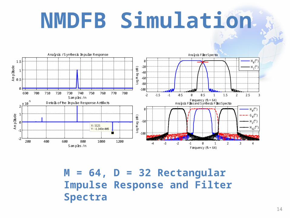
NMDFB Simulation
M = 64, D = 32 RectangularImpulse Response and Filter Spectra
690 700 710 720 730 740 750 760 770 7800
0.5
1
1.5
Analysis / Synthesis Impulse Response
Samples / n
Am
plit
ud
e
200 400 600 800 1000 1200-2
-1
0
1
2x 10
-5
X: 1121Y: -1.343e-005
Details of the Impulse Response Artifacts
Samples / n
Am
plit
ud
e
-2 -1.5 -1 -0.5 0 0.5 1 1.5 2 2.5 3
-100
-80
-60
-40
-20
0
Frequency (fs = 64)
Log
Mag
(dB
)
Analysis Filter Spectra
H
0()
H1()
-4 -3 -2 -1 0 1 2 3 4
-100
-50
0
Frequency (fs = 64)
Log
Mag
(dB
)
Analysis Filter and Synthesis Filter Spectra
H
0()
G0()
H2()
H62
()

15
NMDFB Simulation, Cont’d
M = 64, D = 16 TriangularImpulse Response and Filter Spectra
450 460 470 480 490 500 510 520 530 5400
0.5
1
1.5
Analysis / Synthesis Impulse Response
Samples / n
Am
plit
ud
e
0 200 400 600 800 1000-2
-1
0
1
2x 10
-5
X: 626Y: -4.975e-006
Details of the Impulse Response Artifacts
Samples / n
Am
plit
ud
e
-2 -1.5 -1 -0.5 0 0.5 1 1.5 2 2.5 3
-100
-50
0
Frequency (fs = 64)
Log
Mag
(dB)
Analysis Filter Spectra
H
0()
H1()
-8 -6 -4 -2 0 2 4 6 8
-100
-50
0
Frequency (fs = 64)
Log
Mag
(dB)
Analysis Filter and Synthesis Filter Spectra
H
0()
G0()
H4()
H60
()

16
NMDFB Simulation, Cont’d
M = 64, D = 16 TriangularImpulse Response and Filter Spectra
450 460 470 480 490 500 510 520 530 5400
0.5
1
1.5
Analysis / Synthesis Impulse Response
Samples / n
Am
plit
ud
e
0 200 400 600 800 1000-2
-1
0
1
2x 10
-5
X: 626Y: -4.975e-006
Details of the Impulse Response Artifacts
Samples / n
Am
plit
ud
e
-2 -1.5 -1 -0.5 0 0.5 1 1.5 2 2.5 3
-100
-50
0
Frequency (fs = 64)
Log
Mag
(dB)
Analysis Filter Spectra
H
0()
H1()
-8 -6 -4 -2 0 2 4 6 8
-100
-50
0
Frequency (fs = 64)
Log
Mag
(dB)
Analysis Filter and Synthesis Filter Spectra
H
0()
G0()
H4()
H60
()

17
NMDFB Filtering Simulation 1
M = 64, D = 32 Rectangular / M = 256 Triangular Linear Phase Filtering
0 0.1 0.2 0.3 0.4 0.5
-100
-50
0
Normalized Frequency
Log
Mag
(dB
)
Magnitude Responses of Original Filter and Synthesized Filter
OriSyn
0 0.1 0.2 0.3 0.4 0.5
-100
-50
0
Normalized Frequency
Log
Mag
(dB
)
Magnitude Error between Original Filter and Synthesized Filter
Mag ErrErr Bound
0 0.1 0.2 0.3 0.4 0.5-1
0
1x 10
-4 Phase Error between Original Filter and Synthesized Filter
Normalized Frequency
Nor
mal
ized
Ang
le
Phase ErrErr Bound
0 0.1 0.2 0.3 0.4 0.5
-100
-50
0
Normalized Frequency
Log
Mag
(dB
)
Magnitude Responses of Original Filter and Synthesized Filter
OriSyn
0 0.1 0.2 0.3 0.4 0.5
-100
-50
Normalized Frequency
Log
Mag
(dB
)
Magnitude Error between Original Filter and Synthesized Filter
Mag ErrMinimax BoundSub-Opt Bound
0 0.1 0.2 0.3 0.4 0.5
-101
x 10-5 Phase Error between Original Filter and Synthesized Filter
Normalized Frequency
Nor
mal
ized
Ang
le
Phase ErrorMinimax BoundSub-Opt Bound

18
NMDFB Filtering Simulation 2
M = 64, D = 32 Rectangular / TriangularNon Linear Phase Filtering
-0.5 0 0.5
-20
0
20
Normalized Frequency
Log
Ma
g (
dB
) Magnitude Responses of Original Filter and Synthesized Filter
OriSyn
-0.5 0 0.5
-20
0
20
Normalized Frequency
Log
Ma
g (
dB
) Magnitude Error between Original Filter and Synthesized Filter
Mag ErrErr Bound
-0.5 0 0.5-0.5
0
0.5Phase Error between Original Filter and Synthesized Filter
Normalized Frequency
Norm
alize
d A
ng
le
Phase ErrErr Bound
-0.5 -0.4 -0.3 -0.2 -0.1 0 0.1 0.2 0.3 0.4 0.5
-20
0
20
Normalized Frequency
Log
Mag
(dB)
Magnitude Responses of Original Filter and Synthesized Filter
OriSyn
-0.5 -0.4 -0.3 -0.2 -0.1 0 0.1 0.2 0.3 0.4 0.5
-60
-40
-20
Normalized Frequency
Log
Mag
(dB)
Magnitude Error between Original Filter and Synthesized Filter
Mag ErrMinimax BoundSub-Opt Bound
-0.5 -0.4 -0.3 -0.2 -0.1 0 0.1 0.2 0.3 0.4 0.5
-0.01
0
0.01
Phase Error between Original Filter and Synthesized Filter
Normalized FrequencyNo
rmali
zed
Angl
e
Phase ErrorMinimax BoundSub-Opt Bound

19
NMDFB Filtering Simulation 2
M = 256, D = 64 TriangularNon Linear Phase Filtering
-0.5 -0.4 -0.3 -0.2 -0.1 0 0.1 0.2 0.3 0.4 0.5
-20
0
20
Normalized Frequency
Log
Mag
(dB
)
Magnitude Responses of Original Filter and Synthesized Filter
OriSyn
-0.5 -0.4 -0.3 -0.2 -0.1 0 0.1 0.2 0.3 0.4 0.5-70
-60
-50
-40
Normalized Frequency
Log
Mag
(dB
)
Magnitude Error between Original Filter and Synthesized Filter
Mag ErrMinimax BoundSub-Opt Bound
-0.5 -0.4 -0.3 -0.2 -0.1 0 0.1 0.2 0.3 0.4 0.5
-1
0
1
x 10-3 Phase Error between Original Filter and Synthesized Filter
Normalized Frequency
Nor
mal
ized
Ang
le
Phase ErrorMinimax BoundSub-Opt Bound

20
NMDFB Filtering: Fractional Delay
M = 64, D = 16 TriangularFractional Delay Filtering
-0.5 0 0.5-5
0
5x 10
-3
Normalized Frequency
dB
Mag Res, Dly = 0 SMP
-0.5 0 0.5-5
0
5x 10
-3
Normalized Frequency
dB
Mag Res, Dly = 0.5 SMP
-0.5 0 0.5-5
0
5x 10
-3
Normalized Frequency
dB
Mag Res, Dly = -0.5 SMP
-10 -5 0 5 10
0
0.5
1Impz Dly = 0
SMPs / n
Am
p
ReIm
-10 -5 0 5 10
0
0.5
1Impz Dly = 0.5
SMPs / n
Am
p
ReIm
-10 -5 0 5 10
0
0.5
1Impz Dly = -0.5
SMPs / n
Am
p
ReIm
21
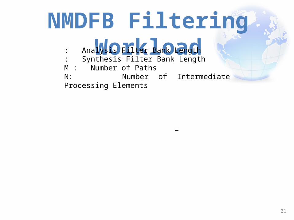
NMDFB Filtering Workload
=
: Analysis Filter Bank Length: Synthesis Filter Bank LengthM : Number of PathsN: Number of Intermediate Processing Elements

22
NMDFB APPLICATIONS
1. Wideband Signal Processing: Effectively reducing the hardware processing rate via NMDFB.
2. Filtering: Linear phase, Non-linear phase, Fractional delay, Masking, Cascade Filtering.
3. Support block timing varying filtering. 4. Support wideband power allocation.

23
Communication Example
Time Domain Timing Recovery & Matched Filtering
NMDFB Domain Timing Recovery & Matched Filtering
256 Real Multiplies per Output
240 Real Multiplies per Output

24
Communication Example
NMDFB Timing Recovery Simulation (Submitted to ICASSP 2013)20 dB SNR / AWGN channel / 0.25 Ts Timing Error
-0.5 -0.4 -0.3 -0.2 -0.1 0 0.1 0.2 0.3 0.4 0.5-60
-40
-20
0
Normalized Freq
Mag /
dB
Spectrums: Time Domain MF, NMDFB MF
TD MF
NMDFB MF
-0.5 0 0.5-120
-100
-80
-60
-40
-20
X: 0.3125Y: -32.22
Normalized Freq
Mag /
dB
Mag Error
simulated err
err bound
-0.5 0 0.5-0.02
-0.01
0
0.01
0.02Phase Error
Normalized Freq
Radiu
s
simulated err
err bound
-2 -1 0 1 2-2
-1
0
1
2
Received Constellation = 0.25Ts
-2 -1 0 1 2-2
-1
0
1
2Timing Recovered Constellation
0 0.5 1 1.5 2
x 104
0
0.1
0.2
0.3
0.4PHASE ACCUMULATOR TIME PROFILE
Sample Index (n)
Tim
ing O
ffset
Phase Acc
Defined Timing Offset
0 0.5 1 1.5 2
x 104
-2
0
2
4
6x 10
-3 Timing Error
Sample Index (n)A
mplit
ude
10x Loop Filter Input
Loop Filter Output

25
Thanks! Open for questions Now!