2 05 S FeedBack Transmission Drive Amplifier Controller ... PID FF Velocity, 5 types Torque ......
32
KOLLMORGEN Servotronix Specialty Electronics Products CD Series 5 2005
Transcript of 2 05 S FeedBack Transmission Drive Amplifier Controller ... PID FF Velocity, 5 types Torque ......

KOLLMORGEN
Servotronix
Specialty Electronics Products
CD Series
5
2005

KOLLMORGEN Ser votronix
3A
6A
10A
SSCD Series 5SSCD Series 520A

KOLLMORGEN Ser votronix
Basic
LoadMotor
FeedBack
TransmissionDriveAmplifierControllerHost
Drive
Amplifier
To Motor, three leads
160 - 300VDC
3/9 Amp
6/18 Amp
10/20 Amp
20/40 AmpFeedback
Halls only
Incremental encoder with Halls
Resolver
Sine
Sine EndDat /
Sine Stegmann 5V
Operation mode
Position, PID FF
Velocity, 5 types
Torque
From Controller
Command Network solution
Analog:
Standard +/-10VDC (C3)
Digital Technology:
RS232/RS485 (C1)
Pulse Following Input (C8)
Sercos (C4)
DeviceNet
CANOpen

KOLLMORGEN Ser votronix
CD ordering information
20 = 20 amp continuous;40 amp peak

KOLLMORGEN Ser votronix
AKM ordering Information

KOLLMORGEN Ser votronix
DEMO CD Series 5
Demo
CE06550
AKM21C
11 units where shipped to NA
Ordering
PRD-DMOCD5EN-00

KOLLMORGEN Ser votronix
Options

KOLLMORGEN Ser votronix
CD Manufacturing Process
Power Board
Control Board
KIT
HiPotAssembly TrnFunctional
Test
ICT TestAltera
MechanicalAssemble
Burn IN FinalTest
ComponentsAssemble
Packing
KITDownloadfirmware
FunctionalTest
ICT TestComponentsAssemble
VAT's
1 hr40 pc's
6-10 min1 pc
PPA

KOLLMORGEN Ser votronix
CD Manufacturing Process
Power StageDigital board Cover
Front panel

KOLLMORGEN Ser votronix
Standard DHR cable Encoder

KOLLMORGEN Ser votronix
Standard DHR Cables Resolver / Sine
KOLLMORGEN Ser votronix
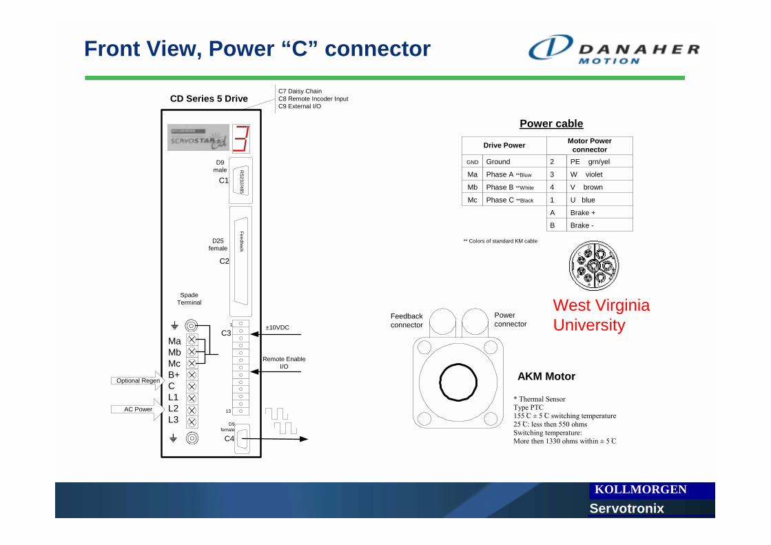
Front View, Power “C” connector
MaMbMcB+CL1L2L3
C1
C4
C2
AC Power
Optional Regen
C3±10VDC
Remote EnableI/O
D25female
D9male
D9female
SpadeTerminal
1
13
C7 Daisy ChainC8 Remote Incoder InputC9 External I/O
CD Series 5 Drive
RS232/485
Feedback
Powerconnector
Feedbackconnector
AKM Motor
* Thermal Sensor Type PTC 155 Cْ ± 5 Cْ switching temperature 25 Cْ: less then 550 ohms Switching temperature: More then 1330 ohms within ± 5 Cْ
Drive Power
Ground
Phase A **Bluw
Phase B **White
Phase C **Black
2
3
4
1
A
B
Motor PowerconnectorPE grn/yel
W violet
V brown
U blue
Brake +
Brake -
GND
Ma
Mb
Mc
Power cable
** Colors of standard KM cable
West Virginia University

KOLLMORGEN Ser votronix
Top view

KOLLMORGEN Ser votronix
Types of Feedbacks

KOLLMORGEN Ser votronix
Encoder Based “C” connector
1
2
3
4
5
66
7
8
9
10
11
12
13
14
15
16
17
18
19
20
21
22
23
24
25
Drive FeedbackC2
A
A\
Shield
B
B\
Shield
5V RTN
H1b
H2b
H3b
Shield
Thermostat High
Shield
Index
Index\
Shield
5V Supply
5V Supply
5V Supply
Shield
H1a Tie to pin 18
H2aTie to pin 18
H3a Tie to pin 18
Thermostat Low
1
2
3
4
7
17
16
15
8
5
6
10
9
Motor feedbackconnectorB green
B\ green/black
A blue
A\ blue/black
GND black
W white
V grey
U brown
*Thermal Sensor
Z violet
Z\ violet/black
Vcc
*Thermal Sensor
C2

KOLLMORGEN Ser votronix
Encoder Based “M” connector
1
2
3
4
5
66
7
8
9
10
11
12
13
14
15
16
17
18
19
20
21
22
23
24
25
Drive FeedbackC2
A
A\
Shield
B
B\
Shield
5V RTN
H1b
H2b
H3b
Shield
Thermostat High
Shield
Index
Index\
Shield
5V Supply
5V Supply
5V Supply
Shield
H1a Tie to pin 18
H2a Tie to pin 18
H3a Tie to pin 18
Thermostat Low
1
2
3
4
7
17
16
15
8
5
6
10
9
Motor feedback connector
B
B\
A
A\
GND
W
V
U
*Thermal Sensor
Z
Z\
Vcc
*Thermal Sensor
green
green/black
blue
blue/black
black
white
grey
brown
white/orange
violet
violet/black
red
orange
Drive Power
Ground
Phase A
Phase B
Phase C
5
3
2
1
A
B
Motor Power connector
Shield
W
V
U
Brake +
Brake -
GND
Ma
Mb
Mc
yellow/green
violet
brown
blue

KOLLMORGEN Ser votronix
Encoder Based Halls Menctype
Hall sensor transition tableRelevant commands:HALLS , MHINVA,B,C, MFBDIRNote- Halls command replay Hc Hb Ha
The correct hall effect commutation is obtained by the followinghall sensor states from "0" position through one electrical cycle.(CW rotation).ZERO 2, IZEROThe ZERO command places the motor in a fixed electricalposition by applying a constant current between phases .ZERO 2 (A-B)
Red marks hall transitionEncoder Charachtaristics
Menctype A/B Marker Pulse Absolute
position comments
0 x x Hall Effects A/B/Z/H
1 x x A/B/Z ENCSTART, ENCINIT
2 X x A/B/Z ENCSTART, ENCINIT
3 x Wake & Shake ENCSTART
4 x Wake & Shake on power up K & ENCSTART
6 x Hall Effects A/B/H
Electrical DegreeCW

KOLLMORGEN Ser votronix
Encoder Based One Rev
One mechanical Rev
PFB = 4 X MENCRES
PRD0 65536
Electrical degree
360 360360 n
Halls
100 001
101 011
010
110
60120
180240
300
MPHASE
MENCOFF
Z index pulse
n= MPOLES / 2 [Number of electrical degree]MENCRES - resolution of the motor encoder [PPR]
[Electrical degree]
[Counts]
[Counts]
[Counts]360
}__{deg
2
4 hIndexIsHigWhereitionHallsTransreeMPOLES
MENCRESMENCOFF ×
×
=
Encoder-Based Alignment issues The AKM motor is offered with two different line count encoders; 1024 and 2048. The published databases assume that the 2048 encoder is chosen. In the event that a 1024 line count encoder is used the Variable MECOFF must be set to ½ of the value defined for a 2048 line count encoder. MECNOFF can be calculated using the following equation:
MENCOFF = MENCRESx4 / (MPOLES/2) x 240/360
1024 2048

KOLLMORGEN Ser votronix
Encoder base Phases
Nomenclature Historically Kollmorgen motor phases have been designated with the letters ‘A’, ‘B’, and ‘C’ for each of the 3 phase connections. The new AKM motors are labeled ‘U’, ‘V’, and ‘W’. The relationship of these signals is shown in the following table:
CD Nomenclature AKM Nomenclature
Phase A Phase W purple Phase B Phase V brawn Phase C Phase U bluw
This translation is important to both the motor lead connections and hall sensor connections as they relate to the commutating encoder versions of the AKM motor series.
Compatible Firmware and Motion Link Revisions CD Series 5 firmware version 7.0.3, or later, should be installed in the drive. Motion Link version 4.5.0 or later should be installed on the computer.A file named AKM.MO3 must be present in the Motion Link directory.
New MOTORTYPE The MOTORTYPE variable in the CD-Series drive was installed to allow translated units for rotary or linear motors. A new MOTORTYPE argument, 3, has been added in firmware version 7.0.3 and supported by Motion Link 4.5.0. Note: for Firm ware up to 7.1.9 you should use MOTORTYPE 0 from Firmware 7.1.10 you can use both MOTORTYPE 0 and 3 will give you MPHASE = 0
West Virginia University

KOLLMORGEN Ser votronix
Resolver Base “C” connector
1
2
3
4
5
66
7
8
9
10
11
12
13
14
15
16
17
18
19
20
21
22
23
24
25
Drive FeedbackC2
Sine High
Sine Low
Shield
Cosine High
Cosine Low
Shield
Shield
Thermostat High
Shield
Ref High Out
Ref Low Out
Shield
Shield
Thermostat Low
3
7
8
4
2
5
9
6
Motor Resolverfeedback connector
COS- blue
COS+ yellow
SIN+ red
SIN - black
*Thermal Sensor
Ref - blk/wht
Ref + red/wht
*Thermal Sensor

KOLLMORGEN Ser votronix
Resolver Base “M” connector
1
2
3
4
5
66
7
8
9
10
11
12
13
14
15
16
17
18
19
20
21
22
23
24
25
Drive FeedbackC2
Sine High
Sine Low
Shield
Cosine High
Cosine Low
Shield
Shield
Thermostat High
Shield
Ref High Out
Ref Low Out
Shield
Shield
Thermostat Low
3
7
8
4
2
5
9
6
Motor Resolverfeedback connector
COS- blue
COS+ yellow
SIN+ red
SIN - black
*Thermal Sensor
Ref - blk/wht
Ref + red/wht
*Thermal Sensor
Drive Power
Ground
Phase A
Phase B
Phase C
5
3
2
1
A
B
Motor Power connector
Shield
W
V
U
Brake +
Brake -
GND
Ma
Mb
Mc
Power cable
yellow/green
violet
brown
blue
West Virginia University

KOLLMORGEN Ser votronix
Resolver Base diagram
SIN- C2 pin 2
SIN+ C2 pin 1
COS- C2 pin 5
COS+ C2 pin 4
C2 Feedback connector
Refer C2 pin 16
Ref High out 18 Vpp@0 8kHz C2 pin 15
DSP
C4 Encoder Equivalent output
RESBWset the cut off Freq of the 2nd order tracking filter300,600,1200Default 600RESBW = Velocity_loop_BW x (4 to 5)
MRESPOLESsets the number of individual poles in the feedback device.Range: 2, 4, 6, 8, 12, 14, 16, …. 60 (resolver-based) 0, 2, 4, 6, 8, 12, 14, 16, …. 60 (encoder-based)Units: poles Default: motor data
Resultion 16 bitAutomatic Calibration at each power up
ENCOUTsets the resolution (number of lines) of the encoder equivalent output channelfor resolver based systems only.one electrical revolution = one mechanical revolution.Type: switch mode (R/W) Range: 512, 1024, 2048, 4096, 8192, or 16384
Digital Board
TempSensor

KOLLMORGEN Ser votronix
Resolver Base
Resolver Requirment and specificationCan use single(two poles) or multi-speed(multiple poles) resolver feedback tomonitor the motor shaftType: Control transmitterTransformation Ratio: approx.0.5±0.1Modulation Frequency: approx. 8 kHzInput voltage (from drive): 6.36 Vac rms (18Vpp @ 0)Max DC Resistance: 120 ohmMax Drive Current: 200mA ac rmsOutput voltage: =Input Voltage * Transformation Ratio, 3 Vac
One mechanical Rev
PFB = 65536xMRESPOLES/2
PRD0 65536
Electrical degree
360 360360 n
Number of electrical degree = MPOLES / 2MPHASE

KOLLMORGEN Ser votronix
Resolver Base
Compatible Firmware and Motion Link RevisionsCD Series 5 firmware version 7.0.3, or later, should be installed in the drive. Motion Link version 4.5.0
or later should be installed on the computer. Resolver-based CD Drives with label 'Version "TYPE B" are recommended for resolver-based (CRxx5xx) applications. A file named AKM.MO3 must be present in the Motion Link directory
Resolver-Based systems settings and offsetsThe resolver alignment position is different in the AKM motors than historically found in Kollmorgen
XT or Goldline motors. Setting MOTORTYPE to 3 automatically compensates for this difference.
If MOTORTYPE is set to 0 then the following recommendations must be followed when using a CRxx5xx drive with the AKM motor:
The CD variable called 'MPHASE' must be set to accommodate this difference. The correct value for MPHASE can be calculated using the following formula:
MPHASE = 300 - 90 * (Number of Pole-Pairs)
The number of pole pairs for the AKM motor is found on its data sheet. Should the resulting calculation be less than 0 (a negative result) keep adding 360 to the result until the answer is positive. Cutting to the bottom line - MPHASE is 30 for 3 pole pair motors, 300 for 4 pole pair motors, 210 for 5 pole pair motors, and 120 for 6 pole pair motors.
Setting MOTORTYPE to 3 automaticly compensate the MPHASE to 0.

KOLLMORGEN Ser votronix
Recommended Motor/ Servo Drive Systems, 240 VAC, 320 VDC bus

KOLLMORGEN Ser votronix
COMP File
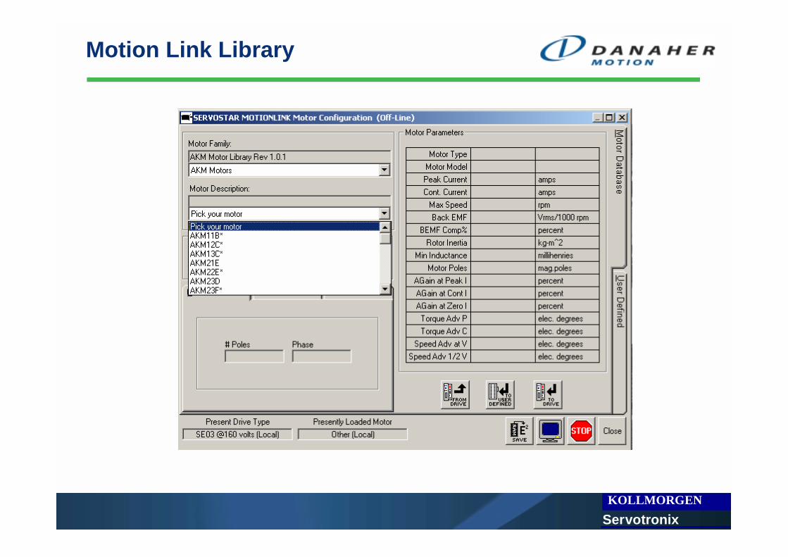
Motion link motor libraryXLS file “AKM CD5 Comp Calculator.xls”Others
KOLLMORGEN Ser votronix
Motion Link Library

KOLLMORGEN Ser votronix
AKM_Motor_Selection_Guide.pdf

KOLLMORGEN Ser votronix
AKM CD5 Comp Calculator.xls
Motor Data Sheet Parameters:Parameter Value Units DescriptionMotor Model Numer: AKM63K Text Enter just the AKM, Frame Size, and Winding Designator
Ics Continuous Rated Current 9.9 Amp rms Enter the Motor's rated continuous current in amperesIp Peak Current 29.7 Amp rms Enter the Motor's rated peak current in amperes
Nrtd Rated Speed at 320 Vdc 1500 RPM Be sure to enter the 230V ac value - not the mechanical limtKe Back EMF 109.9 Volts/1k RPM Enter the motors back emf constant for this winding configurationRm Resistance 1.09 Ohms Enter the resistance of the motor for this winding configurationL Inductance 9.3 mH Enter the inductance of the motor for this winding configuration
Jm Inertia 24.2 kg-cm2 Enter the motor's inertia in the stated unitsW Weight 24.4 Lbs Enter the weight of the motor (Used for adaptive gain calculations)
Pole Pairs 5 Pairs Enter the pole-pair paramter not the number of poles
Drive Data Sheet Parameters:Parameter Value Units DescriptionContinuous rated current 10 Amperes Continuous rated output in Amps RMS/PhasePeak Rated Current 20 Amperes Peak rated output in Amps RMS/PhaseDrive Series 5 Numeric Enter '2' for CD Series 2, CD Lite, or CD SynqNet or '5' for CD Series 5
AKM Motor Series CD Series 5 Compensation Calculator

KOLLMORGEN Ser votronix
AKM CD5 Comp Calculator.xls
Calculated Compensation Parameters
Drive ParametersDIPEAK 200DICONT 100
Motor ParametersMOTORTYPE 3 Version 7.0.0 or higher 1176.147MIPEAK 297MICONT 99MSPEED 1500MBEMF 110 1176.147 Hertz At I PeakMJ 2420MLMIN 930MPOLES 10
Feedback Alignment 20MPHASE (Resolver)* 0MPHASE (Encoder) 0MENCOFF 1092
Adaptive Gains Enter 2 CurrentMLGAINZ 10MLGAINC 9 2400 HertzMLGAINP 7
Torque Angle AdvanceMTANGLC 0MTANGLP 2
Velocity Angle Advance *Note: MPHASE Value for CD Series 5 resolver units requires firmware MVANGLF 30 Version 7.00 or higher. Add 90 electrical degrees for earlier versions.MVANGLH 10
ICONTILIM
Reference Data
AKM63K
Estimated Current Loop Bandwidth
Estimate BW at User Current Level

KOLLMORGEN Ser votronix
Typical configuration
Cheapest configuration
CRxx5x0 and AKMxxx-xxMNR-00
Note: if your motor is with in less then 0.5 m you can order the M connector use it as flying probe and assemble spade terminal for the motor leads and D25 for the feedback
High End configuration
CBxx5x0 and AKMxxx-xxxxDA or DB-00
CNC configuration
CExx5x0 AKMxxx-xxxx1 or 2-00

KOLLMORGEN Ser votronix
Technical Documentations
• AKM_Motor_Selection_Guide.pdf
• SERVOSTARCDSeries5ServoAmplifierCatalog.pdf• CD5AKMEncoderbased.pdf• CD5AKMResolverbased.pdf
• WebX23SEP2005.pdf