ET-2750 User's Guide · 3 Contents ET-2750 User's Guide..... 11
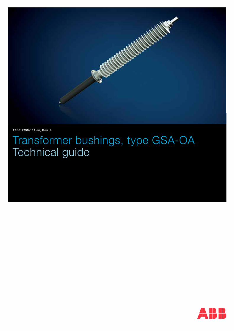
Transformer bushings, type GSA-OATechnical guide
1ZSE 2750-111 en, Rev. 9
Original instruction
The information provided in this document is intended to be general and does not cover all possible applications. Any specific application not covered should be referred directly to ABB, or its authorized representative.
ABB makes no warranty or representation and assumes no liability for the accuracy of the information in this document or for the use of such information. All information in this document is subject to change without notice.
This document must not be copied without our written permission, and the contents thereof must not be imparted to a third party nor be used for any unauthorized purpose. Contravention will be prosecuted.
ContentDesign ............................................................................................................................ 4
Standards ................................................................................................................. 4Features and benefits ................................................................................................ 4Transportation and long term storage ........................................................................ 5General specifications ............................................................................................... 5
Testing ............................................................................................................................ 6Routine testing .......................................................................................................... 6Type tests ................................................................................................................. 6Special tests ............................................................................................................. 6Test tap ..................................................................................................................... 6Test tap adapter ........................................................................................................ 6
Electrical data ................................................................................................................. 7
Dimensions ..................................................................................................................... 8
Connection details .......................................................................................................... 10Outer terminal ........................................................................................................... 10Inner terminal ............................................................................................................ 10Solid rod conductor .................................................................................................. 11Ordering particulars for solid rod conductor .............................................................. 11Conductor insulation ................................................................................................. 11Separate terminal plate with bolts ............................................................................. 12Arcing horns ............................................................................................................. 12
Conductor loading .......................................................................................................... 13Overloading of bushings ........................................................................................... 13Short-time current ..................................................................................................... 13
Ordering particulars ........................................................................................................ 14
Recommendations for positioning................................................................................... 15
4 Technical guide GSA-OA | 1ZSE 2750-111 en, Rev. 9
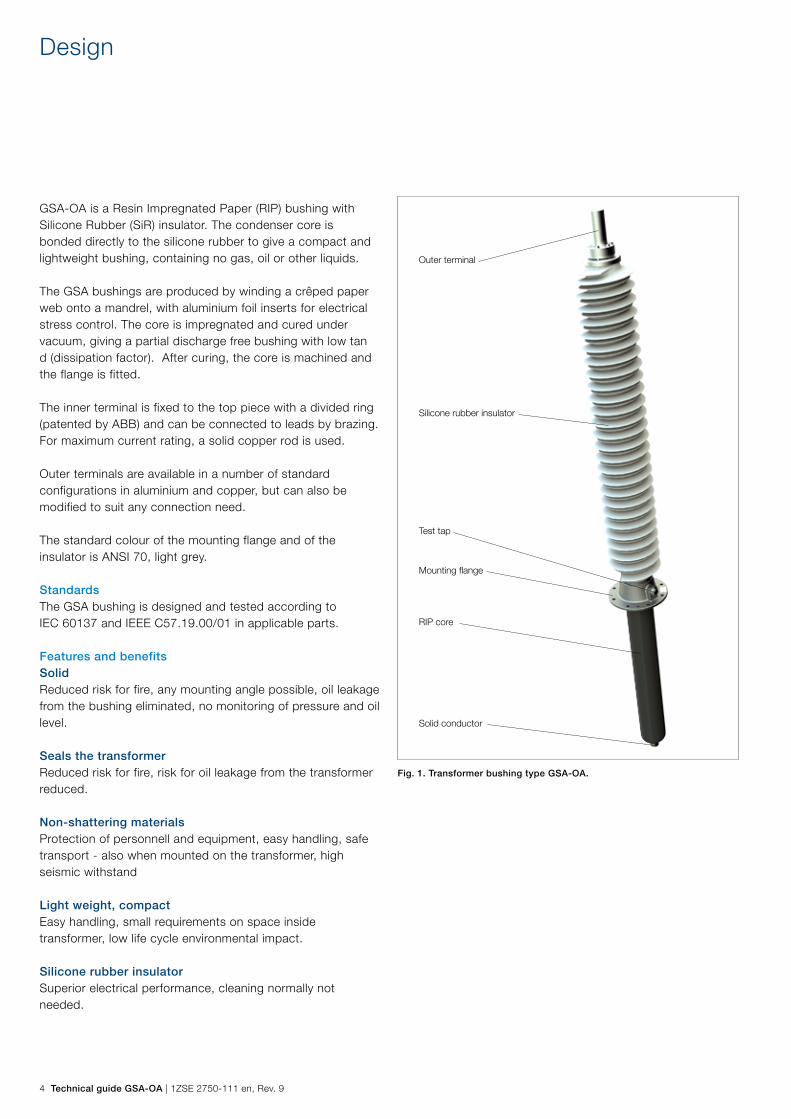
GSA-OA is a Resin Impregnated Paper (RIP) bushing with Silicone Rubber (SiR) insulator. The condenser core is bonded directly to the silicone rubber to give a compact and lightweight bushing, containing no gas, oil or other liquids.
The GSA bushings are produced by winding a crêped paper web onto a mandrel, with aluminium foil inserts for electrical stress control. The core is impregnated and cured under vacuum, giving a partial discharge free bushing with low tan d (dissipation factor). After curing, the core is machined and the flange is fitted.
The inner terminal is fixed to the top piece with a divided ring (patented by ABB) and can be connected to leads by brazing. For maximum current rating, a solid copper rod is used.
Outer terminals are available in a number of standard configurations in aluminium and copper, but can also be modified to suit any connection need.
The standard colour of the mounting flange and of the insulator is ANSI 70, light grey.
StandardsThe GSA bushing is designed and tested according to IEC 60137 and IEEE C57.19.00/01 in applicable parts.
Features and benefitsSolidReduced risk for fire, any mounting angle possible, oil leakage from the bushing eliminated, no monitoring of pressure and oil level.
Seals the transformerReduced risk for fire, risk for oil leakage from the transformer reduced.
Non-shattering materialsProtection of personnell and equipment, easy handling, safe transport - also when mounted on the transformer, high seismic withstand
Light weight, compactEasy handling, small requirements on space inside transformer, low life cycle environmental impact.
Silicone rubber insulatorSuperior electrical performance, cleaning normally not needed.
Design
Fig. 1. Transformer bushing type GSA-OA.
Outer terminal
Silicone rubber insulator
Test tap
Mounting flange
Solid conductor
RIP core
1ZSE 2750-111 en, Rev. 9 | Technical guide GSA-OA 5
Transportation and long term storageThe bushing is surrounded by a sealed moisture-proof wrapping material together with a drying agent upon delivery. The supplied protective wrapping shall not be opened if the bushings are intended to be stored. After transformer test, it is also important to reseal the bushing with the supplied protective wrapping or a similar moisture-proof wrapping, together with a drying agent. The wrapping works as protection for transportation and storage (≤ 6 months). Note that bushings with standard wrapping shall be stored protected from precipitation.
For longer storage times (>6 months) a container have to be ordered separately.
General specificationsFor conditions exceeding the standard specification, please consult the supplier.
Application: Transformers
Classification: Resin impregnated paper, capacitance graded,
outdoor immersed bushing
Ambient temperature: +40 °C to -40 °C, minimum value acc. to
temperature class 3 of IEC 60137
Altitude of site: < 1000 m
Level of rain and
humidity:
1-2 mm rain/min. horizontally and vertically, as
per IEC 60060-1, and 5 mm/min. as per IEEE
Pollution level: According to specific creepage distance and
IEC 60815
Immersion medium: Transformer oil. Maximum daily mean oil
temperature +90 °C. Maximum temporary oil
temperature +115 °C.
Oil level in transformer: Not lower than 25 mm from the bushing flange
Max pressure of
medium:
100 kPa (over pressure)
Angle of mounting: Horizontal to vertical
Test tap: Test tap with 4 mm male contact pin
Capacitance C2 of test
tap:
< 5000 pF
Arcing horns: Optional
Conductor: Solid or flexible draw lead conductor
Markings: Conforming to IEC/IEEE.
6 Technical guide GSA-OA | 1ZSE 2750-111 en, Rev. 9
Routine testingThe bushing is routine tested according to applicable standards. The tests include measurement of partial discharge quantity, tan δ, capacitance, dry power frequency voltage withstand test. The flange is separately tightness tested with helium. A visual inspection is performed.
An individual routine test protocol is delivered with each bushing from ABB.
Type testsComplete type tests have been performed and reports are available on request.
Special testsA number of tests not specified by international standards have also been performed and reports are available on request.
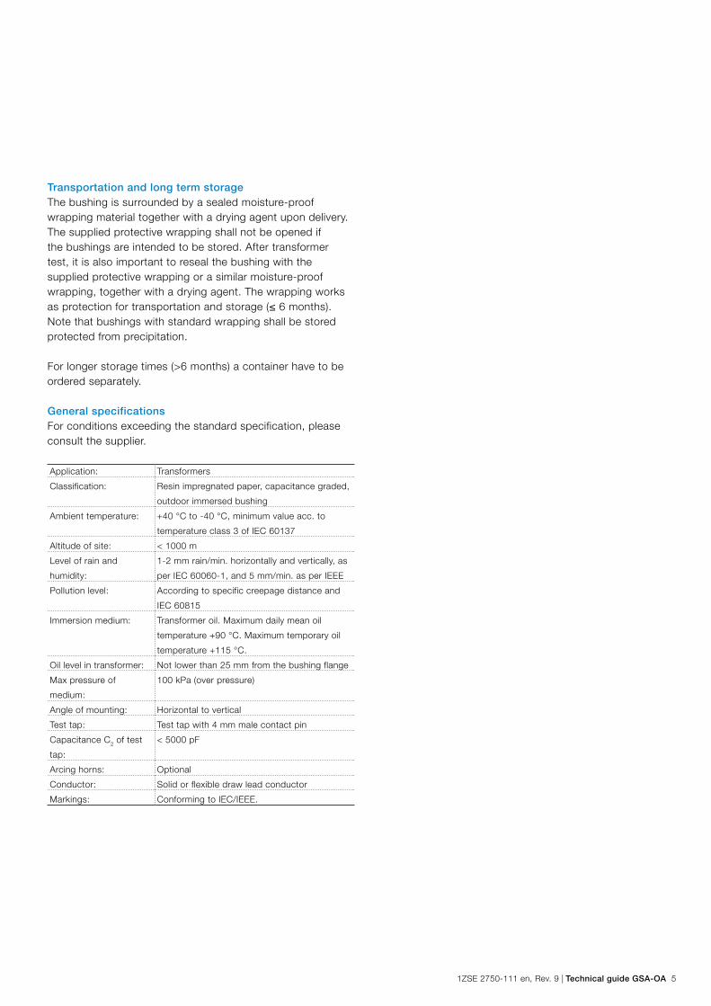
Test tapThe outer conducting layer of the condenser core is connected to an insulated test tap on the flange. During operation the protective cap must be fitted to earth the outer layer to the flange. The maximum test voltage is 2 kV, 50 Hz for 1 minute. The maximum service voltage is 600 V.
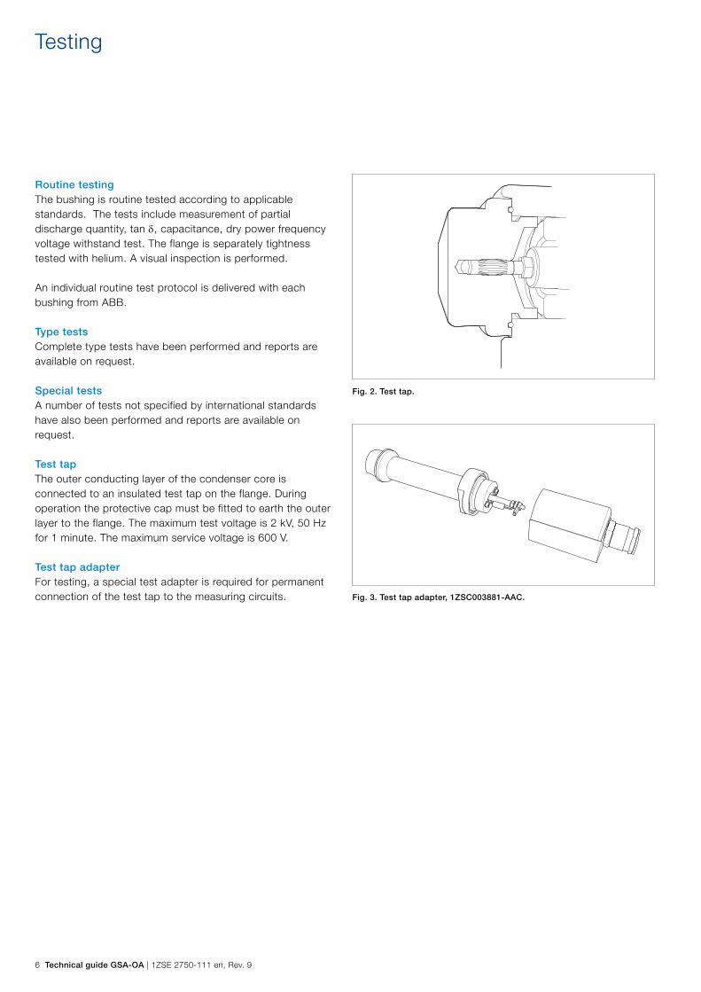
Test tap adapterFor testing, a special test adapter is required for permanent connection of the test tap to the measuring circuits. Fig. 3. Test tap adapter, 1ZSC003881-AAC.
Fig. 2. Test tap.
Testing
1ZSE 2750-111 en, Rev. 9 | Technical guide GSA-OA 7
Electrical data
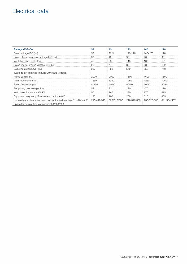
Ratings GSA-OA 52 73 123 145 170
Rated voltage IEC (kV) 52 72.5 123-170 145-170 170
Rated phase-to-ground voltage IEC (kV) 30 42 98 98 98
Insulation class IEEE (kV) 46 69 115 138 161
Rated line-to-ground voltage IEEE (kV) 29 44 88 88 102
Basic Insulation Level (kV)
(Equal to dry lightning impulse withstand voltage.)
250 350 550 650 750
Rated current (A) 2000 2000 1600 1600 1600
Draw lead current (A) 1250 1250 1250 1250 1250
Rated frequency (Hz) 50/60 50/60 50/60 50/60 50/60
Temporary over voltage (kV) 52 73 170 170 170
Wet power frequency AC (kV) 95 140 230 275 325
Dry power frequency. Routine test 1 minute (kV) 120 160 260 310 365
Nominal capacitance between conductor and test tap C1 ±10 % (pF)
Space for current transformer (mm) 0/300/500
215/417/543 325/512/636 216/319/369 233/326/386 311/404/467

8 Technical guide GSA-OA | 1ZSE 2750-111 en, Rev. 9
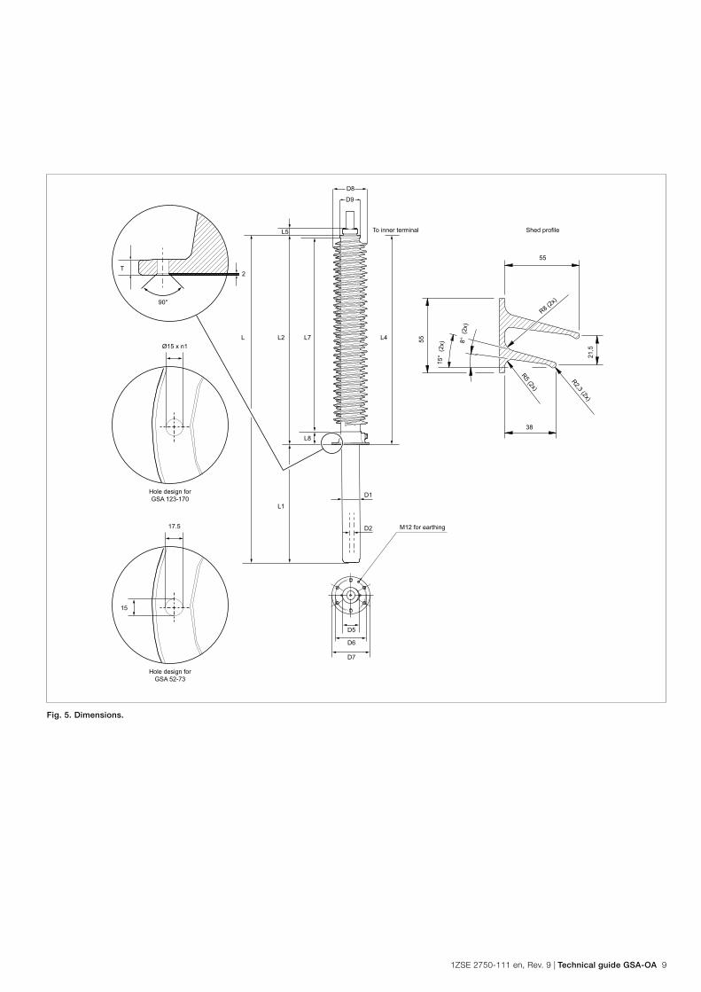
Dimensions are subject to modification without notice.
Dimensions in mm
Type
GSA Cat. No.
Total L Oil
side
L1
Air
side
L2
Draw
lead
L4
Top
part
L5
Arcing
distance
L7
Flange
height
L8
Condenser
core outer
D1
Centre
hole
D2
Min.
gasket
surface
inner
diameter
D5
Hole
circle
D6
Flange
D7
Insulator
sheds
D8
Top
piece
diameter
D9
52 LF 130 052-BA 734 145 589 583 56 467 101 96 51 110 185 225 230 120
-BB 1034 445
-BC 1234 645
73 LF 130 073-BA 1029 260 769 763 56 647 101 96 51 110 185 225 230 120
-BB 1329 560
-BC 1529 760
123 LF 130 123-BA 1444 255 1189 1183 56 1067 101 136 51 150 250 290 270 160
-BB 1744 555
-BC 1944 755
145 LF 130 145-BA 1731 362 1369 1363 56 1247 101 136 51 150 250 290 270 160
-BB 2031 662
-BC 2231 862
170 LF 130 170-BA 2019 410 1609 1603 56 1487 101 136 51 150 250 290 270 160
-BB 2319 710
-BC 2519 910
Space for
current
transformer
(mm)
Cantilever load
Max. permitted loading
perpendicular to the
terminal
Type
GSA
Rated
current (A) Cat. No.
Net
mass
(kg)
Number
of holes
n1
Flange
thickness
T
Creepage distance
total
(mm)
protected
(mm) (N) Test (N)
52 2000 LF 130 052-BA 0 13 6 15 1642 700 2000 1) 4000
-BB 300 16
-BC 500 17
73 2000 LF 130 073-BA 0 18 6 15 2323 1000 2000 1) 4000
-BB 300 20
-BC 500 21
123 1600 LF 130 123-BA 0 45 8 15 3913 1700 2000 2) 4000
-BB 300 50
-BC 500 53
145 1600 LF 130 145-BA 0 52 8 15 4595 2000 2000 2) 4000
-BB 300 57
-BC 500 60
170 1600 LF 130 170-BA 0 61 8 15 5504 2400 2000 2) 4000
-BB 300 66
-BC 500 69
1) Exceeding IEC 60137 Cantilever load Level II.2) Conforming to IEC 60137 Cantilever load Level II.
Dimensions
1ZSE 2750-111 en, Rev. 9 | Technical guide GSA-OA 9
D9
D8
L4L7L2
L5
L8
D5
D6
D7
L1
L
90°
T2
M12 for earthing
Shed profileTo inner terminal
R8 (2x)
55
38
R2,3 (2x)
R5 (2x)
21,5Ø15 x n1
Hole design forGSA 123-170
8° (
2x)
15°
(2x)55
D1
D217.5
15
Hole design forGSA 52-73
Fig. 5. Dimensions.
10 Technical guide GSA-OA | 1ZSE 2750-111 en, Rev. 9
Connection details
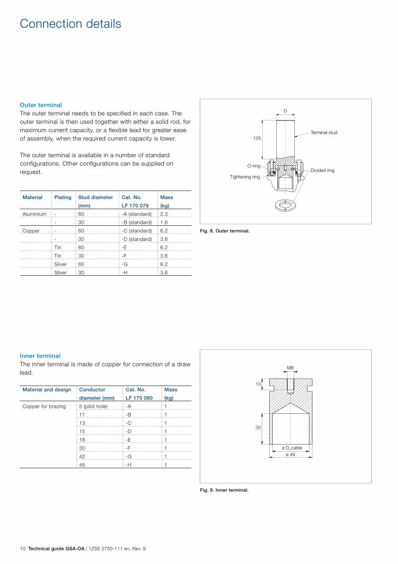
Fig. 8. Outer terminal.
Fig. 9. Inner terminal.
Terminal stud
ø D_cableø 49
M8
13
35
Divided ringO-ring
Tightening ring
125
DOuter terminalThe outer terminal needs to be specified in each case. The outer terminal is then used together with either a solid rod, for maximum current capacity, or a flexible lead for greater ease of assembly, when the required current capacity is lower.
The outer terminal is available in a number of standard configurations. Other configurations can be supplied on request.
Material Plating Stud diameter
(mm)
Cat. No.
LF 170 079
Mass
(kg)
Aluminium - 60 -A (standard) 2.3
- 30 -B (standard) 1.6
Copper - 60 -C (standard) 6.2
- 30 -D (standard) 3.6
Tin 60 -E 6.2
Tin 30 -F 3.6
Silver 60 -G 6.2
Silver 30 -H 3.6
Inner terminalThe inner terminal is made of copper for connection of a draw lead.
Material and design Conductor
diameter (mm)
Cat. No.
LF 170 080
Mass
(kg)
Copper for brazing 5 (pilot hole) -A 1
11 -B 1
13 -C 1
15 -D 1
18 -E 1
30 -F 1
42 -G 1
45 -H 1
1ZSE 2750-111 en, Rev. 9 | Technical guide GSA-OA 11
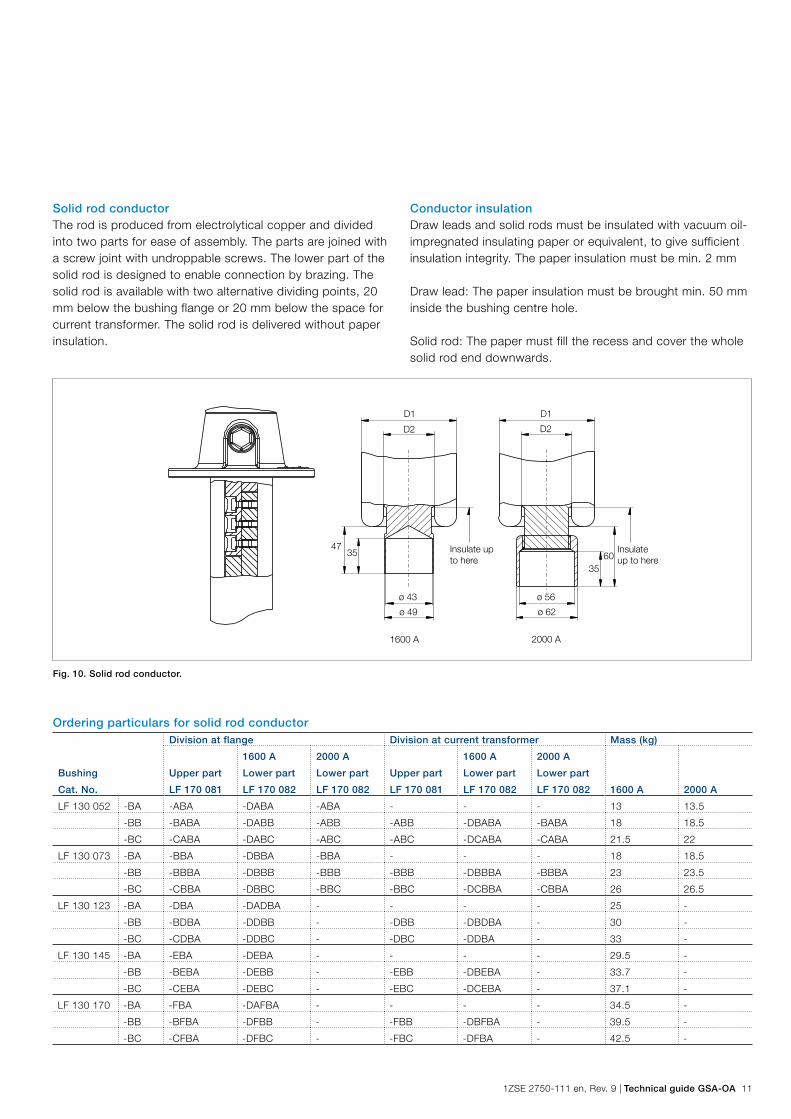
Fig. 10. Solid rod conductor.
D2
D1
D2
D1
3547
6035
ø 49
ø 43 ø 56
ø 62
Insulate up to here
Insulate up to here
1600 A 2000 A
Ordering particulars for solid rod conductor
Bushing
Cat. No.
Division at flange Division at current transformer Mass (kg)
Upper part
LF 170 081
1600 A
Lower part
LF 170 082
2000 A
Lower part
LF 170 082
Upper part
LF 170 081
1600 A
Lower part
LF 170 082
2000 A
Lower part
LF 170 082 1600 A 2000 A
LF 130 052 -BA -ABA -DABA -ABA - - - 13 13.5
-BB -BABA -DABB -ABB -ABB -DBABA -BABA 18 18.5
-BC -CABA -DABC -ABC -ABC -DCABA -CABA 21.5 22
LF 130 073 -BA -BBA -DBBA -BBA - - - 18 18.5
-BB -BBBA -DBBB -BBB -BBB -DBBBA -BBBA 23 23.5
-BC -CBBA -DBBC -BBC -BBC -DCBBA -CBBA 26 26.5
LF 130 123 -BA -DBA -DADBA - - - - 25 -
-BB -BDBA -DDBB - -DBB -DBDBA - 30 -
-BC -CDBA -DDBC - -DBC -DDBA - 33 -
LF 130 145 -BA -EBA -DEBA - - - - 29.5 -
-BB -BEBA -DEBB - -EBB -DBEBA - 33.7 -
-BC -CEBA -DEBC - -EBC -DCEBA - 37.1 -
LF 130 170 -BA -FBA -DAFBA - - - - 34.5 -
-BB -BFBA -DFBB - -FBB -DBFBA - 39.5 -
-BC -CFBA -DFBC - -FBC -DFBA - 42.5 -
Solid rod conductorThe rod is produced from electrolytical copper and divided into two parts for ease of assembly. The parts are joined with a screw joint with undroppable screws. The lower part of the solid rod is designed to enable connection by brazing. The solid rod is available with two alternative dividing points, 20 mm below the bushing flange or 20 mm below the space for current transformer. The solid rod is delivered without paper insulation.
Conductor insulationDraw leads and solid rods must be insulated with vacuum oil-impregnated insulating paper or equivalent, to give sufficient insulation integrity. The paper insulation must be min. 2 mm
Draw lead: The paper insulation must be brought min. 50 mm inside the bushing centre hole.
Solid rod: The paper must fill the recess and cover the whole solid rod end downwards.
12 Technical guide GSA-OA | 1ZSE 2750-111 en, Rev. 9
C
K
H
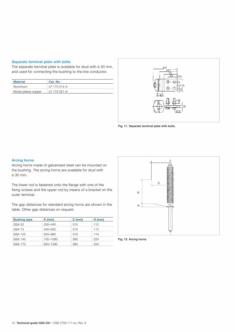
Arcing hornsArcing horns made of galvanised steel can be mounted on the bushing. The arcing horns are available for stud with ø 30 mm.
The lower rod is fastened onto the flange with one of the fixing screws and the upper rod by means of a bracket on the outer terminal.
The gap distances for standard arcing horns are shown in the table. Other gap distances on request.
Bushing type K (mm) C (mm) H (mm)
GSA 52 230–440 315 112
GSA 73 400–620 315 112
GSA 123 620–960 315 114
GSA 145 700–1080 380 224
GSA 170 820–1290 380 224
Separate terminal plate with boltsThe separate terminal plate is available for stud with ø 30 mm, and used for connecting the bushing to the line conductor.
Material Cat. No.
Aluminium LF 170 014-A
Nickel plated copper LF 170 021-A
Fig. 11. Separate terminal plate with bolts.
Fig. 12. Arcing horns.
1ZSE 2750-111 en, Rev. 9 | Technical guide GSA-OA 13
Conductor loading
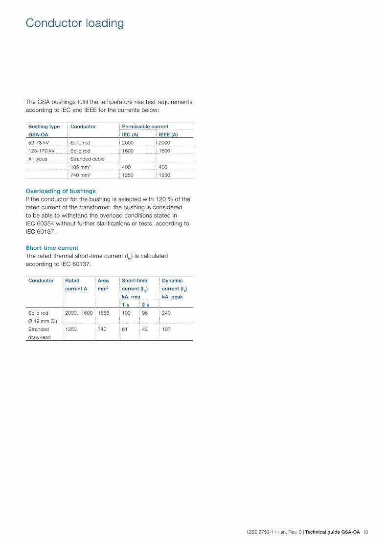
The GSA bushings fulfil the temperature rise test requirements according to IEC and IEEE for the currents below:
Bushing type
GSA-OA
Conductor Permissible current
IEC (A) IEEE (A)
52-73 kV Solid rod 2000 2000
123-170 kV Solid rod 1600 1600
All types Stranded cable
185 mm2 400 400
740 mm2 1250 1250
Overloading of bushingsIf the conductor for the bushing is selected with 120 % of the rated current of the transformer, the bushing is considered to be able to withstand the overload conditions stated in IEC 60354 without further clarifications or tests, according to IEC 60137.
Short-time currentThe rated thermal short-time current (Ith) is calculated according to IEC 60137.
Conductor Rated
current A
Area
mm2
Short-time
current (Ith)
kA, rms
Dynamic
current (Id)
kA, peak
1 s 2 s
Solid rod
Ø 49 mm Cu
2000.. 1600 1886 100 96 240
Stranded
draw-lead
1250 740 61 43 107

14 Technical guide GSA-OA | 1ZSE 2750-111 en, Rev. 9
No.Ur/Uy 52/46 kV Ir 2000 A 50/60 HzLI / SI / AC 250 / - / 120 kVM 16 kg L 445 mm 0-90 °
C1 pF Tan δ %C2 pF Tan δ %
ABB Ludvika, SwedenLF 130 052-BBGSA52-OA/2000/0.3
Fig. 13. Nameplate with marking example.
Ordering particulars
When ordering, please state:
– Type and catalogue number for bushing. – Catalogue number for inner terminal or conductor, lower
and upper part. – Catalogue number for outer terminal. – Additional accessories or modifications. – Test required, in addition to the normal routine tests.
1ZSE 2750-111 en, Rev. 9 | Technical guide GSA-OA 15
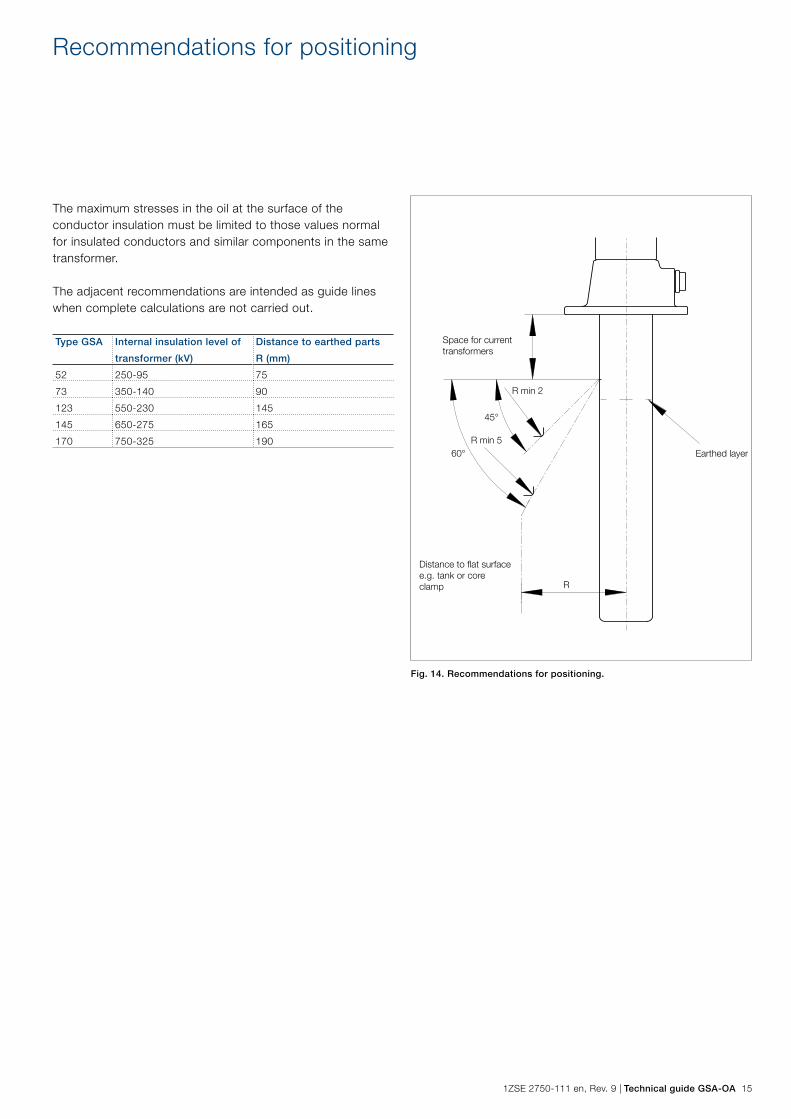
Fig. 14. Recommendations for positioning.
Recommendations for positioning
The maximum stresses in the oil at the surface of the conductor insulation must be limited to those values normal for insulated conductors and similar components in the same transformer.
The adjacent recommendations are intended as guide lines when complete calculations are not carried out.
Type GSA Internal insulation level of
transformer (kV)
Distance to earthed parts
R (mm)
52 250-95 75
73 350-140 90
123 550-230 145
145 650-275 165
170 750-325 190
R min 2
60°
Distance to flat surface e.g. tank or core clamp
Space for current transformers
45°
R min 5
R
Earthed layer
Contact us
© C
opyr
ight
201
7 A
BB
, A
ll rig
hts
rese
rved
.
1ZS
E 2
750-
111
en,
Rev
. 9a
, 20
17-0
6-15ABB AB
ComponentsSE-771 80 Ludvika, Sweden Phone: +46 240 78 20 00 Fax: +46 240 121 57 E-Mail: [email protected] www.abb.com/electricalcomponents