1Th LoarerGas balance and fuel retention – IAEA Chengdu – 18 October 2006 TEC Euratom Th Loarer...
20
1 Th Loarer Gas balance and fuel retention – IAEA Chengdu – 18 October 2006 TEC Eurato m Th Loarer with contributions from C. Brosset 1 , J. Bucalossi 1 , P Coad 2 , G Esser 3 , J. Hogan 4 , J Likonen 5 , M Mayer 6 , Ph Morgan 2 , V Philipps 3 , V. Rohde 6 , J Roth 6 , M Rubel 7 , E Tsitrone 1 , A Widdowson 2 , EU TF on PWI and JET EFDA contributors Gas balance and fuel retention in Fusion Devices 1) Association EURATOM-CEA, CEA-Cadarache,13108 St Paul lez Durance, France. 2) Culham Science Centre, EURATOM-UKAEA Fusion Association, OX14 3DB, UK 3) Institute of Plasma Physics, Association EURATOM-FZJ, 52425 Jülich, Germany 4) Oak Ridge National Laboratory, Fusion Energy Division, TN37831-8072, USA 5) Association EURATOM-TEKES, VTT Processes, PO Box 1608, 02044 VTT Espoo, Finland. 6) Max-Planck IPP-EURATOM Association, Garching, Germany 7) Alfven Laboratory, Royal Institute of Technology, Association EURATOM- VR, Stockholm, Sweeden Outline : Gas balance and fuel retention During a pulse, after/between pulses Integrated over a day, a week and a full campaign Fuel retention mechanisms Summary
-
Upload
darrell-daniel -
Category
Documents
-
view
215 -
download
0
Transcript of 1Th LoarerGas balance and fuel retention – IAEA Chengdu – 18 October 2006 TEC Euratom Th Loarer...

1Th Loarer Gas balance and fuel retention – IAEA Chengdu – 18 October 2006
TECEuratom
Th Loarerwith contributions from
C. Brosset1, J. Bucalossi1, P Coad2, G Esser3, J. Hogan4, J Likonen5, M Mayer6, Ph Morgan2, V Philipps3, V. Rohde6, J Roth6, M Rubel7, E
Tsitrone1 , A Widdowson2, EU TF on PWI and JET EFDA contributors
Gas balance and fuel retention in Fusion Devices
1) Association EURATOM-CEA, CEA-Cadarache,13108 St Paul lez Durance, France.2) Culham Science Centre, EURATOM-UKAEA Fusion Association, OX14 3DB, UK3) Institute of Plasma Physics, Association EURATOM-FZJ, 52425 Jülich, Germany4) Oak Ridge National Laboratory, Fusion Energy Division, TN37831-8072, USA5) Association EURATOM-TEKES, VTT Processes, PO Box 1608, 02044 VTT Espoo, Finland.6) Max-Planck IPP-EURATOM Association, Garching, Germany7) Alfven Laboratory, Royal Institute of Technology, Association EURATOM-VR, Stockholm, Sweeden
Outline:Gas balance and fuel retention
During a pulse, after/between pulses Integrated over a day, a week and a full campaign Fuel retention mechanisms
Summary

2Th Loarer Gas balance and fuel retention – IAEA Chengdu – 18 October 2006
TECEuratom
- Evaluation of the hydrogenic retention in present tokamaks is of crucial importance for
the long discharges foreseen in ITER (400 sec ~ 7min). A retention of 5% of the T
injected would lead to the limit of 350g (working guideline for initial operation) in 70 pulses.
INTRODUCTION
Results from different tokamaks
Limiter machine Divertor machineTEXTOR Tore Supra
Full carbon Full Carbon Actively cooled
Long discharges
ASDEX Upgrade JET
First wall: W High performances Divertor: C Carbon, Berylium
- In the frame of the EU TF on PWI, efforts are underway to investigate the gas
balance and fuel retention during discharges and integrated over experimental
campaign. The aim is to assess the dominant processes of the fuel retention and to
extrapolate to ITER.

3Th Loarer Gas balance and fuel retention – IAEA Chengdu – 18 October 2006
TECEuratom
Retention during pulse
Significant retention unless :• Low fuelling rate (Long L mode in JET)
• No influence of W observed between 2003 and 2005
in AUG (45 to 80% of W coverage)• No influence of ELMs observed so far (W and/or C)
Phase 2 : ~ constant retention rate Always a significant fraction of the injected flux (20-50%), but small fraction of the recycling flux (1-5%)
Phase 2
Low fuelling
AUG
Common features on all devices :
Phase 1 : decreasing retention rate~ 1 to 50 sMachine (Limiter/Divertor), Scenario Conditioning and Material (Be - C – W)…
5
4
3
2
1
0
102
0 Ds-1
4003002001000
Time (s)
# 32299 # 32300
Phase 1
TS

4Th Loarer Gas balance and fuel retention – IAEA Chengdu – 18 October 2006
TECEuratom
Recovery after/between pulses
• Small fraction recovered after shot, but > plasma content (C, C-W and Be)
• Independent of inventory cumulated during the pulse (TS, JET, AUG)Except for disruptions, this amount is independent of Ip, BT, density, input power, fuelling method.
[V. Mertens et al., EPS 2003] AUG
30
25
20
15
10
5
0
Tot
al D
rec
over
ed a
fter
pul
se (
1021
)
5004003002001000
Total D injected during pulse (1021
)
JET, Twall=200°CMKII_SRP DivertorMKII_HD Divertor
JET
wall
RetentionShort pulse ~ 10-30%Long pulse/Strong injection ~ 50%
t
• Recovery ~ retention in phase 1 Transient mechanism

5Th Loarer Gas balance and fuel retention – IAEA Chengdu – 18 October 2006
TECEuratom
Integrated balance - Day
--- Total Injected--- Total exhausted--- Outgased between pulses
6
5
4
3
2
1
0
Part
icle
s (1
023
)
00:00 02:00 04:00 06:00 08:00 10:00 12:00 14:00
Time (h)
Short pulses
Long discharges
TS
Short discharges•Recovery between pulses is significant•Cumulated inventory can be ~ recovered by conditionning (GDC…): Overall balance ~0
Long discharges•Same recovery between pulses but negligible compared to the overall balance
Significant inventory built up proportional to discharge duration
6Th Loarer Gas balance and fuel retention – IAEA Chengdu – 18 October 2006
TECEuratom
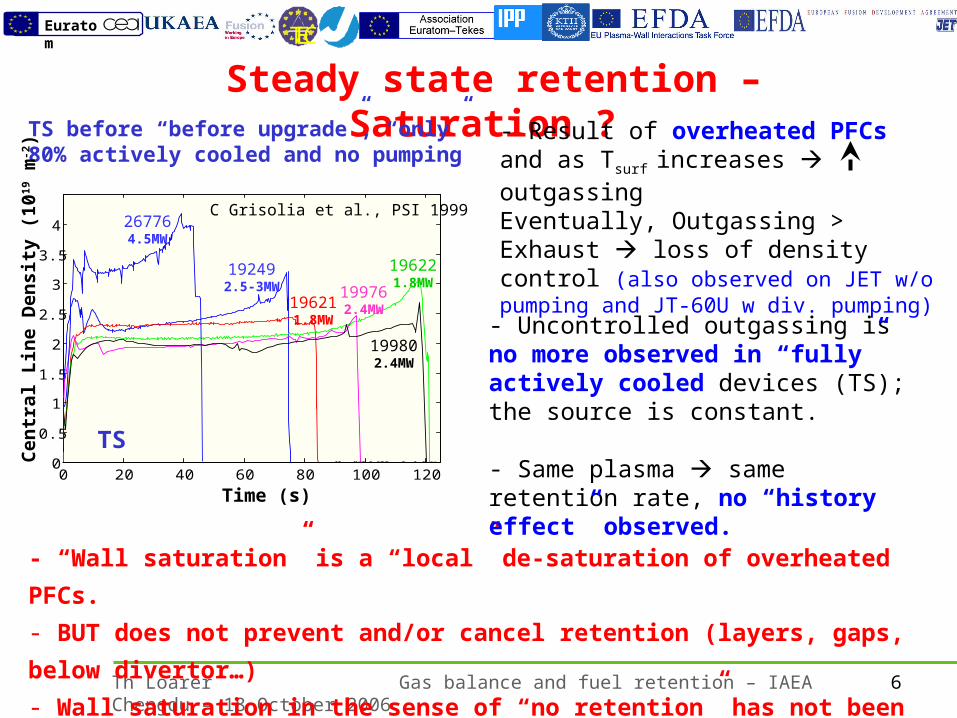
Steady state retention – Saturation ?
- “Wall saturation” is a “local” de-saturation of overheated PFCs.
- BUT does not prevent and/or cancel retention (layers, gaps, below divertor…)
- Wall saturation in the sense of “no retention” has not been observed yet.
TS before “before upgrade”, “only”80% actively cooled and no pumping
0 20 40 60 80 100 1200
0.5
1
1.5
2
2.5
3
3.5
4
Time (s)
Cen
tral
Lin
e D
ensi
ty (
101
9 m
-2)
267764.5MW
192492.5-3MW
196211.8MW
196221.8MW
199802.4MW
199762.4MW
- Result of overheated PFCs and as Tsurf
increases outgassingEventually, Outgassing > Exhaust loss of density control (also observed on JET w/o pumping and JT-60U w div. pumping)
- Uncontrolled outgassing is no more observed in “fully” actively cooled devices (TS); the source is constant. - Same plasma same retention rate, no “history effect” observed.
C Grisolia et al., PSI 1999
TS

7Th Loarer Gas balance and fuel retention – IAEA Chengdu – 18 October 2006
TECEuratom
Integrated gas balance – Day - Week
Accuracy in gas balance studies likely limited by the requirement to substract pairs of large numbers, with inherent accuracy.
For integrated balance of the order of week the accuracy strongly depends on - the “time” for the integration (pulse~10 sec, day~105 sec), - evaluation of the outgassing flux, D and CxHy released (disruptions)
Gas balance is an upper limit of the retention
For integrated gas balance and fuel retention over periods longer than a day or a week, complementary methods are required:Post-mortem analysis of samples from divertor/limiters, main chamber, deposition in gaps in between tiles, below the limiter/divertor…
But this analysis cannot include all PFCs.
Post mortem analysis is a lower limit of the retention

8Th Loarer Gas balance and fuel retention – IAEA Chengdu – 18 October 2006
TECEuratom
D/C
0.12
0.090.05
0.320.310.280.13
1 0.05 0.3 0.38
Fuel retention in JET (MKII GB)
(NRA: D/C ratio, SIMS: layer thicknesses)Only plasma facing surfaces at divertor included (not tile gaps, inner limiters...)
MkIIGB
Divertor time: 57500 sec (16 hours)
D injection: 766g
Inner ion flux: 1.3x1027
C deposition: 400g
Rate: 3.4x10²⁰Cs-1
Inner Divertor: D/C~0.2
Retention of 3% (25g)
J Likonen, P Coad et al.,
- D retention in the divertor: 3% (Mk-IIGB), 2.4% (MKII-SRP).

9Th Loarer Gas balance and fuel retention – IAEA Chengdu – 18 October 2006
TECEuratom
0
2
4
6
8
B + C D measured D assumed
9C456B6A
De
po
sitio
n [1
019 a
t./cm
2]
2002/2003 campaign: Mainly carbon machine (45% W) Retention governed by trapping on inner tile surface (70% inner divertor tiles, 20% in remote ares (below roof baffle,...) Total retention ~4% of input (10-20% from gas balance)
2004/2005 campaign: Full W machine except the divertor (Carbon)
No significant difference in retention between 2002/2003 and 2004/2005
AUG: 2002/2003: Deposition of D and C
M Mayer et al., PSI 2004
10Th Loarer Gas balance and fuel retention – IAEA Chengdu – 18 October 2006
TECEuratom
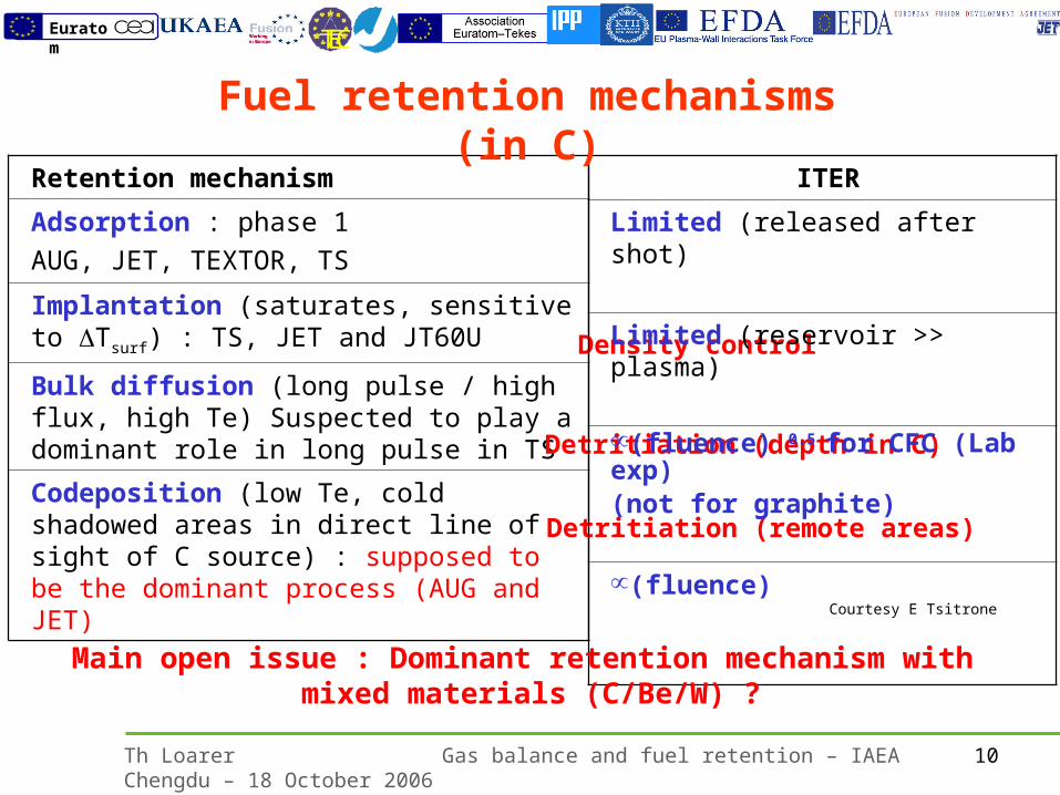
Retention mechanism
Adsorption : phase 1
AUG, JET, TEXTOR, TS
Implantation (saturates, sensitive to Tsurf) : TS, JET and JT60U
Bulk diffusion (long pulse / high flux, high Te) Suspected to play a dominant role in long pulse in TS
Codeposition (low Te, cold shadowed areas in direct line of sight of C source) : supposed to be the dominant process (AUG and JET)
Density control
Detritiation (depth in C)
Detritiation (remote areas)
ITER
Limited (released after shot)
Limited (reservoir >> plasma)
(fluence) 0.5 for CFC (Lab exp)(not for graphite)
(fluence)
Fuel retention mechanisms (in C)
Main open issue : Dominant retention mechanism with mixed materials (C/Be/W) ?
Courtesy E Tsitrone

11Th Loarer Gas balance and fuel retention – IAEA Chengdu – 18 October 2006
TECEuratom
SummaryGas balance and fuel retention: Large data base with carbon showing common features for the retention (AUG, JET, TEXTOR, Tore Supra)- During pulse: significant retention unless low fuelling- Long term: ~0 for short pulse, significant for long discharges (TS)- No “wall saturation” (sense of no retention) is observed for actively cooled devices- Recovery after pulse independent of the cumulated inventory
Retention in carbon dominated devices:10-20% (Gas balance: upper limit) 3-4% (Post-mortem: lower limit)Still no influence of W (AUG: 80%) on the retention (ELMs ? AUG & JET)
Co-deposition dominant process (AUG and JET)
ITER: 200 Pam3s-1, D-T 50% (5 1022Ts-1, 400s), assuming retention similar to carbon devices 5%limit to 70 pulses before reaching 350g detritiation
New results without C as PFC: Full W (AUG) and W-Be (JET) Co-deposition cancelled with full metallic machine and therefore should
significantly reduce the retention

12Th Loarer Gas balance and fuel retention – IAEA Chengdu – 18 October 2006
TECEuratom

13Th Loarer Gas balance and fuel retention – IAEA Chengdu – 18 October 2006
TECEuratom
38 g
73 g
55g
63g
300g 5g
Total inner: 603 g Total outer 380g
Fuel retention in JET (MKII-SRP)
- D retention in the divertor: 2.4% (MKII-SRP), 3% (Mk-IIGB), consistent with DTE1 results ~2% (Mk IIA, 0.2 g in tiles 0.5 g in 150 g flakes).- Lower limit: analysis does not include all PFCs (SRP, main chamber…)- Flakes in subdivertor after DTE1 ~1 kg : “seen” but not quantified ~ 3g
MkII-SRP
D injection: 1800g
C dep: inner (outer): 603g (380g)
C dep rate: 3.7 1020s-1 (2.2 1020s-1 )
Inner (outer) divertor D/C~0.3 (0.2)
D retention inner: 1.6% (30g)
D retention outer: 0.8% (12.6g)
Total D retention 2.4% (42g), no
SRP, no main chamber
P Coad, A Windowson et al.,

14Th Loarer Gas balance and fuel retention – IAEA Chengdu – 18 October 2006
TECEuratom
GAS BALANCEJETTEXTORTore SupraAUG (Integrated over the pulse duration)
Balance verified at any time during and between pulses
Particle InjectionGas, NBI, Pellets
Wall
tt
e
t
pellet
t
NBI
t
gas NdtDivertordtVesselNdtQdtQdtQ 00000
INJECTION PLASMAScenario
EXHAUST(Vessel and Divertor)
WALL (Retention),Scenario, PFCs,…
“WALL”
PLASMA
“Mid-plane”
Particle ExhaustDivertor

15Th Loarer Gas balance and fuel retention – IAEA Chengdu – 18 October 2006
TECEuratom
W-coverage in ASDEX-Upgrade 2002/2003 2004/2005
• Increasing coverage with W
• Regular boronizations about 8 per discharge period Mainly effective in main chamber
6370 s75.4 g D
3864 s43.9 g D
B-concentration in main chamber deposits
2002 80%2005 74 – 98%

16Th Loarer Gas balance and fuel retention – IAEA Chengdu – 18 October 2006
TECEuratom
0 200 400 600 800 1000 1200 14000
1
2
3
4
0
200
400
600
D D 1000 keV D assumed
321up
1low9A9B9C456B6A
Am
ou
nt o
f D [1
019 a
t./cm
2 ]
s-coordinate [mm]
Str
ike
po
int [
s]
Comparison of 2002/2003 and 2004/2005
0 200 400 600 800 1000 1200 1400 16000
1
2
3
4
0
100
200
300
400
500
2500 keV 800 keV
Am
ou
nt
of
D [
10
19 a
t./c
m2 ]
s-Coordinate [mm]
3up
321up
1low
456B6A
Dis
ch
arg
e t
ime
[s
]
9
2002/2003 2004/2005
No significant change in D retentiondespite replacement of C by W in main chamber

17Th Loarer Gas balance and fuel retention – IAEA Chengdu – 18 October 2006
TECEuratom
1019 1020 1021 1022 1023 1024 1025 10261019
1020
1021
1022
1023
1024
1000 eV
0.5
CFC, PISCES-A Emmoth, NF 30 (1990) 1140
0.15
0.26
100%
rete
ntio
n
Pyrolytic graphite
Fine grain graphitegraphitised
at 1000°C at 2100 to 2750°C
Ret
ain
ed D
(D
/m2 )
Fluence (D/m2)
150 eV
Status of knowledge on D retention
in carbon materials
Retention of implanted D in graphite saturates at about 1021 D/m2 depending on energy→G. Staudenmaier, J. Roth et al., JNM 84 (1979) 149
No complete saturation for fine grain graphites and CFC, depending on porosity→A.A. Haasz et al., JNM 209 (1994) 155→B. Emmoth et al., Nucl. Fusion 30 (1990),1140→M. Balden et al., Phys. Scripta T103 (2003) 38

18Th Loarer Gas balance and fuel retention – IAEA Chengdu – 18 October 2006
TECEuratom
DTE1 experiments in JET

19Th Loarer Gas balance and fuel retention – IAEA Chengdu – 18 October 2006
TECEuratom
Poloidal distribution of T in JET
JET T (DTE1) : 6.1 g left (17%) before ”Venting”2.4 g removed with H2O from air
3.7 g left (10%)
[N. Bekris et al., JNM 2005]
3 g remaining in subdivertor flakes (~1 kg : seen but not quantified)
0.2 g in tiles0.5 g in 150 g flakes(D/C~1 in cold deposits)0.7 g found (2 %)

20Th Loarer Gas balance and fuel retention – IAEA Chengdu – 18 October 2006
TECEuratom
Sputtering of C by D :
Temperature (K)
Sp
utt
eri
ng
yie
ld (
ato
ms
/io
n)
1 keV D on C
Implications of Tsurf cte
To be kept in mind when interpreteting experiments with evolving Tsurf
[Nuc. Fus special issue 1, 1991]
(°C)Temperature (°C)
Saturated concentration of D in C :
Fuel retention : implantation / desorptionNet wall pumping outgassing
Fuel retention : codeposition
Tsurf : key parameter for “chemistry” of carbon
Chemical erosion
Phys.Sputt
RES
Thermalsublimation
200 450 700 950 1200 1450 1700
T(°C)