1RX-V793(UC)ENG1(8/07) - usa.yamaha.com€¦ · 1 Read Instructions – All the safety and...
59
OWNER’S MANUAL MODE D’EMPLOI Natural Sound AV Receiver Récepteur audiovisuel “Son Naturel” R-V1103 Thank you for selecting this YAMAHA AV receiver. Nous vous remercions d’avoir porté votre choix sur ce récepteur audiovisuel YAMAHA. U C A
Transcript of 1RX-V793(UC)ENG1(8/07) - usa.yamaha.com€¦ · 1 Read Instructions – All the safety and...

OWNER’S MANUALMODE D’EMPLOI
Natural Sound AV Receiver
Récepteur audiovisuel “Son Naturel”
R-V1103Thank you for selecting this YAMAHA AV receiver.Nous vous remercions d’avoir porté votre choix sur ce récepteur audiovisuel YAMAHA.
U C A
1 Read Instructions – All the safety and operatinginstructions should be read before the unit is operated.
2 Retain Instructions – The safety and operating instructionsshould be retained for future reference.
3 Heed Warnings – All warnings on the unit and in theoperating instructions should be adhered to.
4 Follow Instructions – All operating and other instructionsshould be followed.
5 Water and Moisture – The unit should not be used nearwater – for example, near a bathtub, washbowl, kitchensink, laundry tub, in a wet basement, or near a swimmingpool, etc.
6 Carts and Stands – The unit should be used only with acart or stand that is recommended by themanufacturer.
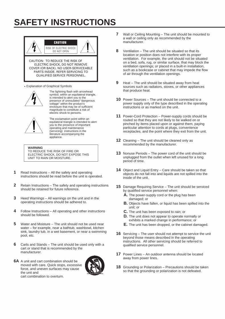
6A A unit and cart combination should bemoved with care. Quick stops, excessiveforce, and uneven surfaces may causethe unit and cart combination to overturn.
7 Wall or Ceiling Mounting – The unit should be mounted toa wall or ceiling only as recommended by themanufacturer.
8 Ventilation – The unit should be situated so that itslocation or position does not interfere with its properventilation. For example, the unit should not be situatedon a bed, sofa, rug, or similar surface, that may block theventilation openings; or placed in a built-in installation,such as a bookcase or cabinet that may impede the flowof air through the ventilation openings.
9 Heat – The unit should be situated away from heatsources such as radiators, stoves, or other appliancesthat produce heat.
10 Power Sources – The unit should be connected to apower supply only of the type described in the operatinginstructions or as marked on the unit.
11 Power-Cord Protection – Power-supply cords should berouted so that they are not likely to be walked on orpinched by items placed upon or against them, payingparticular attention to cords at plugs, conveniencereceptacles, and the point where they exit from the unit.
12 Cleaning – The unit should be cleaned only asrecommended by the manufacturer.
13 Nonuse Periods – The power cord of the unit should beunplugged from the outlet when left unused for a longperiod of time.
14 Object and Liquid Entry – Care should be taken so thatobjects do not fall into and liquids are not spilled into theinside of the unit.
15 Damage Requiring Service – The unit should be servicedby qualified service personnel when:A. The power-supply cord or the plug has been
damaged; orB. Objects have fallen, or liquid has been spilled into the
unit; orC. The unit has been exposed to rain; orD. The unit does not appear to operate normally or
exhibits a marked change in performance; orE. The unit has been dropped, or the cabinet damaged.
16 Servicing – The user should not attempt to service the unitbeyond those means described in the operatinginstructions. All other servicing should be referred toqualified service personnel.
17 Power Lines – An outdoor antenna should be locatedaway from power lines.
18 Grounding or Polarization – Precautions should be takenso that the grounding or polarization is not defeated.
SAFETY INSTRUCTIONS
RISK OF ELECTRIC SHOCKDO NOT OPEN
CAUTION: TO REDUCE THE RISK OFELECTRIC SHOCK, DO NOT REMOVE
COVER (OR BACK). NO USER-SERVICEABLEPARTS INSIDE. REFER SERVICING TO
QUALIFIED SERVICE PERSONNEL.
The lightning flash with arrowheadsymbol, within an equilateral triangle,is intended to alert you to thepresence of uninsulated “dangerousvoltage” within the product’senclosure that may be of sufficientmagnitude to constitute a risk ofelectric shock to persons.
The exclamation point within anequilateral triangle is intended to alertyou to the presence of importantoperating and maintenance(servicing) instructions in theliterature accompanying theappliance.
• Explanation of Graphical Symbols
CAUTION
WARNINGTO REDUCE THE RISK OF FIRE ORELECTRIC SHOCK, DO NOT EXPOSE THISUNIT TO RAIN OR MOISTURE.
1
En
glish
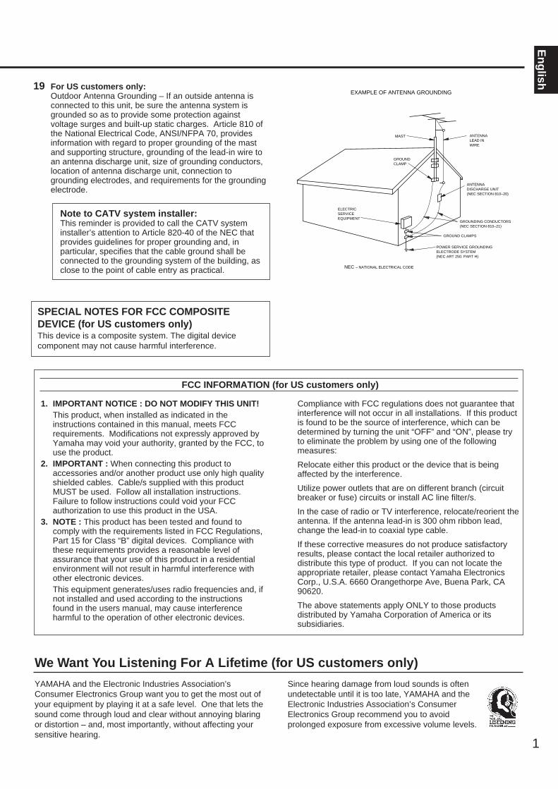
Note to CATV system installer:This reminder is provided to call the CATV systeminstaller’s attention to Article 820-40 of the NEC thatprovides guidelines for proper grounding and, in particular, specifies that the cable ground shall beconnected to the grounding system of the building, asclose to the point of cable entry as practical.
SPECIAL NOTES FOR FCC COMPOSITEDEVICE (for US customers only)This device is a composite system. The digital devicecomponent may not cause harmful interference.
19 For US customers only:Outdoor Antenna Grounding – If an outside antenna isconnected to this unit, be sure the antenna system isgrounded so as to provide some protection againstvoltage surges and built-up static charges. Article 810 ofthe National Electrical Code, ANSI/NFPA 70, providesinformation with regard to proper grounding of the mastand supporting structure, grounding of the lead-in wire toan antenna discharge unit, size of grounding conductors,location of antenna discharge unit, connection togrounding electrodes, and requirements for the groundingelectrode.
EXAMPLE OF ANTENNA GROUNDING
MAST
GROUNDCLAMP
ANTENNALEAD INWIRE
ANTENNADISCHARGE UNIT(NEC SECTION 810–20)
GROUNDING CONDUCTORS(NEC SECTION 810–21)
GROUND CLAMPS
POWER SERVICE GROUNDINGELECTRODE SYSTEM(NEC ART 250. PART H)
ELECTRICSERVICEEQUIPMENT
NEC – NATIONAL ELECTRICAL CODE
1. IMPORTANT NOTICE : DO NOT MODIFY THIS UNIT!This product, when installed as indicated in theinstructions contained in this manual, meets FCCrequirements. Modifications not expressly approved byYamaha may void your authority, granted by the FCC, touse the product.
2. IMPORTANT : When connecting this product toaccessories and/or another product use only high qualityshielded cables. Cable/s supplied with this productMUST be used. Follow all installation instructions.Failure to follow instructions could void your FCCauthorization to use this product in the USA.
3. NOTE : This product has been tested and found tocomply with the requirements listed in FCC Regulations,Part 15 for Class “B” digital devices. Compliance withthese requirements provides a reasonable level ofassurance that your use of this product in a residentialenvironment will not result in harmful interference withother electronic devices.This equipment generates/uses radio frequencies and, ifnot installed and used according to the instructionsfound in the users manual, may cause interferenceharmful to the operation of other electronic devices.
Compliance with FCC regulations does not guarantee thatinterference will not occur in all installations. If this productis found to be the source of interference, which can bedetermined by turning the unit “OFF” and “ON”, please tryto eliminate the problem by using one of the followingmeasures:
Relocate either this product or the device that is beingaffected by the interference.
Utilize power outlets that are on different branch (circuitbreaker or fuse) circuits or install AC line filter/s.
In the case of radio or TV interference, relocate/reorient theantenna. If the antenna lead-in is 300 ohm ribbon lead,change the lead-in to coaxial type cable.
If these corrective measures do not produce satisfactoryresults, please contact the local retailer authorized todistribute this type of product. If you can not locate theappropriate retailer, please contact Yamaha ElectronicsCorp., U.S.A. 6660 Orangethorpe Ave, Buena Park, CA90620.
The above statements apply ONLY to those productsdistributed by Yamaha Corporation of America or itssubsidiaries.
FCC INFORMATION (for US customers only)
YAMAHA and the Electronic Industries Association’sConsumer Electronics Group want you to get the most out ofyour equipment by playing it at a safe level. One that lets thesound come through loud and clear without annoying blaringor distortion – and, most importantly, without affecting yoursensitive hearing.
Since hearing damage from loud sounds is oftenundetectable until it is too late, YAMAHA and theElectronic Industries Association’s ConsumerElectronics Group recommend you to avoidprolonged exposure from excessive volume levels.
We Want You Listening For A Lifetime (for US customers only)
2
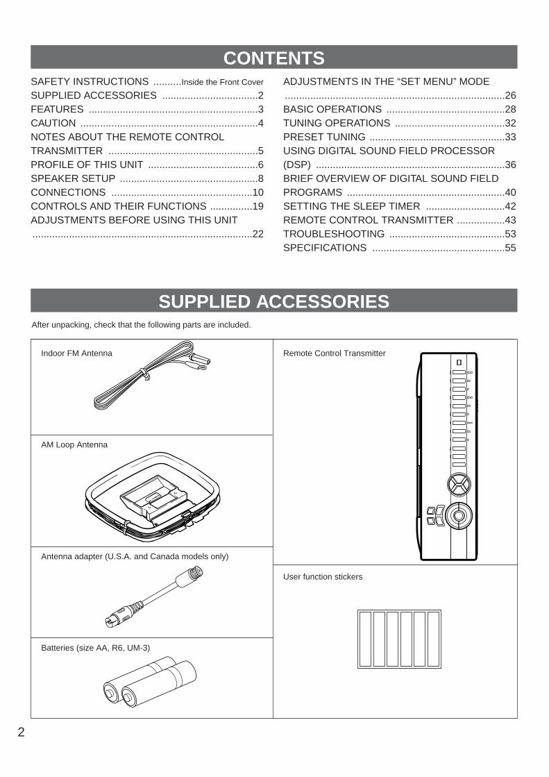
After unpacking, check that the following parts are included.
SAFETY INSTRUCTIONS ..........Inside the Front Cover
SUPPLIED ACCESSORIES ..................................2FEATURES ............................................................3CAUTION ...............................................................4NOTES ABOUT THE REMOTE CONTROLTRANSMITTER .....................................................5PROFILE OF THIS UNIT .......................................6SPEAKER SETUP .................................................8CONNECTIONS ..................................................10CONTROLS AND THEIR FUNCTIONS ...............19ADJUSTMENTS BEFORE USING THIS UNIT ..............................................................................22
ADJUSTMENTS IN THE “SET MENU” MODE ..............................................................................26BASIC OPERATIONS ..........................................28TUNING OPERATIONS .......................................32PRESET TUNING ................................................33USING DIGITAL SOUND FIELD PROCESSOR(DSP) ...................................................................36BRIEF OVERVIEW OF DIGITAL SOUND FIELDPROGRAMS ........................................................40SETTING THE SLEEP TIMER ............................42REMOTE CONTROL TRANSMITTER .................43TROUBLESHOOTING .........................................53SPECIFICATIONS ...............................................55
Indoor FM Antenna
AM Loop Antenna
Antenna adapter (U.S.A. and Canada models only)
Batteries (size AA, R6, UM-3)
Remote Control Transmitter
User function stickers
CONTENTS
SUPPLIED ACCESSORIES
3
En
glish 5 Speaker Configuration
Main: 80W + 80W (8Ω) RMS Output
Power, 0.04% THD, 20–20,000 Hz
Center: 80W (8Ω) RMS Output Power,
0.07% THD, 20–20,000 Hz
Rear: 80W + 80W (8Ω) RMS Output
Power, 0.07% THD, 20–20,000 Hz
Digital Sound Field Processor
Dolby Digital (AC-3) Decoder
Dolby Pro Logic Surround Decoder
Theater-like Sound Experience by the
Combination of Dolby Surround and
YAMAHA DSP Technology (CINEMA DSP)
Automatic Input Balance Control for
Dolby Pro Logic Surround
Test Tone Generator for Easier Speaker
Balance Adjustment
3 Center Channel Modes
(NORMAL/WIDE/PHANTOM)
BASS EXTENSION Switch for Reinforcing
Bass Response
40-Station Random Access Preset Tuning
Automatic Preset Tuning
Preset Station Shifting Capability (Preset
Editing)
IF Count Direct PLL Synthesizer Tuning
System
Video Signal Input/Output Capability
(Including S Video Connections)
SLEEP Timer
On Screen Display Function Helpful in
Controlling This Unit
“Learning” Remote Control Transmitter
FEATURES

1. To assure the finest performance, please read this manualcarefully. Keep it in a safe place for future reference.
2. Install this unit in a cool, dry, clean place – away fromwindows, heat sources, sources of excessive vibration,dust, moisture and cold. Avoid sources of humming(transformers, motors). To prevent fire or electrical shock,do not expose the unit to rain or water.
3. Never open the cabinet. If something drops into the set,contact your dealer.
4. Do not use force on switches, controls or connection wires.When moving the unit, first disconnect the power plug andthe wires connected to other equipment. Never pull thewires themselves.
5. The openings on the cabinet assure proper ventilation ofthe unit. If these openings are obstructed, the temperatureinside the cabinet will rise rapidly. Therefore, avoid placingobjects against these openings, and install the unit in well-ventilated condition. Make sure to allow a space of at least20 cm behind, 20 cm on the both sides and 30 cm abovethe top panel of the unit. Otherwise it may not only damagethe unit, but also cause fire.
6. Always set the VOLUME control to “– ∞” before startingthe audio source play. Increase the volume gradually to anappropriate level after playback has been started.
7. Do not attempt to clean the unit with chemical solvents;this might damage the finish. Use a clean, dry cloth.
8. Be sure to read the “TROUBLESHOOTING” sectionregarding common operating errors before concluding thatthe unit is faulty.
9. When not planning to use this unit for long periods of time(ie., vacation, etc.), disconnect the AC power plug from thewall outlet.
10. To prevent lightning damage, disconnect the AC powerplug and disconnect the antenna cable when there is anelectrical storm.
11. Grounding or polarization – Precautions should be takenso that the grounding or polarization of an appliance is notdefeated.
12. AC outletDo not connect audio equipment to the AC outlet on therear panel if that equipment requires more power than theoutlet is rated to provide.
13. Voltage Selector (China and General Models only)The voltage selector on the rear panel of this unit mustbe set for your local main voltage BEFORE plugginginto the AC main supply.Voltages are 110/120/220/240 V AC, 50/60 Hz.
This unit is not disconnected from the AC power source aslong as it is connected to the wall outlet, even if this unititself is turned off. This state is called the standby mode.In this state, this unit is designed to consume a very smallquantity of power.
IMPORTANTPlease record the serial number of this unit in the spacebelow.
Serial No.:
The serial number is located on the rear of the unit.Retain this Owner’s Manual in a safe place for futurereference.
WARNINGTO REDUCE THE RISK OF FIRE OR ELECTRIC SHOCK,DO NOT EXPOSE THIS UNIT TO RAIN OR MOISTURE.
FREQUENCY STEP switch (China and General Modelsonly)Because the interstation frequency spacing differs indifferent areas, set the FREQUENCY STEP switch (locatedat the rear) according to the frequency spacing in your area.Before setting this switch, disconnect the AC power plug ofthis unit from the AC outlet.
FOR CANADIAN CUSTOMERS
TO PREVENT ELECTRIC SHOCK, MATCH WIDE BLADEOF PLUG TO WIDE SLOT AND FULLY INSERT.
THIS CLASS B DIGITAL APPARATUS MEETS ALLREQUIREMENTS OF THE CANADIAN INTERFERENCE-CAUSING EQUIPMENT REGULATIONS.
WARNINGDo not change the IMPEDANCE SELECTOR switchsetting while the power to this unit is on, otherwise thisunit may be damaged.
IF THIS UNIT FAILS TO TURN ON WHEN THESTANDBY/ON SWITCH IS PRESSEDThe IMPEDANCE SELECTOR switch may not be set toeither end closely. If so, set the switch to either end closely.
4
SWITCHEDI20V 60Hz
I00W MAX. TOTAL
AC OUTLETS
IMPEDANCE SELECTOR
: 6ΩMIN. /SPEAKERSINGLE: 6ΩMIN. /SPEAKER
DUAL: 3ΩMIN. /SPEAKERA OR B: 4ΩMIN. /SPEAKER
A B: 8ΩMIN. /SPEAKER
SET BEFORE POWER ON
REARCENTER
MAIN
: 8ΩMIN. /SPEAKERSINGLE: 8ΩMIN. /SPEAKER
DUAL: 4ΩMIN. /SPEAKERA OR B: 8ΩMIN. /SPEAKER
A B:I6ΩMIN. /SPEAKER
REARCENTER
MAIN
IMPEDANCE SELECTOR
(U.S.A. model)
CAUTION : READ THIS BEFORE OPERATING YOUR UNIT.
5
En
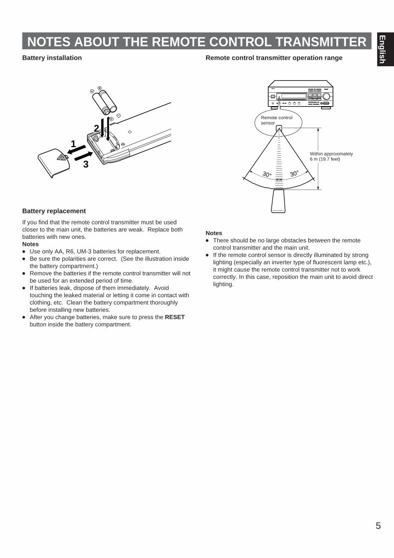
glishBattery installation
Battery replacement
If you find that the remote control transmitter must be usedcloser to the main unit, the batteries are weak. Replace bothbatteries with new ones.Notes Use only AA, R6, UM-3 batteries for replacement. Be sure the polarities are correct. (See the illustration inside
the battery compartment.) Remove the batteries if the remote control transmitter will not
be used for an extended period of time. If batteries leak, dispose of them immediately. Avoid
touching the leaked material or letting it come in contact withclothing, etc. Clean the battery compartment thoroughlybefore installing new batteries.
After you change batteries, make sure to press the RESETbutton inside the battery compartment.
Remote control transmitter operation range
Notes There should be no large obstacles between the remote
control transmitter and the main unit. If the remote control sensor is directly illuminated by strong
lighting (especially an inverter type of fluorescent lamp etc.),it might cause the remote control transmitter not to workcorrectly. In this case, reposition the main unit to avoid directlighting.
l620
28
40
60
l2
8
4
2
0–dB
30° 30°
Remote controlsensor
Within approximately6 m (19.7 feet)
1
3
2
NOTES ABOUT THE REMOTE CONTROL TRANSMITTER
6
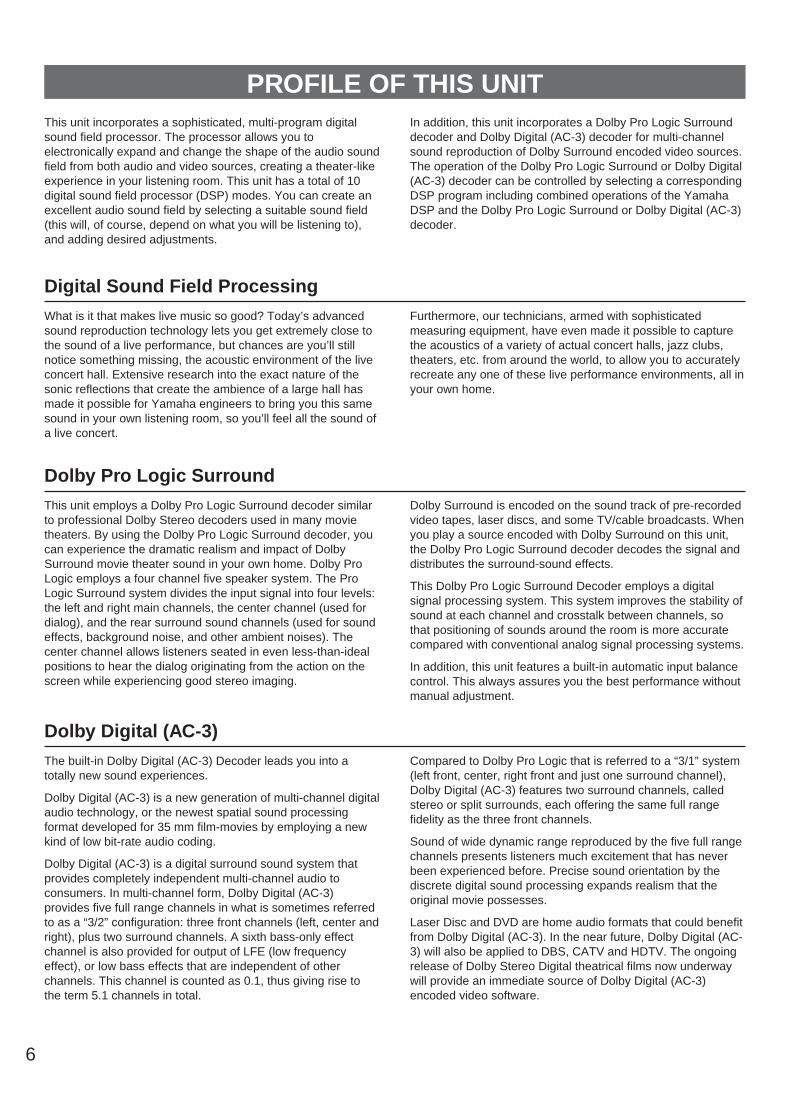
PROFILE OF THIS UNITThis unit incorporates a sophisticated, multi-program digitalsound field processor. The processor allows you toelectronically expand and change the shape of the audio soundfield from both audio and video sources, creating a theater-likeexperience in your listening room. This unit has a total of 10digital sound field processor (DSP) modes. You can create anexcellent audio sound field by selecting a suitable sound field(this will, of course, depend on what you will be listening to),and adding desired adjustments.
In addition, this unit incorporates a Dolby Pro Logic Surrounddecoder and Dolby Digital (AC-3) decoder for multi-channelsound reproduction of Dolby Surround encoded video sources.The operation of the Dolby Pro Logic Surround or Dolby Digital(AC-3) decoder can be controlled by selecting a correspondingDSP program including combined operations of the YamahaDSP and the Dolby Pro Logic Surround or Dolby Digital (AC-3)decoder.
Digital Sound Field ProcessingWhat is it that makes live music so good? Today’s advancedsound reproduction technology lets you get extremely close tothe sound of a live performance, but chances are you’ll stillnotice something missing, the acoustic environment of the liveconcert hall. Extensive research into the exact nature of thesonic reflections that create the ambience of a large hall hasmade it possible for Yamaha engineers to bring you this samesound in your own listening room, so you’ll feel all the sound ofa live concert.
Furthermore, our technicians, armed with sophisticatedmeasuring equipment, have even made it possible to capturethe acoustics of a variety of actual concert halls, jazz clubs,theaters, etc. from around the world, to allow you to accuratelyrecreate any one of these live performance environments, all inyour own home.
Dolby Pro Logic SurroundThis unit employs a Dolby Pro Logic Surround decoder similarto professional Dolby Stereo decoders used in many movietheaters. By using the Dolby Pro Logic Surround decoder, youcan experience the dramatic realism and impact of DolbySurround movie theater sound in your own home. Dolby ProLogic employs a four channel five speaker system. The ProLogic Surround system divides the input signal into four levels:the left and right main channels, the center channel (used fordialog), and the rear surround sound channels (used for soundeffects, background noise, and other ambient noises). Thecenter channel allows listeners seated in even less-than-idealpositions to hear the dialog originating from the action on thescreen while experiencing good stereo imaging.
Dolby Surround is encoded on the sound track of pre-recordedvideo tapes, laser discs, and some TV/cable broadcasts. Whenyou play a source encoded with Dolby Surround on this unit,the Dolby Pro Logic Surround decoder decodes the signal anddistributes the surround-sound effects.
This Dolby Pro Logic Surround Decoder employs a digitalsignal processing system. This system improves the stability ofsound at each channel and crosstalk between channels, sothat positioning of sounds around the room is more accuratecompared with conventional analog signal processing systems.
In addition, this unit features a built-in automatic input balancecontrol. This always assures you the best performance withoutmanual adjustment.
Dolby Digital (AC-3)The built-in Dolby Digital (AC-3) Decoder leads you into atotally new sound experiences.
Dolby Digital (AC-3) is a new generation of multi-channel digitalaudio technology, or the newest spatial sound processingformat developed for 35 mm film-movies by employing a newkind of low bit-rate audio coding.
Dolby Digital (AC-3) is a digital surround sound system thatprovides completely independent multi-channel audio toconsumers. In multi-channel form, Dolby Digital (AC-3)provides five full range channels in what is sometimes referredto as a “3/2” configuration: three front channels (left, center andright), plus two surround channels. A sixth bass-only effectchannel is also provided for output of LFE (low frequencyeffect), or low bass effects that are independent of otherchannels. This channel is counted as 0.1, thus giving rise tothe term 5.1 channels in total.
Compared to Dolby Pro Logic that is referred to a “3/1” system(left front, center, right front and just one surround channel),Dolby Digital (AC-3) features two surround channels, calledstereo or split surrounds, each offering the same full rangefidelity as the three front channels.
Sound of wide dynamic range reproduced by the five full rangechannels presents listeners much excitement that has neverbeen experienced before. Precise sound orientation by thediscrete digital sound processing expands realism that theoriginal movie possesses.
Laser Disc and DVD are home audio formats that could benefitfrom Dolby Digital (AC-3). In the near future, Dolby Digital (AC-3) will also be applied to DBS, CATV and HDTV. The ongoingrelease of Dolby Stereo Digital theatrical films now underwaywill provide an immediate source of Dolby Digital (AC-3)encoded video software.
7
En
glish
Dolby Surround + DSP (CINEMA DSP)
Dolby Surround sound system shows its full ability in a largemovie theater, because movie sounds are originally designedto be reproduced in a large movie theater using manyspeakers. It is difficult to create a sound environment similar tothat of a movie theater in your listening room, because theroom size, materials of inside walls, the number of speakers,etc. of your listening room is much different from those of amovie theater.
Yamaha DSP technology made it possible to present you withnearly the same sound experience as that of a large movietheater in your listening room by compensating for lack ofpresence and dynamics in your listening room with its originaldigital sound fields combined with Dolby Surround sound field.
The YAMAHA “CINEMA DSP” logo indicates those programsare created by the combination of Dolby Surround andYAMAHA DSP technology.
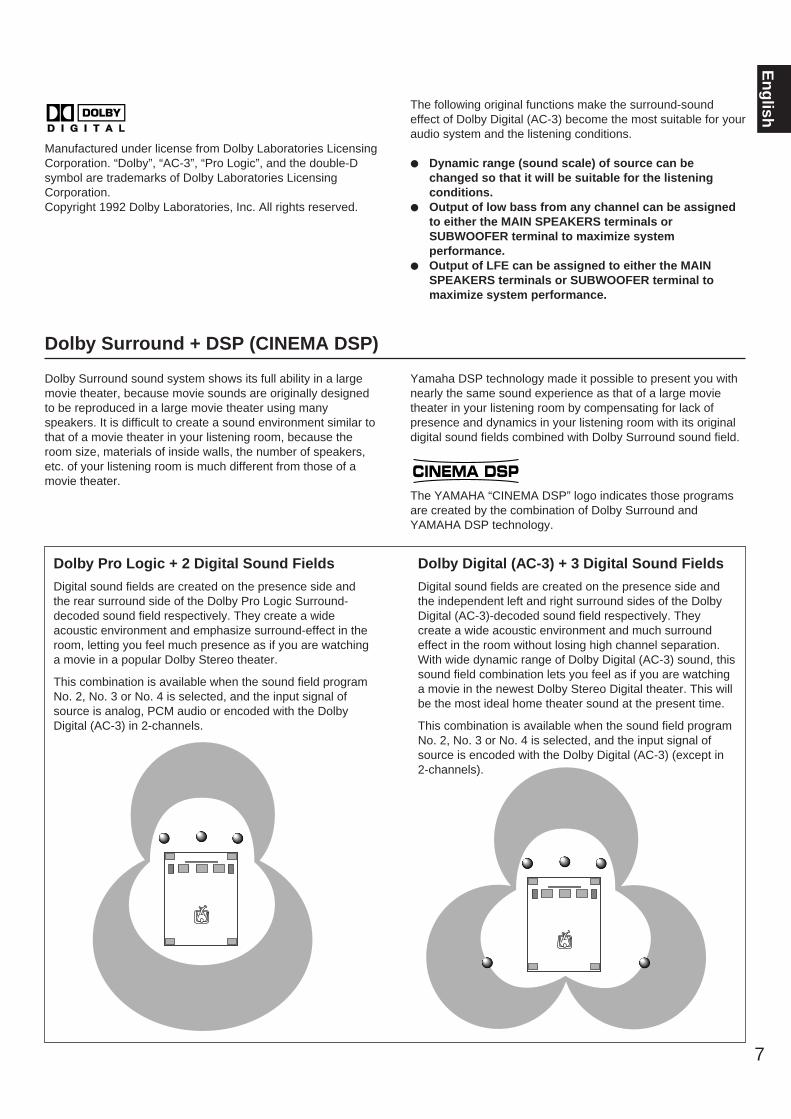
Manufactured under license from Dolby Laboratories LicensingCorporation. “Dolby”, “AC-3”, “Pro Logic”, and the double-Dsymbol are trademarks of Dolby Laboratories LicensingCorporation.Copyright 1992 Dolby Laboratories, Inc. All rights reserved.
The following original functions make the surround-soundeffect of Dolby Digital (AC-3) become the most suitable for youraudio system and the listening conditions.
Dynamic range (sound scale) of source can bechanged so that it will be suitable for the listeningconditions.
Output of low bass from any channel can be assignedto either the MAIN SPEAKERS terminals orSUBWOOFER terminal to maximize systemperformance.
Output of LFE can be assigned to either the MAINSPEAKERS terminals or SUBWOOFER terminal tomaximize system performance.
Dolby Pro Logic + 2 Digital Sound Fields
Digital sound fields are created on the presence side andthe rear surround side of the Dolby Pro Logic Surround-decoded sound field respectively. They create a wideacoustic environment and emphasize surround-effect in theroom, letting you feel much presence as if you are watchinga movie in a popular Dolby Stereo theater.
This combination is available when the sound field programNo. 2, No. 3 or No. 4 is selected, and the input signal ofsource is analog, PCM audio or encoded with the DolbyDigital (AC-3) in 2-channels.
Dolby Digital (AC-3) + 3 Digital Sound Fields
Digital sound fields are created on the presence side andthe independent left and right surround sides of the DolbyDigital (AC-3)-decoded sound field respectively. Theycreate a wide acoustic environment and much surroundeffect in the room without losing high channel separation.With wide dynamic range of Dolby Digital (AC-3) sound, thissound field combination lets you feel as if you are watchinga movie in the newest Dolby Stereo Digital theater. This willbe the most ideal home theater sound at the present time.
This combination is available when the sound field programNo. 2, No. 3 or No. 4 is selected, and the input signal ofsource is encoded with the Dolby Digital (AC-3) (except in2-channels).
CINEMA DSP
8
SPEAKER SETUPSPEAKERS TO BE USED
SPEAKER CONFIGURATION
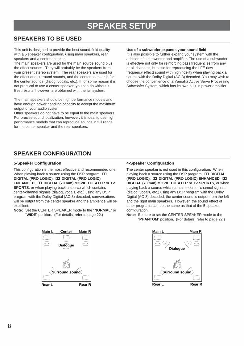
5-Speaker Configuration
This configuration is the most effective and recommended one.When playing back a source using the DSP program, DIGITAL (PRO LOGIC), DIGITAL (PRO LOGIC)ENHANCED, DIGITAL (70 mm) MOVIE THEATER or TVSPORTS, or when playing back a source which containscenter-channel signals (dialog, vocals, etc.) using any DSPprogram with the Dolby Digital (AC-3) decoded, conversationswill be output from the center speaker and the ambience will beexcellent.Note: Set the CENTER SPEAKER mode to the “NORMAL” or
“WIDE” position. (For details, refer to page 22.)
4-Speaker Configuration
The center speaker is not used in this configuration. Whenplaying back a source using the DSP program, DIGITAL(PRO LOGIC), DIGITAL (PRO LOGIC) ENHANCED, DIGITAL (70 mm) MOVIE THEATER or TV SPORTS, or whenplaying back a source which contains center-channel signals(dialog, vocals, etc.) using any DSP program with the DolbyDigital (AC-3) decoded, the center sound is output from the leftand the right main speakers. However, the sound effect ofother programs can be the same as that of the 5-speakerconfiguration.Note: Be sure to set the CENTER SPEAKER mode to the
“PHANTOM” position. (For details, refer to page 22.)
Front L Center Front R
Dialogue
Surround sound
Dialogue
Surround sound
Rear L Rear R
Front L Front R
Dialogue
Surround sound
Dialogue
Surround sound
Rear L Rear R
Main L Main RMain L Main R
This unit is designed to provide the best sound-field qualitywith a 5 speaker configuration, using main speakers, rearspeakers and a center speaker. The main speakers are used for the main source sound plusthe effect sounds. They will probably be the speakers fromyour present stereo system. The rear speakers are used forthe effect and surround sounds, and the center speaker is forthe center sounds (dialog, vocals, etc.). If for some reason it isnot practical to use a center speaker, you can do without it.Best results, however, are obtained with the full system.
The main speakers should be high performance models andhave enough power handling capacity to accept the maximumoutput of your audio system.Other speakers do not have to be equal to the main speakers.For precise sound localization, however, it is ideal to use highperformance models that can reproduce sounds in full rangefor the center speaker and the rear speakers.
Use of a subwoofer expands your sound fieldIt is also possible to further expand your system with theaddition of a subwoofer and amplifier. The use of a subwooferis effective not only for reinforcing bass frequencies from anyor all channels, but also for reproducing the LFE (lowfrequency effect) sound with high fidelity when playing back asource with the Dolby Digital (AC-3) decoded. You may wish tochoose the convenience of a Yamaha Active Servo ProcessingSubwoofer System, which has its own built-in power amplifier.

9
En
glishSPEAKER PLACEMENT
When you place speakers, refer to the following.
Main: In normal position. (The position of your presentstereo speaker system.)
Rear: Behind your listening position, facing slightly inward.Nearly 1.8 m (approx. 6 feet) up from the floor.
Center: Precisely between the main speakers. (To avoidinterference with TV sets, use a magnetically shieldedspeaker.)
Subwoofer:The position of the subwoofer is not so criticalbecause low bass tones are not highly directional.
Main speaker Center speaker Rear speaker
Subwoofer
10
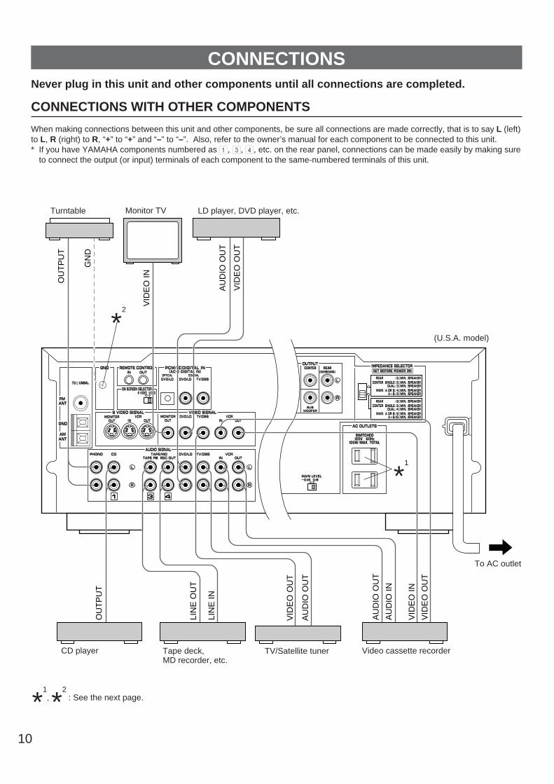
CONNECTIONSNever plug in this unit and other components until all connections are completed.
CONNECTIONS WITH OTHER COMPONENTS
When making connections between this unit and other components, be sure all connections are made correctly, that is to say L (left)to L, R (right) to R, “+” to “+” and “–” to “–”. Also, refer to the owner’s manual for each component to be connected to this unit.* If you have YAMAHA components numbered as 1, 3, 4, etc. on the rear panel, connections can be made easily by making sure
to connect the output (or input) terminals of each component to the same-numbered terminals of this unit.
*1
, *2
: See the next page.
FMANT
AMANT
GND
75Ω UNBAL.
GND
MONITOROUT
DVD/LD TV/DBSIN OUT
VCRVIDEO SIGNALS VIDEO SIGNAL
MONITOROUT IN OUT
VCR
MAIN CENTER REAR(SURROUND)
OUTPUT
SUBWOOFER
ON SCREEN SELECTORS VIDEO VIDEO
SWITCHEDI20V 60Hz
I00W MAX. TOTAL
AC OUTLETS
REMOTE CONTROLIN OUT
COAXIALDVD/LD
OPTICALDVD/LD TV/DBS
PCM/ DIGITAL IN(AC–3 DIGITAL IN)
PHONO CD TAPE/MD DVD/LD TV/DBS VCRTAPE PB REC OUT IN OUT
AUDIO SIGNAL
1 3 4
—I0dB 0dBMAIN LEVEL
IMPEDANCE SELECTOR
: 6ΩMIN. /SPEAKERSINGLE: 6ΩMIN. /SPEAKER
DUAL: 3ΩMIN. /SPEAKERA OR B: 4ΩMIN. /SPEAKER
A B: 8ΩMIN. /SPEAKER
SET BEFORE POWER ON
REARCENTER
MAIN
: 8ΩMIN. /SPEAKERSINGLE: 8ΩMIN. /SPEAKER
DUAL: 4ΩMIN. /SPEAKERA OR B: 8ΩMIN. /SPEAKER
A B:I6ΩMIN. /SPEAKER
REARCENTER
MAIN
VID
EO
IN
GN
D
OU
TP
UT
OU
TP
UT
LIN
E O
UT
LIN
E IN
AU
DIO
OU
T
VID
EO
OU
T
VID
EO
OU
T
AU
DIO
OU
T
AU
DIO
OU
T
AU
DIO
IN
VID
EO
IN
VID
EO
OU
T
(U.S.A. model)
To AC outlet
Turntable LD player, DVD player, etc.
Video cassette recorderTV/Satellite tunerTape deck, MD recorder, etc.
CD player
Monitor TV
*2
*1
11
En
glish
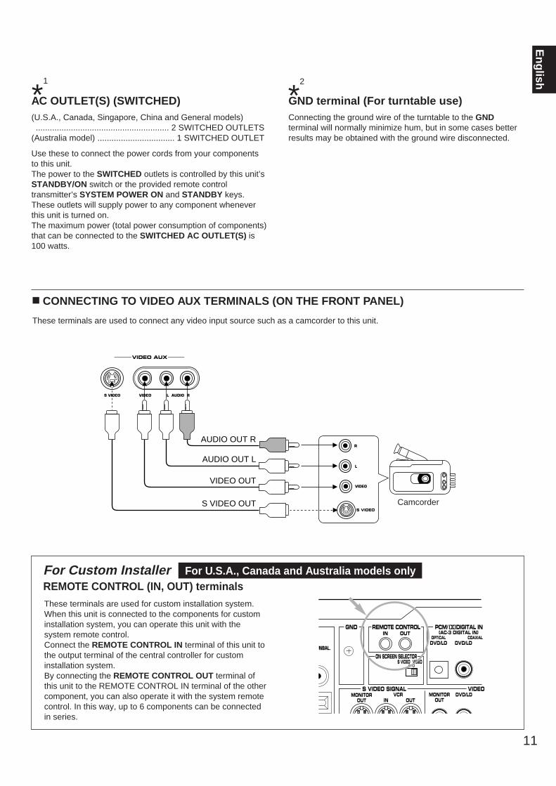
AC OUTLET(S) (SWITCHED)(U.S.A., Canada, Singapore, China and General models)......................................................... 2 SWITCHED OUTLETS
(Australia model) ................................. 1 SWITCHED OUTLET
Use these to connect the power cords from your componentsto this unit.The power to the SWITCHED outlets is controlled by this unit’sSTANDBY/ON switch or the provided remote controltransmitter’s SYSTEM POWER ON and STANDBY keys.These outlets will supply power to any component wheneverthis unit is turned on.The maximum power (total power consumption of components)that can be connected to the SWITCHED AC OUTLET(S) is100 watts.
GND terminal (For turntable use)Connecting the ground wire of the turntable to the GNDterminal will normally minimize hum, but in some cases betterresults may be obtained with the ground wire disconnected.
n CONNECTING TO VIDEO AUX TERMINALS (ON THE FRONT PANEL)
These terminals are used to connect any video input source such as a camcorder to this unit.
S VIDEO
L
R
VIDEO
VIDEO AUX
S VIDEO VIDEO L AUDIO R
VIDEO OUT
S VIDEO OUT
AUDIO OUT L
AUDIO OUT R
*1
*2
For Custom Installer For U.S.A., Canada and Australia models onlyREMOTE CONTROL (IN, OUT) terminals These terminals are used for custom installation system.When this unit is connected to the components for custominstallation system, you can operate this unit with thesystem remote control.Connect the REMOTE CONTROL IN terminal of this unit tothe output terminal of the central controller for custominstallation system.By connecting the REMOTE CONTROL OUT terminal ofthis unit to the REMOTE CONTROL IN terminal of the othercomponent, you can also operate it with the system remotecontrol. In this way, up to 6 components can be connectedin series.
Ω UNBAL.
GND
MONITOROUT
DVD/LDS VIDEO SIGNAL VIDEO S
MONITOROUT IN OUT
VCR
ON SCREEN SELECTORS VIDEO VIDEO
REMOTE CONTROLIN OUT (AC-3 DIGITAL IN)
COAXIALDVD/LD
OPTICALDVD/LD
PCM/ DIGITAL IN
Camcorder

12
n CONNECTING TO DIGITAL (OPTICAL AND COAXIAL) TERMINALS
If your DVD (LD) player, TV/satellite tuner, etc. are equippedwith coaxial or optical digital audio signal output terminals, theycan be connected to this unit’s COAXIAL and/or OPTICALdigital signal input terminals.
To make a connection between optical digital audio signalterminals, remove the cover from each terminal, and thenconnect them by using a commercially available optical fibercable that conforms to EIAJ standards. Other cables might notfunction correctly.
Even if you connect an audio/video unit to the OPTICAL (orCOAXIAL) terminal of this unit, you must keep the unitconnected with the same named analog audio signal terminalsof this unit, because digital signal cannot be recorded by a tapedeck or VCR connected to this unit. You can switch theselection of input signals between “digital” and “analog” easily.(See page 29 for details.)
Notes When connecting an audio/video unit to both of the digital
and analog terminals of this unit, make sure to connect toboth terminals of the same name.
Be sure to attach the covers when the OPTICAL terminalsare not being used, in order to protect the terminals fromdust.
All digital audio signal input terminals are applicable to thesampling frequency of 32 kHz, 44.1 kHz and 48 kHz.
FMANT
AMANT
GND
75Ω UNBAL.
GND
MONITOROUT
DVD/LD TV/DBSIN OUT
VCRVIDEO SIGNALS VIDEO SIGNAL
MONITOROUT IN OUT
VCR
ON SCREEN SELECTORS VIDEO VIDEO
REMOTE CONTROLIN OUT
COAXIALDVD/LD
OPTICALDVD/LD TV/DBS
PCM/ DIGITAL IN(AC–3 DIGITAL IN)
PHONO CD TAPE/MD DVD/LD TV/DBS VCRTAPE PB REC OUT IN OUT
AUDIO SIGNAL
1 3 4
COAXIALDIGITAL OUT
OPTICALDIGITAL
OUT
COAXIALDIGITAL
OUT
ANALOGOUT
ANALOGOUT
DVD (LD) player TV/Satellite tuner
(U.S.A. model)

If your LD player has AC-3 RF signal output terminal and nodigital signal output terminal for AC-3 discrete audio signals,connect the AC-3 RF signal output terminal to this unit’sOPTICAL (or COAXIAL) digital signal input terminal by usingan RF demodulator (separate purchase).First, connect the AC-3 RF signal output terminal of the LDplayer to the AC-3 RF signal input terminal of the RFdemodulator. Next, connect the optical (or coaxial) digitalsignal output terminal of the RF demodulator to the OPTICAL(or COAXIAL) digital signal input terminal of this unit.This connection is necessary for sending audio signalsencoded with the Dolby Digital (AC-3) from the LD player tothis unit.
It is also necessary to connect the LD player to this unit’sanalog audio signal input terminals regardless of the AC-3 RFsignal connection, for playing back an LD source with theDolby Pro Logic Surround decoded or in normal stereo (ormonaural).
If desired, you can also connect the digital signal outputterminal (for 2-channel audio signals) of the LD player to thisunit. If you will do so, connect it to the COAXIAL digital signalinput terminal of this unit, and connect the RF demodulator tothe OPTICAL digital signal input terminal of this unit.By this connection, if the input mode of the DVD/LD source isin “AUTO”, you can enjoy listening to sounds with the DolbyDigital (AC-3) decoded when you play a disc encoded with theDolby Digital (AC-3) though signals are input to both OPTICALand COAXIAL digital signal input terminals of this unitsimultaneously (because signals input to the OPTICAL terminaltake priority of signals input to the COAXIAL terminal).See page 29 for details about switching the input mode.
FMANT
AMANT
GND
75Ω UNBAL.
GND
MONITOROUT
DVD/LD TV/DBSIN OUT
VCRVIDEO SIGNALS VIDEO SIGNAL
MONITOROUT IN OUT
VCR
ON SCREEN SELECTORS VIDEO VIDEO
REMOTE CONTROLIN OUT
COAXIALDVD/LD
OPTICALDVD/LD TV/DBS
PCM/ DIGITAL IN(AC–3 DIGITAL IN)
PHONO CD TAPE/MD DVD/LD TV/DBS VCRTAPE PB REC OUT IN OUT
AUDIO SIGNAL
1 3 4
COAXIAL DIGITAL OUT
COAXIAL DIGITAL OUT
OPTICALDIGITAL OUT
AC-3 RF OUT
AC-3 RF IN
ANALOG OUT
13
En
glish
Notes on connecting with an LD player equipped with an AC-3 RF output
RF demodulator(YAMAHA APD-1 etc.)
(U.S.A. model)
Notes If your LD player has an OPTICAL digital output terminal
(for 2-channel audio signals), be sure not to connect it tothis unit’s OPTICAL digital input terminal. If you do so,when you play a disc encoded with the Dolby Digital (AC-3),the Dolby Digital (AC-3) will not be decoded because the 2-channel audio signals input to this unit’s OPTICAL digitalinput terminal are selected prior to the signals encoded withthe Dolby Digital (AC-3) input to this unit’s COAXIAL digitalinput terminal by way of an RF demodulator.
If, for example, you play a CD on the LD player (which canplay a CD also), there is no input to the OPTICAL terminal,so the signals input to the COAXIAL terminal take priority. Inthis case, switch off the RF demodulator to listen to CDsound surely. However, if your RF demodulator is theYamaha model APD-1, you do not have to switch it off.
When you want to play a source encoded with the DolbyDigital (AC-3) without decoding the Dolby Digital (AC-3),you must switch off the power to the RF demodulator.
LD player

14
If you have a video cassette recorder and a monitor equippedwith “S” (high-resolution) video terminals, those terminals canbe connected to this unit’s S VIDEO SIGNAL terminals.Connect the video cassette recorder’s “S” video input andoutput terminals to this unit’s S VIDEO SIGNAL VCR IN andOUT terminals respectively, and connect the monitor’s “S”video input terminal to this unit’s S VIDEO SIGNAL MONITOROUT terminal. Otherwise, connect the video cassetterecorder’s composite video terminals to this unit’s compositevideo terminals, and connect the monitor’s composite videoinput terminal to this unit’s composite MONITOR OUT terminal.
NoteIf video signals are sent to both S VIDEO SIGNAL inputand composite input terminals, the signals will be sent totheir respective output terminals. MONITOR
OUTDVD/LD TV/DBS
IN OUTVCR
VIDEO SIGNALS VIDEO SIGNALMONITOR
OUT IN OUTVCR
ON SCREEN SELECTOR
PAL NTSC S VIDEO VIDEOS V
IDE
O IN
VIDEO IN
S V
IDE
OO
UT
S V
IDE
OIN V
IDE
O O
UT
VID
EO
IN
Video cassette recorder
Monitor TV
If you connect a video cassette recorder, LD player, videomonitor, etc. to this unit, you can display DSP programnames and information about other settings and adjustmentson the video monitor screen which is connected to thecomposite VIDEO SIGNAL (or S VIDEO SIGNAL)MONITOR OUT terminal of this unit. Information issuperimposed over the video image.If there is no program material on the monitor, theinformation will be displayed over a monochromaticbackground.
By using the ON SCREEN SELECTOR S VIDEO/VIDEOswitch, select the video monitor connected to the S VIDEOSIGNAL MONITOR OUT terminal or composite VIDEOSIGNAL MONITOR OUT terminal on which you want todisplay the screen display information.
ON SCREEN SELECTOR S VIDEO/VIDEO switch
S VIDEO: In this position, the screen display information isdisplayed on the video monitor connected to theS VIDEO SIGNAL MONITOR OUT terminal.
VIDEO: In this position, the screen display information isdisplayed on the video monitor connected to thecomposite VIDEO SIGNAL MONITOR OUTterminal.
PAL/NTSC switch (China and General models only)
This unit is designed for use with the NTSC and PALtelevision formats. Set this switch to the position for theformat your monitor TV employs.
PAL: Outputs signals in the PAL format no matter whichformat (PAL or NTSC) of video signal is sent froman external video unit to this unit.Set to this position if your monitor TV employs thePAL format.
NTSC: Outputs signals in the NTSC format no matter whichformat (PAL or NTSC) of video signal is sent froman external video unit to this unit.Set to this position if your monitor TV employs theNTSC format.
NoteMake sure to input a video signal which employs the sameformat that your monitor TV employs, otherwise a picture willnot be played back normally.
ON SCREEN DISPLAY
(General model)*
1
*2
n CONNECTING TO S VIDEO SIGNAL TERMINALS
*1
*2

15
En
glish
CONNECTING SPEAKERS
MAIN CENTER REAR(SURROUND)
OUTPUT
SUBWOOFER
REAR(SURROUND)
CENTER
C DDUAL
SINGLE
CAUTION SEE INSTRUCTION MANUAL FOR CORRECT SETTING.
MAIN
SPEAKERS
A
B
A
B —I0dB 0dBMAIN LEVEL
IMPEDANCE SELECTOR
: 6ΩMIN. /SPEAKERSINGLE: 6ΩMIN. /SPEAKER
DUAL: 3ΩMIN. /SPEAKERA OR B: 4ΩMIN. /SPEAKER
A B: 8ΩMIN. /SPEAKER
SET BEFORE POWER ON
REARCENTER
MAIN
: 8ΩMIN. /SPEAKERSINGLE: 8ΩMIN. /SPEAKER
DUAL: 4ΩMIN. /SPEAKERA OR B: 8ΩMIN. /SPEAKER
A B:I6ΩMIN. /SPEAKER
REARCENTER
MAIN
Rear speaker Rear speaker
Center speaker
Main speakers B
LeftRight
Left
See thenextpage.
Right
Main speakers A
Subwoofer system
LeftRight
NoteUse speakers with the specified impedance shown on therear of this unit.
Note on main speaker connections:One or two speaker systems can be connected to this unit. Ifyou use only one speaker system, connect it to either theSPEAKERS A or B terminals.
Note on a subwoofer connection:You may wish to add a subwoofer to reinforce low frequenciesor to output low bass sound from the subwoofer channel whenreproducing discrete signals.Connect the SUBWOOFER OUTPUT terminal of this unit tothe INPUT terminal of the subwoofer amplifier, and connect thespeaker terminals of the subwoofer amplifier to the subwoofer.With some subwoofers, including the Yamaha Active ServoProcessing Subwoofer System, the amplifier and subwooferare in the same unit.
Note on center speaker connection:One or two center speakers can be connected to this unit. Ifyou cannot place the center speaker on or under the TV, it isrecommended to use two center speakers and place them onboth sides of the TV to orient the center sound at the centerposition. For connecting two center speakers, follow themethod shown below.
REAR(SURROUND)
CENTER
C DDUAL
SINGLE
Center speaker Center speaker
(U.S.A. model)
16
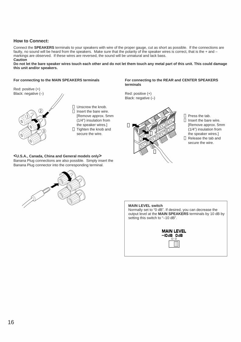
For connecting to the MAIN SPEAKERS terminals
Red: positive (+)Black: negative (–)
➀ Unscrew the knob.➁ Insert the bare wire.
[Remove approx. 5mm(1/4”) insulation fromthe speaker wires.]
➂ Tighten the knob andsecure the wire.
<U.S.A., Canada, China and General models only>Banana Plug connections are also possible. Simply insert theBanana Plug connector into the corresponding terminal.
For connecting to the REAR and CENTER SPEAKERSterminals
Red: positive (+)Black: negative (–)
➀ Press the tab.➁ Insert the bare wire.
[Remove approx. 5mm(1/4”) insulation fromthe speaker wires.]
➂ Release the tab andsecure the wire.
➁
➂
➀
12
3
How to Connect:Connect the SPEAKERS terminals to your speakers with wire of the proper gauge, cut as short as possible. If the connections arefaulty, no sound will be heard from the speakers. Make sure that the polarity of the speaker wires is correct, that is the + and –markings are observed. If these wires are reversed, the sound will be unnatural and lack bass.CautionDo not let the bare speaker wires touch each other and do not let them touch any metal part of this unit. This could damagethis unit and/or speakers.
MAIN LEVEL switchNormally set to “0 dB”. If desired, you can decrease theoutput level at the MAIN SPEAKERS terminals by 10 dB bysetting this switch to “–10 dB”.
—I0dB 0dBMAIN LEVEL

17
En
glish
MAIN OUTPUT terminalsThese terminals are for main channel line output. There is noconnection to these terminals when you use the built-inamplifier.However, if you drive main speakers with an external stereopower amplifier, connect the input terminals of the externalamplifier (MAIN IN or AUX terminals of a power amplifier or anintegrated amplifier) to these terminals.* Output signals from the MAIN OUTPUT terminals are
affected by the use of BASS, TREBLE, BALANCE controlsand BASS EXTENSION switch.
CENTER OUTPUT terminalThis terminal is for center channel line output. There is noconnection to this terminal when you use the built-in amplifier.However, if you drive a center speaker with an external poweramplifier, connect the input terminal of the external amplifier tothis terminal.
REAR (SURROUND) OUTPUT terminalsThese terminals are for rear channel line output. There is noconnection to these terminals when you use the built-inamplifier.However, if you drive rear speakers with an external stereopower amplifier, connect the input terminals of the externalamplifier (MAIN IN or AUX terminals of a power amplifier or anintegrated amplifier) to these terminals.
SUBWOOFER OUTPUT terminalThis terminal is for connecting with the input terminal of anamplifier for driving a subwoofer. When the input signals to this unit are in normal 2-channelstereo, this terminal outputs only frequencies below 150 Hz(200 Hz for General model only) from the main and centerchannels. When discrete signals are input to this unit and areselected as the input source, this terminal outputs signals fromthe subwoofer channel.
NoteOutput level of signals from all of these terminals areadjusted by the use of VOLUME control on the front panelor MASTER VOLUME keys on the remote controltransmitter.
n OUTPUT terminals (for driving speakers with external amplifiers)
Be sure to switch this only when the power to this unit is not on.Select the position whose requirements your speaker systemmeets.
WARNINGDo not change the IMPEDANCE SELECTOR switchsetting while the power to this unit is on, otherwise thisunit may be damaged.
IF THIS UNIT FAILS TO TURN ON WHEN THESTANDBY/ON SWITCH IS PRESSEDThe IMPEDANCE SELECTOR switch may not be set toeither end closely. If so, set the switch to either end closely.
(Upper position)
Rear: The impedance of each speaker must be 6Ω orhigher.
Center: If you use one center speaker, the impedance of thespeaker must be 6Ω or higher.If you use two center speakers, the impedance ofeach speaker must be 3Ω or higher.
Main: If you use one pair of main speakers, the impedanceof each speaker must be 4Ω or higher.If you use two pairs of main speakers, the impedanceof each speaker must be 8Ω or higher.
(Lower position)
Rear: The impedance of each speaker must be 8Ω orhigher.
Center: If you use one center speaker, the impedance of thespeaker must be 8Ω or higher.If you use two center speakers, the impedance ofeach speaker must be 4Ω or higher.
Main: <Except Canada model>If you use one pair of main speakers, the impedanceof each speaker must be 8Ω or higher.If you use two pairs of main speakers, theimpedance of each speaker must be 16Ω or higher.
<For Canada model only>The impedance of each speaker must be 8Ω orhigher.
n IMPEDANCE SELECTOR switch
SWITCHEDI20V 60Hz
I00W MAX. TOTAL
AC OUTLETS
IMPEDANCE SELECTOR
: 6ΩMIN. /SPEAKERSINGLE: 6ΩMIN. /SPEAKER
DUAL: 3ΩMIN. /SPEAKERA OR B: 4ΩMIN. /SPEAKER
A B: 8ΩMIN. /SPEAKER
SET BEFORE POWER ON
REARCENTER
MAIN
: 8ΩMIN. /SPEAKERSINGLE: 8ΩMIN. /SPEAKER
DUAL: 4ΩMIN. /SPEAKERA OR B: 8ΩMIN. /SPEAKER
A B:I6ΩMIN. /SPEAKER
REARCENTER
MAIN
MAIN CENTER REAR(SURROUND)
OUTPUT
SUBWOOFER
(U.S.A. model)
IMPEDANCE SELECTOR

18
ANTENNA CONNECTIONS Each antenna should be connected to the designated terminals correctly, referring to the following diagram. Both AM and FM indoor antennas are included with this unit. In general, these antennas will probably provide sufficient signal
strength. Nevertheless, a properly installed outdoor antenna will give clearer reception than an indoor one. If you experiencepoor reception quality, an outdoor antenna may result in improvement.
Connecting the AM loop antenna
* The AM loop antenna should be placed apart from the main unit. The antenna may be hung on a wall.* The AM loop antenna should be kept connected, even if an outdoor AM antenna is connected to this unit.
GND terminalFor maximum safety and minimum interference, connect theGND terminal to a good earth ground. A good earth ground isa metal stake driven into moist earth.
Notes When connecting the indoor
FM antenna, insert itsconnector into the FM ANTterminal firmly.
If you need an outdoor FM antenna to improve FM reception quality, either 300-ohm feeder or coaxial cable may be used. In locationstroubled by electrical interference, coaxial cable ispreferable.
FMANT
AMANT
GND
75Ω UNBAL.
GND
PHONO
➀
➁
➂Orient so that the bestreception is obtained.
1 2 3
Outdoor FM antenna Outdoor AM antenna
AM loopantenna(included)
Ground
75-ohm/300-ohmantenna adapter
75-ohm/300-ohmantenna adapter
75-ohm coaxial cable
300-ohm feeder
Indoor FMantenna
(included)
19
En
glish
CONTROLS AND THEIR FUNCTIONSFRONT PANEL
DIGITAL/PRO LOGIC ENHANCED
MOVIETHEATER
TVSPORTS STADIUM
STANDBY/ON
NATURAL SOUND AV RECEIVER RX–V793
SPEAKERSPHONES
A
ON OFF ON OFF
B
BASS TREBLE BALANCE VIDEO AUX
S VIDEO VIDEO L AUDIO R
VOLUME
5 54
3
2l 0 l
2
3
45 5
4
3
2l 0 l
2
3
4L R
l620
28
40
60
l2
8
4
2
0–dB
BASSEXTENSION
TONEBYPASS
CINEMA DSP
5 54
3
2l 0 l
2
3
4
DELAY/CENTER/REAR/SWFRFM/AM
MAN’L/AUTO FM
TUNINGMODE
AUTO/MAN’L MONO
SETMENU
DISCOCONCERT
HALLROCK
CONCERT
EFFECT
CHURCHJAZZ CLUB
DOWN TUNING UP
MEMORY EDIT
VCR DVD/LDTV/DBS
TAPE/MDMONITOR VIDEO AUX
TUNER CDPHONO
A/B/C/D/E 1 2 3 4 5 6 7 8
PRESET
kHzMHz
MEMORY
AMFM
SLEEPAUTOTAPE 2 MONITOR
DIGITAL
STEREO
0 20 l00 ROOM 2 CONTROL
NORMAL WIDEPHANTOM
40 60
SPEAKERS RT PS PTY PTY HOLD EON NEWS INFO AFFAIRS SPORT
PCM AC—3CT
DSP PRO LOGICDIGITALDIGITAL AUTO TUNING
A SPEAKERS B
ROOM 2
70 mm ENHANCED dB
ms
1
0AB C D E F GHIJK
M NL
2 3 4 5 6 7
8 9
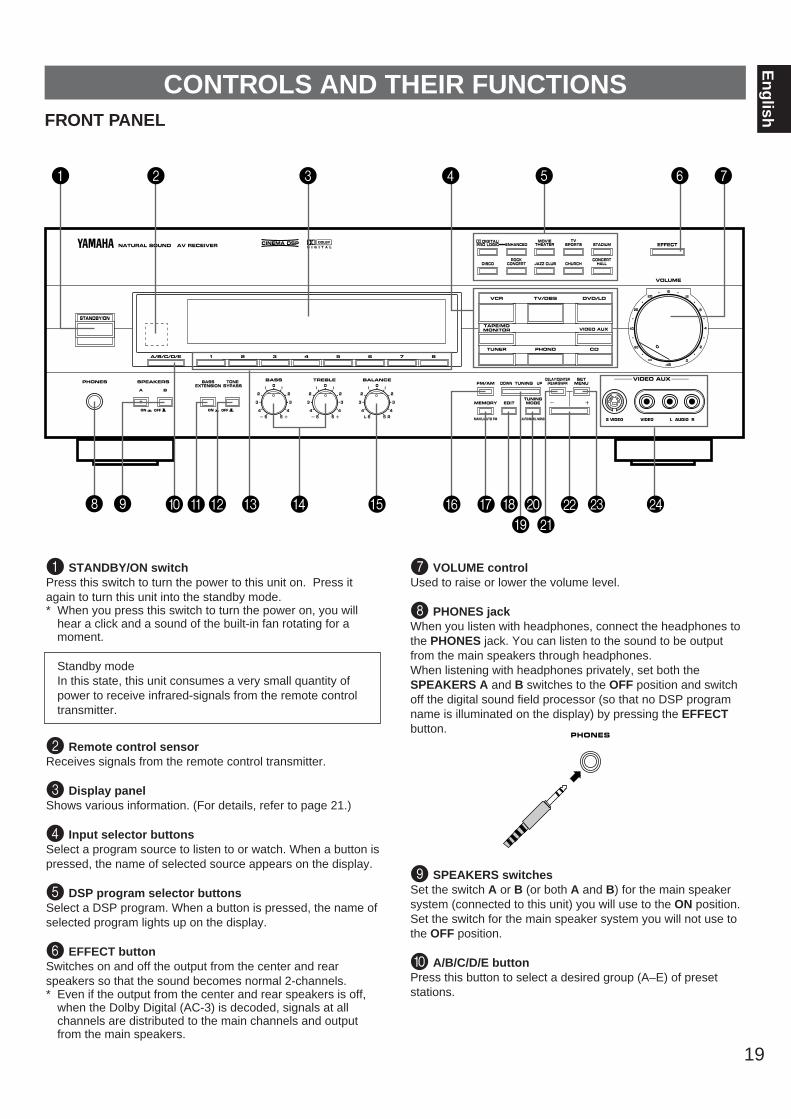
1 STANDBY/ON switchPress this switch to turn the power to this unit on. Press itagain to turn this unit into the standby mode.* When you press this switch to turn the power on, you will
hear a click and a sound of the built-in fan rotating for amoment.
Standby modeIn this state, this unit consumes a very small quantity ofpower to receive infrared-signals from the remote controltransmitter.
2 Remote control sensorReceives signals from the remote control transmitter.
3 Display panelShows various information. (For details, refer to page 21.)
4 Input selector buttonsSelect a program source to listen to or watch. When a button ispressed, the name of selected source appears on the display.
5 DSP program selector buttonsSelect a DSP program. When a button is pressed, the name ofselected program lights up on the display.
6 EFFECT buttonSwitches on and off the output from the center and rearspeakers so that the sound becomes normal 2-channels.* Even if the output from the center and rear speakers is off,
when the Dolby Digital (AC-3) is decoded, signals at allchannels are distributed to the main channels and outputfrom the main speakers.
7 VOLUME controlUsed to raise or lower the volume level.
8 PHONES jackWhen you listen with headphones, connect the headphones tothe PHONES jack. You can listen to the sound to be outputfrom the main speakers through headphones.When listening with headphones privately, set both theSPEAKERS A and B switches to the OFF position and switchoff the digital sound field processor (so that no DSP programname is illuminated on the display) by pressing the EFFECTbutton.
9 SPEAKERS switchesSet the switch A or B (or both A and B) for the main speakersystem (connected to this unit) you will use to the ON position.Set the switch for the main speaker system you will not use tothe OFF position.
0 A/B/C/D/E buttonPress this button to select a desired group (A–E) of presetstations.
PHONES

20
A BASS EXTENSION switchWhen this switch is pressed inward (ON), boosts bassfrequency response at the main left and main right channelswhile maintaining overall tonal balance. If you do not have asubwoofer, the use of this switch will be effective to reinforcethe bass frequencies.
B TONE BYPASS switchWhen this switch is pressed inward (ON), the input signal doesnot pass through the tone (BASS and TREBLE) controlcircuitry so that it is unaffected by the tone control circuitry. Usethis switch to obtain pure sound and to check the tone controlsetting. Press this switch to release it outward (OFF) to use thetone control circuitry.
C Preset station number selector buttonsSelect a preset station number (1 to 8).
D Tone controlsThese controls are effective only for the sound from the mainspeakers.BASSUsed to increase or decrease the low frequency response.The 0 position produces flat response.TREBLEUsed to increase or decrease the high frequency response.The 0 position produces flat response.
E BALANCE controlThis control is effective only for the sound from the mainspeakers.Adjusts the balance of the output volume to the left and rightspeakers to compensate for sound imbalance caused byspeaker location or listening room conditions.
F FM/AM buttonPress this button to switch the reception band to FM or AM.
G MEMORY (MAN’L/AUTO FM) buttonWhen this button is pressed, the “MEMORY” indicator flashesfor about 5 seconds. During this period, select a desiredpreset station number by pressing the corresponding presetstation number selector button to enter the displayed stationinto the memory.When this button is pressed and held for more than 3 seconds,the automatic preset tuning begins. (For details, refer to page34.)
H EDIT buttonThis button is used to exchange the places of two presetstations with each other.
I TUNING DOWN/UP buttonUsed for tuning. Press the “UP” side to tune in to higherfrequencies, and press the “DOWN” side to tune in to lowerfrequencies.
J TUNING MODE (AUTO/MAN’L MONO) buttonPress this button to switch the tuning mode to automatic ormanual. To select the automatic tuning mode, press thisbutton so that the “AUTO TUNING” indicator lights up on thedisplay. To select the manual tuning mode, press this buttonso that the “AUTO TUNING” indicator goes off.
K DELAY/CENTER/REAR/SWFR buttonWhenever pressed, selects the item of changing delay time(DELAY), center speaker output level (CENTER), rear speakeroutput level (REAR) and subwoofer output level (SWFR) inturn.* Depending on a mode of this unit, the number of selections
differs. For example, when the built-in digital sound fieldprocessor (including the Dolby Pro Logic Decoder or theDolby Digital (AC-3) Decoder) is off, only the item forchanging subwoofer output level can be selected.
L –/+ buttonAdjusts the level of item selected by pressing theDELAY/CENTER/REAR/SWFR button. Moreover, performssetting changes and adjustments for functions selected bypressing the SET MENU button.
M SET MENU buttonWhenever pressed, selects functions in the SET MENU mode.
N VIDEO AUX terminalsConnect an auxiliary video or audio input source unit such as acamcorder to these terminals. If the connected video unit has aS video output terminal, connect it to the S VIDEO terminal toobtain a high resolution picture. The source connected to theseterminals can be selected by the corresponding input selectorbutton.
21
En
glishDISPLAY PANEL
PRESET
kHzMHz
MEMORY
AMFM
SLEEPTAPE 2 MONITOR
DIGITAL
STEREO
0 20 l00 ROOM 2 CONTROL
NORMAL WIDE PHANTOMAUTO
40 60
SPEAKERS PCM DSP PRO LOGIC
AUTO TUNING A
SPEAKERS B
ROOM 2
70 mm ENHANCED dB
mS
DIGITALDIGITAL
1
32 4 5 6 7 8 9
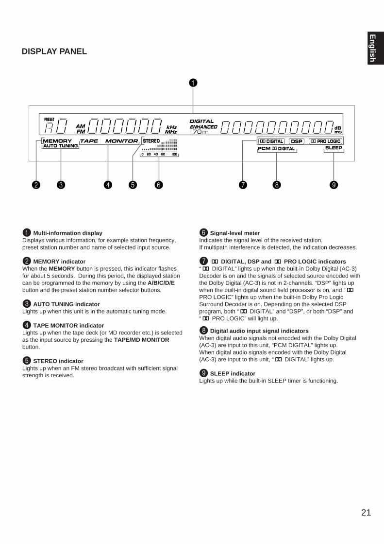
1 Multi-information displayDisplays various information, for example station frequency,preset station number and name of selected input source.
2 MEMORY indicatorWhen the MEMORY button is pressed, this indicator flashesfor about 5 seconds. During this period, the displayed stationcan be programmed to the memory by using the A/B/C/D/Ebutton and the preset station number selector buttons.
3 AUTO TUNING indicatorLights up when this unit is in the automatic tuning mode.
4 TAPE MONITOR indicatorLights up when the tape deck (or MD recorder etc.) is selectedas the input source by pressing the TAPE/MD MONITORbutton.
5 STEREO indicatorLights up when an FM stereo broadcast with sufficient signalstrength is received.
6 Signal-level meterIndicates the signal level of the received station.If multipath interference is detected, the indication decreases.
7 DIGITAL, DSP and PRO LOGIC indicators“ DIGITAL” lights up when the built-in Dolby Digital (AC-3)Decoder is on and the signals of selected source encoded withthe Dolby Digital (AC-3) is not in 2-channels. “DSP” lights upwhen the built-in digital sound field processor is on, and “PRO LOGIC” lights up when the built-in Dolby Pro LogicSurround Decoder is on. Depending on the selected DSPprogram, both “ DIGITAL” and “DSP”, or both “DSP” and“ PRO LOGIC” will light up.
8 Digital audio input signal indicatorsWhen digital audio signals not encoded with the Dolby Digital(AC-3) are input to this unit, “PCM DIGITAL” lights up.When digital audio signals encoded with the Dolby Digital (AC-3) are input to this unit, “ DIGITAL” lights up.
9 SLEEP indicatorLights up while the built-in SLEEP timer is functioning.

22
4. CENTER SPEAKERChoices: NRML/WIDE/PHNTMPreset position: NRML
NRML (Normal):Select this position when you use a center speakerthat is smaller than the main speakers. In thisposition, low bass signals (below 90 Hz) at the centerchannel are output from the main speakers (or theSUBWOOFER OUTPUT terminal if the SMALLposition is selected on “6. MAIN SPEAKER” and theSWFR position is selected on “7. LFE/BASS OUT”).
WIDE: Select this position when your center speaker isapproximately the same size as the main speakers.
PHNTM (Phantom):Select this position when you do not have a centerspeaker. The center channel sound will be outputfrom the left and right main speakers.
5. REAR SPEAKERChoices: SMALL/LARGEPreset position: SMALL
SMALL: Select this position if your rear speakers do not havea high ability for bass reproduction.In this position, low bass signals (below 90 Hz) at therear channels are output from the SUBWOOFEROUTPUT terminal (or the main speakers if the MAINposition is selected on “7. LFE/BASS OUT”).
LARGE: Select this position if your rear speakers have a highability for bass reproduction, or a subwoofer isconnected to the rear speaker in parallel.In this position, full range signals are output from therear speakers.
6. MAIN SPEAKERChoices: SMALL/LARGEPreset position: LARGE
SMALL: Select this position if your main speakers do not havea high ability for bass reproduction. However, if yoursystem does not include a subwoofer, do not selectthis position.In this position, low bass signals (below 90 Hz) at themain channels are output from the SUBWOOFEROUTPUT terminal (if the SWFR or BOTH position isselected on “7. LFE/BASS OUT”).
LARGE: Select this position if your main speakers have a highability for bass reproduction.In this position, full range signals present at the mainchannels are output from the main speakers.
7. LFE/BASS OUTChoices: MAIN/SWFR/BOTHPreset position: SWFR
MAIN: Select this position if your system does not include asubwoofer.In this position, full range signals present at the mainchannels, signals from the LFE channel and otherlow bass signals that are selected on “4. CENTERSPEAKER” to “6. MAIN SPEAKER” to be distributedfrom other channels are output from the mainspeakers.
SWFR/BOTH:Select either the SWFR or BOTH position if yoursystem includes a subwoofer.In either position, signals at LFE channel and otherlow bass signals that are selected on “4. CENTERSPEAKER” to “6. MAIN SPEAKER” to be distributedfrom other channels are output from theSUBWOOFER OUTPUT terminal.When the LARGE position is selected on “6. MAINSPEAKER”, in the SWFR position, no signal isdistributed from the main channels to theSUBWOOFER OUTPUT terminal, however in theBOTH position, low bass signals from the mainchannels are output to both of the main speakers andthe SUBWOOFER OUTPUT terminal.
SELECTING THE OUTPUT MODES SUITABLE FOR YOUR SPEAKERSYSTEMThis unit provides you the following four functions to determine the method of distributing output signals to speakers suitable foryour audio system. When speaker connections are all completed, select a proper position on each function to make the best use ofyour speaker system.
4. CENTER SPEAKER (CNTR)5. REAR SPEAKER (REAR)6. MAIN SPEAKER (MAIN)7. LFE/BASS OUT (BASS)
ADJUSTMENTS BEFORE USING THIS UNIT
DESCRIPTION OF EACH FUNCTION
23
En
glishMETHOD OF CHANGING SELECTIONS
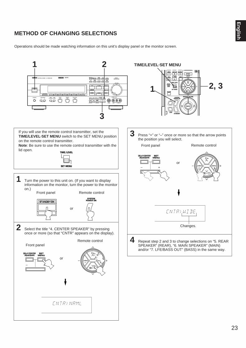
Operations should be made watching information on this unit’s display panel or the monitor screen.
If you will use the remote control transmitter, set theTIME/LEVEL·SET MENU switch to the SET MENU positionon the remote control transmitter.Note: Be sure to use the remote control transmitter with thelid open.
1 Turn the power to this unit on. (If you want to displayinformation on the monitor, turn the power to the monitoron.)
2 Select the title “4. CENTER SPEAKER” by pressingonce or more (so that “CNTR” appears on the display).
3 Press “+” or “–” once or more so that the arrow pointsthe position you will select.
4 Repeat step 2 and 3 to change selections on “5. REARSPEAKER” (REAR), “6. MAIN SPEAKER” (MAIN)and/or “7. LFE/BASS OUT” (BASS) in the same way.
Front panel
Front panel
or
Remote control
Front panel
or
Remote control
STANDBY/ON
DELAY/CENTER/REAR/SWFR
SETMENU
DELAY/CENTER/REAR/SWFR
SETMENU
TIME/LEVEL
SET MENU
NORMAL WIDE PHANTOMAUTO
NORMAL WIDE PHANTOMAUTO
DIGITAL/PRO LOGIC ENHANCED
MOVIETHEATER
TVSPORTS STADIUM
STANDBY/ON
NATURAL SOUND AV RECEIVER
SPEAKERSPHONES
A
ON OFF ON OFF
B
BASS TREBLE BALANCE VIDEO AUX
S VIDEO VIDEO L AUDIO R
VOLUME
5 54
3
2l 0 l
2
3
45 5
4
3
2l 0 l
2
3
4L R
l620
28
40
60
l2
8
4
2
0–dB
BASSEXTENSION
TONEBYPASS
CINEMA DSP
5 54
3
2l 0 l
2
3
4
DELAY/CENTER/REAR/SWFRFM/AM
MAN’L/AUTO FM
TUNINGMODE
AUTO/MAN’L MONO
SETMENU
DISCOCONCERT
HALLROCK
CONCERT
EFFECT
CHURCHJAZZ CLUB
DOWN TUNING UP
MEMORY EDIT
VCR DVD/LDTV/DBS
TAPE/MDMONITOR VIDEO AUX
TUNER CDPHONO
A/B/C/D/E 1 2 3 4 5 6 7 8
EFFECT
ON/OFF
ROCK JAZZ CLUB CHURCH
7 8 9
HALL
TIME/LEVEL
SET MENU
DELAYCENTERREARSWFR
TEST
SLEEP
MASTER VOLUME
TV
VCRSTANDBY
SYSTEMPOWER ON
0
+10
MUTE
1
1
3
2
2, 3
TIME/LEVEL·SET MENU
Remote control
or
SYSTEMPOWER ON
Changes.

24
1
Set to the “∞” position.
2 Turn the power on.
3 Select the main speakers to be used.
* If you use two main speaker systems, press both the Aand B switches.
4
Set to the “0” position.
5
Set to the “OFF ( )”.
6 Set the TIME/LEVEL·SET MENU switch on the remotecontrol transmitter to the TIME/LEVEL position.
7
This procedure lets you adjust the sound output level balance between the main, center, and rear speakers using the built-in testtone generator. When this adjustment is performed, the sound output level heard at the listening position will be the same fromeach speaker. This is important for the best performance of the digital sound field processor, the Dolby Digital (AC-3) decoder andthe Dolby Pro Logic Surround decoder.The adjustment of each speaker output level should be done at your listening position with the remote control transmitter.Otherwise, the result may not be satisfactory.Note: Be sure to use the remote control transmitter with the lid open.
SPEAKERS
A
ON OFF
B
BASS TREBLE
5 54
3
2l 0 l
2
3
45 5
4
3
2l 0 l
2
3
4
BALANCE
5 54
3
2l 0 l
2
3
4L R
l620
28
40
60
l2
8
4
2
0–dB
VOLUME
STANDBY/ON
12
3
DIGITAL/PRO LOGIC ENHANCED
MOVIETHEATER
TVSPORTS STADIUM
STANDBY/ON
NATURAL SOUND AV RECEIVER
SPEAKERSPHONES
A
ON OFF ON OFF
B
BASS TREBLE BALANCE VIDEO AUX
S VIDEO VIDEO L AUDIO R
VOLUME
5 54
3
2l 0 l
2
3
45 5
4
3
2l 0 l
2
3
4L R
l620
28
40
60
l2
8
4
2
0–dB
BASSEXTENSION
TONEBYPASS
CINEMA DSP
5 54
3
2l 0 l
2
3
4
DELAY/CENTER/REAR/SWFRFM/AM
MAN’L/AUTO FM
TUNINGMODE
AUTO/MAN’L MONO
SETMENU
DISCOCONCERT
HALLROCK
CONCERT
EFFECT
CHURCHJAZZ CLUB
DOWN TUNING UP
MEMORY EDIT
VCR DVD/LDTV/DBS
TAPE/MDMONITOR VIDEO AUX
TUNER CDPHONO
A/B/C/D/E 1 2 3 4 5 6 7 8
ON OFF
BASSEXTENSION
TONEBYPASS
5 4 4, 9
V-AUX
PHONO
EFFECT
ON/OFF
PRESET A/B/C/D/E
DIGITAL/PRO LOGIC ENHANCED
MOVIETHEATER
1 2 3
SPORTS STADIUM DISCOTV
4 5 6
ROCK JAZZ CLUB CHURCH
7 8 9
HALL
TIME/LEVEL
SET MENU
DELAYCENTERREARSWFR
TEST
SLEEP
MASTER VOLUME
TV
VCRSTANDBY
SYSTEMPOWER ON
0
+10
MUTE
6
8
10
7, 11
SPEAKER BALANCE ADJUSTMENT
TEST
TIME/LEVEL
SET MENU
Front panel
Front panel
Front panel
Front panel
Front panel
Remote control
Remote control
2
Remote control
SYSTEMPOWER ON
or
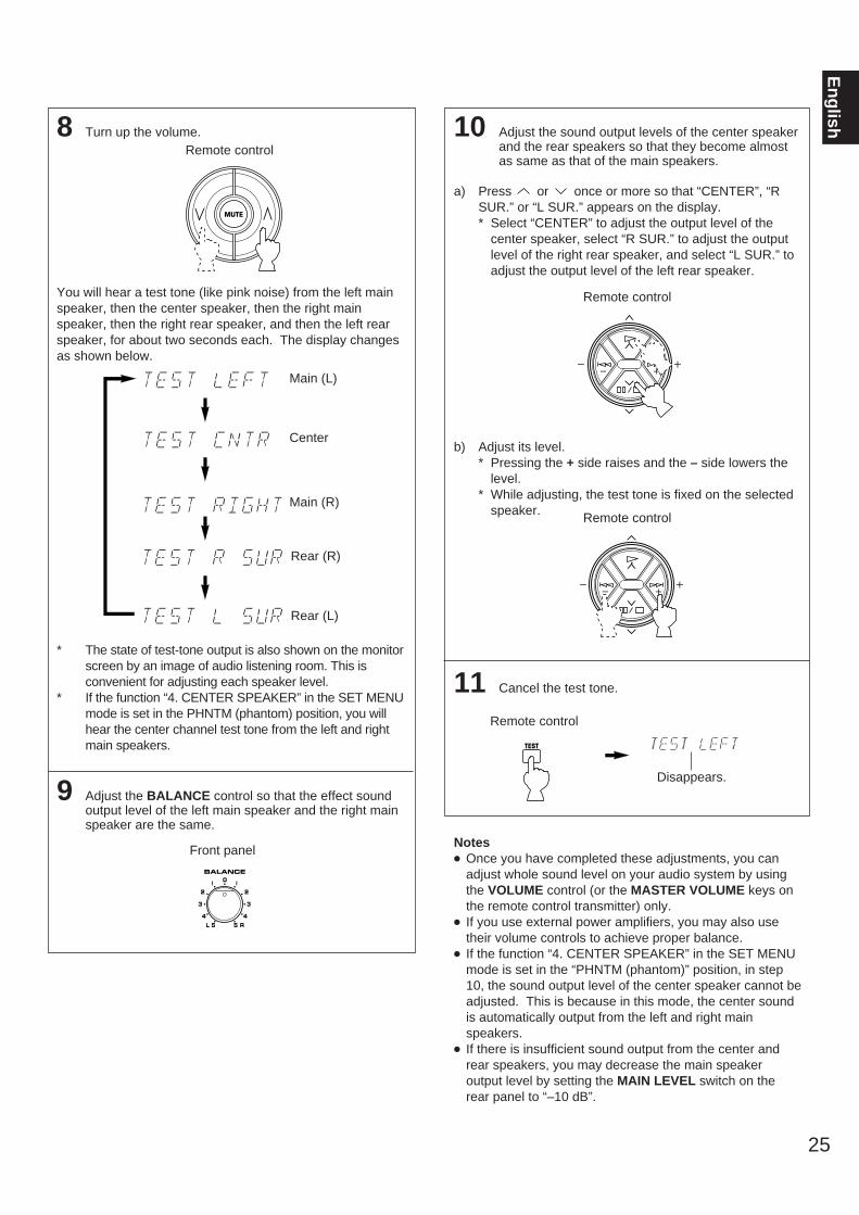
8 Turn up the volume.
You will hear a test tone (like pink noise) from the left mainspeaker, then the center speaker, then the right mainspeaker, then the right rear speaker, and then the left rearspeaker, for about two seconds each. The display changesas shown below.
* The state of test-tone output is also shown on the monitorscreen by an image of audio listening room. This isconvenient for adjusting each speaker level.
* If the function “4. CENTER SPEAKER” in the SET MENUmode is set in the PHNTM (phantom) position, you willhear the center channel test tone from the left and rightmain speakers.
9 Adjust the BALANCE control so that the effect soundoutput level of the left main speaker and the right mainspeaker are the same.
10 Adjust the sound output levels of the center speakerand the rear speakers so that they become almostas same as that of the main speakers.
a) Press or once or more so that “CENTER”, “RSUR.” or “L SUR.” appears on the display.* Select “CENTER” to adjust the output level of the
center speaker, select “R SUR.” to adjust the outputlevel of the right rear speaker, and select “L SUR.” toadjust the output level of the left rear speaker.
b) Adjust its level.* Pressing the + side raises and the – side lowers the
level.* While adjusting, the test tone is fixed on the selected
speaker.
11 Cancel the test tone.
Notes Once you have completed these adjustments, you can
adjust whole sound level on your audio system by usingthe VOLUME control (or the MASTER VOLUME keys onthe remote control transmitter) only.
If you use external power amplifiers, you may also usetheir volume controls to achieve proper balance.
If the function “4. CENTER SPEAKER” in the SET MENUmode is set in the “PHNTM (phantom)” position, in step10, the sound output level of the center speaker cannot beadjusted. This is because in this mode, the center soundis automatically output from the left and right mainspeakers.
If there is insufficient sound output from the center andrear speakers, you may decrease the main speakeroutput level by setting the MAIN LEVEL switch on therear panel to “–10 dB”.
25
En
glish
MUTE
BALANCE
5 54
3
2l 0 l
2
3
4L R
Main (L)
Main (R)
Center
Rear (L)
Rear (R)
Disappears.
TEST
Remote control
Front panel
Remote control
Remote control
Remote control

Operations should be made watching information on this unit’sdisplay panel or the monitor screen. If you want to displayinformation on the monitor, turn the power to the monitor on.
If you will use the remote control transmitter, set theTIME/LEVEL·SET MENU switch to the SET MENU positionon the remote control transmitter.Note: Be sure to use the remote control transmitter with thelid open.
1 Press once or more until the title of function on which youwill make a change appears on the display.
2 Select any desired position or edit parameters on thefunction.
3 Repeat step 1 and 2 to make a setting change oradjustment on any other function.
26
ADJUSTMENTS IN THE “SET MENU” MODE
1. CENTER DELAY (C. DELAY)2. DYNAMIC RANGE (D. RNG)3. LFE LEVEL (LFE)4. CENTER SPEAKER (CNTR)
5. REAR SPEAKER (REAR)6. MAIN SPEAKER (MAIN)7. LFE/BASS OUT (BASS)8. TV/DBS INPUT (INPUT)
Front panel
or
Remote control
Front panel
or
Remote control
DELAY/CENTER/REAR/SWFR
SETMENU
DELAY/CENTER/REAR/SWFR
SETMENU
TIME/LEVEL
SET MENU
METHOD OF SETTING CHANGE AND ADJUSTMENT
The following eight types of functions maximize the performance of your system and expand your enjoyment for audio listening and videowatching.
DIGITAL/PRO LOGIC ENHANCED
MOVIETHEATER
TVSPORTS STADIUM
STANDBY/ON
NATURAL SOUND AV RECEIVER
SPEAKERSPHONES
A
ON OFF ON OFF
B
BASS TREBLE BALANCE VIDEO AUX
S VIDEO VIDEO L AUDIO R
VOLUME
5 54
3
2l 0 l
2
3
45 5
4
3
2l 0 l
2
3
4L R
l620
28
40
60
l2
8
4
2
0–dB
BASSEXTENSION
TONEBYPASS
CINEMA DSP
5 54
3
2l 0 l
2
3
4
DELAY/CENTER/REAR/SWFRFM/AM
MAN’L/AUTO FM
TUNINGMODE
AUTO/MAN’L MONO
SETMENU
DISCOCONCERT
HALLROCK
CONCERT
EFFECT
CHURCHJAZZ CLUB
DOWN TUNING UP
MEMORY EDIT
VCR DVD/LDTV/DBS
TAPE/MDMONITOR VIDEO AUX
TUNER CDPHONO
A/B/C/D/E 1 2 3 4 5 6 7 8
EFFECT
ON/OFF
ROCK JAZZ CLUB CHURCH
7 8 9
HALL
TIME/LEVEL
SET MENU
DELAYCENTERREARSWFR
TEST
SLEEP
MASTER VOLUME
TV
VCRSTANDBY
SYSTEMPOWER ON
0
+10
MUTE
2
1
1, 2
TIME/LEVEL·SET MENU

27
En
glishDESCRIPTIONS OF THE FUNCTIONS
1. CENTER DELAY (Adjusting the delayof center sounds (dialog etc.))
Control range: 0 ms to 5 ms (in 1 ms step)Preset value: 0 ms
* This adjustment is effective only when the Dolby Digital(AC-3) is decoded and the signals of selected sourceencoded with the Dolby Digital (AC-3) contain center-channel signals.
Adjusts the delay between the main sounds (at the mainchannels) and dialog etc. (at the center channel).The larger the value, the later the dialog etc. is generated.
This is for making sounds from the left main, center and rightmain speakers reach your listening position at the same timeby delaying the sound from the center speaker if the distancefrom the center speaker to your listening position is shorterthan the distance from the left or right main speaker to yourlistening position.
2. DYNAMIC RANGE (Adjusting dynamicrange)
Choices: MAX/STD/MINPreset position: MAX
* This adjustment is effective only when the Dolby Digital(AC-3) is decoded.
MAX: “Dynamic range” is the difference between themaximum level and the minimum level of sounds.Sounds on a movie originally designed for movietheaters feature very wide dynamic range.Dolby Digital (AC-3) technology can bring the originalsound track into a home audio format with this widedynamic range unchanged.In this position, a source encoded with the DolbyDigital (AC-3) is reproduced in the original soundtrack’s wide dynamic range providing you withpowerful sounds like a movie theater.Selecting this position will be more ideal if you canlisten to a source in a high output level in a roomspecially soundproofed for audio/video enjoyment.
STD (Standard):Powerful sounds of extremely wide dynamic rangeare not always suitable for home use. Dependingupon the condition of your listening environment, itmay not be possible to increase the sound outputlevel as high as a movie theater. However, in a levelsuitable for listening to in your room, the low levelparts of source sound cannot be heard well becausethey will be lost among noises in your environment.
Dolby Digital (AC-3) technology also made itpossible to reduce an original sound track’s dynamicrange for a home audio format by “compressing” thedata of sound.In this position, a source encoded with the DolbyDigital (AC-3) is reproduced in the “compressed”dynamic range of the source suitable for low levellistening.
MIN: In this position, dynamic range is more reduced thanin the STD position. Selecting this position will beeffective when you must listen to a source inextremely low level.
3. LFE LEVEL (Adjusting the outputlevel at the LFE (low frequency effect)channel)
Control range: –14 dB to 0 dB (in 2 dB step)Preset value: 0 dB
* This adjustment is effective only when the Dolby Digital (AC-3) is decoded and the signals of selected source encodedwith the Dolby Digital (AC-3) contain LFE signals.
Adjusts the output level at the LFE (low frequency effect)channel. If the LFE signals are mixed with signals at otherchannels to output them from the same speakers, the ratio ofLFE signal level to the level of other signals are adjusted. (Seepage 6 for details about the LFE channel.)
4. CENTER SPEAKER5. REAR SPEAKER6. MAIN SPEAKER7. LFE/BASS OUT
See pages 22 to 23 for details. (Once you have selectedproper modes, you do not have to make a setting change untilany alteration is made in your speaker system.)
8. TV/DBS INPUT (Selecting the initialinput mode of the sources connectedto the TV/DBS input terminals)
For the sources connected to the TV/DBS input terminals ofthis unit only, you can designate the input mode that isautomatically selected when the power of this unit is switchedon.
AUTO: In this position, the AUTO input mode is alwaysselected when the power of this unit is switched on.
LAST: In this position, the input mode you have selectedlast time is memorized and will not be changed evenif the power of this unit is switched on.
* See page 29 for details about switching the input mode.

28
1
Set to the “∞” position.
2 Turn the power on.
3 Select the desired input source by using the inputselector buttons.(For video sources, turn the TV/monitor ON.)
* The name of the selected input source will appear on thedisplay.
4 For the DVD/LD or TV/DBS source, its current inputmode is also shown.* To change the input mode for the DVD/LD or TV/DBS
source, press the input selector button for the currentlyselected source once or more until the desired inputmode (AUTO or ANALOG) is shown on the displaypanel. (See page 29 for details on switching the inputmode.)
5 Select the main speakers to be used.
* If you use two main speaker systems, press both the Aand B switches.
BASIC OPERATIONSTO PLAY A SOURCE
l620
28
40
60
l2
8
4
2
0–dB
VOLUME
SPEAKERS
A
ON OFF
B
STANDBY/ON
1, 72
5 8
DIGITAL/PRO LOGIC ENHANCED
MOVIETHEATER
TVSPORTS STADIUM
STANDBY/ON
NATURAL SOUND AV RECEIVER
SPEAKERSPHONES
A
ON OFF ON OFF
B
BASS TREBLE BALANCE VIDEO AUX
S VIDEO VIDEO L AUDIO R
VOLUME
5 54
3
2l 0 l
2
3
45 5
4
3
2l 0 l
2
3
4L R
l620
28
40
60
l2
8
4
2
0–dB
BASSEXTENSION
TONEBYPASS
CINEMA DSP
5 54
3
2l 0 l
2
3
4
DELAY/CENTER/REAR/SWFRFM/AM
MAN’L/AUTO FM
TUNINGMODE
AUTO/MAN’L MONO
SETMENU
DISCOCONCERT
HALLROCK
CONCERT
EFFECT
CHURCHJAZZ CLUB
DOWN TUNING UP
MEMORY EDIT
VCR DVD/LDTV/DBS
TAPE/MDMONITOR VIDEO AUX
TUNER CDPHONO
A/B/C/D/E 1 2 3 4 5 6 7 8
3, 43, 4
7Note: If you will use the remote control transmitter, be sure to use it with the lid open.
Front panel
or
Remote control
DVD/LDTV/DBS
VIDEO AUX
DVD/LD
ROOM 2 CONTROL
NORMAL WIDE PHANTOMAUTO SPEAKERS
DSP
A SPEAKERS B
Front panel
or
Remote control
Input mode
DVD/LDTV/DBS
VIDEO AUX
DVD/LD
ROOM 2 CONTROL
NORMAL WIDE PHANTOMAUTO SPEAKERS
DSP
A SPEAKERS B
TAPE
A/BREC/PAUSE
BA
ACD
TUNER
VCR
BDVD/LD
V-AUX
PHONO
EFFECT
ON/OFF
TV/DBS
C
DIR
DISCSTOP
PRESET A/B/C/D/E
DIGITAL/PRO LOGIC ENHANCED
MOVIETHEATER
1 2 3
SPORTS STADIUM DISCOTV
4 5 6
ROCK JAZZ CLUB CHURCH
7 8 9
HALL
TIME/LEVEL
SET MENU
DELAYCENTERREARSWFR
TEST
SLEEP
MASTER VOLUME
TV
VCRSTANDBY
SYSTEMPOWER ON
0
+10
MUTE
Front panel
Front panel
Front panel
2
Remote controlSYSTEM
POWER ON
or
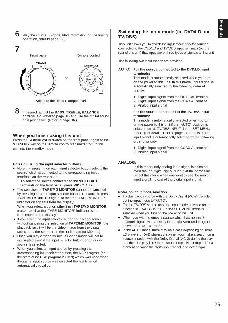
6 Play the source. (For detailed information on the tuningoperation, refer to page 32.)
7
Adjust to the desired output level.
8 If desired, adjust the BASS, TREBLE, BALANCEcontrols, etc. (refer to page 31) and use the digital soundfield processor. (Refer to page 36.)
When you finish using this unitPress the STANDBY/ON switch on the front panel again or theSTANDBY key on the remote control transmitter to turn thisunit into the standby mode.
Notes on using the input selector buttons Note that pressing on each input selector button selects the
source which is connected to the corresponding inputterminals on the rear panel.* To select the source connected to the VIDEO AUX
terminals on the front panel, press VIDEO AUX. The selection of TAPE/MD MONITOR cannot be canceled
by pressing another input selector button. To cancel it, pressTAPE/MD MONITOR again so that the “TAPE MONITOR”indicator disappears from the display.When you select a button other than TAPE/MD MONITOR,make sure that the “TAPE MONITOR” indicator is notilluminated on the display.
If you select the input selector button for a video sourcewithout canceling the selection of TAPE/MD MONITOR, theplayback result will be the video image from the videosource and the sound from the audio tape (or MD etc.).
Once you play a video source, its video image will not beinterrupted even if the input selector button for an audiosource is selected.
When you select an input source by pressing thecorresponding input selector button, the DSP program (orthe state of no DSP program is used) which was used whenthe same input source was selected the last time willautomatically recalled.
Switching the input mode (for DVD/LD andTV/DBS)
This unit allows you to switch the input mode only for sourcesconnected to the DVD/LD and TV/DBS input terminals (on therear of this unit) that input two or three types of signals to this unit.
The following two input modes are provided.
AUTO: For the source connected to the DVD/LD inputterminals:This mode is automatically selected when you turnon the power to this unit. In this mode, input signal isautomatically selected by the following order ofpriority.
1. Digital input signal from the OPTICAL terminal2. Digital input signal from the COAXIAL terminal3. Analog input signal
For the source connected to the TV/DBS inputterminals:This mode is automatically selected when you turnon the power to this unit if the “AUTO” position isselected on “8. TV/DBS INPUT” in the SET MENUmode. (For details, refer to page 27.) In this mode,input signal is automatically selected by the followingorder of priority.
1. Digital input signal from the COAXIAL terminal2. Analog input signal
ANALOG:In this mode, only analog input signal is selectedeven though digital signal is input at the same time.Select this mode when you want to use the analoginput signal instead of the digital input signal.
Notes on input mode selection To play back a source with the Dolby Digital (AC-3) decoded,
set the input mode to “AUTO”. For the TV/DBS source only, the input mode selected on the
function “8. TV/DBS INPUT” in the SET MENU mode isselected when you turn on the power of this unit.
When you want to enjoy a source which has normal 2-channel signals with a Dolby Pro Logic Surround program,select the ANALOG mode.
In the AUTO mode, there may be a case depending on someLD players or DVD players that when you make a search on asource encoded with the Dolby Digital (AC-3) during the playand then the play is restored, sound output is interrupted for amoment because the digital input signal is selected again.
29
En
glish
Front panel
or
Remote control
l620
28
40
60
l2
8
4
2
0–dB
VOLUME
MASTER VOLUME
MUTE
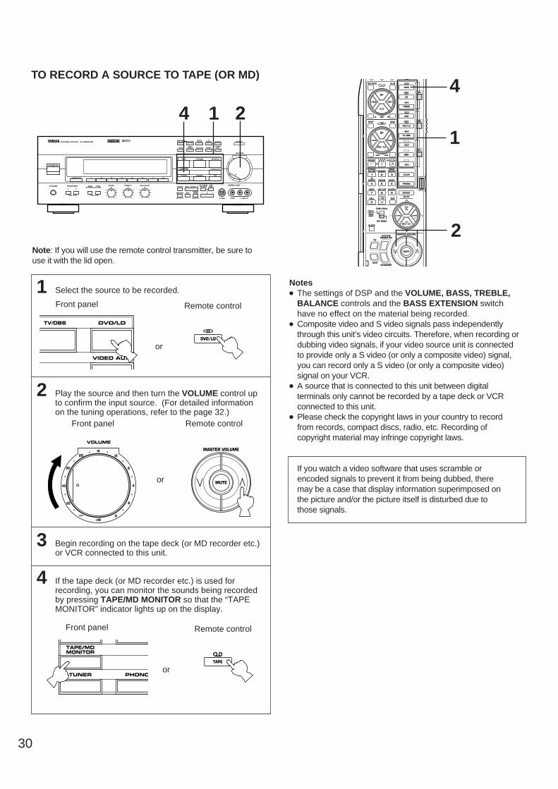
30
1 Select the source to be recorded.
2 Play the source and then turn the VOLUME control upto confirm the input source. (For detailed informationon the tuning operations, refer to the page 32.)
3 Begin recording on the tape deck (or MD recorder etc.)or VCR connected to this unit.
4 If the tape deck (or MD recorder etc.) is used forrecording, you can monitor the sounds being recordedby pressing TAPE/MD MONITOR so that the “TAPEMONITOR” indicator lights up on the display.
Notes The settings of DSP and the VOLUME, BASS, TREBLE,
BALANCE controls and the BASS EXTENSION switchhave no effect on the material being recorded.
Composite video and S video signals pass independentlythrough this unit’s video circuits. Therefore, when recording ordubbing video signals, if your video source unit is connectedto provide only a S video (or only a composite video) signal,you can record only a S video (or only a composite video)signal on your VCR.
A source that is connected to this unit between digitalterminals only cannot be recorded by a tape deck or VCRconnected to this unit.
Please check the copyright laws in your country to recordfrom records, compact discs, radio, etc. Recording ofcopyright material may infringe copyright laws.
If you watch a video software that uses scramble orencoded signals to prevent it from being dubbed, theremay be a case that display information superimposed onthe picture and/or the picture itself is disturbed due tothose signals.
TO RECORD A SOURCE TO TAPE (OR MD)
2 DIGITAL/PRO LOGIC ENHANCED
MOVIETHEATER
TVSPORTS STADIUM
STANDBY/ON
NATURAL SOUND AV RECEIVER
SPEAKERSPHONES
A
ON OFF ON OFF
B
BASS TREBLE BALANCE VIDEO AUX
S VIDEO VIDEO L AUDIO R
VOLUME
5 54
3
2l 0 l
2
3
45 5
4
3
2l 0 l
2
3
4L R
l620
28
40
60
l2
8
4
2
0–dB
BASSEXTENSION
TONEBYPASS
CINEMA DSP
5 54
3
2l 0 l
2
3
4
DELAY/CENTER/REAR/SWFRFM/AM
MAN’L/AUTO FM
TUNINGMODE
AUTO/MAN’L MONO
SETMENU
DISCOCONCERT
HALLROCK
CONCERT
EFFECT
CHURCHJAZZ CLUB
DOWN TUNING UP
MEMORY EDIT
VCR DVD/LDTV/DBS
TAPE/MDMONITOR VIDEO AUX
TUNER CDPHONO
A/B/C/D/E 1 2 3 4 5 6 7 8
14
DVD/LDTV/DBS
VIDEO AUX
Note: If you will use the remote control transmitter, be sure touse it with the lid open.
Front panel
or
Remote control
DVD/LD
Front panel
or
Remote control
TAPE/MDMONITOR
TUNER PHONO
TAPE
1
4
2
TAPE
A/BREC/PAUSE
BA
ACD
TUNER
VCR
BDVD/LD
V-AUX
PHONO
EFFECT
ON/OFF
TV/DBS
C
DIR
DISCSTOP
PRESET A/B/C/D/E
DIGITAL/PRO LOGIC ENHANCED
MOVIETHEATER
1 2 3
SPORTS STADIUM DISCOTV
4 5 6
ROCK JAZZ CLUB CHURCH
7 8 9
HALL
TIME/LEVEL
SET MENU
DELAYCENTERREARSWFR
TEST
SLEEP
MASTER VOLUME
TV
VCRSTANDBY
SYSTEMPOWER ON
0
+10
MUTE
Front panel
or
Remote control
l620
28
40
60
l2
8
4
2
0–dB
VOLUME
MASTER VOLUME
MUTE
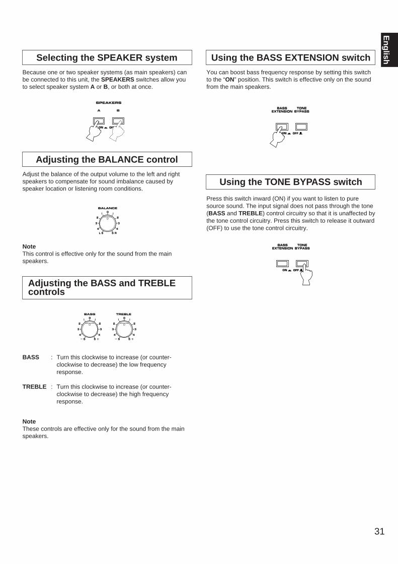
Selecting the SPEAKER systemBecause one or two speaker systems (as main speakers) canbe connected to this unit, the SPEAKERS switches allow youto select speaker system A or B, or both at once.
Adjusting the BALANCE controlAdjust the balance of the output volume to the left and rightspeakers to compensate for sound imbalance caused byspeaker location or listening room conditions.
NoteThis control is effective only for the sound from the mainspeakers.
Adjusting the BASS and TREBLEcontrols
BASS : Turn this clockwise to increase (or counter-clockwise to decrease) the low frequency response.
TREBLE : Turn this clockwise to increase (or counter-clockwise to decrease) the high frequency response.
NoteThese controls are effective only for the sound from the mainspeakers.
Using the BASS EXTENSION switchYou can boost bass frequency response by setting this switchto the “ON” position. This switch is effective only on the soundfrom the main speakers.
Using the TONE BYPASS switch
Press this switch inward (ON) if you want to listen to puresource sound. The input signal does not pass through the tone(BASS and TREBLE) control circuitry so that it is unaffected bythe tone control circuitry. Press this switch to release it outward(OFF) to use the tone control circuitry.
31
En
glish
SPEAKERS
A
ON OFF
B
BALANCE
5 54
3
2l 0 l
2
3
4L R
BASS TREBLE
5 54
3
2l 0 l
2
3
45 5
4
3
2l 0 l
2
3
4
ON OFF
BASSEXTENSION
TONEBYPASS
ON OFF
BASSEXTENSION
TONEBYPASS
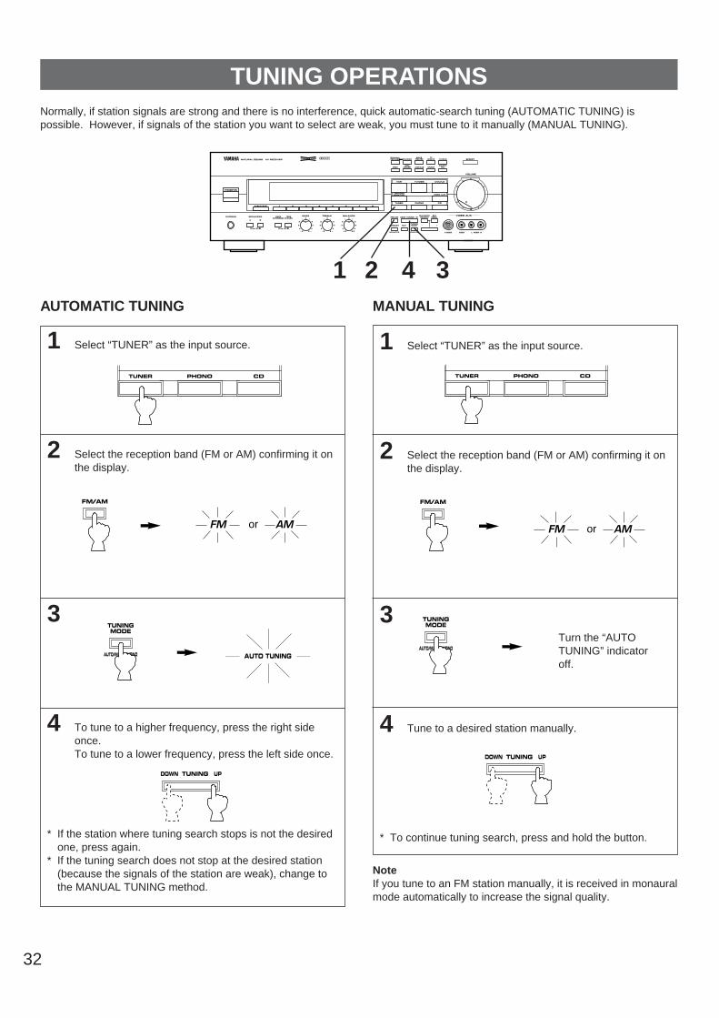
32
1 Select “TUNER” as the input source.
2 Select the reception band (FM or AM) confirming it onthe display.
3
4 Tune to a desired station manually.
* To continue tuning search, press and hold the button.
1 Select “TUNER” as the input source.
2 Select the reception band (FM or AM) confirming it onthe display.
3
4 To tune to a higher frequency, press the right sideonce.To tune to a lower frequency, press the left side once.
* If the station where tuning search stops is not the desiredone, press again.
* If the tuning search does not stop at the desired station(because the signals of the station are weak), change tothe MANUAL TUNING method.
TUNING OPERATIONSNormally, if station signals are strong and there is no interference, quick automatic-search tuning (AUTOMATIC TUNING) ispossible. However, if signals of the station you want to select are weak, you must tune to it manually (MANUAL TUNING).
NoteIf you tune to an FM station manually, it is received in monauralmode automatically to increase the signal quality.
AUTOMATIC TUNING MANUAL TUNING
FM/AM
TUNINGMODE
AUTO/MAN’L MONO
TUNINGMODE
AUTO/MAN’L MONO
DOWN TUNING UP
DOWN TUNING UP
AUTO TUNING
Turn the “AUTOTUNING” indicatoroff.
FM AMor
1
DIGITAL/PRO LOGIC ENHANCED
MOVIETHEATER
TVSPORTS STADIUM
STANDBY/ON
NATURAL SOUND AV RECEIVER
SPEAKERSPHONES
A
ON OFF ON OFF
B
BASS TREBLE BALANCE VIDEO AUX
S VIDEO VIDEO L AUDIO R
VOLUME
5 54
3
2l 0 l
2
3
45 5
4
3
2l 0 l
2
3
4L R
l620
28
40
60
l2
8
4
2
0–dB
BASSEXTENSION
TONEBYPASS
CINEMA DSP
5 54
3
2l 0 l
2
3
4
DELAY/CENTER/REAR/SWFRFM/AM
MAN’L/AUTO FM
TUNINGMODE
AUTO/MAN’L MONO
SETMENU
DISCOCONCERT
HALLROCK
CONCERT
EFFECT
CHURCHJAZZ CLUB
DOWN TUNING UP
MEMORY EDIT
VCR DVD/LDTV/DBS
TAPE/MDMONITOR VIDEO AUX
TUNER CDPHONO
A/B/C/D/E 1 2 3 4 5 6 7 8
2 34
FM/AM
FM AMor
TUNER CDPHONO TUNER CDPHONO
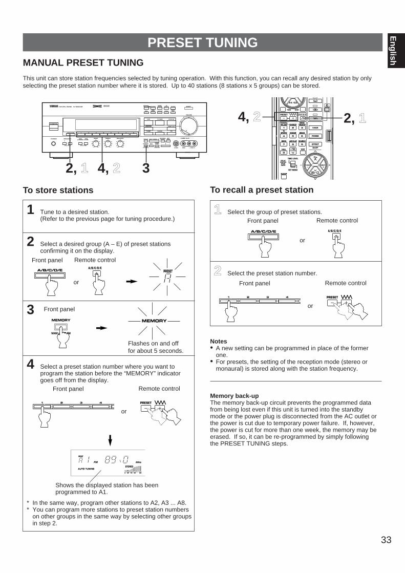
33
En
glish
1 Tune to a desired station.(Refer to the previous page for tuning procedure.)
2 Select a desired group (A – E) of preset stationsconfirming it on the display.
3
4 Select a preset station number where you want toprogram the station before the “MEMORY” indicatorgoes off from the display.
* In the same way, program other stations to A2, A3 ... A8.* You can program more stations to preset station numbers
on other groups in the same way by selecting other groupsin step 2.
11 Select the group of preset stations.
22 Select the preset station number.
Notes• A new setting can be programmed in place of the former
one.• For presets, the setting of the reception mode (stereo or
monaural) is stored along with the station frequency.
Memory back-upThe memory back-up circuit prevents the programmed datafrom being lost even if this unit is turned into the standbymode or the power plug is disconnected from the AC outlet orthe power is cut due to temporary power failure. If, however,the power is cut for more than one week, the memory may beerased. If so, it can be re-programmed by simply followingthe PRESET TUNING steps.
MANUAL PRESET TUNING
This unit can store station frequencies selected by tuning operation. With this function, you can recall any desired station by onlyselecting the preset station number where it is stored. Up to 40 stations (8 stations x 5 groups) can be stored.
PRESET TUNING
To store stations To recall a preset station
2, 11 34, 22
MAN’L/AUTO FM
MEMORY MEMORY
A/B/C/D/E PRESET
A/B/C/D/E
Flashes on and offfor about 5 seconds.
PRESET
MHzFMSTEREO
0 20 l00 ROOM 2 CONTROL 40 60
SPEAKERS AUTO TUNING A
SPEAKERS B
ROOM 2
Shows the displayed station has been programmed to A1.
DIGITAL/PRO LOGIC ENHANCED
MOVIETHEATER
TVSPORTS STADIUM
STANDBY/ON
NATURAL SOUND AV RECEIVER
SPEAKERSPHONES
A
ON OFF ON OFF
B
BASS TREBLE BALANCE VIDEO AUX
S VIDEO VIDEO L AUDIO R
VOLUME
5 54
3
2l 0 l
2
3
45 5
4
3
2l 0 l
2
3
4L R
l620
28
40
60
l2
8
4
2
0–dB
BASSEXTENSION
TONEBYPASS
CINEMA DSP
5 54
3
2l 0 l
2
3
4
DELAY/CENTER/REAR/SWFRFM/AM
MAN’L/AUTO FM
TUNINGMODE
AUTO/MAN’L MONO
SETMENU
DISCOCONCERT
HALLROCK
CONCERT
EFFECT
CHURCHJAZZ CLUB
DOWN TUNING UP
MEMORY EDIT
VCR DVD/LDTV/DBS
TAPE/MDMONITOR VIDEO AUX
TUNER CDPHONO
A/B/C/D/E 1 2 3 4 5 6 7 8
1 2 3 4
A/B/C/D/E
A/B/C/D/E
PRESET
V-AUX
PHONO
EFFECT
ON/OFF
C
PRESET A/B/C/D/E
DIGITAL/PRO LOGIC ENHANCED
MOVIETHEATER
1 2 3
SPORTS STADIUM DISCOTV
4 5 6
ROCK JAZZ CLUB CHURCH
7 8 9
HALL
TIME/LEVEL
SET MENU
DELAYCENTERREARSWFR
TEST
SLEEP
0
+10
Front panel Remote control
Front panel Remote control
Front panel
or
Front panel
Remote control
or
or
1 2 3 4 PRESET
Front panel Remote control
or
2, 114, 22

34
1
2
3
To tune to higher frequencies, press right side once.To tune to lower frequencies, press left side once.* If the TUNING button is not pressed, in a while, the
automatic preset tuning begins automatically toward higherfrequencies.
The automatic preset tuning begins from the frequencycurrently displayed. Received stations are programmed toA1, A2 ... A8 sequentially.* If more than 8 stations are received, they are also
programmed to the preset station numbers on other groups (B, C, D and E) in that order.
If you want to store the first station received by theautomatic preset tuning to a desired preset stationnumber.If, for example, you want to store the first received station toC5, select “C5” by using the A/B/C/D/E button and the presetstation number selector buttons after pressing the MEMORYbutton in step 2. Then press the TUNING button. The firstreceived station is stored to C5, and next stations to C6, C7 ...sequentially.If stations are stored up to E8, the automatic preset tuning isfinished automatically.
When the automatic preset tuning is finishedThe display shows the frequency of the last preset station.Check the contents and the number of preset stations byfollowing the procedure of the section “To recall a presetstation” on page 33.
To recall a preset stationSimply follow the procedure of the section “To recall a presetstation” on page 33.
Notes You can replace a preset station by another FM or AM
station manually by simply following the procedure of thesection “To store stations” on page 33.
If the number of received stations is not enough to be storedup to E8, the search is finished automatically after searchingall frequencies.
With this function, only FM stations with sufficient signalstrength are stored automatically. If the station you want toprogram is weak in signal strength, tune to it in monauralmanually and program it by following the procedure of thesection “To store stations” on page 33.
AUTOMATIC PRESET TUNINGYou can also make use of an automatic preset tuning function for FM stations only. By this function, this unit performs automatictuning and stores FM stations with strong signals sequentially. Up to 40 stations are stored automatically in the same way as in themanual preset tuning method on page 33.
To store stations
Press and hold formore than 3 seconds.
FM/AM
MAN’L/AUTO FM
MEMORY
DIGITAL/PRO LOGIC ENHANCED
MOVIETHEATER
TVSPORTS STADIUM
STANDBY/ON
NATURAL SOUND AV RECEIVER
SPEAKERSPHONES
A
ON OFF ON OFF
B
BASS TREBLE BALANCE VIDEO AUX
S VIDEO VIDEO L AUDIO R
VOLUME
5 54
3
2l 0 l
2
3
45 5
4
3
2l 0 l
2
3
4L R
l620
28
40
60
l2
8
4
2
0–dB
BASSEXTENSION
TONEBYPASS
CINEMA DSP
5 54
3
2l 0 l
2
3
4
DELAY/CENTER/REAR/SWFRFM/AM
MAN’L/AUTO FM
TUNINGMODE
AUTO/MAN’L MONO
SETMENU
DISCOCONCERT
HALLROCK
CONCERT
EFFECT
CHURCHJAZZ CLUB
DOWN TUNING UP
MEMORY EDIT
VCR DVD/LDTV/DBS
TAPE/MDMONITOR VIDEO AUX
TUNER CDPHONO
A/B/C/D/E 1 2 3 4 5 6 7 8
1 32
Flashes.
DOWN TUNING UP
FM
PRESET
MEMORYAUTO TUNING

35
En
glishEXCHANGING PRESET STATIONS
You can exchange the places of two preset stations with each other as shown below.
Example)If you want to shift the preset station on E1 to A5, and viceversa.
1 Recall the preset station on E1 (by following the methodof “To recall a preset station” on page 33).
2
3 Next, recall the preset station on A5 by following thesame method with step 1.
4
Shows the exchange of stations is completed.
Flashes.
Flashes.
EDIT
EDIT
MEMORY
PRESET
MEMORY
PRESET
2, 4
DIGITAL/PRO LOGIC ENHANCED
MOVIETHEATER
TVSPORTS STADIUM
STANDBY/ON
NATURAL SOUND AV RECEIVER
SPEAKERSPHONES
A
ON OFF ON OFF
B
BASS TREBLE BALANCE VIDEO AUX
S VIDEO VIDEO L AUDIO R
VOLUME
5 54
3
2l 0 l
2
3
45 5
4
3
2l 0 l
2
3
4L R
l620
28
40
60
l2
8
4
2
0–dB
BASSEXTENSION
TONEBYPASS
CINEMA DSP
5 54
3
2l 0 l
2
3
4
DELAY/CENTER/REAR/SWFRFM/AM
MAN’L/AUTO FM
TUNINGMODE
AUTO/MAN’L MONO
SETMENU
DISCOCONCERT
HALLROCK
CONCERT
EFFECT
CHURCHJAZZ CLUB
DOWN TUNING UP
MEMORY EDIT
VCR DVD/LDTV/DBS
TAPE/MDMONITOR VIDEO AUX
TUNER CDPHONO
A/B/C/D/E 1 2 3 4 5 6 7 8
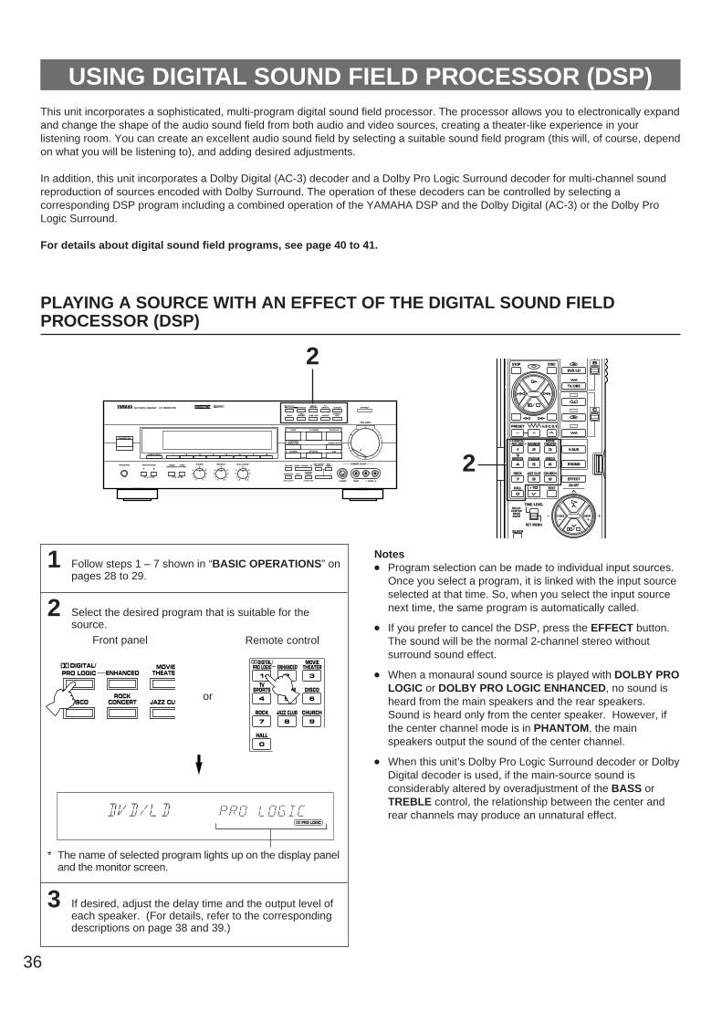
36
USING DIGITAL SOUND FIELD PROCESSOR (DSP)This unit incorporates a sophisticated, multi-program digital sound field processor. The processor allows you to electronically expandand change the shape of the audio sound field from both audio and video sources, creating a theater-like experience in yourlistening room. You can create an excellent audio sound field by selecting a suitable sound field program (this will, of course, dependon what you will be listening to), and adding desired adjustments.
In addition, this unit incorporates a Dolby Digital (AC-3) decoder and a Dolby Pro Logic Surround decoder for multi-channel soundreproduction of sources encoded with Dolby Surround. The operation of these decoders can be controlled by selecting acorresponding DSP program including a combined operation of the YAMAHA DSP and the Dolby Digital (AC-3) or the Dolby ProLogic Surround.
For details about digital sound field programs, see page 40 to 41.
PLAYING A SOURCE WITH AN EFFECT OF THE DIGITAL SOUND FIELDPROCESSOR (DSP)
1 Follow steps 1 – 7 shown in “BASIC OPERATIONS” onpages 28 to 29.
2 Select the desired program that is suitable for thesource.
* The name of selected program lights up on the display paneland the monitor screen.
3 If desired, adjust the delay time and the output level ofeach speaker. (For details, refer to the correspondingdescriptions on page 38 and 39.)
Notes Program selection can be made to individual input sources.
Once you select a program, it is linked with the input sourceselected at that time. So, when you select the input sourcenext time, the same program is automatically called.
If you prefer to cancel the DSP, press the EFFECT button.The sound will be the normal 2-channel stereo withoutsurround sound effect.
When a monaural sound source is played with DOLBY PROLOGIC or DOLBY PRO LOGIC ENHANCED, no sound isheard from the main speakers and the rear speakers.Sound is heard only from the center speaker. However, ifthe center channel mode is in PHANTOM, the mainspeakers output the sound of the center channel.
When this unit’s Dolby Pro Logic Surround decoder or DolbyDigital decoder is used, if the main-source sound isconsiderably altered by overadjustment of the BASS orTREBLE control, the relationship between the center andrear channels may produce an unnatural effect.
DIGITAL/PRO LOGIC ENHANCED
MOVIETHEATER
TVSPORTS STADIUM
STANDBY/ON
NATURAL SOUND AV RECEIVER
SPEAKERSPHONES
A
ON OFF ON OFF
B
BASS TREBLE BALANCE VIDEO AUX
S VIDEO VIDEO L AUDIO R
VOLUME
5 54
3
2l 0 l
2
3
45 5
4
3
2l 0 l
2
3
4L R
l620
28
40
60
l2
8
4
2
0–dB
BASSEXTENSION
TONEBYPASS
CINEMA DSP
5 54
3
2l 0 l
2
3
4
DELAY/CENTER/REAR/SWFRFM/AM
MAN’L/AUTO FM
TUNINGMODE
AUTO/MAN’L MONO
SETMENU
DISCOCONCERT
HALLROCK
CONCERT
EFFECT
CHURCHJAZZ CLUB
DOWN TUNING UP
MEMORY EDIT
VCR DVD/LDTV/DBS
TAPE/MDMONITOR VIDEO AUX
TUNER CDPHONO
A/B/C/D/E 1 2 3 4 5 6 7 8
2 BDVD/LD
V-AUX
PHONO
EFFECT
ON/OFF
TV/DBS
C
DISCSTOP
PRESET A/B/C/D/E
DIGITAL/PRO LOGIC ENHANCED
MOVIETHEATER
1 2 3
SPORTS STADIUM DISCOTV
4 5 6
ROCK JAZZ CLUB CHURCH
7 8 9
HALL
TIME/LEVEL
SET MENU
DELAYCENTERREARSWFR
TEST
SLEEP
0
+10
2
ROOM 2 CONTROL
NORMAL WIDE PHANTOMAUTO SPEAKERS
PRO LOGIC
A SPEAKERS B
Front panel Remote control
DIGITAL/PRO LOGIC ENHANCED
MOVIETHEATE
DISCOROCK
CONCERT JAZZ CLU
1 2 3
SPORTS STADIUM DISCOTV
4 5 6
ROCK JAZZ CLUB CHURCH
7 8 9
HALL
0
DIGITAL/PRO LOGIC ENHANCED
MOVIETHEATER
or
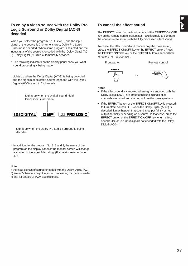
To enjoy a video source with the Dolby ProLogic Surround or Dolby Digital (AC-3)decoded
When you select the program No. 1, 2 or 3, and the inputsignal of the source is 2-channel stereo, Dolby Pro LogicSurround is decoded. When some program is selected and theinput signal of the source is encoded with the Dolby Digital (AC-3), Dolby Digital (AC-3) is automatically decoded.
* The following indicators on the display panel show you whatsound processing is being made.
* In addition, for the program No. 1, 2 and 3, the name of theprogram on the display panel or the monitor screen will changeaccording to the type of decoding. (For details, refer to page40.)
NoteIf the input signals of source encoded with the Dolby Digital (AC-3) are in 2-channels only, the sound processing for them is similarto that for analog or PCM audio signals.
To cancel the effect sound
The EFFECT button on the front panel and the EFFECT ON/OFFkey on the remote control transmitter make it simple to comparethe normal stereo sound with the fully processed effect sound.
To cancel the effect sound and monitor only the main sound,press the EFFECT ON/OFF key or the EFFECT button. Pressthe EFFECT ON/OFF key or the EFFECT button a second timeto restore normal operation.
Notes If the effect sound is canceled when signals encoded with the
Dolby Digital (AC-3) are input to this unit, signals of allchannels are mixed and are output from the main speakers.
If the EFFECT button or the EFFECT ON/OFF key is pressedto turn effect sounds OFF when the Dolby Digital (AC-3) isdecoded, it may happen that sound is output faintly or notoutput normally depending on a source. In that case, press theEFFECT button or the EFFECT ON/OFF key to turn effectsounds ON, or use input signals not encoded with the DolbyDigital (AC-3).
37
En
glish
Lights up when the Dolby Digital (AC-3) is being decodedand the signals of selected source encoded with the DolbyDigital (AC-3) is not in 2-channels.
Lights up when the Digital Sound FieldProcessor is turned on.
Lights up when the Dolby Pro Logic Surround is beingdecoded
3 DIGITAL DSP PRO LOGIC
Front panel
or
Remote control
EFFECTEFFECT
ON/OFF

38
ADJUSTING DELAY TIME AND EACH SPEAKER OUTPUT LEVEL
In using the digital sound field processor including the Dolby ProLogic Decoder or the Dolby Digital (AC-3) Decoder, you canadjust delay time between the main sound and effect sound, andeach speaker output level as you prefer.
Note: These adjustments can be made only when the effectsound is on. If none of the indicators , and
are not illuminated on the display panel, pressthe EFFECT switch on the front panel or the EFFECT ON/OFFkey on the remote control transmitter so that at least one ofthose indicators lights up on the display panel.
PRO LOGICDIGITALDSP
If you will use the remote control transmitter, set theTIME/LEVEL·SET MENU switch to the TIME/LEVELposition on the remote control transmitter.Note: Be sure to use the remote control transmitter with thelid open.
1 Press once or more until the name of item on which youwill make an adjustment appears on the display panel.
Whenever pressed, the selection changes as the above chartshows.
* Pressing the key on the remote control transmitterchanges the selection in the reverse order.
* Depending on a mode of this unit, you cannot select allitems.
2 Adjust the level on the selected item.
3 Repeat step 1 and 2 to make adjustments on other items.Front panel
or
Remote control
DELAY/CENTER/REAR/SWFR
SETMENU
D E L A Y
C E N T E R
R S U R .
L S U R .
S W F R
(Delay time)
(Center speaker output level)
(Right rear speaker output level)
(Left rear speaker output level)
(Subwoofer output level)
or
Front panel Remote control
DELAY/CENTER/REAR/SWFR
SETMENU
Method of adjustment
TIME/LEVEL
SET MENU

39
En
glish
NoteThe values of the delay time, center level, rear level andsubwoofer output level you set the last time will remainmemorized even when this unit is in the standby mode.However, if the power cord is kept disconnected for more thanone week, these values will be automatically changed back tothe original factory settings.
Adjusting delay time
You can adjust the time difference between the beginning ofthe sound from the main speakers and the beginning of theeffect sound from the rear or front effect speakers.The larger the value, the later the effect sound is generated. This adjustment can be made to all programs individually.
Notes Adding too much delay will cause an unnatural effect with
some sources.
When the –/+ button is pressed, sound is momentarilyinterrupted.
Program
1. DOLBY PRO LOGICDOLBY DIGITAL
2. PRO LOGIC ENHANCEDDOLBY DIGITAL ENHANCED
3. 70 mm MOVIE THEATERDIGITAL MOVIE THEATER
4. TV SPORTS5. STADIUM6. DISCO7. ROCK CONCERT8. JAZZ CLUB9. CHURCH10. CONCERT HALL
Control range (ms)
15 to 300 to 1515 to 300 to 1515 to 301 to 501 to 501 to 501 to 501 to 501 to 501 to 501 to 50
Speakers
CENTERRIGHT SURROUNDLEFT SURROUNDSUBWOOFER
Preset value
0000
Control range (dB)
MIN, –20 to +10MIN, –20 to +10MIN, –20 to +10MIN, –20 to 0
If desired, you can adjust the sound output level of the eachspeaker even if the output level is already set in “SPEAKERBALANCE ADJUSTMENT” on pages 24 to 25.
Notes Output level of the center speaker cannot be adjusted when
the program STADIUM, DISCO, ROCK CONCERT, JAZZCLUB, CHURCH or CONCERT HALL is selected, and theinput signal is analog, PCM audio or encoded with theDolby Digital (AC-3) in 2-channels.
If the function “4. CENTER SPEAKER” in the SET MENUmode is set in the “PHNTM (phantom)” position, the soundoutput level of the center speaker cannot be adjusted. Thisis because in this mode, the center sound is automaticallyoutput from the left and right main speakers.
Once the output level is adjusted, the level value will be thesame in all the digital sound field programs.
Adjusting output level of the center, right rear and left rear speakers, and subwoofer
Preset value
20152015172220451422264030

40
The following list gives you a brief description of the sound fields produced by each of the DSP programs. Keep in mind that most ofthese are precise digital recreations of actual acoustic environments. The data for these sound fields was recorded at actuallocations using sophisticated sound field measurement equipment.NoteThe channel level balance between the left and right rear effect speakers may vary depending on the sound field you arelistening to. This is due to the fact that most of these sound field recreations are actual acoustic environments.
FEATURE
Reproduces video discs, video tapes and similar sources which are DolbySurround encoded and bear the “DOLBY SURROUND” logo.
The built-in Dolby Pro Logic Surround decoder or Dolby Digital (AC-3)decoder precisely reproduces sounds and sound effects of a sourceencoded with Dolby Surround. The realization of a highly efficient decodingprocess improves crosstalk and channel separation and makes soundpositioning smoother and more precise.
Reproduces video discs, video tapes and similar sources which are DolbySurround encoded and bear the “DOLBY SURROUND” logo.
This program ideally simulates the multi-surround speaker systems of the 35mm film theater. The Dolby Surround decoding and the digital sound fieldprocessing is precisely performed without altering the originally designedsound orientation. The surround effects produced by this sound field foldsthe viewer naturally from the rear to the left and right and toward the screen.
Note: If the main channel sound is considerably altered by overadjustmentof the BASS or TREBLE controls, the relationship with the rear channelsmay produce an unnatural effect.
Ideal for reproducing video discs, video tapes and similar sources which areDolby Surround encoded and bear the “DOLBY SURROUND” logo.
This program is ideal for precisely reproducing the sound design of thenewest 70 mm/Dolby Digital multi-track films. The sound field is made to besimilar to that of the newest movie theaters, so the reverberations of thesound field itself are restrained as much as possible. The three dimensionalfeeling of the sound field is emphasized, and dialog is precisely oriented onthe screen. You can enjoy watching Sci-Fi, adventure movies, etc. withmuch presence.
No. PROGRAM
1 DOLBY PRO LOGIC ( )Functions when the input signal is analog orPCM audio.Speaker output: main, center, rear
DOLBY DIGITAL ( )Functions when the input signal is DolbyDigital.Speaker output: main, center, rear
2 DOLBY PRO LOGIC ENHANCED( )
Functions when the input signal is analog orPCM audio.Speaker output: main, center, rear
DOLBY DIGITAL ENHANCED( )
Functions when the input signal is DolbyDigital.Speaker output: main, center, rear
3 70 mm MOVIE THEATER( )Functions when the input signal is analog orPCM audio.Speaker output: main, center, rear
DIGITAL MOVIE THEATER( )
Functions when the input signal is DolbyDigital.Speaker output: main, center, rear
DIGITAL DSP
DSP PRO LOGIC
DIGITAL DSP
DSP PRO LOGIC
DIGITAL
PRO LOGIC
BRIEF OVERVIEW OF DIGITAL SOUND FIELD PROGRAMS
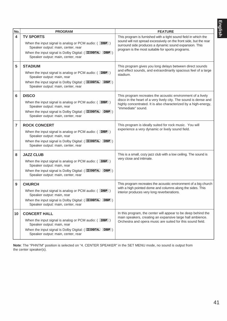
41
En
glishFEATURE
This program is furnished with a tight sound field in which thesound will not spread excessively on the front side, but the rearsurround side produces a dynamic sound expansion. Thisprogram is the most suitable for sports programs.
This program gives you long delays between direct soundsand effect sounds, and extraordinarily spacious feel of a largestadium.
This program recreates the acoustic environment of a livelydisco in the heart of a very lively city. The sound is dense andhighly concentrated. It is also characterized by a high-energy,“immediate” sound.
This program is ideally suited for rock music. You willexperience a very dynamic or lively sound field.
This is a small, cozy jazz club with a low ceiling. The sound isvery close and intimate.
This program recreates the acoustic environment of a big churchwith a high pointed dome and columns along the sides. Thisinterior produces very long reverberations.
In this program, the center will appear to be deep behind themain speakers, creating an expansive large hall ambience.Orchestra and opera music are suited for this sound field.
No. PROGRAM
4 TV SPORTS
When the input signal is analog or PCM audio: ( )Speaker output: main, center, rear
When the input signal is Dolby Digital: ( )Speaker output: main, center, rear
5 STADIUM
When the input signal is analog or PCM audio: ( )Speaker output: main, rear
When the input signal is Dolby Digital: ( )Speaker output: main, center, rear
6 DISCO
When the input signal is analog or PCM audio: ( )Speaker output: main, rear
When the input signal is Dolby Digital: ( )Speaker output: main, center, rear
7 ROCK CONCERT
When the input signal is analog or PCM audio: ( )Speaker output: main, rear
When the input signal is Dolby Digital: ( )Speaker output: main, center, rear
8 JAZZ CLUB
When the input signal is analog or PCM audio: ( )Speaker output: main, rear
When the input signal is Dolby Digital: ( )Speaker output: main, center, rear
9 CHURCH
When the input signal is analog or PCM audio: ( )Speaker output: main, rear
When the input signal is Dolby Digital: ( )Speaker output: main, center, rear
10 CONCERT HALL
When the input signal is analog or PCM audio: ( )Speaker output: main, rear
When the input signal is Dolby Digital: ( )Speaker output: main, center, rear
DIGITAL DSP
DSP
DIGITAL DSP
DSP
DIGITAL DSP
DSP
DIGITAL DSP
DSP
DIGITAL DSP
DSP
DIGITAL DSP
DSP
DIGITAL DSP
DSP
Note: The “PHNTM” position is selected on “4. CENTER SPEAKER” in the SET MENU mode, no sound is output fromthe center speaker(s).

42
1
Whenever the SLEEP key is pressed, the SLEEP time willchange as follows.
After a while, the display returns to the indication beforethe SLEEP timer is set.
2 The unit will be turned into the standby modeautomatically at the selected SLEEP time.
To cancel the selected SLEEP time
Press once or more so that “SLEEP OFF” appears on thedisplay. (It will soon disappear and the “SLEEP” indicator willgo off from the display.)
NoteThe SLEEP timer setting can also be canceled by turning thisunit into the standby mode with the STANDBY/ON switch onthe front panel (or the STANDBY key on the remote controltransmitter) or disconnecting the power plug of this unit fromthe AC outlet.
SETTING THE SLEEP TIMER
A
B
C
REMOTE CONTROLTRANSMITTER
SLEEP
A
B
C
REMOTE CONTROLTRANSMITTER
SLEEP
If you use the SLEEP timer of this unit, you can make this unit turn into the standby mode. When you are going to sleep whileenjoying a broadcast or other desired input source, this timer function is helpful.
Notes The SLEEP timer can be controlled only with the remote control transmitter. The components on which the SLEEP timer is effective are the sources connected to the SWITCHED AC OUTLET(S) on the rear
panel of this unit.
To set the SLEEP time
Press once or more to select the desiredSLEEP time.
120 90 60 30
The SLEEP timer is off (OFF).(The state before the SLEEP keyis pressed.)
(Minutes)
Indicates the SLEEP time.
Flashes.
SLEEP

43
En
glishBASIC OPERATIONS (When the lid is open)
The remote control transmitter provided with this unit is designed to control all the most commonly used functions of this unit. If theCD player, tape deck, LD player, DVD player, etc. connected to this unit are YAMAHA components designed for remote controlcompatibility, then this remote control transmitter will also control various functions of each component.* For basic operations, use the remote control transmitter with the lid open.
NAMES OF KEYS AND THEIR FUNCTIONS
MA
CR
OQ
UIC
KO
FFSLO
W
TAPE
A/BREC/PAUSE
BA
ACD
TUNER
VCR
BDVD/LD
V-AUX
PHONO
EFFECT
ON/OFF
TV/DBS
C
DIR
DISCSTOP
TRANSMIT/LEARN
LEARNCLEAR MACRO
PRESET A/B/C/D/E
DIGITAL/PRO LOGIC ENHANCED
MOVIETHEATER
1 2 3
SPORTS STADIUM DISCOTV
4 5 6
ROCK JAZZ CLUB CHURCH
7 8 9
HALL
TIME/LEVEL
SET MENU
DELAYCENTERREARSWFR
TEST
SLEEP
MASTER VOLUME
TV
VCRSTANDBY
SYSTEMPOWER ON
0
+10
MUTE
REMOTE CONTROLTRANSMITTER
1
3
2
4
7
9
B
F
D
D
E
C
A
0
8
5
G
6
Lid is opened. Side panel
REMOTE CONTROL TRANSMITTER

44
1 Tape deck keysControls tape deck.(The A/B/C switch (F) should be set to the “A” position.)* DIR A, B and A/B are applicable only to double
cassette tape deck.* For a single cassette deck with automatic reverse
function, pressing DIR A will reverse the direction of tape running.
2 CD/LD/DVD player keysControls compact disc player, LD player or DVD player.(To control compact disc player, set the A/B/C switch (F) tothe “A” position. To control LD player or DVD player, set theA/B/C switch (F) to the “C” position.)* DISC is applicable only to compact disc changer.* STOP is applicable only to LD player or DVD player.
3 Tuner keysControls tuner.(The A/B/C switch (F) should be set to the “A” position.)+: Selects higher preset station number.–: Selects lower preset station number.A/B/C/D/E: Selects the group (A – E) of preset station
numbers.
4 DSP program selector keysSelects a DSP program when the built-in digital sound fieldprocessor (including the Dolby Pro Logic Surround decoderand the Dolby Digital (AC-3) decoder) is on.
5 TEST keyUsed for speaker balance adjustment. (For details, refer topage 24–25.)
6 TIME/LEVEL·SET MENU switchSet to the TIME/LEVEL position when you will make anadjustment on delay time, center speaker output level, rearspeaker output level or subwoofer level. Set to the SET MENUposition when you will make an adjustment or setting changeon a function in the SET MENU mode.
7 SLEEP timer keyThis key is used to turn the built-in SLEEP timer on and off,and to set the SLEEP time. (For details, refer to page 42.)
8 SYSTEM POWER ON and STANDBY keysPressing the SYSTEM POWER ON key turns the power to thisunit on and pressing the STANDBY key turns this unit into thestandby mode.
9 RESET buttonThis button is inside the battery compartment.Press this button to “reset” the internal microcomputer whichcontrols remote control operations. Microcomputer “reset” isnecessary when the remote control freezes.* Pressing the RESET button will not erase learned
functions.
0 MASTER VOLUME (up) and (down) keysTurns the volume level up and down.
A MUTE keyWhen pressed, this key mutes the volume level. To resume theoriginal volume level, press this key again.While muting, the indicator on the VOLUME control flashescontinuously.
B / and –/+ keys(up) and (down) keys change items (or functions) in the
mode selected by the TIME/LEVEL·SET MENU switch. – and+ keys make an adjustment or setting change on the item (orfunction) selected by the or key.
C EFFECT ON/OFF keySwitches on/off the digital sound field processor (including theDolby Pro Logic Surround decoder and the Dolby Digital (AC-3) decoder).
D Input selector keysSelects input source.
E A/B/C indicatorsThe position (A, B or C) selected by the A/B/C switch is shownin red.
F A/B/C switchThis switch must be used only when the lid of the remotecontrol transmitter is open. (This switch will not function whenthe lid is closed.) Normally, set this switch to the “A” position. When controlling aYamaha LD player or DVD player by using the CD/LD/DVDplayer keys (2), set this switch to the “C” position.
G TRANSMIT/LEARN indicatorLights up when the remote control transmitter is transmittinginfrared signals (when a command key is pressed).
NoteWhen using the keys to control Yamaha components,identify them with your component’s keys. If these keysare identical, their functions will be the same. For each keyfunction, refer to the corresponding instruction in yourcomponent’s manual.
RESET button

45
En
glishLEARNING NEW CONTROL FUNCTIONS (When the lid is open)
This is a learning remote control transmitter. The shaded keys in the illustration shown below can be programmed to “learn”control functions from other remote control transmitters. By learning key-functions from other remote control transmitter, this unit canthen be used in place of one or more other remote control transmitters, thus making operation of your various audio and videocomponents more convenient. Some of the “learning-capable” keys are originally empty and others have already been preset with functions to control this unit andother Yamaha components. You can store new functions to them (in place of preset functions) as desired.* See page 50 for the learning method.* See page 52 for clearing a learned function (or all learned functions).NoteIf the memory capacity of the remote control transmitter becomes full, no further learning is possible even if some learning-capablekeys are not occupied with new functions. If, for example, you store Yamaha codes only into this remote control transmitter, up toabout 20 functions can be stored. Store new functions to the learnable-capable keys which are useful for you.
Keys which can have three functions (1, 2, 3, 4)
In the “Learning-capable” keys, the keys numbered 1–4 in theillustration at left can have three functions. This is because theyhave three memory areas (A, B and C). (One function per area.)You can store new functions into the area B and C, and use threefunctions on a key by switching the memory areas with the A/B/Cswitch. (Area A cannot learn a new function.)
To use these keys:1. Before using a key, select the area A, B or C of the key on which
the function you want to use is stored by using the A/B/C switch.2. Press the key.
The original factory settings of these keys are as follows.
APreset withfunctions forcontrolling aYamaha tape deck.Preset withfunctions forcontrolling aYamaha CD player. (STOP is empty.)Preset withfunctions forcontrolling the built-in tuner.Preset as the DSPprogram selectorkeys (1–9, 0) andthe TEST key.(+10 is empty.)
BEmpty
Empty
Empty
Preset as the DSPprogram selectorkeys (1–9, 0) andthe TEST key.(+10 is empty.)
CEmpty
Preset with functionsfor controlling aYamaha LD playerand DVD player. (DISC is empty.)Empty
Preset as the DSPprogram selectorkeys (1–9, 0) andthe TEST key.(+10 is empty.)
1
2
3
4
The position of A/B/C switch
NoteThe area A of all keys cannot learn new functions. To store newfunctions to these keys, store them onto the area B or C.
Empty keys (1, 2)
These are empty keys. Each key can learn a function from anotherremote control transmitter. For example, the TV key is useful for storing the function of yourTV’s power switch, and the VCR key can be used for your VCR’spower switch.
TAPE
ACD
TUNER
VCR
BDVD/LD
V-AUX
PHONO
EFFECT
ON/OFF
TV/DBS
C
TRANSMIT/LEARN
LEARNCLEAR MACRO
TIME/LEVEL
SET MENU
DELAYCENTERREARSWFR
SLEEP
MASTER VOLUME
TV
VCRSTANDBY
SYSTEMPOWER ON
MUTE
REMOTE CONTROLTRANSMITTER
A/BREC/PAUSE
BA DIR
DISCSTOP
PRESET A/B/C/D/E
DIGITAL/PRO LOGIC ENHANCED
MOVIETHEATER
1 2 3
SPORTS STADIUM DISCOTV
4 5 6
ROCK JAZZ CLUB CHURCH
7 8 9
HALL TEST
0
+10
1
1
2
3
4
2
A/B
/C s
wit
ch
Lid is open.
*1: These buttons are used for learning a new function
or clearing a learned function (or all learnedfunctions). For details, refer to page 50 to 52 .
*1
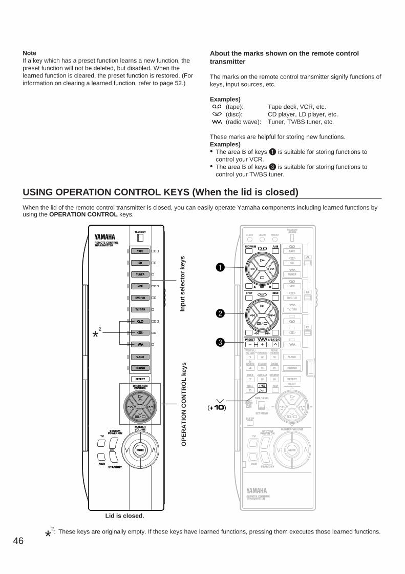
46
NoteIf a key which has a preset function learns a new function, thepreset function will not be deleted, but disabled. When thelearned function is cleared, the preset function is restored. (Forinformation on clearing a learned function, refer to page 52.)
About the marks shown on the remote controltransmitter
The marks on the remote control transmitter signify functions ofkeys, input sources, etc.
Examples)(tape): Tape deck, VCR, etc.(disc): CD player, LD player, etc.(radio wave): Tuner, TV/BS tuner, etc.
These marks are helpful for storing new functions. Examples)• The area B of keys 1 is suitable for storing functions to
control your VCR.• The area B of keys 3 is suitable for storing functions to
control your TV/BS tuner.
USING OPERATION CONTROL KEYS (When the lid is closed)
When the lid of the remote control transmitter is closed, you can easily operate Yamaha components including learned functions byusing the OPERATION CONTROL keys.
TAPE
ACD
TUNER
VCR
BDVD/LD
V-AUX
PHONO
EFFECT
ON/OFF
TV/DBS
C
DIR
TRANSMIT/LEARN
LEARNCLEAR MACRO
PRESET A/B/C/D/E
SLEEP
MASTER VOLUME
TV
VCRSTANDBY
SYSTEMPOWER ON
MUTE
REMOTE CONTROLTRANSMITTER
REMOTE CONTROLTRANSMITTER
TAPE
CD
TUNER
VCR
DVD/LD
V-AUX
PHONO
TV/DBS
TV
VCR
MUTE
MASTERVOLUME
OPERATIONCONTROL
EFFECT
TRANSMIT
DISCSTOP
A/BREC/PAUSE
BA
DIGITAL/PRO LOGIC ENHANCED
MOVIETHEATER
1 2 3
SPORTS STADIUM DISCOTV
4 5 6
ROCK JAZZ CLUB CHURCH
7 8 9
HALL
TIME/LEVEL
SET MENU
DELAYCENTERREARSWFR
TEST
0
+10
STANDBY
SYSTEMPOWER ON
1
2
3
(+10)
Inp
ut
sele
cto
r ke
ysO
PE
RA
TIO
N C
ON
TR
OL
key
s
Lid is closed.
*2: These keys are originally empty. If these keys have learned functions, pressing them executes those learned functions.
*2
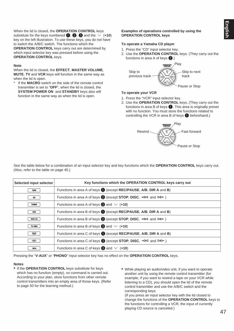
47
En
glishWhen the lid is closed, the OPERATION CONTROL keys
substitute for the keys numbered 1, 2, 3 and the (+10)key on the left illustration. To use these keys, you do not haveto switch the A/B/C switch. The functions which theOPERATION CONTROL keys carry out are determined bywhich input selector key was pressed before using theOPERATION CONTROL keys.
NoteWhen the lid is closed, the EFFECT, MASTER VOLUME,MUTE, TV and VCR keys will function in the same way aswhen the lid is open.* If the MACRO switch on the side of the remote control
transmitter is set to “OFF”, when the lid is closed, theSYSTEM POWER ON and STANDBY keys also willfunction in the same way as when the lid is open.
Examples of operations controlled by using theOPERATION CONTROL keys
To operate a Yamaha CD player
1. Press the “CD” input selector key.2. Use the OPERATION CONTROL keys. (They carry out the
functions in area A of keys 2.)
To operate your VCR
1. Press the “VCR” input selector key.2. Use the OPERATION CONTROL keys. (They carry out the
functions in area B of keys 1. This area is originally presetwith no function. You must store the functions related tocontrolling the VCR in area B of keys 1 beforehand.)
Selected input selector Key functions which the OPERATION CONTROL keys carry out
Functions in area A of keys 1 (except REC/PAUSE, A/B, DIR A and B)
Functions in area A of keys 2 (except STOP, DISC, and )
Functions in area A of keys 3 and (+10)
Functions in area B of keys 1 (except REC/PAUSE, A/B, DIR A and B)
Functions in area B of keys 2 (except STOP, DISC, and )
Functions in area B of keys 3 and (+10)
Functions in area C of keys 1 (except REC/PAUSE, A/B, DIR A and B)
Functions in area C of keys 2 (except STOP, DISC, and )
Functions in area C of keys 3 and (+10)
Notes• If the OPERATION CONTROL keys substitute for keys
which has no function (empty), no command is carried out.According to your plan, store functions from other remotecontrol transmitters into an empty area of those keys. (Referto page 50 for the learning method.)
• While playing an audio/video unit, if you want to operateanother unit by using the remote control transmitter (forexample, if you want to rewind a tape on your VCR whilelistening to a CD), you should open the lid of the remotecontrol transmitter and use the A/B/C switch and thecorresponding keys. (If you press an input selector key with the lid closed tochange the functions of the OPERATION CONTROL keys tothe functions for controlling a VCR, the input of currentlyplaying CD source is canceled.)
See the table below for a combination of an input selector key and key functions which the OPERATION CONTROL keys carry out.(Also, refer to the table on page 45.)
Pressing the “V-AUX” or “PHONO” input selector key has no effect on the OPERATION CONTROL keys.
TAPE
CD
TUNER
VCR
DVD/LD
TV/DBS
OPERATIONCONTROL
Play
Skip toprevious track
Skip to nexttrack
Pause or Stop
OPERATIONCONTROL
Play
Rewind Fast forward
Pause or Stop
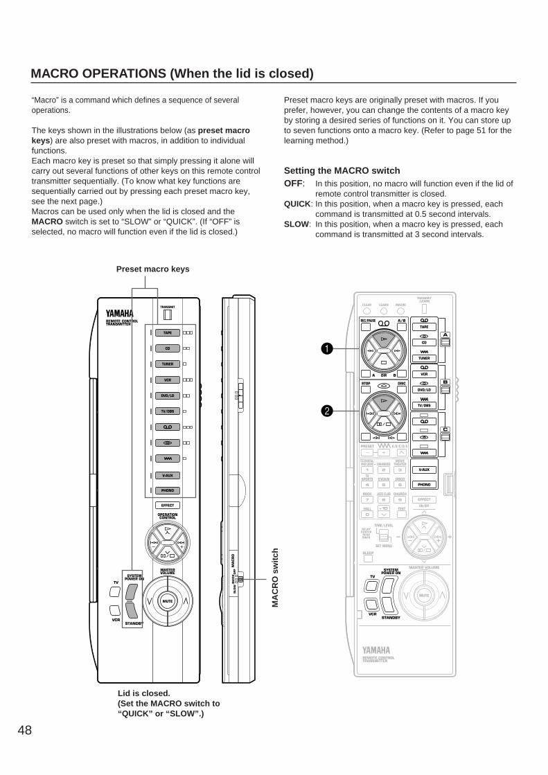
48
MACRO OPERATIONS (When the lid is closed)
“Macro” is a command which defines a sequence of severaloperations.
The keys shown in the illustrations below (as preset macrokeys) are also preset with macros, in addition to individualfunctions. Each macro key is preset so that simply pressing it alone willcarry out several functions of other keys on this remote controltransmitter sequentially. (To know what key functions aresequentially carried out by pressing each preset macro key,see the next page.)Macros can be used only when the lid is closed and theMACRO switch is set to “SLOW” or “QUICK”. (If “OFF” isselected, no macro will function even if the lid is closed.)
Preset macro keys are originally preset with macros. If youprefer, however, you can change the contents of a macro keyby storing a desired series of functions on it. You can store upto seven functions onto a macro key. (Refer to page 51 for thelearning method.)
Setting the MACRO switchOFF: In this position, no macro will function even if the lid of
remote control transmitter is closed.QUICK: In this position, when a macro key is pressed, each
command is transmitted at 0.5 second intervals.SLOW: In this position, when a macro key is pressed, each
command is transmitted at 3 second intervals.
REMOTE CONTROLTRANSMITTER
TAPE
CD
TUNER
VCR
DVD/LD
V-AUX
PHONO
TV/DBS
TV
VCRSTANDBY
SYSTEMPOWER ON
MUTE
MASTERVOLUME
OPERATIONCONTROL
EFFECT
TRANSMIT
MA
CR
OQ
UIC
KO
FFSLO
W
TAPE
ACD
TUNER
VCR
BDVD/LD
V-AUX
PHONO
EFFECT
ON/OFF
TV/DBS
C
DIR
TRANSMIT/LEARN
LEARNCLEAR MACRO
PRESET A/B/C/D/E
HALL TEST
MASTER VOLUME
TV
VCRSTANDBY
SYSTEMPOWER ON
0
+10
MUTE
REMOTE CONTROLTRANSMITTER
DISCSTOP
A/BREC/PAUSE
BA
1
2
SLEEP
DIGITAL/PRO LOGIC ENHANCED
MOVIETHEATER
1 2 3
SPORTS STADIUM DISCOTV
4 5 6
ROCK JAZZ CLUB CHURCH
7 8 9
TIME/LEVEL
SET MENU
DELAYCENTERREARSWFR
Lid is closed.(Set the MACRO switch to“QUICK” or “SLOW”.)
Preset macro keysM
AC
RO
sw
itch
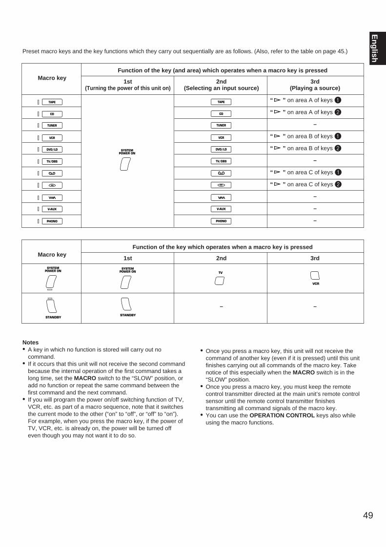
49
En
glish
Macro key1st
(Turning the power of this unit on)2nd
(Selecting an input source)3rd
(Playing a source)
“ ” on area A of keys 1
“ ” on area A of keys 2
–
“ ” on area B of keys 1
“ ” on area B of keys 2
–
“ ” on area C of keys 1
“ ” on area C of keys 2
–
–
–
Function of the key (and area) which operates when a macro key is pressed
Macro key1st 2nd
–
3rd
–
Function of the key which operates when a macro key is pressed
Preset macro keys and the key functions which they carry out sequentially are as follows. (Also, refer to the table on page 45.)
Notes• A key in which no function is stored will carry out no
command. • If it occurs that this unit will not receive the second command
because the internal operation of the first command takes along time, set the MACRO switch to the “SLOW” position, oradd no function or repeat the same command between thefirst command and the next command.
• If you will program the power on/off switching function of TV,VCR, etc. as part of a macro sequence, note that it switchesthe current mode to the other (“on” to “off”, or “off” to “on”).For example, when you press the macro key, if the power ofTV, VCR, etc. is already on, the power will be turned offeven though you may not want it to do so.
• Once you press a macro key, this unit will not receive thecommand of another key (even if it is pressed) until this unitfinishes carrying out all commands of the macro key. Takenotice of this especially when the MACRO switch is in the“SLOW” position.
• Once you press a macro key, you must keep the remotecontrol transmitter directed at the main unit’s remote controlsensor until the remote control transmitter finishestransmitting all command signals of the macro key.
• You can use the OPERATION CONTROL keys also whileusing the macro functions.
TAPE
CD
TUNER
VCR
DVD/LD
V-AUX
PHONO
TV/DBS
TAPE
CD
TUNER
VCR
DVD/LD
V-AUX
PHONO
TV/DBS
SYSTEMPOWER ON
SYSTEMPOWER ON
STANDBY
SYSTEMPOWER ON
STANDBY
TV
VCR
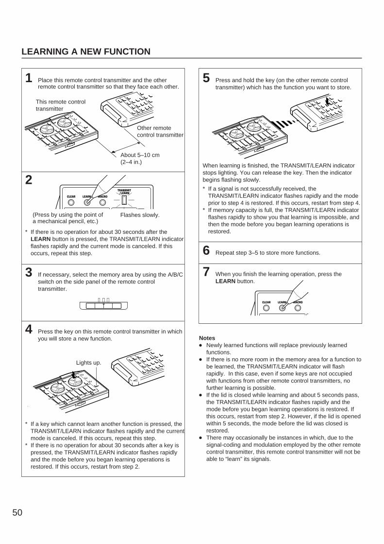
50
LEARNING A NEW FUNCTION
1 Place this remote control transmitter and the otherremote control transmitter so that they face each other.
2
* If there is no operation for about 30 seconds after theLEARN button is pressed, the TRANSMIT/LEARN indicatorflashes rapidly and the current mode is canceled. If thisoccurs, repeat this step.
3 If necessary, select the memory area by using the A/B/Cswitch on the side panel of the remote controltransmitter.
4 Press the key on this remote control transmitter in whichyou will store a new function.
* If a key which cannot learn another function is pressed, theTRANSMIT/LEARN indicator flashes rapidly and the currentmode is canceled. If this occurs, repeat this step.
* If there is no operation for about 30 seconds after a key ispressed, the TRANSMIT/LEARN indicator flashes rapidlyand the mode before you began learning operations isrestored. If this occurs, restart from step 2.
5 Press and hold the key (on the other remote controltransmitter) which has the function you want to store.
When learning is finished, the TRANSMIT/LEARN indicatorstops lighting. You can release the key. Then the indicatorbegins flashing slowly.
* If a signal is not successfully received, theTRANSMIT/LEARN indicator flashes rapidly and the modeprior to step 4 is restored. If this occurs, restart from step 4.
* If memory capacity is full, the TRANSMIT/LEARN indicatorflashes rapidly to show you that learning is impossible, andthen the mode before you began learning operations isrestored.
6 Repeat step 3–5 to store more functions.
7 When you finish the learning operation, press theLEARN button.
Notes Newly learned functions will replace previously learned
functions. If there is no more room in the memory area for a function to
be learned, the TRANSMIT/LEARN indicator will flashrapidly. In this case, even if some keys are not occupiedwith functions from other remote control transmitters, nofurther learning is possible.
If the lid is closed while learning and about 5 seconds pass,the TRANSMIT/LEARN indicator flashes rapidly and themode before you began learning operations is restored. Ifthis occurs, restart from step 2. However, if the lid is openedwithin 5 seconds, the mode before the lid was closed isrestored.
There may occasionally be instances in which, due to thesignal-coding and modulation employed by the other remotecontrol transmitter, this remote control transmitter will not beable to “learn” its signals.
V-AUXPHONOEFFECTON/OFF
1
2
3
SPORTSSTADIUM
DISCO
TV4
5
6
ROCKJAZZ CLUB
CHURCH
7
8
9TEST
E
+10
Lights up.
V-AUXPHONOEFFECTON/OFF
1
2
3
ORTSSTADIUM
DISCO
TV
5
6
CLUBCHURCH9
EST
This remote controltransmitter
Other remotecontrol transmitter
About 5–10 cm (2–4 in.)
TRANSMIT/LEARN
LEARNCLEAR MACRO
Flashes slowly.(Press by using the point ofa mechanical pencil, etc.)
LEARNCLEAR MACRO
V-AUXPHONOEFFECTON/OFF
1
2
3
SPORTSSTADIUM
DISCO
TV4
5
6
OCKJAZZ CLUB
CHURCH
8
9TEST
10

51
En
glish
1
* If there is no operation for about 30 seconds after theMACRO button is pressed, the TRANSMIT/LEARNindicator flashes rapidly and the mode before you pressedthe MACRO button is restored. If this occurs, press theMACRO button again.
2 Press a preset macro key on which you want to make anew macro.
* If a key other than a preset macro key is pressed, theTRANSMIT/LEARN indicator flashes rapidly and the current mode is canceled. If this occurs, repeat this step.
3 Press and hold a key whose function you want to storeas the first function of the new macro.
When learning is finished, the TRANSMIT/LEARN indicatorlights up again. You can release the key.
* If a key whose function cannot be stored as a command ofmacro is pressed, the TRANSMIT/LEARN indicator flashesrapidly and the current mode is canceled. If this occurs,repeat this step.
* If about 30 seconds pass before a key is pressed, theTRANSMIT/LEARN indicator flashes rapidly and the modebefore you began learning operations is restored. If thisoccurs, restart from step 1.
4 Repeat step 3 to store the second, the third and morefunctions. You can store up to seven key functions inseries as a macro.
* If the seventh key function has been learned, theTRANSMIT/LEARN indicator flashes rapidly and the modebefore you began learning operations is restored. (Thisshows that the key has completed learning a series offunctions as a macro.) If this occurs, you do not have tofollow the next step.
5 When you finish learning, press the MACRO button.
MAKING A NEW MACRO
A new macro can be programmed onto any preset macro key in place of preset functions. (See page 48 to know what keys arepreset macro keys.) You can make as many as 13 new macro keys. A macro key can learn as many as seven functions of otherkeys.NoteIf you store a continuous command such as lowering of volume level, it will become a short command when it is carried out as a partof macro.
LEARNCLEAR MACRO
It is recommended to write down new key functions youstored on the provided user function stickers and pastethem on the reverse side of the remote control transmitteror the reverse side of the remote control transmitter’s lid.
Memory back-upAll of the learned functions will be retained while youreplace the batteries. However, if no batteries areinstalled for a few hours, the learned functions will beerased and will have to be learned again.
Goes off.
TRANSMIT/LEARN
LEARNCLEAR MACRO
Flashes slowly.
CD TRANSMIT/LEARN
Lights up.
SYSTEMPOWER ON TRANSMIT
/LEARN
A
B
C
REMOTE CONTROLTRANSMITTER
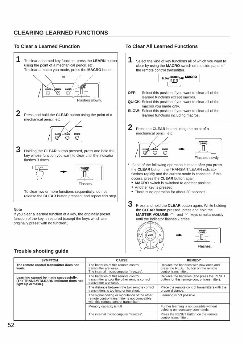
52
1 To clear a learned key function, press the LEARN buttonusing the point of a mechanical pencil, etc.To clear a macro you made, press the MACRO button.
2 Press and hold the CLEAR button using the point of amechanical pencil, etc.
3 Holding the CLEAR button pressed, press and hold thekey whose function you want to clear until the indicatorflashes 3 times.
To clear two or more functions sequentially, do notrelease the CLEAR button pressed, and repeat this step.
NoteIf you clear a learned function of a key, the originally presetfunction of the key is restored (except the keys which areoriginally preset with no function.)
To Clear a Learned Function To Clear All Learned Functions
1 Select the kind of key functions all of which you want toclear by using the MACRO switch on the side panel ofthe remote control transmitter.
OFF: Select this position if you want to clear all of thelearned functions except macros.
QUICK: Select this position if you want to clear all of themacros you made only.
SLOW: Select this position if you want to clear all of thelearned functions including macros.
2 Press the CLEAR button using the point of amechanical pencil, etc.
* If one of the following operation is made after you pressthe CLEAR button, the TRANSMIT/LEARN indicatorflashes rapidly and the current mode is canceled. If thisoccurs, press the CLEAR button again.• MACRO switch is switched to another position.• Another key is pressed.• There is no operation for about 30 seconds.
3 Press and hold the CLEAR button again. While holdingthe CLEAR button pressed, press and hold theMASTER VOLUME and keys simultaneouslyuntil the indicator flashes 7 times.
SYMPTOMThe remote control transmitter does notwork.
Learning cannot be made successfully.(The TRANSMIT/LEARN indicator does notlight up or flash.)
CAUSEThe batteries of this remote controltransmitter are weak.The internal microcomputer “freezes”.The batteries of this remote controltransmitter and/or the other remote controltransmitter are weak.The distance between the two remote controltransmitters is too long or too short.The signal coding or modulation of the otherremote control transmitter is not compatiblewith this remote control transmitter.Memory capacity is full.
The internal microcomputer “freezes”.
REMEDYReplace the batteries with new ones andpress the RESET button on the remotecontrol transmitter.Replace the batteries (and press the RESETbutton for this remote control transmitter).
Place the remote control transmitters with theproper distance.Learning is not possible.
Further learning is not possible withoutdeleting unnecessary commands.Press the RESET button on the remotecontrol transmitter.
Trouble shooting guide
MACROQUICKOFFSLOW
CLEARING LEARNED FUNCTIONS
TRANSMIT/LEARN
LEARNCLEAR MACRO
LEARNCLEAR MACRO
Flashes slowly.
or
CD TRANSMIT/LEARN
Flashes.
LEARNCLEAR MACRO
TRANSMIT/LEARN
Flashes slowly.
MUTE
TRANSMIT/LEARN
Flashes.

53
En
glish
Am
plif
ier
If the unit fails to operate normally, check the following points to determine whether the fault can be corrected by the simplemeasures suggested. If it cannot be corrected, or if the fault is not listed in the SYMPTOM column, disconnect the power cord andcontact your authorized YAMAHA dealer or service center for help.
SYMPTOM
The unit fails to turn on when theSTANDBY/ON switch is pressed, orturns into the standby mode suddenlysoon after the power is turned on.
It happens that this unit does not worknormally.
No sound or no picture.
No picture
The sound suddenly goes off.
Only one side speaker outputs thesound.
Sound “hums”.
The volume level is low while playing arecord.
The volume level cannot be increased,or sound is distorted.
No sound from the rear speakers.
No sound from the center speaker.
CAUSE
Power cord is not plugged in or is notcompletely inserted.
The IMPEDANCE SELECTOR switch on therear panel is not set to the upper or thelower end closely.
There is an influence of strong externalnoise (lightning, excessive static electricity,etc.) or a misoperation on this unit whileusing this unit.
Incorrect output cord connections.
Appropriate input source is not selected.
The SPEAKERS switches are not setproperly.
Speaker connections are not secure.
There is no S video terminal connectionbetween this unit and the TV, though Svideo signals are input to this unit.
The protection circuit has been activatedbecause of short circuit etc.
The SLEEP timer has functioned.
Incorrect setting of the BALANCE control.
Incorrect cord connections.
Incorrect cord connections.
No connection from the turntable to theGND terminal.
The record is being played on a turntablewith an MC cartridge.
The component connected to the REC OUTterminals of this unit is in the standby mode.
The sound output level to the rear speakersis set to minimum.
The monaural sound source is played inDOLBY PRO LOGIC or DOLBY PROLOGIC ENHANCED mode.
The sound output level to the centerspeaker is set to minimum.
The center channel mode is in PHANTOMmode.
Incorrect sound field program selection.
REMEDY
Firmly plug in the power cord.
Set the switch to the upper or the lower endclosely.
Turn this unit into the standby mode anddisconnect the AC power cord from the ACoutlet. After about 30 seconds have passed,connect the power and operate this unitagain.
Connect the cords properly. If the problempersists, the cords may be defective.
Select an appropriate input source with theinput selector buttons.
Set the SPEAKERS switch whichcorresponds to the speakers to be used tothe ON position.
Secure the connections.
Connect this unit’s S VIDEO MONITOR OUTterminal to the TV’s S video input terminal.
Turning the unit into the standby mode andthen on will reset the protection circuit.
Cancel the SLEEP timer function.
Adjust it to the appropriate position.
Connect the cords properly. If the problempersists, the cords may be defective.
Firmly connect the audio plugs. If theproblem persists, the cords may be defective.
Make the GND connection between theturntable and this unit.
The player should be connected to the unitthrough the MC head amplifier.
Turn the power to the component on.
Raise the sound output level to the rearspeakers.
Select another program suitable for themonaural sound source.
Raise the sound output level to the centerspeaker.
Select NORMAL or WIDE.
Select the appropriate program.
TROUBLESHOOTING

54
FM
AM
Oth
ers
Rem
ote
co
ntr
ol
tran
smit
ter
SYMPTOM
FM stereo reception is noisy.
There is distortion and clear receptioncannot be obtained even with a goodFM antenna.
A desired station cannot be tuned inwith the automatic tuning method.
Previously preset stations can nolonger be tuned in.
A desired station cannot be tuned inwith the automatic tuning method.
There are continuous crackling andhissing noises.
There are buzzing and whining noises(especially in the evening).
The remote control transmitter doesnot work.
The sound is degraded when listeningwith the headphones connected to thecompact disc player or cassette deckthat are connected with this unit.
CAUSE
Because of the characteristics of FM stereobroadcasts, this is limited to cases where thetransmitter is too far away or the antennainput is poor.
There is multipath interference.
The station is too weak.
This unit has been unplugged for a longperiod.
Weak signal or loose antenna connections.
Noises will result from ligtning, fluorescentlamps, motors, thermostats and otherelectrical equipment.
A television set is being used nearby.
Direct sunlight or lighting (of an inverter typeof fluorescent lamp etc.) is striking the remotecontrol sensor of the main unit.
The batteries of this remote controltransmitter are too weak.
This unit is in the standby mode.
REMEDY
Check the antenna connections.Try using a high quality directional FMantenna.Set the TUNING MODE button to the manualtuning mode.
Adjust antenna placement to eliminatemultipath interference.
Use the manual tuning method.Use a high quality directional FM antenna.
Repeat the presetting procedure.
Tighten the AM loop antenna connectionsand rotate it for best reception.
Use the manual tuning method.
Use an outdoor antenna and a ground wire.This will help somewhat but it is difficult toeliminate all noise.
Relocate this unit away from the TV.
Change the position of the main unit.
Replace the batteries with new ones.
Turn the power to this unit on.

55
En
glishAUDIO SECTION
Minimum RMS Output Power per ChannelMAIN L/R
8 ohms, 20 Hz to 20 kHz, 0.04% THD......................................................80W+80W
CENTER8 ohms, 20 Hz to 20 kHz, 0.07% THD................................................................80W
REAR L/R8 ohms, 20 Hz to 20 kHz, 0.07% THD......................................................80W+80W
Maximum Power [China and General modelsonly]
8 ohms, 1 kHz, 10% THDMAIN L/R................................125W+125W
Dynamic Power per Channel(by IHF Dynamic Headroom measuringmethod)
MAIN L/R8/6/4/2 ohms .................100/125/150/175W
Dynamic Headroom (8 ohms)[U.S.A. and Canada models only]...........................................................0.96 dB
IEC Power [Singapore model only]8 ohms, 1 kHz, 0.04% THD
MAIN L/R .............................................95W
Power Band Width MAIN L/R
8 ohms, 40W, 0.09% THD...........................................10 Hz to 50 kHz
Damping Factor (SPEAKERS A)MAIN L/R
8 ohms, 20 Hz to 20 kHz ............80 or more
Input Sensitivity/ImpedancePHONO MM......................2.5 mV/47 k-ohmsCD/TAPE·MD/DVD·LD/TV·DBS/VCR/VIDEO AUX.....................150 mV/47 k-ohms
Maximum Input Signal PHONO MM
1 kHz, 0.04% THD.............110 mV or moreCD/TAPE·MD/DVD·LD/TV·DBS/VCR/VIDEO AUX (EFFECT ON)
1 kHz, 0.5% THD....................2.2V or more
Output Level/ImpedanceREC OUT........................150 mV/2.7 k-ohmsPRE OUT.............................2.6V/1.1 k-ohmsSUBWOOFER (MAIN SPEAKER: SMALL)................................................4V/1.2 k-ohms
Headphones Jack Rated Output/ImpedanceOutput Level
(CD/TAPE·MD/DVD·LD/TV·DBS/VCR/VIDEO AUX Input, 150 mV, RL=8 ohms).............................................................0.5V
Impedance .....................................390 ohms
Frequency Response (20 Hz to 20 kHz)CD/TAPE·MD/DVD·LD/TV·DBS/VCR/VIDEO AUX to MAIN L/R SP OUT........................................................0±0.5 dB
RIAA Equalization DeviationPHONO MM ....................................0±0.5 dB
Total Harmonic Distortion (20 Hz to 20 kHz)PHONO MM to REC OUT
1V ..........................................0.02% or lessCD/TAPE·MD/DVD·LD/TV·DBS/VCR/VIDEO AUX to SP OUT (EFFECT OFF)
40W/8 ohms ........................0.025% or less
Signal-to-Noise Ratio (IHF-A Network)PHONO MM to REC OUT
(5 mV Input Shorted) ............86 dB or moreCD/TAPE·MD/DVD·LD/TV·DBS/VCR/VIDEO AUX to SP OUT (EFFECT OFF)
(150 mV Input Shorted) ........96 dB or more
Residual Noise (IHF-A Network)MAIN L/R SP OUT..................170 µV or less
Channel Separation (Vol. –30 dB, EFFECTOFF)
PHONO MM(Input Shorted, 1 kHz/10 kHz)......................60 dB or more/55 dB or more
CD/TAPE·MD/DVD·LD/TV·DBS/VCR/VIDEO AUX
(Input 5.1 k-ohms Shorted, 1 kHz/10 kHz)......................60 dB or more/45 dB or more
Tone Control CharacteristicsBASS: Boost/cut ...............±10 dB (50 Hz)
Turnover Frequency...........350 HzTREBLE: Boost/cut .............±10 dB (20 kHz)
Turnover Frequency..........3.5 kHz
Filter CharacteristicsMAIN L/R, REAR L/R (MAIN SPEAKER:SMALL)
(H.P.F.) .....................fc = 90 Hz, 12 dB/oct.SUBWOOFER
(L.P.F.) ......................fc = 90 Hz, 18 dB/oct.
Gain Tracking Error (0 to –60 dB)MAIN L/R ....................................3 dB or less
Bass Extension ..........................+6 dB (50 Hz)
VIDEO SECTION
Video Signal Type[U.S.A. and Canada models]................NTSC[Australia and Singapore models] ...........PAL[China and General models].........NTSC/PAL
Video Signal Level ..................1 Vp-p/75 ohms
S-Video Signal LevelY ...........................................1 Vp-p/75 ohmsC....................................0.286 Vp-p/75 ohms
Maximum Input Level ............1.5 Vp-p or more
Signal-to-Noise Ratio.................50 dB or more
Monitor Output Frequency Response.....................................5 Hz to 10 MHz, –3 dB
FM SECTION
Tuning Range[U.S.A. and Canada models]..........................................87.5 to 107.9 MHz[Australia, Singapore, China and Generalmodels]..............................87.5 to 108.0 MHz
50 dB Quieting Sensitivity (IHF)(100% mod., 1 kHz)
Mono .................................1.55 µV (15.1 dBf)Stereo...................................21 µV (37.7 dBf)
Image Response Ratio[U.S.A., Canada, China and General models]..............................................................45 dB[Australia and Singapore models].........80 dB
IF Response Ratio[U.S.A., Canada, China and General models]..............................................................70 dB[Australia and Singapore models].........80 dB
Spurious Response Ratio.........................70 dB
AM Suppression Ratio..............................55 dB
Capture Ratio ..........................................1.5 dB
Alternate Channel Selectivity (±400 kHz)[U.S.A., Canada, China and General modelsonly] .......................................................85 dB
Selectivity (two signals, 40 kHz Dev. ±300 kHz)[Australia and Singapore models only]...............................................................70 dB
Signal-to-Noise Ratio(IHF) Mono/Stereo
[U.S.A., Canada, China and Generalmodels] .....................................80 dB/75 dB
(DIN-Weighted, 40 kHz Dev.) Mono/Stereo[Australia and Singapore models]..................................................75 dB/70 dB
Harmonic Distortion (1 kHz)Mono/Stereo......................................0.1/0.2%
Stereo Separation .................................50 dB
Frequency Response20 Hz to 15 kHz..............................0 ±1.5 dB
SPECIFICATIONS

56
AM SECTION
Tuning Range[U.S.A., Canada, China and General models].............................................530 to 1,710 kHz[Australia and Singapore models].............................................531 to 1,611 kHz
Usable Sensitivity..............................100 µV/m
Selectivity ................................................32 dB
Signal-to-Noise Ratio ..............................50 dB
Image Response Ratio ...........................40 dB
Spurious Response Ratio .......................50 dB
Harmonic Distortion (1 kHz) .....................0.3%
AUDIO SECTIONOutput Level/Impedance
FM (100% mod., 1 kHz)[U.S.A. and Canada models]......................................500 mV/2.2 k-ohms[Australia, Singapore, China and Generalmodels (40 kHz Dev.)]......................................400 mV/2.2 k-ohms
AM (30% mod., 1 kHz).........................................150 mV/2.2 k-ohms
GENERAL
Power Supply[U.S.A. and Canada models]..............................................AC 120V, 60 Hz[Australia model] ...................AC 240V, 50 Hz[Singapore model].................AC 230V, 50 Hz[China and General models]....................AC 110/120/220/240V, 50/60 Hz
Power Consumption[U.S.A. model] ......................................300W[Canada model] .......................350W/420 VA[Australia, Singapore, China and Generalmodels] .................................................350W
Maximum Power Consumption [General modelonly] .......................................................690W
AC Outlets2 SWITCHED OUTLETS
[U.S.A., Canada, Singapore, China andGeneral models] ................100W max. total
1 SWITCHED OUTLET[Australia model]................100W max. total
Dimensions (W x H x D).........................................435 x 151 x 391 mm
(17-1/8” x 5-15/16” x 15-3/8”)
Weight[U.S.A. and Canada models]....................................12.0 kg (26 lbs. 6 oz.)[Australia, Singapore, China and Generalmodels]......................13.0 kg (28 lbs. 10 oz.)
Accessories...........................AM loop antenna
Indoor FM antenna
Remote control transmitter
Batteries
User function stickers
Antenna adapter(U.S.A. and Canada models only)
Specifications are subject to change withoutnotice.
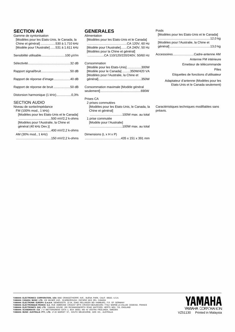
SECTION AMGamme de syntonisation
[Modèles pour les Etats-Unis, le Canada, laChine et général] .................530 à 1.710 kHz[Modèle pour l’Australie] ......531 à 1.611 kHz
Sensibilité utilisable...........................100 µV/m
Sélectivité................................................32 dB
Rapport signal/bruit .................................50 dB
Rapport de réponse d’image...................40 dB
Rapport de réponse de bruit ...................50 dB
Distorsion harmonique (1 kHz).................0,3%
SECTION AUDIONiveau de sortie/impédance
FM (100% mod., 1 kHz)[Modèles pour les Etats-Unis et le Canada].....................................500 mV/2,2 k-ohms[Modèles pour l’Australie, la Chine etgénéral (40 kHz Dev.)].....................................400 mV/2,2 k-ohms
AM (30% mod., 1 kHz)........................................150 mV/2,2 k-ohms
GENERALESAlimentation
[Modèles pour les Etats-Unis et le Canada].............................................CA 120V, 60 Hz[Modèle pour l’Australie].......CA 240V, 50 Hz[Modèles pour la Chine et général]...................CA 110/120/220/240V, 50/60 Hz
Consommation[Modèle pour les Etats-Unis] ................300W[Modèle pour le Canada] .........350W/420 VA[Modèles pour l’Australie, la Chine etgénéral].................................................350W
Consommation maximale [Modèle généralseulement]..............................................690W
Prises CA2 prises commutées
[Modèles pour les Etats-Unis, le Canada, laChine et général].....................................100W max. au total
1 prise commutée[Modèle pour l’Australie].....................................100W max. au total
Dimensions (L x H x P).........................................435 x 151 x 391 mm
Poids[Modèles pour les Etats-Unis et le Canada]...........................................................12,0 kg[Modèles pour l’Australie, la Chine etgénéral] ..............................................13,0 kg
Accessoires........................Cadre-antenne AM
Antenne FM intérieure
Emetteur de télécommande
Piles
Etiquettes de fonctions d’utilisateur
Adaptateur d’antenne (Modèles pour les Etats-Unis et le Canada seulement)
Caractéristiques techniques modifiables sanspréavis.
YAMAHA ELECTRONICS CORPORATION, USA 6660 ORANGETHORPE AVE., BUENA PARK, CALIF. 90620, U.S.A.YAMAHA CANADA MUSIC LTD. 135 MILNER AVE., SCARBOROUGH, ONTARIO M1S 3R1, CANADAYAMAHA ELECTRONIK EUROPA G.m.b.H. SIEMENSSTR. 22-34, 25462 RELLINGEN BEI HAMBURG, F.R. OF GERMANYYAMAHA ELECTRONIQUE FRANCE S.A. RUE AMBROISE CROIZAT BP70 CROISSY-BEAUBOURG 77312 MARNE-LA-VALLEE CEDEX02, FRANCEYAMAHA ELECTRONICS (UK) LTD. YAMAHA HOUSE, 200 RICKMANSWORTH ROAD WATFORD, HERTS WD1 7JS, ENGLANDYAMAHA SCANDINAVIA A.B. J A WETTERGRENS GATA 1, BOX 30053, 400 43 VÄSTRA FRÖLUNDA, SWEDENYAMAHA MUSIC AUSTRALIA PTY, LTD. 17-33 MARKET ST., SOUTH MELBOURNE, 3205 VIC., AUSTRALIA VZ51130 Printed in Malaysia