1m A 7m B 6m j 4m i s C - eng.auburn.edu
25
2.3. PLANE CURVILINEAR MOTION 11 Example 2.2 (similar to M&K 5ed 2/63) You are standing on top of the roof of a house. The house has a garage attached to the side of the house. You throw a baseball, releasing it from point A with a horizontal velocity. Find the necessary throwing speed so that the baseball just clears the corner of the garage, point B, and find the location of point C where the ball hits the ground. 4m 6m 7m 1m A B C s v A i j ^ ^ We first define our coordinate system choosing the point on the ground where the garage joins the house as the origin. Next, we write the given information in vector form. r A =8 ˆ j (2.14) v A = v A ˆ i (2.15) a = −9.81 ˆ j (2.16) Let’s say it takes t B seconds for the ball to travel from A to B. At point B, the position vector is r B =6 ˆ i +4 ˆ j . We can substitute these vectors into the constant-acceleration equation. r B = r A + v A t B + 1 2 at 2 B (2.17) 6 ˆ i +4 ˆ j =8 ˆ j + v A t B ˆ i − 9.81 2 t 2 B ˆ j (2.18) Next, we extract the scalar equations to get two equations for the two unknowns: v A and t B . 6= v A t B (2.19) 4=8 − 9.81 2 t 2 B Solving for the unknowns: t B =0.903 s and v A =6.64 m/s.
Transcript of 1m A 7m B 6m j 4m i s C - eng.auburn.edu

2.3. PLANE CURVILINEAR MOTION 11
Example 2.2 (similar to M&K 5ed 2/63)You are standing on top of the roof of a house. The house has a garage attachedto the side of the house. You throw a baseball, releasing it from point A with ahorizontal velocity. Find the necessary throwing speed so that the baseball justclears the corner of the garage, point B, and find the location of point C wherethe ball hits the ground.
4m
6m7m
1m A
B
Cs
vA
ij
^
^
We first define our coordinate system choosing the point on the ground wherethe garage joins the house as the origin. Next, we write the given informationin vector form.
rA = 8j (2.14)
vA = vAi (2.15)
a = −9.81j (2.16)
Let’s say it takes tB seconds for the ball to travel from A to B. At point B,the position vector is rB = 6i + 4j. We can substitute these vectors into theconstant-acceleration equation.
rB = rA + vAtB +12at2B (2.17)
6i + 4j = 8j + vAtB i − 9.812
t2B j (2.18)
Next, we extract the scalar equations to get two equations for the two unknowns:vA and tB.
6 = vAtB (2.19)
4 = 8 − 9.812
t2B
Solving for the unknowns: tB = 0.903 s and vA = 6.64 m/s.
12 CHAPTER 2. PARTICLE KINEMATICS
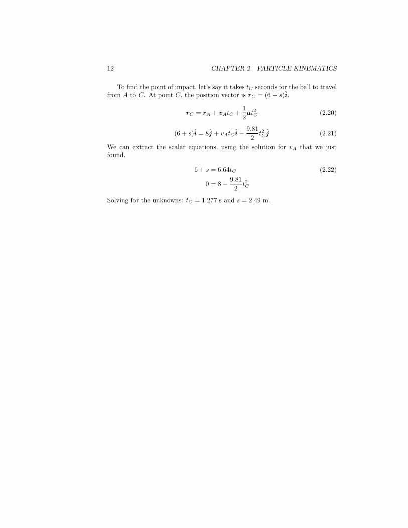
To find the point of impact, let’s say it takes tC seconds for the ball to travelfrom A to C. At point C, the position vector is rC = (6 + s)i.
rC = rA + vAtC +12at2C (2.20)
(6 + s)i = 8j + vAtC i − 9.812
t2C j (2.21)
We can extract the scalar equations, using the solution for vA that we justfound.
6 + s = 6.64tC (2.22)
0 = 8 − 9.812
t2C
Solving for the unknowns: tC = 1.277 s and s = 2.49 m.
2.3. PLANE CURVILINEAR MOTION 17
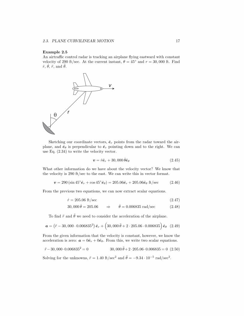
Example 2.5An airtraffic control radar is tracking an airplane flying eastward with constantvelocity of 290 ft/sec. At the current instant, θ = 45◦ and r = 30, 000 ft. Findr, θ, r, and θ.
θ r
v
Sketching our coordinate vectors, er points from the radar toward the air-plane, and eθ is perpendicular to er pointing down and to the right. We canuse Eq. (2.34) to write the velocity vector.
v = rer + 30, 000 θeθ (2.45)
What other information do we have about the velocity vector? We know thatthe velocity is 290 ft/sec to the east. We can write this in vector format.
v = 290 (sin 45◦er + cos 45◦eθ) = 205.06er + 205.06eθ ft/sec (2.46)
From the previous two equations, we can now extract scalar equations.
r = 205.06 ft/sec (2.47)
30, 000 θ = 205.06 ⇒ θ = 0.006835 rad/sec (2.48)
To find r and θ we need to consider the acceleration of the airplane.
a =(r − 30, 000 · 0.0068352
)er +
(30, 000 θ + 2 · 205.06 · 0.006835
)eθ (2.49)
From the given information that the velocity is constant, however, we know theacceleration is zero: a = 0er + 0eθ. From this, we write two scalar equations.
r−30, 000 ·0.0068352 = 0 30, 000 θ+2 ·205.06 ·0.006835 = 0 (2.50)
Solving for the unknowns, r = 1.40 ft/sec2 and θ = −9.34 · 10−5 rad/sec2.

20 CHAPTER 2. PARTICLE KINEMATICS
Example 2.6A bullet is fired with a velocity of 1000 m/s upward at an angle of 10◦. Thebullet’s acceleration has two components: gravity g = 9.81m/s2 and aerody-namic drag d = 1160 m/s2 which acts opposite the velocity. Find the radius ofcurvature of the bullet’s trajectory and the rate at which the bullet’s speed ischanging.
10o
v
g
d
Starting with sketching the coordinate vectors, et is parallel to the velocitypointing to the right and slightly up, and en points down and slightly to theright. Based on our kinematic expression, we can write the acceleration vectoras the following.
a = vet +10002
ρen (2.55)
From the given information, we know that the acceleration vector is composedof two physical components. The drag component acts opposite the velocityvector, in the −et direction. The gravity component acts straight down withcomponents in both directions.
a = −1160et + 9.81 (cos 10◦en − sin 10◦et) (2.56)
From these two expressions for the acceleration vector, we extract the scalarequations.
v = −1160− 9.81 sin10◦ (2.57)
10002
ρ= 9.81 cos10◦ (2.58)
Solving for the unknowns, v = −1162 m/s2 and ρ = 103, 500 m = 103.5 km.

32 CHAPTER 3. PARTICLE KINETICS
3.3 Example Problems
Example 3.1Consider a fuzzy die hanging on a cord from the rearview mirror of a car. Thecar is decelerating at 0.2g. Find the steady-state angle the cord makes with thevertical.
θi^
j^
1. Kinematics - Let’s use the coordinate vectors indicated in the diagram. In thesteady-state condition, the die’s acceleration is the same as the car: a = 0.2gi.2. FBD - In sketching your own FBD, the only forces acting on the die aregravity, mg, and the tension in the cord, T . The resulting force expression isΣF = T sin θi + (T cos θ − mg)j.3. N2L - Substituting into Newton’s second law:
T sin θi + (T cos θ − mg)j = 0.2mgi (3.5)
Extracting scalar equations of motion:
T sin θ = 0.2mg (3.6)T cos θ − mg = 0
From these equations, solve for θ.
tan θ = 0.2 ⇒ θ = 11.31◦ (3.7)

34 CHAPTER 3. PARTICLE KINETICS
Example 3.3The rod rotates about B in the horizontal plane with a constant angular rateθ = 0.05 rad/s. Collar A has a mass of 0.3 kg and slides along the rod withoutfriction. At the current instant, the collar is at a radius of r = 0.15 m and issliding along the rod with r = 0.2 m/s. Find the value of r and the force exertedon the collar by the bar.
0.15 m
θ = 0.05 rad/s.
A
B
1. Kinematics - Choosing polar coordinate vectors, er points along the rod, andeθ points up and to the left. Using the given information, we can write anexpression for the acceleration vector.
a =(r − 0.15 · 0.052
)er + (0 + 2 · 0.2 · 0.05) eθ (3.13)
=(r − 3.75 · 10−4
)er + 0.02eθ
2. FBD - In sketching your own FBD, the rod exerts a force N on the collar.The force is perpendicular to the rod, but we’re not sure if it’s in the positive ornegative eθ direction. So for now, let’s just guess it’s in the positive eθ direction.
ΣF = N eθ (3.14)
Of course, gravity is also acting on the collar. But since we’re focused on themotion in the horizontal plane, we can neglect gravity.3. N2L - Note that the collar has a mass of 0.3 kg.
N eθ = 0.3[(
r − 3.75 · 10−4)er + 0.02eθ
](3.15)
Extracting scalar equations of motion:
0 = 0.3(r − 3.75 · 10−4
)(3.16)
N = 0.3 · 0.02
From these equations, r = 3.75 · 10−4 m/s2 and N = 0.006 N. We had guessedthat N acts in the positive eθ direction. Since we got a positive answer for N ,this guess must have been correct.

48 CHAPTER 3. PARTICLE KINETICS
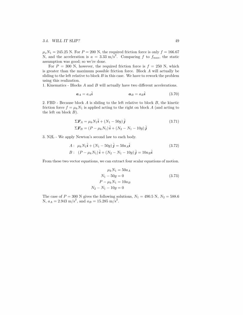
Example 3.11Block A has a mass of 50 kg, and block B has a mass of 10 kg. The coefficientsof friction between blocks A and B are μs = 0.5 and μk = 0.3. Neglect anyfriction between block B and the ground. Find the acceleration of each blockwhen a force of (a) P = 200 N and (b) P = 300 N is applied to block B.
P
A
B
In this problem, we need to analyze the motion of both blocks A and B.We’ll start by assuming static friction between the blocks.1. Kinematics - Rectangular coordinates with i pointing to the right and jpointing up will be convenient for this problem. Under static friction, both Aand B have the same acceleration, but the magnitude is unknown.
aA = aB = ai (3.65)
Note, the static-friction assumption does not mean the blocks have zero accel-eration!2. FBD - The forces acting on A are its weight, a normal force N1 from B, andthe friction force f from B. Let’s guess f pushes A to the right.
ΣFA = f i + (N1 − 50g) j (3.66)
Two of the forces acting on B are its weight and a normal force N2 from theground. Also, the two forces N1 and f that B exerts on A must be exerted inequal magnitude but opposite direction by A on B. And of course, there is theapplied force P .
ΣFB = (P − f) i + (N2 − N1 − 10g) j (3.67)
3. N2L - We apply Newton’s second law to each body.
A : f i + (N1 − 50g) j = 50ai (3.68)
B : (P − f) i + (N2 − N1 − 10g) j = 10ai
From these two vector equations, we can extract four scalar equations of motion.
f = 50a
N1 − 50g = 0 (3.69)P − f = 10a
N2 − N1 − 10g = 0
Solving for the unknowns, a = P/60, f = 5P/6, N1 = 490.5 N, and N2 = 588.6N. From this solution, the maximum possible static friction force is fmax =
3.4. WILL IT SLIP? 49
μsN1 = 245.25 N. For P = 200 N, the required friction force is only f = 166.67N, and the acceleration is a = 3.33 m/s2. Comparing f to fmax, the staticassumption was good; so we’re done.
For P = 300 N, however, the required friction force is f = 250 N, whichis greater than the maximum possible friction force. Block A will actually besliding to the left relative to block B in this case. We have to rework the problemusing this realization.1. Kinematics - Blocks A and B will actually have two different accelerations.
aA = aAi aB = aB i (3.70)
2. FBD - Because block A is sliding to the left relative to block B, the kineticfriction force f = μkN1 is applied acting to the right on block A (and acting tothe left on block B).
ΣFA = μkN1i + (N1 − 50g) j (3.71)
ΣFB = (P − μkN1) i + (N2 − N1 − 10g) j
3. N2L - We apply Newton’s second law to each body.
A : μkN1i + (N1 − 50g) j = 50aAi (3.72)
B : (P − μkN1) i + (N2 − N1 − 10g) j = 10aB i
From these two vector equations, we can extract four scalar equations of motion.
μkN1 = 50aA
N1 − 50g = 0 (3.73)P − μkN1 = 10aB
N2 − N1 − 10g = 0
The case of P = 300 N gives the following solutions, N1 = 490.5 N, N2 = 588.6N, aA = 2.943 m/s2, and aB = 15.285 m/s2.

6.1. WORK & ENERGY 123
Example 6.2The 30 kg block slides 5 m down the ramp from A to B. The coefficient ofkinetic friction between the block and the ramp is 0.3. The speed of the blockat A is 4 m/s down the ramp. Find the speed when the block passes B.
5 m
A
B
20o
We’ll take a look at working this problem using both forms of the work-energy principle. First, the initial kinetic energy of the crate is TA = 1
230 · 42 =240 J. Next, we need to consider the work done on the crate as it travels theten meters from A to B. The forces acting on the crate are the normal andfriction forces from the chute and weight due to gravity. The normal force actsperpendicular to the motion of the crate, so it does zero work. The frictionforce acts opposite the motion, so it does negative work. The friction forceis related to the normal force, so we still need to use Newton’s second law tofind the normal force. The gravitational force has components parallel andperpendicular to the chute, but only the component parallel to the chute doeswork.
UA→B = −5f + 5mg sin 20◦ = −5μkN + 5mg sin 20◦ (6.10)= −5μkmg cos 20◦ + 5mg sin 20◦ = 88.455 J
The kinetic energy at B is TB = 1230v2
B. Applying the work-energy principle:
TA + UA→B = TB
240 + 88.455 =1230v2
B (6.11)
vB = 4.68 m/s
Now, let’s work this problem using the potential-energy form of the work-energy principle. In writing the potential energy, let’s define B as having aheight of zero. Therefore, the potential energy at A is VA = mghA = 30 ·9.81 · 5 sin 20◦ = 503.3 J, and the potential energy at B is VB = mghB = 0.The friction is the only nonpotential force that does work: UNP,A→B = −5f =−5μkN = −5μkmg cos 20◦ = −414.8 J.
TA + VA + UNP,A→B = TB + VB
240 + 503.3− 414.8 =1230v2
B (6.12)
vB = 4.68 m/s
124 CHAPTER 6. ALTERNATIVE CONCEPTS
Whether we think about the mg sin 20◦ component of weight doing work overthe 5 m distance, or think about the weight mg causing a change in potentialenergy due to the 5 sin 20◦ height change, it’s two sides of the same coin.

6.1. WORK & ENERGY 125
Example 6.3A 5 lb slider is released from rest at the top of the smooth rod. Find themaximum compression of the 20 lb/in spring.
3 ft
The slider is released from rest at the initial point, and therefore has zerokinetic energy: T1 = 0. Defining the height of the spring in its undeformedconfiguration as the reference height, the slider has a potential energy of V1 =mgh = 5 · 3 = 15 ft · lb.
Since the rod is smooth, the only nonpotential force acting on the slider isthe normal force from the rod, but it does no work: UNP = 0. Because nononpotential forces do work, it really doesn’t matter what happens to the sliderbetween the point of release and the point of maximum compression.
The maximum compression of the spring will come, at the instant whenthe slider will again have zero kinetic energy: T2 = 0. At this instant therewill be elastic potential energy in the spring, and the slider will have negativegravitational potential energy, since the compression in the spring will actuallydrop the slider below the reference height: V2 = 1
2kx2 −mgx = 1220 · 12x2 − 5x,
where x is the spring compression in feet. Applying the work-energy principle:
T1 + V1 + UNP = T2 + V2 (6.13)
15 = 120x2 − 5x
x =924
or − 13
ft = 4.5 or − 4 in
The quadratic equation for x gives two answers: one positive and one negative.The positive answer corresponds with compression of the spring. The negativeanswer corresponds represents if the collar had bounced back up the rod withthe spring attached, stretching it. The work-energy principle can only tell usthat these two solutions both have the correct amount of energy. It’s up to us torecognize that the collar actually compresses the spring with the answer x = 4.5in.

138 CHAPTER 6. ALTERNATIVE CONCEPTS
Example 6.9 (M&K 6ed 3/230)The small spheres, which have the masses and initial velocities shown in thefigure, strike and become attached to the spiked ends of the rod, which is freelypivoted at fixed point O and is initially at rest. Determine the angular velocityω of the assembly after impact. Neglect the mass of the rod.
2m
m3v
v
L
L
O
Define time 1 before the spheres impact the rod, and time 2 after the entireassembly is rotating about O. Define k pointing up from the table shown inthe diagram. At time 1, the 2m sphere has an angular momentum about O of2mvLk, and the m sphere has an angular momentum about O of 3mvLk.
During the collision, forces act between each sphere and the spikes, and therod may also experience some reaction forces at O. If we consider the systemconsisting of the two spheres and the rod, then the interaction forces betweenthe spheres and the spikes impart zero net angular impulse on the system. Thereaction forces at O generate zero moments about O, and therefore also impartzero net angular impulse about O. Once the system starts rotating about O,there must be some tension in the rod pulling the spheres through their newcircular trajectories. But these forces also generate zero moment about O.Therefore, from time 1 to time 2, there is zero net angular impulse on thesystem.
At time 2, both spheres have a speed of ωL. The angular momentum aboutO of the 2m sphere is now 2m(ωL)Lk, and the angular momentum about O ofthe m sphere is m(ωL)Lk. Assume the rod has negligible mass so we don’t haveto worry about its angular momentum. Substitute all of the above informationinto the angular momentum-impulse principle.
hO,1 = hO,2 ⇒ 2mvLk + 3mvLk = 2m(ωL)Lk + m(ωL)Lk
5mvL = 3mωL2 (6.43)
ω =5v
3L

58 CHAPTER 4. PLANAR RIGID-BODY KINEMATICS
Example 4.3The end B of the bar moves in a horizontal channel to the right at a constantspeed of 3 m/s. The end A of the bar moves in a vertical channel. At theinstant when θ = 30◦, find the angular velocity and angular acceleration of thebar. Also, find the velocity and acceleration of A.
θ
2 m
B
A
A. Define i pointing to the right, j pointing up, and k pointing out of the page.B. The magnitude of the angular velocity is unknown, but it’s clear it will be inthe positive k direction: ω = ωk. The magnitude of the angular acceleration isunknown, and it’s not even clear what the direction will be. Let’s guess α = αk.C. Let’s use B as a reference point: vB = 3i and aB = 0. We also need theposition of A relative to B.
rA/B = 2(cos 30◦i + sin 30◦j
)=
√3i + j (4.15)
D. From this we can calculate the velocity and acceleration of A.
vA = vB + ω × rA/B
= 3i + ωk ×(√
3i + j)
(4.16)
= (3 − ω) i +√
3ωj
aA = aB + α × rA/B + ω × (ω × rA/B
)= αk ×
(√3i + j
)+ ωk ×
(−ωi +
√3ωj
)(4.17)
= −(α +
√3ω2
)i +
(√3α − ω2
)j
Physically, we know the velocity and acceleration of A are in the vertical direc-tion: vA = vAj and aA = aAj. From these two vector equations, we get fourscalar equations.
0 = 3 − ω
vA =√
3ω (4.18)
0 = α +√
3ω2
aA =√
3α − ω2
Solving for the unknowns: ω = 3 rad/s, α = −9√
3 rad/s2, vA = 3√
3 m/s,aA = −36 m/s2.

4.4. ROLLING WHEELS 63
4.4 Rolling Wheels
Rolling wheels are one type of rigid-body kinematics problem.
Example 4.6Consider a wheel that is rolling without slipping. This means that the pointof contact (the part of the wheel that is touching the ground) has the samevelocity as the ground, i.e. zero. It doesn’t mean that the point of contact haszero acceleration. If we come back an instant later, that same piece of the wheelwill no longer be the point of contact and will have nonzero velocity.
r
O
C
ωα
i^
j^
Let’s find the velocity of O, the center of the wheel.A. The i and j directions are shown in the diagram. To keep a right-handedcoordinate system, k points out of the page.B. Based on the indicated directions, ω = −ωk and α = −αk.C. We can use C as a reference point, since we know its velocity: vC = 0. Theposition of O relative to C is rO/C = rj.D. From this we can calculate the velocity of O.
vO = vC + ω × rO/C = −ωk × j = ωri (4.29)
Using calculus, we can find the acceleration of O.
aO =ddt
(vO) = αri (4.30)
For good measure, let’s find the acceleration of C. Steps A and B don’t change.C. Since we found the acceleration of O, we can now use it as a reference point.The position of C relative to O is rC/O = −rj.D. Calculate the acceleration of C.
aC = aO + α × rC/O + ω × (ω × rC/O
)= αri +
(−αk
)×(−rj
)+(−ωk
)×[(
−ωk)×(−rj
)](4.31)
= ω2rj
Thus the point of contact is accelerating up off the ground. Now that the we’vefound the velocity and acceleration of the center and point of contact of a wheelrolling without slipping, we can use these results in other problems.

4.5. MECHANISMS 67
4.5 Mechanisms
Mechanisms made up of multiple rigid bodies are another type of rigid-bodykinematics problem. Each body has its own angular velocity and angular accel-eration. We’ll apply the same steps to these problems, just working from oneend of the mechanism to the other. In doing this, we take advantage of the factthat a joint is a point on both of the bodies that it connects.
Example 4.9 (Similar to M&K 5ed 5/128)Consider the mechanism made of links OB and BA. Link OB has length 1 m,and link AB has length
√2 m. Link OB is rotating counter clockwise with a
constant angular velocity of 2 rad/s. Point A rides in a vertical channel and atthe current instant is 1 m to the right of point O. We want to find the angularvelocity and angular acceleration of link AB.
O
B
A
2 rad/s
i
j^
^
A. The coordinate vectors are shown in the diagram.B. The angular velocity and angular acceleration of OB are known, but theangular velocity and angular acceleration of AB are unknown.
ωOB = 2k ωAB = ωABk
αOB = 0 αAB = αABk(4.43)
C. First, we use point O as a reference point to investigate point B.
vO = aO = 0 rB/O = 1j (4.44)
D. From the above information, we can find the velocity and acceleration ofpoint B.
vB = vO + ωOB × rB/O = 2k × 1j = −2i (4.45)
aB = aO + αOB × rB/O + ωOB × (ωOB × rB/O
)= 2k ×
(2k × 1j
)= 2k ×−2i (4.46)
= −4j

68 CHAPTER 4. PLANAR RIGID-BODY KINEMATICS
C. Now, we can use point B as a reference point to investigate point A.
rA/B = 1i − 1j (4.47)
D. From the above information, we can find the velocity and acceleration ofpoint A.
vA = vB + ωAB × rA/B
= −2i + ωABk ×(1i − 1j
)(4.48)
= (ωAB − 2) i + ωAB j
aA = aB + αAB × rA/B + ωAB × (ωAB × rA/B
)= −4j + αAB k ×
(1i − 1j
)+ ωABk ×
(ωAB i + ωAB j
)(4.49)
=(αAB − ω2
AB
)i +
(αAB + ω2
AB − 4)j
However, we know the velocity and acceleration of A must be in the verticaldirection: vA = vAj and aA = aAj.
ωAB − 2 = 0ωAB = vA (4.50)
αAB − ω2AB = 0
αAB + ω2AB − 4 = aA
From these scalar equations, we find ωAB = 2 rad/s, vA = 2 m/s, αAB =4 rad/s2, and aA = 4 m/s2.
76 CHAPTER 4. PLANAR RIGID-BODY KINEMATICS
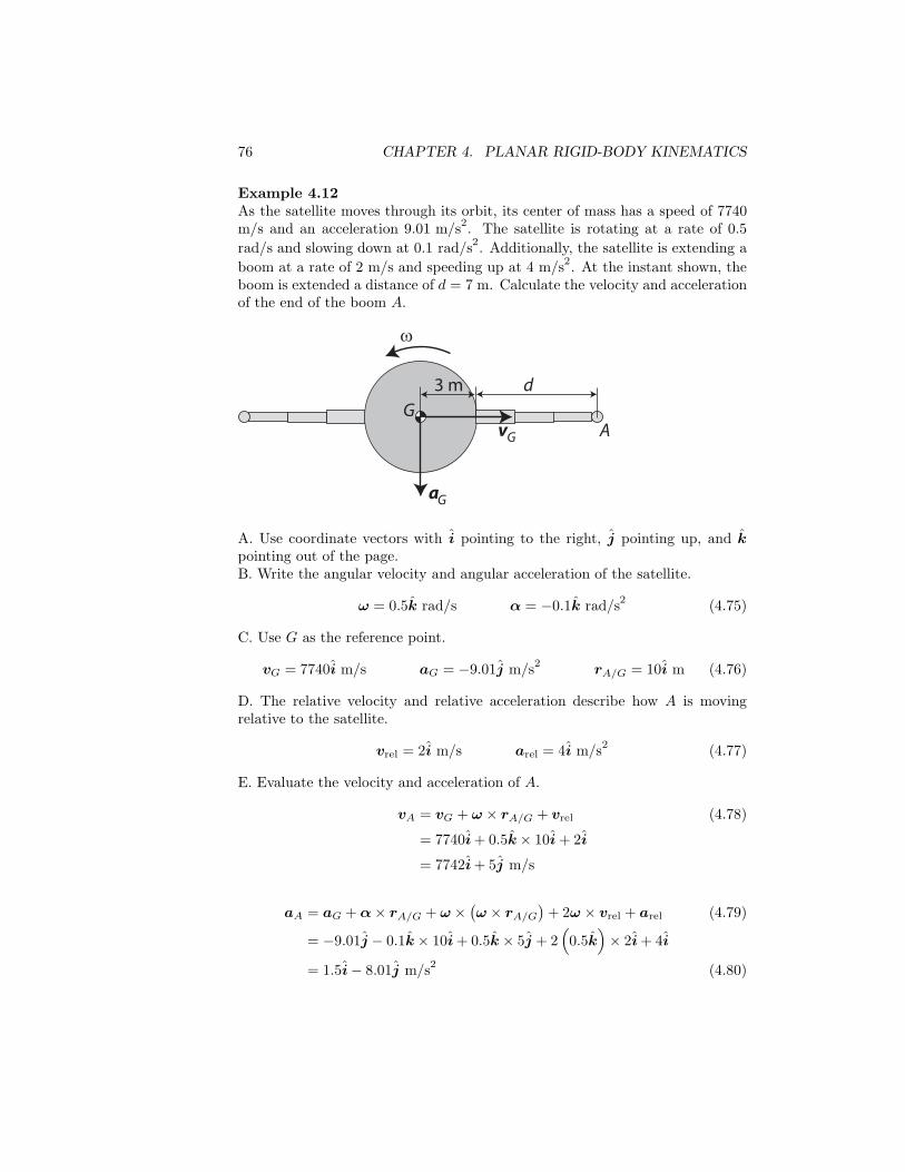
Example 4.12As the satellite moves through its orbit, its center of mass has a speed of 7740m/s and an acceleration 9.01 m/s2. The satellite is rotating at a rate of 0.5rad/s and slowing down at 0.1 rad/s2. Additionally, the satellite is extending aboom at a rate of 2 m/s and speeding up at 4 m/s2. At the instant shown, theboom is extended a distance of d = 7 m. Calculate the velocity and accelerationof the end of the boom A.
3 m d
aG
vG
ω
GA
A. Use coordinate vectors with i pointing to the right, j pointing up, and kpointing out of the page.B. Write the angular velocity and angular acceleration of the satellite.
ω = 0.5k rad/s α = −0.1k rad/s2 (4.75)
C. Use G as the reference point.
vG = 7740i m/s aG = −9.01j m/s2 rA/G = 10i m (4.76)
D. The relative velocity and relative acceleration describe how A is movingrelative to the satellite.
vrel = 2i m/s arel = 4i m/s2 (4.77)
E. Evaluate the velocity and acceleration of A.
vA = vG + ω × rA/G + vrel (4.78)
= 7740i + 0.5k × 10i + 2i
= 7742i + 5j m/s
aA = aG + α × rA/G + ω × (ω × rA/G
)+ 2ω × vrel + arel (4.79)
= −9.01j − 0.1k × 10i + 0.5k × 5j + 2(0.5k
)× 2i + 4i
= 1.5i − 8.01j m/s2 (4.80)

5.4. EXAMPLE PROBLEMS 91
5.4 Example Problems
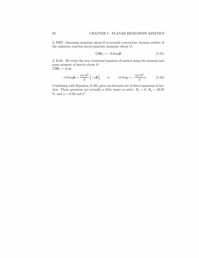
Example 5.4 (M&K 5ed 6/33)The uniform 20 kg slender bar is pivoted at O and swings freely in the verticalplane. If the bar is released from rest in the horizontal position, calculate theinitial values of the angular acceleration and the reaction forces at O.
O1.6 m
1. Kinematics - Use rectangular coordinates with i to the right, j up, and kout of the page. As released from rest the angular velocity is zero, but we canexpect the angular acceleration to be clockwise: ω = 0 and α = −αk. Thecenter of mass G is in the middle of the bar. We can use point O as a referencepoint to find the acceleration of G.
aO = 0 rG/O = 0.8i (5.25)
aG = aO + α × rG/O + ω × (ω × rG/O
)(5.26)
= −αk × 0.8i = −0.8αj
2. FBD - Drawing your own FBD, the weight mg acts downward through thecenter of mass, and let’s guess the reaction forces Rx and Ry act to the rightand up, respectively, at O.
ΣF = Rxi + (Ry − mg) j (5.27)
We can sum moments about either G or O. We’ll work it both ways, but let’sstart with G.
ΣMG = −0.8Ryk (5.28)
3. EoM - Substitute the above results into the equations of motion.ΣF = maG:
Rxi + (Ry − mg) j = m(−0.8αj
)⇒ Rx = 0
Ry − mg = −0.8mα(5.29)
ΣMG = IGα:
−0.8Ryk =m1.62
12
(−αk
)⇒ −0.8Ry = −m1.62
12α (5.30)
Solving for the three equations of motion for the unknowns, Rx = 0, Ry = 49.05N, and α = 9.20 rad/s2.
Now, let’s go back and work the problem summing moment about O, justto show that we get the same answer.
92 CHAPTER 5. PLANAR RIGID-BODY KINETICS
2. FBD - Summing moments about O is actually convenient, because neither ofthe unknown reaction forces generate moments about O.
ΣMO = −0.8mgk (5.31)
3. EoM - We write the new rotational equation of motion using the moment andmass moment of inertia about O.ΣMO = IOα:
−0.8mgk =m1.62
3
(−αk
)⇒ −0.8mg = −m1.62
3α (5.32)
Combining with Equation (5.29), gives an alternate set of three equations of mo-tion. These questions are actually a little easier to solve: Rx = 0, Ry = 49.05N, and α = 9.20 rad/s2.

5.4. EXAMPLE PROBLEMS 99
Example 5.9Block A is attached by a cable to a pulley whose center is the fixed axis O.The block has a weight of 30 lbs. The pulley has a weight of 50 lbs, an innerradius of 2 ft, and a radius of gyration of 1.75 ft. Find the acceleration of A, theangular acceleration of the pulley, and the tension in the cable, (a) assumingthe pulley axis has zero friction, and (b) a 10 ft·lb moment due to friction actsat the pulley axis.
O
A
2 ft
In particle kinetics, we looked at many problems involving pulleys. But inthose previous problems, we implicitly assumed that the pulleys had negligiblemass. In this problem, the dynamics of the large, massive pulley needs to beaddressed, along with the block. Let’s do part (a) first.1. Kinematics - Use rectangular coordinates with i to the right, j up, and kout of the page. The angular acceleration of the pulley is going to be in theclockwise direction: α = −αk. Point O is the center of mass of the pulley andhas zero acceleration: aO = 0. We don’t have to worry about any rotation ofthe block, but the acceleration is aA = −2αj.2. FBD - We need to draw a FBD for each body. The pulley has the tension ineach cable, reaction forces at O, and weight acting on it.
ΣFP = Rxi + (Ry − T − 50) j (5.56)
Since O is the center of mass of the pulley, it is our only choice to sum momentsabout.
ΣMO = −2T k (5.57)
We also need to sum the forces acting on the block.
ΣFA = (T − 30) j (5.58)

100 CHAPTER 5. PLANAR RIGID-BODY KINETICS
3. EoM - Substituting into the equations of motion.ΣFP = mP aO:
Rxi + (Ry − T − 50) j = 0 ⇒ Rx = 0Ry − T − 50 = 0 (5.59)
ΣMO = IOα:
−2T k =(
5032.2
· 1.752
)(−αk
)⇒ 2T =
153.12532.2
α (5.60)
ΣFA = mAaA:
(T − 30) j =30
32.2
(−2αj
)⇒ T − 30 = − 60
32.2α (5.61)
Solving these four equations, α = 7.07 rad/sec2 and T = 16.8 lb. This gives theacceleration of A as 14.2 ft/sec2.
For part (b), the only change we need to make is to include the pure momentdue to friction in ΣMO.2. FBD - The friction moment acts in the counter clockwise direction, resistingthe pulley’s angular acceleration.
ΣMO = (−2T + 10) k (5.62)
3. EoM - Only the rotational equation changes.ΣMO = IOα:
(−2T + 10) k =(
5032.2
· 1.752
)(−αk
)⇒ 2T − 10 =
153.12532.2
α (5.63)
Solving the new set of equations gives α = 5.89 rad/sec2 and T = 19.0 lb, givingthe acceleration of A as 11.8 ft/sec2.
6.1. WORK & ENERGY 131
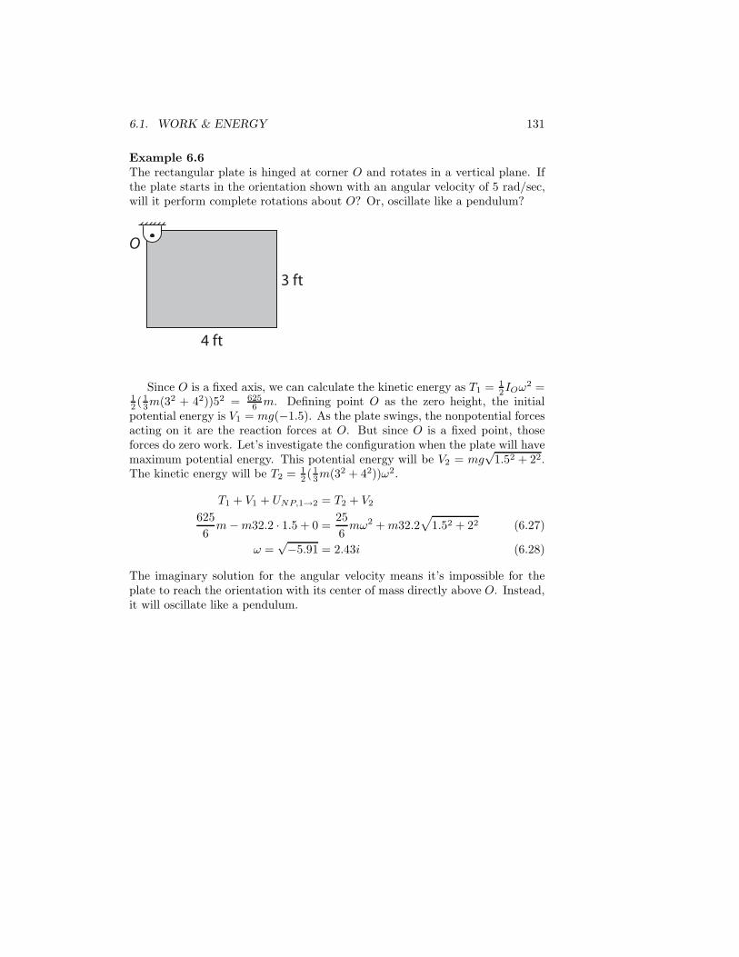
Example 6.6The rectangular plate is hinged at corner O and rotates in a vertical plane. Ifthe plate starts in the orientation shown with an angular velocity of 5 rad/sec,will it perform complete rotations about O? Or, oscillate like a pendulum?
3 ft
O
4 ft
Since O is a fixed axis, we can calculate the kinetic energy as T1 = 12IOω2 =
12 (1
3m(32 + 42))52 = 6256 m. Defining point O as the zero height, the initial
potential energy is V1 = mg(−1.5). As the plate swings, the nonpotential forcesacting on it are the reaction forces at O. But since O is a fixed point, thoseforces do zero work. Let’s investigate the configuration when the plate will havemaximum potential energy. This potential energy will be V2 = mg
√1.52 + 22.
The kinetic energy will be T2 = 12 (1
3m(32 + 42))ω2.
T1 + V1 + UNP,1→2 = T2 + V2
6256
m − m32.2 · 1.5 + 0 =256
mω2 + m32.2√
1.52 + 22 (6.27)
ω =√−5.91 = 2.43i (6.28)
The imaginary solution for the angular velocity means it’s impossible for theplate to reach the orientation with its center of mass directly above O. Instead,it will oscillate like a pendulum.

6.2. IMPULSE & MOMENTUM 141
Example 6.10A platform is resting on a smooth surface, and a cylinder is resting on theplatform. Both the platform and cylinder have weights of 50 lbs. A 10 lb forceis then applied to the platform for 10 seconds. During this period the cylinderis observed to roll without slip on the platform. Find the speeds of the platformand the center of the cylinder at the end of the 10 second period.
A10 lb
r
Define i pointing to the right, j pointing up, and k pointing out of the page.Consider the system consisting of the platform and cylinder. Initially, bothstart at rest, so the system has zero linear momentum. Over 10 seconds, the10 pound force applies 100 lb·sec of impulse. At the end of the 10 seconds, theplatform will have some velocity vP i, and the center of the cylinder will have avelocity vC i. Using this information, we can write the linear impulse-momentumprinciple.
p1 +∫ 10
0
ΣFdt = p2
0i + 100i =50
32.2vP i +
5032.2
vC i (6.51)
50 (vP + vC) = 3220 (6.52)
Next, let’s look at the angular momentum of the cylinder by itself. Specif-ically, let’s look at the angular momentum about the fixed reference point Alabeled in the diagram. Initially, the cylinder has zero angular momentum aboutA. During the 10 second period, the forces acting on the cylinder are weightdue to gravity and normal & friction forces exerted by the platform. The an-gular impulses about A due to the weight and normal forces cancel each otherout. The friction force exerts zero moment about A and therefore zero angularimpulse about A. At the end of the end of the 10 seconds, the cylinder’s angularmomentum about A will be related to the moment of its linear momentum andits angular velocity ω = ωk. Since the cylinder is rolling without slipping on themoving platform, the velocity of its center and its angular velocity are linked.
vC = vP + ω × rC/P (6.53)
vC i = vP i + ωk × rj = (vP − ωr) i
ω =vP − vC
r(6.54)

142 CHAPTER 6. ALTERNATIVE CONCEPTS
hA,1 +∫ 10
0
ΣMAdt = hA,2
0k + 0k = − 5032.2
vcrk +12· 5032.2
r2ωk (6.55)
0 = − 5032.2
vcr +25
32.2r (vP − vC)
25vP − 75vC = 0 (6.56)
Solving these two equations gives vc = 16.1 ft/sec and vp = 48.3 ft/sec. We wereable to find these solutions without ever calculating the friction force betweenthe platform and cylinder.
Example 6.11A rectangular block is sliding across a smooth surface with a speed of 1.2 m/s.It hits a small curb on the surface, causing it to rotate about the lower rightcorner. (Neglect the height of the curb.) Find the angular velocity of the blockimmediately after it hits the curb.
6 kg
0.2 m
0.3 m
Label the curb as point C, and define k pointing out of the page. The initialangular momentum of the block about C is hC = −6 · 1.2 · 0.15k = −1.08kN·m·s. During the impact reaction forces at C act on the block. But theygenerate zero moment about C, and therefore zero angular impulse about C.After the impact, the block is rotating about C.
Using this information, we can write the angular impulse-momentum prin-ciple about C.
hC,1 = hC,2
−1.08k =(
136(0.22 + 0.32
))(−ωk)
(6.57)
ω = 4.15 rad/sec

Formulas
atvv += 0
200 2
1 attvrr ++=
( )0
20
2 2 ssavv −+=
rryx ejir ˆˆˆ =+=
tr vrryx eeejiv ˆˆˆˆˆ =+=+= θθ
( ) ( )
nt
r
vv
rrrr
yx
ee
ee
jia
ˆˆ
ˆ2ˆ
ˆˆ
2
2
ρ
θθθ θ
+=
++−=
+=
BABA /rrr +=
BABA /vvv +=
BABA /aaa +=
relBABA vrωvv +×+= /
Nf ss µ≤
Nf kk µ=
2mdII GC +=
2CI cmk=
GmaF =Σ
αM CC I=Σ
∫ •=→
2
121 rF dU
2
particle 21 mvT =
222
body 21
21
21 ωω OGG IImvT =+=
2221,np11 VTUVT +=++ →
vp m=particle
Gmvp =body
12
2
1d ppF −=Σ∫ t
vrh mC ×=particle,
ωvrh GGCGC Im +×= /body,
ωh GG I=body,
ωh OO I=body,
( ) relrelBABABA avωrωωrαaa +×+××+×+= 2//
22 m/s 819ft/sec 232 .. ==g
1,2,
2
1d CCC t hhM −=Σ∫