19981218 040 IMPACT Instrumentation, Inc., Continous & Intermittent Oropharyngeal/Tracheal Suction,...
18
AFRL-HE-BR-TR-1998-0018 UNITED STATES AIR FORCE "RESEARCH LABORATORY TESTING AND EVALUATION OF THE IMPACT INSTRUMENTATION, INC. 326M INTERMITTENTI CONTINUOUS OROPHARYNGEAL/ TRACHEAL SUCTION APPARATUS Butch 0. Blake, MSgt, USAF HUMAN EFFECTIVENESS DIRECTORATE FLIGHT STRESS PROTECTION DIVISION SYSTEMS RESEARCH BRANCH 2504 Gillingham Drive, Suite 25 Brooks AFB, Texas 78235-5104 June 1998 19981218 040 Approved for public release; distribution is unlimited.
Transcript of 19981218 040 IMPACT Instrumentation, Inc., Continous & Intermittent Oropharyngeal/Tracheal Suction,...
AFRL-HE-BR-TR-1998-0018
UNITED STATES AIR FORCE"RESEARCH LABORATORY
TESTING AND EVALUATION OF THEIMPACT INSTRUMENTATION, INC.
326M INTERMITTENTICONTINUOUS OROPHARYNGEAL/TRACHEAL SUCTION APPARATUS
Butch 0. Blake, MSgt, USAF
HUMAN EFFECTIVENESS DIRECTORATEFLIGHT STRESS PROTECTION DIVISION
SYSTEMS RESEARCH BRANCH2504 Gillingham Drive, Suite 25Brooks AFB, Texas 78235-5104
June 1998
19981218 040Approved for public release; distribution is unlimited.
NOTICES
This final technical report was submitted by personnel of the Systems Research Branch,Crew Technology Division, Air Force Research Laboratory, AFMC, Brooks Air Force Base,Texas, under job order 7184-56-01.
This report was prepared as an account of work sponsored by an agency of the UnitedStates Government. Neither the United States Government nor any agency thereof, nor any oftheir employees, nor any of their contractors, subcontractors, or their employees, makes anywarranty, expressed or implied, or assumes any legal liability or responsibility for the accuracy,completeness, or usefulness of any information, apparatus, product, or process disclosed, orrepresents that its use would not infringe privately owned rights. Reference herein to anyspecific commercial product, process, or service by trade name, trademark, manufacturer, orotherwise, does not necessarily constitute or imply its endorsement, recommendation, orfavoring by the United States Government or any agency, contractor, or subcontractor thereof.The views and opinions of the authors expressed herein do not necessarily state or reflectthose of the United States Government or any agency, contractor, or subcontractor thereof.
When Government drawings, specifications, or other data are used for any purposeother than in connection with a definitely Government-related procurement, the United StatesGovernment incurs no responsibility or any obligation whatsoever. The fact that theGovernment may have formulated or in any way supplied the said drawings, specifications, orother data, is not to be regarded by implication, or otherwise in any manner construed, aslicensing the holder or any other person or corporation; or as conveying any rights orpermission to manufacture, use or sell any patented invention that may in any way be relatedthereto.
The Office of Public Affairs has reviewed this report, and it is releasable to the NationalTechnical Information Service, where it will be available to the general public, including foreignnationals.
This report has been reviewed and is approved for publication.
Government agencies and their contractors registered with Defense TechnicalInformation Center (DTIC) should direct requests for copies to: Defense Technical InformationCenter, 8725 John J. Kingman Rd., STE 0944, Ft. Belvoir, VA 22060-6218.
Non-Government agencies may purchase copies of this report from: National TechnicalInformation Services (NTIS), 5285 Port Royal Road, Springfield, VA 22161-2103.
BLAKE, BUTCH 0., MSgt, USAF JAMES C. SYLVESTER, Major, USAF, NCAeromedical Research Technician Chief, Aeromedical Research
ROC~'L• STORK, Colonel, USAF, BSCChief, Crew Technology Division
ST,.I
REPORT DOCUMENTATION PAGE Forn ApprovedOMB No. 0704-0188
Pubeic reporting burden for this colloction of information is estimated to average I hour per response, including the time for reviewing instructions, searcfing existing data sources, gatheriog and maintaining the data needed, and completing and reviewingthe collection of information. Send comments regarding this burden estimate or any other aspect of this collection of information, including suggestions for redocing this burden, to Washington Headquarters Services, Directorate for InformationOperations and Reports, 1215 Jefferson Davis Highway, Suite 1204, Arfingtont VA 22202-4302, and to the Office of Management and Budget, Paperwork Reduction Project (0704-0188), Washington, DC 20503.
1. AGENCY USE ONLY (Leaveblank) 2. REPORT DATE 3. REPORT TYPE AND BATES COVERED
7 June 1998 Final, January 19974. TITLE AND SUBTITLE 5. FUNDING NUMBERS
Testing and Evaluation of the IMPACT Instrumentation, Inc. PE: 62202F326M Intermittent/Continuous, Oropharyngeal/Tracheal Suction Apparatus PR: R1846. AUTHOR(S) TA: 56
WU: 01Butch 0. Blake, MSgt
7. PERFORMING ORGANIZATION NAME(S) AND ADDRESS(ES) B. PERFORMING ORGANIZATION
Air Force Research Laboratory (AFMC) REPORT NUMBER
Human Effectiveness DirectorateFlight Stress Protection Division AFRL-HE-BR-TR-1998-0018
2504 Gillingham Dr. STE 25Brooks AFB TX 78235-51049. SPONSORINGIMONITORING AGENCY NAME(S) AND ADDRESS(ES) 10. SPONSORINGIMONITORING
AGENCY REPORT NUMBER
11. SUPPLEMENTARY NOTES
12a. DISTRIBUTION AVAILABILITY STATEMENT 12b. DISTRIBUTION CODE
Approved for public release; distribution unlimited.
13. ABSTRACT (Maximum 200 words)
The IMPACT Instrumentation, Inc., Continous & Intermittent Oropharyngeal/Tracheal Suction, model 326M is aportable, self contained, general purpose, medical suction apparatus designed for removing secretions from the upperairway during oropharyngeal and/or tracheal suctioning. The unit operates on 115 VAC/60-400 Hz, external 12 VDC,and an internal rechargable battery pack. The unit weighs approximately 5.5 Kg or 12 lb and is 9.5 in. W. X 11.5 in. H. X4.33 in. D.
14. SUBJECT TERMS 15. NUMBER OF PAGES
IMPACT aircraft medical equipment 17308ME13 aeromedical 16. PRICE CODE
airworthy suction17. SECURITY CLASSIFICATION 18. SECURITY CLASSIFICATION 19. SECURITY CLASSIFICATION 20. LIMITATION OF
OF REPORT OF THIS PAGE OF ABSTRACT ABSTRACT
UNCLASSIFIED UNCLASSIFIED UNCLASSIFIED ULStandard Form 298 (Rev. 2-89) (EG)"Prescribed by ANSI Std. 239.18
MIC qTIALM M1WjW1j a Designed using Perform Pro, WHSIDIOR, Oct 94
TABLE OF CONTENTS
BA CK GR OU N D ............................................................................................................................. 1
D ESCRIPTION ................................................................................................................................ 1
PR O CED U RES ....................................................................................................................... ; ....... 2
INITIAL INSPECTION AND TEST PREPARATION ........................................................ 2
TEST SETUP ........................................................................................................................... 3
PERFO RM AN CE CH ECK ................................................................................................ 4
V IBRA TION ................................................................................................................................ 4
ELECTROMAGNETIC COMPATIBILITY ........................................................................ 5
THERMAL/HUMIDITY ENVIRONMENTAL CONDITIONS .......................................... 7
H YPOBA RIC CON D ITION S ................................................................................................ 8
A IRB O RN E PERFORM A N CE ............................................................................................. 8
EV AL U A TION RESU LTS ......................................................................................................... 9
INITIAL IN SPECTION ...................................................................................................... 9
V IBRA TION ................................................................................................................................ 9
ELECTROMAGNETIC COMPATIBILITY ........................................................................ 9
THERMAL/HUMIDITY ENVIRONMENTAL CONDITIONS .......................................... 9
H Y POBA RIC CON D ITION S ................................................................................................ 9
A IRB O RN E PERFORM AN CE ........................................................................................... 10
SU M M AR Y ................................................................................................................................... 10
RE FERE N CES .............................................................................................................................. 12
A PPEN D IX ..................................................................................................................................... 13
List of figures
Figure 1. IM PA CT 326M ........................................................................................................ 1...
Figure 2. Test setup ......................................................................................................................... 3
Figure 3. V ibration table m ounting ........................................................................................... 4
Figure 4. MIL-STD-810E, Category 10, figures 514.4-16 and 514.4-17 ................................... 5
ACKNOWLEDGMENTS
I would like to thank those who helped and provided advice during the evaluation of the
IMPACT 326M. I would especially like to thank:
LtCol Jacqueline HaleTSgt Allen JonesMr Edward HadeMr Douglas Townsend
iv
TESTING AND EVALUATION OF THEIMPACT INSTRUMENTATION, INC.
326M INTERMITTENT/CONTINUOUS,OROPHARYNGEAL/TRACHEAL SUCTION APPARATUS
BACKGROUND
The Aeromedical Systems Division, Human Systems Program Office, Brooks AFBrequested Aeromedical Research to evaluate and approve the IMPACT 326MIntermittent/Continuous, Oropharyngeal/Tracheal Suction Apparatus for use on board USAFaeromedical evacuation aircraft. Specific components of the IMPACT 326M that under went theevaluation process included the IMPACT 326M base unit, two reusable collection canister, watercontainer, bio-filter, securing brackets for both unit and collection canisters, and 12 VDC PowerCord. All components of the IMPACT 326M were tested for air worthiness. Throughout thisreport, the term equipment under test (EUT) refers to the IMPACT 326MIntermittent/Continuous, Oropharyngeal/Tracheal Suction Apparatus.
DESCRIPTION
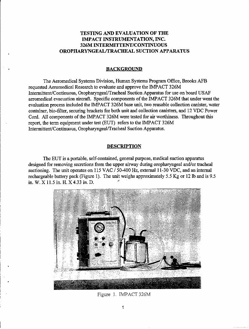
The EUT is a portable, self-contained, general purpose, medical suction apparatusdesigned for removing secretions from the upper airway during oropharyngeal and/or trachealsuctioning. The unit operates on 115 VAC / 50-400 Hz, external 11-30 VDC, and an internalrechargeable battery pack (Figure 1). The unit weighs approximately 5.5 Kg or 12 lb and is 9.5in. W. X 11.5 in. H. X 4.33 in. D.
Figure 1. IMPACT 326M
PROCEDURES
Test methods and performance criteria were derived from nationally recognizedperformance guidelines (1 & 5), various military standards (2-4 & 6-8), and manufacturer'sliterature (9). The Aeromedical Research Procedures Guide describes additional safety andhuman interface issues to be considered during equipment testing (10). A test setup andperformance check were developed specific to this EUT to verify its proper functioning of theequipment under various testing conditions. All tests are conducted by Aeromedical Researchpersonnel assigned to the Systems Research Branch (CFTS), Crew Technology Division,Armstrong Laboratory, Brooks AFB, TX., unless otherwise noted.
The EUT was subjected to various laboratory and inflight tests to observe and evaluate itsperformance under anticipated operational conditions.
1. Initial Inspection
2. Vibration
3. Electromagnetic Interference (EMI)
4. Thermal/ Humidity Environmental Conditions, encompassing:
a. Hot Operation
b. Cold Operation
c. Humidity Operation
d. Hot Temperature Storage
e. Cold Temperature Storage
5. Hypobaric Conditions
a. Cabin Pressure/Altitude
b. Rapid Decompression to Ambient Pressure
6. Airborne Performance
INITIAL INSPECTION AND TEST PREPARATION
a. The EUT was inspected for quality of workmanship, production techniques and pre-existing damage.
2
b. The EUT was checked to ensure it met safety requirements and operatingcharacteristics established in National Fire Protection Agency (NFPA) 99 (1), Electrical ShockHazards, AF 41-203 (2), and Equipment Management in Hospitals, AFI 41-201 (3). Groundresistance and leakage current measurements were made at 115 VAC/60 Hz and 115 VAC/400Hz.
c. The EUT was examined to ensure it met basic requirements for human factors designas outlined in MIL-STD 1472 (4).
d. A test setup and performance check were developed to evaluate the EUT's operation inaccordance with manufacturer/customer specifications throughout the various testing conditions.
TEST SETUP
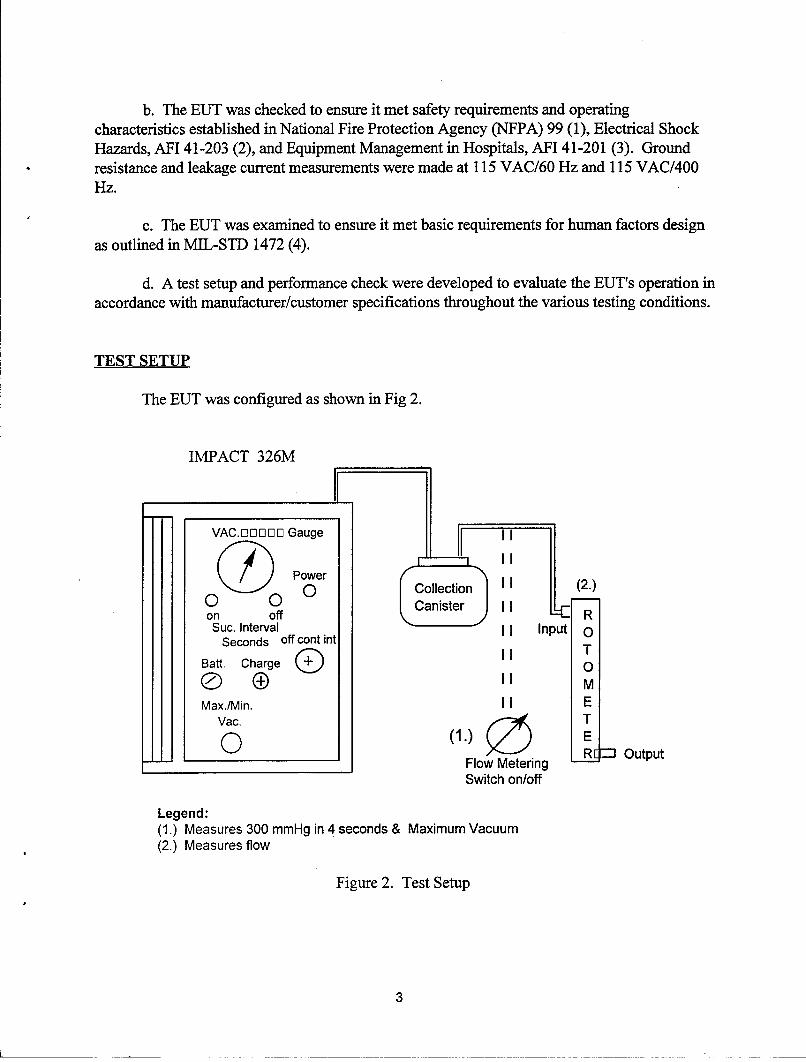
The EUT was configured as shown in Fig 2.
IMPACT 326M
III
0 0 Collection (2.)0 (0 Canister
on off RSuc. Interval I Input O
Seconds off cont int T
Batt. Charge M
Max./Min.II E
Vac. T(1.) E
Flow Metering R_" Output
Switch on/off
Legend:(1.) Measures 300 mmHg in 4 seconds & Maximum Vacuum(2.) Measures flow
Figure 2. Test Setup
3
PERFORMANCE CHECK
The following performance check was used to validate the function of the EUT duringeach of the following test conditions:
Time to Reach 300 mmHg suction as outlined in ECRI (5) - Attach collection tubing tothe collection canister, turn unit on, set vacuum adjust to "maximum", use a stopwatch to time anend point of 300 mmHg upon occlusion of collecting tube, repeat test 3 times, record results.Then connect a rotometer to the collection tubing to measure unit's free airflow, record results.Check unit in AC, 28 VDC and battery power modes.
Maximum Vacuum Level as outlined in ECRI (5) - Attach collection canister withcollection tubing to unit, select continuous mode, occlude collection tubing, set vacuum adjust tomaximum, turn unit on to ascertain maximum vacuum level, record results. Check unit in AC,28 VDC and battery power modes.
Battery Operation as outlined in IMPACT Instrumentation Inc., Operations & ServiceManual (9) - The battery pack can be recharged from the external 115 VAC source in 16 hours.
VIBRATION
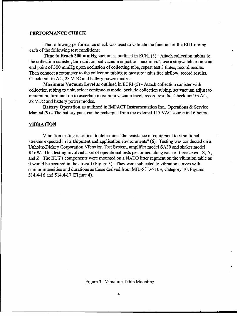
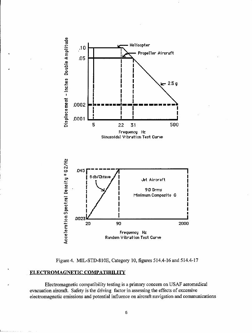
Vibration testing is critical to determine "the resistance of equipment to vibrationalstresses expected in its shipment and application environments" (6). Testing was conducted on aUnholtz-Dickey Corporation Vibration Test System, amplifier model SA30 and shaker modelR16W. This testing involved a set of operational tests performed along each of three axes - X, Y,and Z. The EUT's components were mounted on a NATO litter segment on the vibration table asit would be secured in the aircraft (Figure 3). They were subjected to vibration curves withsimilar intensities and durations as those derived from MIL-STD-81 E, Category 10, Figures514.4-16 and 514.4-17 (Figure 4).
Figure 3. Vibration Table Mounting
4
CD
_ .0 - •Helicopter
2 I Propeller Aircraft"=4: .05 "
, IC.) I Io I I"-" I I4- II
,- L 2.5 g
oI I I
E .0002 MIM MMMOMMI ----
-•I I I,I I I
"a .0001 I I-2n 5 22 31 500
Frequency HzSinusoidal Vibration Test Curve
'-' .0001
I dbt4tF a Jet Aircraft
Minimum Composite 0
D0 •23• SII
20 90 2000) Frequency Hz
Random Vibration Test Curve
Figure 4. MIL-STD-8lOBE, Category 10, figures 514.4-16 and 514.4-17
ELECTROMAGNETIC COMPATIBILITY
Electromagnetic compatibility testing is a primary concern on USAF aeromedicalevacuation aircraft. Safety is the driving factor in assessing the effects of excessiveelectromagnetic emissions and potential influence on aircraft navigation and communications
5
equipment. Medical devices may be susceptible to fields generated by aircraft equipment, andmalfunction in their presence.
The EUT was evaluated for compliance with MIL-STD-461D & MIL-STD-462D (7 & 8).ASC/ENAI engineers at Wright-Patterson AFB evaluated the electromagnetic compatibility, dataand determined the airworthiness of the medical device. Specific tests conducted were asfollows:
a. Radiated Emissions (RE-102), "Radiated Emissions, Electric Field, 10kHz to 18 GHz.": For Air Force aircraft applications, radiated emissions were tested in anarrower range of frequencies from 2 MHz - 1 GHz. This test measured the amount of EMIemitted by the EUT during operation. It verifies the EUT's potential to affect other equipmentsusceptible to electromagnetic emissions (i.e., aircraft navigation and communicationsequipment).
b. Conducted Emissions (CE-102), "Conducted Emissions, Power Leads,10 kHz to 10 MHz.": For Air Force aircraft applications, conducted emissions were testedthroughout the entire band of 10 kHz - 10 MHz. This test measured emissions generated by theEUT along its power supply lines. It was performed to assess the EUT's potential to affect otheritems connected to the same power source, particularly aircraft systems.
c. Radiated Susceptibility (RS-103), "Radiated Susceptibility, ElectricField, 10 kHz to 40 GHz.": For Air Force aircraft applications, radiated susceptibility was testedin a narrower frequency range from 30 MHz - 12.4 GHz at the following field strength levels: 20V/M below 1 GHz and 60 V/M above 1 GHz (MIL-STD-461D field strength values from TableIV, Category Aircraft Internal). This test evluated the EUT's resistance to predefined levels ofEMI generated by antennas both internal and external to the aircraft.
d. Conducted Susceptibility (CS- 101), "Conducted Susceptibility, PowerLeads, 30 Hz to 50 kHz.": For Air Force aeromedical aircraft applications, conductedsusceptibility was tested throughout the entire frequency band, from 30 Hz to 50 kHz. This testevaluated the EUT's ability to "withstand ripple voltages associated with allowable distortion ofpower source voltage wave forms."
e. Conducted Susceptibility (CS-1 14), "Conducted Susceptibility, BulkCable Injection, 10 kHz to 400 MHz.": For Air Force aeromedical aircraft applicationsconducted susceptibility was tested throughout the frequency band from 10 kHz to 200 MHz.This test determined whether "simulated currents that will be developed on platform cablingfrom electromagnetic fields generated by antenna transmission would affect the equipment undertest."
f. Conducted Susceptibility (CS-1 15), "Conducted Susceptibility, BulkCable Injection, Impulse Excitation": This test was performed to ensure the EUT couldwithstand the "fast rise and fall time that may be present due to platform switching operationsand external transient environments such as lightning and electromagnetic pulse."
6
g. Conducted Susceptibility (CS-1 16), "Conducted Susceptibility,Damped Sinusoidal Transients, Cables and Power Leads, 10 kHz - 100 MHz," respectively. The"basic concept of this test is to simulate electical current and volatge waveforms occurring inplatforms from excitation of natural resonances."
During emissions testing, all EUT's electrical components were operating for the durationof the test to create the worst case emissions scenario. In these tests, the EUT operated in themaximum vacuum mode. For susceptibility testing, the EUT was operated again in themaximum vacuum mode. For both emissions and susceptibility testing, the EUT was tested foroperation on 115 VAC/60, 400 Hz, and internal batteries.
THERMAL/HUMIDITY ENVIRONMENTAL CONDITIONS
Extreme temperature and humidity testing determines if aeromedical equipment can bestored and operated during severe environmental conditions "without experiencing physicaldamage or deterioration in performance." (6) Extreme environmental conditions can haveincapacitating effects on medical equipment including the following: changes in materialcharacteristics and material dimensions, overheating, changes in lubricant viscosity, changes inelectronic components, and electronic or mechanical failures due to rapid water or frostformation.
Testing was conducted in the Armstrong Laboratory's Thermotron Industries, modelSM-32 environmental chamber. The EUT was placed in the center of the environmentalchamber. All input and output cables and wires were routed through a port in the chamber wall,which was subsequently sealed with a precut sponge plug. The other components of the testsetup remained outside the chamber. For operational tests, the EUT was monitoredcontinuously, and a performance check was conducted every 15 minutes. For storage tests, theEUT was placed in the chamber and remained nonoperational throughout the storage portion ofthe test. The following describes the conditions of the environmental tests performed:
a. Humidity Operation: 94 ± 4% RH, 85°F ± 3.6'F (29.5'C ± 2°C) for 4 hr
b. Hot Temp Operation: 120'F -3.6OF (49oC ± 2oC) for 2 hr
c. Cold Temp Operation: 32°F ± 7.2°F (0°C ± 4°C) for 2 hr
d. Hot Temp Storage: 140'F ± 3.6°F (60'C ± 2°C) for 6 hr
e. Cold Temp Storage: -40'F ± 3.6°F (-40'C ± 2°C) for 6 hr
7
HYPOBARIC CONDITIONS
Cabin Pressure/Altitude: Altitude testing is critical for aeromedical evacuationequipment due to potential effects of barometric pressure changes on the equipment. A majorityof the aircraft characterized as opportune aircraft available for use in aeromedical evacuation,pressurize their cabin atmosphere to barometric pressures equivalent to 8,000-10,000 ft above sealevel. The differences in pressures affect the operation of some medical equipment. Altitudetesting consisted of operating the EUT while ascending from ground level to 10,000 ft; stoppingat 2,000 ft increments for performance checks; and then descending back to ground, at rates of5,000 ft/min. Descent is stopped at 2,000 ft for performance checks.
Decompression Testing: A decompression is the loss of aircraft cabin pressurization andsubsequent pressure equalization with ambient atmospheric pressures. It is important to assessmedical equipment functioning during and after decompression so as not endanger a patient,personnel, or the aircraft itself. The EUT operated inside the decompression test chamber as thechamber was pressurized to an equivalent of 8,000 ft altitude. Then, the chamber altitude wasbrought to 45,000 ft over a period of 60 seconds, held at 45,000 ft for a few minutes, and thenreturned to ground at a rate of 10,000-12,000 ft/min. The test was repeated twice more; once fora 7-second decompression and once for a 1-second decompression. The EUT was monitoredthroughout the series of decompressions; performance checks were assessed each time the unitreturned to ground level.
AIRBORNE PERFORMANCE
Airborne performance evaluations are a cost-effective and invaluable means ofvalidating clinical and operational suitability under actual operating conditions. By carefullyevaluating medical equipment items in their proposed operational environment, AeromedicalResearch verifies demonstration of all pertinent patient care issues are adequately addressed bythe test protocols. Safe and reliable operation is the primary goal of the inflight evaluation andforms the basis for subsequent recommendations to the users.
This phase of testing was conducted by qualified aeromedical crew members fromAeromedical Research on a C-9 aeromedical evacuation mission. The EUT was positioned andsecured to the aircraft stantion pole and evaluated. Human factors characteristics, securingmethods, setup/tear down times and securing locations were also evaluated. Feedback from otheraeromedical evacuation crew members participating in delivery of patient care was obtainedconcerning EUT human factor considerations.
8
EVALUATION RESULTS
INITIAL INSPECTION
Initial inspection revealed two problems, first, a power distribution problem located in themain power supply. The problem was a mis-wiring of the main transformer. Second, the powercord connection into the unit would not allow disconnection and reconnection during normalroutine use. The manufacturer replaced the power cable and implemented a securing method tomaintain the connection during aircraft vibrations. Once the manufacturer corrected thesedefects the unit performed to the manufacturer's specification. Electrical safety test resultsshowed all parameters to be within referenced guideline limits. Battery Endurance revealed a 2hour operation time well within manufacturer's specifications.
VIBRATION
The gauge on the EUT became unstable and experienced violent oscillations when thevacuum output was set to maximum (in all three axis). The output flow of EUT was reduced to20 inHg and the oscillations dampened significantly. This was the only deviation from thevibration testing protocol. The unit then performed according to manufacturers specifications.
ELECTROMAGNETIC COMPATIBILITY
ASC/ENAI, Wright-Patterson AFB certified the EUT for use in aeromedical evacuationsystem on all U.S. Air Force aircraft while operating from 115 VAC/60-400 Hz, 28VDC &battery power.
THERMAL/HUMIDITY ENVIRONMENTAL CONDITIONS
The EUT operated satisfactorily during all five phases of testing. Testing was conductedin the Armstrong Laboratory's Thermotron Industries, model SM-32 environmental chamber.
HYPOBARIC CONDITIONS
1. Cabin Pressure/Altitude: The EUT performed in accordance with manufacturer'sspecifications throughout testing. The unit was able to deliver 29 1pm flow at 10,000 ft cabinaltitude. Reading on EUT gauge was approximately 16 inHg.
2. Rapid Decompression: The EUT operated satisfactorily following each decompression.
9
AIRBORNE PERFORMANCE
The inflight evaluation of the EUT was performed on a C-9 aeromedical evacuationmission. Evaluation confirmed that the unit would operate successfully during all phases offlight. Analysis of flight data indicated this unit was easy to enplane and deplane and wascompatible with aircraft electrical systems. It was noted the power cord length is not sufficientwhen securing the unit to the stantion pole of the C-9 aircraft.
SUMMARY
Aeromedical Research found the IMPACT Instruments, Inc. IMPACT 326M tobe acceptable for use on all U.S. Air Force aeromedical evacuation aircraft while operating on115 VAC/60 - 400Hz, 28 VDC or battery power with the recommendations listed below. TheEUT operated within expected parameters when subjected to environmental extremes andsimulated cabin altitudes, and did not produce a hazard during rapid decompression. Thefollowing recommendations apply:
a. The Specification Sheet, Page 6-1, from the 326M Instruction Manual still reads thatthe unit can only run for 27 minutes/hour when using 117 VAC External Power. TheSpecification Sheet should be changed to reflect current model.
b. Power cord should be at least eight feet long in order to reach power receptacles on theC-9A aircraft when the unit is secured to the aircraft floor.
c. Velcro securing straps on the soft-sided transport case should be lengthened to allowsecuring the unit to the litter equipment brackets.
d. Change the value of Capacitor #C20 (manufacturer's schematic) from 1000 gtfd to10,000 4fd.
e. Add the following components to allow battery meter to read battery charge conditionswhen operating in continuous suction mode. Regulator #U13, capacitors #C33 and #C34(manufacturer's schematic.)
f. Add an External power lamp #LP2 (manufacturer's schematic) to provide visualfeedback when connected to live Alternating Current (AC) mains.
g. Change the external power jack from a connector with a conductive shell and screw-type locking mechanism to P.N.: 708-0750-01 with an aluminum threaded sleeve to secure theAC power supply output plug to the external power jack.
h. Move the bridge rectifier #BRi (manufacturer's schematic) from main suction unit toAC power supply.
10
i. Replace the metal serial number label and replace with a pressure sensitive serialnumber label. This metal label is used as a heat sink for the bridge rectifier (BRI- manufacturer'sschematic).
j. Connect the transformer dual primary windings in parallel for 115 VAC operation.
k. Resize velcro retaining straps that secure battery pack to improve ease by which usercan grab, and separate, the battery pack retaining straps.
1. Round edges to the stainless steel collection canister attachment brackets to eliminatesharp, 9.00 comers.
m. Eliminate protrusions of screws into battery compartment by providing a centerchannel to stainless steel collection canister attachment brackets.
*NOTE: The EUT was subjected to multiple endurance runs to evaluate the affects of long term
use. Tests included: 16 hour continuous free flow and intermittent operation utilizing 115VAC/60 Hz power and 16 hour continuous free flow utilizing 115 VAC/400 Hz power. The unitfunctioned in accordance with manufacturer specifications throughout this phase of testing. Nodegradation in the unit's operability was observed during these tests.
"**NOTE: Aeromedical Research identified one additional area for possible improvement. A
method to secure the power supply to the base unit will prevent the weight of the power supplyfrom inducing excessive stress and strain on the unit's input power receptacle while alsoenhancing ease of transporting the power supply and unit.
11
REFERENCES
1. National Fire Protection Agency (NFPA) 99, Health Care Facilities Code
2. AFI 41-203, Electrical Shock Hazards
3. AFI 41-201, Equipment Management in Hospitals
4. MIL-STD 1472, Human Engineering Design Criteria for Military Systems, Equipment, andFacilities.
5. Emergency Care Research Institute (ECRI)
6. MIL-STD 810E, Environmental Test Methods and Engineering Guidelines.
7. MIL-STD 461D, Electromagnetic Emission and Susceptibility Requirements for the Controlof Electromagnetic Interference.
8. MIL-STD-462 D, Measurement of EMI Characteristics.
9. IMPACT Instrumentation Inc., IMPACT 326M, Operations & Service Manual.
10. Aeromedical Research Procedures Guide, Internal Operating Instruction, Systems ResearchBranch, Armstrong Laboratory.
12
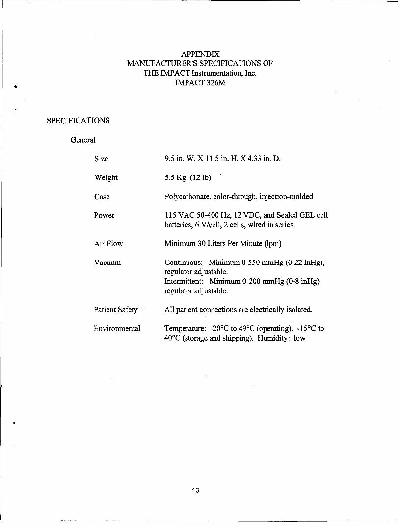
APPENDIXMANUFACTURER'S SPECIFICATIONS OF
THE IMPACT Instrumentation, Inc.IMPACT 326M
SPECIFICATIONS
General
Size 9.5 in. W. X 11.5 in. H. X 4.33 in. D.
Weight 5.5 Kg. (12 ib)
Case Polycarbonate, color-through, injection-molded
Power 115 VAC 50-400 Hz, 12 VDC, and Sealed GEL cellbatteries; 6 V/cell, 2 cells, wired in series.
Air Flow Minimum 30 Liters Per Minute (1pm)
Vacuum Continuous: Minimum 0-550 mmHg (0-22 inHg),regulator adjustable.Intermittent: Minimum 0-200 nmmHg (0-8 inug)regulator adjustable.
Patient Safety All patient connections are electrically isolated.
Environmental Temperature: -20'C to 49'C (operating). -1 5'C to40'C (storage and shipping). Humidity: low
13