1998 WHIRLPOOL POWER CLEAN FILTER DISHWASHERS
36
CONSUMER SERVICES TECHNICAL EDUCATION GROUP PRESENTS KD-11 JOB AID Part No. 4322451L 1998 WHIRLPOOL POWER CLEAN FILTER DISHWASHERS
Transcript of 1998 WHIRLPOOL POWER CLEAN FILTER DISHWASHERS

I
CONSUMER SERVICES TECHNICALEDUCATION GROUP PRESENTS KD-11
JOB AIDPart No. 4322451L
1998 WHIRLPOOLPOWER CLEAN
FILTERDISHWASHERS

II
WHIRLPOOL CORPORATION ASSUMES NO RESPONSIBILITYFOR ANY REPAIRS MADE ON OUR PRODUCTS BY ANYONE
OTHER THAN AUTHORIZED SERVICE TECHNICIANS.
© 1998 Whirlpool Corporation, Benton Harbor, MI 49022
CORPORATION
INTRODUCTIONThis Job Aid, “1998 WHIRLPOOL POWER CLEAN FILTER DISHWASHERS,” (Part No. 4322451)provides specific information for the installation, service and repair of 1998 Whirlpool Dishwashersequipped with Power Clean Filter pump and motor modules.
“1998 WHIRLPOOL POWER CLEAN FILTER DISHWASHERS,” has been compiled to provide themost recent information on design, features, troubleshooting, service and repair procedures.
GOALS AND OBJECTIVESThe goal of this Job Aid is to provide detailed information that will enable the service technician toproperly diagnose malfunctions and repair the 1998 lineup of Dishwashers.
The objectives of the Job Aid are:
The service technician will -
• Understand proper safety precautions.• Successfully troubleshoot and diagnose malfunction.• Successfully perform necessary repairs.• Successfully return the dishwasher to proper operational status.
ADDITIONAL INFORMATIONComplete instructions on the disassembly and servicing of the Power Clean Filter Module are avail-able in the Job Aid, “POWER CLEAN FILTER PUMP MOTOR ASSEMBLY SERVICE,” Part No.4322455. This Job Aid, and the accompanying video tape, Part No. 4322456V, have been revised toinclude specific details on the most recent version of this dishwasher pump and motor assembly.
III
TABLE OF CONTENTSINTRODUCTION. . . . . . . . . . . . . . . . . . . . . . . . . . . . . . . . . . . . . . II
TABLE OF CONTENTS. . . . . . . . . . . . . . . . . . . . . . . . . . . . . . . . . III
SECTION ONETHEORY OF OPERATIONConsole Configuration . . . . . . . . . . . . . . . . . . . . . . . . . . . . . . . . . . . . . . . . 1Pump and Motor Operation . . . . . . . . . . . . . . . . . . . . . . . . . . . . . . . . . . . . 2
SECTION TWOCOMPONENT ACCESSComponent Location . . . . . . . . . . . . . . . . . . . . . . . . . . . . . . . . . . . . . . . . 3Removing Access and Outer Door Panels . . . . . . . . . . . . . . . . . . . . . . . . . 4Removing the Heater Element . . . . . . . . . . . . . . . . . . . . . . . . . . . . . . . . . . 5Replacing the Heater Element . . . . . . . . . . . . . . . . . . . . . . . . . . . . . . . . . . 5Servicing the Vertical Water Tube . . . . . . . . . . . . . . . . . . . . . . . . . . . . . . . 6Removing the Pump and Motor Assembly . . . . . . . . . . . . . . . . . . . . . . . . 7Servicing the Operating Thermostat . . . . . . . . . . . . . . . . . . . . . . . . . . . . . 8Servicing the Soil Sensing System . . . . . . . . . . . . . . . . . . . . . . . . . . . . . . 8Removing the Inside Door Panel . . . . . . . . . . . . . . . . . . . . . . . . . . . . . . . . 8Dishwasher Dispenser Disassembly . . . . . . . . . . . . . . . . . . . . . . . . . . . . . 9
SECTION THREEDIAGNOSIS AND TROUBLESHOOTINGTroubleshooting Guide (Model DU910PFG) . . . . . . . . . . . . . . . . . . . . . . . 11Troubleshooting Guide (Models DP920PFG, DU920PFGGU940SCG, GU960SCG, GU980SCG) . . . . . . . . . . . . . . . . . . . . . . . . . . . 12Component Diagnosis . . . . . . . . . . . . . . . . . . . . . . . . . . . . . . . . . . . . . . . . 13
SECTION FOURTECH TIPSWiring Diagram and Cycle Timing Chart (Model DU910PFG). . . . . . . . . . 15Strip Circuits (Model DU910PFG) . . . . . . . . . . . . . . . . . . . . . . . . . . . . . . 16Wiring Diagram (Model DP920PFG, DU920PFG, GU940SCG,GU960SCG, GU980SCG) . . . . . . . . . . . . . . . . . . . . . . . . . . . . .. . . . . . . . . 18Cycle Timing Chart (Model DP920PFG, DU920PFG,GU940SCG, GU960SCG, GU980SCG) . . . . . . . . . . . . . . . . . . . . . . . . . . . 19Cycle Timing Chart Notes (Model DP920PFG, DU920PFG,GU940SCG, GU960SCG, GU980SCG) . . . . . . . . . . . . . . . . . . . . . . . . . . . 20Diagnostic and Sales Demo Timing Chart (Model DP920PFG,DU920PFG, GU940SCG, GU960SCG, GU980SCG) . . . . . . . . . . . . . . . . 21Strip Circuits (Model DP920PFG, DU920PFG, GU940SCG,GU960SCG, GU980SCG) . . . . . . . . . . . . . . . . . . . . . . . . . . . . . . . . . . . . . 22Custom Door Panel Conversion . . . . . . . . . . . . . . . . . . . . . . . . . . . . . . . . . 23Floor Mount Kit . . . . . . . . . . . . . . . . . . . . . . . . . . . . . . . . . . . . . . . . . . . . 27Warranty Information . . . . . . . . . . . . . . . . . . . . . . . . . . . . . . . . . . . . . . . . 28Model and Serial Number Designators . . . . . . . . . . . . . . . . . . . . . . . . . . 29Service Contact Information . . . . . . . . . . . . . . . . . . . . . . . . . . . . . . . . . . 30

IV

1
Section OneTHEORY OF OPERATION
1998 POWER CLEAN FILTER MODELSConsole ConfigurationModel DU910PFG
Models DP920PFG, DU920PFG
Model GU940SCG
Model GU960SCG
Model GU980SCG
2
1. Once the tub has filled with hot water the motor begins to rotate forcing the water up through thepump chamber and out through the spray arms. Two spray jets on the underside of the lowerspray arm direct water down onto the fine mesh screen of the pump housing to clear soils thatmay collect there during the wash cycle.
2. As water and soils return to the lower pump area, the chopper blade grinds the particles intosmaller sizes that then pass through the perforated plate into the upper chamber of the pump.The pump impeller causes the soil ladened water to be lifted and moved to the outer edges ofthe pump chamber where they are forced into the separator. Clean water is then forced upthrough the spray arms and fine mesh screen.
3. When the drain cycle begins, the drive motor changes direction. This relieves the pressure onthe two check balls, opening the drain system.
4. Water is pumped from the tub carrying soils from the separator into the drain sump of the pump.
5. Soiled water is pumped out of the dishwasher through the check valve and drain hose.
PUMP AND MOTOR OPERATION

3
COMPONENT LOCATION
TIMER
LATCHASSEMBLY
FILLVALVE
MOTORRELAY
FLOATSWITCH
OPERATINGTHERMOSTAT
(Attached to bottomof pump housing)
HI LIMITTHERMOSTAT
PUMP ANDMOTOR
ASSEMBLY
HEATER
DETERGENTAND RINSE AID
DISPENSERASSEMBLY
PROGRAMSWITCHES
INDICATORLIGHTS
Section TwoCOMPONENT ACCESS

4
Removing Access and Outer Door Panels
1. Loosen but do not remove the two (2) toe panel screws below the access panel. Remove andset aside the two (2) screws above the access panel. (Fig. 2-1)
2. Remove the access panel assembly by sliding it upward to clear the loosened screws. (Fig. 2-1)
3. Remove the two (2) screws from the bottom of the outer door panel. (Fig. 2-1)
4. Pull the bottom of the outer door panel outward and slide it down approximately ¼” to ½”. Thepanel will then be free for removal. (Fig. 2-1, inset)
5. Remove the existing door insulation. Access to the detergent and rinse aid dispensers is nowpossible.
Fig. 2-1

5
Removing the Heater Element
From beneath the cabinet:
1. Remove the front access panel. (See Removing the Outer Door Panel)
2. Pull the spade connectors off the heater element terminals.
3. Unscrew the two (2) nuts securing the heater element to the bottom of the tub. (Fig. 2-2)
From inside the tub:
4. Remove the lower dish rack.
5. Remove the lower spray arm.
6. Slide the metal disks from the metal clips securing the left and right sides of the heater element.
7. Carefully lift the heater element from the unit.
Replacing the Heater Element
From inside the tub:
1. Carefully place the terminal ends of the heater element through the two (2) holes at thebottom rear of the cabinet.
2. Slide the metal disks into the clips to secure the left and right sides of the heater element.
3. Replace the lower spray arm.
4. Replace the lower dish rack.
From underneath the cabinet:
5. Secure the heater element in place with two (2) nuts. Be sure the element is seated firmlyagainst the tub.
6. Slide the spade connectors onto the heater element terminals.
7. Replace the front access panel.
Fig. 2-2
Element Retaining Nuts (2)
6
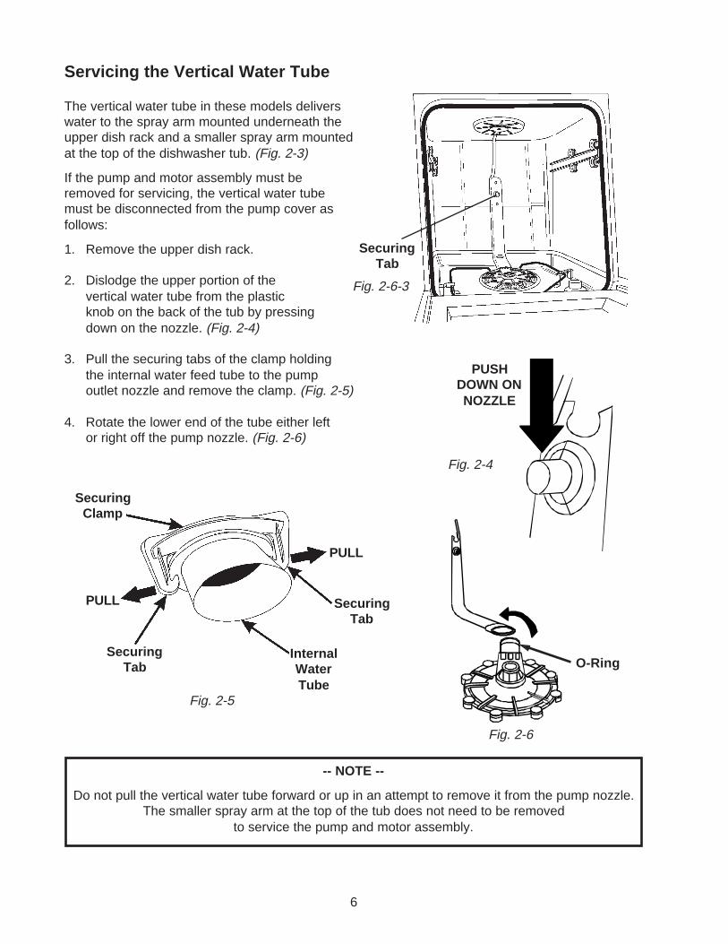
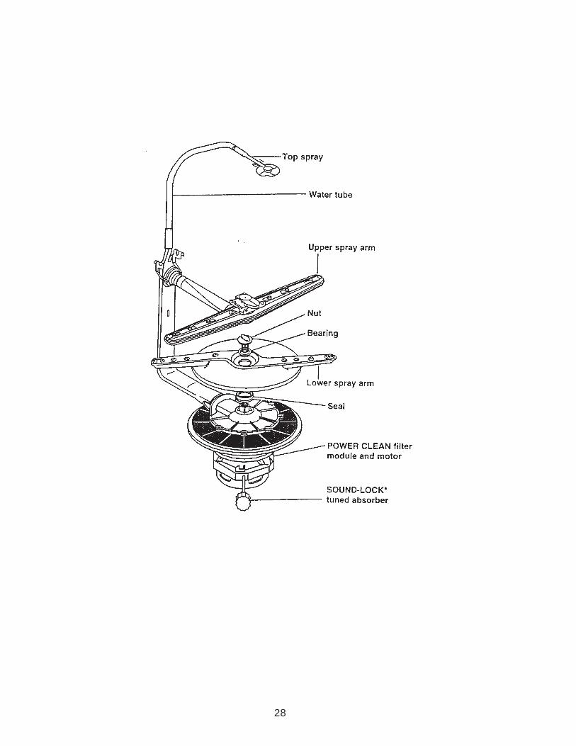
Servicing the Vertical Water Tube
The vertical water tube in these models deliverswater to the spray arm mounted underneath theupper dish rack and a smaller spray arm mountedat the top of the dishwasher tub. (Fig. 2-3)
If the pump and motor assembly must beremoved for servicing, the vertical water tubemust be disconnected from the pump cover asfollows:
1. Remove the upper dish rack.
2. Dislodge the upper portion of thevertical water tube from the plasticknob on the back of the tub by pressingdown on the nozzle. (Fig. 2-4)
3. Pull the securing tabs of the clamp holdingthe internal water feed tube to the pumpoutlet nozzle and remove the clamp. (Fig. 2-5)
4. Rotate the lower end of the tube either leftor right off the pump nozzle. (Fig. 2-6)
Fig. 2-6-3
SecuringTab
Fig. 2-4
Fig. 2-6
Fig. 2-5
SecuringTab
SecuringTab
InternalWaterTube
SecuringClamp
PULL
PULL
PUSHDOWN ONNOZZLE
-- NOTE --
Do not pull the vertical water tube forward or up in an attempt to remove it from the pump nozzle.The smaller spray arm at the top of the tub does not need to be removed
to service the pump and motor assembly.
O-Ring

7
Removing the Pump Motor Assembly
1. Unscrew and remove the nozzle cap and removethe nozzle bearing and spray arm. (Fig. 2-7)
2. Disconnect the wiring harness from the motorharness plug.
3. Rubber clamps secure the pump and motorassembly to the tub. Rotate these inward 90°.(Fig. 2-8)
4. Remove the drain hose and clamp from thecheck valve and unscrew the check valve from the pump. (Fig. 2-9)
5. Remove the tuned sound absorber. Use an open-end wrench to loosen the shaft from themotor. Do not loosen the sound absorber by torquing on the large tuned resonator.
-- NOTE --
A small container will be required to catch water from the drain hose after removal.
Fig. 2-7SPRAY ARM
NOZZLECAP
NOZZLE BEARING
6. Remove the pump and motor assembly by pulling up through the inside of the tub. (Fig. 2-10)
Fig. 2-10
Fig. 2-8
ClampShown Rotated
Inward 90°
Check Valve
Drain HoseClamp
DrainHose
Fig. 2-9
TunedSound
Absorber

8
Servicing the Soil Sensing System
The Soil Sensing System consists of a pressure sensitive switch connected to the dishwasher pumpbase. (Fig. 2-12) The system detects excessive amounts of food soils during the sensing portion of thewash cycle and signals the electronic control board to either terminate the wash cycle and initiatedrain to flush soils from the system or skip certain parts of the heavy soil cycle.
The pressure switch is connected to the pump base through a plastic hose. The pressure switch issecured to the bottom of the dishwasher tub by two (2) Hex- head screws.
Pressure Switch
Plastic Tube
Fig. 2-12
Servicing the Operating Thermostat
The operating thermostat is secured to the bottomof the pump housing. (Fig. 2-11)
1. Disconnect the two (2) wiring harness leadsfrom the terminals on the thermostat.
2. Remove the two (2) Hex-head screwssecuring the thermostat to the pump housing.
Fig. 2-11Operating
Thermostat
1. Disconnect the dishwasher from the electrical supply.
2. Disconnect the end of the door springsfrom the door spring tension adjustmentholes in the frame runner.
3. Open the dishwasher door and remove theeight (8) T-15 Torx screws securing the innerdoor panel from the door frame. (Fig. 2-13)
4. Slide the inner door panel back toward the dish-washer to disengage the spring loaded lockingtab from the door panel, then lift the door panelaway from the door. (Fig. 2-14)
4. Remove the control cover.
Removing the Inside Door Panel
Fig. 2-14
T-15TORX
Fig. 2-13
Spring LoadedLocking Tab
Inner DoorPanel
SLIDE INNER DOORPANEL TOWARD
DISHWASHER

9
Fig. 2-15
Fig. 2-16
Dishwasher DispenserDisassembly
1. Remove the drawbar spring. (Fig. 2-15)
2. Grasp the lower edge of the drawbarand pull it away from the panel stop.Slide the drawbar down until the drawbar holes align with the locking tabs,then remove the drawbar. Note how thelocating tabs behind the drawbar alignwith their respec-tive locating holes inthe drawbar. (Fig. 2-16)
3. Turn the wet agent cap and seal assem-bly counterclockwise and remove it.(Fig. 2-17)
4. Remove the seal from the cap.
5. Use Special Tool - Part No. 303918 or a¾” socket to press over the attachingtabs in the wet agent cap opening.Remove wet agent dispenser assembly.(Fig. 2-17)
6. Remove wet agent dispenser actuatorby spreading the two (2) locking tabs.(Fig. 2-18)
7. Remove the actuator slide from the wetagent dispenser actuator.
8. Remove the diaphragm spring anddiaphragm.
9. Use a screwdriver to gently release thelower tab and remove the detergentdoor actuator assembly. As you do,note the position of the door latch levelthrough the hole in the lower slide.(Fig. 2-19)
10. Remove the detergent door latch bycarefully spreading the latch snaplocking tabs apart with a screwdriverwhile pushing firmly against the end ofthe door latch lever until the lever isreleased through the hole.
11. Remove the upper slide, the slidespring and the lower slide. (Fig. 2-20)

10
Fig. 2-17Fig. 2-18
Fig. 2-19
Fig. 2-20

11
TROUBLESHOOTING GUIDEModel DU910PFG
PRECAUTIONS TO BE OBSERVED WHILETROUBLESHOOTING
Always check wiring harness and connectors before initiating any test procedures.
Disconnect electric power from the dishwasher before touching the printed circuit boards or re-seating wire connectors.
Voltage checks should be made by inserting meter probes beside the wires in the connector blocks with the electric power source onand the connector block plugged in.
Resistance checks should be made on components with the electric power off and the connector blocks disconnected.
PROBLEM POSSIBLE CAUSES CORRECTION/TESTDishwasher does not run orstops during a cycle
Dishwasher will not fill
Dishwasher will not drain
Dishwasher will notdry dishes
1. Door is not latching properly.
2. Child lock is "ON".3. Wash Cycle not set properly.
4. Household fuse blown or circuitbreaker tripped.
5. Washer is not wired into a circuit withproper voltage.
1. Overflow protection float is stuck in"up" position.
2. Fill valve is inoperable.
3. Open timer contacts.
1. Air gap (if installed) is clogged.
2. Pump motor is inoperable.
3. Open timer contacts.
1. Heater element burned out.
2. HI-limit thermostat inoperable.
3. Open circuit between timer andheater.
1. Check to make sure handle linkis properly seated in door latchassembly. Check that the doorswitch is opening and closingproperly.
2. Turn child lock "OFF"3. Review setting Wash Cycles in
the Use and Care Guide.4. Have a qualified electrician check
the circuit breaker or fuse.5. Have customer call a qualified
electrician.
1. Check that the overflowprotection float is free to move"up" and "down". Check that theoverfill switch in opening andclosing properly.
2. Check for continuity betweencontacts on fill valve.
3. Test timer contacts.
1. Follow air gap manufacturer'sdirection for cleaning.
2. Disconnect pump motor fromwiring harness and check forcontinuity.
3. Test timer contacts.
1. Check for continuity between theterminals of the heater element.
2. Check for continuity betweenterminals of the hi-limitthermostat.
3. Check for continuity betweentimer switch contacts and heater.
Section ThreeDIAGNOSIS AND TROUBLESHOOTING

12
PROBLEM POSSIBLE CAUSES CORRECTION/TESTDishwasher does not run orstops during a cycle
Dishwasher will not fill
Dishwasher will not drain
Dishwasher will notdry dishes
1. Door is not latching properly.
2. Child lock is "ON".3. Wash Cycle not set properly.
4. Household fuse blown or circuitbreaker tripped.
5. Washer is not wired into a circuit withproper voltage.
1. Overflow protection float is stuck in"up" position.
2. Fill valve is inoperable.
3. Control board is inoperable.
1. Air gap (if installed) is clogged.
2. Pump motor is inoperable
3. Control board is inoperable.
1. Heater element burned out.
2. Hi-limit thermostat inoperable.
1. Check to make sure handle linkis properly seated in door latchassembly. Check that the doorswitch is opening and closingproperly.
2. Turn child lock "OFF"3. Review setting Wash Cycles in
the Use and Care Guide.4. Have a qualified electrician check
the circuit breaker or fuse.5. Have customer call a qualified
electrician.
1. Check that the overflowprotection float is free to move"up" and "down". Check that theoverfill switch in opening andclosing properly.
2. Check for continuity betweencontacts on fill valve.
3. Check for 110VAC between P2-5and P12-3.
1. Follow air gap manufacturer'sdirection for cleaning.
2. Disconnect pump motor fromwiring harness and check forcontinuity between V & BU, V &GY and V & Y.
3. Check for 110VAC between P10and P3, P10 and P5 and P10and P4.
1. Check for continuity between theterminals of the heater element.Check for 110VAC between P6and P8.
2. Check for continuity betweenterminals of the hi-limitthermostat.
PRECAUTIONS TO BE OBSERVED WHILETROUBLESHOOTING
Always check wiring harness and connectors before initiating any test procedures.
Disconnect electric power from the dishwasher before touching the printed circuit boards or re-seating wire connectors.
Voltage checks should be made by inserting meter probes beside the wires in the connector blocks with the electric power sourceon and the connector block plugged in.
Resistance checks should be made on components with the electric power off and the connector blocks disconnected.
TROUBLESHOOTING GUIDEModels DP920PFG, DU920PFG, GU940SCG, GU960SCG and
GU980SCG

13
COMPONENT TESTING
PRECAUTIONS TO BE OBSERVED WHILE DIAGNOSINGPROBLEM COMPONENTS
Disconnect electric power from the dishwasher.
Voltage checks should be made by inserting meter probes beside the wires in the connector blocks with the electric power source onand the connector block plugged in.
Resistance checks should be made on components with the electric power off and the connector blocks disconnected.
COMPONENT SCHEMATIC TESTING PROCEDURE RESULTS
Motor Start Relay
Drive Motor
Thermal Fuse
Heater Element
Fill Valve
Overfill Switch
1. Disconnect the wire connectors andremove relay from unit.
2. Set VOM meter on the Rx1 scale.3. Set the relay upright.4. Measure resistance between blue
and violet contacts.5. Turn relay upside-down.6. Measure resistance between blue
and violet contacts.
1. Disconnect the motor wiring harnessplug from the motor connector.
2. Set VOM meter on the Rx1 scale.3. Connect one probe to the white/violet
connector.4. Connect the other probe to the blue/
white connector.5. Connect the meter probe to the yellow
connector.6. Connect the probe to the grey
connector.
1. Disconnect wires connectors from thethermal fuse terminals.
2. Set VOM meter to read Rx1 scale.3. Measure resistance between thermal
fuse terminals.
1. Disconnect the wire connectors fromthe heater element terminals.
2. Set VOM meter to read Rx1 scale.3. Measure resistance between heater
element terminals.
1. Disconnect the wiring harness plugfrom the fill valve connector.
2. Set VOM meter to read Rx1 scale.3. Measure resistance between the
terminals of the fill valve.
1. Disconnect the wires connectors fromthe overfill switch terminals.
2. Set VOM meter to read Rx1 scale.3. Measure resistance between switch
terminals.4. Block the float in the UP (full) position
and measure resistance again.
1. Relay upright - meter should readº (infinity.)
2. Relay upside-down - meter shouldread less than two (2)Ω.
1. Violet to blue - meter should read2.0 - 3.4Ω.
2. Violet to Yellow - meter shouldread 4.2 - 7.0Ω.
3. Violet to Gray - meter shouldread 4.2 - 7.0Ω.
1. Meter should read 0Ω.
1. Meter should read 25 - 35Ω.
1. Meter should read approximately700Ω.
1. Float DOWN - meter should read0Ω.
2. Float UP - meter should readº (infinity).

14
COMPONENT SCHEMATIC TESTING PROCEDURE RESULTSTimer Motor
Timer
Dispenser Mechanism
1. Disconnect the Wiring harnessconnector from the timer assembly.
2. Set VOM meter on the Rx1 scale.3. Measure resistance between timer
motor terminals.
1. Disconnect the wiring harnessconnector from the timer assembly.
2. Set VOM meter on the Rx1 scale.3. Connect one probe to contact 31.
(Tan)4. Connect the other probe to the timer
contact to be tested.5. Manually advance the timer until the
contact closes.6. Manually advance the timer until the
contact opens.
1. Remove the front door panel.2. Remove the drip cover.3. Latch the detergent door closed.4. Manually advance the timer through a
complete cycle slowly.
1. Meter should read 1800 - 3000Ω.
1. Contact CLOSED - meter shouldread 0Ω.
2. Contact OPEN - meter shouldread º (infinity).
1. At 12 o’clock position - Draw barswill move upward causing thedetergent actuator assembly torelease the latch and detergentcup should open.
2. At 4 o’clock position - Draw barswill again move upward causingthe wetting agent actuator torelease wetting agent.
3. From the 6 o’clock position to the8 o’clock position the draw barsare driven down to reset themechanism.

15
Wiring Diagram Cycle Timing Charts
Model DU910PFG
Section FourTECH TIPS

16
Strip Circuits (DU910PFG)
5. Heat Dry
4. Drain
3. Wash
1. Fill
2. Water Heat

17
Models DP920PFG, DU920PFG, GU940SCG,GU960SCG & GU980SCG
WIRING DIAGRAM

18
Cycle Timing Chart

19
Note 1: Pre-Wash Sense IntervalPressure switch contact closure at any time during this interval causes thecycle to jump to interval 37. Immediately. For the normal cycle, the heater is“off” during this interval. For the heavy and pots-n-pans cycles the heater is“on” during this interval. The power scour option changes this interval to a 16minute heated wash interval for all 3 cycles (normal, heavy and pots-n-pans).If the water temperature reaches 140ºF or the thermostat closes. The heateris turned “off”. Time continues to elapse and all other output states remain thesame until the prescribed interval time has elapsed.
Note 2: Pre-Wash Thermal HoldThis thermal hold is only executed during the heavy and pots-n-pans cycles.The thermal hold setpoint is 140ºF or thermostat contact closure and the de-fault time is 25 minutes.
Pressure switch contact closure at any time during this interval causes thecycle to jump to interval 37. Immediately.
Note 3: Pre-Rinse Sense IntervalPressure switch contact closure at any time during this interval causes thecycle to jump to interval 31. Immediately. For the normal cycle, the heater is“off” during this interval. For the heavy and pots-n-pans cycles the heater is“on” during this interval. The power scour option changes this interval to aheated wash interval for the normal cycle. If the water temperature reaches140ºF or the thermostat closes. The heater is turned “off”. Time continues toelapse and all output states remain the same until the prescribed interval timehas elapsed.
Note 4: Pre-Rinse Thermal HoldThis thermal hold is only executed during the heavy and pots-n-pans cyclesand only occurs if the pressure switch trips during the sense or thermal holdintervals of the pre-wash the thermal hold setpoint is 140ºF or thermostat con-tact closure and the default time is 20 minutes. Pressure switch contact clo-sure at any time during this interval causes the cycle to jump to interval 31.Immediately.
Note 5: Main Wash Thermal HoldThis thermal hold is automatic for the pots-n-pans and heavy cycles (set point= 140ºF). For the normal cycle. This thermal hold is invoked by selecting thepower scour or high temp wash options (Set Point = 140ºF) or as a result ofthe pressure switch tripping during the pre-wash (Set Point = 130ºF). For thelow energy wash and quick wash cycles. This thermal hold is invoked by se-lecting the high temp wash option (Set Point = 140ºF). In all cases, the defaulttime for this thermal hold is 20 minutes
Note 6: Main Wash Recirculation IntervalThe power scour option increases the length of this interval to 10:00 for thepots-n-pans and heavy cycles.
Note 7: Final Rinse Thermal HoldThis thermal hold is automatic for all cycles except the china wash and rinseonly cycles (Set Point = 140ºF). For the china wash cycle, this thermal holdonly occurs if the pressure switch trips during the pre-rinse (Set Point = 130ºF).In all cases the default time is 25 minutes.
If the sani rinse option is selected, then the set point for this thermal holdbecomes 150ºF and the default time changes is 25 minutes.
Note 8: Air DryThe default status for the dry period is heat dry “on”. Selecting the “air dry”option causes the heater to be turned “off” during this interval.
Note 9: China Dry IntervalWhen the china wash cycle is selected, the heater will be turned off during thisinterval.
Note 10: Option LED’sWhen a valid option is active, then the LED for the option will be “on”.
Note 11: Sani Complete LEDWhen the “sani rinse” option has been selected and completed. A “sani com-plete” indicator is illuminated at the end of the cycle. During a cycle in which
“sani rinse” has been selected, the target thermal hold temperature for the“sani rinse” option must be satisfied and maintained. If this condition is notsatisfied (because the final rinse thermal hold default time elapsed or power tothe dishwasher was lost at any time during the remainder of the cycle thatfollows due to a door opening or AC line failure) then the sani complete indica-tor will flash on and off at the end of the cycle. Opening the door or pressingany key will turn the indicator off in either case.
Note 12: Motor Drain Phase WindingThis output is only “on” when the motor is starting in the wash mode. Whenthe control has determined that the motor has started, the wash phase wind-ing will be turned “off”.
Note 13: Motor Drain Phase WindingThis output is only “on” when the motor is starting in the drain mode. When thecontrol has determined that the motor has started. The drain phase windingwill be turned “off”.
Note 14: Diagnostic Sensor Input TestThe soil sense pressure switch input is active during this interval. Pressureswitch contact closure at any time during this interval causes the cycle to jumpto the next interval. Immediately.
Note 15: Diagnostic Thermal HoldThe default status for this thermal hold is “on”. The thermal hold set point is140ºF or thermostat contact closure and the default time is 60 minutes. After60 minutes, the thermal hold is terminated and normal cycle timing resumes.The diagnostic test cycle advance function can also be used to terminate thisthermal hold.
Note 16: Cycle CompleteA clean indicator will be on at the end of this cycle. Opening the door orpressing any key will turn the indicator off.
Note 17: Diagnostics Cycle -- Thermostat/Thermistor IndicatorThe “clean” LED will turn on during the display test at the beginning of thecycle (interval 11) and again at the conclusion of the cycle (interval 2) regard-less of what it detects on the thermistor input. The “clean” LED will be on inintervals 1 through 8 of the cycle whenever an “open” (resistance greater than200K OHMS. +/- 50K OHMS) is detected on the thermistor input by thecontrol. Consequently, if a normally open operating thermostat were to beinstalled on the thermistor input, the “clean” LED would be on throughout thecycle until the thermostat tripped (e.g., during the thermal hold); With a ther-mistor installed, the clean LED would only be on in intervals 10 and 0. Be-cause the thermistor always has a resistance of between 50 K-OHMS and 8K-OHMS under normal operating conditions.
OptionsWater Heat:Forces a thermal hold to occur in the main wash regardless of soil level. Theset point for this thermal hold is 140ºF. This option is automatic with the pots-n-pans and heavy cycles. It is not available on china wash or rinse only cycles.
Sani Rinse:Raises the setpoint temperature of the thermal hold in the final rinse to ap-proximately 65ºC/150ºF. This option is not available with china wash, quickwash & rinse only cycles. This option is only possible on models that use athermistor.
Air Dry:Opens the circuit to the heater element during the dry period of the cycle. Thisoption is not available on quick wash or rinse only cycles (which have no dryperiod).
Power Scour:Inserts additional heated wash time into the pots-n-pans, heavy and normalcycle pre-wash sequence (interval 39 becomes a 16 minute, thermostaticallycontrolled, heated wash). Turns the heater on in interval 33 of the normalcycle pre-rinse, invokes a thermal hold in the main wash of the normal cycleand extends interval 23 to 10 minutes in the pots-n-pans and heavy cycles.This option is not available on low energy, china wash, quick wash or rinseonly cycles.
CYCLE TIMING CHART NOTES

20
1. The diagnostics test cycle starts at interval 11 and concludes at interval2. To initiate the diagnostics test cycle, press the following sequence ofkeys within 10 seconds:
High Temp Wash, Air Dry, High Temp Wash, Air Dryor
Power Scour, Air Dry, Power Scour, Air Dry
The diagnostics test cycle may be manually advanced to the next inter-val by pressing the pots & pans key. To exit diagnostics, press cancel.
2. The sales demo cycle consists of a single 6-minute wash interval whichstarts at interval 1 and concludes at interval 0. To initiate the salesdemo cycle, press the following sequence of keys within 10 seconds:
High Temp Wash, Air Dry, High Temp Wash, Air Dry, High Temp Washor
Power Scour, Air Dry, Power Scour, Air Dry, Power Scour
3. The diagnostics test cycle executes a soil sensing interval at interval 9to test the soil sensing circuit. The sensing LED is illuminated throughout this sense interval.
If the soil sensing pressure switch is tripped at any time during this senseinterval, the control will immediately terminate the sense interval andproceed with the remainder of the diagnostics cycle.
If the time limit for this sense interval elapses without detecting soil, thecontrol simply proceeds with the remainder of the diagnostics cycle.
4. The diagnostics cycle suspends cycle timing and executes a thermalhold at interval 7. The thermal hold interval is terminated and cycletiming resumes when the water is heated to the desired set point tem-perature (60ºC/140ºF). The maximum default time limit elapses (1 hour),or the cycle is manually advanced to the next interval by pressing thepots & pans key. The water heating LED is illuminated during the ther-mal hold.
5. The clean LED is illuminated at the end of both the diagnostics test cycleand the sales demo cycle. The clean LED can be extinguished by open-ing the door or pressing any key.
6. During intervals 9 through 3 of the diagnostics cycle, the clean LED is
illuminated whenever the control detects a resistance of greater thanapproximately 45 K-OHMS on the thermistor/ thermostat circuit. Thisfeature is intended to help determine whether a thermostat or thermistoris installed. A thermostat with normally open contacts would trigger theclean LED (until the thermostat is tripped). Under normal operation, theresistance of the thermistor is always less than 45 K-OHMS and wouldnot trigger the clean LED.
7. The wash and drain auxiliary windings are only “on” when the motor isbeing started. When the control has determined that the motor has beenstarted satisfactorily, the auxiliary winding will be turned “off”.
8. Entering the key sequence high temp wash (or power scour), air dry,high temp wash (or power scour), air dry, after a cycle has started, willenable the pots-n-pans key rapid advance feature. This will allow ser-vice to rapidly step to any interval of the currently running cycle.
Other Control Features:
Cancel/Drain:Terminates current active cycle and clears cycle selections. Executes 2-minutedrain upon first selection if water is likely to be left in sump. Subsequentselections toggle between 2-minute drains and going to standby.
Control Lock:The control lock LED is illuminated and all keys of the keyboard are disabledwhenever the control lock feature is invoked by the customer. The controllock feature (and LED) can be turned on or off by the customer at any time byholding down the air dry option key for 4 seconds.
Delay Start:Allows the customer to delay the start of a cycle by up to 6 hours. Each pressof the delay key increases the delay time selection by two hours. The selecteddelay period will begin clocking down upon selecting the cycle key. The cycleselected will begin automatically upon completing the delay period.
Error Messages:
Stuck Key:If the control detects that a key is stuck in the depressed position, dishwasheroperation will be suspended and the control will flash the LED associated withthat key until the condition is corrected. If a key without an LED is stuck ormultiple keys are stuck, the control will flash the lock-out LED.
DIAGNOSTICS AND SALES DEMO TIMING CHARTINTERVAL
POTS & PANSHEAVYNORMALLOW ENERGYCHINAQUICK WASHRINSE ONLYPOWER SCOURHIGH TEMP WASHSANI RINSEAIR DRYCANCEL
DELAY 2 HRDELAY 4 HRDELAY 6 HRWASHING LEDADD-A-DISH LEDWATER HEATING LED NOTE 4SENSING LED NOTE 3RINSING LEDDRYING LEDCLEAN LED NOTE 5 6CONTROL LOCKED LEDSANI COMPLETE LED
MINUTESSECONDS
VENT (disp., fill, soil enable)MOTORWASH DIRECTION NOTE 2DRAIN DIRECTION NOTE 2FILLDETERGENT DISPENSERRINSE AGENT DISPENSERHEATERSOIL SENSE NOTE 3
REFERENCE NOTES
WHIRLPOOL ‘98 DIAGNOSTICS
11
3
10
(17)
2
9
(17)
6
3
8
(17)
2
7
(17)
TH
4
6
(17)
2
5
(17)
5
4
(17)
155
3
(17)
6
2
STANDBY
1
6
0
STANDBY
DIAGNOSTICS AND SALES DEMO TIMING CHART NOTES

21
Strip Circuits (DU920PFG, DP920PFG, GU940SCG, GU960DCG, GU980SCG)
5. Heat Dry
4. Drain
3. Wash
2. Water Heat
1.Fill

22
Removing Access and DoorPanels
1. Loosen but do not remove the two (2) toepanel screws below the access panel. Re-move and set aside the two (2) screws abovethe access panel. (Fig. 4-1)
2. Remove the access panel assembly by slid-ing it upward to clear the loosened screws.This access panel will be replaced by new anew custom panel assembly. (Fig. 4-1)
3. Remove the two (2) screws from the bottomof the outer door panel. (Fig. 4-1)
INSTALLING CUSTOM PANEL ACCESSORY KIT
Installation Instructions
In many instances, customers want to integrate the undercounter dishwasher appearance with overallkitchen design by installing panels of wood matching that used in the cabinets. After the two panels -an upper panel and a lower panel - are cut and finished as described below, use the materials in theDishwasher Custom Panel Accessory Kit to install them by following the installation instructions.
Custom Panel Dimensions
NOTE: A ¼” thickness (actual 7/32”) can be usedfor wood panels. If using thicker material, edgesmust be routed to 7/32” as shown in box below.
7/32"
Max.
1" Min.
Required on
top and bottom
edges
18-21/32"
22-13/16"
Upper
panel
Lower
panel
45
Min.
ø
45
Min.
ø
7/32" Max.
1/4"
Min.
1/4"
Min.
4-7/16"
23-5/16"
(Fig. 4-1)
CUTTING NOTES:
1.Custom panel for the door cannot exceed 8 lbs. weight.
2.The upper and lower panels are not the same width.
3.Match wood grain direction with that of adjacent cabinets.
4.Sand panel edges to provide smooth finish.
5.IMPORTANT: Use moisture resistant sealer on both sidesand all edges of the panels to protect from humidity. Dishwasher is subject to humidity.
Custom Color Panels:Black P/N 675775White P/N 675776Almond P/N 675777
23
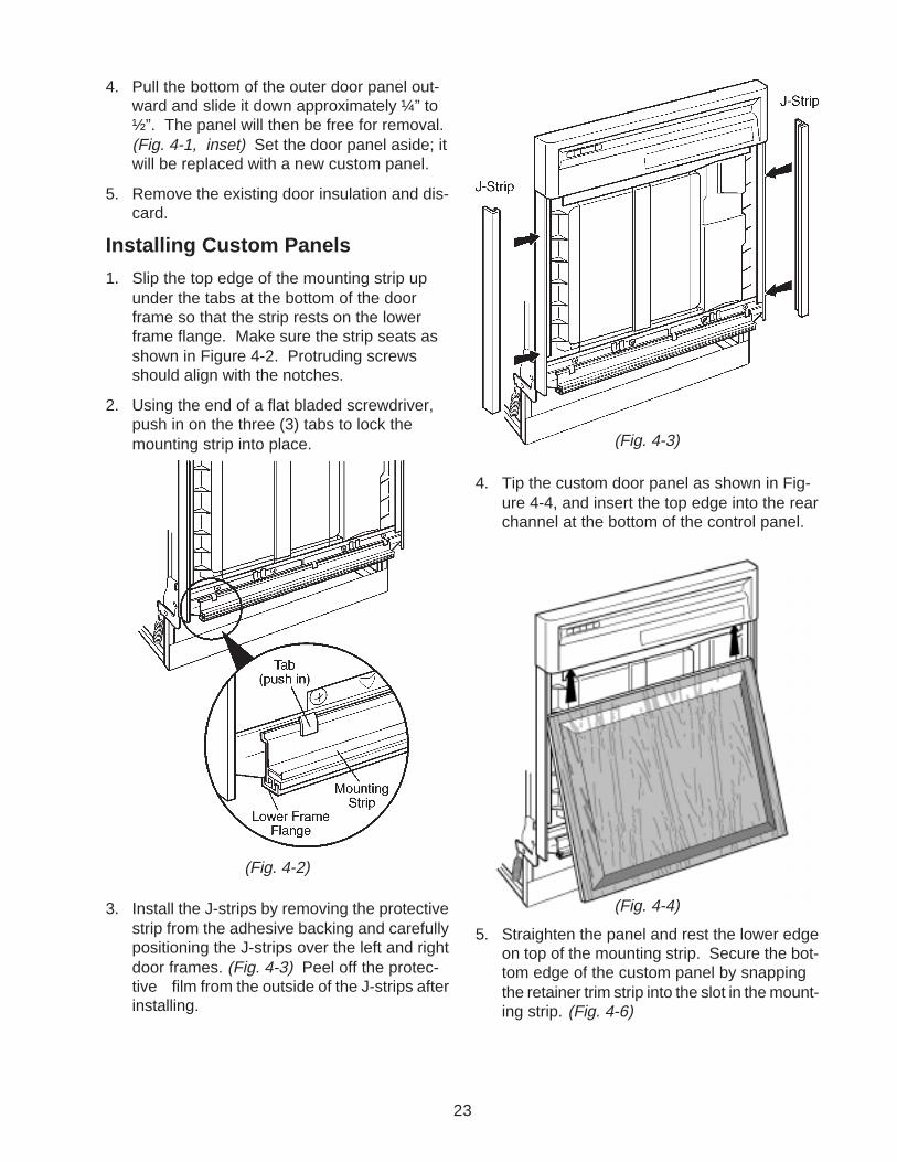
4. Pull the bottom of the outer door panel out-ward and slide it down approximately ¼” to½”. The panel will then be free for removal.(Fig. 4-1, inset) Set the door panel aside; itwill be replaced with a new custom panel.
5. Remove the existing door insulation and dis-card.
Installing Custom Panels
1. Slip the top edge of the mounting strip upunder the tabs at the bottom of the doorframe so that the strip rests on the lowerframe flange. Make sure the strip seats asshown in Figure 4-2. Protruding screwsshould align with the notches.
2. Using the end of a flat bladed screwdriver,push in on the three (3) tabs to lock themounting strip into place.
3. Install the J-strips by removing the protectivestrip from the adhesive backing and carefullypositioning the J-strips over the left and rightdoor frames. (Fig. 4-3) Peel off the protec-tive film from the outside of the J-strips afterinstalling.
4. Tip the custom door panel as shown in Fig-ure 4-4, and insert the top edge into the rearchannel at the bottom of the control panel.
5. Straighten the panel and rest the lower edgeon top of the mounting strip. Secure the bot-tom edge of the custom panel by snappingthe retainer trim strip into the slot in the mount-ing strip. (Fig. 4-6)
(Fig. 4-2)
(Fig. 4-3)
(Fig. 4-4)

24
6. Place the access panel front side down. In-stall the metal access panel extension into theslot it the access panel by pushing down firmlyuntil the extension snaps into place. (Fig. 4-7)
7. Remove the adhesive backing from the ac-cess panel insulation and press the insula-tion firmly into place. (Fig. 4-8)
8. Set the access panel upright. Slide the cus-tom panel down into the bottom and side slots.(Fig. 4-9)
9. Secure the custom panel by inserting tabs onthe panel retainer into the notches along thetop back surface of the access panel. Pressfirmly on the forward edge of the retainer tosnap it into place. (Fig. 4-10)
10. (Refer to Fig. 4-1 on page 71) Install the ac-cess panel assembly to the dishwasher byaligning the slots in the back flange of theextension over the two (2) screw heads pro-truding from the toe panel. Slide the accesspanel downward and tighten the screws.
IMPORTANT
Be sure the door panel is insertedinto the rear channel. (Fig. 4-5)
Retainer
Trim Strip
(Fig. 4-5)
Access Panel
Retainer
Access Panel
Access Panel
Extension
Insulation
(Fig. 4-6)
11. Reinstall the two (2) access panel screws re-moved earlier to secure the access panel tothe dishwasher. Tighten the right screw first,then the left.
(Fig. 4-7)
(Fig. 4-8)
(Fig. 4-9)
(Fig. 4-10)

25
Installing Heavy Duty Door Springs
Standard door springs may need to be replaced by heavy duty springs designed to compensate forthe increased weight of the door resulting from the installation of custom panels. Perform the followingtests to determine whether the heavy duty springs need to be installed.
Heavy Duty Door Spring Kit:
Kit contains two (2) heavy duty door springs and instruction sheet.Kit P/N 3379643
Door Operation Test:
• Springs should have enough tension to assist in closing the heavier door.
• Door should open evenly, without excessive speed which would cause it to drop abruptly.
• Door should remain fully open without closingby itself.
1. If these operation tests are failed and the dishwasher is already installed under the counter,remove the unit from its installed position.
2. Move the lower hook on each of the standarddoor springs to the farthest adjustment slot toincrease spring tension. Repeat the Door Op-eration Tests. If the operation tests again fail,the heavy duty springs supplied must be used.
3. Close and lock the dishwasher door. Removea spring from one side by releasing the lowerhook from the adjustment slot first, then disen-gaging the upper hook from the door hingebracket. (Fig. 4-11)
4. Install a heavy duty spring. Insert the smaller hook through the door hinge bracket first, thenengage the larger hook in the first notch of the second group of adjustment slots. (Fig. 4-11)
5. Repeat steps 3 and 4 to replace the spring on the opposite side of the door.
6. Open and close the door several times. The door should open and close easily. If the door closestoo quickly, decrease the spring tension by moving the lower hook of each spring one (1) notchtoward the back of the dishwasher. Springs should be in the same position on the left and rightsides. Perform the Door Operation Tests again. Continue to adjust the door spring tension asnecessary until the Door Operation Tests confirm proper spring adjustment.
7. Install the dishwasher in the final installed position by following the installation instructions pro-vided with the unit.
Door Hinge
Bracket
Spring
Lower End
Adjustment
Slots
Fig. 4-11

26
INSTALLING THE FLOOR MOUNTING KIT
KIT CONTENTS (P/N 4378968):2 P/N 9743463 Brackets (Fig. 4-12)1 P/N 4378974 Instruction Sheet
INSTALLATION INSTRUCTIONS
1. Loosen the two (2) screws below the access paneland remove the two (2) screws above the accesspanel. (Fig. 4-13)
2. Carefully slide the access panel upward and off thetwo (2) screws below the access panel.
3. Remove the two (2) lower screws securing the toe panel to remove the toe panel from the dishwasher.
4. Position the dishwasher in its final installed position. Refer to the dishwasher installation instruc-tions for the proper installed position.
5. Place the floor mounting bracketsso the top of the bracket hooks overthe top of the dishwasher side bracetowards the back of the unit. (Fig. 4-14)
6. Mark the location of the mounting holeson the floor.
7. Remove the dishwasher and drill two (2) holes,on each side of the dishwasher location.
8. Position the dishwasher in its final installed position and install the floor mounting brackets andsecure them in place with screws.
NOTE
The size of the holes drilled in the floor will depend on the sizeof the hardware (screws) being used for the installation.
9. Reinstall the dishwasher by following the installation instructions provided with the unit.
10. Install the toe panel and the access panel by reversing steps 1 through 3.
Fig. 4-12
Fig. 4-13
Fig. 4-14
FloorBracket

27
WHIRLPOOLDishwasher Warranty
LENGTH OR WARRANTY
FULL ONE-YEARWARRANTYFROM DATE OFPURCHASE
LIMITED ONE-YEARWARRANTYSECOND YEARFROM DATE OFPURCHASE
LIMITED FOUR-YEARWARRANTYSECOND THROUGHFIFTH YEAR FROMDATE OF PURCHASE
FULL TWENTY-YEARWARRANTYFROM DATE OFPURCHASE
FSP™ replacement parts and repair labor to current defectsin materials or workmanship. Service must be provided byan authorized Whirlpool service company.
FSP™ replacement parts for any part of the POWER CLEAN® filtermodule washing system if defective in materials or workmanship.These parts are shown on page 29.
FSP™ replacement parts for Electronic Control system if defectivein materials or workmanship.
For models with dishracks that are oyster-colored, FSP™ replace-ment parts for the top and/or bottom dishracks if they rust due todefective materials or workmanship.
FSP™ replacement parts and repair labor for the DURAPERM®
tub and/or inner door should they fail to contain water due to de-fective materials or workmanship. Service must be provided by anauthorized Whirlpool service company.
WHIRLPOOL WILL NOT PAY FORA. Service calls to:
1. Correct the installation of the dishwasher.2. Instruct you how to use the dishwasher.3. Replace house fuses or correct house wiring or plumbing.
B. Repairs when dishwasher is used in other than normal, single-family household use.C. Pickup and delivery. This product is designed to be repaired in the home.D. Damage to dishwasher caused by accident, misuse, fire, flood, acts of God or use of
products not approved by Whirlpool.E. Any labor costs during limited warranty.F. Repairs to parts or systems resulting from unauthorized modifications made to the appliance.G. In Canada, travel or transportation expenses for customers who reside in remote areas.
WHIRLPOOL CORPORATION AND INGLIS LIMITED SHALL NOT BE LIABLE UNDERTHIS WARRANTY FOR INCIDENTAL OR CONSEQUENTIAL DAMAGES.Some states and provinces do not allow the exclusion or limitation of incidental or conse-quential damages, so this exclusion or limitation may not apply to you. This warranty givesyou specific legal rights, and you may also have other rights which vary from state to stateor province to province.
Outside the United States and Canada, a different warranty may apply. For details,please contact your authorized Whirlpool dealer.
In you need service, first see the “Troubleshooting” section of this book. After checking“Troubleshooting,” additional help is available by calling our Consumer Assistance Centertelephone number, 1-800-253-1301, from anywhere in the U.S.A. In Canada, you may callyour Inglis Limited Appliance Service Branch.
WHIRLPOOL WILL PAY FOR
28

29
SERIAL PLATE LOCATOR
SERIAL NUMBER DESIGNATORSERIAL NUMBER
MANUFACTURING SITEF = Findlay, OH
YEAR OF MANUFACTUREG = 1997H = 1998
WEEK OF MANUFACTURE18 = 18th Week
PRODUCT SEQUENCE NUMBER
F G 18 70352
MODEL NUMBER DESIGNATORMANUFACTURING NUMBER
MARKETING CHANNEL (if present)
PRODUCT GROUPD = DishwasherG = Gold Line Dishwasher
PRODUCT IDENTIFICATIONP = PortableU = Undercounter
FEATURES4 = Advertising Model8 = Soil Settler9 = Power Clean
FEATURES00 = Rocker Switch (Soil Settler) or
5 Push Button (Power Clean)20 = 7 Push Button40 = 4 Push Button (Soil Settler) or
9 Push Button (Power Clean)60 = 10 Push Button80 = 11 Push Button
FEATURESDW = Durawash/Soil SettlerPF = Power Filter/Tower FeedSC = Power Filter/Internal Feed
YEAR OF INTRODUCTIONG = 1998
COLOR CODE
ENGINEERING CHANGE (Numeric)
D U 9 20 PF G
SERIAL/MODEL NUMBER PLATE
N 0

30
CONTACT INFORMATIONFor Product Specifications and Warranty Information Sources:
1-800-874-4698For Technical Assistance:
1-800-253-2870For Service Manuals and other Service Literature:
1-800-851-4605For Service Replacement Parts:
1-800-259-7278For Safety Related Information:
1-800-541-5746

V

VI
CORPORATION