1996+Chevy+Express+Gmc+Savana+Collision+Repair+Issues
32
1996 CHEVY EXPRESS/GMC SAVANA COLLISION REPAIR ISSUES Table of Contents Panel Identification 2 Radiator Support Assembly 3 Front Inner Fender 5 Door Service 7 Door Frame Opening 8 Roof Panel 12 Quarter Panel 14 Rear Outer Wheelhouse 18 Rear Door Hinge Pillar 20 Floor Rear Extension 22 Magnesium Instrument Panel Support 24 Body Dimensions 26 Frame Dimensions 31 Appendix: Specifications 32
-
Upload
javi-chito -
Category
Documents
-
view
37 -
download
1
Transcript of 1996+Chevy+Express+Gmc+Savana+Collision+Repair+Issues

1 9 9 6 C H E V Y E X P R E S S / G M C S A V A N A C O L L I S I O N R E P A I R I S S U E S 11996 CHEVY EXPRESS / GMC SAVANA COLLISION REPAIR ISSUES
Table of Contents
Panel Identification2
Radiator Support Assembly3
Front Inner Fender5
Door Service7
Door Frame Opening8
Roof Panel12
Quarter Panel14
Rear Outer Wheelhouse18
Rear Door Hinge Pillar20
Floor Rear Extension22
Magnesium Instrument Panel Support24
Body Dimensions26
Frame Dimensions31
Appendix: Specifications32

2 1 9 9 6 C H E V Y E X P R E S S / G M C S A V A N A C O L L I S I O N R E P A I R I S S U E S
1. Panel Identification
TPO
TPO
TPO
TPO
Pri
mar
ily T
SGS
AB
SSM
C
SMC
XENO
Y=
Tw
o-S
ided
Gal
van
ized
Ste
el
=H
igh
-Str
eng
th L
ow
-All
oy
Stee
l
=P
last
ics
TP
O=
Ther
mo
pla
stic
Ole
fin
SM
C=
Shee
t M
old
ed C
om
po
un
d
XENO
Y=
Xen
oy
AB
S=
Acr
ylo
nit
rile
/Bu
tad
ien
e/St
yren
e
G119
51.1
Pai
nte
d
Ch
rom
ed Fro
nt
and
Rea
rSt
ep P
ads

1 9 9 6 C H E V Y E X P R E S S / G M C S A V A N A C O L L I S I O N R E P A I R I S S U E S 3
2. Radiator Support Assembly
The radiator support assembly is madeof a composite material (SMC) toreduce weight and simplify installation
procedures. The radiator support bolts on andis positioned by tabs which are located intoholes in the front-end lower tie bar (figure2-1). A steel reinforcement extends across theupper portion. This reinforcement is part ofthe assembly or available separately (figure2-2). It is attached to the radiator support by14 rivets. Replacement rivets are available asGM Part #10263118.
Figure 2-1:Bolt-On Radiator Support Assembly
Figure 2-2
G11952.1
G11952.2

4 1 9 9 6 C H E V Y E X P R E S S / G M C S A V A N A C O L L I S I O N R E P A I R I S S U E S
R A D I A T O R S U P P O R T A S S E M B L Y
Lower Tie-BarThe lower tie bar is serviced as a separateassembly and includes the radiator supportbody mount reinforcements. It is replaced atthe factory seams and is plug welded to thefront fender braces. The lower tie-bar is boltedthrough the body mounts and onto the frame(figure 2-3). The body mount bolts are torquedto 85 N.m (63 ft-lbs).
Lower Tie-Bar Fender BraceThe fender braces are available for the left andright sides, and serviced as separate components.The fender braces attach the front inner fenderpanel to the lower radiator support tie-bar withfactory spot welds (figure 2-3).
Figure 2-3
Lower Tie-Bar
Fender Brace
G11952.3
1 9 9 6 C H E V Y E X P R E S S / G M C S A V A N A C O L L I S I O N R E P A I R I S S U E S 5
R U N N I N G H E A D3. Front Inner Fender
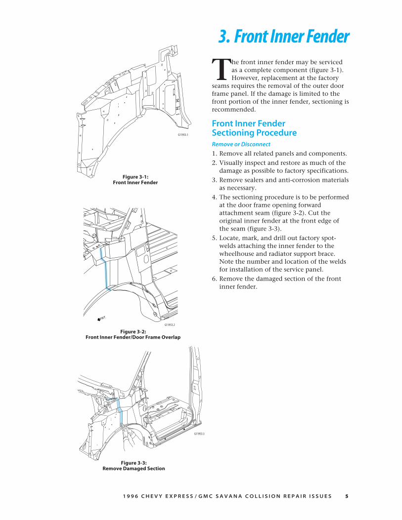
The front inner fender may be servicedas a complete component (figure 3-1).However, replacement at the factory
seams requires the removal of the outer doorframe panel. If the damage is limited to thefront portion of the inner fender, sectioning isrecommended.
Front Inner FenderSectioning ProcedureRemove or Disconnect
1. Remove all related panels and components.
2. Visually inspect and restore as much of thedamage as possible to factory specifications.
3. Remove sealers and anti-corrosion materialsas necessary.
4. The sectioning procedure is to be performedat the door frame opening forwardattachment seam (figure 3-2). Cut theoriginal inner fender at the front edge ofthe seam (figure 3-3).
5. Locate, mark, and drill out factory spot-welds attaching the inner fender to thewheelhouse and radiator support brace.Note the number and location of the weldsfor installation of the service panel.
6. Remove the damaged section of the frontinner fender.
Figure 3-3:Remove Damaged Section
Figure 3-1:Front Inner Fender
FRT
G11953.2
Figure 3-2:Front Inner Fender/Door Frame Overlap
G11953.1
G11953.3

6 1 9 9 6 C H E V Y E X P R E S S / G M C S A V A N A C O L L I S I O N R E P A I R I S S U E S
Install or connect
1. Align the template provided with theservice part, mark and cut it according toinstructions, which are also provided withthe part. The service inner fender must becut to overlap the door frame opening25mm (1␣ inch) (figure 3-4).
2. Temporarily position the service part overthe door frame weld flange. At the hoodhinge mounting area, the service part mustbe installed under the upper cowl panel andover the door frame opening weld flange(figure 3-5). Check for proper fit andalignment, also make sure there is a flush fitat the door frame weld flange.
— Notice —The sectioned service part
must be modified slightly to fit flush at thesectioning seam, and at the upper cowl panel
and door frame opening weld flange.
3. Remove service part and drill 8mm(5⁄16␣ inch) holes for plug welding as notedfrom the original panel and along thesectioning joint 13mm (1⁄2␣ inch) from thecut edge.
4. Install and position the modified servicepart according to body dimensions usingthree-dimensional measuring equipment.Plug weld accordingly, using frequentmeasurements to ensure accurate fit andalignment to adjacent panels.
5. Clean and prepare all surfaces. Prime withtwo-part catalyzed primer. Apply sealersand anti-corrosion protection materials asnecessary. Do not combine paint systems.Refer to paint manufacturer’srecommendations.
— Notice —Be sure to apply seam sealer to both sides of
the sectioning joint (figure 3-6).
6. Install all related panels and components.
F R O N T I N N E R F E N D E R
Figure 3-6:Seam Sealer
Figure 3-5:Check for Proper Fit
G11953.4
G11953.5
G11953.6
Figure 3-4:Modified Service Part

1 9 9 6 C H E V Y E X P R E S S / G M C S A V A N A C O L L I S I O N R E P A I R I S S U E S 7
4. Door Service
Figure 4-1:Doors
The doors are serviced as completeassemblies, or the outer door panels maybe serviced separately. Use conventional
service procedures when repairing the doors.The sliding side door features bolt-on hinges,while the front doors, the 60/40 side doors, andthe rear doors all feature weld on hinges. All sidedoors have HSLA door beams (figure 4-1).
G11954.1

8 1 9 9 6 C H E V Y E X P R E S S / G M C S A V A N A C O L L I S I O N R E P A I R I S S U E S
5. Door Frame OpeningDoor Frame OpeningGeneral Sectioning ProcedureWhen sectioning the door frame opening inareas where there is no inner reinforcement, a100mm (4␣ inch) backing plate must be usedbehind the joint to ensure a solid and secureweld. Backing plates can be cut from theunused portion of the door frame openingservice part. The specific areas to be sectionedare determined by the extent of damage to thevehicle.
— Notice —Sectioning should take place
only in recommended areas (figure 5-1).Failure to do so may compromise the
structural integrity of the vehicle.
— Important —This procedure does not apply to the front hinge
pillar; see front hinge pillar sectioning procedures.
Remove or Disconnect
1. Remove all related panels and components.
2. Visually inspect and restore as much of thedamage as possible to factory specifications.
3. Note location of the sealers, sounddeadeners, and anti-corrosion materials andremove as necessary.
4. After pulling and straightening operationshave been completed, and before thedamaged panel is removed, check, measure,and compare the service part with thedamaged part to choose the areas wheresectioning can best be performed.
5. Cut the door frame opening wheresectioning is to be performed (see figure5-1). Do not damage the inner panels orreinforcements.
6. Locate, mark, and drill out all factory welds.Note the number and location of welds forinstallation of the service part.
7. Remove the damaged area of the doorframe opening.
SECTIONING SHOULDTAKE PLACE ONLY INTHE SHADED AREAS.
Figure 5-1:Driver and Passenger Door Frames
G11955.1

1 9 9 6 C H E V Y E X P R E S S / G M C S A V A N A C O L L I S I O N R E P A I R I S S U E S 9
Door Frame Opening GeneralSectioning Procedures (con’t)
Install or Connect
1. On the service part, mark a horizontal lineto leave a gap of one and one-half times thethickness of the metal at the sectioningjoint. Cut the outer door frame openingservice part along this line.
2. Cut a 100mm (4␣ inch) piece from theunused portion of the service part for abacking plate. Remove the flange on eachside of the backing plate so that it will fitbehind the sectioning joint.
3. Drill 8mm (5⁄16␣ inch) holes for plug weldingin the service part in locations noted fromthe original panel. Also, drill holes for plugwelding along the sectioning cuts on boththe service part and the original panel.Locate these holes approximately 25mm(1␣ inch) from the edge of the sectioningcuts.
4. Prepare mating surfaces and position thebacking plates with 50mm (2␣ inches) of thebacking plate exposed, and plug weld.Position the service part to overlap theexposed 50mm (2␣ inches) of the backingplate, check fit using three-dimensionalmeasuring equipment, and plug weldaccordingly (figure 5-2).
5. Stitch weld along the sectioning joint.Make 25mm (1␣ inch) welds along the seamwith 25mm (1␣ inch) gaps between. Then goback and complete the stitch weld. This willcreate a solid joint with minimal heatdistortion.
6. Clean and prepare welded surfaces. Primewith two-part catalyzed primer.
7. Install sealers, sound deadeners, and foambaffles in the service door frame opening asnoted from the removal procedures (figure5-3). Apply anti-corrosion protectionmaterials, as necessary. Do not combinepaint systems. Refer to paint manufacturer’srecommendations.
8. Install all related panels and components.
D O O R F R A M E O P E N I N G
FRT
Figure 5-2:Align Panels and Weld Accordingly
Figure 5-3:Lock Pillar Foam Baffle
Gas Door Pocket
100mm
G11955.2
G11955.3

1 0 1 9 9 6 C H E V Y E X P R E S S / G M C S A V A N A C O L L I S I O N R E P A I R I S S U E S
Outer Front Lower Hinge PillarSectioning ProcedureThe hinge pillar inner reinforcement can beused as a backing plate when sectioning theouter door frame at the front hinge pillar(figure 5-4).
Remove or Disconnect
1. Remove all related panels and components.
2. Visually inspect and restore as much of thedamage as possible to factory specifications.
3. Remove sealers and anti-corrosion materialsas necessary.
4. Align template provided with the servicepart, mark and cut the hinge pillar forsectioning. NOTE: When attaching thetemplates to the hinge pillar, use 3M’sRepositionable Adhesive (part #06091), oran equivalent non-permanent sprayadhesive.
— Caution —Use care not to cut the inner panels and
reinforcements when cutting the outer panels.
5. Perform all other sectioning procedures asnecessary.
6. Locate, mark, and drill out all factory weldsattaching the lower front door hinge pillar.Note the number and location of welds forinstallation of the service part.
7. Remove damaged front lower hinge pillar,remove foam from the lower portion of thehinge pillar (figure 5-5).
D O O R F R A M E O P E N I N G
Figure 5-5:Foam Baffles
Figure 5-4:Use Reinforcement as Backing Plate
G11955.4
G11955.3

1 9 9 6 C H E V Y E X P R E S S / G M C S A V A N A C O L L I S I O N R E P A I R I S S U E S 1 1
Outer Front Lower Hinge PillarSectioning Procedures (con’t)
Install or Connect
1. Rough cut the service part to match thedamaged section of the door frame openingand discard the unused portion of theservice part.
2. The modified service panel should betrimmed to allow a gap of 11/2 times themetal thickness at the joint between theservice part and the factory part (figure 5-6).
D O O R F R A M E O P E N I N G
3. Drill 8mm (5⁄16␣ inch) holes for plug weldingin the service part 13mm (1⁄2 inch) from thesectioning joint edge (figure 5-7). Drill8mm (5⁄16␣ inch) holes for plug welding inthe service panel as necessary in thelocations noted from the original panel.
4. Prepare mating surfaces as necessary. Alignthe service part to the vehicle, check fitusing three-dimensional measuringequipment and plug weld accordingly.
5. Complete the sectioning by welding thejoint gap closed with 25mm (1␣ inch) weldsalong the seam with 25mm (1␣ inch) gapsalternately. Then go back and complete thestitch weld. This will create a solid jointwith minimal heat distortion.
6. Install closed cell two-part expandable foamin the service door frame opening hingepillar as necessary to replace the originalfoam air baffle (see figure 5-5).
7. Clean and prepare welded surfaces. Primewith two-part catalyzed primer. Applysealers and corrosion protection materialsas necessary. Do not combine paintsystems. Refer to paint manufacturer’srecommendations.
8. Install all related panels and components.
Figure 5-6:Trim for Proper Fit
Figure 5-7:Install Modified Panel
G11955.7
G11955.6

1 2 1 9 9 6 C H E V Y E X P R E S S / G M C S A V A N A C O L L I S I O N R E P A I R I S S U E S
6. Roof Panel
The roof panel consists of a single layerouter panel. The original panel isremoved by cutting the panel to leave
the side weld flanges attached at the “driprail.” The service panel is not modified forinstallation other than drilling holes forplug welding. These procedures have beendeveloped to simplify roof panel replacement(figure 6-1).
Remove or Disconnect
1. Remove all related panels and components.
2. Visually inspect and restore as much of thedamage as possible to factory specifications.
3. Remove sealers and anti-corrosion materialsas necessary. To remove the seam sealeralong the “drip rails” use 3M Scotch BriteClean and Strip Discs (part # 7460) orequivalent.
4. Using a panel cutter, cut the sides of theoriginal roof panel at the floor of the “driprail” leaving the weld flange attached to theroof rail reinforcement (figure 6-2).
5. From inside the vehicle, and with theheadliner removed, cut the roof panel fromthe support bows using a windshieldadhesive cutting tool, such as wire cuttingtool, or equivalent.
— Notice —Use care when cutting roof panel
not to cut the panels and reinforcementsunder the original panel.
6. Locate, mark, and drill out the factory spotwelds attaching the roof panel at the frontwindshield pinch-weld flange and rear doorframe opening pinch-weld flange.
7. Remove damaged roof panel.
Figure 6-1:Roof Panel
Figure 6-2:Cutting Roof Panel in Floor of Drip Rail
Quarter Panel
Roof
Reinforce.
G11956.1
G11956.2

1 9 9 6 C H E V Y E X P R E S S / G M C S A V A N A C O L L I S I O N R E P A I R I S S U E S 1 3
Install or Connect
1. Prepare mating surfaces and check forproper fit and alignment. It may benecessary to grind the lip remaining at theweld flange for a proper fit of the serviceroof panel (figure 6-3).
R O O F P A N E L
2. Drill 8mm (5⁄16␣ inch) holes for plug weldingin the service panel along the side-rail weldflanges (figure 6-4), the front windshieldpinch-weld flanges, and the rear door frameopening pinch-weld flanges 62mm(21⁄2␣ inches) apart.
3. Apply anti-corrosion materials to baremetal weld flanges as necessary. Apply anti-flutter material to roof support bows.
— Important —The type of anti-flutter materialused on the bows will determinewhether it is to be applied before
or after the roof panel is installed.
4. Position the service panel, check for properfit and plug weld as necessary.
5. Clean and prepare all surfaces. The bondingarea should be a primer surface ONLY,and NOT an aftermarket top coated (paint,or color coated) surface. Materials such asBASF DE17, Dupont 2610, or PPG DP40,or equivalent, are appropriate for thisapplication (figure 6-5).
— Notice —Refer to Service Bulletin #43-10-48
for more detailed information.
6. Apply sealers and anti-corrosion materialsas necessary. Do not combine paintsystems. Refer to manufacturer’srecommendations.
7. Install all related panels and components.
Figure 6-5:Tape Off Windshield-Pinch Weld Flange Before Top Coating
Figure 6-4:Drill 13mm (1⁄2 inch) From Outer Edge
Figure 6-3:Cross-Section of Roof Structure
G11956.3
G11956.4
G11956.5

1 4 1 9 9 6 C H E V Y E X P R E S S / G M C S A V A N A C O L L I S I O N R E P A I R I S S U E S
Quarter PanelSectioning Procedure
Cargo VanThe quarter panel service part is supplied asa complete panel and should be replaced asa complete panel only in the event the roofpanel and upper side rail are to be replaced.Sectioning procedures have beendeveloped to allow the replacement of thequarter panel without the removal of theroof panel (figure 7-1).
Remove or Disconnect
1. Remove all related panels andcomponents.
2. Visually inspect and restore as much ofthe damage as possible to factoryspecifications.
3. Remove sealers, sound deadeners, andanti-corrosion materials as necessary.
4. Apply 50mm (2␣ inch) wide tape alongthe upper edge of the quarter panel atthe roof line (figure 7-2).
5. Using a panel cutter, cut the quarterpanel at the lower edge of the tape toleave a 50mm (2␣ inch) wide flange of theoriginal quarter panel attached to theside reinforcement rail (figure 7-3).
— Notice —Use care when cutting quarter panel
not to cut the panels and reinforcementsunder the original panel (figure 7-4).
6. Locate, mark, and drill out all factorywelds around the perimeter of thequarter panel as necessary to removedamaged panel. Note number andlocation of welds for installation of theservice panel.
7. Remove damaged quarter panel.
7. Quarter Panel
Figure 7-1:Cargo Van Service Panel
G11957.1
Reseal floor toouter panel
Figure 7-4:Reinforcement and Sealer Locations
Figure 7-2:Section in the Shaded Area
50 mm
Figure 7-3:Locate Area for Sectioning
G11957.4
Roof
Quarter PanelReinforce.
G11957.3
G11957.2

1 9 9 6 C H E V Y E X P R E S S / G M C S A V A N A C O L L I S I O N R E P A I R I S S U E S 1 5
Quarter Panel Sectioning Procedure —Cargo Van (con’t)
Install or Connect
1. Trim and discard the upper mountingflange on the service panel so that it can fitover the 50mm (2␣ inch) tab left from theoriginal panel (figure 7-5)
2. Drill 8mm (5⁄16␣ inch) holes for plug weldingalong top of the quarter panel 25mm(1␣ inch) from top edge, 40mm (11⁄2␣ inches)apart (figure 7-6).
3. Apply anti-corrosion materials to baremetal weld flanges as necessary.
4. Prepare mating surfaces and check forproper fit and alignment, and plug weldaccordingly.
5. Apply 3M’s Ultra Pro Seam Sealer (part#08361) or equivalent to the sectioningjoint. The quarter panel must be sealed atthe floor seam also.
— Caution —The quarter panel must be sealed
at the floor to prevent exhaust gas intrusioninto the vehicle (see figure 7-4).
6. Apply sealer materials and air baffles asnecessary. Clean and prepare all surfaces.Prime with two-part catalyzed primer. Donot combine paint systems. Refer tomanufacturer’s recommendations.
7. Install all related panels and components.
Q U A R T E R P A N E L
Figure 7-5:Modify Service Panel
Figure 7-6:Plug Weld Service Panel Every 40mm (11⁄2 inches)
G11957.5
G11957.6
Reinforce.
Roof
Quarter Panel

1 6 1 9 9 6 C H E V Y E X P R E S S / G M C S A V A N A C O L L I S I O N R E P A I R I S S U E S
Passenger VanThe quarter panel may be serviced as acomplete panel only in the event the roofpanel and the side rail are to be replaced.Sectioning procedures have been developed tosimplify the repair. The service part can bereplaced by making sectioning cuts at thewindow pillars (figure 7-7).
Remove or Disconnect
1. Remove all related panels and components,including the side glass.
2. Visually inspect and restore as much of thedamage as possible to factory specifications.
3. Remove sealers, sound deadeners, and anti-corrosion protection materials as necessary.
4. Measure within the shaded areas on thepillars and mark the location to cut theoriginal panel. Cut the pillars and windowdividers, taking care not to damage theinner reinforcement panels (figure 7-8).
5. Locate, mark, and drill out all factory weldsaround the perimeter of the quarter panelas necessary to remove the damaged panel.Note the number and location of welds forinstallation of the service panel.
6. Remove damaged quarter panel.
Q U A R T E R P A N E L
Figure 7-7:Passenger Van Service Panel
Figure 7-8:Measure Within the Shaded Areas
G11957.7
G11957.8

1 9 9 6 C H E V Y E X P R E S S / G M C S A V A N A C O L L I S I O N R E P A I R I S S U E S 1 7
Quarter Panel Sectioning Procedure —Passenger Van (con’t)
Install or Connect
1. Fit and align the replacement quarter panelwith adjacent body panels. The sectioningjoint should be trimmed to allow a gap ofone to 11/2 times the metal thickness at thejoint between the service part and theoriginal part.
2. Cut a 100mm (4␣ inch) backing plate fromthe unused portion of the service part. Trimthe backing plate as necessary to fit behindthe sectioning joint. Drill 8mm (5⁄16␣ inch)plug weld holes in the original part 25mm(1␣ inch) from the cut edge. Fit the backingplate halfway into the sectioning joint,clamp and plug weld to vehicle.
3. Drill 8mm (5⁄16␣ inch) plug weld holes inthe service quarter panel as necessary inlocations noted from the original panel.Also drill four plug weld holes in the fuelfiller neck pocket of the service panel forattachment to the inner reinforcementpanel.
4. Prepare all attachment surfaces asnecessary.
5. Align the quarter panel to adjacent panelsand plug weld accordingly (figure 7-9).
6. Complete the sectioning by welding thejoint gap closed with 25mm (1␣ inch) weldsalong the seam with 25mm (1␣ inch) gapsalternately. Then go back and complete thestitch weld. This should create a solid weldwith minimum heat distortion.
7. Clean and prepare all surfaces. The glassbonding area should be a primer surfaceONLY, and NOT an aftermarket top coated(paint, or color coated) surface. Materialssuch as BASF DE17, Dupont 2610, or PPGDP40, or equivalent, are appropriate for thisapplication (figure 7-10).
— Notice —Refer to Service Bulletin #43-10-48
for more detailed information.
— Caution —The quarter panel must be sealed
at the floor to prevent exhaust gas intrusioninto the vehicle (see figure 7-4).
8. Apply sealers and anti-corrosion materialsas necessary. Do not combine paintsystems. Refer to manufacturer’srecommendations.
9. Install all related panels and components.
100mm
Q U A R T E R P A N E L
Figure 7-10:Stationary Glass Bonding
BONDED
BONDED
VENTED
Figure 7-9:100mm (4 inch) Backing Plate
G11957.9
G11957.10

1 8 1 9 9 6 C H E V Y E X P R E S S / G M C S A V A N A C O L L I S I O N R E P A I R I S S U E S
8. Rear Outer Wheelhouse
Figure 8-2:Apply 25mm (1 inch) Tape
Figure 8-3:25mm (1 inch) Weld Flange
G11958.1
G11958.2
G11958.3
Figure 8-1:Rear Outer Wheelhouse
R ear outer wheelhouse sectioningprocedures have been developed tosimplify repair when damage is
limited to the outer wheelhouse. In the eventthe inner wheelhouse is to be replaced, installouter wheelhouse service panel at factoryseams (figure 8-1).
Remove or Disconnect
1. Remove all related panels and components,including the quarter panel.
2. Visually inspect and restore as much of thedamage as possible.
3. Remove sealers, sound deadeners, and anti-corrosion materials as necessary.
4. Apply a strip of 25mm (1␣ inch) maskingtape along the flange of the outerwheelhouse (figure 8-2).
5. Locate, mark, and drill out all factory spotwelds attaching the front and rear lowersections of the outer wheelhouse to thevehicle.
6. Cut along the outboard side of the maskingtape to leave a 25mm (1␣ inch) tab attachedto the inner wheelhouse (figure 8-3).
7. Remove the damaged outer wheelhouse.

1 9 9 6 C H E V Y E X P R E S S / G M C S A V A N A C O L L I S I O N R E P A I R I S S U E S 1 9
Install or Connect
1. Cut the wheelhouse service part along thecorner of the bend to remove the down-turned weld flange (figure 8-4).
2. On the service part drill 8mm (5⁄16␣ inch)holes for plug welding every 40mm(11⁄2␣ inches) along the cut edge.
3. Prepare mating surfaces as necessary.Position the service part, checking forproper fit, and plug weld accordingly(figure 8-5).
4. Clean and prepare the welded surfaces.Prime with two-part catalyzed primer.Apply sealers and anti-corrosion materialsas necessary. Do not combine paintsystems. Refer to paint manufacturer’srecommendations.
5. Install all related panels and components.Figure 8-4:Modify Service Part
R E A R O U T E R W H E E L H O U S E
Figure 8-5:Plug Weld Every 40 mm (11⁄2 inches)
G11958.4
G11958.5

2 0 1 9 9 6 C H E V Y E X P R E S S / G M C S A V A N A C O L L I S I O N R E P A I R I S S U E S
The rear door hinge pillar service part isserviced as an assembly (figure 9-1), whichconsists of the door hinge pillar outer panel
and the inner anchor plate reinforcement. Thereinforcement includes weld nuts for attaching therear door bolt-on hinges.
Remove or Disconnect
1. Remove all related trim panels and components.
2. Visually inspect and restore as much of thedamage as possible to factory specifications.
3. Remove sealers, sound deadeners, and anti-corrosion materials as necessary.
4. The rear door hinge pillar is to be sectioned inthe area of the pressure relief valve opening(figure 9-2). Measure within the shaded area onthe rear pillar. Mark and cut the original panel,use care not to damage inner panels (figure 9-3).
5. Locate, mark, and drill out all factory spot weldsaround the perimeter of the rear door hingepillar below the sectioning joint.
6. Remove the damaged rear hinge pillar.
9. Rear Door Hinge Pillar
Figure 9-1:Service Assembly
FRT
Figure 9-2:Section Pillar Within Shaded Area
Figure 9-3:Use Care Not to Damage Inner Panels
G11959.1
G11959.3G11959.2

1 9 9 6 C H E V Y E X P R E S S / G M C S A V A N A C O L L I S I O N R E P A I R I S S U E S 2 1
Install or Connect
1. Cut a 100mm (4␣ inch) backing plate fromthe unused portion of the service part. Trimthe backing plate as necessary to fit behindthe sectioning joint. Drill 8mm (5⁄16␣ inch)plug weld holes in the original part 25mm(1␣ inch) from the cut edge. Fit the backingplate halfway into the sectioning joint,clamp and plug weld to the vehicle(figure 9-4).
2. Fit and align service hinge pillar withadjacent body panels. The sectioning jointshould be trimmed to allow a gap of 11/2
times the metal thickness at the jointbetween the service part and the originalpart. Take care to ensure proper alignmentof service panels.
3. Drill 8mm (5⁄16␣ inch) plug weld holes in theservice hinge pillar as necessary in locationsnoted from the original panel.
4. Prepare all attachment surfaces asnecessary.
5. Align the service part to the vehicle (figure9-5), check fit using three-dimensionalmeasuring equipment and plug weldaccordingly.
6. Complete sectioning by welding the jointgap closed with 25mm (1␣ inch) welds alongthe seam with 25mm (1␣ inch) gapsalternately. Then go back and complete thestitch weld. This will create a solid jointwith minimal heat distortion.
7. Clean and prepare the welded surfaces.Prime with two-part catalyzed primer.Apply fillers, sealers, and corrosionprotection materials as necessary. Do notcombine paint systems. Refer to paintmanufacturer’s recommendations.
8. Install all related panels and components.
Figure 9-4:Install Backing Plates
R E A R D O O R H I N G E P I L L A R
Figure 9-5:Install Service Part
G11959.5
G11959.4

2 2 1 9 9 6 C H E V Y E X P R E S S / G M C S A V A N A C O L L I S I O N R E P A I R I S S U E S
10. Floor Rear Extension
The floor rear extension panel is servicedas a single component. The reinforce-ment structure for the floor panel is
a separate part and can only be servicedseparately. In most cases, this reinforcementwill need to be replaced in the event the floorpanel extension is to be replaced (figure 10-1).
Remove or Disconnect
1. Remove all related panels and components,including jack stowaway mount in rightrear corner of vehicle.
2. Visually inspect and restore as much of thedamage as possible to factory specifications.
3. Remove sealers, sound deadeners, and anti-corrosion materials as necessary.
4. Locate, mark, and drill out factory weldsnecessary to remove the extension panel.NOTE: The rear corners of the originalpanel must be cut to remove the panel fromthe vehicle.
— Important —If a rear door hinge pillar inner reinforcementis to be replaced it is not necessary (though it
may be easier) to perform step #5.
5. Loosen all body to frame mount bolts,remove all but the two in the radiator coresupport and the two front body bolts. Liftbody off the frame, place 4x4 wood blocksto support the body as in (figure 10-2).
6. Locate, mark, and drill out welds to removethe body mount anchor plates and the floorpanel reinforcement. Remove the foam airbaffles from the right and left floorextensions (figure 10-3), these need to bereinstalled during assembly.
FRT
FRT
Figure 10-2:Support Body for Service Figure 10-3:
Foam Location
Exterior Panel
G119510.2
G119510.1
Figure 10-1:Service Panels
Body MountReinforcement Plates
Body MountReinforcement Plate
G119510.3

1 9 9 6 C H E V Y E X P R E S S / G M C S A V A N A C O L L I S I O N R E P A I R I S S U E S 2 3
Install or Connect
1. Drill holes for plug welding as necessary toinstall the service panels. Clean and prepareall mating surfaces as necessary.
2. Locate reinforcement and body anchorpanels using three-dimensional measuringequipment and plug weld as necessary.
3. Cut and bend each side of the floor panelextension as shown in figure 10-4, placethe front edge of the extension panel inposition first, then bring the rear of theservice part into place and straighten thebent tabs.
4. Check for proper fit and alignment andweld accordingly, including cuts made forinstallation.
5. Lower body to frame and reattach bodyto frame mounts, torque bolts to 85 N.m(63 ft-lbs).
6. Clean and prepare welded surfaces. Primewith two-part catalyzed primer. Drillappropriate size holes to install two-partexpanding foam in the floor extension(figure 10-5). Be sure to seal the holes witha suitable plug.
7. Apply sealers and anti-corrosion materialsas necessary. Do not combine paintsystems. Refer to manufacturer’srecommendations.
8. Install all related panels and components.
F L O O R R E A R E X T E N S I O N
FRT
Figure 10-4:Modified Service Panel
Figure 10-5:Foam Application
Apply expandable foam inthese locations.
G119510.4
G119510.5

2 4 1 9 9 6 C H E V Y E X P R E S S / G M C S A V A N A C O L L I S I O N R E P A I R I S S U E S
11. Magnesium Instrument Panel Support
Figure 11-1
This component is a one-piece, die-castmagnesium instrument panel support.It functions as a structural cross-vehicle
beam, air-bag support, instrument panelcarrier, steering column mounting bracket,and consolidates as many as thirty differentsteel and plastic components (figure 11-1).
TORQUE MOUNTING BOLTSTO 50 N.M.
G119511.1

1 9 9 6 C H E V Y E X P R E S S / G M C S A V A N A C O L L I S I O N R E P A I R I S S U E S 2 5
The magnesium beam is designed to deformand absorb energy generated by a severeimpact. Under no circumstance is themagnesium beam to be repaired in any way.If any of the following conditions are presentafter a collision, the magnesium beammust be replaced:• If gaps between the dash trim panels are
greater than the build objectives (figure11-2)
• If both air bags are deployed; 10 and 20series
• If the steering column is collapsed, or thesteering wheel requires replacement; 30series
• If there is damage to the lower instrumentpanel, the knee bolster, or the knee bolsterbrackets
A
B
No gap between driver-side knee bolsterand instrument panel trim pad.
Driver-SideKnee Bolster
I/P Panel AssemblyLower Extension/Upper Trim
Passenger-SideKnee Bolster
Cross section View A above
Gap to be4.0mm ± 2.5mm
and parallelwithin 0.5mm
Gap to be2.0mm ± 1.0mm
and parallelwithin 0.5mm
Cross section View B above
I/P panel assemblylower extension/upper trim
to bolster must be flush.
Figure 11-2:Build Objectives – Instrument Panel Tolerances
PassengerAir Bag Module
Door
No gap between top edgeof passenger-side knee bolster,
I/P trim pad, and passengerair bag module door.
3.0mm ± 1.0mmparallel between
passenger knee bolster andair bag module door
M A G N E S I U M I N S T R U M E N T P A N E L S U P P O R T
G119511.2
Passenger-SideKnee Bolster

2 6 1 9 9 6 C H E V Y E X P R E S S / G M C S A V A N A C O L L I S I O N R E P A I R I S S U E S
12. Body DimensionsG
VA
N B
OD
YS
IDE
ALL
DIM
ENSI
ON
S A
RE
MEA
SUR
ED F
RO
M A
ZER
O L
INE,
CEN
TER
LIN
E, A
ND
A C
OM
MO
N D
ATU
M.
ALL
DIM
ENSI
ON
S A
RE
SYM
MET
RIC
AL
UN
LESS
OTH
ERW
ISE
SPEC
IFIE
D.
SEE
PA
GE
30
FO
R H
OLE
IDEN
TIFI
CA
TIO
N.
G119
512.
1
L:18
68W
: 73
3H:
20
52
J
L:38
05W
: 10
02H:
78
0
N
L:21
30W
: 93
2H:
53
5
I
L:10
58W
: 93
2H:
53
5
I
L:24
36W
: 10
05H:
78
0
H
L:24
36W
: 10
04H:
81
9
G
FL:
895
W:
904
H:
1130
BL:
581
W:
823
H:
1362
DL:
1422
W:
964
H:
904
EL:
1413
W:
957
H:
1005
BL:
634
W:
822
H:
1354
AL:
934
W:
816
H:
1249
AL:
1014
W:
824
H:
1006
AL:
983
W:
878
H:
743
CL:
145
W:
896
H:
1118
KL:
2253
W:
861
H:
1189
LL:
2246
W:
899
H:
1366
L:38
05W
: 10
01H:
81
9
M
L:14
53W
: 73
3H:
20
52
J

1 9 9 6 C H E V Y E X P R E S S / G M C S A V A N A C O L L I S I O N R E P A I R I S S U E S 2 7
B O D Y D I M E N S I O N S
FRT
L:38
55W
: 40
0H:
67
2
O
L:38
76W
: 24
3H:
65
8
O
G V
AN
RE
AR
FL
OO
R R
EIN
FO
RC
EM
EN
T
ALL
DIM
ENSI
ON
S A
RE
MEA
SUR
ED F
RO
M A
ZER
O L
INE,
CEN
TER
LIN
E, A
ND
A C
OM
MO
N D
ATU
M.
ALL
DIM
ENSI
ON
S A
RE
SYM
MET
RIC
AL
UN
LESS
OTH
ERW
ISE
SPEC
IFIE
D.
SEE
PA
GE
30
FO
R H
OLE
IDEN
TIFI
CA
TIO
N.
G119
512.
2

2 8 1 9 9 6 C H E V Y E X P R E S S / G M C S A V A N A C O L L I S I O N R E P A I R I S S U E S
ALL
DIM
ENSI
ON
S A
RE
MEA
SUR
ED F
RO
M A
ZER
O L
INE,
CEN
TER
LIN
E, A
ND
A C
OM
MO
N D
ATU
M.
ALL
DIM
ENSI
ON
S A
RE
SYM
MET
RIC
AL
UN
LESS
OTH
ERW
ISE
SPEC
IFIE
D.
SEE
PA
GE
30
FO
R H
OLE
IDEN
TIFI
CA
TIO
N.
B O D Y D I M E N S I O N S
G V
AN
RE
AR
DO
OR
HIN
GE
PIL
LA
R
QL:
3824
W:
850
H:
1502
PL:
3842
W:
783
H:
1200 Q
L:38
42W
: 84
5H:
61
9
QL:
3841
W:
797
H:
656
QL:
3825
W:
805
H:
1467
G119
512.
3

1 9 9 6 C H E V Y E X P R E S S / G M C S A V A N A C O L L I S I O N R E P A I R I S S U E S 2 9
ALL
DIM
ENSI
ON
S A
RE
MEA
SUR
ED F
RO
M A
ZER
O L
INE,
CEN
TER
LIN
E, A
ND
A C
OM
MO
N D
ATU
M.
ALL
DIM
ENSI
ON
S A
RE
SYM
MET
RIC
AL
UN
LESS
OTH
ERW
ISE
SPEC
IFIE
D.
SEE
PA
GE
30
FO
R H
OLE
IDEN
TIFI
CA
TIO
N.
B O D Y D I M E N S I O N S
G V
AN
I/P
CA
RR
IER
MO
UN
TIN
G H
OL
ES
RL:
131
W:
822
H:
1319
RL:
109
W:
829
H:
1218
SL:
109
W:
823
H:
1218
SL:
131
W:
816
H:
1320
G119
512.
4

3 0 1 9 9 6 C H E V Y E X P R E S S / G M C S A V A N A C O L L I S I O N R E P A I R I S S U E S
B O D Y D I M E N S I O N S
1996 G VanHole Identification Chart
Letter Feature Usage
A Weld nut Fender attachment
B Weld nut Fender hood hinge attachment
C 51mm x 61mm slot Gage hole
D Centerline of hinge pin Front lower bodyside hinge, lower surface (figure 12-1)
E Centerline of hinge pin Front upper bodyside hinge, lower surface (figure 12-1)
F 9mm x 12 mm slot Top striker attachment
G Centerline of hinge pin Front cargo door upper hinge, lower surface (figure 12-2)
H Centerline of hinge pin Front cargo door lower hinge, lower surface (figure 12-2)
I 6.5mm hole Weather strip locator
J 12.5mm x 20mm slot Door wedge attachment
K 8mm hole Sliding door track attachment
L 16mm square hole Top striker attachment
M Centerline of hinge pin Rear cargo door upper hinge, lower surface (figure 12-2)
N Centerline of hinge pin Rear cargo door lower hinge, lower surface (figure 12-2)
O 25mm hole Rear floor reinforcement extension
P 32mm hole Gage hole
Q 13mm hole Rear door hinge attachment
R 14mm hole Left side I/P carrier attachment
S 14mm hole Right side I/P carrier attachment
DimensionMeasuring Surface
C␣ ␣
L
C␣ ␣
L
Figure 12-1 Figure 12-2
DimensionMeasuring Surface

1 9 9 6 C H E V Y E X P R E S S / G M C S A V A N A C O L L I S I O N R E P A I R I S S U E S 3 1
13. Frame Dimensions
The redesigned frame is fully boxed with welded joints which provide improved ridequality and greater stability. The body is attached to the frame with six body mountswhich are designed to isolate powertrain noise and vibration from the passenger
compartment.
C L
459
282
(246
HD)
282
(246
HD)
425
(422
HD)
439
440
333
440
380
446
463
(460
HD)
Datu
m
4000
3818
3657
3216
2290
1198
2142
1042
1782
(179
8 HD
)41
2
888
190
(180
HD)
575
336
388
(390
HD)
640
230
640
683
451
390
683
631
668
0
ALL
DIM
ENSI
ON
S A
RE
MEA
SUR
ED F
RO
M A
ZER
O L
INE,
CEN
TER
LIN
E, A
ND
A C
OM
MO
N D
ATU
M.
ALL
DIM
ENSI
ON
S A
RE
SYM
MET
RIC
AL
UN
LESS
OTH
ERW
ISE
SPEC
IFIE
D.
G V
AN
FR
AM
E D
IME
NS
ION
S:
PL
AN
VIE
W A
ND
DR
IVE
R S
IDE
(135
″ WH
EELB
ASE
)
G119
513.
1
Dim
ensi
on
s sh
ow
n a
re c
om
mo
n t
o L
igh
t D
uty
/Hea
vy D
uty
un
less
oth
erw
ise
ind
icat
ed.

3 2 1 9 9 6 C H E V Y E X P R E S S / G M C S A V A N A C O L L I S I O N R E P A I R I S S U E S
Appendix: SpecificationsCaster, Camber, and Toe Specifications
Operation Service Checking Service Setting Side-to-Side Tolerance
Caster 3.75°± 2.0° 3.75°±1.0° .5°Camber .5°±1.0° .5°±.5° .5°
Toe .24°±.2° .24° Toe-in Equally
Fastener Tightening SpecificationsApplication N.m Lb Ft Lb In.
Tie Rod Sleeve Retaining Nut 25 18 —
Upper Control Arm Bolt 190 140 —
Idler Arm to Frame Bolt 100 + 40° 74 —
Inner Tie Rod to Relay Rod 47 35 —
Inner and Outer Tie Rod Adjuster Sleeve 25 18 —
Pitman Arm Retaining Nut 250 184 —
Pitman Arm to Frame Bolt 100 + 40° 74 —
Relay Rod to Idler and Pitman Arm Nut 47 35 —
Hose Fittings to Steering Gear 27 20 —
Pinch Bolt to Intermediate Shaft 62 46 —
Steering Gear Retaining Bolts 135 98 —
Center Bearing Bracket to Hanger Bolts 58 43 —
Propeller Shaft to Companion Flange Bolts 102 75 —
Propeller Shaft Hanger to Frame Bolts (except 155″ Wheelbase) 58 43 —
Propeller Shaft Hanger to Frame Bolts (155″ Wheelbase) 38 28 —
U-Joint Retaining Bolts 20 15 —
Leaf Spring to Front Frame Hanger 110 + 200° 80 —
Upper and Lower Shackle Retaining Bolts 90 67 —
Lower Shock Absorber Nut and Bolt 80 60 —
U-Bolt Nuts Below 7300 GVW 95 70 —
U-Bolt Nuts Above 7300 GVW 135 100 —
Upper Shock Absorber Bolts 25 20 —
Body Mount to Frame Bolts 85 63 —
Transmission Support to Frame Nuts and Bolts 68 50 —
Transmission Mount to Transmission Support Nut 47 35 —
Front Bumper Impact Bar to Bumper Bolts 25 18 —
Front Bumper Bracket to Bumper Bolts 25 18 —
Front Bumper Bracket to Frame Bolts 50 37 —
Rear Bumper Inner Bracket to Bumper Bolts 25 18 —
Rear Bumper Inner Bracket to Frame Nuts 25 18 —
Rear Bumper Outer Bracket to Frame Nuts 25 18 —
Rear Bumper Outer Bracket to Bumper Nuts and Bolts 25 18 —
Weight Distribution Hitch to Frame Nuts and Bolts 88 65 —
Seat Riser to Floor Stud Nuts 58 43 —
Seat Adjuster to Riser Nuts 45 33 —
Seat Adjuster to Seat Bolts 25 18 —
Recliner/Hinge to Seat Back/Cushion Bolts 35 26 —
Rear Seat Risers to Seat Frame Nuts and Bolts 55 41 —
Rear Seat Track to Floor Nuts 43 32 —
Shoulder/Seat Belt Retractor Bolt 52 38 —
Seat Belt Buckle Bolt 52 38 —
Seat Belt Guide Loop Bolt 52 38 —
Seat Belt Guide Adjuster Bolt 52 38 —