1994-1997 Ford 7.3L Powerstroke 05 Ford 7.3L 1994-1997 Powerstroke Vacuum Exhaust Brake (Turbo...
18
June 05 Ford 7.3L 1994-1997 Powerstroke Vacuum Exhaust Brake (Turbo Mount) #2033143 1 1 1 9 9 9 9 4 4 - - 1 1 9 9 9 9 7 7 F F o o r r d d 7 7 . . 3 3 L L P P o o w w e e r r s s t t r r o o k k e e BD Turbo Mount Vacuum Exhaust Brake Part# 2033143 Serial # Date Purchased Purchased from Installed by * Please fill out and mail registration card as soon as possible. * OWNER’S MANUAL – LEAVE IN GLOVE BOX Installation Manual Part # I2033143 BD ENGINE BRAKE, INC. Plant Address: A10-33733 King Rd, Abbotsford, BC, Canada V2S 7M9 US Shipping Address: 88-446 Harrison St, Sumas, WA 98295 US Mailing Address: PO Box 231, Sumas, WA 98295 Phone: 604-853-6096 Fax: 604-853-8749 Internet: www.bd-power.com
Transcript of 1994-1997 Ford 7.3L Powerstroke 05 Ford 7.3L 1994-1997 Powerstroke Vacuum Exhaust Brake (Turbo...
June 05 Ford 7.3L 1994-1997 Powerstroke Vacuum Exhaust Brake (Turbo Mount) #2033143 1
11999944--11999977 FFoorrdd 77..33LL PPoowweerrssttrrookkee BD Turbo Mount Vacuum Exhaust Brake
Part# 2033143
Serial #
Date Purchased
Purchased from
Installed by
* Please fill out and mail registration card as soon as possible. *
OWNER’S MANUAL – LEAVE IN GLOVE BOX Installation Manual Part # I2033143
BD ENGINE BRAKE, INC. Plant Address: A10-33733 King Rd, Abbotsford, BC, Canada V2S 7M9
US Shipping Address: 88-446 Harrison St, Sumas, WA 98295 US Mailing Address: PO Box 231, Sumas, WA 98295 Phone: 604-853-6096 Fax: 604-853-8749 Internet: www.bd-power.com
June 05 Ford 7.3L 1994-1997 Powerstroke Vacuum Exhaust Brake (Turbo Mount) #2033143 2
T A B L E O F C O N T E N T S
Kit Contents............................................................................................... 3 Welcome ................................................................................................... 3 Options ...................................................................................................... 3 Battery & Intercooler Pipe Removal .......................................................... 4 Valve Installation ....................................................................................... 5 Control (Spool) Valve ................................................................................ 7 Wiring Harness.......................................................................................... 8 Optional Shifter Switch .............................................................................. 9 Cruise Control Disconnect Wiring (if equipped) ...................................... 10 Control Wiring.......................................................................................... 11 Battery Reinstall ...................................................................................... 11 DFIV Calibration ...................................................................................... 11 Testing..................................................................................................... 12 Maintenance & Trouble Shooting ............................................................ 12 Measuring Idle Brake Pressure ............................................................... 13 Spool Valve Maintenance........................................................................ 13
Disassembly.................................................................................... 13 Cleaning .......................................................................................... 13 Re-assembly ................................................................................... 14 Testing ............................................................................................ 14 Helpful Hints.................................................................................... 14
Operating Guidelines............................................................................... 15 Questions? .............................................................................................. 17 Warranty Statement ................................................................................ 18
BD ENGINE BRAKE, INC. Plant Address: A10-33733 King Rd, Abbotsford, BC, Canada V2S 7M9
US Shipping Address: 88-446 Harrison St, Sumas, WA 98295 US Mailing Address: PO Box 231, Sumas, WA 98295 Phone: 604-853-6096 Fax: 604-853-8749 Internet: www.bd-power.com
June 05 Ford 7.3L 1994-1997 Powerstroke Vacuum Exhaust Brake (Turbo Mount) #2033143 3
WELCOME Thank you for purchasing a BD Engine Exhaust Brake. Your kit should have the items mentioned for your installation. Please check to make sure that you have everything. This manual is to aid you with your installation and operation of your braking unit. We strongly suggest that you fill out the information below and retain this manual for any future reference.
* Please fill out and mail registration card as soon as possible. *
KIT CONTENTS 2033143 – Ford 7.3L Powerstroke Exhaust Brake
Part # Qty. Description 2133043 1 Valve Assembly 1230043 1 Control Kit 1230430 1 Vacuum Spool Valve Kit 1321039 1 DFIV Application Kit
OPTIONS
Description Part # Manual Transmission Shifter Switch Kit 1300240 / 1030910 AutoLoc Convertor Lock-up Kit 1030390 Brake Pressure Gauge Kit 1030551 Exhaust Temperature (Pyrometer) Gauge Kit 1030512 Boost Pressure Gauge Kit 1030570 Transmission Gauge Kit 1030585
BD ENGINE BRAKE, INC. Plant Address: A10-33733 King Rd, Abbotsford, BC, Canada V2S 7M9
US Shipping Address: 88-446 Harrison St, Sumas, WA 98295 US Mailing Address: PO Box 231, Sumas, WA 98295 Phone: 604-853-6096 Fax: 604-853-8749 Internet: www.bd-power.com
June 05 Ford 7.3L 1994-1997 Powerstroke Vacuum Exhaust Brake (Turbo Mount) #2033143 4
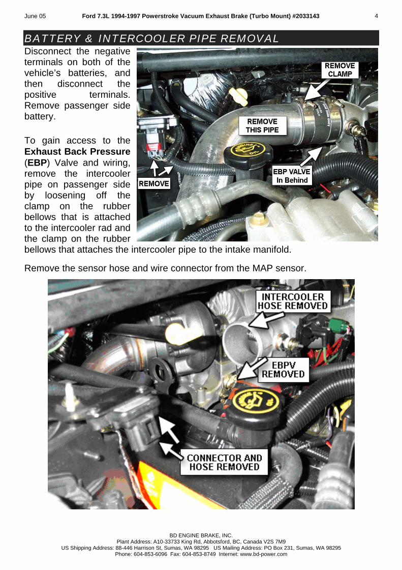
BATTERY & INTERCOOLER PIPE REMOVAL Disconnect the negative terminals on both of the vehicle’s batteries, and then disconnect the positive terminals. Remove passenger side battery. To gain access to the Exhaust Back Pressure (EBP) Valve and wiring, remove the intercooler pipe on passenger side by loosening off the clamp on the rubber bellows that is attached to the intercooler rad and the clamp on the rubber bellows that attaches the intercooler pipe to the intake manifold. Remove the sensor hose and wire connector from the MAP sensor.
BD ENGINE BRAKE, INC. Plant Address: A10-33733 King Rd, Abbotsford, BC, Canada V2S 7M9
US Shipping Address: 88-446 Harrison St, Sumas, WA 98295 US Mailing Address: PO Box 231, Sumas, WA 98295 Phone: 604-853-6096 Fax: 604-853-8749 Internet: www.bd-power.com
June 05 Ford 7.3L 1994-1997 Powerstroke Vacuum Exhaust Brake (Turbo Mount) #2033143 5
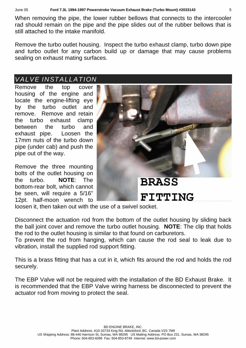
When removing the pipe, the lower rubber bellows that connects to the intercooler rad should remain on the pipe and the pipe slides out of the rubber bellows that is still attached to the intake manifold. Remove the turbo outlet housing. Inspect the turbo exhaust clamp, turbo down pipe and turbo outlet for any carbon build up or damage that may cause problems sealing on exhaust mating surfaces. VALVE INSTALLATION Remove the top cover housing of the engine and locate the engine-lifting eye by the turbo outlet and remove. Remove and retain the turbo exhaust clamp between the turbo and exhaust pipe. Loosen the 17mm nuts of the turbo down pipe (under cab) and push the pipe out of the way. Remove the three mounting bolts of the outlet housing on the turbo. NOTE: The bottom-rear bolt, which cannot be seen, will require a 5/16” 12pt. half-moon wrench to loosen it, then taken out with the use of a swivel socket. Disconnect the actuation rod from the bottom of the outlet housing by sliding back the ball joint cover and remove the turbo outlet housing. NOTE: The clip that holds the rod to the outlet housing is similar to that found on carburetors. To prevent the rod from hanging, which can cause the rod seal to leak due to vibration, install the supplied rod support fitting. This is a brass fitting that has a cut in it, which fits around the rod and holds the rod securely. The EBP Valve will not be required with the installation of the BD Exhaust Brake. It is recommended that the EBP Valve wiring harness be disconnected to prevent the actuator rod from moving to protect the seal.
BD ENGINE BRAKE, INC. Plant Address: A10-33733 King Rd, Abbotsford, BC, Canada V2S 7M9
US Shipping Address: 88-446 Harrison St, Sumas, WA 98295 US Mailing Address: PO Box 231, Sumas, WA 98295 Phone: 604-853-6096 Fax: 604-853-8749 Internet: www.bd-power.com
June 05 Ford 7.3L 1994-1997 Powerstroke Vacuum Exhaust Brake (Turbo Mount) #2033143 6
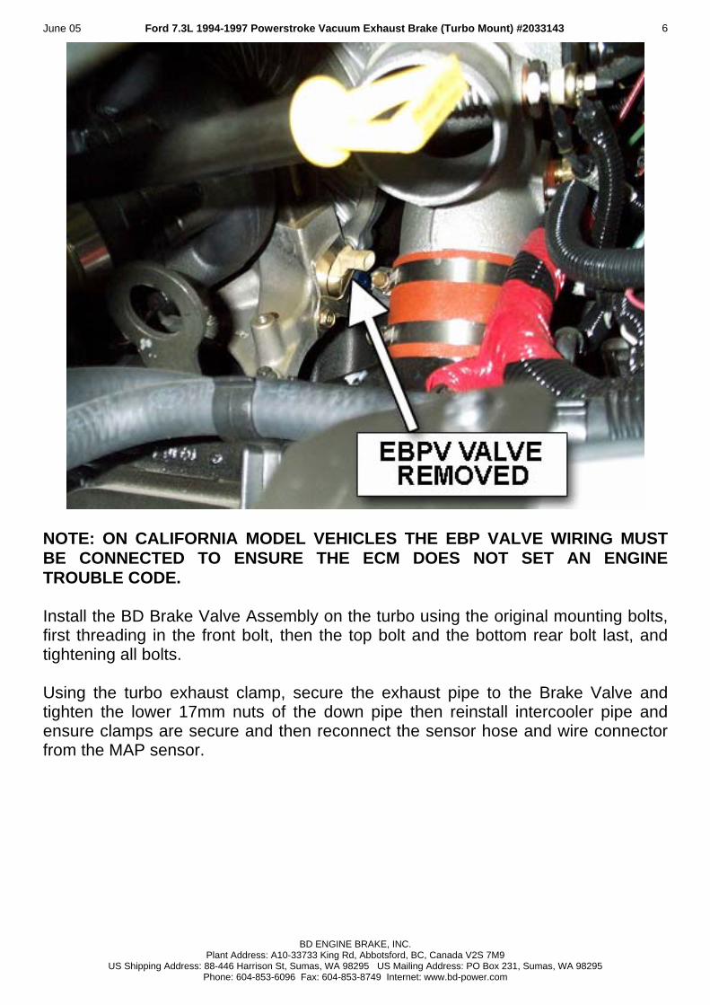
NOTE: ON CALIFORNIA MODEL VEHICLES THE EBP VALVE WIRING MUST BE CONNECTED TO ENSURE THE ECM DOES NOT SET AN ENGINE TROUBLE CODE. Install the BD Brake Valve Assembly on the turbo using the original mounting bolts, first threading in the front bolt, then the top bolt and the bottom rear bolt last, and tightening all bolts. Using the turbo exhaust clamp, secure the exhaust pipe to the Brake Valve and tighten the lower 17mm nuts of the down pipe then reinstall intercooler pipe and ensure clamps are secure and then reconnect the sensor hose and wire connector from the MAP sensor.
BD ENGINE BRAKE, INC. Plant Address: A10-33733 King Rd, Abbotsford, BC, Canada V2S 7M9
US Shipping Address: 88-446 Harrison St, Sumas, WA 98295 US Mailing Address: PO Box 231, Sumas, WA 98295 Phone: 604-853-6096 Fax: 604-853-8749 Internet: www.bd-power.com
June 05 Ford 7.3L 1994-1997 Powerstroke Vacuum Exhaust Brake (Turbo Mount) #2033143 7
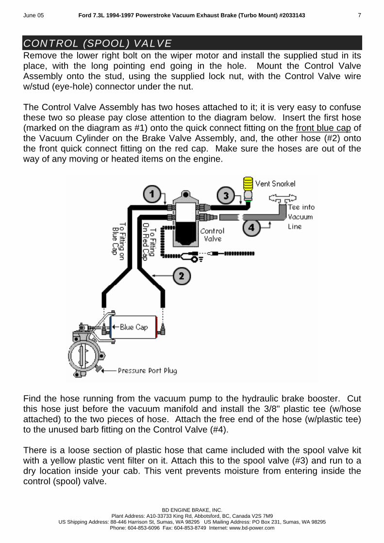
CONTROL (SPOOL) VALVE Remove the lower right bolt on the wiper motor and install the supplied stud in its place, with the long pointing end going in the hole. Mount the Control Valve Assembly onto the stud, using the supplied lock nut, with the Control Valve wire w/stud (eye-hole) connector under the nut. The Control Valve Assembly has two hoses attached to it; it is very easy to confuse these two so please pay close attention to the diagram below. Insert the first hose (marked on the diagram as #1) onto the quick connect fitting on the front blue cap of the Vacuum Cylinder on the Brake Valve Assembly, and, the other hose (#2) onto the front quick connect fitting on the red cap. Make sure the hoses are out of the way of any moving or heated items on the engine.
Find the hose running from the vacuum pump to the hydraulic brake booster. Cut this hose just before the vacuum manifold and install the 3/8" plastic tee (w/hose attached) to the two pieces of hose. Attach the free end of the hose (w/plastic tee) to the unused barb fitting on the Control Valve (#4). There is a loose section of plastic hose that came included with the spool valve kit with a yellow plastic vent filter on it. Attach this to the spool valve (#3) and run to a dry location inside your cab. This vent prevents moisture from entering inside the control (spool) valve.
BD ENGINE BRAKE, INC. Plant Address: A10-33733 King Rd, Abbotsford, BC, Canada V2S 7M9
US Shipping Address: 88-446 Harrison St, Sumas, WA 98295 US Mailing Address: PO Box 231, Sumas, WA 98295 Phone: 604-853-6096 Fax: 604-853-8749 Internet: www.bd-power.com
June 05 Ford 7.3L 1994-1997 Powerstroke Vacuum Exhaust Brake (Turbo Mount) #2033143 8
WIRING HARNESS
To Spool Valve
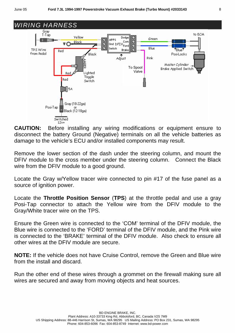
CAUTION: Before installing any wiring modifications or equipment ensure to disconnect the battery Ground (Negative) terminals on all the vehicle batteries as damage to the vehicle’s ECU and/or installed components may result. Remove the lower section of the dash under the steering column, and mount the DFIV module to the cross member under the steering column. Connect the Black wire from the DFIV module to a good ground. Locate the Gray w/Yellow tracer wire connected to pin #17 of the fuse panel as a source of ignition power. Locate the Throttle Position Sensor (TPS) at the throttle pedal and use a gray Posi-Tap connector to attach the Yellow wire from the DFIV module to the Gray/White tracer wire on the TPS. Ensure the Green wire is connected to the ‘COM’ terminal of the DFIV module, the Blue wire is connected to the ‘FORD’ terminal of the DFIV module, and the Pink wire is connected to the ‘BRAKE’ terminal of the DFIV module. Also check to ensure all other wires at the DFIV module are secure. NOTE: If the vehicle does not have Cruise Control, remove the Green and Blue wire from the install and discard. Run the other end of these wires through a grommet on the firewall making sure all wires are secured and away from moving objects and heat sources.
BD ENGINE BRAKE, INC. Plant Address: A10-33733 King Rd, Abbotsford, BC, Canada V2S 7M9
US Shipping Address: 88-446 Harrison St, Sumas, WA 98295 US Mailing Address: PO Box 231, Sumas, WA 98295 Phone: 604-853-6096 Fax: 604-853-8749 Internet: www.bd-power.com
June 05 Ford 7.3L 1994-1997 Powerstroke Vacuum Exhaust Brake (Turbo Mount) #2033143 9
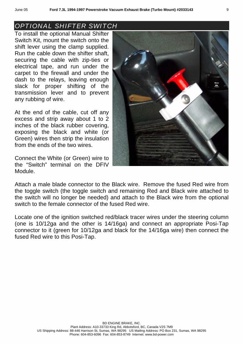
OPTIONAL SHIFTER SWITCH To install the optional Manual Shifter Switch Kit, mount the switch onto the shift lever using the clamp supplied. Run the cable down the shifter shaft, securing the cable with zip-ties or electrical tape, and run under the carpet to the firewall and under the dash to the relays, leaving enough slack for proper shifting of the transmission lever and to prevent any rubbing of wire. At the end of the cable, cut off any excess and strip away about 1 to 2 inches of the black rubber covering, exposing the black and white (or Green) wires then strip the insulation from the ends of the two wires. Connect the White (or Green) wire to the “Switch” terminal on the DFIV Module. Attach a male blade connector to the Black wire. Remove the fused Red wire from the toggle switch (the toggle switch and remaining Red and Black wire attached to the switch will no longer be needed) and attach to the Black wire from the optional switch to the female connector of the fused Red wire. Locate one of the ignition switched red/black tracer wires under the steering column (one is 10/12ga and the other is 14/16ga) and connect an appropriate Posi-Tap connector to it (green for 10/12ga and black for the 14/16ga wire) then connect the fused Red wire to this Posi-Tap.
BD ENGINE BRAKE, INC. Plant Address: A10-33733 King Rd, Abbotsford, BC, Canada V2S 7M9
US Shipping Address: 88-446 Harrison St, Sumas, WA 98295 US Mailing Address: PO Box 231, Sumas, WA 98295 Phone: 604-853-6096 Fax: 604-853-8749 Internet: www.bd-power.com
June 05 Ford 7.3L 1994-1997 Powerstroke Vacuum Exhaust Brake (Turbo Mount) #2033143 10
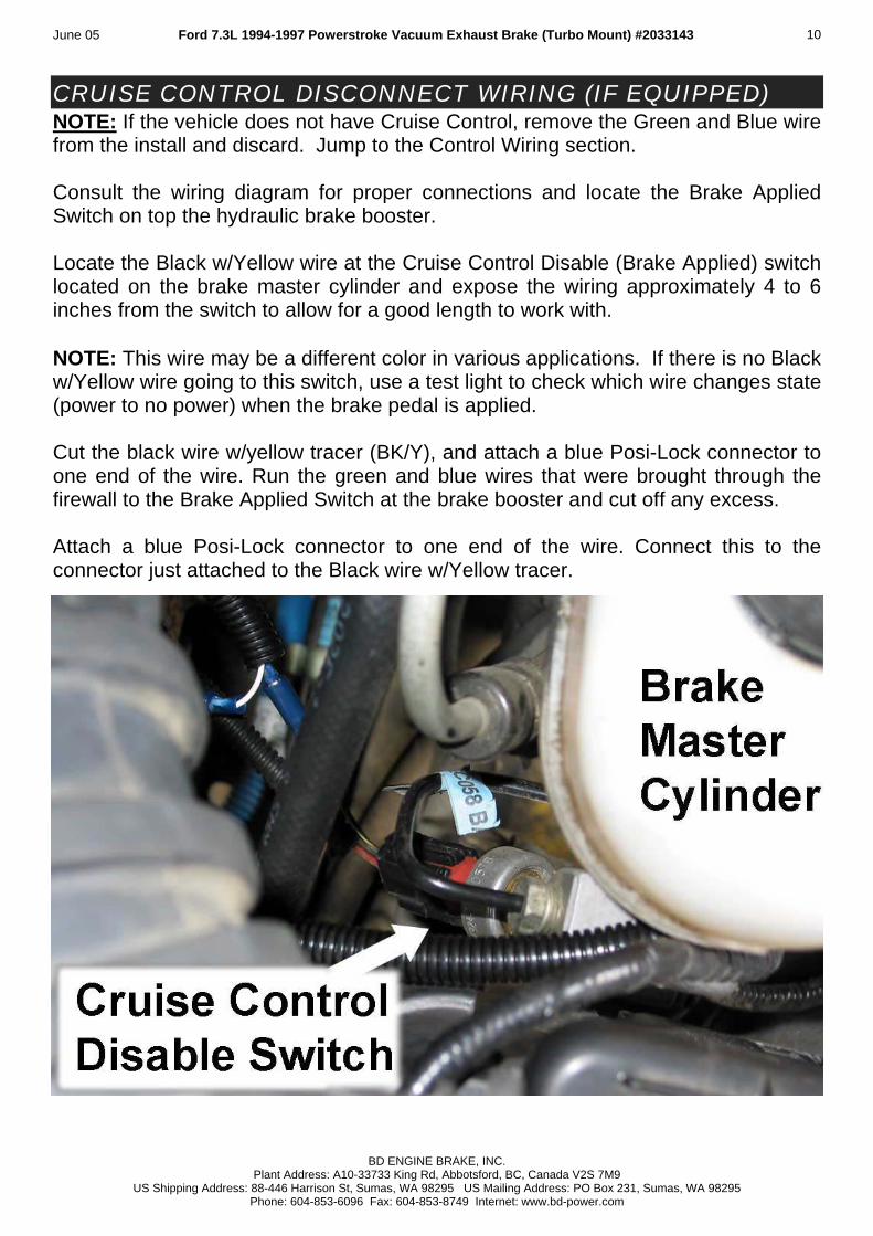
CRUISE CONTROL DISCONNECT WIRING (IF EQUIPPED) NOTE: If the vehicle does not have Cruise Control, remove the Green and Blue wire from the install and discard. Jump to the Control Wiring section. Consult the wiring diagram for proper connections and locate the Brake Applied Switch on top the hydraulic brake booster. Locate the Black w/Yellow wire at the Cruise Control Disable (Brake Applied) switch located on the brake master cylinder and expose the wiring approximately 4 to 6 inches from the switch to allow for a good length to work with. NOTE: This wire may be a different color in various applications. If there is no Black w/Yellow wire going to this switch, use a test light to check which wire changes state (power to no power) when the brake pedal is applied. Cut the black wire w/yellow tracer (BK/Y), and attach a blue Posi-Lock connector to one end of the wire. Run the green and blue wires that were brought through the firewall to the Brake Applied Switch at the brake booster and cut off any excess. Attach a blue Posi-Lock connector to one end of the wire. Connect this to the connector just attached to the Black wire w/Yellow tracer.
BD ENGINE BRAKE, INC. Plant Address: A10-33733 King Rd, Abbotsford, BC, Canada V2S 7M9
US Shipping Address: 88-446 Harrison St, Sumas, WA 98295 US Mailing Address: PO Box 231, Sumas, WA 98295 Phone: 604-853-6096 Fax: 604-853-8749 Internet: www.bd-power.com
June 05 Ford 7.3L 1994-1997 Powerstroke Vacuum Exhaust Brake (Turbo Mount) #2033143 11
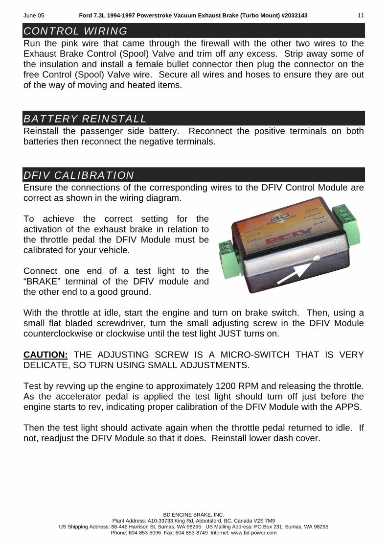
CONTROL WIRING Run the pink wire that came through the firewall with the other two wires to the Exhaust Brake Control (Spool) Valve and trim off any excess. Strip away some of the insulation and install a female bullet connector then plug the connector on the free Control (Spool) Valve wire. Secure all wires and hoses to ensure they are out of the way of moving and heated items. BATTERY REINSTALL Reinstall the passenger side battery. Reconnect the positive terminals on both batteries then reconnect the negative terminals. DFIV CALIBRATION Ensure the connections of the corresponding wires to the DFIV Control Module are correct as shown in the wiring diagram. To achieve the correct setting for the activation of the exhaust brake in relation to the throttle pedal the DFIV Module must be calibrated for your vehicle. Connect one end of a test light to the “BRAKE” terminal of the DFIV module and the other end to a good ground. With the throttle at idle, start the engine and turn on brake switch. Then, using a small flat bladed screwdriver, turn the small adjusting screw in the DFIV Module counterclockwise or clockwise until the test light JUST turns on. CAUTION: THE ADJUSTING SCREW IS A MICRO-SWITCH THAT IS VERY DELICATE, SO TURN USING SMALL ADJUSTMENTS. Test by revving up the engine to approximately 1200 RPM and releasing the throttle. As the accelerator pedal is applied the test light should turn off just before the engine starts to rev, indicating proper calibration of the DFIV Module with the APPS. Then the test light should activate again when the throttle pedal returned to idle. If not, readjust the DFIV Module so that it does. Reinstall lower dash cover.
BD ENGINE BRAKE, INC. Plant Address: A10-33733 King Rd, Abbotsford, BC, Canada V2S 7M9
US Shipping Address: 88-446 Harrison St, Sumas, WA 98295 US Mailing Address: PO Box 231, Sumas, WA 98295 Phone: 604-853-6096 Fax: 604-853-8749 Internet: www.bd-power.com
June 05 Ford 7.3L 1994-1997 Powerstroke Vacuum Exhaust Brake (Turbo Mount) #2033143 12
TESTING Start the engine and turn the Exhaust Brake on. Press down on the Accelerator Pedal to rev-up the engine to approximately 1200 R.P.M. and let go. The brake should have disengaged then activated again when the engine returns to idle. While driving, turn Cruise Control on, then try to activate brake, which the activation of brake should disconnect cruise. Turn brake off and activate cruise again, this time pressing down on the hydraulic brake pedal to check for cruise disconnects during that operation. The brake will need to be adjusted for the vehicle. If more holdback performance is required with the vehicle loaded, adjust the rod on the Vacuum Cylinder to close off the valve tighter. (NOTE: Only slight adjustments are required to gain desired effect, and, all adjustments should be done with vehicle turned off.) It is required that a standard pressure gauge be used to make the necessary adjustments to the brake valve. Adjust the brake to reach approximately 10-12 lb. while the engine is at idle. NOTE: Over the two weeks, the back pressure at idle may rise due to initial carbon build up, which the brake valve will need to be adjusted again. Check for any exhaust leaks and recheck all connections and hoses for security and interference from moving or heated items. After about 100 miles (160 km), re-torque the turbo exhaust clamp and flange bolts. MAINTENANCE & TROUBLE SHOOTING To extend life of the valve assembly, do not operate your vehicle for extended periods of time without activating the brake. On a twice-yearly interval, check and adjust the brake pressure to 10-12lbs. while the engine is at idle. The hoses, wires, fittings and clamps should be inspected on a regular basis for any deterioration, damage or leaks. If the brake ceases to work, then push in the black button on the top of the control (spool) valve while the engine is running. If the brake engages, then check that there is power at the fuse, all electrical connectors are firmly connected, all grounds are good, and that there is power output at the yellow wire coming through the fire wall, connecting to the control assembly, when the throttle pedal is at rest. If the brake failed to engage with black button pressed in while the engine is running, check for vacuum pump operation and check for leaks. Check for smooth operation when manually pulling and pushing of the lever on the brake valve (with the engine turned off). The control (spool) valve may have to be taken apart and cleaned.
BD ENGINE BRAKE, INC. Plant Address: A10-33733 King Rd, Abbotsford, BC, Canada V2S 7M9
US Shipping Address: 88-446 Harrison St, Sumas, WA 98295 US Mailing Address: PO Box 231, Sumas, WA 98295 Phone: 604-853-6096 Fax: 604-853-8749 Internet: www.bd-power.com
June 05 Ford 7.3L 1994-1997 Powerstroke Vacuum Exhaust Brake (Turbo Mount) #2033143 13
Following the diagrams in this manual, tracing hoses and wiring, checking continuity through electric components, or checking for any lines that are disconnected, should solve any problems that may arise. MEASURING IDLE BRAKE PRESSURE As mentioned in the installation instructions for this BD Exhaust Brake, the brake pressure has to be measured and adjusted when the vehicle is at idle. In the instructions, the brass plug on the brake valve had to be removed to take this measurement with a typical pressure gauge. For easier hook up of the gauge, the pressure can be measured by removing the Ford back pressure switch located behind the belt idler pulley on the front of the engine and plumb the gauge onto the pressure tube. SPOOL VALVE MAINTENANCE
Disassembly • Remove the two coil screws.
• Remove the two rear plate screws.
• Pop out the white and black bumpers, springs, and O-rings.
• Remove the spool and sleeve assembly from the valve body with a plastic or
wooden rod approximately the same size as the outside diameter of the sleeve.
Cleaning • Clean the spool and sleeve with some WD40 and compressed air.
• Inspect the spool and sleeve for any damage and inspect O-rings.
• The spool should move freely within the sleeve.
BD ENGINE BRAKE, INC. Plant Address: A10-33733 King Rd, Abbotsford, BC, Canada V2S 7M9
US Shipping Address: 88-446 Harrison St, Sumas, WA 98295 US Mailing Address: PO Box 231, Sumas, WA 98295 Phone: 604-853-6096 Fax: 604-853-8749 Internet: www.bd-power.com
June 05 Ford 7.3L 1994-1997 Powerstroke Vacuum Exhaust Brake (Turbo Mount) #2033143 14
Re-assembly • Reinstall the rear plate, O-ring, and black bumper onto the body.
• Gently slide the sleeve into the body cavity by pushing and turning at the
same time.
• Drop the spring into the sleeve.
• Gently insert the spool into the sleeve with a slow, turning action. • NOTE: The residual WD40 should be enough lubricant for assembly.
• Check to ensure that there is very little resistance felt when it’s inserted.
NOTE: If any resistance or binding is noted, remove the spool and try again.
• Once the spool is inserted and moving freely, reattach the coil, white bumper, and O-ring.
Testing • After reassembly is completed, push and release the manual override button.
The spool should move and return freely.
• If you have an air compressor, blow low-pressure (20-30 psi) air into Port #1, then push the override button. There should be a transfer of flow from Port #2 to Port #4.
• Re-install the valve on the engine, hook up the disconnected vacuum lines
and wiring, then check for correct operation of Brake, PressureLoc, etc.
Helpful Hints • Make sure all parts are spread out on a clean, lint-free surface while servicing
valve.
• **CAUTION** Do NOT use heavy grease or oils on the spool, sleeve, or O-rings. (Oil based lubricants will swell and distort rubber O-rings).
• Do not use any abrasive compounds on the spool or the sleeve.
BD ENGINE BRAKE, INC. Plant Address: A10-33733 King Rd, Abbotsford, BC, Canada V2S 7M9
US Shipping Address: 88-446 Harrison St, Sumas, WA 98295 US Mailing Address: PO Box 231, Sumas, WA 98295 Phone: 604-853-6096 Fax: 604-853-8749 Internet: www.bd-power.com
June 05 Ford 7.3L 1994-1997 Powerstroke Vacuum Exhaust Brake (Turbo Mount) #2033143 15
• Make sure all of the O-rings are re-installed and are in good condition by checking for nicks, scoring, or other damage.
OPERATING GUIDELINES Thank you for taking interest in the BD Engine Exhaust Brake. As a driver, you probably already know the need for extra braking power that your vehicle requires on the hills and long grades. With loads being towed behind you, the extra push when slowing down or maintaining speed on downward grades can prove to be a great strain on your vehicles hydraulic braking system, even to a point of “burn-up”. These guidelines were designed to offer you a better understanding of the benefits of exhaust brakes and are partly based upon material developed by the U.S. Department of Transportation National Highway Traffic Safety Administration. The emphasis on today’s vehicles is to give the consumer a product that can give them usable power with fuel efficiency. But, in the transition, the vehicles have lost their natural braking power, making it more easy for the vehicle to continue to roll and harder to stop. Of course, this gets more noticeable with the increase of weight, on or behind the vehicle. This is where an exhaust brake becomes a useful tool in increasing the driveline drag of the vehicle without the use of the hydraulic brakes; A tool that with maximum use or even occasional use, can reduce wear on hydraulic braking parts and at the same time increase safety. The BD Exhaust Brake can be used to help maintain a controlled vehicle speed on a downward grade, as well as slowing the vehicle down for such times as turns or exit ramps, without using your hydraulic brakes. But, the exhaust brake cannot be used as a parking brake or will not bring your vehicle to a complete stop. When you ride your hydraulic brakes, make hard stops or have poorly adjusted brakes, it creates high temperatures and as your brakes get hotter, there is more chance for brake fading and/or complete failure. By using a BD Exhaust Brake, the life and effectiveness of your hydraulic brakes will increase. This is because of the decreased use of the hydraulic brakes in situations like hills, the wear factor is reduced and there is less opportunity for your hydraulic brakes to heat up which would reduce the efficiency. With terrain that is a series of up and down grades, the BD Exhaust Brake will aid in reducing exhaust valve warpage. Because of the power needed to pull your vehicle and load up a hill, this generates a lot of heat. When you have reached the crest of the hill and are now coasting down the other side, the heated valves are too quickly
BD ENGINE BRAKE, INC. Plant Address: A10-33733 King Rd, Abbotsford, BC, Canada V2S 7M9
US Shipping Address: 88-446 Harrison St, Sumas, WA 98295 US Mailing Address: PO Box 231, Sumas, WA 98295 Phone: 604-853-6096 Fax: 604-853-8749 Internet: www.bd-power.com
June 05 Ford 7.3L 1994-1997 Powerstroke Vacuum Exhaust Brake (Turbo Mount) #2033143 16
cooled. With the exhaust brake engaged, the heat loss to the valves will be reduced, which can prevent valve warpage. When the toggle switch is turned to the “On” position, the valve is activated every time the driver takes his foot off of the throttle pedal. When the driver puts pressure back on the throttle pedal, the relay is activated and the valve opens again. Exhaust brakes are designed to operate with the throttle at idle, not to be used in conjunction with cruise controls, and not designed to aid in gear shifting. Such cases could cause damage to engine and/or the exhaust brake. The vehicle may require shifting down to achieve the necessary retarding force. Automatic transmissions with lock-up clutches in the convertors can achieve the best retarding force with the use of a clutch control device (i.e. AutoLoc). During cold weather engine start up, turn the brake on at idle while warming up the vehicle. This brings up the engine to normal operating temperature in much less time. Incorporated with the BD Exhaust Brake, there is a pressure regulating system that will control the created backpressure. If the backpressure reaches the set limit, the exhaust valve will open slightly to relieve the excess pressure. The brake pressure, at idle, is required to be checked and adjusted at time of installed, two weeks after installed, and on a regular twice a year interval. Use a standard pressure gauge and the pressure port on the exhaust valve, the brake pressure at idle must be set between 10 and 12lbs. The best scenario for exhaust braking is when going down hill, select a gear that lets you maintain a constant speed with little or no use of the hydraulic brakes, or, the same gear that would be used to go up the same grade of hill. This also depends on the weight, load or road conditions that the vehicle will come upon. So, in summary, by using the BD Exhaust Brake, you reduce the need for use of your hydraulic brakes in situations where you need to slow down or maintain (i.e. hills, off ramps, corners, approaching speed changes or traffic lights). By reducing the use of your hydraulic brakes in these situations, this will reduce the heat build up as well as wear and damage to linings and drums. When you reduce these factors you save your hydraulic brakes for when you really need them (i.e. for stopping or emergencies). The BD Exhaust Brake is not a substitute for your hydraulic brakes and, cannot correct or compensate for poorly maintained or misadjusted brakes. But, when you need to slow down or maintain a constant speed, the BD Exhaust Brake will be a valuable and effective tool. Exhaust Brakes are more efficient at preventing than correcting an over-speed condition.
BD ENGINE BRAKE, INC. Plant Address: A10-33733 King Rd, Abbotsford, BC, Canada V2S 7M9
US Shipping Address: 88-446 Harrison St, Sumas, WA 98295 US Mailing Address: PO Box 231, Sumas, WA 98295 Phone: 604-853-6096 Fax: 604-853-8749 Internet: www.bd-power.com
June 05 Ford 7.3L 1994-1997 Powerstroke Vacuum Exhaust Brake (Turbo Mount) #2033143 17
To increase the life of your exhaust brake we recommend daily operation. This could simply be switching it on and off a couple times a day. This will prevent the butterfly from sticking due to carboning up. Thank you and happy motoring. QUESTIONS? Thank you for purchasing the BD Exhaust Brake, please check out our web site at www.bd-power.com for other products such as BD PressureLoc, BD TowLoc or for info on our Performance Transmissions and components please call, fax or E-mail our BD Technical Service or Sales Department, 8:30am to 4:30pm Pacific Time, Monday to Friday.
BD ENGINE BRAKE, INC. Plant Address: A10-33733 King Rd, Abbotsford, BC, Canada V2S 7M9
US Shipping Address: 88-446 Harrison St, Sumas, WA 98295 US Mailing Address: PO Box 231, Sumas, WA 98295 Phone: 604-853-6096 Fax: 604-853-8749 Internet: www.bd-power.com
June 05 Ford 7.3L 1994-1997 Powerstroke Vacuum Exhaust Brake (Turbo Mount) #2033143 18
BD Engine Brake, Inc.
WARRANTY STATEMENT
THE INSTALLATION OF THIS PRODUCT INDICATES THAT THE BUYER HAS READ AND UNDERSTANDS THIS AGREEMENT AND ACCEPTS ITS TERMS AND CONDITIONS.
DISCLAIMER OF LIABILITY
BD Engine Brake Inc., its successors, distributors, jobbers, and dealers (hereafter “BD”) shall in no way be responsible for the product's proper use and service. THE BUYER HEREBY WAIVES ALL LIABILITY CLAIMS. BD disclaims any warranty and expressly disclaims any liability for personal injury or damages. BD also disclaims any liability for incidental or consequential damages including, but not limited to, repair labor, rental vehicles, hotel costs, or any other inconvenience costs by reason of use or sale of any such equipment. The BUYER acknowledges and agrees that the disclaimer of any liability for personal injury is a material term for this agreement and the BUYER agrees to indemnify BD and to hold BD harmless from any claim related to the item of any equipment purchased. This warranty shall not apply to any unit that has been improperly stored or installed, or to misapplication, improper operation conditions, accidents, neglect, or which has been improperly repaired or altered or otherwise mistreated by the BUYER or his agent. BD also assumes no liability regarding the improper installation or misapplication of its products. It is the installer's responsibility to check for proper installation and if in doubt, contact the manufacturer.
LIMITATION OF WARRANTY BD Engine Brake Inc. (hereafter "BD") warrants to the BUYER that any parts purchased shall be free from defects in material workmanship. A defect is defined as a condition within the product that would render the product inoperable. BD gives Limited Warranty as to description, quality, merchantability, fitness for any product’s purpose, productiveness, or any other matter of BD's product sold herewith. BD shall be in no way responsible for the product’s open use and service and the BUYER hereby waives all rights other than those expressly written herein. This Warranty shall not be extended or varied except by a written instrument signed by BD and the BUYER. The Warranty is Limited to two (2) years from the date of sale. Labor costs incurred by the removal and replacement of the BD product, while performing warranty work, will be covered for 1 (one) year, payable at BD rates, at authorized centers and with prior approval. Until BD has approved the claim, the consumer may be responsible for these costs. A Return Authorization (WA) number, obtained in advance from BD, must accompany all products returned for warranty consideration. All products must be returned, shipping prepaid, to BD and must be accompanied by a dated proof of purchase receipt. All Warranty claims are subject to approval by BD and repaired or replaced product will be returned to the customer freight collect. Accepted warranty units, which have been replaced, become the sole property of BD. This warranty is in lieu of all other warranties or guaranties, either expressed or implied, and shall not extend to any consumer or to any person other than the original purchaser residing within the boundaries of the continental U.S. or Canada. IN THE EVENT THAT THE BUYER DOES NOT AGREE WITH THIS AGREEMENT, THE BUYER MAY PROMPTLY RETURN THIS PRODUCT, IN A NEW AND UNUSED CONDITION, WITH A DATED PROOF OF PURCHASE, TO THE PLACE OF PURCHASE WITHIN THIRTY (30) DAYS FROM DATE OF PURCHASE FOR A FULL REFUND.
BD ENGINE BRAKE, INC. Plant Address: A10-33733 King Rd, Abbotsford, BC, Canada V2S 7M9
US Shipping Address: 88-446 Harrison St, Sumas, WA 98295 US Mailing Address: PO Box 231, Sumas, WA 98295 Phone: 604-853-6096 Fax: 604-853-8749 Internet: www.bd-power.com