1992-8645 ON THE ANALYSIS OF PARAMETERS’ … · Image Inpainting is an important task in the...
10
Journal of Theoretical and Applied Information Technology 31 st January 2013. Vol. 47 No.3 © 2005 - 2013 JATIT & LLS. All rights reserved . ISSN: 1992-8645 www.jatit.org E-ISSN: 1817-3195 926 ON THE ANALYSIS OF PARAMETERS’ EFFECT IN PDE- BASED IMAGE INPAINTING 1 BAHA. FERGANI, 2 MOHAMED KHIREDDINE. KHOLLADI 1 Asstt Prof. MISC Laboratory, Mentouri University of Constantine, Algeria. 2 Professor. MISC Laboratory, Mentouri University of Constantine, Algeria. E-mail: 1 [email protected], 2 [email protected] ABSTRACT Image Inpainting is an important task in the field of image processing, with many applications in the fields of image and vision analysis. It aims at restoring damaged or missed regions in images in the case of undetectable forms. The basic idea in image inpainting, according to the Bertalmio’s approach, is to smoothly propagate information from the boundaries of the missed region toward the inside of the gap in the direction of isophotes. The purpose of this paper is to analyze the effects of different parameters in Bertalmio’s approach on the quality of the resulting inpainted image. The parameters dealt with in the paper are the rate of improvement, the number of iterations, the number of isotropic diffusion and the number of anisotropic diffusion. Keywords: Image, Damaged image, Inpainting, Partial Differential Equation (PDE). 1. INTRODUCTION Digitization techniques help in producing digital copies of any patrimonial document (images, text, etc.) to provide wider use of its rich resources while preserving rare valuable and fragile documents. The quality of these digital copies depends greatly on the quality of the original documents, which are often affected by several types of degradation limiting their use. Stanco et al. [1, 2] classify the defects of documents into three sets, depending on their origin; 1. Mechanical damage: it contains defects that are originated by an inaccurate handling of documents such as cracks, scratches, added text (Figure 1), gaps (see Figure 2), etc. 2. Chemical damage: defects of this often are generally caused by water, humidity (semi transparent blotches) or chemical reactions between the document and some microorganisms (Figure 3). 3. Deposited matters: extraneous matter may adhere to the surfaces creating small spots that cover the original image (Figure 4). With classical restoration, called also physical restoration, clear images can be produced; but only in an extremely expensive way, and often the damage still remains visible. Commercial software for image inpainting exists. They propose heavy user-guided restoration procedures, where the defects are not automatically traced. Also, all the corrections to be done have to be user suggested. Virtual restoration becomes complex and expensive, and it can be performed only by skilled people. Automated restoration called digital inpainting is, hence, required to obtain fast, less expensive, simple and effective results. Figure 1: Mechanical Damage: Added Text. Figure 2: Mechanical Damage: Gaps.
Transcript of 1992-8645 ON THE ANALYSIS OF PARAMETERS’ … · Image Inpainting is an important task in the...

Journal of Theoretical and Applied Information Technology 31st January 2013. Vol. 47 No.3
© 2005 - 2013 JATIT & LLS. All rights reserved.
ISSN: 1992-8645 www.jatit.org E-ISSN: 1817-3195
926
ON THE ANALYSIS OF PARAMETERS’ EFFECT IN PDE-BASED IMAGE INPAINTING
1BAHA. FERGANI, 2 MOHAMED KHIREDDINE. KHOLLADI
1Asstt Prof. MISC Laboratory, Mentouri University of Constantine, Algeria.
2Professor. MISC Laboratory, Mentouri University of Constantine, Algeria.
E-mail: [email protected], 2 [email protected]
ABSTRACT
Image Inpainting is an important task in the field of image processing, with many applications in the fields of image and vision analysis. It aims at restoring damaged or missed regions in images in the case of undetectable forms. The basic idea in image inpainting, according to the Bertalmio’s approach, is to smoothly propagate information from the boundaries of the missed region toward the inside of the gap in the direction of isophotes. The purpose of this paper is to analyze the effects of different parameters in Bertalmio’s approach on the quality of the resulting inpainted image. The parameters dealt with in the paper are the rate of improvement, the number of iterations, the number of isotropic diffusion and the number of anisotropic diffusion.
Keywords: Image, Damaged image, Inpainting, Partial Differential Equation (PDE). 1. INTRODUCTION
Digitization techniques help in producing digital copies of any patrimonial document (images, text, etc.) to provide wider use of its rich resources while preserving rare valuable and fragile documents. The quality of these digital copies depends greatly on the quality of the original documents, which are often affected by several types of degradation limiting their use. Stanco et al. [1, 2] classify the defects of documents into three sets, depending on their origin; 1. Mechanical damage: it contains defects that are originated by an inaccurate handling of documents such as cracks, scratches, added text (Figure 1), gaps (see Figure 2), etc. 2. Chemical damage: defects of this often are generally caused by water, humidity (semi transparent blotches) or chemical reactions between the document and some microorganisms (Figure 3). 3. Deposited matters: extraneous matter may adhere to the surfaces creating small spots that cover the original image (Figure 4). With classical restoration, called also physical restoration, clear images can be produced; but only in an extremely expensive way, and often the damage still remains visible.
Commercial software for image inpainting exists. They propose heavy user-guided restoration procedures, where the defects are not automatically traced. Also, all the corrections to be done have to be user suggested. Virtual restoration becomes complex and expensive, and it can be performed only by skilled people. Automated restoration
called digital inpainting is, hence, required to obtain fast, less expensive, simple and effective results.
Figure 1: Mechanical Damage: Added Text.
Figure 2: Mechanical Damage: Gaps.

Journal of Theoretical and Applied Information Technology 31st January 2013. Vol. 47 No.3
© 2005 - 2013 JATIT & LLS. All rights reserved.
ISSN: 1992-8645 www.jatit.org E-ISSN: 1817-3195
927
Figure 3: Chemical Damage: Paper Yellowing
Figure 4: Deposited Matters: Spots
Digital inpainting is defined as the art of rebuilding missing data. It consists of filling in unknown missing data (called damaged region or target region) in a known region (called source region) of an image in such a way that an observer would be unable to detect any changes applied on the image (Figure 5). Image inpainting is also used to fill in holes left by removing chosen objects (see Figure 6 and Figure 7).
Digital inpainting was first introduced by Bertalmio et al. in [3]. Having a manually selected inpainting region Ω in a damaged image I: Ф → R3 (or Ф → R) in case of grayscale image) and a mask M: Ω → {0, 1}. The inpainting algorithm fills in the region Ω where M (p) = 0 (p is a pixel belonging to Ф) [4]. The boundary ∂Ω representing the area between the two regions (Ω and the source region) plays a major role in deciding the intensities to be put in Ω. All the algorithms are iterative and try to fill in ∂Ω first and move inwards successively altering ∂Ω each time. The algorithm stops when all the pixels in Ω are successfully assigned some values.
a. Damaged Image.
b. Inpainted Image.
Figure 5: Inpainting Damaged Image in an Undetectable Way [8].
a. Stalin with Nikolai Yezhov
b. The inpainted image with Yezhov removed
Figure 6: Inpainting the Hole Left by Removing Yezhov[7]

Journal of Theoretical and Applied Information Technology 31st January 2013. Vol. 47 No.3
© 2005 - 2013 JATIT & LLS. All rights reserved.
ISSN: 1992-8645 www.jatit.org E-ISSN: 1817-3195
928
Figure 7: Inpainting The Hole Left by Removing The
Woman [6].
Many approaches of image inpainting have been proposed in literature. Generally, image inpainting methods can be classified into two main categories [5]: diffusion-based methods and exemplar based methods. 1. Diffusion based methods [4], also known as geometric methods, were first introduced by Bertalmio et al. in [3]. This class of methods tries to fill in the missing region of a damaged image through a diffusion process, using Partial Differential Equation (PDE), by propagating the information known on the boundary towards the interior side of the hole. The edges recovered with this approach are smooth and continuous at the boundary of the hole. However, the main drawback of this approach is that it cannot deal with texture and big missing data.
2. Exemplar based texture synthesis methods, first introduced by Criminissi et al. in [6], preserve linear structure by reordering the synthesizing process according to the priority of pixels, which is given by the product of a confidence term and data term. There is a delicate relation between the two terms. The data term tends to push isophotes rapidly inward, while the confidence term tends to suppress precisely this shortening of incursion into the missing region. After deciding priority, the exemplar based image inpainting algorithm uses patch based structure synthesis to replicate the texture in an image to fill in the gap and searchers the most similar texture by the sum of squared differences (SSD). The algorithm is capable of propagating both linear and two dimensional textures into the missing region.
The rest of the paper is organized as follows. In Section 2, Bertalmio’s inpainting algorithm is presented. Section 3 presents our experimental results of Bertalmio’s inpainting algorithm. A discussion of the effects of different parameter values (dt, T, B, A) are also presented in the same section. Finally, Section 4 concludes the paper.
2. BERTALMIO’S ALGORITHM 2.1. Fundamentals
This image inpainting algorithm fill the missing region Ω in an image by using Partial Differential Equation (PDE) to propagate information from surroundings of the missing region Ω along the isophotes direction, which is perpendicular to the gradient vector gap contour (see Figure 10). It must propagate information while preserving edges.
As reported by Bertalmio et al. in [3], an inpainting algorithm is guided by four observations:
a. The global picture determines how to fill in the gap, the purpose of inpainting is to restore the unity of the work. 2.
b. The structure of the area surrounding the missing area Ω is continued in the gap, contour lines are drawn via the prolongation of those arriving at the boundary of the missing region ∂Ω.
c. Different regions inside Ω, as defined by the contour lines, are filled with color, matching those of the boundary ∂Ω.
Small details are painted, in other words texture is added. For example, little white spots on an otherwise uniformly blue sky.
Figure 8: Propagation Direction as the normal to the
signed distance to the boundary of the region to be inpainted [8].
Figure 9: Unsuccessful Choice of the information propagation direction. Left: detail of the original image, region to be inpainted is in white. Right: Image Inpainted [8]
Journal of Theoretical and Applied Information Technology 31st January 2013. Vol. 47 No.3
© 2005 - 2013 JATIT & LLS. All rights reserved.
ISSN: 1992-8645 www.jatit.org E-ISSN: 1817-3195
929
Figure 10: Information Propagation In The Isophotes
Direction [9]
2.2. The Inpainting (Bertalmio’s) Algorithm Let I0 (i, j): [0, M] x [0, N] → R, with
[0, M] x [0, N] ϹN x N, be a discrete 2D gray level image. The inpainting procedure will construct a family of images I (i, j, n): [0, M] x [0, N] x [0, ∞) → R such that I (i, j, 0) = I0 (i, j) and lim n→∞ I (i, j, n) = IR (i, j), where IR (i, j) is the output of the algorithm (Inpainted image). Let Ω represent the region to be inpainted and ∂Ω be the boundary of the region to be inpainted.
The idea of Bertalmio’s inpainting algorithm is as follows. First, minimize the influence of noise on the estimation of the direction of the isophotes arriving at the boundary ∂Ω. For that, the whole original image undergoes anisotropic diffusion smoothing. Then, the image enters the inpainting loop where only the values inside the missing region Ω are modified using the following evolution equation:
In+1(i, j) = 𝐼𝑛(𝑖, 𝑗) + ∆𝑡 ∗ 𝐼𝑡𝑛(𝑖, 𝑗)
Where n denotes the inpainting time, ∆t is the rate of improvement and 𝐼𝑡𝑛(𝑖, 𝑗) is the update of the image In (i, j). As suggested by manual inpainting techniques, we need to smoothly propagate information from outside ∂Ω into Ω. Let Ln(i, j) being the information that we wish to propagate and N��⃗ n(i, j) is the propagation direction. Given the information and propagation direction, the value of the current pixel to be inpainted is: 𝐼𝑡𝑛(𝑖, 𝑗) = 𝛿𝐿�⃗ 𝑛(𝑖, 𝑗).𝑁��⃗ 𝑛(𝑖, 𝑗). 𝛿𝐿�⃗ 𝑛(𝑖, 𝑗) is a measure of the change in the information. 𝐿�⃗ 𝑛(𝑖, 𝑗) is laplacien image smoothness estimator, it can be written as:𝐿𝑛(𝑖, 𝑗) = 𝐼𝑥𝑥𝑛 (𝑖, 𝑗) + 𝐼𝑦𝑦𝑛 (𝑖, 𝑗). 𝑁��⃗ 𝑛(𝑖, 𝑗) =∇┴𝐼𝑛(𝑖, 𝑗) =[-𝐼𝑦 𝐼𝑥 ] is the smallest spatial change, it’s the 90° of the gradient (Gradient ∇𝐼𝑛(𝑖, 𝑗) gives us the largest spatial change).
The PDE -based image inpainting algorithm is summarized as follows:
Where
I: is the input image. M is the used mask. T is the number of iterations. Its value depends on the size of the missing region Ω. A is the number of isotropic diffusion steps. B is the number of anisotropic diffusion steps. dt is the rate of improvement. 3. RESULTS AND DISCUSSIONS
In this section, the implementation’s results of Bertalmio’s image inpainting algorithm are presented. All experiments were run on a 2.10GHZ Pentium (R) dual-core CPU with 2GB of RAM.
It’s interessting to demonstrate the effects of different values of parameters on the overal performance of the algorithm. In their algorithm, Bertamio et al. [3] use the following parameters: the rate of improvement dt, the number of iterations T, the number of isotropic diffusion A, the number of anisotropic diffusion B.
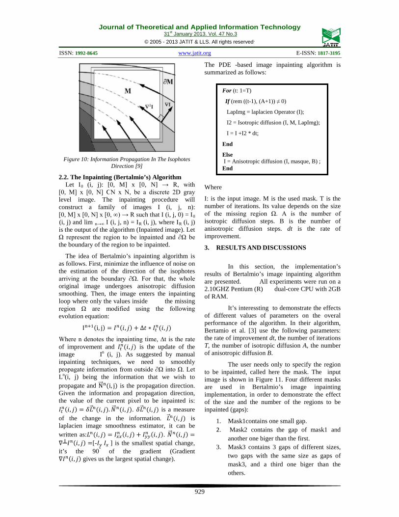
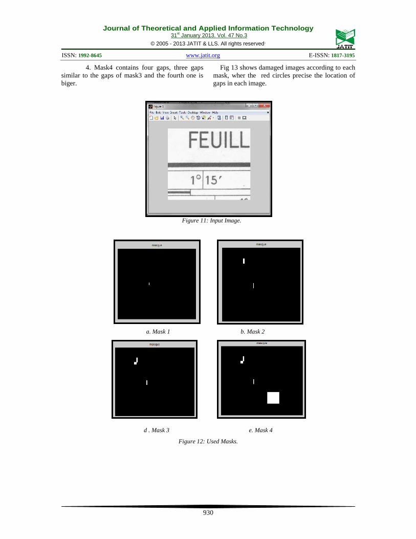
The user needs only to specify the region to be inpainted, called here the mask. The input image is shown in Figure 11. Four different masks are used in Bertalmio’s image inpainting implementation, in order to demonstrate the effect of the size and the number of the regions to be inpainted (gaps):
1. Mask1contains one small gap. 2. Mask2 contains the gap of mask1 and
another one biger than the first. 3. Mask3 contains 3 gaps of different sizes,
two gaps with the same size as gaps of mask3, and a third one biger than the others.
For (t: 1=T)
If (rem ((t-1), (A+1)) ≠ 0)
LapImg = laplacien Operator (I);
I2 = Isotropic diffusion (I, M, LapImg);
I = I +I2 * dt;
End
Else I = Anisotropic diffusion (I, masque, B) ; End
Journal of Theoretical and Applied Information Technology 31st January 2013. Vol. 47 No.3
© 2005 - 2013 JATIT & LLS. All rights reserved.
ISSN: 1992-8645 www.jatit.org E-ISSN: 1817-3195
930
4. Mask4 contains four gaps, three gaps similar to the gaps of mask3 and the fourth one is biger.
Fig 13 shows damaged images according to each mask, wher the red circles precise the location of gaps in each image.
Figure 11: Input Image.
a. Mask 1 b. Mask 2
d . Mask 3 e. Mask 4
Figure 12: Used Masks.

Journal of Theoretical and Applied Information Technology 31st January 2013. Vol. 47 No.3
© 2005 - 2013 JATIT & LLS. All rights reserved.
ISSN: 1992-8645 www.jatit.org E-ISSN: 1817-3195
931
a. Damaged Image Using Mask 1. b. Damaged Image Using Mask 2.
c. Damaged Image Using Mask 3. d. Damaged Image Using Mask 4.
Fig 13: Used Damaged Images.
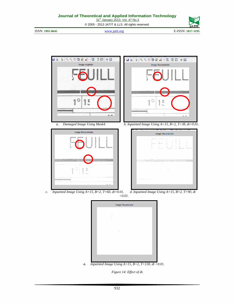
3.1. Effect of the Rate of improvement dt
In this part, we illustrate the effect of different values of the rate of improvement dt on the overall performance of the algorithm. We aim at answering the question: ‘is there a relationship between the rate of improvement dt and the number of iterations T?’ In other words, can the value of the number of iterations T correct the effect of a bad value of the rate of improvement dt (too low or too high). Fig 14 shows the effect of different values of dt on Bertalmio’s image
inpainting algorithm. Using the same value of dt =0.01 and changing T’s value. Figure 14.a shows the damaged image using mask4. Figure 14.b shows inpainted image using dt =0.01 and T=38.
From the result, it is clear that the quality of the inpainted image is bad; because of the value of dt (it is too high). Increasing the value of T to 60, 90 and 130; the quality of the inpainted image is worst in each case.
Hence, a bad value of dt can’t be corrected by increasing or decreasing the value of the number of iterations T. .
Journal of Theoretical and Applied Information Technology 31st January 2013. Vol. 47 No.3
© 2005 - 2013 JATIT & LLS. All rights reserved.
ISSN: 1992-8645 www.jatit.org E-ISSN: 1817-3195
932
a. Damaged Image Using Mask4. b. Inpainted Image Using A=15, B=2, T=38, dt=0.01.
c. Inpainted Image Using A=15, B=2, T=60, dt=0.01. d. Inpainted Image Using A=15, B=2, T=90, dt
=0.01.
e. Inpainted Image Using A=15, B=2, T=130, dt =0.01.
Figure 14: Effect of dt.
Journal of Theoretical and Applied Information Technology 31st January 2013. Vol. 47 No.3
© 2005 - 2013 JATIT & LLS. All rights reserved.
ISSN: 1992-8645 www.jatit.org E-ISSN: 1817-3195
933
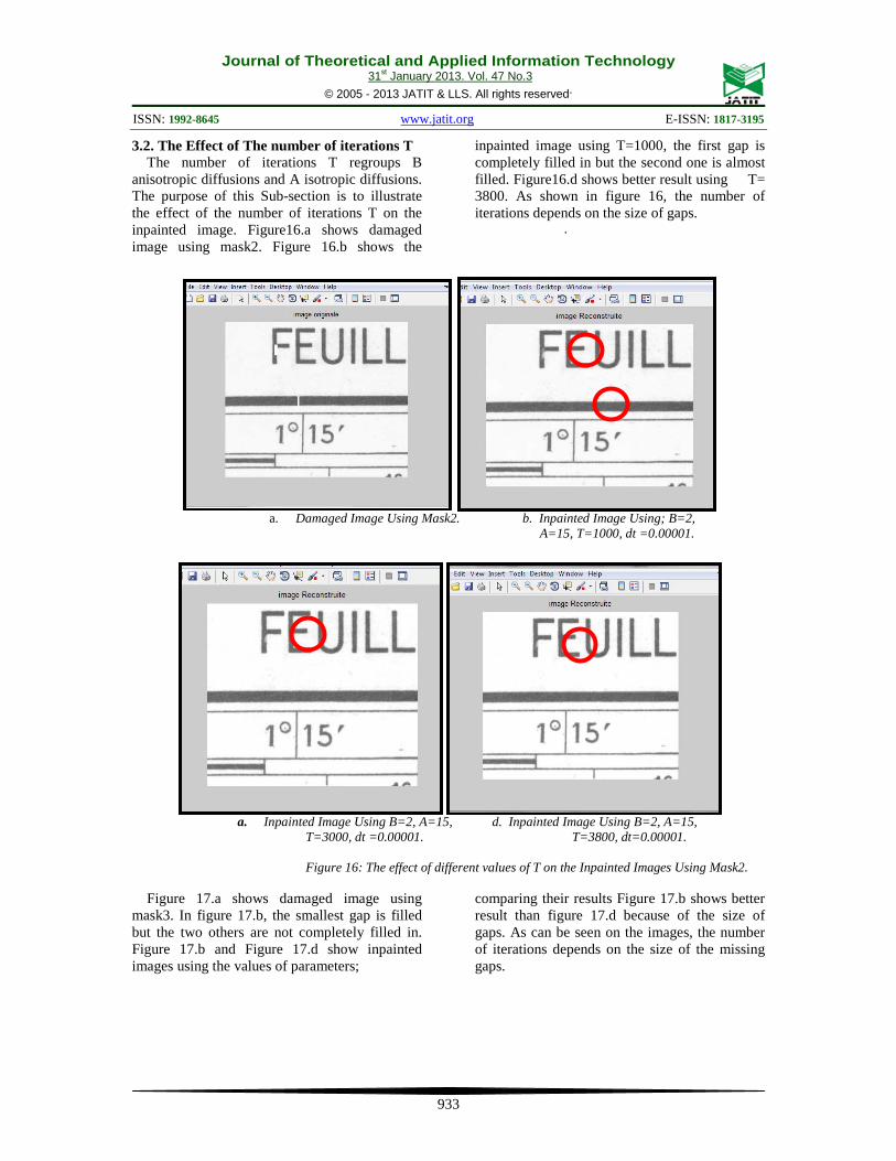
3.2. The Effect of The number of iterations T The number of iterations T regroups B
anisotropic diffusions and A isotropic diffusions. The purpose of this Sub-section is to illustrate the effect of the number of iterations T on the inpainted image. Figure16.a shows damaged image using mask2. Figure 16.b shows the
inpainted image using T=1000, the first gap is completely filled in but the second one is almost filled. Figure16.d shows better result using T= 3800. As shown in figure 16, the number of iterations depends on the size of gaps.
.
a. Damaged Image Using Mask2. b. Inpainted Image Using; B=2,
A=15, T=1000, dt =0.00001.
a. Inpainted Image Using B=2, A=15, d. Inpainted Image Using B=2, A=15,
T=3000, dt =0.00001. T=3800, dt=0.00001. Figure 16: The effect of different values of T on the Inpainted Images Using Mask2.
Figure 17.a shows damaged image using mask3. In figure 17.b, the smallest gap is filled but the two others are not completely filled in. Figure 17.b and Figure 17.d show inpainted images using the values of parameters;
comparing their results Figure 17.b shows better result than figure 17.d because of the size of gaps. As can be seen on the images, the number of iterations depends on the size of the missing gaps.

Journal of Theoretical and Applied Information Technology 31st January 2013. Vol. 47 No.3
© 2005 - 2013 JATIT & LLS. All rights reserved.
ISSN: 1992-8645 www.jatit.org E-ISSN: 1817-3195
934
a. Damaged Image Using Mask3. b. Inpainted Image Using B=2, A=15,
T=3800, dt =0.00001.
c. Damaged Image Using Mask4. d. Inpainted Image Using B=2, A=15,
T=3800; dt =0.00001.
Figure 17: The effect of T on Inpainted Images Using Mask 3 and Mask4.
3.3. The Effect of the Number of the Anisotropic Diffusion B
The aim of this subsection is to study the effect of the number of different values of the anisotropic diffusion B. Figure 17 shows the effect of changing
the value of B on the inpainting images. Figure 17.a shows the inpainted image using B=2, figure 17.b shows the inpainted image using B=5. The two inpainted images are similar
.
a. Inpainted Image Using; B=2, A=15, b. Inpainted Image Using; B=5, A=15,
T=600, dt =0.00001. T=600, dt =0.00001.
Figure 18: The Effect of B on Inpainted Images.

Journal of Theoretical and Applied Information Technology 31st January 2013. Vol. 47 No.3
© 2005 - 2013 JATIT & LLS. All rights reserved.
ISSN: 1992-8645 www.jatit.org E-ISSN: 1817-3195
935
4. CONCLUSION
This paper presented our implementation results of the image inpainting algorithm proposed by Bertalmio et al. A discussion of the effect of the algorithm’s parameters and the effect of the size of the damaged image area on the inpainted image are also presented. Four parameters are used in the inpainting algorithm: the rate of improvement dt, the number of iterations T, the number of isotropic iterations A and the number of anisotropic iterations B. As shown in the above section, the rate of improvement dt is an important parameter and a bad value of dt can’t be connected by related to the increasing or decreasing the value of T. Four different masks are used in our implementation to illustrate the effect of the size of the damaged area. As shown in the experimental and discussion section, only small gaps are completely filled in. Big damaged area and the number of iterations T depends on the size of gaps.
Since no previous analysis of these parameters is done in literature, we could not compare our results with others. So, as a future work, we intend to apply other approaches to solve the same problem in order to give more validation to the conducted study.
ACKNOWLEDGMENTS
The authors would like to thank Mr. Abdelbaki BOUGUESSA from Mentouri University for providing us with the maps we are using as input images.
REFERENCES [1] Stanco, F., Ramponi, G., and Tenze, L.
“Transparent Bloches in old photographic Prints”. 5th COST 276 Workshop, 2003, pp.1-5.
[2] Stanco, F., Ramponi, G., and de Polo, A. « Towards the Automated Restoration of old Photographic Prints: A Survey”. EUROCON 2003 Ljubljana, Slovenia.2003.
[3] Bertalmio, M.,Sapiro, G., Casselles, V. and Ballester, C . 2000. “Image inpainting”. Computer Graphics, SIGGRAPH 2000, pp.417-424.
[4] B Bugeau, A., and Bertalmio, M. ”Combining texture synthesis and diffusion for image inpainting”. VISAPP 2009- Proceedings of the fourth International conference on Computer Vision Theory and Applications, Portugal. 2009.
[5] Zhang, Q., and Lin, J. “Exemplar based inpainting using color distribution”. Journal of information science and engineering, volume 28, 2012, 641-654.
[6] Criminissi, A., Pérez, P., and Toyama, K.”Region filling and object removal by exemplar based images inpainting”. IEEE transactions on image processing, vol.13, 2004, pp.1200-1212.
[7] http://www.newseum.org/berlinwall/commissar _vanishes /vanishes.htm.
[8] Bertalmio, M. “Processing of flat and non-flat image information on arbitrary manifolds using partial differential equations”. Doctoral thesis, university of Minnesota, 2001.
[9] Drira, F. « Contribution à la restauration des images de documents anciens ». Doctoral Thesis, Order Number: 2007-ISAL-0111.INSA, Lyon.