1991: Catalyst Tube Failure investigation and Inspectïon ...
10
Catalyst Tube Failure investigation and Inspectïon FoIIowing Furnace Fire This paper describes the failure investigation and inspection following a primary, steam/hydrocarbon refarmer furnace fire. Catalysts tubes experienced stress-rupture, thermal shock, and internal carburization and melting. Follow-up inspection included an external eddy current technique. C.A. Baer Chevron Research and Technology Company, Richmond, CA 94804 S.P. Henson Chevron U.S.A, Inc., Pascagoula, MS. 39567 SUMMARY Initially a flow orifice gate valve, which was part of the instrumentation for a primary, steam/hydrocarbon reformer furnace failed by caustic stress corrosion cracking. This failure led to the loss of steam feed to one cell in the terrace-wall furnace. Hydrocarbon feed continued to flow, but, without the usual endothermic reaction, the Manaurite 36X catalyst tubes overheated. Some tubes failed by stress-rupture. Others failed by thermal shock when steam was suddenly reintroduced and the furnace shut down. The failure investigation also showed that some tubes were heavily carburized (and had melted) on the inside surface. The tubes which did not rupture were inspected for thermal shock cracks and creep fissures with an external eddy current technique. A magnetic measuring technique was used to inspect for internal carburization and melting. One tube was sacrificed as a Standard to confirm that nondestructive examination results were accurate. The steam feed control valve was redesigned to prevent complete shut-off of steam flow during future operation. BACKGROUND Fire Scenario In early 1989, a primary reformer furnace fire caused the unplanned shutdown of one of Chevron's hydrogen plants. The plant upset began when steam flow into one of the two furnace cells was lost for approximately 25 minutes. The burner fuel gas was reduced, but tube temperatures continued to rise. About 15 minutes after steam flow resumed, fuel gas was shut off completely. During this 40 minute excursion a number of catalyst tubes ruptured, and the escaping feed gas and hydrogen began to burn inside the furnace. Visual inspection after the fire revealed that a cluster of 14 catalyst tubes at one end of the affected cell had failed. Ten tubes were bulged and had longitudinal cracks (Figure 1). Pieces which had broken out of 4 other tubes (Figure 2) were lying on the furnace floor. The other tubes in the cell were examined according to standard Chevron practice (automatic ultrasonic inspection), but no additional tube damage was found. 26
Transcript of 1991: Catalyst Tube Failure investigation and Inspectïon ...
Catalyst Tube Failure investigation andInspectïon FoIIowing Furnace Fire
This paper describes the failure investigation and inspection following a primary,steam/hydrocarbon re farmer furnace fire. Catalysts tubes experienced stress-rupture,thermal shock, and internal carburization and melting. Follow-up inspection included
an external eddy current technique.
C.A. BaerChevron Research and Technology Company, Richmond, CA 94804
S.P. HensonChevron U.S.A, Inc., Pascagoula, MS. 39567
SUMMARY
Initially a flow orifice gate valve,which was part of the instrumentationfor a primary, steam/hydrocarbonreformer furnace failed by causticstress corrosion cracking. Thisfailure led to the loss of steam feedto one cell in the terrace-wallfurnace. Hydrocarbon feed continuedto flow, but, without the usualendothermic reaction, the Manaurite36X catalyst tubes overheated. Sometubes failed by stress-rupture.Others failed by thermal shock whensteam was suddenly reintroduced andthe furnace shut down. The failureinvestigation also showed that sometubes were heavily carburized (andhad melted) on the inside surface.The tubes which did not rupture wereinspected for thermal shock cracksand creep fissures with an externaleddy current technique. A magneticmeasuring technique was used toinspect for internal carburizationand melting. One tube was sacrificedas a Standard to confirm thatnondestructive examination resultswere accurate. The steam feedcontrol valve was redesigned toprevent complete shut-off of steamflow during future operation.
BACKGROUND
Fire Scenario
In early 1989, a primaryreformer furnace fire caused theunplanned shutdown of one ofChevron's hydrogen plants. The plantupset began when steam flow into oneof the two furnace cells was lost forapproximately 25 minutes. The burnerfuel gas was reduced, but tubetemperatures continued to rise.About 15 minutes after steam flowresumed, fuel gas was shut offcompletely. During this 40 minuteexcursion a number of catalyst tubesruptured, and the escaping feed gasand hydrogen began to burn inside thefurnace. Visual inspection after thefire revealed that a cluster of 14catalyst tubes at one end of theaffected cell had failed. Ten tubeswere bulged and had longitudinalcracks (Figure 1). Pieces which hadbroken out of 4 other tubes (Figure2) were lying on the furnace floor.The other tubes in the cell wereexamined according to standardChevron practice (automaticultrasonic inspection), but noadditional tube damage was found.
26

The 14 failed tubes and l intact tubefrom the rupture area were removedfrom the firebox and the furnace wasreturned to service.
Furnace Description
This fire occurred in a Foster-Wheeler designed, two tier, two cellfurnace. Each cell has a straightrow of 208 catalyst tubes. The tubesare made of centrifugally-cast, boredHP-modified stainless steel (25Cr-35Ni modified with Nb, in this caseManaurite 36X1) . They were designedfor minimum 100,0'00 hour lives at2585 MPao (375 psia) pressure and 982°C (1800°F) temperature. Tubedimensions are 12.95 cm (5.060 in)outer diameter and 1.35 cm (0.530 in)minimum, as-bored wall thickness.The straight, outlet pigtails projectperpendicularly from the radianttubes into the headers below thefirebox floor.
The hydrogen plant first wentonstream in October 1983. Furnacefeed is natural gas and steam. Thecatalyst tubes operated at about 2585MPa o(375 psia) and 816-954°C (1500-1750 F) skin temperature according toplant records. The plant had notbeen shut down for inspection beforethe fire.
FAILURE INVESTIGATION
Gate Valve Failure Was Fire's RootCause
Inspection of the steam systemrevealed that the steam loss wascaused by improper flow indicationwhen a gate valve in the furnacecontrol system failed closed. Thevalve was the low pressure tap on theorifice flange which measured steamflow into the furnace piping (Figure3) .
On the day of the fire, the gatevalve packing gland was sealed withFurmanite to stop an existing steamleak. Shortly after the packinggland was sealed, the gate valvefailed closed. The processinstrumentation then indicated that
there was excessive steam flow andthe steam feed control valve closed.
The failed valve was a 1/2 ",ANSI 800 Ib, API 602 valve. The bodywas carbon steel with 12Cr stainlesssteel trim and Stellite-faced seatand disc. A visual and scanningelectron microscope study showed thatcaustic stress corrosion cracking hadseparated the disc and from the stem.(Caustic was present as part of theboiler feed water chemical treatmentprogram.) A thick, adherent scaleestablished that the valve stem hadbeen fractured for an extendedperiod. Escaping steam probably keptthe disc suspended after the stemfailed. Once the leak was sealed,the disc dropped and closed thevalve.
Catalyst Tubes Experienced 3 Types ofDamage
The catalyst tube failures werecaused by two separate mechanismswhich we called "fishmouth ruptures"and "blowout failures". In addition,we found that coking during the upsetled to carburization and melting ofthe inside surface of some tubes.
"Fishmouth Ruptures" Caused byHigh Temperature Hoop StressOverload. When the steam was cutoff, the hydrogen-producing reactionstopped and hydrocarbon crackingbegan producing coke. The loss of astrongly endothermic reaction and thereduced heat transfer from internalcoke deposition caused a rapidincrease in the catalyst tube walltemperature. Eventually thetemperatures in some tubes were highenough that the hoop stress due tointernal pressure exceeded the tubes'elevated temperature tensile strengthand the tubes burst. The hoop stressgenerated by internal pressure inthese tubes was about 9.0 MPa (1.3ksi) [based on reported 2585 MPa (375psia) operating pressure]. At thistress Manaurite 36X would experiencetensile failure within minutes atabout 1260°C (2300°F), as determinedfrom Figure 4.
27

These failures werecharacterized by bulges and"fishmouth" ruptures (Figure 1).Since ductility increases with tubemetal temperature, the hot areas ofthe tubes plastically expanded. Onetube grew over 13% in circumferenceat a bulge before rupturing.
We did not find creep voids orfissures in any samples, includingthe weid metal. There were some mid-wall cracks in the primary carbidephase near the fishmouth ruptures.Since these microcracks were notassociated with dispersed creep voids(Figure 5), they were probablysecondary cracks that formed whilethe tubes were expanding andrupturing.
The microstructures surroundingthe fishmouth ruptures showed thatthe secondary carbides whichprecipitate during tube service hadredissolved in the matrix (Figure 5).Samples taken several inches from theruptures had the microstructuretypical of aged Manaurite 36X (Figure6). Solution annealing testsdetermined that the tube metaltemperature had to have exceeded1260°C (2300°F) for the secondarycarbides to be redissolved during thefurnace temperature excursion. Thisresult confirmed that tubetemperatures were high enough forhigh temperature hoop stressoverloads to occur.
"Blowout Failures" Caused byThermal Shock. The fishmouthruptures allowed feed gas andhydrogen to escape. This caused afire inside the furnace and pressuredrops in the other tubes. Duringthis period additional tube areaswere heated above 1260°C (2300°F) andsome eventually broke out of thetubes (Figure 2). These blowoutfailures were probably the result ofthermal shock in the hottest tubes.Reinjecting steam into the cell andthen shutting down the furnace causedit to cool quickly. The thermalgradients and contraction created byrapid cooling could have generatedtube wall stresses high enough to
cause rapid cracking and fracturing.The blowout failures wereharacterized by brittle fracture.The fracture surfaces showed no signof elongation or deformation. Theyfollowed the primary carbide phasebetween intersecting dendrites andpropagated relatively straightthrough the tube wall (Figure 7).Secondary, surface cracks werepresent near all the through-wallfractures. The secondary cracksoccurred on both the outside andinside surfaces of the tubes and grewin all directions.
Like the fishmouth ruptures, themicrostructures around the brittlefractures lacked secondary carbides(Figure 8); however, these areas didnot bulge. Therefore, the blowoutfailure areas reached peaktemperatures [over 1260°C (2300°F) ]during the fire, after the internalpressure drop. Rapid cooling fromthese temperatures could createthermal stresses high enough to crackthe brittle, primary carbide phaseand fracture tube sections.
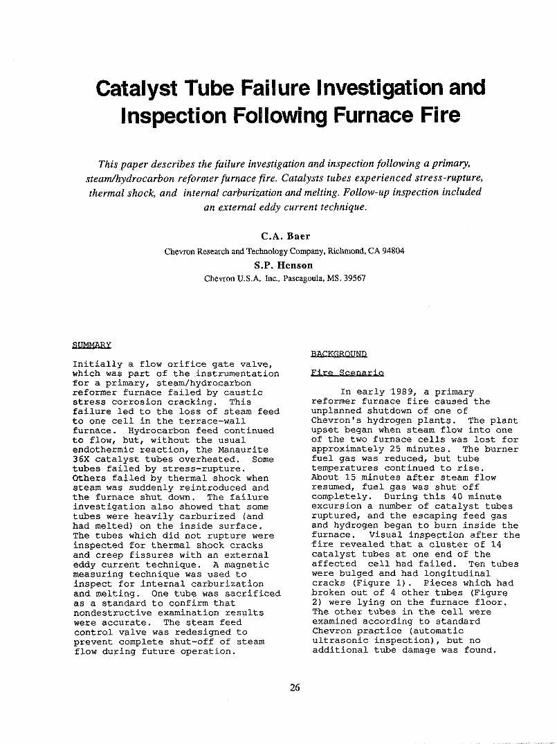
Inside Surface Carburization Ledto Limited Melting. The hydrocarboncracking and coke depositionmentioned earlier created acarburizing atmosphere inside thetubes. As carbon diffused into thetube metal and the carbon contentincreased, the melting point of thestainless steel decreased. When thetube wall temperature rose above1149°C (2100°F), the carburized metalbegan to melt.
This phenomenon wascharacterized by scale, blisters, anda very rough interior surface (Figure9). Chemical analysis showed thatthe scale was carburized Manaurite36X alloy.
The scale had a 4% carboncontent compared to the alloyspecification of 0.35-0.45%. Labtests demonstrated that the meltingpoint of the carburized alloy was1149°C (2100°F) as compared to 1350°C(2460°F) for the non-carburizedalloy.
28

Figure 10 shows the cross-section of a carburized tube sample.We identified three zones parallel tothe surface: typical, carburized, andresolidifled tube metal. The"typical" tube metal had a network ofprimary carbides in the austeniticmatrix. There were no secondarycarbides, indicating the temperatureat this location had exceeded 1260°C(2300°F) . Approaching the surface,the "carburized" zone had increasingnumbers of carbides, as expected fromthe chemical analysis. At thesurface the microstructure containedlarge blocky carbides that no longerformed the primary carbide structurecreated by centrifugal casting. This"resolidified" zone was carburized,melted, and resolidified.
INSPECTION
Unusual Tube Damage Required New NDETechniques
When the laboratoryinvestigation identified thermalshock cracking and inside surfacecarburization in the failed tubes, wedecided that additional inspection ofthe remaining tubes was necessary.Chevron typically uses automaticultrasonic inspection, called CY-1,for hydrogen furnace tube inspection.CY-1 uses ultrasonic attenuation tofind wide, internal, radial-longitudinal cracks, i.e. creepcracks, on the fired side of thetubes. Water-coupled sending andreceiving transducers are mounted onan automatic crawler so that theentire tube length can be inspected.If there is significant signalattenuation indicating creepfissuring, i.e. a tube is "C" rated,radiography is used to determinewhether the tube should be removedfrom service. When the cell was CY-1inspected following the fire, twotubes were "C" rated. Radiography ofthe C rated tubes did not show anyfissures.
Since the thermal shock crackswere fine, surface cracks oriented inmany directions, we were concernedthat CY-1 would not be able to
identify them. Lab tests confirmedour suspicions when CY-1 failed tofind visible thermal shock crackingin pieces of failed tubes. We alsoknow that CY-1 is not designed tolocate inside surface conditions suchas carburization.
While looking for non-destructive ways to identify thermalshock cracks and carburization, weinvestigated two inspection methodsthat were new to Chevron. The firstis an external, automated, eddycurrent inspection technique whichhas been developed in Germany.2 Whenalternating electrical currenttravels through a coil, a magneticfield is induced. Eddy currents areinduced in metals that are exposed tothis magnetic field. The use ofrelatively large diameter coils andlow frequency current generate eddycurrents which penetrate catalysttube walls. Changes in the tubewall's continuity (creep fissures,cracks, weids) will disrupt the eddycurrents. These disruptions aremeasured electronically and displayedon an oscilloscope and chart recorderfor logging and interpretation.
This eddy current (EC) techniquehas some similarities and somedifferences to CY-1. The automated,mechanical procedures are verysimilar. Two EC coils are placed onfired sides of the tube and carriedup and down the tubes by a pneumaticcrawler. One side of the tube isinspected on the way up and the otherside on the way down. The mostsignificant difference between thetwo techniques for our work was thatEC inspection can locate creepfissures and cracks as well as otherradial cracking. EC was able todetect thermal shock cracking inpieces of failed tubes during labtrials. Another notable differenceis that EC does not require acouplant, so no water is used duringthe inspection. This eliminates therefractory damage that can be causedby leaking water. Finally, ECresults are reported as "percent ofwall thickness affected" rather thancategorized.
29

The second inspection method weinvestigated is a manual, magneticdevice called a Carbometer KBZ l3,which detects differences in themagnetic properties of austeniticstainless steels. It was developedto inspect for carburization inethylene furnace tubes, A probecontaining a magnet is held near thetube outer surface and the magneticresponse of the tube is measured.New, austenitic hydrogen reformertubes are non-magnetic, but, as theyage, surface oxidation increasestheir magnetism. In ethylenefurnaces the tubes also become moremagnetic as the internal surfacecarburizes. The Carbometer KBZ l canmeasure these changes, and when theresults are compared to references,the degree of carburization (oroxidation) can be determined.
The eddy current and CarbometerKBZ l inspection techniques seemed tofit our needs for finding creep,thermal shock, and carburization, sowe decided to pursue these optionsfurther. We met with the suppliersfor demonstrations on lab samples aswell as on samples from the fire. Wealso talked with companies in Europewho have used these techniques tolearn about their experiences.Finally, we decided both forms ofinspection plus circumferentialstrapping and radiography would bethe best way to fully characterizethe damage in the furnace.
Results Indicated Additional TubeDamage Limited
During a scheduled shutdownseveral months after the fire, allthe remaining tubes were non-destructively examined and one tubeas removed for destructiveexamination. No tube was condemnedby the inspection, but we did notedamage in a number of tubes.Strapping showed the maximum buigingwas 1.5%. The average for all tubesshowed less than 1% buiging. Forbuiging greater than 3.0%, we requirefurther inspection for creep.
The EC inspection indicated thatnone of the tubes had serious creepor thermal shock cracking. Fivetubes were reported to have creepindications affecting 20-30% of thewall thickness, which was consideredacceptable for continued operation.For this furnace's tube dimensions,indications affecting more than 40%of the wall thickness would requirefurther investigation withradiography. Although it was notrequired, we radiographed several ofthe "worst" locations identified byEC. The x-rays confirmed that nosignificant creep fissures werepresent at these locations.Carbometer KBZ l inspection indicatedthat there had been some level ofcarburization on the inside surfaceof 86 tubes. By using the tubes inthe furnace cell which did not losesteam as references, the inspectorswere able to distinguish abnormallyhigh magnetic response from normalmagnetism caused by oxide formationon the tube's outside surface. Wealso radiographed the areas whichwere most magnetic. The x-raysclearly showed the rough innersurface that developed when thesecarburized tubes melted andresolidified.
In order to further verify theinspection results and evaluate thecarburization damage, we removed onetube for destructive examination.NDE had indicated the tube wascarburized, had resolidified alloy onthe inside surface, and did not havecreep fissuring or thermal shockcracking. A polished and etched tubecross-section confirmed theseconclusions. A 0.140 cm (0.055 in)thick layer of resolidified alloycovered the inner surface. Belowthat the tube wall was carburizedabout 0.020 cm (0.008 in) deep.Isolated creep microvoids could befound at grain boundary triple pointswith high magnification, butsignificant creep damage was notpresent.
30

CONCLUSIONS AND RECOMMENDATIONS
The low pressure tap on theorifice flange failed by causticstress corrosion cracking whichcaused the steam feed control valveto stop steam flow into the furnacecell. Since the control valveclosure was the cause of the furnaceexcursion, the control valve wasaltered so that it cannot stop steamflow completely while the furnace isstill in service.
Loss of steam caused tubes tooverheat and fail by high temperaturehoop stress overload. Other tubesfailed later in the excursion,probably due to thermal shock whenthe furnace was cooling. Many tubeswere also carburized on the innersurface. The failures were notmaterial exclusive. We would haveexpected the same types of failuresfor HK-40 and other HP-modifiedalloys. The 14 failed tubes and twoadditional tubes that had beenremoved were replaced and the furnacereturned to service.
We are unsure how the carburizedlayer on the inside of many tubeswill affect tube life. Heat transferis probably diminished slightly. Thecarburized layer may reduce the creepstrength in the affected tubes as itdoes in ethylene furnaces. However,this should have a limited effect,because the carburization will notcontinue under normal operatingconditions.
In order to allow for thereduced creep strength in thecarburized layer, we recommended thatthe maximum operating temperature bereduced from 959°C (1759°F) to 949°C(1740°F) . The recommendation wasbased on API RP 530 calculations foroperating temperatures and pressuresand minimum wall thickness less thecarburized layer thickness. Theintent was to be able to operate theurnace for five years (until the nextscheduled shutdown) without a creeprupture failure. To date the furnacehas operated over two years since thefire without further incidence.
Since the EC inspection wassuccessful in this furnace, we havecontinued to evaluate its usefulnessin other Chevron hydrogen reformerfurnaces. We have done limitedtesting, but have not yet been ableto make a direct comparison betweenEC and automated ultrasonics.Eventually we hope to have bothtechniques inspect the same furnaceduring the same shutdown in order toevaluate their capabilities.
ENDNOTES
1. Proprietary alloy marketed byManoir Industries
2. Marketed by MagnetischePrüfanlagen GmbH, Reutlingen,Germany
3. Marketed by Manoir Industries
C. A. Baer
S. P. Henson
31

Figure 1. High temperature hoop stress Figure 2. Thermal shock cracking left "blowout"overloading caused "fishmouth" ruptures in 10 faüures in 4 tubes.tubes.
DPTransmitter
STEAM FLOW.
Flow Controller
Failed Gate Valve
ControlValve
FlowOrificePlate
Figure 3. Steam control system.
32

MPa
300-
200-
100.
900
MANAURITE 36X
1000 1100
ksi
43.5
-29.0
-14.5
1200 T°C
Figure 4. High temperature minimum tensile strengths.
Figure 5. Secondary cracks near a "fishmouth"rupture are confined to the primary carbide phase. Figure 6. Typical microstructure for agedLack of directionality and individual creep voids Manaurite 36X shows primary carbides outliningindicate that the cracks are not due to creep. Note an austenitic matrix with scattered secondarythe absence of secondary carbides. carbides.
(Electrolytic oxalic etch, 200X). (Electrolytic oxalic etch, 200X).
33
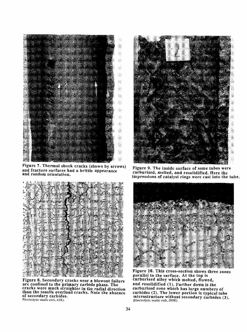
Figure 7. Thermal shock cracks (shown by arrows)and fracture surfaces had a brittle appearanceand random orientatiosi.
Figure 8. Secondary cracks near a blowout failureare confined to the primary carbide phase. Thecracks were much straighter in the radial directionthan the tensile overload cracks. Note the absenceof secondary carbides.Electrolytic oxalic etch, 42X).
Figure 9. The inside surface of some tubes werecarburized, melted, and resolidified. Here theimpressions of catalyst rings were cast into the tube.
Figure 10. This cross-section shows three zonesparallel to the surface. At the top iscarburized alloy wfaicfa melted, flowed,and resolidified (1). Further down is thecarburized zone whicfa has large nuaibers ofcarbides (2). The lower portion is typical tubemicrostructure without secondary carbides (3)(Electrolytic oxalic etch, 200X).
34

DESCUSSION
S. R. G h os h, Krlbhco, Sur at, India: I have two questionsabout the eddy current inspection. We have been doing thisinspection for the last four years. Of course, we have gotHK40 tubes. Our results show that normally you cannot reallycorroborate with the other inspections, like ultrasonic, and alsoby X-rays.The second problem in this case is that the probe covers about66-70% of the area and it does not cover up areas between twotubes. So, what about those portions left out in theinspection?
You see the crawler unit as it goes up. It has got pads onboth sides. So, the pads use an area open from the adjacenttube areas, so about 30-35% of the area is left open. Ourproblem is that we do get signals, we do monitor it, but at thesame time, we cannot really corroborate with any other kind ofStandard inspection, like ultrasonic or X-rays.
So, we acknowledge that it is good technique, but really wehave not been able to make much out of it.
Baer: The ultrasonic technique that we have used has the samesituation. Both techniques only scan the fired sides of thetubes, so there is, indeed, area that is not covered. We havefound that the failures always occur on the fired sides, so we
have not concerned ourselves with not being able to see theshaded sides of the tubes.One of the ideas that we have suggested for further evaluating
the eddy current technique is to use both eddy current andultrasonic inspection in the same furnace in order to comparethe results for accuracy. We have not conducted this test yet.Ghosh: We did some experiments like that by hand heldultrasonic probes. Ours is a top fired furnace, we do not wantto use water because of flooding of the furnace.Conceming the second problem, I feel that you are measuring
magnetic permeability. There also we have some experience. Ifyou have got an F.D. Fan in the steel duet, the corrosionproduct particles keep on accumulating. So the magneticpermeability on the tube surface can be very high by loose rustscale sticking to it.
Since you are introducing this technique we wish to sharewith you that we had found permeability as high as 1.8 wherethe normal should be 1.0-1.02. This was later on foundsuperficial when we ground some part of the weid joint andtube surface ground by 0.5 mm or so it vanished. However,since your tubes are of HP36X you may find higherpermeability due to higher Ni content which may not bealarming.
35