1986-Design of Pervious Pressure Tunnels-Schleiss
8
& DAM CONSTRUCTION Design of pervious pressure tunnels By A. J. Schleiss Reprinted from WATER POWER & DAM CONSTRUCTION May 1986
-
Upload
paulosuperloco -
Category
Documents
-
view
64 -
download
5
Transcript of 1986-Design of Pervious Pressure Tunnels-Schleiss
& DAM CONSTRUCTION
Design of pervious pressure tunnels
By A. J. Schleiss
Reprinted from WATER POWER & DAM CONSTRUCTION May 1986
l1li
I
article presents the summarized results of a study carried out by the author on theinto account seepage forces and secondary permeability in lining and rock. The UUUIILUUIII
traditional tunnel statics" f which assume lining and rock as impervious, is discussed. Newpervious pressure tunnels are recommended.
r1n'pr>t",An for the
the that as long as the11Y\''''''''~'''1f''n" compared with the rockis in lining, accordmctvlining transmits only mechanical nounoarvmass. If the is """"UH'P'U permeableFig. 2) the pressurethe outside of the lining. In theand its reach depends on internal pressurein the rock. A single rock mass elementFig. 2) is loaded on all sides by a U"?'U'r1'O
resulting force (the seepage nrpee11,'p
dimension, like a body quantrtatrveseepage pressures on pressure tunnelsUntil now, these papers have given no inducementing new design procedures for pervious pressure tunnels.
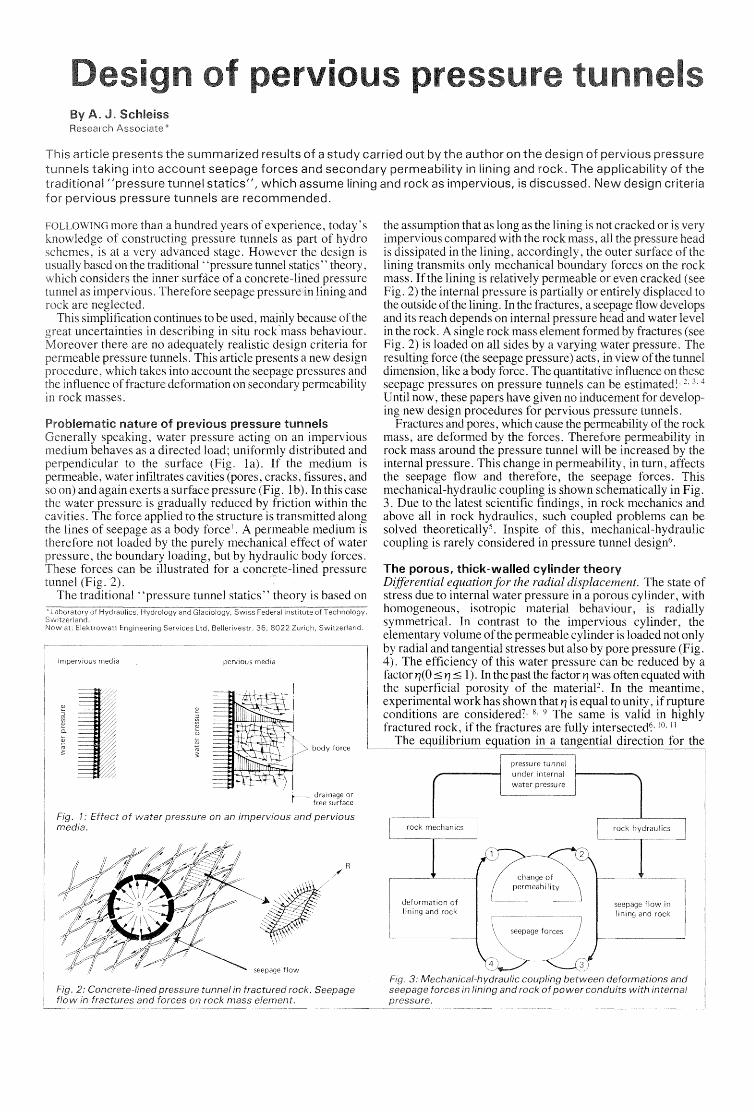
Fractures and pores, which cause the of the rockmass, are deformed by the forces.rock mass around the pressure tunnel will be ' .... r» ..""·"",,'r1internal pressure. This change in permeability, in turn,the seepage flow and therefore, the seepage forces. Thismechanical-hydraulic coupling is shown schematically in Fig.3. Due to the latest scientific findings, in rock mechanics andabove all in rock hydraulics, such coupled can besolved theoretically", Inspite of this,coupling is rarely considered in pressure tunnel
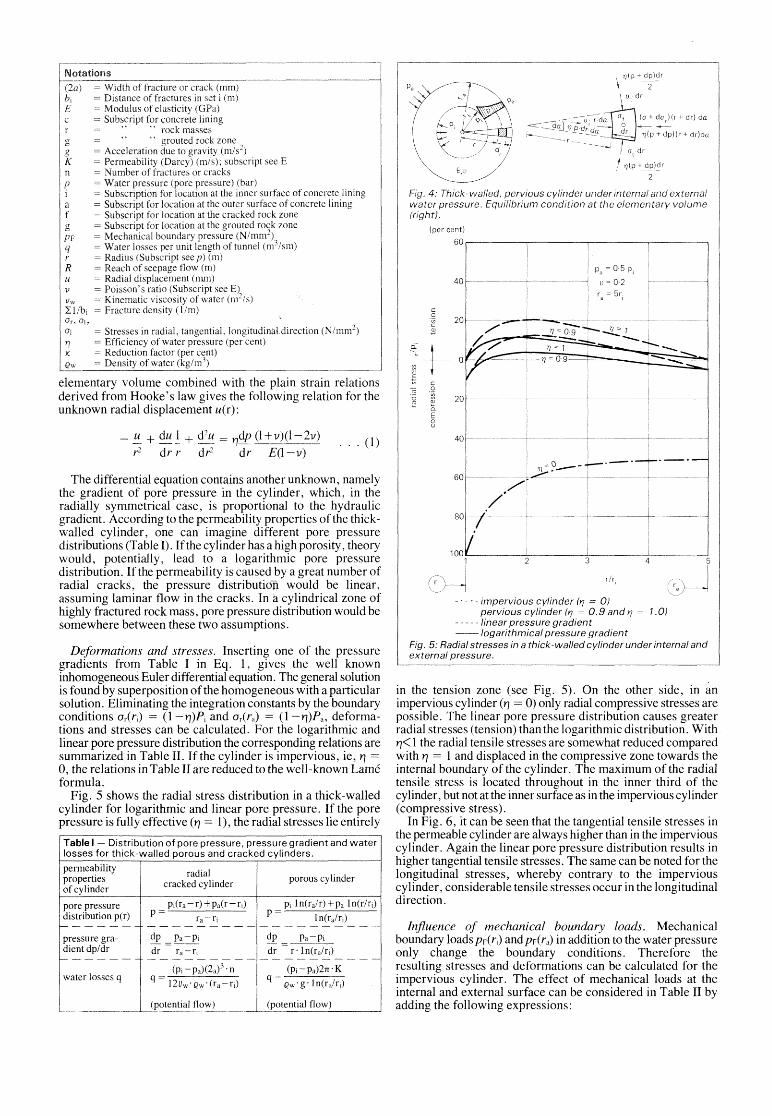
The porous, thick-walled cylinderDifferential equation for the radial The state ofstress due to internal water pressure in a porous cylinder, withhomogeneous, isotropic material behaviour, is radiallysymmetrical. In contrast to the impervious cylinder, theelementary volume ofthe permeable cylinder is loaded not onlyby radial and tangential stresses but also by pore pressure (Fig.4). The efficiency of this water pressure can be reduced byfactor y/(O~ Y/ ~ 1). In the past the factor Y/ was often equated withthe superficial porosity of the material". In the meantime,experimental work has shown that Y/ is equal to unity, if ruptureconditions are considered" 8. 9 The same is valid in highly
I1
",..,,,,,,I,-t,,~C}t-,,",,,,, continues to be used, because oftheuncertainties in describing in situ behaviour.
!\/lr,.. "".,",u,"'" there are no adequately realistic criteria forn""rrnp",lhlp pressure tunnels. This article presents a new design
which takes into account the pressures andinfluence of fracture deformation on permeability
rock masses.
Problematic nature of pressure tunnelsU/-,',<4n,<");;,, water on an impervious
nenaves as a load; uniformly distributed andperpendicular the surface (Fig. la). If the medium ispermeable, water infiltrates cavities (pores, cracks, fissures, and
and again exerts a surface pressure (Fig. 1b). In this casewater pressure is gradually reduced by friction within the
cavities. The force applied to the structure is transmitted alonglines of seepage as a body force I. A permeable medium is
therefore not loaded by the purely mechanical effect of waterthe boundary loading, but by hydraulic body forces.
forces can be illustrated for a concrete-lined pressuretunnel (Fig.
The traditional' 'pressure tunnel statics" theory is based on
pressure on an impervious and pervious1: Effect of
R
rock hydraulics
/ 7](p +
(per cent)
. - impervious cylinder (ry = 0)pervious cylinder (ry 0.9 and rl = 1.0)linear pressure gradient
--Iogarithmical pressure gradientFig. 5: Radial stresses in a thick-walled cylinder under internal andexternal pressure.
Influence of mechanical boundary loads. Mechanicalboundary loads pF(ri) and pF(ra) in addition to the water pressureonly change the boundary conditions. Therefore theresulting stresses and deformations can be calculated for theimpervious cylinder. The effect of mechanical loads at theinternal and external surface can be considered in Table 11 byadding the following expressions:
in the tension zone (see Fig. 5). On the other side, in animpervious cylinder (YJ = 0) only radial compressive stresses arepossible. The linear pore pressure distribution causes greaterradial stresses (tension) than the logarithmic distribution. WithYJ< 1 the radial tensile stresses are somewhat reduced comparedwith YJ = I and displaced in the compressive zone towards theinternal boundary of the cylinder. The maximum of the radialtensile stress is located throughout in the inner third of thecylinder, but not at the inner surface as in the impervious cylinder(compressive stress).
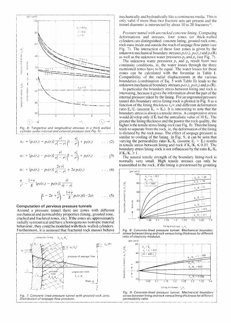
In Fig. 6, it can be seen that the tangential tensile stresses inthe permeable cylinder are always higher than in the imperviouscylinder. Again the linear pore pressure distribution results inhigher tangential tensile stresses. The same can be noted for thelongitudinal stresses, whereby contrary to the imperviouscylinder, considerable tensile stresses occur in the longitudinaldirection.
... (1)
Pi In(ra/r)+Pa In(r/ri)
1n(ra/ri)
porous cylinder
(potential flow)
p
dp pa-pi
dr r'ln(ra/fi)
(Pi-Pa)2rc' Kq Qw' g'ln(ra/ri)
y/dp (1+v)(1-2v)
dr E(1-v)
(potential flow)
radialcracked cylinder
dp pa-pi
dr ra-ri
p
q
~ + du 1 + d2ur2 dr r dr2
water losses q
pressure gradientdp/dr
permeabilitypropertiesof cylinder
pore pressuredistribution per)
The differential equation contains another unknown, namelythe gradient of pore pressure in the cylinder, which, in theradially symmetrical case, is proportional to the hydraulicgradient. According to the permeability properties ofthe thickwalled cylinder, one can imagine different pore pressuredistributions (Table 1). If the cylinder has a high porosity, theorywould, potentially, lead to a logarithmic pore pressuredistribution. If the permeability is caused by a great number ofradial cracks, the pressure distribution would be linear,assuming laminar flow in the cracks. In acylindrical zone ofhighly fractured rock mass, pore pressure distribution would besomewhere between these two assumptions.
Table I Distribution of pore pressure, pressure gradient and waterlosses for thick-walled porous and cracked cylinders.
elementary volume combined with the plain strain relationsderived from Hooke's law gives the following relation for theunknown radial displacement u(r):
Deformations and stresses. Inserting one of the pressuregradients from Table I in Eq. 1, gives the well knowninhomogeneous Euler differential equation. The general solutionis found by superposition ofthe homogeneous with a particularsolution. Eliminating the integration constants by the boundaryconditions Or(n) = (1-YJ)Pi and Or(ra) (1-YJ)Pa, deformations and stresses can be calculated. For the logarithmic andlinear pore pressure distribution the corresponding relations aresummarized in Table 11. If the cylinder is impervious, ie, YJ =0, the relations in Table 11 are reduced to the well-known Lameformula.
Fig. 5 shows the radial stress distribution in a thick-walledcylinder for logarithmic and linear pore pressure. If the porepressure is fully effective (YJ = 1), the radial stresses lie entirely
internal n .. o c:",,, .. ,,
tunnelfunction of theratioboundary stress iswould developgreater the lining trncknesshigher is the tensiletends to from theis the rock mass.similar to cooling of thevarying the ratioin tensile stress between lining and rock if ~ . Theboundary stress lining-rock is not influenced by the ratioif Kc/Kr> l.
The natural tensile strength of the oounoarv 11n"n ....._ ..r'f>v
normally very small. High tensiletransmitted to the if the lining is nrestressed
lining fair,
Fig. 8: Concrete-lined pressure tunnel. Mechanical boundarystress between lining and rock versus lining thickness for differentratio of elasticity modulus.
(per
... (5)
... (4)
rock zone.
r /r.
Computation of pressure tunnelsAround a pressure tunnel there are zones with differentmechanical and permeability properties (lining, grouted zone,cracked and fractured zones, etc). Ifthe zones are approximatelyradially and have a homogeneous isotropic materialbehaviour, they could be modelled with thick-walled cylinders.Furthermore, it is assumed that fractured roC;k masses behave
+
+------"-
linear pore pressure gradient
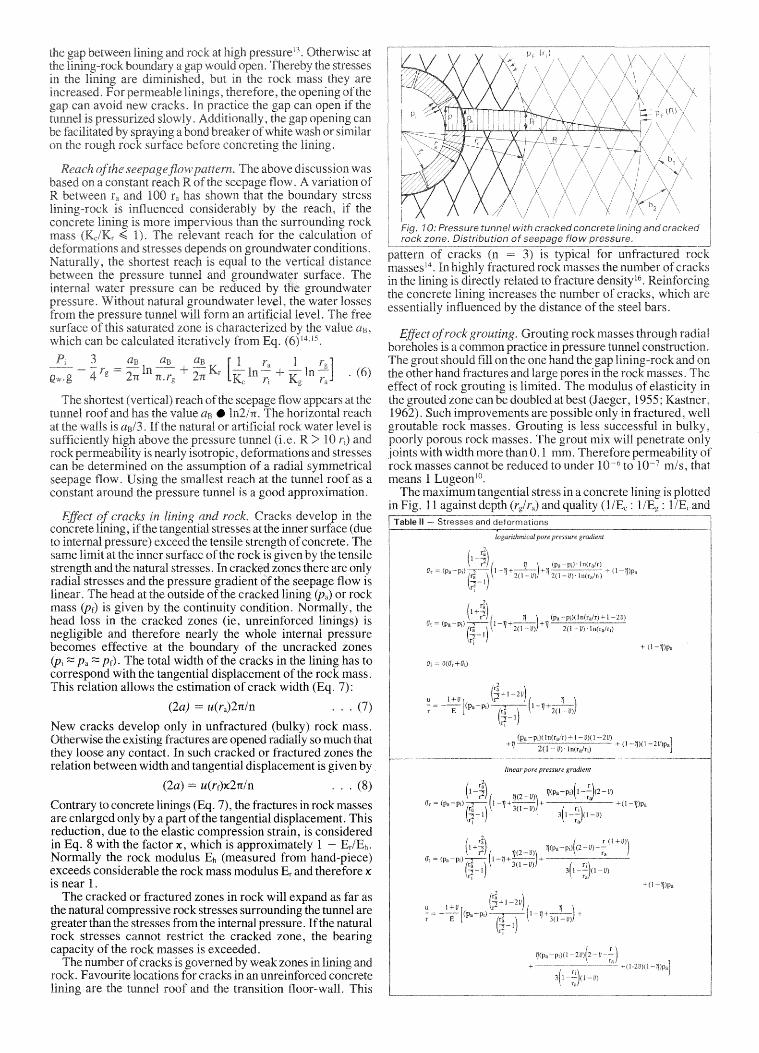
theat the inner (due
strength of concrete. Thethe tensile
onlystresses and the pressure gradient seepage flow isThe head at the outside ofthe cracked lining (pa) or rock
mass is the continuity condition. Normally, thehead in the cracked zones (ie, unreinforced linings) isneatunbte and therefore nearly the whole internal pressurebecomes effective the boundary of the uncracked zones(Pi ::::; p, ::::; Pf). The total width of the cracks in the lining has tocorrespond with the tangential displacement of the rock mass.This relation allows the estimation of crack width (Eq,
(2a) = u(ra)2rr/n . . . (7)
New cracks develop only in unfractured (bulky) rock mass.Otherwise the existing fractures are opened radially so much thatthey loose any contact. In such cracked or fractured zones therelation between width and tangential displacement is given by
(2a) u(rf)x2rr/n ... (8)
Contrary to concrete linings (Eq. 7), the fractures in rock massesare enlarged only by a part of the tangential displacement. Thisreduction, due to the elastic compression strain, is consideredin Eq. 8 with the factor x, which is approximately 1 Er/Eh.Normally the rock modulus Eh (measured from hand-piece)exceeds considerable the rock mass modulus Er and therefore xis near 1.
The cracked or fractured zones in rock will expand as far asthe natural compressive rock stresses surrounding the tunnel aregreater than the stresses from the internal pressure. Ifthe naturalrock stresses cannot restrict the cracked zone, the bearingf"H'V""1h, of the rock masses is exceeded.
number of cracks weak zones andin an unreinforced concretetransition floor-wall.
EE
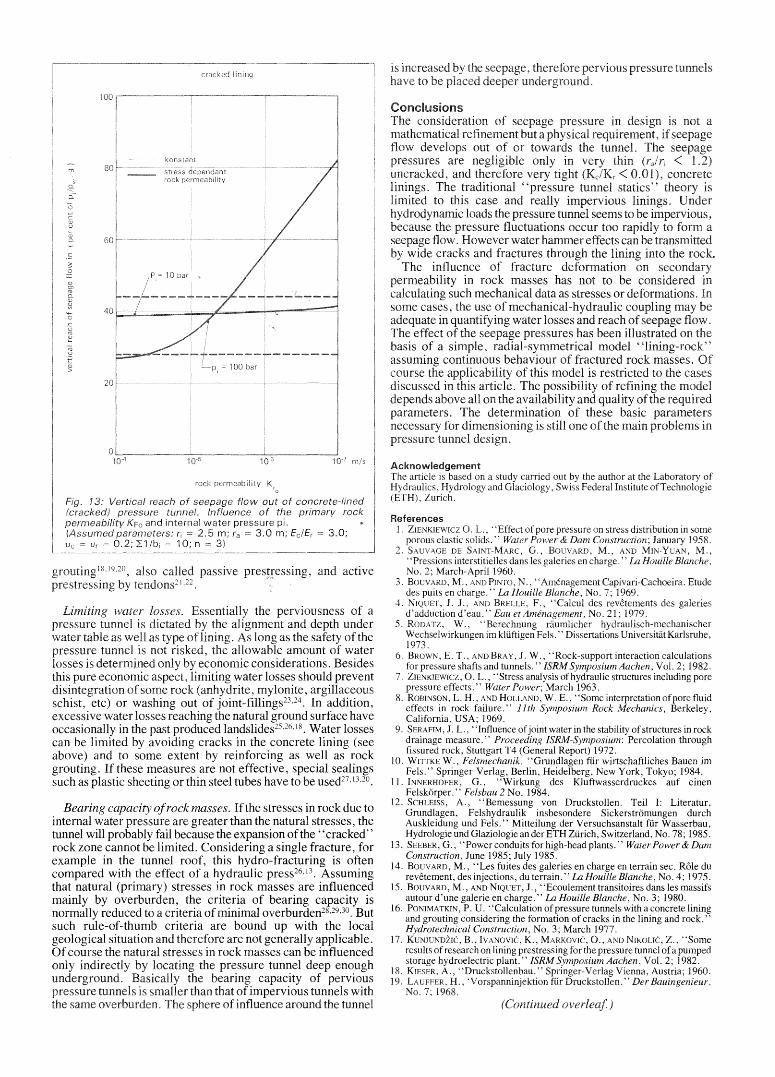
radius r (m) raFig. 12: Distribution of radial displacement in a thick-walled,fractured cylinder. Comparison of deformation-dependent withconstant permeability.(Assumed parameters: E/Pi 1000, U 0.2, Ko = 10- 6 m/s,"L1/bi 10,y/ x 1.0)
Naturally the coupled calculation is only sensible if the permeability properties of the rock masses are known adequately.
Design criteria for pervious pressure tunnelsFor designing pervious pressure tunnels, three criteria areimportant:• Avoiding cracks in the lining;• Limiting water losses;• Ensuring the bearing capacity of the rock masses.Which one of these criteria governs the design in a particular casedepends on the respective boundary conditions.
Avoiding cracks in lining. Cracks in the lining caused byinternal water pressure can be prevented either by reducingforces in lining or by increasing resistance of the lining.Measures for reducing forces in lining are: increasing thicknessof lining, rock grouting, drainage and controlled commencementof operation. These measures are successful only at relativelysmall internal pressure head (Pi <20 bar) and good rock quality(Ei/E, < 3). At higher pressure heads cracks can be avoidedonly by increasing lining resistance, which is possible byprestressing. Different prestressing techniques have beendeveloped: prestressing by rock grouting'? or gap
medium rock
400 1--... ..- ----------+- --..... 1
... (9)
(per cent) r-r-:- -,-- -,
Km + --=---'-'---
6 3 ( 1 1)2Vw ttr 7i; + 7h
K(r)
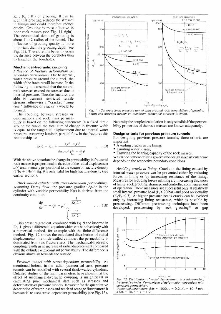
It can be~ .. £,,'tin~ reduces the
in linings and could therefore reducecracks. Grouting is most effective in
rock masses (see Fig. 11 right).economical depth of grouting is
about 1 to 2 radius of the tunnel. Theinfluence of grouting quality is moreimportant than the grouting depth (seeFig. 11). Therefore it is better to lessenthe distance between the boreholes thanto lengthen the boreholes.
Mechanical-hydraulic couplingInfluence of fracture deformation onsecondary permeability. Due to internal.water pressure around the -nmnel, thewidth of the fracture will increase. In thefollowing it is assumed that the naturalrock stresses exceed the stresses due tointernal pressure. Thus the fractures areable to transmit restricted tensilestresses, otherwise a "cracked" zone(see "Influence of cracks") would beformed.
The coupling between stresses ordeformations and rock mass permeability is based on the following statement: In a fixed circlearound the tunnel the total sum of change in fracture widthis equal to the tangential displacement due to internal waterpressure. Assuming laminar, parallel flow in the fractures thisrelationship is:
Thick-walled cylinder with stress-dependant permeability.Assuming Darcy flow, the pressure gradient dp/dr in thecylinder with variable permeability K(r) is derived from thecontinuity condition:
With the above equation the change in permeability in fracturedrock masses is proportional to the cube of the radial displacementu(r) and inversely proportional to the square of fracture density(l/b, + l/b2)2. Eq. 9 is only valid for high fracture density (seeearlier section).
1dpdr - (Pi pal r, ... (10)
f drK(r).r
r.This pressure gradient, combined with Eq. 9 and inserted in
Eq. 1, gives a differential equation which can be solved only witha numerical method, for example with the finite differencemethod. Fig. 12 shows the calculated distribution of radialdisplacements in a thick-walled cylinder; the permeability isdominated from two fracture sets. The mechanical-hydrauliccoupling results in an increase of radial displacement comparedwith the cylinder with constant permeability. The difference isobvious above all towards the outside.
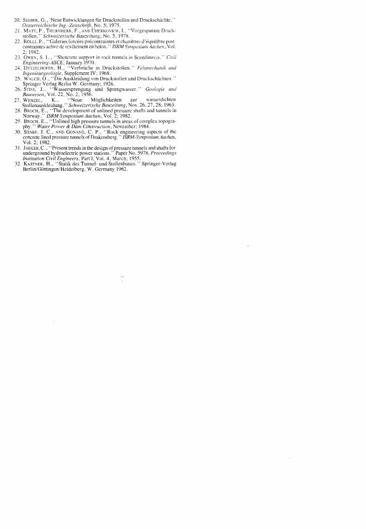
Pressure tunnel with stress-dependant permeability. Asmentioned before, in the radial-symmetrical case, pressuretunnels can be modelled with several thick-walled cylinders.Detailed studies of the main parameters have shown that theeffect of mechanical-hydraulic coupling is insignificant incalculating pure mechanical data such as stresses anddeformations of pressure tunnels. However for the quantitativedescription of water losses and reach of seepage flow pattern itis essential to use a stress-dependant permeability (see Fig. 13).
Laboratory of
ConclusionsThe considerationmathematical rennement
1973.6. BROWN, E. T., AND BRAY ,J. W., "Rock-support interaction calculations
for pressure shafts and tunnels. " ISRM Symposium Aachen , Vol. 2; 1982.ZIENKIEWICZ, O. "Stress of hydraulic structures including porepressure effects." 1963.
8. ROBINSON, L. H. , "Some interpretation of pore fluideffects in rock failure." 11th Rock Mechanics, Berkeley,California, USA; 1969.
9. SERAFIM, J. L., "Influence of joint water in the stability of structures in rockdrainage measure." Proceeding ISRM-Symposium: Percolation throughfissured rock, Stuttgart T4 (General Report) 1972.
10. WITTKE W., Felsmechanik, "Grundlagen fur wirtschaftliches Bauen imFels.' Springer-Verlag, Berlin, Heidelberg, New York, Tokyo; 1984.
11. G. , "Wirkung des Kluftwasserdruckes auf einenFelskorper. Felsbau 2 No. 1984.
12. SCHLEISS, A., "Bemessung von Druckstollen. Teil I: Literatur,Grundlagen, Felshydraulik insbesondere Sickerstromungen durchAuskleidung und Fels." Mitteilung der Versuchsanstalt fur Wasserbau,Hydrologie und Glaziologie an der ETH Zurich, Switzerland, No. 78; 1985.
13. SEEBER, G., "Power conduits for high-head plants." Water Power & DamConstruction, June 1985; July 1985.
14. BouvARD, M., "Les fuites des galeries en charge en terrain sec. Role durevetement, des injections, du terrain." In Houille Blanche, No. 4; 1975.
15. BOUVARD, M., AND NIQUET, J., "Ecoulernent transitoires dans les massifsautour d'une galerie en charge." In Houille Blanche, No. 3; 1980.
16. PONIMATKIN, P. U. "Calculation of pressure tunnels with a concrete liningand grouting considering the formation of cracks in the lining and rock. "Hvdrotechnical Construction, No. 3; March 1977.
17. KUNJUNDZIC, IVANOVIC, K., 0., AND
storage hydroelectric18. KIESER, A., "Druckstollenbau.19. H., 'Vorspanninjektion
No.
and active
Ee/Er 3.0;
Bearing capacity ofrock masses. Ifthe stresses in rock due tointernal water pressure are greater than the natural stresses, thetunnel will probably fail because the expansion of the "cracked"rock zone cannot be limited. Considering a single fracture, forexample in the tunnel roof, this hydro-fracturing is oftencompared with the effect of a hydraulic press": 13. Assumingthat natural (primary) stresses in rock masses are influencedmainly by overburden, the criteria of bearing capacity isnormally reduced to a criteria of minimal overburden28,29,3o . Butsuch rule-of-thumb criteria are bound up with the localgeological situation and therefore are not generally applicable.Of course the natural stresses in rock masses can be influenced
locating the tunnel deep enoughcapacity of
'rI'\1'\""rUl'Ar.c tunnels withof influence around the tunnel
losses. of apressure tunnel is dictated and depth underwater table as well as long as the safety of thenr~'CC'lT'''' tunnel is not the allowable amount of water
determined only by economic considerations. Besideslimiting water losses should
r!1c,,,,,t,,,,,,,'r<:>t',nn ofsome (anhydrite, rI'\'I'lrwl1t""
etc) or washing out of joint-fillings">'. In addition,water losses reaching the natural ground surface have
occasionally in the past produced landslides-l-":". Water lossescan be limited avoiding cracks in the concrete lining (seeabove) and to some extent by reinforcing as well as rockgrouting. If these measures are not effective, special sealingssuch as plastic sheeting or thin steel tubes have to be used27,13,2o .
Scandinavia. "
in Druckstollen.' undtngenieurueotogte . Supplement IV; 1968.
Auskleidung von Druckstollen und Druckschachten."Verlag Berlin W. Germany; 1926.
26. J., "Wassersprengung und Sprengwasser." GeologieBauwesen, Vol. 22, No. 2; 1956.WENZEL, K., "Neue Moglichkeiten zur wasserdichtenStollenauskleidung." Nos. 26,27,28; 1963.
28. BROCH, E., "The development of unlined pressure shafts and tunnels inNorway." ISRM Symposium Aachen, Vol. 2; 1982.BROCH, E., "Unlined high tunnels in areasphy." Water Power & Dam November;
30. SHARP, J. C., AND GONANO, C. P., ingconcrete lined pressure tunnels of Drakensberg. " IS1W-SymposiumVol. 2; 1982.
31. JAEGER, C., "Present trends in the design of pressure tunnels and shafts forunderground hydroelectric power stations. " Paper No. 5978, ProceedingsInstitution Civil Engineers, Part I, Vol. 4, March; 1955.
32. KASTNER, H., "Statik des Tunnel- und Stollenbaues." Springer-VerlagBerlin/Gottingen/Heidelberg, W. Germany 1962.