1982 OPERATOR6S MANUAL - Elyon School & Child … Nordik Skandic.pdf• Vehicles used for racing...
44
1982 OPERATOR6S MANUAL NORDIK* SKANDIC* ® * Trademarks of Bombardier Inc. Litho'd in Canada All rights reserved © BombardierInc. 414472700
Transcript of 1982 OPERATOR6S MANUAL - Elyon School & Child … Nordik Skandic.pdf• Vehicles used for racing...

1982OPERATOR6S
MANUAL
NORDIK*SKANDIC*
® * Trademarks of Bombardier Inc.
Litho'd in Canada All rights reserved © BombardierInc. 414472700

model
V.I.N.
purchase date _
warranty expiry date
To be completed by dealer at time of sale
DEALER IMPRINT AREA
MOTO-SKIFUTURASPIRITNUVIKMIRAGESUPER SONICULTRA SONICSONIC
TECHNICAL PUBLICATIONSAFTER SALES SERVICEBOMBARDIER INC.VALCOURT, QUEBECCANADA, JOE2LO
The following are trademarks of Bombardier Inc.BOMBARDIER EVERESTSKI-DOO CITATIONALPINE OLYMPIQUEBLIZZARD T'NTCARRY-BOOSE NORDIKELAN SKANDICELITEGRAND PRIX SPECIAL

FOREWORD
The Operator Manual and the Snowmobile Safety handbook have beenprepared to acquaint the owner / operator of a new snowmobile with the various vehicle controls maintenance andsafe operating instructions. Each is indispensable for the proper use of theproduct, and should be kept with thevehicle at all times.
Should you have any questions pertaining to the warranty and its application, please consult the "Often AskedQuestion" section of this manual, oryour selling dealer.
This manual uses the following sym-bols. .
• WARNING: Identifies an instruc~ tion which, if not followed, couldcause personal injury.
... CAUTION: Denotes an instruc... tion which, if not followed, could
severely damage vehicle components.
O NOTE: Indicates supplementaryinformation needed to fully com
plete an instruction.
Although the mere reading of such information does not eliminate the hazard, your understanding of the information will promote its correct use.
Most specifications are given in both metric and customary units. Where preciseaccuracy is not required, some conversions are rounded to even numbers foreasier use.
A shop manual can be obtained for complete service, maintenance and repair information.

SAFETY IN MAINTENANCE
Observe the followingprecautions:• Throttle mechanism should be
checked for free movement beforestarting engine.
• Engine should be running only whenpulley guard is secured in place.
• Never run the engine without drivebelt installed. Running an unloadedengine can prove to be dangerous.
• Never run the engine when the trackis raised off the ground.
• It can be dangerous to run enginewith the hood removed.
• Gasoline is flammable and explosiveunder certain conditions. Alwaysmanipulate in a well ventilated area.Do not smoke or allow open flamesor sparks in the vicinity. If gasolinefumes are noticed while driving, thecause should be determined andcorrected without delay.
• Maintain your vehicle in top mechanical condition at all times.
• Your snowmobile is not designed tobe driven or operated on black top,bare earth, or other abrasive surfaces. On such surfaces abnormaland excessive wear of critical partsis inevitable.
• Your snowmobile is not designed tobe operated on public streets, roador highways. In most States andProvinces, it is considered an illegaloperation.
• Installation of other than standardequipment, including ski-spreaders,bumpers, pack racks, etc.. couldseverely affect the stability and safety of your vehicle. Avoid adding onaccessories that alter the basic vehicle configuration.
• The snowmobile engine can bestopped by activating the emergency cut-out switch, tether switch orby turning off the key.
• Whenever the vehicle is parked outdoors, overnight or for a long period, it issuggestedto protect it againstthe inclemency of the weather witha snowmobile cover.
• Do not lubricate throttle and/orbrake cables and housings.
• Only perform procedures as detailedin this manual. Unless otherwisespecified, engine should be turnedOFF for all lubrication and maintenance procedures.
• Clean and check operation of theheadlight, taillight and brake light.
• PLEASE READ AND UNDERSTANDALL WARNINGS AND CAUTIONSIN THIS MANUAL AND ON THEVEHICLE.
Thisvehicle is builtwith parts dimensioned in the metric system. All fasteners aremetric and must not be replaced by customary fasteners. Mismatched or incorrect fasteners could cause damage to the vehicle orpossible personal injury.
THIS MANUAL SHOULD REMAIN WITH THE VEHICLE ATTHE TIME OF RESALE.
2

INDEX
THE 1982 "LIMITED WARRANTY" . . . . . . . . . . . . . .. . 4
OFTEN ASKED QUESTIONS 8
LISTING OF AREA DISTRIBUTORS 8
HOW TO IDENTIFY YOUR SNOWMOBILE . . . . . . . . . . . . . . . . . . . . . . . .. . .9
CONTROLs/INSTRUMENTSThrottle lever, brake lever, parking brake, ignition light switch, headlamp dimmerswitch, emergency cut-out switch, manual starter, handle, primer, tether cut-outswitch, speedometer, trip meter, reset button, horn, hood opening, tool box, fuelgauge, spark plug holder! spare drive belt, hitch, ski tie down. . . . . . . .. . ... .10
BREAK-IN PERIODBreak-in! inspection 10-hour j inspection checklist. . ... ... . .. .... .13
FUELRecommended gasoline! recommended oil, fuel mixture ratio, fuel mixing proce-dure, fuelloil mixing chart. . .. . 15
PRE-START CHECKCheck points 17
STARTING PROCEDUREManual starting, emergency starting. . . . . . . . . . .. .... . . . . . .. .... . ... 17
LUBRICATIONFrequency, steering mechanism, chaincase oil level, drive axle, suspension. .19
MAINTENANCEChart, drive belt, new drive belt, pulley guard removal, drive belt removal & installation, brake condition, brake adjustment, brake light switch adjustment,spark pluqts), track condition, track tension and alignment, suspension condition, suspension adjustment, drive pulley, steering mechanism, steering adjustment, muffler attachment carburetor adjustment, fan belt engine head nuts, engine mount nuts, headlamp beam aiming, bulb replacement, general inspec-tion. . . . . . . . . .. . 21
STORAGETrack! suspension, skis, controls, chaincase, drive pulley, fuel tank and carbure-tor, cylinder lubrication, chassis, general inspection 30
PRE-SEASON PREPARATIONPre-season preparation chart 32
TROUBLE SHOOTING GUIDE 34TOOLS 38SPECIFICATIONS. . . . . . . .. . 37WIRING DIAGRAMS. . . . . . . . . . . . . . . . . . . . . . . . . . . . . . . . . . . . .. . 39SI METRIC INFORMATION GUIDE . . . . . . .. . . . 40CHANGE OF ADDRESS OF OWNERSHIP 41
3

LIMITED WARRANTY 1982 SKI-DOO® SNOWMOBILES
1 . PERIODBOMBARDIER® INC. as manufacturer, warrants FROM THE DATE OF FIRSTCONSUMER SALES, every 1982 SKI-DOO® snowmobile, sold as NEW AND UNUSED, by an authorized SKI-DOO dealer, for periods of:
• 12 consecutive months for ELAN®, CITATION*, EVEREST®, ELlTE®,ALPINE® models.
• 90 consecutive days for NORDIK*, SKANDIC*, BLiZZARD® 5500 MX and 9500models subject to the following:
1. If delivery is made after the 31st day of March of a given year and before the 1stday of December of the same year, the above 90 day warranty will start on December 1st.
2. If delivery is made on/or after the 2nd day of January of a given year but beforethe 31st day of March of the same year, all the unused portion of the 90 day period will be carried over to the next winter and start again on the 1st day of December of the same year.
2· WHAT BOMBARDIER WILL DOBOMBARDIER will repair and/or replace, at its option, components defective inmaterial and/or workmanship (under normal use and service,) with a genuineBOMBARDIER component without charge for parts or labour, at any authorizedSKI-DOO dealer during said warranty period.
3 - CONDITION TO HAVE WARRANTY WORK PERFORMEDPresent to the servicing dealer, the hard copy of the BOMBARDIER Customer Registration card received by the customer from the selling dealer at time of purchase.
4 • WARRANTY TRANSFERThis warranty is transferable to subsequent ownertsl for remainder of warranty period from original date of sale.
5 · EXCLUSIONS · ARE NOT WARRANTED• Normal wear on all items such as, but not limited to:
- drive belts- slider shoes
spark plugs- breaker points- runners on skis
• Replacement parts and/or accessories which are not genuine BOMBARDIERparts and/or accessories.
• Damage resulting from installation of parts other than genuine BOMBARDIERparts.
• Damage caused by failure to provide proper maintenance as detailed in theOperator Manual. The labour, parts and lubricants costs of all maintenance services, including tune-ups and adjustments will be charged to the owner.
• A sulphated battery.
4
• Vehicles used for racing purposes.
• All optional accessories installed on the vehicle.(The normal warranty policy for parts and accessories, if any, applies).
• Damage resulting from accident, fire or other casualty, misuse, abuse or neglect.
• Damage resulting from modification to the snowmobile not approved in writingby BOMBARDIER.
• Losses incurred by the snowmobile owner other than parts and labour, such as,but not limited to, transportation, towing, telephone calls, taxis, or any other incidental or consequential damages.
Some states or provinces do not allow the exclusion or limitation of incidental or consequential damages, so the above limitation or exclusion may notapply.
8 . EXPRESSED OR IMPLIED WARRANTIESThis warranty gives you specific rights, and you may also have other legalrights which may vary from state to state, or province to province. Where applicable this warranty is expressly in lieu of all other expressed or impliedwarranties of BOMBARDIER, its distributors and the selling dealer, inclUdingany warranty of merchantability of fitness for any particular purpose; othe....wise the implied warranty is limited to the duration of this warranty. However, some states or provinces do not allow limitations on how long an implied warranty lasts, so the above limitation may not apply.Neither the distributor, the selling dealer, nor any other person has beenauthorized to make any affirmation, representation or warranty other thanthose contained in this warranty, and if made, such affirmation, representation or warranty shall not be enforceable against BOMBARDIER or any otherperson.BOMBARDIER INC. reserves the right to modify its warranty policy at anytime, being understood that such modification will not alter the warrantyconditions applicable to vehicles sold while the above warranty is in effect.
7 - CONSUMER ASSISTANCEIf a servicing problem or other difficulty occurs, we suggest the following:
1. Try to resolve the problem at the dealership with the Service Manager orOwner.
2. If this fails, contact your area distributor listed in the Operator Manual.
3. Then if your .grievance still remains unsolved, you may write to us:
Bombardier Inc.Service DepartmentRecreational ProductsValcourt, Quebec, Canada, JOE 210
January 1981Bombardier Inc.Valcourt, Quebec, Canada,·JOE 210
"Trademarks of Bombardier Inc.
5

OFTEN ASKED QUESTIONS
Q: Why must my snowmobile be registered? After alii do have my original invoiceas proof of when I purchased my snowmobile.
A. Your warranty is valid at any authorized dealer of the product. Your registration is the key element in providing the servicing dealer with the necessarydata to complete warranty claim forms. This information is also used to notifyowners in the event of a safety recall.
Q: How do I know my vehicle has been registered at the factory?
A: When you bought your snowmobile the dealer should have completed, andforwarded us the manufacturer's copy of the Customer Warranty Registration. YOUR DEALER SHOULD HA VE GIVEN YOU THE HARD COpy OF THEWARRANTY REGISTRATION FORM.
Q: I bought my snowmobile in O'King County but I snowmobile in WashingtonCounty. Can the dealer in Washington County accept to perform warranty workon my snowmobile?
A: Yes, any authorized dealer in North America can perform warranty repairs,providing the customer warranty registration card is presented.
Q: Where can I find information on the lubrication and maintenance of my snowmobile?
A. In this Operator Manual provided with the vehicle at the time of first sale.
Q: Will the entire warranty be void or cancelled, if I do not operate or maintain mynew snowmobile exactly as specified in the Operator's Manual?
A: The warranty of the new snowmobile cannot be "Voided" or "Cencetted".However, if a particular failure is caused by operation or maintenance otherthan is shown in the Operator Manual, THA T failure may not be covered underwarranty. This includes service work performed by the customer, especiallythe critical adjustments to ignition, timing, carburation and oil injection/or oilmixture.
Q: Would you give some examples of abnormal use or strain, neglect or abuse?
A: These terms are general and overlap each other in areas. Some specific examples may include: running the machine out of oil, chain failure caused by alack of lubrication, operating the machine with a broken or damaged partwhich causes anotherpart to fail, and so on. If you have any specific questionson operation or maintenance, please contact your dealer for advice.
6

Q: What costs are my responsibility during the warranty period?
A: The customer's responsibility includes all costs of normal maintenance services, non-warranty repairs, accidents and collision damage, as well as oils,and spark plugs, and incidental or consequential damages costs as explainedin the warranty.
Q: Are "Genuine" Bombardier replacement parts used in warranty repairs coveredby warranty?
A: Yes. When installed by an authorized dealer, any "genuine" Bombardierpart used in warranty repairs assumes the remaining warranty that exists onthe machine.
Q: If I sell my snowmobile within the warranty period, will the new owner qualifyfor the balance of the warranty?
A: Yes, provided the unit has already been registered with the manufacturer.Note that the change of ownership card in this manual should be completedand sent to Bombardier Inc.
Q: How can I receive the best owner assistance?
A: The satisfaction and goodwill of the owners of Bombardier products are ofprimary concern to your dealer and Bombardier Inc. Normal/y, any problemsthat arise in connection with the sales transaction or the operation of yoursnowmobile will be handled by your Dealers Sales or Service Departments. Itis recognized, however, that despite the best intentions of everyone concerned, misunderstandings will sometimes occur. If you have a problem that hasnot been handled to your satisfaction through normal channels, we suggestthat you discuss your problem with a member ofdealership management Frequently, complaints are the result ofa breakdown in communications and canquickly be resolved by a member of the dealership management. If the problem already has been reviewed with the Sales Manager or Service Manager,contact the Dealer himself or the General Manager.
7

LISTING OF AREA DISTRIBUTORS
CANADIAN DISTRIBUTORS
ALPINE DISTRIBUTORS LIMITEDKalamalka Lake RoadP.O. Box 159Vernon, British Columbia, V1T 6M2(604) 545-1314British Columbia
BOMBARDIER INC.EASTERN CANADA DISTRIBUTIONDIVISIONAtlantic BranchP.O. Box 670Shediac, New Brunswick, EOA 3GO(506) 532-4454Magdalen Island, Nova Scotia, NewBrunswick, Prince Edward Island
BOMBARDIER INC.EASTERN CANADA DISTRIBUTIONDIVISION(Quebec Branch)1350 Nobel BoulevardBoucherville, Quebec, J4B 1A 1(514) 527-2469 or 655-6121Province of Quebec
BOMBARDIER INC.EASTERN CANADA DISTRIBUTIONDIVISIONOntario Branch230 Bayview DriveBarrie, Ontario, L4N 4Y8(705) 728-8600Province of Ontario
BROOKS EQUIPMENT LIMITED1616 King Edward StreetP.O. Box 985Winnipeg, Manitoba, R3C 2V8(204) 633-7247Manitoba, Saskatchewan
HUDSON'S BAY CO. LTD.165 Hymus BlvdPointe-Claire. Quebec, M4W 1A8(514) 697-8500North-West Territories, FranklinDistrict & Keewatin
8
J.W. RANDALL LIMITEDWest StreetP.O. Box 1050Corner Brook, Newfoundland, A2H 6G7(709) 634-3533Newfoundland, Labrador
TRACT EQUIPMENT14325, 114th AvenueEdmonton, Alberta, T5M 2Y8(403) 452-9910Alberta, Dist. Mackenzie, Yukon,N.W.T.
AMERICAN DISTRIBUTORS
BOMBARDIER CORPORATION4505 West Superior StreetP.O. Box 6106Duluth, Minnesota 55806(218) 628-2881North Dakota, Minnesota, Wisconsin,Illinois, Missouri, Michigan, Indiana,Ohio (less eastern half), Tennessee,Kentucky, West Virginia, Virginia,Northern Idaho, Northern Wyoming,Montana, Iowa, Washington.
ELLIOTT & HUTCHINS INC.East Main Street RoadMalone, N~w York 12953(518) 483-4411New York, Massachusetts, Connecticut, Rhode Island, Pennsylvania,New Jersey, Maryland, Delaware,District of Columbia, Eastern half ofOhio, Maine, New Hampshire, Vermont.
MILLER EQUIPMENT ANDRECREATIONAL CENTER1049 Whitney RoadAnchorage, Alaska 99501(07) 274-9513Alaska

HOW TO IDENTIFY YOUR SNOWMOBILE
The main components of your snowmobile (engine, track and frame) areidentified by different serial numbers. Itmay sometimes become necessary tolocate these numbers for warranty purposes or to trace your snowmobile inthe event of theft.
O NOTE: We strongly recommend that you take note of all the serial numberson your vehicle and supply them to your insurance company. It will surely
help in the event a snowmobile is stolen.
9
CONTROLS/INSTRUMENTS
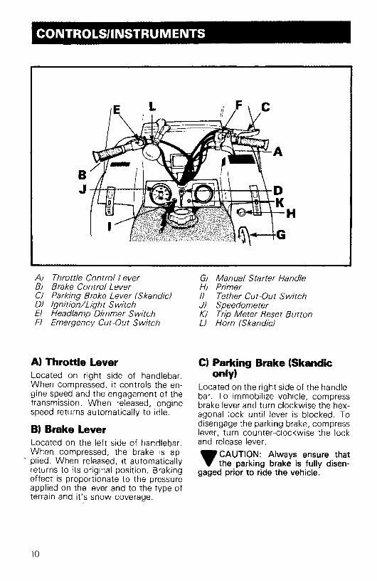
A) Throttle Control LeverBJ Brake Control LeverCJ Parking Brake Lever (Skendic)DJ Ignition/Light SwitchEJ Headlamp Dimmer SwitchFJ Emergency Cut-Out Switch
A) Throttle LeverLocated on right side of handlebar.When compressed, it controls the engine speed and the engagement of thetransmission. When released, enginespeed returns automatically to idle.
B) Brake LeverLocated on the left side of handlebar.When compressed, the brake is ap-
- plied. When released! it automaticallyreturns to its original position. Brakingeffect is proportionate to the pressureapplied on the lever and to the type ofterrain and it's snow coverage.
10
GJ Manual Starter HandleH) Primer/) Tether Cut-Out SwitchJ) SpeedometerKJ Trip Meter Reset ButtonLJ Horn (Skendic)
C) Parking Brake (Skandiconly)
Located on the right side of the handlebar. To immobilize vehicle, compressbrake lever and turn clockwise the hexagonal lock until lever is blocked. Todisengage the parking brake, compresslever! turn counter-clockwise the lockand release lever.
.,CAUTION: Always ensure that"Y the parking brake is fully disen
gaged prior to ride the vehicle.

D} Ignition/Light Switch
OFF
Key operated, 2 position switch. Tostart engine, first turn key clockwise toON position. To stop engine, turn keycounter-clockwise to OFF position.
The lights are automatically ON whenever the engine is running.
......WARNING: If the switch has"'been used in an emergency situation the source of malfunction shouldbe determined and corrected before restarting engine.
G) Manual Starter HandleAuto rewind type located on right handside of vehicle. For proper operation I
refer to Starting Procedure p. 16.
H) PrimerA push-pull button. Pull and push button (2-3 times) to activate primer. Theprimer should always be used for coldengine starts. After engine is warmhowever, it is not necessary to useprimer when starting.
I} Tether Cut-Out SwitchAttach tether cord to wrist or otherconvenient location then snap tethercut-out cap over receptacle beforestarting engine.
IAttach to
wrist -
1J~
If emergency engine "shut off" is required, completely pull cap from safetyswitch and engine power will be automatically shut /I off".
O NOTE: The cap must be installedon the safety switch at all times in
order to operate the vehicle.
...... WARNING: If the switch is used
... in an emergency situation thesource of malfunction should be determined and corrected before restartingengine.
" ON
E} Headlamp Dimmer SwitchThe dimmer switch, located on leftside of handlebarI allows correct selection of headlamp beam. To obtain highor low beam simply flick switch.
F) Emergency Cut-Out Switch
A 3 position switch located on the rightside of the handlebar. To stop the engine in an emergency, flick the lever toeither upper or lower HOFF" position.To start engine, lever must be in middle HaN" position.
...... WARNING: For safety reasons,....the emergency cut-off switch iseasily accessible; be careful not tooperate it inadvertently.
The driver of this vehicle should familiarize himself with the function of thisdevice by using it several times on firstouting. Thereby being mentally prepared for emergency situations requiring its use.
11

J) SpeedometerThe speedometer is linked directly tothe drive axle. Direct-reading dial indicates the speed of the vehicle. Odometer records the total distance travelled.
K) Trip Meter Reset ButtonTo reset trip meter to zero, turn buttoncounter-clockwise until all numbersread zero.
U Horn (Skandic only)Located on the left side of the handlebar. Press firmly to operate.
Hood OpeningPull down the latches to unlock thehood from the anchor.
O NOTE: Always lift hood gently upuntil stopped by restraining de
vice .
•WARNING: It is dangerous to runan engine with the hood open un
fastened or removed. Personal injurycould result.
ToolBoxLocated under the hood. To gain access, tilt hood. Ideal location for sparerope, first aid kit, flash-light, etc ...
Spark Plug HolderSpare spark plugs can be carried in thespecial holes in the air silencer.
12
Fuel GaugeUnscrew fuel tank cap and withdrawdipstick to check fuel level.
•WARNING: Never use a lit matchor open flame to check fuel level.
Spare Drive BeltCan be installed in belly pan clip.
•WARNING: Always be careful notto burn yourself on the exhaust
system when removing or installingdrive belt.
Hitch
Fixed on the rear bumper, the hitch hastwo attachment points. A hook typeand a plate type. A hair pin is suppliedto lock the hook type attachment .
•WARNING: When towing a sledor trailer, always ensure to lock
the hook or plate type attachment withthe hair pin.

Trailers or sleds towed behind a snowmobile should always be loaded withthe lowest possible center of gravity.Use a rigid tow bar when pulling a towsled behind your snowmobile. Whenyou are pulling passengers in a traileror tow sled, use moderate speed andavoid rough terrain for their safety.Also, have all passengers get out of atowed vehicle and walk across allroads. Each towed vehicle should havereflectorized material on each side andon the rear.
Skis Tie Down (Skandic Only)Two straps are fixed on each side ofthe frame above the footboard to securely attach a pair of skis.
·........-~"Skistie down--......--...:'
BREAK-IN PERIOD
Break-inWith Bombardier-Rotax snowmobileengines, a break-in period is requiredbefore running the vehicle at full throttle. Engine manufacturer recommendation is 10 to 15 operating hours.Maximum throttle should not exceed3/4, however, brief full accelerationand speed variations contribute to agood break-in. Continued wide openthrottle accelerations, prolonged cruising speeds, and lugging are detrimental during the break-in period.
ONOTE: A new drive belt requiresa break-in period of 15-25 km (10
15 miles).
10-Hour InspectionAs with any precision piece of mechanical equipement, we suggest that afterthe first 10 hours of operation or 30days after the purchase, whichevercomes first, that your vehicle be checked by your dealer. This inspection willgive you the opportunity to discuss theunanswered questions you may haveencountered during the first hours ofoperation.
The 10 hours inspection is at the expense of the vehicle owner.
13

10·HOUR INSPECTION CHECK LIST .fEngine timing
Fan belt tension
Spark plug(s) condition: (Remove and clean)
Carburetor adjustment
Engine head nuts
Engine mount nuts
Muffler attachment
Chaincase oil level
Brake operation and lining condition
Ski alignment (runner condition)
Steering arm, retorque to 42 N-m (31 ft-lbs)
Handlebar bolts, retorque to 26 N-m (19 ft-Ibs)
Pulley alignment and drive belt condition
Track condition, tension and alignment
Lubrication (steering, suspension, drive axle)
Electrical wiring (loose connections, stripped wires, damaged insula-tion), tighten aU loose bolts, nuts and linkage
Operation of lighting system (HI / LO beam, brake light, etc.), testoperation of emergency cut-out switch and tether switch
We recommend that you have your dealer sign this inspection.
Date of 10 hour inspection
14
Dealer signature

FUEL MIXING
Oil must be added to the gasoline inpre-measured amounts then both oiland gasoline should be thoroughlymixed together before fueling the tank.
Recommended GasolineUse regular leaded or unleaded gasoline available from all service stations.
... CAUTION: Never experiment with.. different fuel or fuel ratios. Never
use naphtha, methanol, gasohol orsimilar products.
Recommended OilUse concentrated Bombardier snowmobile oil available from your dealer.This type of oil has specially formulated oil bases to meet the lubricationrequirements of the Bombardier-Rotaxengine.
If Bombardier snowmobile oil is unavailable, substitute with a high-quality2 cycle snowmobile oil. Seeoil manufacturer recommendations on container .
... CAUTION: Never use outboard.. or straight mineral oils.
Fuel Mixture RatioThe importance of using the correctfuel mixture cannot be overstressed.An incorrect fuel ratio results in seriousengine damage. Recommended fuel ratio is 50/1 (40/1 during break-inad),
SI UNITS
500 mL oil to 25 liters = 50/1
IMPERIAL UNITS1 can 16 oz oil to 5 imp. gals = 50/1or1can 5CX) mL oil to 51/2 imp. gals= 50/1
U.S. UNITS
1 can 12 oz oil to 5 U.S. gals= 50/1
O NOTE: To facilitate fuel mixing oilshould be kept at room tempera
ture.
Fuel Mixing ProcedureTo mix the gasoline and oil always usea separate clean container. Never mixdirectly in your snowmobile tank. Forbest results, acquire two containers,either plastic or metal. Draw from oneuntil empty then use the second one.
+WARNING: Gasoline is flammable and explosive under certain
conditions. Always manipulate in awell ventilated area. Do not smoke orallow open flames or sparks in the vicinity. If gasoline fumes are noticedwhile driving, the cause should be determined and corrected without delay.Never add fuel while the engine is running. Avoid skin contact with fuel atbelow freezing temperatures.
1. Pour approximately one gallon ofgasoline into a clean container.
2. Add the full amount of oil.
15

3. Replace the container cap andshake the container thoroughly.
FUEUOIL MIXING CHARTS(50 to 1 ratio)
10
!ill 1111 150 ZIID 250.350 .. 450!illl00
8
7
6
5
4
3
:~,[Hft10 1% 15 10
252423122120191817
1615141312111098I65432
for 1
~~e~ ..
Imp. ...of_Aforyou needImp. oz. of oil ..
...c
I!
u.s...."'_Aforyou needU.S. oz. of oil ....
.3&5 j.. ~~\ ~ III~
4. Add the remainder of the gasoline.
6. Once again thoroughly agitate thecontainer. Then using a funnel witha fine mesh screen to prevent theentry of water and foreign particles,transfer mixture from container intothe snowmobile tank.
a NOTE: When using pre-mixedfuel, always shake the container
thoroughly as the oil has a tendency tosettle.
+WARNING: Never 'top up' gastank before placing the vehicle in
a warm area. At certain temperatures,gasoline will expand and overflow.Always wipe off any gasoline spillagefrom the snowmobile.
USE BOMBARDIER CONCENTRATED OIL
16

PRE-START CHECK STARTING PROCEDURE
Check Points• Activate the throttle control lever
several times to check that it operates easily and smoothly. The throttle control lever must return to idleposition when released.
• Check fuel level.• Check that the skis and the track are
not frozen to the ground or snowsurface and that steering operatesfreely.
• Activate the brake control lever andmake sure the brake fully applies before the brake control lever touchesthe handlebar grip.
• Verify that the path ahead of the vehicle is clear of bystanders and obstacles.
•WARNING: Only start your snowmobile once all components are
checked and functioning properly.
Manual Starting1. Insert the key in the ignition switch
and turn to ON position.
2. TEST THROTTLE CONTROL LEVER.
3. Activate the primer (2 or 3 times).
O NOTE: The use of the primer isnot necessary when the en
gine is warm.
4. Make sure that the tether cut-outcap is in position and that the cord isattached to your clothing. Checkthat the emergency cut-out switchis in the center ON position.
OFF
5. Grasp manual starter handle firmlyand pull slowly until a resistance isfelt then pull vigorously. Slowly release the rewind starter handle.
•WARNING: Do not apply throttlewhile starting.
6. Check the operation of the emergency cut-out switch and the tetherswitch. Restart the engine .
•WARNING: If engine does notshut-off when applying the emer
gency cut-out switch and pulling thetether cut-out cap, stop the engine byturning off the ignition key. Do notoperate the vehicle further, see yourdealer.7. Allow the engine to warm before
operating at full throttle.
17

Emergency StartingShould the rewind starter rope fray andbreak, the engine can be started withan emergency starter rope.
•WARNING: Do not start the vehicle by the drive pulley unless it
is a true emergency situation, have thevehicle repaired as soon as possible.
Remove the pulley guard from vehicle.
Refer to pulley guard removal procedure page 22.
Assemble the emergency starting handle to the emergency starting rope andwind the emergency rope tight aroundthe drive pulley between the slidinghalf and the roller guard. Start the engine as per usual manual starting procedure.
Rollerguard
18
•WARNING: When starting thevehicle in an emergency situation
by the drive pulley, do not make a knotat the end of the emergency rope anddo not reinstall the pulley guard. Donot wind starting rope around yourhand. Hold rope by the handle only.
LUBRICATION
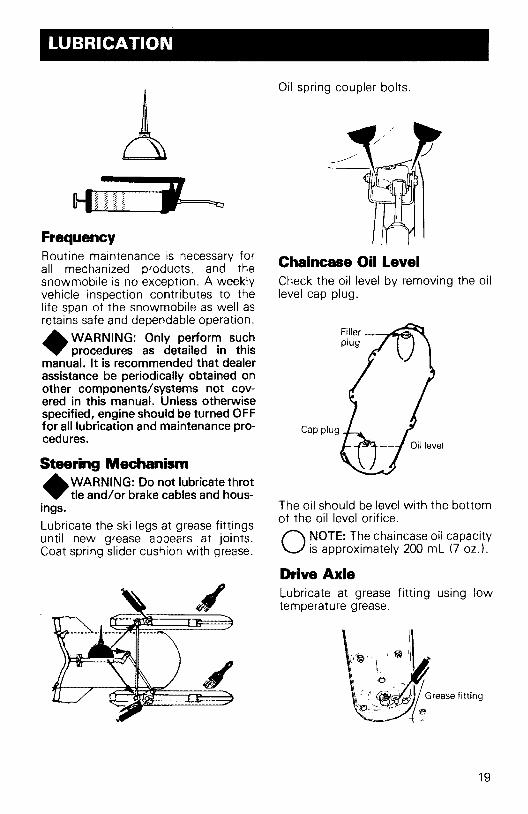
Oil spring coupler bolts.
1\
~" l\'~" ' fi .
L\ ;0
~~~~~Grease fitting
Cap plug
The oil should be level with the bottomof the oil level orifice.
O NOTE: The chaincase oil capacityis approximately 200 mL (7 oz.l.
Drive AxleLubricate at grease fitting using lowtemperature grease.
Chaincase Oil LevelCheck the oil level by removing the oillevel cap plug.
~~Uli ,
FrequencyRoutine maintenance is necessary forall mechanized products, and thesnowmobile is no exception. A weeklyvehicle inspection contributes to thelife span of the snowmobile as well asretains safe and dependable operation.
+WARNING: Only perform suchprocedures as detailed in this
manual. It is recommended that dealerassistance be periodically obtained onother components/systems not covered in this manual. Unless otherwisespecified, engine should be turned OFFfor all lubrication and maintenance procedures.
Steering Mechanism
+WARNING: Do not lubricate throttie and/or brake cables and hous
ings.
Lubricate the ski legs at grease fittingsuntil new grease appears at joints.Coat spring slider cushion with grease.
19

... CAUTION: When lubricating the... drive axle bearing, do not apply
excessive grease to avoid pushing theseal out of its housing.
Check the seal position with finger.
SuspensionLubricate idler wheels at grease fittingsuntil grease appears at joints. Use lowtemperature grease only.
Grease fitti ngs
It is recommended that the steeringsystem and suspension be lubricatedmonthly or every 40 hours of operation. If the vehicle is operated in wetsnow or in severe conditions theseitems should be lubricated more frequently.
20

MAINTENANCE
The following Maintenance Chart indicates regular servicing schedules to beperformed by you or your servicingdealer. If these services are performedas suggested, your snowmobile willgive you many years of low-cost use.
+WARNING: Only perform suchprocedures as detailed in this
manual. It is recommended that dealerassistance be periodically obtained onother components/systems not coveredin this manual. Unless otherwise specified, engine should be turned OFF forall lubrication and maintenance procedures.
E E (1)O'l
0 § m roMAINTENANCE LO a...- (1)
B>~E»- >~EECHART - .... E
~~~ ~~~ro(1)~ CD
gs(1)o (1»08 Q)0(1)0 U(1)oos .... ..:::t ~ .... o 60~N a::ON oeo
Drive belt condition • 22
Brake condition • 24
Brake adjustment • 24Spark plug(s) • 24
Track condition • 25
Track tension and alignment • 25
Suspension condition • 26Suspension adjustment • 26Drive pulley • 27Steering mechanism • 27Steering adjustment • 27Muffler attachment • 28Carburetor adjustment • 28
Fan belt • 28Engine head nuts • 28
Engine mount nuts • 28Headlamp beam aiming • 29General inspection • 29
O N~TE: The ten hour inspection is a very important part of proper service andmaintenance.
21

Drive belt removal andinstallation
WARNING: At the removal or installation of the drive belt be
careful not to burn yourself on the exhaust muffler.
1. Remove the pulley guard.
2. Loosen the countershaft bearing retaining screw and open the bearingcage.
\
LI Retaining}" clip.¥
A
c
Drive Belt ConditionInspect belt for cracks, fraying or abnormal wear (uneven wear, wear onone side, missing cogs, cracked fabric). If abnormal wear is noted, probable cause could be pulley misalignment, excessive R.P.M. with frozentrack, fast starts without warm-up period, burred or rusty sheave, oil on beltor distorted spare belt. Contact yourdealer.
Check the drive belt width. If less than2.7 cm (1 1/16 in), replace the drivebelt.
New Drive BeltWhen installing a new drive belt,break-in period of 25 km (15 miles) isstrongly recommended.
O NOTE: Always store a sparebelt ina mariner to allow its natural shape
to be maintained.
BELT & GUARD REMOVALPulley Guard Removal
+WA RNING: Pulley guard shouldalways be in place when engine is
running.
A. Raise the hood and remove the retaining clip of the rear pin and remove the pin.
B. Pull the guard out of the center retaining bolt.
C. Remove the guard.
22

3. Open the driven pulley by twistingand pushing the sliding half. Hold infully open position.
O NOTE: It may be necessary· toloosen the brake adjustment in
order to easily lift the countershaft.
Slip the belt out from the drive pulley.
Brake disc -~Mi;lllllliI
Brake pads
Brake light [ __switch
To install the drive belt, reverse theprocedure.
~ CAUTION: Once belt is installed,.. be sure to secure the counter
shaft bearing by closing the bearingcage and firmly tightening the retainingscrew.
~
+WARNING: After drive belt installation, always check that the
brake disc is correctly installed between the brake pads and that thebrake is well adjusted. Check braketight operation.
5. Lift the countershaft upward approx. 50 mm (2 ln.) and slip the beltbetween the shaft and the bearingcage to remove completely.
4. Slip the belt over the top edge of thesliding half.
23

Brake pads3 mm (1/8") min.
thickness
Brake ConditionThe brake mechanism on your snowmobile is an essential safety device.Keep this mechanism in proper working condition. Above all, do not operate your snowmobile without an effective brake system.
A. WARNING: Brake pucks less"., than 3 mm (1/S") thick must bereplaced. Replacement must be performed by an authorized dealer.
Brake AdjustmentBrake should apply fully while brakecontrol lever is still 13 mm (1/2") approximative from the handlebar grip.
If adjustment is required, turn thebrake cable adjuster counter-clockwiseuntil the brake disc is hard to turn thenback off the adjuster to approximately1 1/2 turn. Recheck brake operation.
A. WARNING: Whenever the brake"., is readjusted, the brake lightswitch operation must also be checkedand adjusted as needed.
24
Brake Light Switch AdjustmentTo check operation:
Pull the brake lever to hold the pads onthe disc. Check that a light resistanceis felt while rotating the driven pulley.This is the position where the switchshould have lit the brake light.
To adjust:
- Loosen the brake switch lock nut.
- Holding brake lever at the lit posi-tion, unscrew the switch to light onor screw it in to put out the light.
Unscrew tolight
- Tighten the brake switch lock nutand recheck brake light operation.
Spark Plug(s)Disconnect the spark plug wirels) andremove the spark pluqts).
Check the condition of the pluqts).
• A brownish tip reflects ideal conditions. (Correct carburetor, sparkplug heat range; etc.).
• A black insulator tip indicates foulingcaused by: carburetor idle speedmixture and/or high speed mixturetoo rich, incorrect fuel mixture ratiowrong type of spark plug (heatrange) I or excessive idling.

• A light grey insulator tip indicates alean mixture caused by: carburetorhigh speed mixture adjusted toolean, wrong spark plug heat range,incorrect fuel mixture ratio, or aleaking seal or gasket.
... CAUTION: If spark plug condi... tion is not ideal, contact your au
thorized dealer.
Check spark plug gap using a wirefeeler gauge.
Reinstall pluqts) and connect wirets),
Track ConditionLift the rear of the vehicle and supportit off the ground. With the engine off,rotate the track by hand, and inspectcondition. If worn, cut or track fibersare exposed or missing or defective inserts or guides are noted, contact yourdealer.
+WARNING: Do not operate asnowmobile with a cut, torn or
damaged track.
Track Tension and Alignment
Tension:Lift the rear of vehicle and support witha mechanical stand. Allow the slide toextend normally. Check the gap 13 mm(112") between the slider shoe and thebottom inside of the track. If the tracktension is too loose, the track will havea tendency to thump.
... CAUTION: Too much tension... will result in power loss and ex
cessive stresses on suspension components.
If necessary to adjust. Loosen the rearidler wheel retaining screw and the adjuster bolt lock nut; then loosen ortighten the adjuster bolts located onthe inner side of the rear idler wheels. Ifcorrect tension is unattainable. Contact your dealer.
loosen
O NOTE: Track tension and alignment are inter-related. Do not ad
just one without the other.
Alignment:Start the engine and accelerate slightlyso that track turns slowly. Check thatthe track is well centered; equal distance on both sides between edges oftrack guides and slider shoes.
25

•WARNING: Before checkingtrackalignment, ensure that the track
is free of all particles which could bethrown out while track is rotating. Keephands, tools, feet and clothing clear oftrack. Ensure no-one isstanding in closeproximity to the vehicle.
To correct, stop the engine, loosen therear idler wheels retaining screws thenloosen the lock nuts and tighten theadjuster bolt on side where the slidershoe is the furthest to the track insertguides.
Tighten lock nuts and recheck thealignment. Ensure to retighten the idlerwheel retaining screws.
Suspension ConditionVisually inspect all suspension components including slider shoes, springs,wheels, etc ...
O NOTE: During normal driving,snow will act as a lubricant and
coolant for the slider shoes. Extensiveriding on ice or sanded snow, (not tomention dirt, asphalt, etc. never recommended) will create excessive heatbuild-up and cause premature slidershoe wear.
26
Suspension AdjustmentThe suspension is adjustable, the frontadjustment for surface condition, therear for driver's weight.
Adjuster blocks
When the front adjuster blocks are atthe lowest elevation more weight isdistributed on the skis.
Weight on skis
At the highest position the weight istransferred to the track. The rear adjuster blocks should be adjusted to suitthe driver's preference.
..CAUTION: Always turn the left... side adjuster blocks in a clock
wise direction, the right side blocks in acounter-clockwise direction. Left andright adjuster blocks of each adjustment must always be set at the sameelevation.

Drive Pulley (roller squareshaft type)Inspect the Duralon bushing conditionby checking the free-play of the slidinghalf pulley. This is achieved by restraining the inner half and checking if thesliding half moves in the direction ofthe arrows more than 3 mm (1/8"). Ifso, contact your dealer.
Mark referencepoint
on both halves
Maximum free-play3 mm {1/S")
Steering MechanismInspect the steering mechanism fortightness of components (steeringarms,tie rods, ball joints, spring couplerbolts, etc.l. If necessary, replace or retighten.
Torque steering arm bolts to 42 N-m(31 tt-Ibs).
Check the condition of the skis and theski runners. Replace if more than halfworn.
Steering AdjustmentSkis should have a toe out of 3 mm(1/8"). To check, measure the distancebetween each ski at the front and rearof the leaf springs. The front distanceshould be 3 mm (1/8") more than therear when the handlebar is horizontal.
IMPORTANT: Close the front of theskis manually to eliminate all slack fromthe steering mechanism.
If adjustment is required:
Loosen the lock nuts of the longer tierod. Turn the tie rod manually until theskis are properly aligned. Firmly retighten the lock nuts.
•3 mm 1118")toe out
t
The handlebar should also be horizontal when the skis are pointed towardthe front.
To adjust:Loosen the lock nuts of the shorter tierod. Turn the tie rod manually until thehandlebar is horizontal. Retighten thelock nuts firmly.
+WARNING: The ball joint socketmust run parallel with the steer
ing arm. The steering arm must be restrained when tightening the tie rodend lock nuts.
27

Muffler AttachmentThe engine/muffler attaching parts arevital toward efficient muffler function.Check all attachments. Replace thesprings and/or tighten if necessary.
Carburetor Adjustment... CAUTION: Never operate your.. snowmobile with the air intake
silencer disconnected. Serious enginedamage will occur if this notice is disregarded.
At Air Screw AdjustmentCompletely close the air screw (until aslight reseating resistance is felt) thenback off screw as specified p.
BJ Idle Speed Adjustment
Turn the idle speed screw clockwiseuntil it contacts the throttle slide thencontinue turning two (2) additionalturns. This will provide a preliminaryidle speed setting. Start the engine andallow it to warm then adjust the idlespeed as per specifications by turningthe idle speed screw clockwise or counter-clockwise.
... CAUTION: Do not attempt to set.. the idle speed by using the air
screw. Severe engine damage can occur. If idle speed is unattainable contact your authorized dealer.
28
Fan BeltInspect belt for cracks. uneven wear,etc. Check fan belt tension, 6 mm(1/4
11
) free-play should exist when deflection is correct.
If belt seems damaged or if tension isincorrect, contact your dealer immediately .
....WARNING: If fan protector is re~moved, always reinstall after servicing.
Engine Head NutsWith the ENGINE COLD, check thatthe engine head nuts are tight andequally torqued to 22 N-m (16 ft-lbs).
Following sequence above shown, torque engine head nuts twice.
IMPORTANT: The engine head nut torque should be checked after the first 5hours of operation.
Engine Mount NutsCheck the engine mount nuts for tightness. Retighten if necessary.

Headlamp Beam AimingThe angle of the headlamp beam hasbeen pre-adjusted prior to delivery.Should you wish re-adjustment, placethe vehicle on a flat surface 7.6 m (25'lfrom a wallar screen.
Headlamp Bulb ReplacementIf the headlamp bulb is burnt, tilt hood,unplug the connector from the headlamp. Remove the rubber boot and unfasten bulb retainer clips. Detach thebulb and replace.
TOPVIEW
SIDEVIEW Ground
~(/
, 0~
With the suspension correctly adjusted,the rider seated on the vehicle and thehigh beam ON check that the center ofhigh intensity zone of high beam is 50mm (2") below horizontal line of headlamp height.
Center lineintensity zone
To adjust, remove the four caps, turnupper or lower adjusting screws to obtain desired beam position.
Taillight Bulb ReplacementIf taillight bulb is burnt, expose thebulb by removing the red plastic lens.To remove, unscrew the two (2) Phillips head screws.
+WARNING: Always check lightoperation after bulb replacement.
General InspectionCheck the electrical wiring and components, retighten loose connections.Check for stripped wires or damagedinsulation. Thoroughly inspect the vehicle and tighten loose bolts, nuts andlinkage. Inspect skis and ski runners forwear.
29

STORAGE
It is during summer, or when a vehicleis not in use for any length of time thatproper storage is a necessity. Storageof the snowmobile during long periodof inactivity consists of checking andreplacing missing, broken or wornparts, proper lubrication and treatmentto insure that parts do not becomerusted; cleaning items such as carburetor of oil mixtures, to prevent gumvarnish formation within the carburetor; and in general, preparing the vehicle so that when the time comes to usethe snowmobile again it will start andbe in top condition .
•WARNING: Only perform suchprocedures as detailed in this
manual. It is recommended that dealerassistance be periodicallv obtained onother components/systems not covered in this manual. Unless otherwisespecified, engine should be turned OFFfor all lubrication and maintenance procedures.
TrackInspect the track for wear, cuts, missing track guides and broken rods.Make any necessary replacement.
•WARNING: Do not operate asnowmobile with a cut, torn or
damage track.
Lift the rear of vehicle until track isclear of the ground then support with abrace or trestle. The snowmobile shouldbe stored in such a way that the trackdoes not stay in contact with the cementfloor or bare ground.
O NOTE: The track should be rotated periodically, (every 40 days).
Do not release track tension.
... CAUTION: To prevent track dam.... age, temperature in the storage
area must not exceed 38°C (100°F).
SuspensionRemove any dirt or rust. Grease idlerwheelsat grease fittings. Wipe off surplus. Replace worn slider shoes.
30
SkisWash or brush all dirt or rust accumulation from the skis and springs. Greasethe ski legs at the grease fittings.Check the condition of the skis, skirunners and leaf springs. Replace ifworn more than half.
Skirunne~
ControlsLubricate the steering mechanism. Inspect all components for tightness,(spring coupler bolts, steering armlocking bolts, tie rods, ball joints, etc.I.Tighten if necessarv, Oil metal movingjoints of the brake mechanism.
+W A RNING: Do not lubricate thethrottle and/or brake cables and
housings. Avoid getting oil on the brakepads.
Coat all electrical connections andswitches with a greaseless metal protector. If unavailable, use petroleum jelly.
ChaincaseDrain the chaincase and refill to properlevel, using fresh chaincase oil. Todrain, remove the chaincase cover.
Drive PulleyThe drive pulley should be cleaned andinspected.
•WARNING: The lubrication and/or inspection of the drive pulley
should be performed only by an authorized dealer.
Fuel Tank and Carburetorls)Remove the cap then using a syphon,remove the gasoline from tank.

+WARNING: Gasoline is flammable and explosive under certain
conditions. Always manipulate in awell ventilated area. Do not smoke orallow open flames or sparks in the vicinity.Carburetor(s) must be dried out completely to prevent gum formation during the storage period.
Once the fuel tank is emptied, removethe float chamber drain pluqts) fromcarburetorts). Drain carburetorts) andreinstall pluqts).
Connect fuel lines. Replace if necessary.
Cylinder LubricationEngine internal parts must be lubricatedto protect cylinder walls from possiblerust formation during the storage period.
Use storage oil (8 oz) PIN 4139048 00.Protection will last for the normal storage period.
Procedure:
- Insert plastic tube in spray headnozzle.
- Remove air silencer.
- Run engine at idle speed.
- Spray storage oil directly into carbu-retor until engine stalls .
... CAUTION: Only perform this proY cedure in a well ventilated area.
If adequate ventilation is not available.
- Remove spark plugs and spray approximately 1 ounce of storage oil ineach spark plug hole and in eachcarburetor.
~ CAUTION: Ensurecut-out switch.. and/or ignition key is in OFF posi
tion.
- Crank engine over several times.
- Reinstall plugs.
Do not run engine during storage period.
31

ChassisClean the vehicle thoroughly I removingall dirt and grease accumulation.
~ CAUTION: Plastic alloy compoY nents such as fuel tank, controls,
windshield, etc., can be cleaned usingmild detergents or isopropyl alcohol.Do not use strong soaps, degreasingsolvents, abrasive cleaners, paint thinners, etc.
Clean the frame. For the aluminumportion use only 1/ Aluminum cleaner"and follow instructions on the container.
Touch up all metal spots where painthas been scratched off. Spray all baremetal parts with metal protector. Waxthe cab for better protection .
.., CAUTION: Cover the snowmobile... with an opaque tarpaulin. This will
prevent the sun rays or grime from affecting the plastic components and vehicle finish.
General InspectionCheck the electrical wiring and components, retighten loose connections.Check for stripped wires or damagedinsulation.
Thoroughly inspect the vehicle andtighten loose bolts, nuts and linkage.
O NOTE: Leave the drive belt offthe pulleys for the entire storage
period.
32
PRE..SEASON PREPARATION
To simplify the pre-season preparationwe have drawn up a small chart. Thechart indicates servicing points to beperformed by you and your servicingdealer. If these services are performedas suggested, your vehicle will giveyou many hours of fun and low costuse.
IMPORTANT: Observe all Warningsand Cautions mentioned throughoutthis manual which are pertinent to theitem being checked. When componentconditions seem less than satisfactory,replace with genuine Bombardier partsor suitable equivalents.

TO BE PERFORMED BY DEALER •PRE-SEASON PREPARATION CHARTTO BE PERFORMED BY OWNER 0
Change spark plugs* 0
Check chaincase oil level 0
On vehicle equipped with fuel filter cartridge, replace cartridge 0
Check track tension and alignment 0
Lubricate suspension 0
Inspect drive belt and install 0
Check throttle cable for damage and free operation 0
Check steering alignment and ski runner condition 0
Inspect seals for possible cuts or leaks 0
Check electrical wiring (broken wire, damaged insulation) 0
Inspect condition of starting rope 0
Check tightness of all bolts, nuts and linkage 0
Refill gas tank 0
Inspect brake condition and operation •Set engine timing •Check pulleys, verify components and clean. Lubricate. .-Adjust carburetor(s) •
*0 NOTE: Before installing new spark plugs, it is suggested to burn the excess storage oil by starting the engine, using the old spark plugs .
• CAUTION: Only perform this procedure in a well ventilated area.
33

O NOTE: The possible causes have been listed in an order of frequency.Therefore, items should be checked out in the same order as mentionedI
in the trouble shooting guide.
SYMPTOMS POSSIBLE CAUSES WHAT TO DO
Engine turns over but 1. No fuel to the engine Check the tank level. Check forpossible cloggingfails to start or starts of fuel line, item 4.with difficulty
2. Flooded engine Remove wetspark plugs, turn ignition to OFFand crank engine several times. Install cleandry spark plugs. Start engine following usualstarting procedure. If engine continues toflood, see your dealer.
3. Spark plugl ignition Check for fouled or defective spark plug. Dis-connect spark plug wire, unscrew plug and re-move from cylinder head. Reconnect wire andground exposed plug on engine cowl, beingcanfuI to bald awaytram IpII'k pq hale.Follow engine starting procedure and checkfor spark. If nosparks appear, replace sparkplug. If trouble persists, contact your dealer.
4. Clogged fuel line (water or Remove and clean the fuel filter. Change filterdirt) cartridge if necessary. Check condition and
connections offuel lines. Check the cleanlinessof fuel tank.
5. Carburetor Contact your dealer for repair.
6. Too much oil in fuel Contact your dealer.
7. Engine timing Engine timing may be incorrect or out of ad-justment. Contact your dealer.
8. Engine compression Running with a lean fuel mixture may produceexcessive engine wear resulting inpoor enginecompression. If this occurs, contact yourdealer at once.
Engine will not turn 1- Seized engine In the case of a seized engine contact yourmanually dealer.
34

SYMPTOMS POSSIBLE CAUSES WHAT TO DO
Engine lacks accelera- 1. Fouled or defective spark Check item 3 of "Engine turns over but failstion or power plug to start or starts with difficulty"
2. Clogged fuel line (water or Check fuel line condition. ISee item 4 of "En-dirt) gine turns over but fails to start or starts
with difficulty"!.
3. Carburetors Contact your dealer.
4. Ignition First check item 3 of "Engine turns over butfails to start or starts with difficulty".If the ignition system still seems faulty,contact your dealer.
--; Engine If unable to locate specific symptoms, contactyour dealer.
Engine continually 1. Faulty spark plug Check item 3 of "Engine turns over but fails tobackfires start or starts with difficulty".
2. Overheating Carburetor set too lean. Contact your dealer.
3. Engine timing incorrectly set Contact your dealer.
Snowmobile cannot 1. Drive Belt Check for damaged or worn drive belt. Re·reach full speed place if necessary.
2. Incorrect track adjustment Check track tension and alignment. Readjustto specifications. ISee Maintenance Sectionl
3. Engine Check item 1 to 5 of "Engine lacks acceler-anon or power".
4. Pulley misaligned Contact your dealer.
35

TOOLS
As standard equipment each newsnowmobile is supplied with a basictool kit such as screwdriver, wrenches,emergency starter rope, etc ...
Standard Tools
A
~===~g
cE
D
A. Screwdriver
B. Socket 21/26 mm
C. Socket 10/13 mm
D. Socket handle
E. Angular wrench 10/13 mm
F. Starter rope
G. Emergency starter rope handle
36
G

38.1 cm (15") 38.1 cm (15")315 cm (124") 353 em (139")
13 mm (t/2") gap between slide shoe and bottom inside oftrack.
Equal distance between edges of track guides and slidershoes.
14/35 14/35
SPECIFICATIONS
IENGINENo. of cylindersBoreStrokeDisplacementCompression ratio(corrected)Maximum R.P.M.Carburetor typeCarburetor adjustment:
air screw- idle speed
Torque:engine head nutscrankcase nuts
magneto ring nut- fan nut- crankcase engine
support nuts- exhaust manifold bolts
CHASSISOverall lengthOverall widthOverall heightSki stance(center to center)Ski alignment (toe out)Torque:- steering arm/ski leg
boltsteering column/handlebar
Dry weightBearing areaGround pressure
POWER TRAINTrack:- width
length- tension
alignment
Standard gear ratioDrive belt:
numberMax. width
- Min. widthChaincase oil
NORDIK
262 mm (2.44")61 mm (2.40")368.3 em3 (22.47 in3)6.9:1
7500VM34
1 112 turn1800-2000 RPM
22 N.m (16 ft-lbslM6 9 N·m (6 tt-los)M822 N.m (16 ft-Ibsl85 N.m (62 ft-Ibsl65 N.m (48 ft-Ibsl38 N.m (27 ft-lbsl
22 N.m (16 ft-lbs]
274 cm (1073/4")90.5 cm (35 1/2")130.8 em (51 1/2")76.2 cm(30")
3.0 mm (1IS")
43 N·m (32 ft-lbs]
26 N.m (19 ft-lbsl
172 kg (380 Ibs)6865 cm2 (1064 in2)2.46 kPa (.357 PSI)
4143758 0033.3 mm (1 5/16")30.1 mm (1 3/16")200 mL (7 oz)
I SKANDIC
262 mm (2.44")61 mm (2.40")368.3 em3 (22.47 in316.55:1
75002 x VM 34
1 1/2 turn1800-2000 RPM
22 N.m (16 ft-lbslM6 9 N.m (6 ft-lbslM822 N.m (16ft-lbs)85 N.m (62 ft-lbs)65 N.m (48 ft-lbs)38 N.m (27 ft-Ibs)
22 N.m (16 ft-lbs)
289.5 em (114")96.5 cm (38")108 cm (421/2")82 cm (32 114")
3.0 mm (1/8")
43 N·m (32 ft-lbsl
26 N.m (19 ft-Ibs)
193 kg (426 Ibs)7579 cm2 (1175 in2)2.50 kPa (.363 PSI)
4143758 0033.3 mm (1 5J16")30.1 mm (1 3/16")200 mL (7 oz)
37

ELECTRICALLighting system (output)!Bulb:- head/amp- tail/stop- speedometer
tachometerFuse:- tachometerSpark plug- type
gapIgnition timing:- timing mark (B.T.D.C.)
stroboscopic timing
12 volts/160 watts
so/sow5/21 W5W5W (optional)
0.1 A
NGK BR-BES.4 mm (.016")
2.52 mm ('099") (20°)6000 RPM
112 volts/l60 watts
so/sow5/21 W5W5W (optional)
0.1 A
NGK BR-8ES.4 mm ('016")
2.52 mm (.099,i) (20°)6000 RPM
13 mm (1/2") minimum distance from handlebar grip whenfully applied.
FUELGas typeFuel tank capacity
- SIImp.
- U.S.Oil type
BRAKETypeLining minimumthickness
I Control lever adjustment
28.4litres6.25 gals7.8 gals
Disk3 mm (1/B")
Regular leaded or unleaded
2B.4litres6.25 gals7.8 gals
Bombardier snowmobile oil
Disk3 mm (1/S")
Bombardier Inc. reserves the right to make changes in design and specifications and/or to make additions to, or improvements in its product without imposing any obligation upon itself to install them onits products previously manufactured.
38

x.u.SWITCH
'llTlON$WITCH
NORDIK 1982SKANDIC 1982
CD LIGHTING COIL0AMPLIFIERG)CHARGING COILSo HEADLAMP (60/60 W)@LAMP(5W)
® TAILLAMP (5/21 W)(j) FUSE (0.1 Al
® IGNITION COIL
VI-;
1EUROPEI
r---------J.-..=.;..;.;..-f6 P;":";"'---+4' 't1r-------,l,......\bf---{ 7.-= ---1
(STANDARD!
tilg~I
COLOUR CODE
BK - BLACK GN - GREENWH - WHITE GY - GREYRD RED VI VIOLETBL - BLUE OR - ORANGEYL - YELLOW BR - BROWN
•WARNING: Ensure all terminalsare properly crimped on the wires
and all connector housings are properly fastened.
W<0

51* METRIC INFORMATION GUIDE
BASE UNITS
DESCRIPTION UNIT SYMBOL
length meter m
mass kilogram kgliquid liter Ltemperature celsius °Cpressure kilopascal kPatorque Newton meter N.m
speed kilometer per hour km/h
PREFIXES
PREFIX SYMBOL MEANING VALUE
kilo k one thousand 1,000centi c one hundredth of a 0.01milli m one thousandth of a 0.001
*THE INTERNATIONAL SYSTEM OF UNITS (SYSTEME INTERNATIONAL)
ABREVIATES "SI" IN ALL LANGUAGES.
40
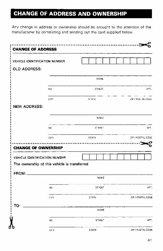
CHANGE OF ADDRESS AND OWNERSHIP
Any change in address or ownership should be brought to the attention of themanufacturer by completing and sending out the card supplied below.
: ~
: CHANGE OF ADDRESS
·: VEHICLE IDENTIFICATION NUMBER
: OLD ADDRESS:
NAME
NO STREET APT.
CITY STATE ZIP I POSTAL CODE
APT.
APT.
ZIP I POSTAL CODE
ZIP I POSTAL CODE
NAME
NAME
STREET
STREET
STATE
STATE
CITY
NO
CITY
NO
: NEW ADDRESS:
··········:..........................................•.......... ... ... .... ... .... .. ..~: CHANGE OF OWNERSHIP:-------------------------------: VEHICLE IDENTIFICATION NUMBER
: The ownership of this vehicle is transferred
·: FROM: _
··········• TO:
NAME
NO
CITY
STREET
STATE
APT.
ZIP I POSTAL CODE
41

BOMBARDIER INC.ATT.: WARRANTY DEPARTMENTVALCQURT,QUEBECCANADA, JOE 2LO
BOMBARDIER INC.ATT.: WARRANTY DEPARTMENTVALCQURT,QUEBECCANADA, JOE 2LO
.................................................................................···························
··.................................................................................························
42