1925-Practical Astronomy (3rd Edition)
314
-
Upload
paullvalery -
Category
Documents
-
view
50 -
download
7
description
astronomy
Transcript of 1925-Practical Astronomy (3rd Edition)


TIGHT BINDING BOOK

uj< OU=5 CQ
o
160113>m

0$MANIA UNIVERSITY LIBRARY


OSMANIA UNIVERSITY LIBRARY
Author
This book should be returned on or befo/he daternnrt^ri Kl^,., > *last marked below.


Observation on Polaris for AzimuthFrontispiece

PRACTICAL ASTRONOMY
A TEXTBOOK FOR ENGINEERING SCHOOLSAND
A MANUAL OF FIELD METHODS
BY
GEORGE L. HQSMERAssociate Professor of Geodesy, Massachusetts Institute of Technology
THIRD EDITION
NEW YORK *
JOHN WILEY & SONS, INC.
LONDON: CHAPMAN & HALL, LIMITED
TA-5C1

CCflPYRIGHT, 1910, 1917 AND 1925
BY
GEORGE L. HOSMER
PREFACE
THE purpose of this volume is to furnish a text in Practical
Astronomy especially adapted to the needs of civil-engineering
students who can devote but little time to the subject, and who
are not likely to take up advanced study of Astronomy. The
text deals chiefly with the class of observations which can be
made with surveying t instruments, the methods applicable to
astronomical and geodetic instruments being treated b$t briefly.
It has been the author's intention to produce a book%hich is
intermediate between the text-book written for the student of
Astronomy or Geodesy and the short chapter on the subject
generally given in text-books on Surveying. The subject has
therefore been treated from the standpoint of the engineer, who
is interested chiefly in obtaining results, and those refinements
have been omitted which are beyond the requirements of the
work which can be performed with the engineer's transit. This
has led to the introduction of some rather crude mathematical
processes, but it is hoped that these are presented in such a wayas to aid the student in gaining a clearer conception of the prob-
lem without conveying wrong notions as to when such short-cut
methods can properly be applied. The elementary principles
have been treated rather elaborately but with a view to makingthese principles clear rather than to the introduction of refiner
ments. Much space has been devoted to the Measurement of
Time because this subject seems to cause the student more
difficulty thar \y other branch of Practical Astronomy. The
attempt has Iv{ J made to arrange the text so that it will be a
convenient reference book for the engineer who is doing field
work.
For convenience in arranging a shorter course those subjects
ill
iv PREFACE
which are most elementary are printed in large type. The mat-
ter printed in smaller type may be included in a longer course
and will be found convenient for reference in field practice, par-
ticularly that contained in Chapters X to XIII.
The author desires to acknowledge his indebtedness to those
who have assisted in the preparation of this book, especially to
Professor A. G. Robbins and Mr. J. W. Howard of the Massa-
chusetts Institute of Technology and to Mr. F. C. Starr of the
George Washington University for valuable suggestions and crit-
icisms of the manuscript.
G. L. H.
BOSTON, June, 1910.
PREFACE TO THE THIRD EDITION
THE adoption of Civil Time in the American Ephemeris and
Nautical Almanac in place of Astronomical Time (in effect in
1925) necessitated a complete revision of this book. Advantagehas been taken of this opportunity to introduce several improve-
ments, among which may be mentioned: the change of the no-
tation to agree with that now in use in the principal textbooks
and government publications, a revision of the chapter on the
different kinds of time, simpler proofs of the refraction and
parallax formulae, the extension of the article on interpolation
to include two and three variables, the discussion of errors bymeans of differentiation of the trigonometric formulae, the in-
troduction of valuable material from Serial 166, U. S. Coast
and Geodetic Survey, a table of convergence of the meridians,
and several new illustrations. In the chapter on Nautical As-
tronomy, which has been re-written, tfee method bf Marcq Saint-
Hilaire and the new tables (H. O. 201 and 203) for laying downSumner lines are briefly explained. An appendix on Spherical
Trigonometry is added for convenience of reference. The size

PREFACE V
of the book has been reduced to make it convenient for field use.
This has been done without reducing the size of the type.
In this book an attempt has been made to emphasize the
great importance to the engineer of using the true meridian and
true azimuth as the basis for all kinds of surveys; the chapter
on Observations for Azimuth is therefore the most important
one from the engineering standpoint. In this new edition the
chapter has been enlarged by the addition of tables, illustrative
examples and methods of observing.
Thanks are due to Messrs. C. L. Berger & Sons for the use
of electrotypes, and to Professor Owen B. French of George
Washington University (formerly of the U. S. Coast and Geo-
detic Survey) for valuable suggestions and criticisms. The
author desires to thank those who have sent notices of errors
discovered in the book and asks their continued cooperation.
G. L. H.
CAMBRIDGE, MASS., June, 1924.


CONTENTS
CHAPTER I
THE CELESTIAL SPHERE REAL AND APPARENT MOTIONS
CHAPTER II
DEFINITIONS POINTS AND CIRCLES OP REFERENCE
10. Definitions ................................................... 14
Vertical Line Zenith Nadir Horizon Vertical Circles
Almucantars Poles Equator Hour Circles Par-
allels of Declination Meridian Prime Vertical Eclip-
tic Equinoxes Solstices.
CHAPTER III
SYSTEMS OF COORDINATES ON THE SPHERE
11. Spherical Coordinates .......................................... 18
12. The Horizon System ........................................... 19
13. The Equator Systems ......................................... 19
15. Coordinates of the Observer .................................. '. . 22
16. Relation between the Two Systems of Coordinates ................ 23
CHAPTER IV
RELATION BETWEEN COORDINATES
17. Relation between Altitude of Pole and Latitude of Observer ........ 27
18. Relation between Latitude of Observer and the Declination and Alti-
tude of a Point on the Meridian ............................... 30vii
Viii CONTENTS
ART. PAGE
19. The Astronomical Triangle ..................................... 31
20. Relation between Right Ascension and Hour Angle ................ 36
CHAPTER V
MEASUREMENT OF TIME
21. The Earth's Rotation .......................................... 4<
22. Transit or Culmination ........................................ 4c
23. Sidereal Day .................................................. 40
24. Sidereal Time ................................................. 41
25. Solar Day .................................................... 41
26. Solar Time ................................................ 41
27. Equation of Time ............................................ 42
28. Conversion of Mean Time into Apparent Time and vice versa ........ 45
29. Astronomical Time Civil Time ................................ 46
30. Relation between Longitude and Time .......................... 46
31. Relation between Hours and Degrees ............................ 49
32. Standard Time ................................................ 50
33. Relation between Sidereal Time, Right Ascension and Hour Angle of
any Point at a Given Instant ................................. 52
34. Star on the Meridian .......................................... 53
35. Mean Solar and Sidereal Intervals of Time ....................... 54
36. Approximate Corrections ...................................... 56
37. Relation between Sidereal and Mean Time at any Instant. ......... 57
38. The Date Line ................... ........................... 61
39. The Calendar ................................................ 62
CHAPTER VI
THE AMERICAN EPHEMERIS AND NAUTICAL ALMANAC STAR
CATALOGUES INTERPOLATION
40. The Ephemeris ................................................ 6^
41. Star Catalogues ............................................... 6*
42. Interpolation ................................................. 7,
43. Double Interpolation .......................................... 7;
CHAPTER VII
THE EARTH'S^ FIGURE CORRECTIONS TO OBSERVED ALTITUDES
44. The Earth's Figure. . .......................................... 7
45. The Parallax Correction ........................................ 8.
46. The Refraction Correction ............"
.......................... 84
47. Semidiameters ............................................... 87
48. Dip of the Sea Horizon ........................................ 88
49. Sequence of Corrections. ... .................................... 89
CONTENTS IX
CHAPTER VIII
DESCRIPTION OF INSTRUMENTS OBSERVINGRT. PAGE
50. The Engineer's Transit 91
51. Elimination of Errors 92
52. Attachments to the Engineer's Transit Reflector 95
-53. Prismatic Eyepiece 96
54. Sun Glass'
96
55. The Portable Astronomical Transit 96
56. The Sextant 100
57. Artificial Horizon 103
58. Chronometer 104
/ 59. Chronograph 105
60. The Zenith Telescope 105
61. Suggestions about Observing 107
62. Errors in Horizontal Angles 108
CHAPTER IX
i THE CONSTELLATIONS
63. The Constellations no64. Method of Naming Stars no65. Magnitudes 111
66. Constellations near the Pole nr67. Constellations near the Equator 112
68. The Planets 114
CHAPTER X
OBSERVATIONS FOR LATITUDE
"69. Latitude by a Circumpolar Star at Culmination 115
70. Latitude by Altitude of the Sun at Noon 117
71. Latitude by the Meridian Altitude of a Southern Star 119
72. Altitudes Near the Meridian 120
73. Latitude by Altitude of Polaris when the Time is Known 122
74. Precise Latitudes Harrebow-Talcott Method 125
CHAPTER XI
OBSERVATIONS FOR DETERMINING THE TIME
75. Observations for Local Time 127
76. Time by Transit of a Star 127
77. Observations with Astronomical Transit 130
X . CONTENTS
ART. PAGE78. Selecting Stars for Transit Observations 131
79. Time by Transit of the Sun*
13480. Time by Altitude of the Sun 13481. Time by Altitude of a Star 137
82. Effect of Errors in Altitude and Latitude 139
83. Time by Transit of Star over Vertical Circle through Polaris 140
84. Time by Equal Altitudes of a Star v 143
85. Time by Two Stars at Equal Altitudes 143
88. Rating a Watch by Transit of a Star over a Range 151
89. Time Service 151
CHAPTER XII
OBSERVATIONS FOR LONGITUDE
90. Methods of Measuring Longitude 154
91. Longitude by Transportation of Timepiece 154
92. Longitude by the Electric Telegraph 155
93. Longitude by Time Signals 156
94. Longitude by Transit of the Moon 157
CHAPTER XIII
OBSERVATIONS FOR AZIMUTH
95. Determination of Azimuth 161
96. Azimuth Mark : 161
97. Azimuth by Polaris at Elongation .* 162
98. Observations near Elongation 166
99. Azimuth by Elongations in the Southern Hemisphere 166
100. Azimuth by an Altitude of the Sun 167
101. Observations in the Southern Hemisphere 176
102. Most Favorable Conditions for Accuracy 178
103. Azimuth by an Altitude of a Star near the Prime Vertical 181
104. Azimuth Observation on a Circumpolar Star at any Hour Angle 181
105. The Curvature Correction 184
106. The Level Correction 184
107. Diurnal Aberration 185
108. Observations and Computations 185
109. Meridian by Polaris at Culmination 188
ito. Azimuth by Equal Altitudes of a Star 195
ill* Observation for Meridian by Equal Altitudes of the Sun in the Fore-
noon and in the Afternoon 196
112. Azimuth of Sun near -Noon 197
113, Meridian by the Sun at the Instant of Noon 199
CONTENTS xi
ART. PAGE
114. Approximate Azimuth of Polaris when the Time is Known 200
115. Azimuth from Horizontal Angle between Polaris and ft Ursw Minoris . . 205
116. Convergence of the Meridians 206
CHAPTER XIV
NAUTICAL ASTRONOMY
117. Observations at Sea 211
Determination of Latitude at Sea:
> 118. Latitude by Noon Altitude of the Sun 211
119. Latitude by Ex-Meridian Altitudes 212
Determination of Longitude at Sea:
1 20. By the Greenwich Time and the Sun's Altitude 213
Determination of Azimuth at Sea:
121. Azimuth of the Sun at a Given Time 214
Determination of Position by Means of Sumner Lines:
122. Sumner's Method of Determining a Ship's Position 215
123. Position by Computation 219
124. Method of Marcq St. Hilaire 222
125. Altitude and Azimuth Tables Plotting Charts 223
TABLES
I. MEAN REFRACTION 226
II. CONVERSION OF SIDEREAL INTO SOLAR TIME 227
III. CONVERSION OF SOLAR INTO SIDEREAL TIME 228
IV. (A) SUN'S PARALLAX (B) SUN'S SEMIDLAMETER (C) DIP OF
HORIZON 229
V. TIMES OF CULMINATION AND ELONGATION OF POLARIS 230
VI. FOR REDUCING TO ELONGATION OBSERVATIONS MADE NEAR ELON-
GATION 231
VII. CONVERGENCE IN SECONDS FOR EACH 1000 FEET ON THE PARALLEL. . 232
VIII. CORRECTION FOR PARALLAX AND REFRACTION TO BE SUBTRACTED
FROM OBSERVED ALTITUDE OF THE SUN 233
IX. LATITUDE FROM CIRCUM-MERIDIAN ALTITUDES OF THE SUN 234
., 2 sin2 k TX. VALUES OF m =
: rr 235sin i
FORMS FOR RECORD Observations on Sun for Azimuth 240
GREEK ALPHABET 242
ABBREVIATIONS USED IN THIS BOOK 243
APPENDIX A The Tides 244
APPENDIX B Spherical Trigonometry 255


PRACTICAL ASTRONOMY
CHAPTER I
THE CELESTIAL SPHERE REAL AND APPARENTMOTIONS
i* Practical Astronomy.
Practical Astronomy treats of the theory and use of astro-
nomical instruments and the methods of computing the results
obtained by observation. The part of the subject which is of
especial importance to the surveyor is that which deals with the
methods of locating points on the earth's surface and of ori-
enting the lines of a survey, and includes the determination of
(i) latitude, (2) time, (3) longitude, and (4) azimuth. In solving
these problems the observer makes measurements of the direc-
tions of the sun, moon, stars, and other heavenly bodies; he is
not concerned with the distances of these objects, with their
actual motions in space, nor with their physical characteristics,
but simply regards them as a number of visible objects of known
positions from which he can make his measurements.
2. The Celestial Sphere.
Since it is only the directions of these objects that are required
in practical astronomy, it is found convenient to regard all
heavenly bodies as being situated on the surface of a sphere
whose radius is infinite and whose centre is at the eye of the
observer. The apparent position of any object on the sphere is
found by imagining a line drawn from the eye to the object, and
prolonging it until it pierces the sphere. For example, the
apparent position of Si on the sphere (Fig. i) is at Si, which is
supposed to be at an infinite distance from C; the position of
82 is S%, etc. By means of this imaginary sphere all problems
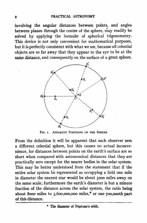
2 PRACTICAL ASTRONOMY
involving the angular distances between points, and angles
between planes through the centre of the sphere, may readily be
solved by applying the formulae of spherical trigonometry.
This device is not only convenient for mathematical purposes,
but it is perfectly consistent with what we see, because all celestial
objects are so far away that they appear to the eye to be at the
same distance, and consequently on the surface of a great sphere.
FIG. i. APPARENT POSITIONS ON THE SPHERE
From the definition it will be apparent that each observer sees
a different celestial sphere, but this causes no actual inconve-
nience, for distances between points on the earth's surface are so
short when compared with astronomical distances that they are
practically zero except for the nearer bodies in the solar system.
This may be better understood from the statement that if the
entire solar system be represented as occupying a field one mile
in diameter the nearest star would be about 5000 miles away on
the same scale; furthermore the earth's diameter is but a minute
fraction of the distance across the solar system, the ratio being
about 8000 miles to 5,600,000,000 miles,* or one 7oo,oooth part
of this distance.
* The diameter of Neptune's orbit.

THE CELESTIAL SPHERE 3
Since the radius of the celestial sphere is infinite, all of the
lines in a system of parallels will pierce the sphere in the same
point, and parallel planes at any finite distance apart will cut
the sphere in the same great circle. This must be kept constantly
in mind when representing the sphere by means of a sketch, in
which minute errors will necessarily appear to be very large.
The student should become accustomed to thinking of the
appearance of the sphere both from the inside and from an out-
side point of view. It is usually easier to understand the spheri-
cal problems by studying a small globe, but when celestial
objects are actually observed they are necessarily seen from a
point inside the sphere.
3. Apparent Motion of the Celestial Sphere.
*If a person watches the stars for several hours he 'will see that
they appear to rise in the east and to set in the west, and that
their paths are arcs of circles. By facing to the north (in the
northern hemisphere) it will be found that the circles are smaller
and all appear to be concentric about a certain point in the skycalled the pole ;
if a star were exactly at this point it would have
no apparent motion. In other words, the whole celestial sphere
appears to be rotating about an axis. This apparent rotation
is found to be due simply to the actual rotation of the earth
about its axis (from west to east) in the opposite direction to
that in which the stars appear to move.*
4. Motions of the Planets.
If an observer were to view the solar system from a point far
outside, looking from the north toward the south, he would see
that all of the planets (including the earth) revolve about the
sun in elliptical orbits which are nearly circular, the direction
of the motion being counter-clockwise or left-handed rotation.
* This apparent rotation may be easily demonstrated by taking a photo-
graph of the stars near the pole, exposing the plate for several hours. Theresult is a series of concentric arcs all subtending the same angle. If the
camera is pointed southward and high enough to photograph stars near the
equator the star trails appear as straight lines.
4 PRACTICAL ASTRONOMY
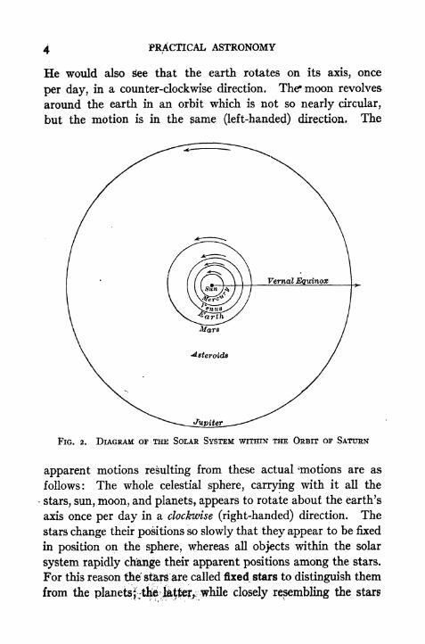
He would also See that the earth rotates on its axis, once
per day, in a counter-clockwise direction. The* moon revolves
around the earth in an orbit which is not so nearly circular,
but the motion is in the game (left-handed) direction, The
FIG. 2. DIAGRAM OF THE SOLAR SYSTEM WITHIN THE ORBIT OP SATURN
apparent motions resulting from these actual ^motions are as
follows: The whole celestial sphere, carrying with it all the
-
stars, sun, moon, and planets, appears to rotate about the earth's
axis once per day in a clockwise (right-handed) direction. The
stars change their positions so slowly that they appear to be fixed
in position on the sphere, whereas all objects within the solar
system rapidly change their apparent positions among the stars.
For this reason tie stars are called fixed stars to distinguish them
from the planetsj^t^ closely resembling the stars

THE CELESTIAL SPHERE 5
in appearance, are really of an entirely different character. Thesun appears to move slowly eastward among the stars at the rate
of about i per day, and to make one revolution around the earth
FIG. 3a. SUN'S APPARENT POSITION AT GREENWICH NOON ON MAY 22, 23,AND 24, 1910
10
Y IV III
FIG. 3b. MOON'S APPARENT POSITION AT 14^ ON FEB. 15, 16, AND 17, 1910
in just one year. The moon also travels eastward among the
stars, but at a much faster rate; it moves an amount equal to
its own diameter in about an hour, and completes one revolu-
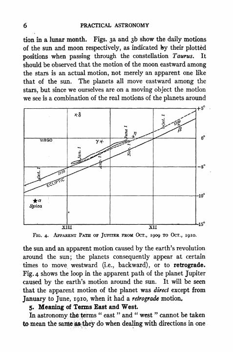
6 PRACTICAL ASTRONOMY
tion in a lunar month. Figs. 3a and 3b show the daily motions
of the sun and moon respectively, as indicated by their plotted
positions when passing through the constellation Taurus. It
should be observed that the motion of the moon eastward amongthe stars is an actual motion, not merely an apparent one like
that of the sun. The planets all move eastward among the
stars, but since we ourselves are on a moving object the motion
we see is a combination of the real motions of the planets around
JX1U XII
FIG. 4. APPARENT PATH or JUPITER FROM OCT., 1909 TO OCT., 1910.
the sun and an apparent motion caused by the earth's revolution
around the sun; the planets consequently appear at certain
times to move westward (i.e., backward), or to retrograde.
Fig. 4 shows the loop in the apparent path of the planet Jupiter
caused by the earth's motion around the sun. It will be seen
that the apparent motion of the planet was direct except from
January to June, 1910, when it had a retrograde motion,
5. Meaning of Terms East and West.
In astronomy the ^erms"east
" and " west"cannot be taken
tiO mean the saixie^tjjey do when dealing with directions in one
THE CELESTIAL SPHERE
plane. In plane surveying"east
" and " west "may be con-
sidered to mean the directions perpendicular to the meridian
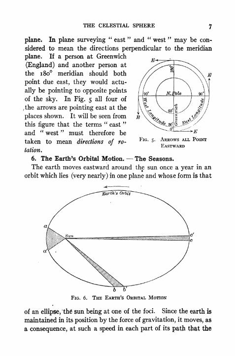
plane. If a person at Greenwich
(England) and another person at
the 180 meridian should both
point due east, they would actu-
ally be pointing to opposite points
of the sky. In Fig. 5 all four of
fthe arrows are pointing east at the
places shown. It will be seen from
this figure that the terms"east
"
and "west
" must therefore be
taken to mean directions of ro-
tation.
6. The Earth's Orbital Motion. The Seasons.
The earth moves eastward around the sun once a year in an
orbit which lies (very nearly) in one plane and whose form is that
FIG. 5. ARROWS ALL POINT
EASTWARD
FIG. 6. THE EARTH'S ORBITAL MOTION
of an ellipse, the sun being at one of the foci. Since the earth is
maintained in its position by the force of gravitation, it moves, as
a consequence, at such a speed in each part of its path that the

8 PRACTICAL ASTRONOMY
line joining the earth and sun moves over equal areas in equal
times. In Fig. 6 all of the shaded areas are equal and the arcs
aa', W, ccf
represent the distances passed over in the same num-ber of days,*
The axis of rotation of the earth is inclined to the plane of the
orbit at an angle of about 66f ,that is, the plane of the earth's
equator is inclined at an angle of about 23^ to the plane of the
orbit. This latter angle is known as the obliquity of the ecliptic.
(See Chapter II.) The direction of the earth's axis of rotation
is nearly constant and it therefore points nearly to the same
place in the sky year after year.
The changes in the seasons are a direct result of the inclination
of the axis and of the fact that the axis remains nearly parallel
Vernal Equinox
Summer Solstice
(June )
Autumnal Equinox(Sept. **)
FIG. 7. THE SEASONS
to itself. When the earth is in that part of the orbit where the
northern end of the axis is pointed away from the sun (Fig. 7)
it is winter in the northern hemisphere. The sun appears to be
* The eccentricity of the ellipse shown in Fig. 6 is exaggerated for the sake
of clearness ; the earth's orbit is in reality much more nearly circular, the
variation in the earth's distance from the sun being only about three per cent.

THE CELESTIAL SPHERE 9
farthest south about Dec. 21, and at this time the days are
shortest and the nights are longest. When the earth is in this
position, a plane through the axis and perpendicular to the plane
of the orbit will pass through the sun. About ten days later the
earth passes the end of the major axis of the ellipse and is at its
point of nearest approach to the sun, or perihelion. Althoughthe earth is really nearer to the sun in winter than in summer,this has but a small effect upon the seasons; the chief reasons
why it is colder in winter are that the day is shorter and the
rays of sunlight strike the surface of the ground more obliquely.
The sun appears to be farthest north about June 22, at which
time summer begins in the northern hemisphere and the days are
longest and the nights shortest. When the earth passes the
other end of the major axis of the ellipse it is farthest from the
sun, or at aphelion. On March 21 the sun is in the plane of
the earth's equator and day and night are of equal length at all
places on the earth (Fig. 7). On Sept. 22 the sun is again in
the plane of the equator and day and night are everywhere
equal. These two times are called the equinoxes (vernal and
autumnal), and the points in the sky where the sun's centre ap-
pears to be at these two dates are called the equinoctial points,
or more commonly the equinoxes.
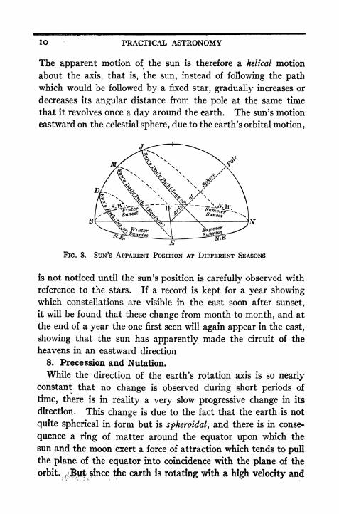
7. The Sun's Apparent Position at Different Seasons.
The apparent positions of the sun on the celestial sphere
corresponding to these different positions of the earth are shown
in Fig. 8. As a result of the sun's apparent eastward motion
from day to day along a path which is inclined to the equator,
the angular distance of the sun from the equator is continually
changing. Half of the year it is north of the equator and half of
the year it is south. On June 22 the sun is in its most northerly
position and is visible more than half the day to a person in the
northern hemisphere (/, Fig. 8). On Dec. 21 it is farthest south
of the equator and is visible less than half the day (D, Fig. 8).
In between these two extremes it moves back and forth across
the equator, passing it about March 21 and Sept. 22 each year.
10 PRACTICAL ASTRONOMY
The apparent motion of the sun is therefore a helical motion
about the axis, that is, the sun, instead of following the pathwhich would be followed by a fixed star, gradually increases or
decreases its angular distance from the pole at the same time
that it revolves once a day around the earth. The sun's motion
eastward on the celestial sphere, due to the earth's orbital motion,
E
FIG. 8. SUN'S APPARENT POSITION AT DIFFERENT SEASONS
is not noticed until the sun's position is carefully observed with
reference to the stars. If a record is kept for a year showingwhich constellations are visible in the east soon after sunset,
it will be found that these change from month to month, and at
the end of a year the one first seen will again appear in the east,
showing that the sun has apparently made the circuit of the
heavens in an eastward direction
8. Precession and Nutation.
While the direction of the earth's rotation axis is so nearlyconstant that no change is observed during short periods of
time, there is in reality a very slow progressive change in its
direction. This change is due to the fact that the earth is not
quite spherical in form but is spheroidal, and there is in conse-
quence a ring of matter around the equator upon which the
sun and the moon exert a force of attraction which tends to pull
the plane of the equator into coincidence with the plane of the
orbit.iif$y$ fince the earth is rotating with a high velocity and

THE CELESTIAL SPHERE II
resists this attraction, the actual effect is not to change per-
manently the inclination of the equator to the orbit, but first to
cause the earth's axis to describe a cone about an axis per-
pendicular to the drbit, and second to cause the inclination of
the axis to go through certain periodic changes (see Fig. 9). The
movement of the axis in a conical surface causes the line of
intersection of the equator and the plane of the orbit to revolve
slowly westward, the pole itself always moving directly toward
the vernal equinox. This causes the vernal equinox, F, to move
westward in the sky, and hence the sun crosses the equator each
spring earlier than it would otherwise; this is known as the
-Plcme-of-EariWTrOrbit-
FIG. 9. PRECESSION OF THE EQUINOXES
precession of the equinoxes. In Fig. 9 the pole occupies,, suc-
cessively the positions /, 2 and J, which causes the point V to
occupy points i, 2 and.?. This motion is but 50". 2 per year,
and it therefore requires about 25,800 years for the pole to make
one complete revolution. The force causing the precession is
not quite constant, and the motion of the equinoctial points is
therefore not perfectly uniform but has a small periodic varia-
tion. In addition to this periodic change in the rate of the
precession there is also a slight periodic change in the obliquity,
12 PRACTICAL ASTRONOMY
called Nutation. The maximum value of the nutation is about
9"; the period is about 19 years. The phenomenon of preces-
sion is clearly illustrated by means of the apparatus called the
gyroscope. As a result of the precessional movement of the
axis all of tfte stars gradually change their positions with refer-
ence to the plane of the equator and the position of the equinox.
The stars themselves have but a very slight angular motion,
this apparent change fn position being due almost entirely to the
change in the positions of the circles of reference.
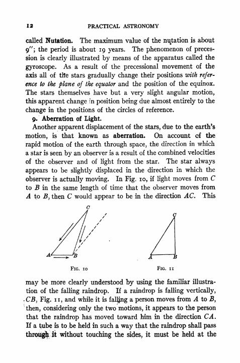
9. Aberration of Light.
Another apparent displacement of the stars, due to the earth's
motion, is that known as aberration. On account of the
rapid motion of the earth through space, the direction in which
a star is seen by an observer is a result of the combined velocities
of the observer and of light from the star. The star always
appears to be slightly displaced in the direction in which the
observer is actually moving. In Fig. 10, if light moves from Cto B in the same length of time that the observer moves from
A to J5, then C would appear to be in the direction AC. This
FIG. 10 FIG. ii
may be more clearly understood by using the familiar illustra-
tion of the falling raindrop. If a raindrop is falling vertically,
.CJ3, Fig. n, and while it is fal^ng a person moves from A to B,"
then, considering only the two motions, it appears to the person
that the raindrop has moved toward him in the direction CA.
If a t;ube is to ,be held in such a way that the raindrop shall pass
it without touching the sides, it must be held at the

THE CELESTIAL SPHERE IJ
inclination of AC. The apparent displacement of a star due
to the observer's motion is similar to the change in the apparentdirection of the raindrop.
There are two kinds of aberration, annual and diurnal.
Annual aberration is that produced by the earth's motion in its
orbit and is the same for all observers. Diurnal aberration is
due to the earth's daily rotation about its axis, and is different
in different latitudes, because the speed of a point on the earth's
surface is greatest at the equator and diminishes toward the pole.
If v represents the velocity of the earth in its orbit and V the
velocity of light, then when CB is at right angles to AB the
displacement is a maximum and
^tan <XQ
= ~,
where is the angular displacement and is called the "constant
of aberration." Its value is about 20.^5 . If CB is not per-
pendicular to AB) thenv . A
sin a. = ~ sin A
or approximately
where a is the angular displacement and B is the angle ABC.
tan a = sin a. = sin B,
CHAPTER II
DEFINITIONS POINTS AND CIRCLES OF REFERENCE
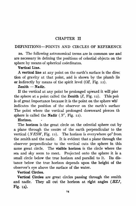
10. The following astronomical terms are in common use and
are necessary in defining the positions of celestial objects on the
sphere by means of spherical coordinates.
Vertical Line.
A vertical line at any point on the earth's surface is the direc
tion of gravity at that point, arid is shown by the plumb lin
or indirectly by means of the spirit level (OZ, Fig. 12).
Zenith Nadir,
If the vertical at any point be prolonged upward it will pier
the sphere at a point called the Zenith (Z, Fig. 12). This poi]
is of great importance because it is the point on the sphere whi
indicates the position of the observer on the earth's surface
The point where the vertical prolonged downward pierces th
sphere is called the Nadir (N', Fig. 12).
Horizon.
The horizon is the great circle on the celestial sphere cut bya plane through the centre of the earth perpendicular to the
vertical (NESW, Fig. 12). The horizon is everywhere 90 from
the zenith and the nadir. It is evident that a plane through the
observer perpendicular to the vertical cuts the sphere in this
same great circle. The visible horizon is the circle where the
sea and sky seem to meet. Projected onto the sphere it is a
small circle below the true horizon and parallel to it. Its dis-
tance below the true horizon depends upon the height of the
observer's eye above the surface of the water.
Vertical Circles.
Vertical Circles are great circles passing through the zenith
and nadir. They all cut the horizon at right angles (HZJ,
14

POINTS AND CIRCLES OF REFERENCE IS
Almucantars.
Parallels of altitude, or almucantars, are small circles parallel
to the horizon (DFG, Fig. 12).
Poles.
If the earth's axis of rotation be produced indefinitely it will
pierce the sphere in two points called the celestial poles (PP'
Fig. 12).
Equator.
The celestial equator is a great circle of the celestial sphere
Ut by a plane through the centre of the earth perpendicular to
FIG. 12. THE CELESTIAL SPHERE
the axis of rotation (QWRE, Fig. 12). It is everywhere 90from the poles. A parallel plane through the observer cuts the
sphere in the same circle.

jtf PRACTICAL ASTRONOMY
Hour Circles.
Hour Circles are great circles passing through the north and
south celestial poles (PVP', Fig. 12).
The 6-hour circle is the hour circle whose plane is perpendicu-
lar to that of the meridian.
Parallels of Declination.
Small circles parallel to the plane of the equator are called
parallels of declination (BKC, Fig. 12).
Meridian.
The meridian is the great circle passing through the zenith and
the poles (SZPL, Fig. 12). It is at once an hour circle and a
FIG. 12. THE CELESTIAL SPHERE
vertical circle, It is evident that different observers will in
general Jjave different meridians. The meridian cuts the horizon
in the norland south points (N, 5, Fig. 12). The intersection

POINTS AND CIRCLES OF REFERENCE if
of the plane of the meridian with the horizontal plane throughthe observer is the meridian line used in plane surveying.
Prime Vertical.
The prime vertical is the vertical circle whose plane is per-
pendicular to the plane of the meridian (EZW, Fig. 12). It
cuts the horizon in the east and west points (E, W, Fig. 12).
Ecliptic.
The ecliptic is the great circle on the celestial sphere whichv
'the sun's centre appears to describe during one year (AMVL,Fig. 12). Its plane is the plane of the earth's orbit; it is inclined
to the plane of the equator at an angle of about 23 27', called the
obliquity of the ecliptic.
Equinoxes.
The points of intersection of the ecliptic and the equator are
called the equinoctial points or simply the equinoxes. That
intersection at which the sun appears to cross the equator when
going from the south side to the north side is called the Vernal
Equinox, or sometimes the First Point of Aries (F, Fig. 12).
The sun reaches this point about March 21. The other inter-
section is called the Autumnal Equinox (A, Fig. 12).
Solstices.
The points on the ecliptic midway between the equinoxes are
called the winter and summer solstices.
Questions
1. What imaginary circles on the earth's surface correspond to hour circles?
To parallels of declination? To vertical circles?
2. What are the widths of the torrid, temperate and arctic zones and how are*
they determined?
CHAPTER III
SYSTEMS OF COORDINATES ON THE SPHERE
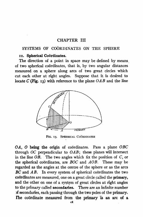
n. Spherical Coordinates.
The direction of a point in space may be defined by means
of two spherical coordinates, that is, by two angular distances
measured on a sphere along arcs of two great circles which
cut each other at right angles. Suppose that it is desired to
locate C (Fig. 13) with reference to the plane OAB and the line
FIG. 13. SpflERiCAL COORDINATES
OA, being the origin of coordinates. Pass a plane OBCthrough OC perpendicular to OAB; these planes will intersect
in the line OB. The two angles which fix the position of C, or
the spherical coordinates, are BOC and AOB. These may be
regarded as the angles at the centre of the sphere or as the arcs
BC and AB. In every system of spherical coordinates the two
codrdinates are measured, one on a great circle called the primary,
and the other on one of a system of great circles at right angles
to the primary called secondaries. There are an infinite numberrf secondaries, each passing through the two poles of the primary,
Fhe coordinate measured from the primary is an arc of aT*

SYSTEMS OF COORDINATES ON THE SPHERE K)
secoftdary circle; the coordinate measured between the secondary
circles is an arc of the primary.
12. Horizon System.
In this system the primary circle is the horizon and the sec-
ondaries are vertical circles, or circles passing through the zenith
and nadir. The first coordinate of a point is its angular distance
above the horizon, measured on a vertical circle; this is called
the Altitude. The complement of the altitude is called the
Zenith distance. The second coordinate is the angular distance
on the horizon between the meridian and the vertical circle
through the point; this is called the Azimuth. Azimuth may be
reckoned either from the north or the south point and in either
direction, like bearings in surveying, but the custom is to reckon
it from the south point right-handed from o to 360 except for
stars near the pole, in which case it is more convenient to reckon
W- Azimuth
FIG. 14. THE HORIZON SYSTEM
from the north, and either to the east or to the west. In Fig. 14
the altitude of the star A is BA\ its azimuth is SB.
13. The Equator Systems.
The circles of reference in this system are the equator and
great circles through the poles, or hour circles. The first coor-
dinate of a point is its angular distance north or south of the
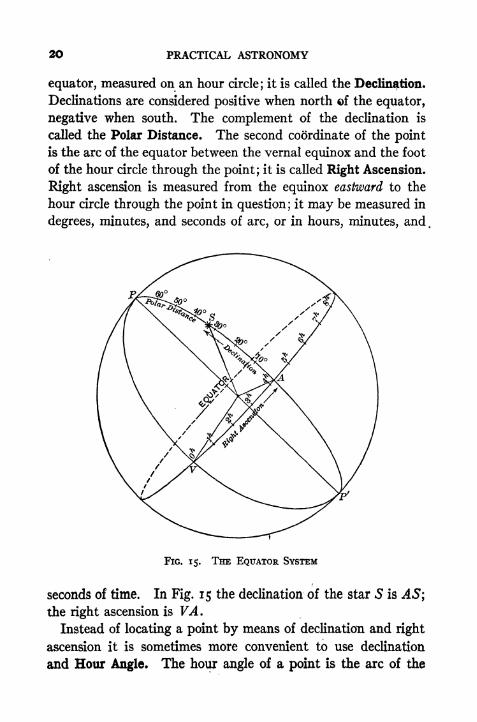
20 PRACTICAL ASTRONOMY
equator, measured on an hour circle; it is called the Declination.
Declinations are considered positive when north of the equator,
negative when south. The complement of the declination is
called the Polar Distance. The second coordinate of the point
is the arc of the equator between the vernal equinox and the foot
of the hour circle through the point; it is called Right Ascension.
Right ascension is measured from the equinox eastward to the
hour circle through the point in question; it may be measured in
degrees, minutes, and seconds of arc, or in hours, minutes, and,
FIG. 15. THE EQUATOR SYSTEM
seconds of time. In Fig. 15 the declination of the star S is -45;
the right ascension is VA.
Instead of locating a point by means of declination and right
ascension it is sometimes more convenient to use declination
and Hour Angle. The hour angle of a point is the arc of the

SYSTEMS OF COORDINATES ON THE SPHERE
equator between the observer's meridian and the hour circle
through the point. It is measured from the meridian westward
(clockwise) from oh to 24^ or from o to 360. In Fig. 16 the
declination of the star S is AS (negative); the hour angle is
FIG. 16. HOUR ANGLE AND DECLINATION
MA. For the measurement of time the hour angle may be
counted from the upper or the lower branch of the meridian.
These three systems are shown in the following table.
22 PRACTICAL ASTRONOMY
14. There is another system which is employed in some
branches of astronomy but will not be used in this book. The
coordinates are called celestial latitude and celestial longitude;
the primary circle is the ecliptic. Celestial latitude is measured
from the ecliptic just as declination is measured from the equator.
Celestial longitude is measured eastward along the ecliptic from
the equinox, just as right ascension is measured eastward along
the equator. The student should be careful not to confuse celes-
tial latitude and longitude with terrestrial latitude and longitude.
The latter are the ones used in the problems discussed in this book.
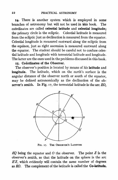
15. Coordinates of the Observer.
The observer's position is located by means of his latitude and
longitude. The latitude, which on the earth's surface is the
angular distance of the observer north or south of the equator,
may be defined astronomically as the declination of the ob-
server's zenith. In Fig. 17, the terrestrial latitude is the arc EO,
FIG. 17. THE OBSERVER'S LATITUDE
EQ being the equator and the observer. The point Z is the
observer's zenith, so that the latitude on the sphere is the arc
E'Z, which evidently will contain the same number of degrees
as EO. The complement of the latitude is called the Co-latitude.
SYSTEMS OF COORDINATES ON THE SPHERE 23
The terrestrial longitude of the observer is the arc of the equator
between the primary meridian (usually that of Greenwich) and
the meridian of the observer. On the celestial sphere the longi-
tude would be the arc of the celestial equator contained between
two hour circles whose planes are the planes of the two terrestrial
meridians.
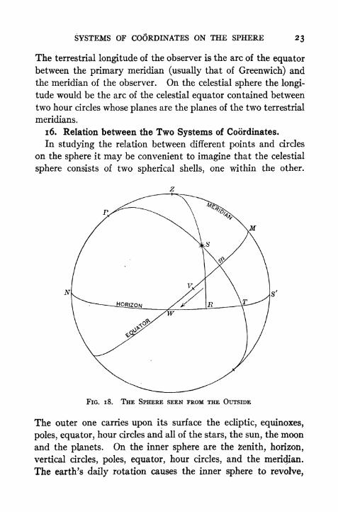
1 6. Relation between the Two Systems of Coordinates.
In studying the relation between different points and circles
on the sphere it may be convenient to imagine that the celestial
sphere consists of two spherical shells, one within the other.
FIG. 1 8. THE SPHERE SEEN FROM THE OUTSIDE
The outer one carries upon its surface the ecliptic, equinoxes,
poles, equator, hour circles and all of the stars, the sun, the moon
and the planets. On the inner sphere are the fcenith, horizon,
vertical circles, poles, equator, hour circles, and the meridian.
The earth's daily rotation causes the inner sphere to revolve,

24 PRACTICAL ASTRONOMY
while the outer sphere is motionless, or, regarding only
apparent motion, the outer sphere revolves once*per dayman Its
axis, while the inner sphere appears to be motionless. It is
evident that the coordinates of a fixed star in the first equatorial
system (Declination and Right Ascension) are practically alwaysthe same, whereas the coordinates in the horizon system are
continually changing. It will also be seen that in the first
equatorial system the coordinates are independent of the ob-
server's position, but in the horizon system they are entirely,
dependent upon his position. In the second equatorial systemone co5rdinate is independent of the observer, while the other
(hour angle) is not. In making up catalogues of the positions
of the stars it is necessary to use right ascensions and declina-
tions in defining these positions. When making observations
FIG. 19. PORTION OF THE SPHERE SEEN FROM THE EARTH (LOOKING SOUTH)
with instruments it is usually simpler to measure coordinates
in the horizon system. Therefore it is necessary to be able to
cbmpute the coordinates of one system from those of another.
The mathematical relations between the spherical coordinates
are discussed in Cha IV. *;

SYSTEMS OF COORDINATES ON THE SPHERE 2$
Figs. 18, 19, and 20 show three different views of the celestial
sphere with which the student should be familiar. Fig. 18 is
the sphere as seen from the outside and is the view best adaptedto showing problems in spherical trigonometry. The star S has
the altitude RS, azimuth S'R, hour angle Mm, right ascension
Vm, and declination mS\ the meridian is ZMS'. Fig. 19 shows
a portion of the sphere as seen by an observer looking southward;
the points are indicated by the same letters as in Fig. 18. Fig. 20
FIG. 20. THE SPHERE PROJECTED ONTO THE PLANE OF THE EQUATOR
shows the same points projected on the plane of the equator.
In this view of the sphere the angles at the pole (i.e., the
angles between hour circles) are shown their true size, and
it is therefore a convenient diagram to use when dealing with
right ascension and hour angles.

26 PRACTICAL ASTRONOMY
Questions and Problems
1. What coordinates on the sphere correspond to latitude and longitude on the
earth's surface?
2. Make a sketch of the sphere and plot the position of a star having an altitude
of 20 and an azimuth of 250. Locate a star whose hour angle is i6h and whose
decimation is ~io. Locate a star whose right ascension is gh and whose declina-
tion is N. 30.
3. If a star is on the equator and also on the horizon, what is its azimuth? Its
altitude? Its hour angle? Its declination?
4. What changes take place in the azimuth and altitude of a star during
twenty-four hours ?
5. What changes take place in the right ascension and declination of the ob-
server's zenith during a day ?
6. A person in latitude 40 N. observes a star, in the west, whose declination is
5 N. In what order will the star pass the following three circles; (a) the 6^ circle,
(b) the horizon, (c) the prime vertical ?

CHAPTER IV
RELATION BETWEEN COORDINATES
17. Relation between Altitude of Pole and Latitude of Ob-server.
In Fig. 21, SZN represents the observer's meridian; let P be
the celestial pole, Z the zenith,
E the point of intersection
of the meridian and the equa-
tor, and N and S the north
and south points of the ho-
rizon. By the definitions, CZ(vertical) is perpendicular to
SN (horizon) and CP (axis)
is perpendicular to EC (equator). Therefore the arc PN =
arc EZ. By the defini-
tions EZ is the declina-
tion of the zenith, or
the latitude, and PN is
the altitude of the ce-
lestial pole. Hence the
altitude of the pole is
always equal to the lati-
tude of the observer. Thesame relation may be
seen from Fig. 22, in
which NP is the north
pole of the earth, OH is
the plane of the hori-
zon, the observer being
FIG. 22 at O, EQ is the equator,
andOP' is a line parallel
to C-NP and consequently points to the celestial pole. It mayreadily be shown that ECO, the observer's latitude, equals

2$ PRACTICAL ASTRONOMY
HOP', the altitude of the celestial pole. A person at the equator
would see the north celestial pole in the north point of his horizon
and the south celestial pole in the south point of his horizon. If
he travelled northward the north pole would appear to rise, its
altitude being always equal to his latitude, while the south pole
would immediately go below his horizon. When the traveller
reached the north pole of the earth the north celestial pole
would be vertically over his head.
To a person at the equator all stars would appear to move
vertically at the times of rising and setting, ^nd all stars would
be above the horizon i2h and below i2h during o* - revolution
(S.Pole) S N (N.Pole)
PIG. 2$. THE RIGHT SPHERE
Appearance of Sphere to Observer at Earth's Equator.
of the sphere. All stars in both hemispheres would be above
the horizon at some time every day. (Fig. 23.)
If a person were at the earth's pole the celestial equator would
coincide with his horizon, and all stars in the northern hemi-
sphere would appear to travel around in circles parallel to the
horizon; they would be visible for 24* a day, and their altitudes
would not change. The stars in the southern hemisphere would
never be visible. The word north would cease to have its usual

RELATION BETWEEN COORDINATES 29
meaning, and south might mean any horizontal direction. The
longitude of a point on the earth and its azimuth from the
Greenwich meridian would then be the same. (Fig. 24.)
At all points between these two extreme latitudes the equatorcuts the horizon obliquely., } A star on the equator will be above
FIG. 24. THE PARALLEL SPHERE
Appearance of Sphere to Observer at Earth's Pole
the horizon half the time and below half the time. A star north
of the equator will (to a person in the northern hemisphere) be
above the horizon more than half of the day; a star south of the
equator will be above the horizon less than half of the day. If
the north polar distance of a star is less than the observer's north
latitude, the whole of the star's diurnal circle is above the hori-
zon, and the star will therefore remain above the horizon all
of the time. It is called in this case a circumpolar star (Fig.
25). The south circumpolar stars are those whose south polar
distances are less than the latitude; they are never visible tfc an

30 PRACTICAL ASTRONOMY
observer in the northern hemisphere. If the observer travels
jiorth until he is beyond the arctic circle, latitude" 66 33' north,
then the sun becomes a circumpolar at the time of the summer
solstice. At noon the sun would be at its maximum altitude;
at midnight it would be at its minimum altitude but would still
be above the horizon. This is called the"midnight sun."
Circumpolars(Never Rise)
FIG. 25. CtRcuMPOtAR STARS
18. Relation between Latitude of Observer, and the Declina-
tion and Altitude of a Point on the Meridian.
The relation between the latitude of the observer and the
declination and altitude of a point on the observer's meridian
may be seen by referring to Fig. 26. Let A be any point on the
meridian, such as a star or the centre of the sun, moon, or a
planet, located south of the zenith but north of the equator; then
EZ =4>, the latitude*
EA =5, the declination
SA =A, the meridian altitude
ZA = f ,the meridian zenith distance.
* The Greek alphabet is given oft p. 242.

RELATION BETWEEN COORDINATES 31
From the figure it is evident that
If A is south of the equator 6 becomes negative, but the same
equation applies in this case provided the quantities are given
FIG. 26. STAR ON THE MERIDIAN
their proper signs. If A is north of the zenith we should have= 8 f [2]; but if we regard f as negative when north of
the zenith and positive when south of the zenith, then equation
[i] covers all cases. When the point is below the pole the same
formula might be employed by counting the declination beyond
90. In such cases it is usually simpler to employ the polar
distance, p, instead of the declination.
If the star is north of the zenith but above the pole, as at B,
then since p = 90 6,
<t>= h-p. [3]
If B were below the pole we should have
t = h + p. [4]
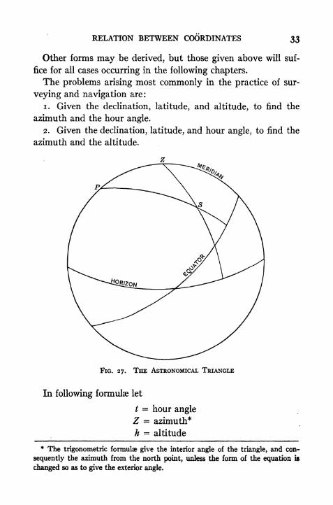
19. The Astronomical Triangle.
By joining the pole, zenith, and any star 5 on the sphere byarcs of great circles we obtain a triangle from which the relation
existing among the spherical coordinates may be obtained. This
triangle is so frequently employed in astronomy and navigation
that it is called the"astronomical triangle
"or the
" PZS
triangle." In Fig. 27 the arc PZ is the complement of the

32 PRACTICAL ASTRONOMY
latitude, or co-latitude; arc ZS is the zenith distance or com-
plement of the altitude; arc PS is the polar distance or com-
plement of the declination; the angle at P is the hour angle of
the star if S is west of the meridian, or 360 minus the hour angle
if S is east of the meridian; and Z is the azimuth of 5 (from
the north point), or 360 minus the azimuth, according as S is
west or east of the meridian. The angle at S is called the paral-
lactic angle. If any three parts of this triangle are known the
other three may be calculated. The fundamental formulae of,
spherical trigonometry are (see p, 257)
cos a = cos b cos c + sin b sin c cos A, [5]
sin a cos B = cos b sin c sin b cos c cos A, [6]
sin a sin B = sin b sin A. [7]
[f we put A =/, B = S, C = Z, a = 90
-h, b = 90
-*,
r = Q 5, then these three equations become
sin h = sin < sin 5 + cos<t>
cos 5 cos / [8]
cos h cos 5 = sin < cos 8 cos < sin 5 cos / [9]
cos h sin 5 = cos </> sin /. [10]
[f A =/, S = Z, C = 5, a = 90
-A, b = 90
-5, c = 90
-0,
then the [6] and [7] become
cos h cos Z = sin 6 cos cos 5 sin </> cos / [n]
cos h sin Z = cos 6 sin /. [12]
[f A = Z, J3 = 5, C =/, a = 90
-5, b = 90
-0, c = 90
-A,
then
sin 5 = sin < sin A + cos < cos A cos Z [13]
cos 5 cos 5 = sin < cos A cos < sin A cos Z [14]
cos 5 sin S = cos < sin Z. [15]
[f ,4 = Z, B =J, C = 5, a = 90
-5, b = 90
-A, c = 90
-0,
then
cos 5 cos / = sin h cos < cos h sin cos Z. [16]
RELATION BETWEEN COORDINATES 33
Other forms may be derived, but those given above will suf-
fice for all cases occurring in the following chapters.
The problems arising most commonly in the practice of sur-
veying and navigation are:
1. Given the declination, latitude, and altitude, to find the
azimuth and the hour angle.
2. Given the declination, latitude, and hour angle, to find the
azimuth and the altitude.
FIG. 27. THE ASTRONOMICAL TRIANGLE
In following formulae let
/ = hour angle
Z = azimuth*
h = altitude
* The trigonometric formulae give the interior angle of the triangle, and con-
sequently the azimuth from the north point, unless the form of the equation is
changed so as to give the exterior angle.

34 PRACTICAL ASTRONOMY
f = zenith distance
d declination
p =polar distance
<t>= latitude
and 5 = H0 + h + p).
For computing / any of the following formulae may be used.
sin ^ = V"* * Sm ~
}
[i7l-wcos sin p
coscos ('
- sn ('
tan
* cos </> sin p
__* / cos ^ sin (s
i
cos / =
-7-^ / ^\cos (5-
p) sm (5-
<t>)
sin A sin sin 5----
COS <t> COS d
r T
[2oJ .
cos / -- tan<t>tan d [200]
cos cos 5
cos (0 5) sin A r-,
vers / =-~ -~ --[21]
cos <t> cos 5
For computing the azimuth, Z, froni the north point either
toward the east or the west, we have
s.
n-
*) sn (j
COS COS
1 ^ A /COS ^ COS (3 p) r !COS * Z= V cosos/ [23]
tan * Z = i. - sn ,-
{
cos s cos (s />)
sin 6 sin <t> sin h r ,
COS Z =-- 21..-[25]
COS < COS A

RELATION BETWEEN COORDINATES 35
cos Z =-r tan 6 tan h [2 za]cos <j> cos h
cos (<}> h) sin 5 r rlvers Z =- --
:-
[26]cos <t>
cos /&
Only slight changes are necessary to adapt these to the direct
computation of Zs from the south point of the horizon. For
example, formulae [24], [25] and [26] would take the forms
cot t z, = I-
f jv cos s cos (s-
p)'
~ sin sin h sin 5 r Olcos Z, = ----
[28]cos cos h
cos (0 + h) + sin 5r 1vers Z, =-^ ! ^ ---29
cos cos h
While any of these formulae may be used to determine the
angle sought, the choice of formulae should depend somewhat
upon the precision with which the angle is defined by the func-
tion. If the angle is quite small it is more accurately found
through its sine than through its cosine; for an angle near 90the reverse is true. The tangent, however, on account of its
rapid variation, always gives the angle more precisely than either
the sine or the cosine. It will be observed that some of the for-
mulae require the use of both logarithmic and natural functions.
This causes no particular inconvenience in ordinary 5-place
computations because engineer's field and office tables almost
invariably contain both logarithmic and natural functions. If
7-place logarithmic tables are being used the other formulae
will be preferred.
The altitude of an object may be found from the formulae
sin h = cos (<t> 5) 2 cos <t> cos 5 sin2 1 / [30]
or sin h = cos (<t> 5) cos <t> cos 5 vers /, [300]
which may be derived from Equa. [8].

36 PRACTICAL ASTRONOMY
If the declination, hour angle, and altitude ajre given, the
azimuth is found by
sin Z = sin t cos 5 sec h. [31]
For computing the azimuth of a star near the pole when the
hour angle is known the following formula is frequently used:
r, sin t r -,
tan Z =: [32!
cos 4> tan 8 sin cos t
This equation may be derived by dividing [12] by [n] and then"
dividing by cos 8.
Body on the Horizon.
Given the latitude and declination, find the hour angle and
azimuth when the object is on the horizon. If in Equa. [8]
and [13] we put h =o, we have
cos / = tan d tan < [33]
and cosZ = sin 5 sec <. [34]
These formulae may be used to compute the time of sunrise or
sunset, and the sun's bearing at these times.
Greatest Elongation.
A special case of the PZS triangle which is of great practical
importance occurs when a star which culminates north of the
zenith is at its greatest elongation. When in this position the
azimuth of the star is a maximum and its diurnal circle is tan-
gent to the vertical circle through the star; the triangle is there-
fore right-angled at the point S (Fig. 28). The formulae for the
hour angle?and azimuth are
cos / = tan < cot 5 [35]
and sinZ = sin p sec <, [36]
from which the time of elongation and the bearing of the star
may be found. (See Art. 97.)
20. Relation between Right Ascension and Hour Angle.
In order to understand the relation between the right ascen-
sion and the hour angle of a point, we may think of the equa-

RELATION BETWEEN COORDINATES 37
E
FIG. 28. STAR AT GREATEST ELONGATION (EAST).
FIG. 29. RIGHT ASCENSION AND HOUR ANGUS

38 PRACTICAL ASTRONOMY
tor on the outer sphere as graduated into hour% minutes and
seconds of right ascension, zero being at the equinox and the
numbers increasing toward the east. The equator on the inner
sphere is graduated for hour angles, the zero being at the ob-
server's meridian and the numbers increasing toward the west.
(See Fig. 29.) As the outer sphere turns, the hour marks on
the right ascension scale will pass the meridian in the order of the
numbers. The number opposite the meridian at any instant
FIG. 30
shows how far the sphere has turned since the equinox was on
the meridian. If we read the hour angle scale opposite the
equinox, we obtain exactly the same number of hours. This
number of hours (or angle) may be considered as either the right
ascension of the meridian or the hour angle of the equinox.
In Fig. 30 the star S has an hour angle equal to AB and a right
ascension CB. The sum of these two angles is AC, or the hour
angle of the equinox. The same relation will be found to jbold

RELATION BETWEEN COORDINATES 39
true for all positions of S. The general relation existing between
these coordinates is, then,
Hour angle of Equinox = Hour angle of Star + Right Ascen-
sion of Star.
Questions and Problems
1. What is the greatest north declination a star may have and pass the meridian
to the south of the zenith?
2. What angle does the plane of the equator make with the horizon?
3. In what latitudes can the sun be overhead?
, 4. What is the altitude of the sun at noon in Boston (42 21' N.) on December
22?
5. What are the greatest and least angles made by the ecliptic with the hori-
zon at Boston?
6. In what latitudes is Vega (Decl. = 38 42' N.) a circumpolar star?
7. Make a sketch of the celestial sphere like Fig. 12 corresponding to a lati-
tude of 20 south and the instant when the vernal equinox is on the eastern horizon.
8. Derive formula [36].
9. Compute the hour angle of Vega when it is rising in latitude 40 North.
10. Compute the time of sunrise on June 22, in latitude 40 N.
CHAPTER V
MEASUREMENT OF TIME
21. The Earth's Rotation.
The measurement of intervals of time is made to depend uponthe period of the earth's rotation on its axis. Although the
period of rotation is not absolutely invariable, yet the variation?
are exceedingly small, and the rotation is assumed to be uniform.
The most natural unit of time for ordinary purposes is the solar
day, or the time corresponding to one rotation of the earth with
respect to the sun's direction. On*account of the motion of
the earth around the sun once a year the direction of this refer-
ence line is continually changing with reference to the direc-
tions of fixed stars, and the length of the solar day is not the
true time of one rotation of the earth. In some kinds of as-
tronomical work it is more convenient to employ a unit of time
based upon this true time of one rotation, namely, sidereal time
(or star time).
22. Transit or Culmination.
Every point on the celestial sphere crosses the plane of the
meridian of an observer twice during one revolution of the
sphere. The instant when any point on the celestial sphere is
on the meridian of an observer is called the time of transit, or
culmination, of that point over that meridian. When it is on
that half of the meridian containing the zenith, it is called the
upper transit; when it is on the other half it is called the lower
transit. Except in the case of stars near the elevated pole the
upper transit is the only one visible to the observer; hence whenthe transit of a star is mentioned the upper transit will be under-
stood unless the contrary is stated.
23. Sidereal Day.The sidereal day is the interval of time between two suc-
cessive upper transits of the vernal equinox over the same
40
MEASUREMENT OF TIME 41
meridian. If the equinox were fixed in position the sidereal dayas thus defined would be the true rotation period with reference
to the fixed stars, but since the equinox has a slow (and variable)
westward motion caused by the precessional movement of the
axis (see Art. 8) the actual interval between two transits of the
equinox differs about os.oi of time from the true time of one
rotation. The sidereal day actually used in practice, however,
is the one previously defined and not the true rotation period.
sflThis causes no inconvenience because sidereal days are not used
for reckoning long periods of time, dates always being givfcn in
solar days, so this error never becomes large. The sidereal dayis divided into 24 hours and each hour is subdivided into 60
minutes, and each minute into 60 seconds. When the vernal
equinox is at upper transit it is oft
,or the beginning of the side-
real day. This may be called"
sidereal noon/'
24. Sidereal Time.
The sidereal time at a given meridian at any specified instant
is equal to the hour angle of the vernal equinox measured from the
upper half of that meridian. It is therefore a measure of the
angle through which the earth has rotated since the equinoxwas on the meridian, and shows at once the position of the sphere
at this instant with respect to the observer's meridian.
25. Solar Day.
A solar day is the interval of time between two successive
lower transits of the sun's centre over the same meridian. The
lower transit is chosen in order that the date may change at
midnight. The solar day is divided into 24 hours, and each hour
is divided into 60 minutes, and each minute into 60 seconds.
When the centre of the sun is on the upper side of the meridian
(uppey transit) it is noon. When it is on the lower side it is
midnight. The instant of midnight is taken as o*, or the begin-
ning of the civil day.
26. Solar Time.
The solar time at any instant is equal to the hour angle of the
sun's centre plus 180 or 12 hours; in other words it is the hour
42 PRACTICAL ASTRONOMY
angle counted from the lower transit. It is the.angle through
which the earth has rotated, with respect to the sun's direc-
tion, since midnight, and measures the time interval that has
elapsed.
Since the earth revolves around the sun in an elliptical orbit
in accordance with the law of gravitation, the apparent angular
motion of the sun is not uniform, and the days are therefore of
different length at different seasons. In former times when sun
dials were considered sufficiently accurate for measuring time,
this lack of uniformity was unimportant. Under modern con-
ditions, which demand accurate measurement of time by the
use of clocks and chronometers, an invariable unit of time is
essential. The time ordinarily employed is that kept by a
fictitious point called the" mean sun/' which is imagined to
move at a uniform rate along the equator,* its rate of motion
being such that it makes one apparent revolution around the
earth in the same time as the actual sun, that is, in one year.
The fictitious sun is so placed that on the whole it precedes the
true sun as much as it follows it. The time indicated by the
position of the mean sun is called mean solar time. The. time
indicated by the position of the real sun is called apparent solar
time and is the time shown by a sun dial, or the time obtained
by direct instrumental observation of the sun's position. Meantime cannot, of course, be observed directly, but must be derived
by computation.
27. Equation of Time.
The difference between mean time and apparent time at anyinstant is called the equation of time and depends upon how much
the real sun is ahead of or behind its average position. It is given
in ordinary almanacs as" sun fast
"or
" sun slow." The
amount of this difference varies from about i^m to +i6m.
* This statement is true in a general way, but the motion is not strictly uniform
because the motion of the equinox itself is variable. The angle from the equinox
to the" mean sun
"at any instant is the sun's
" mean longitude"
(along the
ecliotic) plus small periodic terms.
MEASUREMENT OF TIME 43
The exact interval is "given in the American Ephemeris and in
the (small) Nautical Almanac for specified times each day.
This difference between the two kinds of time is due to several
causes, the chief of which are (i) the inequality of the earth's
angular motion in its orbit, and (2) the fact that the real sun
moves in the plane of the ecliptic and the mean sun in the plane
of the equator, and equal arcs on the ecliptic do not correspond
to equal arcs in the equator, or equal angles at the pole.fa In the winter, when the earth is nearest the sun, the rate of
angular motion about the sun is greater than in the summer
(see Art. 6). The sun will then appear to move eastward in the
sky at a faster rate than in summer, and its daily revolution about
the earth will therefore be slower. This delays the instant of
apparent noon, making the solar day longer than the average,
and therefore a sun dial will"
lose time." About April i the
sun is moving at its average rate and the sun dial ceases to lose
time; from this date until about July i the sun dial gains on
mean time, making up what it lost between Jan. i and April i.
During the other half of the year the process is reversed; the
sun dial gains from July i to Oct. i and loses from Oct. i to
Jan. i. The maximum difference due to this cause alone is*
*
about 8 minutes, either + or .
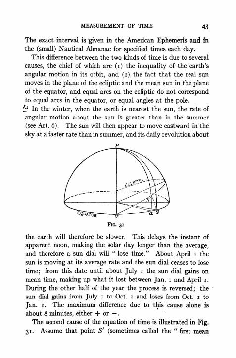
The second cause of the equation of time is illustrated in Fig.
31, Assume that point S' (sometimes called the"
first mean
44 PRACTICAL ASTRONOMY
sun ") moves uniformly along the ecliptic at the%average rate of
the actual sun; the time as indicated by this point will evidently
not be affected by the eccentricity of the orbit. If the mean
sun, S (also called the"second mean sun "), starts at F, the
vernal equinox, at the same instant that 5" starts, then the arcs
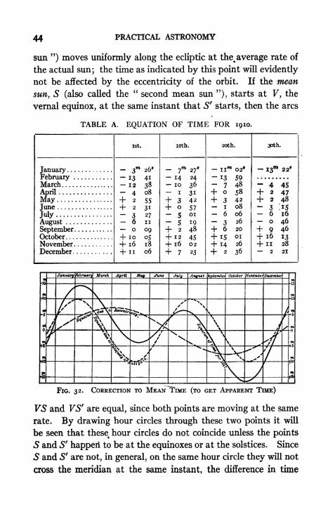
TABLE A. EQUATION OF TIME FOR 1910.
fr6n*ara! Mnrch
\\
KFIG. 32, CORRECTION TO MEAN TIME (TO GET APPARENT TIME)
VS and VSfare equal, since both points are moving at the same
rate. By drawing hour circles through these two points it will
be seen that these^ hour circles do not coincide unless the points
S and S' happeri to be at the equinoxes or at the solstices. Since
S and 5' are not, in general, on the same hour circle they will not
cross the meridian at the same instant, the difference in time

MEASUREMENT OF TIME 4$
being represented by the arc aS. The maximum length of aSis about 10 minutes of time, and may be either + or . Thecombined effect of these two causes, or the equation of time,
is shown in Table A and (graphically) in Fig. 32.
28. Conversion of Mean Time into Apparent Time and vice
versa.
Mean time may be converted into apparent time by adding
algebraically the equation of time for the instant. The value
i the equation of time is given in the American Ephemeris for
o* civil time (midnight) at Greenwich each day, together with
the proper algebraic sign. For any other time it must be found
by adding or subtracting the amount by which the equation has
increased or diminished since midnight. This correction is
obtained by multiplying the hours of the Greenwich Civil Time
by the variation per hour.
Example. Find the apparent time at Greenwich when the mean time (Civil)
is 14^ 30 on Oct. 28, 1925. The equation of time at o& Greenwich Civil Time is
-fi6m 053.00; the variation per hour is -fo.2i8. (The values are numerically in-
creasing.) The corrected equation of time at 14^ 30 is therefore +i6w 05*^00
+ i4*.S X o*.2i8 = +i6 o^.oo + 3*.i6 = i6 o8*.i6. The Greenwich Appar-ent Time is 14* 30 -f- i6 o8*.i6 = 14* 46"* o8*.i6.
When converting apparent time into mean time we may pro-
ceed in either of two ways. Since apparent time is given and
the equation is tabulated for mean time it is first necessary to
find the mean time with sufficient accuracy to enable us to take
out the correct equation of time.
Example. The Gr. Apparent Time is 14* 46^ 08*. 16 on Oct. 28, 1925; find the
Gr. Civil Time. Subtracting the approximate equation (-|-i6TO
05^.00) we obtain
14* 30 03* for the approximate Gr. Civil Time. The corrected equation is there-
fore -fi6 053.00 -f o*.2i8X 14^.5 - -fi6 o8*.i6 and the Gr. Civil Time is
14* 3o> oo.oo.
If preferred the Ephemeris of the sun for the meridian of
Washington (following the star lists) may be used. The equation!
for Washington Apparent noon Oct. 28, 1925, is i6m 08*49;
varia. per hour =~o*.i96. Since the longitude of Washing-
ton is 5* o8w
1 5*.78 west, the Washington Apparent Time corre-

46 PRACTICAL ASTRONOMY
spending to Greenwich Apparent Time 14^46^08^16 is 9* 38*
52*.38. The equation for this instant is i6m 08*49 + 0-196 X2^.35
= _^ o8*.o3. This fails to check the equation derived
above (+i6w o8s
.i6) because the method of interpolation is im-
perfect. If a more accurate interpolation formula is used the
results check to hundredths.
29. Astronomical Time Civil Time.
Previous to 1925 the time used in the Ephemens was As-
tronomical Time, in which oh occurred at the instant of noon,~
the hours being counted continuously up to 24*. In this systemthe date changed at noon, so that in the afternoon the Astro-
nomical and Civil dates agreed but in the forenoon they differed
one day. For example: f P.M. of Jan. 3 would be 7* Jan. 3
in astronomical time; but 3* A.M. of May n would be 15*, May10, when expressed in astronomical time.
Beginning with the issue for 1925 the time used in the Ephem-eris is designated as Civil Time, the hours being counted from"
midnight to midnight. The dates therefore change at mid-
night, as in ordinary civil time, the only difference being that
in the 24-hour system the afternoon hours are greater than 12.
For ordinary purposes we prefer to divide the day into halves
and to count from two zero points; from midnight to 'noon is
called A.M. (ante meridiem), and from noon to midnight is called
P.M. (post meridiem). When consulting the Ephemeris or the
Nautical Almanac itisjiecessary
to add i2hto the P.M. hours
before looking up corresponding quantities. The data found
opposite 3* are for 3* A.M.; those opposite 15* are for 3* P.M.
30. Relation between Longitude and Time.
The hour angle of the sun, counted from the lower meridian
of any place, is the solar time at that meridian, and will be
apparent or mean according to which sun is being considered.
The hour angle of the sun from the (lower) meridian of Green-
. wich is the corresponding Greenwich solar time. The difference
between the two times, or hour angles, is the longitude of the
place east or west of Greenwich, and expressed either in degrees
MEASUREMENT OF TIME 47
or in hours according as the hour angles are in degrees or in hours.
Similarly, the difference between the local solar times of anytwo places at a given instant is their difference in longitude in
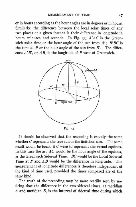
hours, minutes, and seconds. In Fig. 33, A'AC is the Green-
wich solar time or the hour angle of the sun from A'\ B'BC is
the time at P or the hour angle of the sun from B f. The differ-
ence A 'J3', or AB, is the longitude of P west of Greenwich.
Pole
*,wich
FIG. 33
It should be observed that the reasoning is exactly the same
whether C represents the true sun or the fictitious sun. The same
result would be found if C were to represent the vernal equinox.
[n this case the arc AC would be the hour angle of the equinox,
3r the Greenwich Sidereal Time. BC would be the Local Sidereal
Time at P and AB would be the difference in longitude. The
measurement of longitude differences is therefore independent of
the kind of time used, provided the times compared are of the
mme kind.
The truth of the preceding may be more readily seen by no-
ticing that the difference in the two sidereal times, at meridian
A and meridian B, is the interval of sidereal time during which
48 PRACTICAL ASTRONOMY
a star would appear to travel from A to B. Since the star re-
quires 24 sidereal hours to travel from A to A again, the time
interval AB bears the same relation to 24 sidereal hours that the
longitude difference bears to 360. The difference in the mean
solar times at A and B is the number of solar hours that the
mean sun would require to travel from A to 5; but since the
sun requires 24 solar hours to go from A to A again, the time
interval from A to B bears the same ratio to 24 solar hours that
the longitude difference bears to 360. The difference in longi-,
tude is correctly given when either time is used, provided the
same kind of time is used for both places.
To Change from Greenwich Time to Local Time or from Local
Time to Greenwich Time.
The method of changing from Greenwich to local time (and
the reverse) is illustrated by the following examples. Remem-ber that the more easterly place will have the later time.
Example i. The Greenwich Civil Time is 19* 40*" lo^.o. Required the civil
time at a meridian 4^ 50 2is .o West.
Gr. Civ. T. = igft 40 io*.o
Long. West = 4ft50*** 21^.0
Loc. Civ. T. = 14^ 49W 49^.0
P.M.
Example 2. The Greenwich Civil Time is 3^ oom. Required the local civil
time at a place whose longitude is 8* 00 West. In this instance the time at the
place is 8& earlier than 3^, that is it is 5^ before midnight of the preceding day, or
19^. This may also be obtained by adding 24* to the given 3* before subtracting
the longitude difference.
Gr. Civ. T. = 27* oo
Long. West = Sfi_Loc. Civ. T. = 19* oom
=fit oom P.M.
Example 3. The Greenwich Civil Time is 20^ oo. What is the time at a place
3ft east of Greenwich?
Gr. Civ. T. = so* oo>
Long. East = 3^ oo"*
Loc. Civ. T.
MEASUREMENT OF TIME 49
31. Relation between Hours and Degrees.
Since a circle may be divided either into 24* or into 360, the
relation between these two units is constant.
Since 24* = 360,
we have ih = 15,
im = IS
7
,
is =
is".
(Dividing the second equation by 15 we have
Am _ ,o.4 i
,
also 4*= i'.
By means of these two sets of equivalents, hours may be con-
verted into degrees, and degrees into hours without writing
down the intermediate steps. If it is desired to state the process
as a rule it may be done as follows: To convert degrees into hours,
divide the degrees by 15 and call the result hours; multiply the
remainder by 4 and call the result minutes; divide the minutes
(of an angle) by 15 and call the result minutes (of time); mul-
tiply the remainder by 4 and call it seconds; divide the seconds
(of angle) by 15 and call the result seconds (of time).
Example. Convert 47 if 35" into hours, minutes and seconds.
47 =45+ 2= 3*o8
if =i$
f
-f 2' = oi^oS*
35" - 30" + 5" -Q2*.33
Result = 3* ogm 10^.33
To convert hours into degrees, reverse this process.
Example. Convert 6* 35 51* into degrees, minutes, and seconds.
6* - 90
35m = 32" + 3ro - 8 45'
51*= 48* + 3*
- 1 2' 45"
Result = 98 57' 45"
One should be careful to use m and 5 for the minutes and sec-
onds corresponding to hours, and ',
"for the minutes and sec-
onds corresponding to degrees.

$0 PRACTICAL ASTRONOMY
It should be observed that the relation 15== i
his quite in-
dependent of the length of time which has elapsed. A star
requires one sidereal hour to increase its hour angle 15; the
sun requires one solar hour to increase its hour angle 15. In
the sense in which the term is used here ifl means primarily an
angle, not an absolute interval of time. It becomes an absolute
interval of time only when a particular kind of time is specified.
32. Standard Time.
From the definition of mean solar time it will be seen that at^
any given instant the solar times at two places will differ by an
amount equal to their difference in longitude expressed in hours,
minutes, and seconds. Before 1883 it was customary in this
country for each large city or town to use the mean solar time of
a meridian passing through that place, and for the smaller towns
in that vicinity to adopt the same time. Before railroad travel
became extensive this change of time from one place to another
caused no great difficulty, but with the increased amount of
railroad and telegraph business these frequent and irregular
changes of time became so inconvenient and confusing that in
1883 a uniform system of time was adopted. The country is
divided into time belts, each one theoretically 15 wide. These
are known as the Eastern, Central, Mountain, and Pacific time
belts. All places within these belts use the mean local time of
the 75, 90, 105, and 120 meridians respectively. The time
of the 60 meridian is called Atlantic time and is used in the
Eastern part of Canada. The actual positions of the dividing
lines between these time belts depend partly upon the location
of the large cities and the points at which the railway companies
change their time. The lines shown in Fig. 34 are in accordance
with the decisions of the Interstate Commerce Commission in
1918. Wherever the change of time occurs the amount of the
change is always exactly one hour. The minutes and seconds
of all clocks are the same as those of the Greenwich clock. Whenit is noon at Greenwich it is f A.M. Eastern time, 6* A.M. Central
time, $hA.M. Mountain time, and 4* A.M. Pacific time.

MEASUREMENT OF TIME
2 PRACTICAL ASTRONOMY
Standard time is now in use in the principal countries of the
world; in most cases the systems of standard time are based on
the meridian of Greenwich.
Daylight Saving time for any locality is the time of a belt that
lies one hour to the east of the place in question. If, for ex-
ample, in the Eastern States the clocks are set to agree with those
of the Atlantic time belt (60 meridian west) this is designated
as daylight saving time in the Eastern time belt.
To Change from Local to Standard Time or the Contrary.
The change from local to standard time, or the contrary, is
made by expressing the difference in longitude between the given
meridian and the standard meridian in units of time and addingor subtracting this correction, remembering that the farther
west a place is the earlier it is in the day at the given instant of
time.
Example i. Find the standard time at a place 71 West of Greenwich when the
local time is 4* 20 oo* P.M. In longitude 71 the standard time would be that of
the 75 meridian. The difference in longitude is 4 = i6m . Since the standard
meridian is west of the 71 meridian the time there is i6TO earlier than the local time.
The standard time is therefore 4^ 04 oo* P.M.
Example 2. Find the local time at a place 91 West of Greenwich when the
Central Standard time is pft oow oo A.M. The difference in longitude is i = 4.Since the place is west of the 90 meridian the local time is earlier. The local time
is therefore 8* 56 oos A.M.
33. Relation between Sidereal Time, Right Ascension, and
Hour Angle of any Point at a Given Instant.
In Fig. 35 the hour angle of the equinox, or local sidereal time,
at the meridian of P, is the arc A V. The hour angle of the
star S at the meridian of P is the arc AB. The right ascension
of the star 5 is the arc VB. It is evident from the figure that
AV = VB + ABor 5 = a + t [37]
where 5 = the sidereal time at P, a = the right ascension and'
/ = the hour angle of the star. This relation is a general one
will be founcl to hold true for all positions, except that it
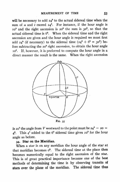
MEASUREMENT OF TIME S3
will be necessary to add 24* to the actual sidereal time when the
sum of a and t exceed 24*. For instance, if the hour angle is
10* and the right ascension is 20* the sum is 30*, so that the
actual sidereal time is 6*. When the sidereal time and the right
ascension are given and the hour angle is required we must first
add 24* (if necessary) to the sidereal time (24* + 6* =30*) be-
fore subtracting the 2oh right ascension, to obtain the hour angle
10* . If, however, it is preferred to compute the hour angle in a
direct manner the result is the same. When the right ascension
Pole
FIG. 35
is 20* the angle from V westward to the point must be 24* 20 =
4*. This 4* added to the 6* sidereal time gives 10* for the hour
angle as before.
34. Star on the Meridian.
When a star is on any meridian the hour angle of the star at
that meridian becomes o*. The sidereal time at the place then
becomes numerically equal to the right ascension of the star.
This is of great practical importance because one of the best
methods of determining the time is by observing transits of
stars over the plane of the meridian. The sidereal time thus

54 PRACTICAL ASTRONOMY
becomes known at once when a star of known, right ascension
is on the meridian.
35. Mean Solar and Sidereal Intervals of Time.
It has already been stated that on account of the earth's
orbital motion the sun has an apparent eastward motion amongthe stars of nearly i per day. This eastward motion of the sun
makes the intervals between the sun's transits greater by nearly
FIG. 36
4m than the interval between the transits of the equinox, that is,
the solar day is nearly 4 longer than the sidereal day. In
Fig. 36, let C and C" represent the positions of the earth on two
consecutive days. When the observer is at it is noon at his
meridian. After the earth makes one complete rotation (with
reference to a fixed star) the observer will be at 0', and the side-
real time will be exactly the same as it was the day before whenhe was at O. But the sun's direction is How CO", so the earth
must turn through an additional degree (nearly) until the sun is
again on this observer's meridian. This will require nearly 4*
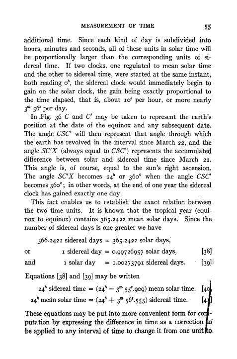
MEASUREMENT OF TIME 55
additional time. Since each kind of day is subdivided into
hours, minutes and seconds, all of these units in solar time will
be proportionally larger than the corresponding units of si-
dereal time. If two clocks, one regulated to mean solar time
and the other to sidereal time, were started at the same instant,
both reading OA,the sidereal clock would immediately begin to
gain on the solar clock, the gain being exactly proportional to
the time elapsed, that is, about io5
per hour, or more nearly
3m
56^ per day.
In Jig. 36 C and C may be taken to represent the earth's
position at the date of the equinox and any subsequent date.
The angle CSC will then represent that angle through which
the earth has revolved in the interval since March 22, and the
angle SC'X (always equal to CSC') represents the accumulated
difference between solar and sidereal time since March 22.
This angle is, of course, equal to the sun's right ascension.
The angle SC'X becomes 24* or 360 when the angle CSCbecomes 360; in other words, at the end of one year the sidereal
clock has gained exactly one day.
This fact enables us to establish the exact relation between
the two time units. It is known that the tropical year (equi-
nox to equinox) contains 365.2422 mean solar days. Since the
number of sidereal days is one greater we have
366.2422 sidereal days == 365.2422 solar days,
or i sidereal day = 0.99726957 solar days, [38]
and i solar day = 1.00273791 sidereal days. [39]!
Equations [38] and [39] may be written -
24* sidereal time = (24* 3 SS'.gog) mean solar time.[40)
24* medn solar time = (24* + 3 56^.555) sidereal time.[4]
These equations may be put into more convenient form for
putation by expressing the difference in time as a correction
be applied to any interval of time to change it from one unit

$6 PRACTICAL ASTRONOMY
the other. If Im is a mean solar interval and /,4:he correspond-
ing number of sidereal units, then
Is= Im + 0.00273791 X Im [42]
and lm = Is-
0.00273043 X Is , [43]
These give +9s
.8s65 and gs
.&2<)6 as the corresponding cor-
rections for one hour of solar and sidereal time respectively.
Tables II and III (pp. 227-8) were constructed by multiplying
different values of Im and Is by the constants in Equa. [42] and *
[43]. More extended tables (II and III) will be found in the1
Ephemeris.
Example i. Assuming that a sidereal chronometer and a solar clock start
together at a zero reading, what will be the reading of the solar clock when the
sidereal chronometer reads 9^ 23 5i5.o? From Table II, opposite 9^, is the cor-
rection im 28*466; opposite 23 and in the 4th column is 3*. 768, and opposite
51* and in the last column is 0^139. The sum of these three partial corrections is
xw 32^373; 9ft23"* 51*. 1 32^.373 = 9^ 22 185.627, the reading of the solar
clock.
Example 2. Reduce 7^ iom in solar time units to the corresponding interval in
sidereal time units. In Table III the correction for 7** is +iw 085.995; for lo"1 it
is -l-is-643. The sum, i"> 103.638, added to 7** iom gives 7* n 108.638 of sidereal
time.
It should be remembered that the conversion of time dis-
cussed above concerns the change of a short interval of time from
one kind of unit to another, and is like changing a distance from
yards to metres. When changing a long interval of time such,
for example, as finding the local sidereal time on Aug. i, when the
local solar time is ioft
A.M., we make use of the total accumulated
difference between the two times since March 22, which is the
same thing as the right ascension of the mean sun.
36. Approximate Corrections.
Since both corrections are nearly equal to 10* per hpur, or 4
per day, we may use these as rough approximations. For a still
closer correction we may allow 10* per hour and then deduct
i* for each 6* in the interval. The correction for 6* would then
be 6 X 10* i* = 59*. The error of this correction is but
MEASUREMENT OF TIME 57
0^.023 per hour for solar time and 0^.004 per hour for sidereal
time.
37. Relation between Sidereal Time and Mean Solar Time at
any Instant.
If in Fig. 35, Art. 37, the point B is taken to represent the
mean sun, then equation [37] becomes
S = <xs + ts [44]
in which as and ts are the right ascension and hour angle of the
mean sun at the instant considered. If the civil time is repre-
sented by T then ts= T + 12", and
S = as + T + i2 ft
[45]
which enables us to find sidereal time when civil time is given
and vice versa. If the equation is written
5 - T = as + I2h
, [46]
then, since the value of as does not depend upon the time at
any place but only upon the absolute instant of time considered,
it is evident that the difference between sidereal time and civil
time at any instant is the same for all places on the earth. Thevalues of S and T will be different at different meridians, but
the difference, S T, is the same for all places at the given
instant.
In order that Equa. [45] shall hold true it is essential that as
and T shall refer to the same position of the sun, that is, to the
same absolute instant of time. The right ascension of the meansun obtained from the Ephemeris is its value of o* of Greenwich
Civil Time. To reduce this right ascension to its value at the
desired instant it is necessary to increase it by a correction equal
to the product of the hourly increase in the right ascension
times the number of hours elapsed since midnight, that is, bythe number of hours in the Greenwich Civil Time (T). The
hourly increase in the right ascension of the mean sun is constant
and equal to +9^.8565 per solar hour. This is the same quantity
that was tabulated as the"reduction from solar to sidereal

58 PRACTICAL ASTRONOMY
units of time" and is given in Table III. The difference be-
tween solar and sidereal time is due to the fact that the sun's
right ascension increases, hence the two are numerically the
same. It is not necessary in practice to multiply the above
constant by the hours of the civil time, but the correction maybe looked up at once in Table III. Similarly, Table II furnishes
at once the correction to the right ascension for any number of
sidereal hours. Equation [45] will not hold true, therefore,
until the above correction to as has been made, and this cor-
rection may be regarded either as the increase in the right ascen-
sion or as the change from solar to sidereal time, or the contrary.
Suppose that the sun S (Fig. 37) and a star 5' passed the
meridian opposite M at the same instant, and that at the civil
time T it is desired to compute the corresponding sidereal time.
Since the sun is apparently moving at a slower rate than the
star, it will describe the arc M'MS (= T) while the star describes
the arc M'MS'. The arc SS' represents the gain of sidereal
time on mean time during the mean time interval T. , But S'

MEASUREMENT OF TIME 59
is the position of the sun at oh and FS" is the right ascension
(as) at o". The required,right ascension is VS (or as at time J)so as at o
h must be increased by the amount SS', or the correction
from Table III corresponding to T hours.
The right ascension of the mean sun is given in the Ephemerisas
"sidereal time of o* G. C. T." or
"right ascension of the
mean sun + 12*." For convenience we may write Equa. [45]
in the form
S =(as + i2) + T
[4Sa]
in which it is understood that a correction (Table III) is to be
added to reduce the interval T to sidereal units.
If the student has difficulty in understanding the process
indicated by Equa. [450] it may be helpful to remember that
all the quantities represented are really angles, and may be ex-
pressed in degrees, minutes, and seconds. If all three parts,
the sun's right ascension + 12", the hour angle of the mean sun
from the lower meridian (T), and the increase in the sun's right
ascension since midnight (Table III), are expressed as angles
then it is not difficult to see that the hour angle of the equinoxis the sum of these three parts.
Another view of it is that the actual sidereal time interval
from the transit of the equinox over the upper meridian to the
transit of the" mean sun
"over the lower meridian (midnight)
is as + i2h
;to obtain the sidereal time (since the upper transit
of the equinox) we must add to this the sidereal time interval
since midnight, which is the mean time interval since mid-
night plus the correction in Table III.
Example i. To find the Greenwich Sidereal Time corresponding to the Green-
wich Civil Time 9* oo" oo* on Jan. 7, 1925. The "right ascension of the mean sun
-f 12*"
for Jan. 7, 1925, is 7^ 04 090.74. The correction in Table III for o* is
4-i" 28^.71. The sidereal time is then found as follows:
(as 4- 12*) at o* = 7* 04m 09*.74
T = 9 oo oo
Table III = i 28 .71
5 = 16* osm

60 PRACTICAL ASTRONOMY
If it is desired to find the civil time T when the sidereal time
S is given, the equation is
T = S -(as + 12 ,. [456]
In this instance it is not possible to correct the right ascension
at once for the change since oh,for that is not yet known. It is
possible, however, to find the number of sidereal hours since
midnight, for this results directly from the subtraction of the
tabulated value of (as + i2h) from S. T is therefore found by
subtracting from this last result the corresponding correction
in Table II.
Example 2. If the Greenwich sidereal time i6> 05"* 38*45 had been given, to
find the civil time, we should first subtract from S the tabulated value of <xs + 12^,
obtaining the sidereal interval of time since midnight. This interval less the
correction in Table II is the civil time, T.
S = i6^os> 38*45
(as + i2) at o = 7 04 09 .74
Sidereal interval = 9*01 28^71
From Table II we find
for 9* - im 28*466
for Iaa .164
for 28*. 7 1= .078
total corr. = im 28^.708
Subtracting this from the above sidereal interval we have
T =9> oo> oo*.
Example 3. If the time given is that for a meridian other than that of Green-
wich the corresponding Greenwich time may be found at once (Art. 30) and the
problem solved as before. Suppose that the civil time is n ft at a place 60 (- 4*)
west of Greenwich and the date is May i, 1925. The right ascension
33" 36X86. Then,
Local Civil Time = u^ oo oo*
Add Longitude W. = 4 oo oo
Gr. Civil Time = 15^ oo oo*
(as H- i2) at o = 14 33 36 .86
Table III = 2 27 .85
Gr. Sid. Time -29^ 36 04*. 71
Subtract Long. W. =j
Loc. Sid. Time 2536o4*.7i
.71
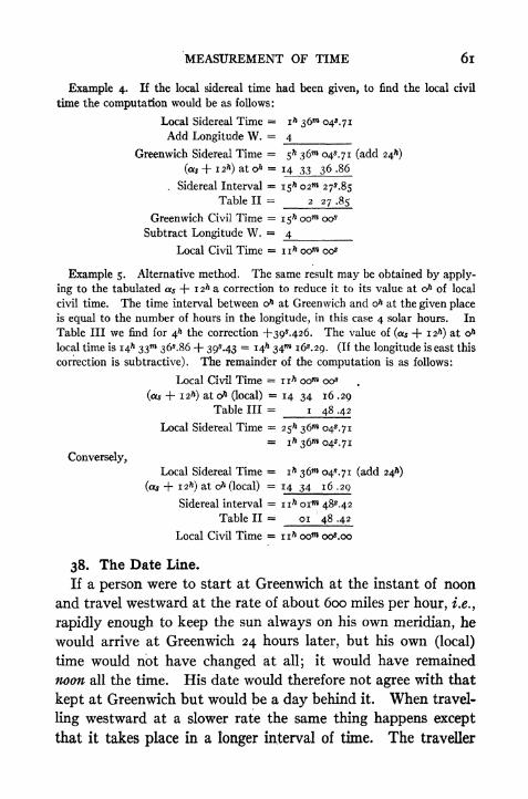
MEASUREMENT OF TIME 6l
Example 4. If the local sidereal time had been given, to find the local civil
time the computation would be as follows:
Local Sidereal Time == ih 36 04*. 71
Add Longitude W. =4.
Greenwich Sidereal Time = 5* 36 043.71 (add 24^)
(as + I2>) at o> = 14 33 36 .86
. Sidereal Interval = i$h 02 27^.85
Table II = 2 27.85
Greenwich Civil Time =1$** oom oo*
Subtract Longitude W. =_4
Local Civil Time = n^ oom 00*
Example 5. Alternative method. The same result may be obtained by apply-
ing to the tabulated as + 12^ a correction to reduce it to its value at o^ of local
civil time. The time interval between o& at Greenwich and oft at the given place
is equal to the number of hours in the longitude, in this case 4 solar hours. In
Table III we find for 4h the correction +393.426. The value of (as + 12^) at o&
local time is 14** 33 36*.86 + 39M3 = 14^ 34W 163.29. (If the longitude is east this
correction is subtractive). The remainder of the computation is as follows:
Local Civil Time = 1 1* oom oo3
(as -f- i zh) at o^ (local)= 14 34 16 .29
Table III == i 48 .42
Local Sidereal Time = 25^ 36 043.71= i& 36"* 043.71
Conversely,
Local Sidereal Time = ih 36*** 043.71 (add 24*)
(as + 1 2*) at o7*(local) = 14 34 16 .29
Sidereal interval = n 7* oim 483.42
Table II = 01 48 .42
Local Civil Time = nft oom oo*.oo
38. The Date Line.
If a person were to start at Greenwich at the instant of noon
and travel westward at the rate of about 600 miles per hour, i.e.,
rapidly enough to keep the sun always on his own meridian, he
would arrive at Greenwich 24 hours later, but his own (local)
time would not have changed at all; it would have remained
noon all the time. His date would therefore not agree with that
kept at Greenwich but would be a day behind it. When travel-
ling westward at a slower rate the same thing happens except
that it takes place in a longer interval of time. The traveller

62 PRACTICAL ASTRONOMY
has to set his watch back a little every day in prder to keep it
regulated to the meridian at which his noon occurs. As a con-
sequence, after he has circumnavigated the globe, his watch has
recorded one day less than it has actually run, and his calendar
is one day behind that of a person who remained at Greenwich.
If the traveller goes east he has to set his watch .ahead every day,
and, after circumnavigating the globe, his calendar is one dayahead of what it should be. In order to avoid these discrepancies
in dates it has been agreed to change the date when crossing the
180 meridian from Greenwich. Whenever a ship crosses the
180 meridian, going westward, a day is omitted from the cal-
endar; when going eastward, a day is repeated. As a matter
of practice the change is made at the midnight occurring
nearest the 180 meridian. For example, a steamer leaving
Yokohama July i6th at noon passed the 180 meridian about
4 P.M. of the 22d. At midnight, when the date was to be
changed, the calendar was set back one day. Her log there-
fore shows two days dated Monday, July 22. She arrived
at San Francisco on Aug. i at noon, having taken 17 days for
the trip.
The international date line actually used does not follow the
180 meridian in all places, but deviates so as to avoid separating
the Aleutian Islands, and in the South Pacific Ocean it passes
east of several groups of islands so as not to change the date
formerly used in these islands.
39. The Calendar.
Previous to the time of Julius Caesar the calendar was based
upon the lunar month, and, as this resulted in a continual change
in the dates at which the seasons occurred, the calendar was
frequently changed in an arbitrary manner in order to keep the
seasons in their places. This resulted in extreme confusion in
the dates. In the year 45 B.C., Julius Caesar reformed the
calendar and introduced one based on a year of 365! days, since
called the Julian Calendar. The J day was provided for by
making the ordinary year contain 365" days, but every fourth
MEASUREMENT OF TIME 63
year, called leap year, was given 366 days. The extra day was
added to February in such years as were divisible by 4.
Since the year actually contains 365^ 5* 48 46*, this differ-
ence of nm14* caused a gradual change in the dates at which
the seasons occurred. After many centuries the difference had
accumulated to about 10 days. In order to rectify this error
Pope Gregory XIII, in 1582, ordered that the calendar should
be corrected by dropping ten days and that future dates should
be computed by omitting the 366th day in those leap years
which occurred in century years not divisible by 400; that is,
such years as 1700, 1800, 1900 should not be counted as leap
years.
This change was at once adopted by the Catholic nations.
In England it was not adopted until 1752, at which time the
error had accumulated to n days. Up to that time the legal
year had begun on March 25, and the dates were reckoned ac-
cording to the Julian Calendar. When consulting records re-
ferring to dates previous to 1752 it is necessary to determine
whether they are dated according to" Old Style
"or
" New
Style." The date March 5, 1740, would now be written March
16, 1741. "Double dating/7
such as 1740-1, is frequently
used to avoid ambiguity.
Questions and Problems
1. If a sun dial shows the time to be g7* A.M. on May i, 1025, at a place in longi-
tude 71 West what is the corresponding Eastern Standard Time? The corrected
equation of time is + 2 56*.
2. When it is apparent noon on Oct. i, 1925, at a place in longitude 76 West
what is the Eastern Standard Time? The corrected equation of time is -f 10"* 17*.
3. Make a design for a horizontal sun dial for a place whose latitude is 42 21' N.
The gnomon ad (Fig. 38), or line which casts the shadow on the horizontal plane,
must be parallel to the earth's rotation axis; the angle which the gnomon makes
with the horizontal plane therefore equals the latitude. The shadow lines for the
hours (X, XI, XII, I, II, etc.) are found by passing planes through the gnomonand finding where they cut the horizontal plane of the dial. The vertical planeadb coincides with the meridian and therefore is the noon (XII*) line. The other
planes make, with the vertical plane, angles equal to some multiple of 15. In
finding the trace dc of one of these planes on the dial it should be observed that the

64 PRACTICAL ASTRONOMY
foot of the gnomon, d}is a point common to all such traces. In order to find an-
other point c on any trace, or shadow line, pass a plane abc through some point a on
the gnomon and perpendicular to it. This plane (the plane of the equator) will cut
an east and west line ce on the dial. If a line be drawn in this plane making an
angle of n X 15 with the meridian plane, it will cut ce at a point c which is on the
shadow line. Joining c with the foot of the gnomon gives the required line.
In making a design for a sun dial it must be remembered that the west edge of
the gnomon casts the shadow in the forenoon and the east edge in the afternoon;
there will be of course two noon lines, and the two halves of the diagram will be
symmetrical and separated from each other by the thickness of the gnomon. The
d
FIG. 38
dial may be placed in position by levelling the horizontal surface and then com-
puting the watch time of apparent noon and turning the dial so that the shadow is
on the XII* line at the calculated time.
Prove that the horizontal angle bdc is given by the relation
tan bdc = tan t sin <,
in which / is the sun's hour angle and < is the latitude.
4. Prove that the difference in longitude of two points is independent of the
kind of time used, by selecting two points at which the solar time differs by say3*, and then converting the solar time at each place into sidereal time.
5. On Jan. 20, 1925, the Eastern Standard Time at a certain instant is 7^30"*P.M. (Civ. T. 19* 3o). What is the local sidereal time at this instant at a placein longitude 72 10' West? (Right ascension of Mean Sun + i2 at o* G. C. T. =7h55m
25s-o.)
6. At a place in longitude 87 30' West the local sidereal time is found to be
19* 13** ios.5 on Sept. 30, 1925. What is the Central Standard Time at this in-
stant? (The right ascension of Mean Sun -f 12* at o* G. C. T. = 0*32^ S3*.2.)
7. If a vessel leaves San Francisco on July 16 and makes the trip in 17 days,on what date will she arrive at Yokohama?

CHAPTER VI
THE AMERICAN EPHEMERIS AND NAUTICALALMANAC STAR CATALOGUES INTERPOLATION
40. The Ephemeris.In discussing the problems of the previous chapters it has
been assumed that the right ascensions and declinations of the
celestial objects and the various other data mentioned are knownto the computer. These data consist of results calculated from
observations made with large instruments at the astronomical
observatories, and are published by the Government (Navy
Dept.) in the American Ephemeris and Nautical Almanac.
This may be obtained a year or two in advance from the Super-
intendent of Documents, Washington, D.C., price one dollar,
It contains the coordinates of the sun, moon, planets, and stars,
as well as the semidiameters, parallaxes, the equation of time,
and other necessary data.
It should be observed that the quantities given in the Almanac
vary with the time and are therefore computed for equidistant
intervals of solar time at some assumed meridian, usually that
of the Greenwich (England) Observatory.
The Ephemeris is divided into three principal parts. Part
I contains the data for the sun, moon, and planets, at stated
hours of Greenwich Civil Time, usually at o* (midnight), or the
beginning of the Civil Day. (Previous to 1925 such data were
given for Greenwich Mean Noon.) Part II contains the lists
of star places, the data being referred to the meridian of the
U. S. Naval Observatory at Washington (5*08 1 5^.78 west of
Greenwich); the instant being that of transit. Part III con-
* Similar publications by other governments are: The Nautical Almanac (Great
Britain), Berliner Astronomisches Jahrbuch (Germany), Connaissance des Temps
(France), and Almanaque Nautico (Spain).
65
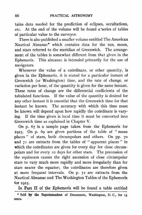
66 PRACTICAL ASTRONOMY
tains data needed for the prediction of eclipses, occupations,
etc. At the end of the volume will be found a "series of tables
of particular value to the surveyor.
There is also published a smaller volume entitled The American
Nautical Almanac* which contains data for the sun, moon,
and stars referred to the meridian of Greenwich. The arrange-
ment of the tables is somewhat different from that given in the
Ephemeris. This almanac is intended primarily for the use of
navigators.
Whenever the value of a coordinate, or other quantity, is
given in the Ephemeris, it is stated for a particular instant of
Greenwich (or Washington) time, and the rate of change, or
variation per hour, of the quantity is given for the same instant.
These rates of change are the differential coefficients of the
tabulated functions. If the value of the quantity is desired for
any other instant it is essential that the Greenwich time for that
instant be known. The accuracy with which this time must
be known will depend upon how rapidly the coordinate is vary-
ing. If the time given is local time it must be converted into
Greenwich time as explained in Chapter V.
On p. 67 is a sample page taken from the Ephemeris for
1925. On p. 69 are given portions of the table of" mean
places"
of stars, both circumpolars and others. On pp. 70
and 71 are extracts from the tables of"apparent places
"in
which the coordinates are given for every day for close circum-
polars and for every 10 days for other stars. The precession of
the equinoxes causes the right ascension of close circumpolar
stars to vary much more rapidly and more irregularly than for
stars nearer the equator; the coordinates are therefore given
at more frequent intervals. On p. 72 are extracts from the
Nautical Almanac and The Washington Tables of the Ephemerisfor 1925.
In ?art II of the Ephemeris will be found a table entitled
* Sold %y the Superintendent of Documents, Washington, D. C., for 15
cents.

THE AMERICAN EPHEMERIS AND NAUTICAL ALMANAC 67
SUN, 1925
FOR o& GREENWICH CIVIL TIME
NOTE. o* Greenwich Civil Time is twelve hours before Greenwich Mean Noooof the samedate.

68 PRACTICAL ASTRONOMY
" Moon Culminations." This table gives the data required
in determining longitude by observing meridian* transits of the
moon. (See Art. 94.)
The tables at the end of the Ephemeris, already referred to,
include :
Table I. For finding the Latitude by an observed Altitude of
Polaris.
Table II. Sidereal into Mean Solar Time.
Table III. Mean Solar into Sidereal Time.
Table IV. Azimuth of Polaris at All Hour Angles.
Table V. Azimuth of Polaris at Elongation.
Table Va. For reducing to Elongation observations made near
Elongation.
Table VI. For finding, by observation, when Polaris passes the
Meridian.
Table VII. Time of Upper Culmination, Elongation, etc., and
other tables.
41. Star Catalogues.
Whenever it becomes necessary to observe stars which are not
included in the list given in the Ephemeris, their positions must
be taken from one of the star catalogues. These catalogues
give the mean place of each star at some epoch, such as the be-
ginning of the year 1890, or 1900, together with the necessary
data for reducing it to the mean place for any other year. The
mean place of a star is that obtained by referring it to the mean
equinox at the beginning of the year, that is, the position it
would occupy if its place were not affected by the small periodic
terms of the precession.
The year employed in such reductions is that known as the
Besselian fictitious year. It begins when the sun's mean longi-
tude (arc of the ecliptic) is 280, that is when the right ascension
of the mean sun is iSh 40**, which occurs about January i. After
the catalogued position of the star has been brought up to the
mean place at the beginning of the. given ye'ar, it must still be
reduced to its"apparent place/' for the exact date of the ob-
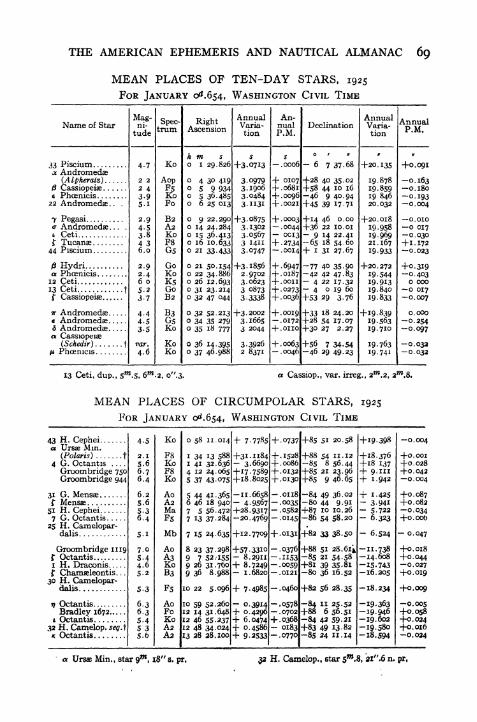
THE AMERICAN EPHEMERIS AND NAUTICAL ALMANAC 69
MEAN PLACES OF TEN-DAY STARS, 1925
FOR JANUARY 0^.654, WASHINGTON CIVIL TIME
13 Ceti, dup., , o".3- a Cassiop., var. irreg., 2W.2, 2m,8.
MEAN PLACES OF CIRCUMPOLAR STARS, 1925
FOR JANUARY 0^.654, WASHINGTON CIVIL TIME
43 H. Cepheia Ursae Mm.
(Polaris) t4 G. OctantisGroombridge 750Groombridge 944
31 G. Mensaef Mensae51 H. Cephei7 G. Octantis
25 H. Camelopar-dalis
Groombridge 1119f Octantisi H. Draconist Chamaeleontis. .
30 H. Camelopar-dalis
77 OctantisBradley 1672
t Octantis32 H. Camelop. segjK Octantis
4-5
2.1
5.66-76.4
6.2
5.65-36.4
7-05-44-65.2
6.36-35-45 35-6
Ko
F8KoF8Ko
AoAaMa
Mb
Ao
K3o
B3
AoFoKoA2A2
o 58 11.014 + 7.7785 +-0737 +85 51 20.58 +19.398 -0.004
I 34 13 .
I 41 32.6364 12 245 37 43-075
588 +31.1184V -3.6690 .
065 +17.7589 ++18.8025
'
5 44 41.3656 46 18 9407 5 56.4727 13 37-284
8 23 37.298 +579 7 52.1559 26 31.7609 36 8.988
10 22 5.096 + 7-4985
10 59 52.26012 14 31.648 +12 46 55-2372 48 34-024
13 28 28.100
II. 6- 4-9. .
+28.9317-20.4769
7 15 24.635 +12.7709 +.0131
. 33108.29118.72491.6820
0.4296+ 6.0474+ 0.4586+ 9-2533
+ .1528
+ .0086
.0132+ .0130
.0118
.0035
.0582
-.0145
-.0376-.1153-.0059
.0121
.0460
-.0578.0702
+ .0368- 0183-.0770
+88 54 u. 12
-85 8 56.44+85 21 23.96+85 9 46.65
-84 49 36.02-80 44 9-91+87 10 10.26-86 54 58-20
+82 33 38.50
+88 51 28.64-85 21 54-58+8l 39 35-8180 36 16.52
+82 56 28.35
-84 II 25.52+88 6 56.51-84 42 59-21+83 49 13-82-85 24 II. 14
+18.376+18 137+ 9-III+ 1-942
+ 1-425- 3-941- 5-7226.323
- 6.524
-11.738-14.608-15-743-16.205
-18.234
-19.363-19.946-19.602-19.580-18.594
+0.001+0.028+0.0420.004
+0.087+0.082-0.034+0.000
-0.047
+0.018+0.0440.027
+0.019
+0.009
0.005+0.058+0.024+0.0160.024
a Ursae Min., star 9m
, 18" s. pr, 32 H. Camelop., star 5W
.8, 21",6 n. pr,
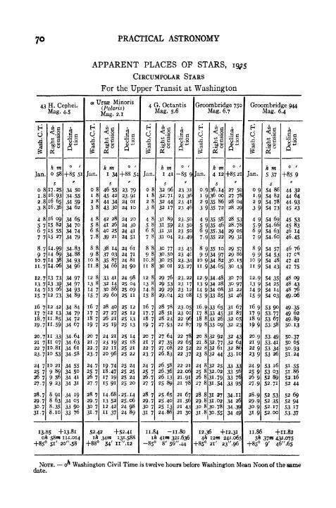
PRACTICAL ASTRONOMY
APPARENT PLACES OP STARS,
CIRCUMPOLAR STARS
For the Upper Transit at Washington
NOTE. o^ Washington Civil Time is twelve hours before Washington Mean Noon of the samedate.

THE AMERICAN EPHEMERIS AND NAUTICAL ALMANAC 71
APPARENT PLACES OF STARS, 1925
FOR THE UPPER TRANSIT AT WASHINGTON
WashingtonCivil Time
33 PisciumMag. 4-7
RightAscension
Declina-tion
a Andromeda;(Alpheratz)
Mag. 2 2
RightAscension
Declina-tion
j8 CassiopeiaeMag. 2.4
RightAscension
Declina-tion
e Phoanicis
Mag. 3-9
RightAscension
Declina-tion
.Jan.
Feb.
Mar.
Apr.
May
June
July
Aug.
Sept.
Oct.
Nov.
Dec.
7
10.720 7
30.696
19.6
1 6
ii 5
21.531 5
10.520 43010 420.3
30 3
9 319 329 2
9 2
19 2
29.28.118 i
28.1
7 o
17.027 o
716 9
2695-915-925 8
5.8
15.825 7
35 7
h mo i
28.841
28 53228 454
28.399
28 367 T
28 368 *|
28 402J4
28 473jjjl
28.583 '
28 733 *j>28 921
188
29 145
29 398
- 6 7
45 99 646 bo ;
47 13,j
47-49 2'47 71
2;
3247 7347 5947 20
46 5845 75
]
44 64 IV,43-31
^41 79
o 4
29-73429 58629 44429 31429 204
29.11829 063
29 046-29 07029 139 !^
%2M *
29 62520
;
29 87124
30.151 ts
29 678-29 97730 28530 59630 901
31 192 ,
31.463 ;
31 707 :
31 919 :
32.093 :
32.23132 32732 388
32 410-32 402
32.36232.30232 220
32 12732 021 i
31.908 .
31 795 :
31-684'
sl=30 12"
24174
26.51
s
i'326
21.2120 96
20.94-21 16
21.59
22.1722 8323 60
24 4025.22
26 01
7427-39
+28 40
38.63 .
2iS36 42
86 33
55
J724
34-9941
24.8120
239524 09
$3*33030 78S31-12031 45731 75
-5426.8228 433 ' 31
32.096 288 34-72" 'K *
!"! 37 I3
32 802
33-044 :
2412A7
^446 87
3334833 371-33 358
33 31533 24433.150 .
33-036 ;
32.908 J-
32.77032.625
JJ
43
71569457[I4 58
5835-^8
58 17
57 6956.90
h mo 5
9-620
8 436 g8$ '42
8 015-
8 0172
10.056543
1 O4I1 S$
370421
Ufia;
487498
3 827;
:4 OI94 1494 215
'4 l62112
4.0503 888
3 68
3 " 4323-152
248
12.8462 5252.198
+5843
8185 8
77 9679
.55
ss
70.24 ".
73-53 :
76.89 880.27
338
83 6186 .-82
89.83 :
-91
10055ioo 6s100 20 ^
h mo 5
s
35 oio
34-8II*
34.6283
34 4671Ui
34 333
34-232
34.169
34 147"34-17334 248 .
34 374I?8
7^ 3l8J '4
354
35 728}
ii
39 124I31
39 255 r\39.328 Jg
39 3463U g
39 228
39-I06J22
38 950 J|
S:SS?
S.ig~37-958
-46 9
61-3961.07
3-
60 28 ,7S
5906J
2^
57 43 ^55 43
23,53- 12 -_/j
44-79
41 7238. '_
35-58
295307
257
21 4320.32
19 67
19 80
i
194155
190216
35
42.3842.80
42-74
Mean Place
Sec a, Tan d
29.826
i. 006
37-68
0.107
30.419
1.140
35-02
+0.5479 934
I 927
70.16
+1-647
36 485 40-94
I 444 -1.041
+0.061
+0.40
+0.007
+0.01
+0.061 0.036
+0.40 +0.02
+0.062 o.no
+0.40 +0.02
+0.060
+0.40
+0.069
+0.03
NOTE, o" Washington Civil Time is twelve hours before Washington. Mean Noon of the samedate.

PRACTICAL ASTRONOMY
SUN, JANUARY 1925
NOTE. The Equation of Time is to be applied to the G. C. T. in accordance with the sign as
given,
oft Greenwich Civil Time is twelve hours before Greenwich Mean Noon of the same date.
SUN, 1925
FOR WASHINGTON APPAPENT NOON
NOTE. For mean time interval of semidiameter passing meridian, subtract os.i9 from theSidereal interval.
c^ Washington CM Time is twelve hours before Washington Mean Noon of the same date.

THE AMERICAN EPHEMERIS AND NAUTICAL ALMANAC 73
servation, by employing formulae and tables given for the pur-
pose in Part II of the Ephemeris.There are many star catalogues, some containing the positions
of a very large number of stars, but determined with rather in-
ferior accuracy; others contain a relatively small number of
stars, but whose places are determined with the greatest accu-
racy. Among the best of these latter may be mentioned the
Greenwich ten-year (and other) catalogues, and Boss' Catalogue. of 6188 stars for the epoch 1900. (Washington, 1910,)
For time and longitude observations, the list given in the
Ephemeris is sufficient, but for special kinds of work where the
observer has but a limited choice of positions, such as finding
latitude by Talcott's method, many other stars must be ob-
served.
42. Interpolation.
When taking data from the Ephemeris corresponding to any
given instant of Greenwich Civil Time, it will generally be neces-
sary to interpolate between the tabulated values of the function.
The usual method of interpolating, in trigonometric tables, for
instance, consists in assuming that the function varies uniformly
between two successive values in the table, and, if applied to the
Ephemeris, consists in giving the next preceding tabulated value
an increase (or decrease) directly proportional to the time elapsed
since the tabulated Greenwich time. If the function is repre-
sented graphically, it will be seen that this process places the
computed point on a chord of the function curve.
Since, however, the"variation per hour/' or differential co-
efficient of the function, is given opposite each value of the func-
tion it is simpler to employ this quantity as the rate of change of
the function and to multiply it by the time elapsed. An in-
spection of the diagram (Fig. 39) will show that this is also a
more accurate method than the former, provided we always
work from the nearer tabulated value; when the differential
coefficient is used the computed point lies on the tangent line,
and the curve is nearer to the tangent than to the chord for any

74 PRACTICAL ASTRONOMY
distance which is less than half the interval between tabulated
values.
To illustrate these methods of interpolating let it be assumed
that it is required to compute the sun's declination at 2ih Green-
wich Civil Time, Feb. i, 1925. The tabulated values for o*
(midnight) on Feb. i, and Feb. 2, are as follows:
Sun's declination Variation per hour
Feb. i, o* -17 18' o3 ".9 + 42"-i5
Feb. 2, o* 17 01 03 .2 + 42 .90
17 18*03'.'9
Greenwich Civil Time
FIG. 39
Feb,2
The given time, 21*, is nearer to midnight of Feb. 2 than it is
to midnight of Feb. i, so we must correct the value 17 01'
03". 2 by subtracting (algebraically) a correction equal to +42".9o
multiplied by 3", giving 17 03' iiff
.g. If we work from
the value for o*, Feb. i, we obtain 17 18' 03".9 42". 15 X21 =
17 03' i8".7. For the sake of comparison let us inter-
polate directly between the two tabulated values. This gives
-I7oi'o3".2 + A X i7'oo".7 = -i7o3'io".8. These
three values are shown on the tangents and chord respectively
in Fig. 39. It is clear that the first method gives a point nearer
to the function curve than either of the others'.

THE AMERICAN EPHEMERIS AND NAUTICAL ALMANAC 75
Whenever these methods are insufficient, as might be the
case when the tabular intervals are long, or the variations in
the"varia. per hour "
are rapid, it is possible to make a closer
approximation by interpolating between the given values of the
differential coefficients to obtain a more accurate value of the
rate of change for the particular interval employed. If we
imagine a parabola (Fig. 40) with its axis vertical and so placed
that it passes through the two given points, C and C', of the
^function curve and has the same slope at these points, then it is
FIG. 40. PARABOLA ky
obvious that this parabola must lie very close to the true curve
at all points between the tabulated values. By the following
process we may find a point 'exactly on the parabola and conse-
quently close to the true value. The second differential coeffi-
cient of the equation of the parabola is constant, and the slope
(dy/dx) may therefore be found for any desired point by simple
interpolation between the given values of dy/dx. If we deter-
mine the value of dy/dx for a point whose abscissa is half waybetween the tabulated time and the required time we obtain the
slope of a tangent line, rj1
', which is also the slope of a chord of

76 PRACTICAL ASTRONOMY
the parabola extending from the point representing the tabulated
value to the point representing the desired value;% for it may be
proved that for this particular parabola such a chord is exactly
parallel to the tangent (slope) so found. By finding the value
of the"varia. per hour
"corresponding to the middle of the
time interval over which we are interpolating, and employingthis in place of the given
"varia. per hour
" we place our point
exactly on the parabola, which must therefore be close to the
true point on the function curve. In the preceding example this
interpolation would be carried out as follows:
From o* Feb. 2 back to 21* Feb. i is 3* and the time at the
middle of this interval is 22* 30. Interpolating between
+42/;
.90 and +42". 15 we find that the rate of change for 22*
30ra
is +42".9o - X o".75= +42".86.
The declination is therefore
-I7oi'o3".2 -3 X 42".86 =
17 03' n".8.
This is the most accurate of the four values obtained.
As another example let it be required to find the right ascen-
sion of the moon at 9^ 40"* on May 18, 1925. The Ephemeris
gives the following data.
Green. Civ. Time Rt. Asc. Var. per Min.
9* o 29m
59^.56 2.0548
10* O 32 02 .80 2.0531
The Gr. Civ. Time at the middle of the interval from 9* to
9* 40 is 9* 20W,or one-third the way from the first to the sec-
ond tabulated value. The interpolated"variation per minute "
for this instant is 2.0542, one-third the way from 2.0548 to 2.0531.
The correction to the right ascension at 9* is 40 X 2^.0542=
82*. 168 and the corrected right ascension is therefore 0^31
2i*.73. If we interpolate from the right ascension at ioh using
a "var. per min." which is one-sixth the way from 2.0531
to 2.054$ we obtain the same result.
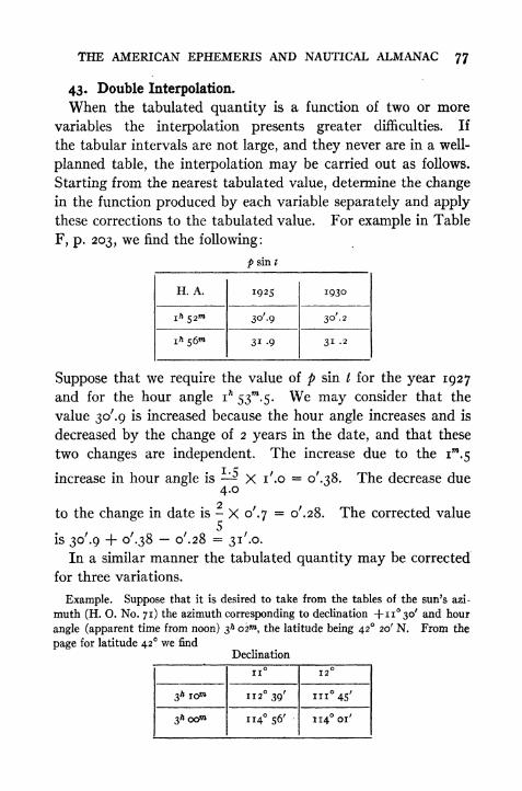
THE AMERICAN EPHEMERIS AND NAUTICAL ALMANAC 77
43. Double Interpolation.
When the tabulated quantity is a function of two or more
variables the interpolation presents greater difficulties. If
the tabular intervals are not large, and they never are in a well-
planned table, the interpolation may be carried out as follows.
Starting from the nearest tabulated value, determine the changein the function produced by each variable separately and apply
these corrections to the tabulated value. For example in Table
F, p. 203, we find the following:
p sin t
Suppose that we require the value of p sin t for the year 1927
and for the hour angle ih
53^.5. We may consider that the
value 30'.9 is increased because the hour angle increases and is
decreased by the change of 2 years in the date, and that these
two changes are independent. The increase due to the im.5
increase in hour angle is X i'.o = of
.^S. The decrease due4.02
to the change in date is - X o'.y= o'.28. The corrected value
is 30'.9 + o'.38 o'.28 =3i'.o.
In a similar manner the tabulated quantity may be corrected
for three variations.
Example. Suppose that it is desired to take from the tables of the sun's azi-
muth (H. O. No. 71) the azimuth corresponding to declination 4-n30/ and hour
angle (apparent time from noon) 3^ 02^, the latitude being 42 20' N. From the
page for latitude 42 we find
Declination

78 PRACTICAL ASTRONOMY
and from page for latitude 43 we find
Decimation
Selecting 114 56' as the value from which to start, we correct for the three varia-
tions as follows:
For latitude 42, decrease in iom time = 2 17'; decrease for 2 time = 27'.4.
For latitude 42, decrease for 1 of decimation = 55'; decrease for 30' of decli-
nation = 27 '.5. For 3^00"* increase for i of latitude =45'; increase for 20' of
latitude =15'.The corrected value is
114 56' 27'.4 27'. 5 + 15' = 114 i6'.i
For more general interpolation formulae the student is re-
ferred to Chauvenet's Spherical and Practical Astronomy, Doo-
little's Practical Astronomy, Hayford's Geodetic Astronomy,
and Rice's Theory and Practice of Interpolation.
Questions and Problems
1. Compute the sun's apparent declination when the local civil time is 15'*
(3* P.M.) Jan. 15, 1925, at a place 82 10' West of Greenwich (see p. 67).
2. Compute the right ascension of the mean sun +12^ at local o^ Jan. 10, 1925,
at a place 96 10' West of Greenwich (see p. 67).
3. Compute the equation of time for local apparent noon Jan. 30, 1925, at a
place 71 06' West of Greenwich.
4. Compute the apparent right ascensioji of the sun at G. C. T. i6> on Jan.
10, 1925, by the four different methods explained in Art. 42.
5. In Table F, p. 203, find by double interpolation the value of pf
sin t for / =
8* 42^.5 and for 1926.

CHAPTER VII
THE EARTH'S FIGURE CORRECTIONS TOOBSERVED ALTITUDES
44. The Earth's Figure.
The form of the earth's surface is approximately that of an
ellipsoid of revolution whose shortest axis is the axis of revolu-
tion. The actual figure departs slightly from that of the ellip-
soid but this difference is relatively small and may be neglectedin astronomical observations of the character considered in this
book. Each meridian may therefore be regarded as an ellipse,
and the equator and the parallels of latitude as perfect circles.
En fact the earth may, without appreciable error, be regardedis a sphere in such problems as arise in navigation and in field
astronomy with small instruments. The semi-major axis of
the meridian ellipse, or radius of the equator on the Clarke
(1866) Spheroid, used as the datum for Geodetic Surveys in
the United States, is 3963.27 statute miles, and the semi-minor
(polar) axis is 3949.83 miles in length. This difference of about
13 miles, or about one three-hundredth part, would only be
noticeable in precise work. The length of i of latitude at the
equator is 68.703 miles; at the pole it is 69.407 miles. The
length of i of the equator is 69.172 miles. The radius of a
sphere having the same volume as the ellipsoid is about 3958.9miles. On the Hayford (1909) spheroid the semi-major axis
is 3963.34 miles and the semi-minor is 3949.99 miles.
In locating points on the earth's surface by means of spherical
coordinates there are three kinds of latitude to be considered.
The latitude as found by direct astronomical observation is
dependent upon the direction of gravity as indicated by the
spirit levels of the instrument; this is distinguished as the
astronomical latitude. It is the angle which the vertical or
70
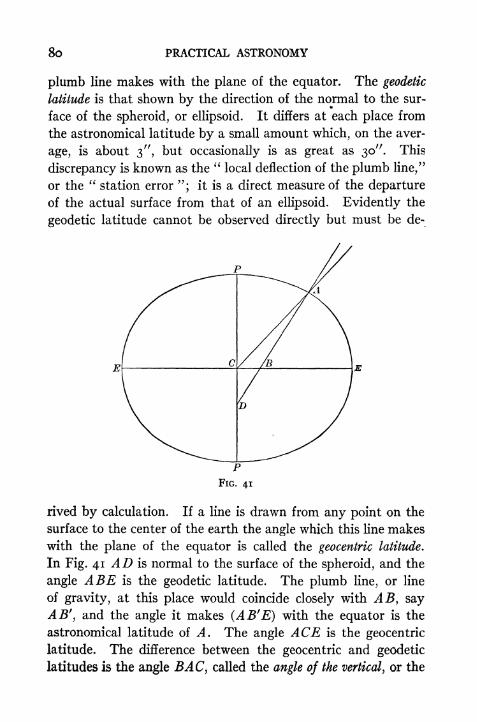
8o PRACTICAL ASTRONOMY
plumb line makes with the plane of the equator. The geodetic
latitude is that shown by the direction of the normal to the sur-
face of the spheroid, or ellipsoid. It differs at each place from
the astronomical latitude by a small amount which, on the aver-
age, is about 3", but occasionally is as great as 30". This
discrepancy is known as the"local deflection of the plumb line/'
or the"station error "; it is a direct measure of the departure
of the actual surface from that of an ellipsoid. Evidently the
geodetic latitude cannot be observed directly but must be de-
rived by calculation. If a line is drawn from any point on the
surface to the center of the earth the angle which this line makes
with the plane of the equator is called the geocentric latitude.
In Fig. 41 AD is normal to the surface of the spheroid, and the
angle ABE is the geodetic latitude. The plumb line, or line
of gravity, at this place would coincide closely with AB, say
AB', and the angle it makes (AB'E) with the equator is the
astronomical latitude of A. The angle ACE is the geocentric
latitude. The difference between the geocentric and geodetic
latitudes is the angle BA C, called the angle of the vertical, or the
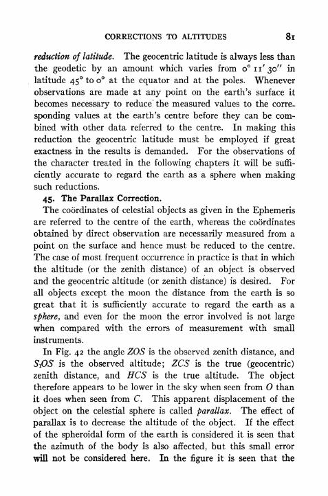
CORRECTIONS TO ALTITUDES 8l
reduction of latitude. The geocentric latitude is always less than
the geodetic by an amount which varies from o n' 30" in
latitude 45 to o at the equator and at the poles. Whenever
observations are made at any point on the earth's surface it
becomes necessary to reduce' the measured values to the corre-
sponding values at the earth's centre before they can be com-
bined with other data referred to the centre. In making this
reduction the geocentric latitude must be employed if great
exactness in the results is demanded. For the observations of
the character treated in the following chapters it will be suffi-
ciently accurate to regard the earth as a sphere when makingsuch reductions.
45. The Parallax Correction.
The coordinates of celestial objects as given in the Ephemerisare referred to the centre of the earth, whereas the coordinates
obtained by direct observation are necessarily measured from a
point on the surface and hence must be reduced to the centre.
The case of most frequent occurrence in practice is that in which
the altitude (or the zenith distance) of an object is observed
and the geocentric altitude (or zenith distance) is desired. For
all objects except the moon the distance from the earth is so
great that it is sufficiently accurate to regard the earth as a
sphere, and even for the moon the error involved is not large
when compared with the errors of measurement with small
instruments.
In Fig. 42 the angle ZOS is the observed zenith distance, and
SiOS is the observed altitude; ZCS is the true (geocentric)
zenith distance, and ECS is the true altitude. The object
therefore appears to be lower in the sky when seen from O than
it does when seen from C. This apparent displacement of the
object on the celestial sphere is called parallax. The effect of
parallax is to decrease the altitude of the object. If the effect
of the spheroidal form of the earth is considered it is seen that
the azimuth of the body is also affected, but this small error
will not be considered here. In the figure it is seen that the
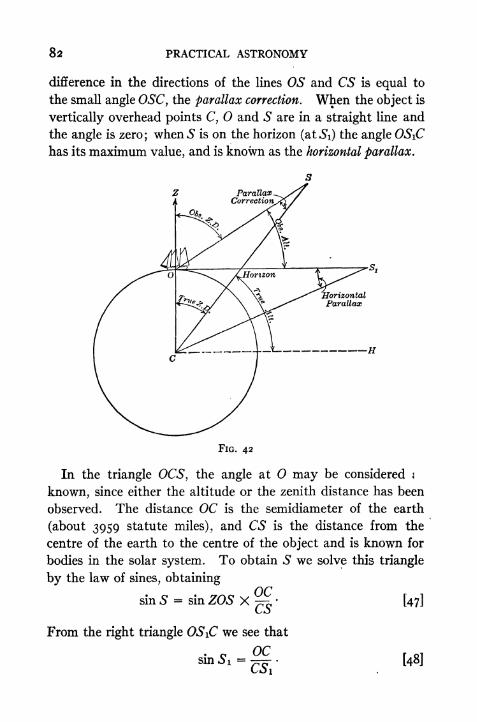
82 PRACTICAL ASTRONOMY
difference in the directions of the lines OS and CS is equal to
the small angle OSC, the parallax correction. When the object is
vertically overhead points C, and S are in a straight line and
the angle is zero; when S is on the horizon (at Si) the angle OSiC
has its maximum value, and is known as the horizontal parallax.
FIG. 42
In the triangle OCS, the angle at may be considered j
known, since either the altitude or the zenith distance has been
observed. The distance OC is the semidiameter of the earth
(about 3959 statute miles), and CS is the distance from the
centre of the earth to the centre of the object and is known for
bodies in the solar system. To obtain S we solve this triangle
by the law of sines, obtainingOC
sin S = sin ZOS XCS
From the right triangle OSiC we see that
OC=
C5i'sn [48]

CORRECTIONS TO ALTITUDES 83
The angle Si, or horizontal parallax, is given in the Ephemerisfor each object; we may therefore write,
sin S = sin Si sin ZOS [49]
or sin S = sin Si cos h. [50]
At this point it is to be observed that S and Si are very small
angles, about 9" for the sun and only i for the moon. Wemay therefore make a substitution of the angles themselves
(in radians) for their sines, since these are very nearly the same.*
This givesS (rad) = Si (rad) X cos h. [51]
To convert these angles expressed in radians into angles ex-
pressed in seconds f we substitute
S (rad) = S" X .000004848 . . .
and Si (rad) = S/' X .000004848 . . .,
the result being S" = S/' cos h, [52]
that is
parallax correction = horizontal parallax X cos h. [53]
* To show the error involved in this assumption express the sine as a series,
x3. x*
sm x x . . .
3 5
Since we have assumed that sin x = x the error is approximately equal to the next
term, For x = i the series is
sin i = 0.0174533 0.0000009 + o.ooooooo.
The error is therefore 9 in the seventh place of decimals and corresponds to about
o".i8. For angles less than i the error would be much smaller than this since
the term varies as the cube of the angle.
If, as is frequently done, the cosine of a small angle is replaced by i, the error
is that of the small terms of the series
*2,
x*COS X = I 1 . . . .
2 4For i this series becomes
cos i = i 0.00015234-.
The error therefore corresponds to an angle of 31".42, much larger than for the
first series.
t To reduce radians to seconds we may divide by arc i" (= 0.000004848137)
pr multiply by 206264.8,

84 PRACTICAL ASTRONOMY
As an example of the application of Equa. [53] let us computethe parallax correction of the sun on May i, 1925, when at an
apparent altitude of 50. From the Ephemeris the horizontal
parallax is found to be 8". 73. The correction is therefore
8".73 X cos 50 =s".6i
and the true altitude is 50 oo' O5".6i.
Table IV (A) gives approximate values of this correction for
the sun.
46. The Refraction Correction.
Astronomical refraction is the apparent displacement of a
celestial object due to the bending of the rays of light from the
object as they pass through the atmosphere. The angular
amount of this displacement is the refraction correction. Onaccount of the greater density of the atmosphere in the lower
portion the ray is bent into a curve, which is convex upward, and
FIG. 43
more sharply curved in the lower portion. In Fig. 43 the light
from the star S is curved from a down to 0, and the observer at
O sees the light apparently coming from S', along the line bO.
The star seems to him to be higher in the sky than it really is.
The difference between the direction of S and the direction of

CORRECTIONS TO ALTITUDES 85
S' is the correction which must be applied either to the apparentzenith distance or to the apparent altitude to obtain the true
zenith distance or the true altitude. A complete formula for
the refraction correction for any altitude, any temperature, and
any pressure, is rather complicated. For observations with a
small transit a simple formula will
answer provided its limitations are
understood. The simplest method
of deriving such a formula is to con-
sider that the refraction takes place
at the upper limit of the atmosphere
just as it would at the upper surface
of a plate of glass. This does not
represent the facts but its use maybe justified on the ground that the
total amount of refraction is the FIG. 44
same as though it did happen this
way. In Fig. 44 light from the star S is bent at 0' so that it
assumes the direction O'O and the observer sees the star appar-
ently at 5". ZO'S (= f') is the true zenith distance, ZO'S'
(= f) is the apparent zenith distance, and SO fSr
(= r) is the
refraction correction; then, from the figure,
r' = r + r. [54]
Whenever a ray of light passes from a rare to a dense medium (in
this case from vacuum into air) the bending takes place according
to the lawsin f
' = n sin f, [55]
where n is the index of refraction. For air this may be taken
as 1.00029. Substituting [54] in [55]
sin (f + r)= n sin f . [56]
Expanding the first member,
sin f cos r + cos f sin r = n sin f . [57]

86 PRACTICAL ASTRONOMY
Since r is a small angle, never greater than about o 34', we maywrite with small error (see note, p. 83).
sin r = r
and cos r = i
whencesin f + r cos f
= n sin f [58]
from which r = (n i) tan f [59]
being in radians.
To reduce r to minutes we divide by arc i'(= 0.0002909 . . .).
The final value of r is therefore approximately
r-ZSS&tot [6o](min) .00029
= tan [61]
= cot h. [62]
This formula is simple and convenient but must not be regarded
as showing the true law of refraction. The correction varies
nearly as the tangent of f from the zenith down to about f = 80
(h= 10), beyond which the formula is quite inaccurate. The
extent to which the formula departs from the true refraction
may be judged by a comparison with Table I, which gives the
values as calculated by a more accurate formula for a tempera-
ture of 50 F. and pressure 29.5 inches.
As an example of the use of this formula [62] and Table I
suppose that the lower edge of the sun has a (measured) altitude
of 31 30'. By formula [62] the value of r is i'.63, or i' 38".
The corrected altitude is therefore 31 28' 22". By Table I
the correction is i' 33", and the true altitude is 31 28' 27".
This difference of 5" is not very important in observations made
with an engineer's transit. Table I, or any good refraction
table, should be used when possible; the formula may be used
when a table of tangents is available and no refraction table is
at hand. For altitudes lower than 10 the formula should not
be considered reliable. More accurate refraction tables may be
CORRECTIONS TO ALTITUDES 87
found in any of the text books on Astronomy to which reference
has been made (p. 78). Table VIII, p. 233, gives the refraction
and parallax corrections for the sun.
As an aid in remembering the approximate amount of the
refraction it may be noted that at the zenith the refraction is
o; at 45 it is i'; at the horizon it is about o 34', or a little
larger than the sun's angular diameter. As a consequenceof the fact that the horizontal refraction is 34' while the sun's
diameter is 32', the entire disc of the sun is still visible (apparently
above the horizon) after it has actually set.
47. Semidiameters.
The discs of the sun and the moon are sensibly circular, and
their angular semidiameters are given for each day in the Ephem-eris. Since a measurement may be taken more accurately
to the edge, or limb, of the disc than to the centre, the altitude
of the centre is usually obtained by measuring the altitude of
the upper or lower edge and applying a correction equal to the
angular semidiameter. The angular semidiameter as seen bythe observer may differ from the tabulated value for two reasons.
When the object is above the horizon it is nearer to the observer
than it is to the centre of the earth, and the angular semidiameter
is therefore larger than that stated in the Ephemeris. Whenthe object is in the zenith it is about 4000 miles nearer the
observer than when it is in the horizon. The moon is about
240,000 miles distant from the earth, so that its apparent semi-
diameter is increased by about one sixtieth part or about 16".
Refraction is greater for a lower altitude than for a higher
altitude; the lower edge of the sun (or the moon) is always
apparently lifted more than the upper edge. This causes an
apparent contraction of the vertical diameter. This is most
noticeable when the sun or the moon is on the horizon, at which
time it appears elliptical in form. This contraction of the ver-
tical diameter has no effect on an observed altitude, however,
because the refraction correction applied is that corresponding
to the altitude of the edge observed; but the contraction must be
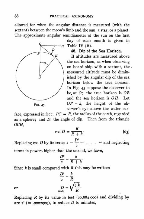
88 PRACTICAL ASTRONOMY
allowed for when the angular distance is measured (with the
sextant) between the moon's limb and the sun, a star, or a planet.
The approximate angular semidiameter of the sun on the first
day of each month is given in
Table IV (B).
48. Dip of the Sea Horizon.
If altitudes are measured above
the sea horizon, as when observing
on board ship with a sextant, the
measured altitude must be dimin-
ished by the angular dip of the sea
horizon below the true horizon.
In Fig. 45 suppose the observer to
be4at
;the true horizon is OB
and the sea horizon is OH. Let
OP =h, the height of the ob-
server's eye above the water sur-
face, expressed in feet; PC = R, the radius of the earth, regarded
as a sphere; and D, the angle of dip. Then from the triangle
OCH, nD = '
163]
FIG. 45
and neglectingReplacing cos D by its series i \- .
terms in powers higher than the second, we have,
D2 h
7"=R + h'
Since h is small compared with R this may be written
^! = A2 R _D-\/p.(rad)
T /C
Replacing U by its value in feet (20,884,000) and dividing byarc i' (
= .0002000), to reduce D to minutes,
CORRECTIONS TO ALTITUDES 89
x VI4 RV-2R
,- X arc i'2
= 1.064 Vh. [64]
This shows the amount of the dip with no allowance for refrac-
tion. But the horizon itself is apparently lifted by refraction
and the dip which affects an observed altitude is therefore less
*than that given by [64]. If the coefficient 1.064 is arbitrarily
taken as unity the formula is much nearer the truth and is very
simple, although the dip is still somewhat too large. It then
becomes
D f = VhJt. [65]
that is, tlie dip in minutes equals the square root of the height
in feet. Table IV (C), based upon a more accurate formula,
> will be seen to give smaller values.
49. Sequence of Corrections.
Strictly speaking, the corrections to the observed altitude
must be made in the following order: (i) Instrumental cor-
rections; (2) dip (if made at sea); (3) refraction; (4) semidi-
ameter; (5) parallax. In practice, however, it is seldom neces-
sary to follow this order exactly. The parallax correction for
the sun will not be appreciably different for the altitude of the
centre than it will for the altitude of the upper or lower edge;
if the altitude is low, however, it is important to employ the
'refraction correction corresponding to the edge observed, be-
cause .this may be sensibly different from that for the centre.
In navigation it is customary to combine all the corrections,
except the first, into a single correction given in a table whose
arguments are the"height of eye," and " observed altitude."
(See Bowditch, American Practical Navigator, Table 46.)
Problems
i. Compute the sun's mean horizontal parallax. The sun's mean distance is
92,900,000 miles; for the earth's radius see Art. 44. Compute the sun's parallax
at an altitude of 60
90 PRACTICAL ASTRONOMY
2. Compute the moon's mean horizontal parallax. The moon's mean distance
is 238,800 miles; for the earth's radius see Art. 44. Compute the moon's parallax
at an altitude of 45.
3. If the altitude of the sun's centre is 21 10' what is the parallax correction?
the corrected altitude?
4. If the observed altitude of a star is 15 30' what is the refraction correction?
the corrected altitude?
5. If the observed altitude of the lower edge of the sun is 27 41' on May ist
what is the true central altitude, corrected for refraction, parallax, and semidiameter?
6. The altitude of the sun's lower limb is observed at sea, Dec. i, and found
to be 18 24' 20". The index correction of the sextant is -f-i' 20". The height,
of eye is 30 feet. Compute the true altitude of the centre.

CHAPTER VIII
DESCRIPTION OF INSTRUMENTS
50, The Engineer's Transit.
The engineer's transit is an instrument for measuring hori-
zontal and vertical angles. For the purpose of discussing the
theory of the instrument it may be regarded as a telescopic line
of sight having motion about two axes at right angles to each
other, one vertical, the other horizontal. The line of sight is
determined by the optical centre of the object glass and the
intersection of two cross hairs* placed in its principal focus.
The vertical axis of the instrument coincides with the axes of
two spindles, one inside the other, each of which is attached to a
horizontal circular plate. The lower plate carries a graduatedcircle for measuring horizontal angles; the upper plate has two
verniers, on opposite sides, for reading angles on the circle.
On the top of the upper plate are two uprights, or standards,
supporting the horizontal axis to which the telescope is attached
and about which it rotates. At one end of the horizontal axis
is a vertical arc, or a circle, and on the standard is a vernier, in
contact with the circle, for reading the angles. The plates and
the horizontal axis are provided with clamps and slow-motion
screws to control the motion. On the upper plate are two spirit
levels for levelling the instrument, or, in other words, for makingthe vertical axis coincide with the direction of gravity.
The whole instrument may be made to turn in a horizontal
plane by a motion about the vertical axis, and the telescope maybe made to move in a vertical plane by a motion about the
tiorizontal axis. By means of a combination of these two
* Also called wires or threads; they are either made of spider threads, or plati-
mm wires, or are lines ruled upon glass.

92 PRACTICAL ASTRONOMY
motions, vertical and horizontal, the line of sight may be made
to point in any desired direction. The motion of the line of
sight in a horizontal plane is measured by the angle passed over)
by the index of the vernier along the graduated horizontal
circle. The angular motion in a vertical plane is measured bythe angle on the vertical arc indicated by the vernier attached
to the standard. The direction of the horizon is defined bymeans of a long spirit level attached to the telescope. Whenthe bubble is central the line of sight should lie in the plane of
the horizon. To be in perfect adjustment, (i) the axis of each
spirit level* should be in a plane at right angles to the vertical
axis; (2) the horizontal axis should be at right angles to the
vertical axis; (3) the line of sight should be at right angles to the
horizontal axis; (4) the axis of the telescope level should be
parallel to the line of sight, and (5) the vernier of the vertical
arc should read zero when the bubble is in the centre of the level
tube attached to the telescope. When the plate levels are-
brought to the centres of their tubes, and the lower plate is so
turned that the vernier reads o when the telescope points south,
then the vernier readings of the horizontal plate and the vertical
arc for any position of the telescope are coordinates of the
horizon system (Art. 12). If the horizontal circles are clampedin any position and the telescope is moved through a complete
revolution, the line of sight describes a vertical circle on the
celestial sphere. If the telescope is clamped at any altitude and
the instrument turned about the vertical axis, the line of sight
describes a cone and traces out on the sphere a parallel of alti-*
tude.
51. Elimination of Errors.
It is usually more difficult to measure an altitude accurately
with the transit than to measure a horizontal angle. While the
precision of horizontal angles may be increased by means of
repetitions, in measuring altitudes the precision cannot be<
* The axis of a level may be defined as a line tangent to the curve of the glass
tube at the point on the scale taken as the zero point, or at the centre of the tube.

DESCRIPTION OF INSTRUMENTS 93
increased by repeating the angles, owing to the construction of
the instrument. The vertical arc usually has but one vernier,
so that the eccentricity cannot be eliminated, and this vernier
often does not read as closely as the horizontal vernier. One
of the errors, which is likely to be large, but which may be elimi-
nated readily, is that known as the index error. The measured
altitude of an object may differ from the true reading for two
reasons: first, the zero of the vernier may not coincide with the
zero of the circle when the telescope bubble is in the centre of
its tube; second, the line of sight may not be horizontal when
the bubble is in the centre of the tube. The first part of this
error can be corrected by simply noting the vernier reading when
the bubble is central, and applying this as a correction to the
measured altitude. To eliminate the second part of the error
the altitude may be measured twice, once from the point on the
horizon directly beneath the object observed, and again from
the opposite point of the horizon. In other words, the instru-
ment may be reversed (180) about its vertical axis and the
vertical circle read in each position while the horizontal cross
hair of the telescope is sighting the object. The mean of the
two readings is free from the error in the sight line. Evidently
this method is practicable only with an instrument having a
complete vertical circle. If the reversal is made in this manner
the error due to non-adjustment of the vernier is eliminated at
the same time, so that it is unnecessary to make a special deter-
mination of it as described above. If the circle is graduated
in one direction, it will be necessary to subtract the second
reading from 180 and then take the mean between this result
and the first altitude. In the preceding description it is assumed
that the plate levels remain central during the reversal of the
instrument, indicating that the vertical axis is truly vertical.
If this is not the case, the instrument should be relevelled before
the second altitude is measured, the difference in the two altitude
readings in this case including all three errors. If it is not de-
sirable to relevel, the error of inclination of the vertical axis may

94 PRACTICAL ASTRONOMY
still be eliminated by reading the vernier of the vertical circle
in each of the two positions when the telescope bubble is central,
and applying these corrections separately. With an instru-
ment provided with a vertical arc only, it is essential that the axis
of the telescope bubble be made parallel to the line of sight, and
that the vertical axis be made truly vertical. To make the axis
vertical without adjusting the levels themselves, bring both
bubbles to the centres of their tubes, turn the instrument 180
in azimuth, and then bring each bubble half way back to the
centre by means of the levelling screws. When the axis is truly
vertical, each bubble should remain in the same part of its tube
in all azimuths. The axis may always be made vertical bymeans of the long bubble on the telescope; this is done by set-
ting it over one pair of levelling screws and centring it by means
of the tangent screw on the standard; the telescope is then
turned 180 about the vertical axis, and if the bubble moves from
the centre of its tube it is brought half way back by means of
the tangent screw, and then centred by means of the levelling
screws. This process should be repeated to test the accuracy
of the levelling; the telescope is then turned at .right angles
to the first position and the whole process repeated. This
method should always be used when the greatest precision is
desired, because the telescope bubble is much more sensitive
than the plate bubbles.
If the line of sight is not at right angles to the horizontal axis,
or if the horizontal axis is not perpendicular to the vertical axis,
the errors due to these two causes may be eliminated by com-
bining two sets of measurements, one in each position of the
instrument. If a horizontal angle is measured with the vertical
circle on the observer's right, and the same angle again observed
with the circle on his left, the mean of these two angles is free
from both these errors, because the two positions of the horizontal
axis are placed symmetrically about a true horizontal line,* and
*Strictly speaking, they are placed symmetrically about a perpendicular to
the vertical axis.
DESCRIPTION OF INSTRUMENTS 95
the two 'directions of the sight line are situated symmetricallyabout a true perpendicular to the rotation axis of the telescope.
If the horizontal axis is not perpendicular to the vertical axis the
line of sight describes a plane which is inclined to the true vertical
plane. In this case the sight line will not pass through the zenith,
and both horizontal and vertical angles will be in error. In
instruments intended for precise work a striding level is provided,
which may be set on the pivots of the horizontal axis. This
^enables the observer to level the axis or to measure its inclina-
tion without reference to the plate bubbles. The striding level
should be used in both the direct and the reversed position and
the mean of the two results used in order to eliminate the errors
of adjustment of the striding level itself. If the line of sight is
not perpendicular to the horizontal axis it will describe a cone
whose axis is the horizontal axis of the instrument. The line
of sight will in general not pass through the zenith, even though"the horizontal axis be in perfect adjustment. The instrument
must either be used in two positions, or else the cross hairs must
be adjusted. Except in large transits it is not usually practicable
to determine the amount of the error and allow for it.
52. Attachments to the Engineer's Transit. Reflector.
When making star observations with the transit it is necessary
to make some arrangement for illuminating the field of view.
Some transits are provided with a special shade tube into which
is fitted a mirror set at an angle of 45 and with the central
portion removed. By means of a lantern or a flash light held
at one side of the telescope light is reflected down the tube.
The cross hairs appear as dark lines against the bright field.
The stars can be seen through the opening in the centre of the
mirror. If no special shade tube is provided, it is a simple mat-
ter to make a substitute, either from a piece of bright tin or by
fastening^, piece of tracing cloth or oiled paper over the objec-
tive. A hole about f inch in diameter should be cut out, so
that the light from the star may enter the lens. If cloth or
paper is used, the flash light must be held so that the light is
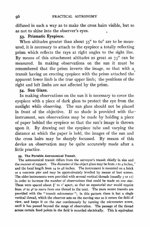
96 PRACTICAL ASTRONOMY
diffused in such a way as to make the cross hairs visible, but so
as not to shine into the observer's eyes.
53. Prismatic Eyepiece.
When altitudes greater than about 55 to 60 are to be meas-
ured, it is necessary to attach to the eyepiece a totally reflecting
prism which reflects the rays at right angles to the sight line.
By means of this attachment altitudes as great as 75 can be
measured. In making observations on the sun it must be
remembered that the prism inverts the image, so that witha^
transit having an erecting eyepiece with the prism attached the
apparent lower limb is the true upper limb; the positions of the
right and left limbs are not affected by the prism.
54. Sun Glass.
In making observations on the sun it is necessary to cover the
eyepiece with a piece of dark glass to protect the eye from the
sunlight while observing. The sun glass should not be placed
in front of the objective. If no shade is provided with the*
instrument, sun observations may be made by holding a piece
of paper behind the eyepiece so that the sun's image is thrown
upon it. By drawing out the eyepiece tube and varying the
distance at which the paper is held, the images of the sun and
the cross hairs may be sharply focussed. By means of this
device an observation may be quite accurately made after a
little practice.
55. The Portable Astronomical Transit.
The astronomical transit differs from the surveyor's transit chiefly in size and
the manner of support. The diameter of the object glass may be from 2 to 4 inches,fc
and the focal length from 24 to 48 inches. The instrument is mounted on a brick
or a concrete pier and may be approximately levelled by means of foot screws.
The older instruments were provided with several vertical threads (usually 5 or n)in order to increase the number of observations that could be made on one star.
These were spaced about J' to i' apart, so that an equatorial star would require
from 2* to 4s to move from one thread to the next. The more recent transits are
provided with the "transit micrometer "; in this pattern there is but a single
vertical thread, which the observer sets on the moving star as it enters the field of
view, and keeps it on the star continuously by turning the micrometer screw,
until it has passed beyond the range of observation. The passage of the thread
across certain fixed points in the field is recorded electrically. This is equivalent

DESCRIPTION OF INSTRUMENTS
FIG. 46. PORTABLE ASTRONOMICAL TRANSIT
From the catalogue of C. L. Berger & Sons

98 PRACTICAL ASTRONOMY
to observations on 20 vertical threads. The field is illuminated by electric lights
which are placed near the ends of the axis. The axis is perforated and a mirror
placed at the centre to reflect the light toward the eyepiece. *The motion of the
telescope in altitude is controlled by means of a cJamp and a tangent screw. The
azimuth motion is usually very small, just sufficient to permit of adjustment into
the plane of the meridian. The axis is levelled or its inclination is measured bymeans of a sensitive striding level applied to the pivots. The larger transits are
provided with a reversing apparatus.
The transit is used chiefly in the plane of the meridian for the direct determina-
tion of sidereal time by star transits. It may, however, be used in any vertical
plane, and for either time or latitude observations. The principal part of the
work consists in the determination of the instrumental errors and in calculating*
the corrections. The transit is in adjustment when the central thread is in a plane
through the optical centre perpendicular to the horizontal axis, and the vertical
threads are parallel to this plane. For observations of meridian transits this
plane must coincide with the plane of the meridian and the horizontal axis must
be truly horizontal.
The chief errors to be determined and allowed for are (i) the azimuth, or devia-
tion of the plane of collimation from the true meridian plane; (2) the inclination
of the horizontal axis to the horizon; and (3) collimation error, or error in the sight
line. Corrections are also applied for diurnal aberration of light, for the rate of the
timepiece, and for the inequality of the pivots. The corrections to reduce an ob-
served time to the true time of transit over the meridian are given by formulae
[66], [67], and [68]. These corrections would apply equally well to observations
made with an engineer's transit, and are of value to the surveyor chiefly in showing
him the relative magnitudes of the errors in different positions of the objects
observed. This may aid him in selecting stars even though no corrections are
actually applied for these errors.
The expressions for the corrections to any star are
Azimuth correction = a cos h sec 5 [66]
Level correction = b sin h sec 5 [67]
Collimation correction = c sec 5 [68]
in which a, b, and c are the constant errors in azimuth, level, and collimation, ^
respectively, expressed in seconds of time, and h is the altitude and B the declination
of the star. If the zenith distance is used instead of the altitude cos h and sin h
should be replaced by sin f and cos f respectively. These formulae may be easily
derived from spherical triangles. Formula [66] shows that for a star near the
zenith the azimuth correction will be small, even if a is large, because cos h is nearly
zero. Formula [67] shows that the level correction for a zenith star will be larger
than for a low star because sin h for the former is nearly unity. The azimuth error
a is found by comparing the results obtained from stars which culminate north of
the zenith with those obtained from south stars; if the plane of the instrument
lies to the east of south; stars south of the zenith will transit too early and those
north of the zenith will transit too late. From the observed times the angle maybe computed. The level error b is measured directly with the striding level, making

DESCRIPTION OF INSTRUMENTS 99
readings of both ends of the bubble, first in the direct, then in the reversed positions,
the angular value of one level division being known. The collimation error, c,
is found by comparing the results obtained with the axis in the direct position with
the results obtained with the axis in the reversed (end-for-end) position.
TABLE B. ERROR IN OBSERVED TIME OF TRANSIT (INSECONDS OF TIME) WHERE a, b OR c = i'.
Note. Use the bottom line for the collimation error.
From the preceding equations Table B has been computed. It is assumed
that the collimation plane is r', or 4*, out of the meridian (a = 4*); that the axis
is inclined i', or 4*, to the horizon (b 4*); and that the sight line is i', or 4*, to
the right or left of its true position (c = 4*). An examination of the table will
show that for low stars the azimuth corrections are large and the level corrections
are small, while for high stars the reverse is true. As an illustration of the use of
this table, suppose that the latitude is 42, and the star's declination is +30;and that a = i' (4*) and b = 2' (8*). The altitude of the star = 90
-(42 30)
78. The azimuth correction is therefore i s .o and the level correction is 2 X4*.6
= 9s . 2. If the line of sight were }' (or i*) in error the (collimation) correction
would be i*. 2. This shows that with a transit set closely in the meridian but with
a large possible error in the inclination of the axis, low stars will give better results
than high stars. This is likely to be the case with a surveyor's transit. If, how-
ever, the inclination of the axis can be accurately measured but the adjustmentinto the plane of the meridian is difficult, then the high stars will be preferable.
This is the condition more likely to prevail with the larger astronomical transits.
For the complete theory of the transit see Chauvenet's Spherical and Practical
Astronomy, Vol. II; the methods employed by the U. S. Coast and Geodetic
Survey are given in Special Publication; No. 14.

100 PRACTICAL ASTRONOMY
56. The Sextant.
The sextant is an instrument for measuring the angular dis-
tance between two objects, the angle always lying in the plane
through the two objects and the eye of the observer. It is
particularly useful at sea because it does not require a steady
support like the transit. It consists of a frame carrying a
graduated arc, AB, Fig. 47, about 60 long, and two mirrors 7
and H, the first one movable, the second one fixed. At the
centre of the arc, /, is a pivot on which swings an arm IV,
6 to 8 inches long. This arm carries a vernier V for reading the
angles on the arc AB. Upon this arm is placed the index glass
/. At H is the horizon glass. Both of these mirrors are set
so that their planes are perpendicular to the plane of the arc
AB, and so that when the vernier reads o the mirrors are parallel.
The half of the mirror H which is farthest from the frame is
unsilvered, so that objects may be viewed directly through the
glass. In the silvered portion other objects may be seen byreflection from the mirror 7 to the mirror H and thence to

DESCRIPTION OF INSTRUMENTS IOI
point 0. At a point near (on the line 110) is a telescope of|
low power for viewing the objects. Between the two mirrors
and also to the left of // are colored shade glasses to be used when
making observations on the sun. The principle of the instru-
ment is as follows : A ray of light coming from an object at
C is reflected by the mirror I to H, where it is again reflected
to O. The observer sees the image of C in apparent coincidence
with the object at D. The arc is so graduated that the reading
FIG. 48. SEXTANT
of the vernier gives directly the angle between OC and OD.
Drawing the perpendiculars FE and HE to the planes of the
two mirrors, it is seen that the angle between the mirrors is
a. j8. Prolonging CI and DH to meet at 0, it is seen that the
angle between the two objects is 2 a 2 0. The angle between
the mirrors is therefore half the angle between the objects that
appear to coincide. In order that the true angle may be read
directly from the arc each half degree is numbered as though it
were a degree. It will be seen that the position of the vertex
is variable, but since all objects observed are at great distances

102 PRACTICAL ASTRONOMY
the errors caused by changes in the position of O are always
negligible in astronomical observations.
The sextant is in adjustment when, (i) both mirrors are per-
pendicular to the plane of the arc; (2) the line of sight of the
telescope is parallel to the plane of the arc; and (3) the vernier
reads o when the mirrors are parallel to each other. If the
vernier does not read o when the double reflected image of a
point coincides with the object as seen directly, the index cor-
rection may be determined and applied as follows. Set the
vernier to read about 30' and place the shades in position for
sun observations. When the sun is sighted through the tele-
scope two images will be seen with their edges nearly in contact.
This contact should be made as nearly perfect as possible and
the vernier reading recorded. This should be repeated several
times to increase the accuracy. Then set the vernier about 30'
on the opposite side of the zero point and repeat the whole
operation, the reflected image of the sun now being on the op-
posite side of the direct image. If the shade glasses are of
different colors the contacts can be more precisely made. Half
the difference of the two (average) readings is the index correc-
tion. If the reading off the arc was the greater, the correction
is to be added to all readings of the vernier; if the greater reading
was on the arc, the correction must be subtracted.
In measuring an altitude of the sun above the sea horizon the
observer directs the telescope to the point on the horizon ver-
tically under the sun and then moves the index arm until the
reflected image of the sun comes into view. The sea horizon
can be seen through the plain glass and the sun is seen in the
mirror. The sun's lower limb is then set in contact with the
horizon line. In order to be certain that the angle is measured
to the point vertically beneath the sun, the instrument is tipped
slowly right and left, causing the sun's image to describe an arc.
This arc should be just tangent to the horizon. If at any point
the sun's limb goes below the horizon the altitude measured is too
great. The vernier reading corrected for index error and dip is
the apparent altitude of the lower limb above the true horizon.
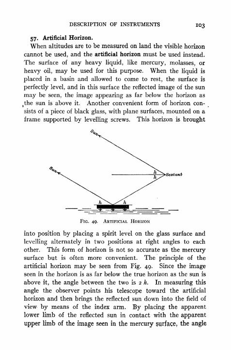
DESCRIPTION OF INSTRUMENTS 103
57. Artificial Horizon.
When altitudes are to be measured on land the visible horizon
cannot be used, and the artificial horizon must be used instead.
The surface of any heavy liquid, like mercury, molasses, or
heavy oil, may be used for this purpose. When the liquid is
placed in a basin and allowed to come to rest, the surface is
perfectly level, and in this surface the reflected image of the sun
may be seen, the image appearing as far below the horizon as
t
the sun is above it. Another convenient form of horizon con-
sists of a piece of black glass, with plane surfaces, mounted on a
frame supported by levelling screws. This horizon is brought
-Sextant
FIG. 49. ARTIFICIAL HORIZON
into position by placing a spirit level on the glass surface and
levelling alternately in two positions at right angles to each
other. This form of horizon is not so accurate as the mercurysurface but is often more convenient. The principle of the
artificial horizon may be seen from Fig. 49. Since the imageseen in the horizon is as far below the true horizon as the sun is
above it, the angle between the two is 2 h. In measuring this
angle the observer points his telescope toward the artificial
horizon and then brings the reflected sun down into the field of
view by means of the index arm. By placing the apparentlower limb of the reflected sun in contact with the apparent
upper limb of the image seen in the mercury surface, the angle

104 PRACTICAL ASTRONOMY
measured is twice the altitude of the sun's lower limb. The two
points in contact are really images of the same point. If the
telescope inverts the image, this statement applies to the upperlimb. The index correction must be applied before the angle is
divided by 2 to obtain the altitude. In using the mercury hori-
zon care must be taken to protect it from the wind; otherwise
small, waves on the mercury surface will blur and distort the
image. The horizon is usually provided with a roof-shapedcover having glass windows, but unless the glass has parallel
faces this introduces an error into the result. A good substitute
for the glass cover is one made of fine mosquito netting. This
will break the force of the wind if it is not blowing hard, and
does not introduce errors into the measurement.
58. Chronometer.
The chronometer is simply an accurately constructed watch
with a special form of escapement. Chronometers may be
regulated for either sidereal or mean time. The beat is usually
a half second. Those designed to register the time on chrono-
graphs are arranged to break an electric circuit at the end of
every second or every two seconds. The 6oth second is dis-
tinguished either by the omission of the break at the previous
second, or by an extra break, according to the construction of the
chronometer. Chronometers are usually hung in gimbals to
keep them level at all times; this is invariably done when theyare taken to sea. It is important that the temperature of the
chronometer should be kept as nearly uniform as possible, be-
cause fluctuation in temperature is the greatest source of error.
Two chronometers of the same kind cannot be directly com-
pared with great accuracy, os.i or os
.2 being about as close as
the difference can be estimated. But a sidereal and a solar chro-
nometer can easily be compared within a few hundredths of a
second. On account of the gain of the sidereal on the solar
chronometer, the beats of the two will coincide once in about
every 3 03*. If the two are compared at the instant when the
beats are apparently coincident, then it is only necessary to
note the seconds and half seconds, as there are no fractions to
DESCRIPTION OF INSTRUMENTS 105
be estimated. By making several comparisons and reducing
them to some common instant of time it is readily seen that
the comparison is correct within a few hundredths of a second.
The accuracy of the comparison depends upon the fact that the
ear can detect a much smaller interval between the two beats
than can possibly be estimated when comparing two chronome-
ters whose beats do not coincide.
59. Chronograph.The chronograph is an instrument for recording the time kept by a chronometer
and also any observations the times of which it is desired to determine. The paperon which the record is made is wrapped around a cylinder which is revolved by a
clock mechanism at a uniform rate, usually once per minute. The pen which makes
the record is placed on the armature of an electromagnet which is mounted on a
carriage drawn horizontally by a long screw turned by the same mechanism. The
mark made by the pen runs spirally around the drum, which results in a series of
straight parallel lines when the paper is laid flat. The chronometer is connected
electrically with the electromagnet and records the seconds by making notches in
the line corresponding to the breaks in the circuit, one centimeter being equivalent
, to one second. Observations are recorded by the observer by pressing a telegraph
key, which also breaks (or makes) the chronograph circuit and makes a mark on
the record sheet. If the transit micrometer is used the passage of the vertical
thread over fixed points in the field is automatically recorded on the chronograph.The circuit with which the transit micrometer is connected operates on the
" make "
instead of the" break "
circuit. When the paper is laid flat the time appears as
a linear distance on the sheet and may be scaled off directly with a scale graduated
to fit the spacing of the minutes and seconds of the chronograph.
60. The Zenith Telescope.
The Zenith Telescope is an instrument designed for making observations for
latitude by a special method known as the Harrebow-Taicott method. The in-
strument consists of a telescope attached to one end of a short horizontal axis
which is mounted on the top of a vertical axis. About these two axes the telescope
has motions in the vertical and horizontal planes like a transit. A counterpoise
is placed at the other end of the horizontal axis to balance the instrument. The
essential parts of the instrument are (i) a micrometer placed in the focal plane of
the eyepiece for measuring small angles in the vertical plane, and (2) a sensitive
spirit level attached to the vernier arm of a small vertical circle on the telescope
tube for measuring small. changes in the inclination of the telescope. The tele-
scope is ordinarily used in the plane of the meridian, but may be used in any ver-
tical plane.
The zenith telescope is put in adjustment by placing the line of sight in a plane
perpendicular to the horizontal axis, the micrometer thread horizontal, the hori-
zontal axis perpendicular to the vertical axis, and the base levels in planes per-
pendicular to the vertical axis. For placing the line of sight in the plane of the
meridian there are two adjustable stops which must be so placed and clamped

io6 PRACTICAL ASTRONOMY
that the telescope may be quickly turned about the vertical axis from the north
to the south meridian, or vice versa, and clamped in the plane of the meridian.
The observations consist in measuring with
the micrometer the difference in zenith dis-
tance of two stars, one north of the zenith,
one south of it, which culminate within a few
minutes of each other, and in reading the scale
readings of the ends of the bubble on the lati-
tude level. The two stars must have zenith
distances such that they pass the meridian
within the range of the micrometer.
A diagram of the instrument in the two*
positions is shown in Fig. 50. The inclination
of the telescope to the latitude level is not
changed during the observation. Any change
in the inclination of the telescope to the ver-
tical is measured by the latitude level and
may be allowed for in the calculation. The
principle involved in this method may be seen
from Fig. 51. From the zenith distance of
the star Ss the latitude would beFIG. 50. THE ZENITH TELESCOPE
and from the star S*
The mean of the two gives
4-[69]
showing that the latitude is the mean of the two decimations corrected by a small
angle equal to half the difference of the zenith distances. The declinations are
furnished by the star catalogues,
and the difference of zenith dis-
tance is measured accurately
with the micrometer. The com-
plete formula would include a
term for the level correction and
one for the small differential re-
fraction. This method gives
the most precise latitudes that
can be determined with a field
instrument.
It is possible for the surveyor
to employ this same principle if his transit is provided with a gradienter screw andan accurate level. The gradienter screw takes the place of the micrometer. Alevel may be attached to the end of the horizontal axis and made to do the workof a latitude level.
FIG. 51

DESCRIPTION OF INSTRUMENTS 107
ui. Suggestions about Observing with Small Instruments.
The instrument used for making such observations as are
described in this book will usually be either the engineer's transit
or the sextant. In using the transit care must be taken to give
the tripod a firm support. If the ground is shaky three pegs
may be driven and the points of the tripods set in depressions
in the top of the pegs. It is well to set the transit in position
some time before the observations are to be begun; this allows
the instrument to assume the temperature of the air and the
tripod legs to come to a firm bearing on the ground. The
observer should handle the instrument with great care, par-
ticularly during night observations, when the instrument is
likely to be accidentally disturbed. In reading angles at night
it is important to hold the light in such a position that the
graduations on the circle are plainly visible and may be viewed
along the lines of graduation, not obliquely. By changing the
position of the flash light and the position of the eye it will be
found that the reading varies by larger amounts than would be
expected when reading in the daylight. Care should be taken
not to touch the graduated silver circles, as they soon become
tarnished. If a lantern is used it should be held so as to heat the
instrument as little as possible, and so as not to shine into the
observer's eyes. Time may be saved and mistakes avoided if
the program of observations is laid out beforehand, so that the
observer knows just what is to be done and the proper order of
the different steps. The observations should be arranged so as
to eliminate instrumental errors by reversing the instrument;
but if this is not practicable, then the instrument must be put in
good adjustment. The index correction should be determined
and applied, unless it can be eliminated by the method of ob-
serving.
In observations for time it will often be necessary to use an
ordinary watch. If there are two observers, one can read the
time while the other makes the observations. If a chronometer
is used, one observer may easily do the work of both, and at the
same time increase the accuracy. In making observations by

io8 PRACTICAL ASTRONOMY
this method (called the"eye and ear method ") the observer
looks at the chronometer, notes the reading at some instant, sayat the beginning of some minute, and, listening to the half-second
beats, carries along the count mentally and without looking at
the chronometer. In this way he can note the second and
estimate the fraction without taking his attention from the star
and cross hair. After making his observation he may check his
count by again looking at the chronometer to see if the two
agree. After a little practice this method can be used easily
and accurately. In using a watch it is possible for one observer
to make the observations and also note the time, but it cannot
be done with any such precision as with the chronometer, be-
cause on account of the rapidity of the ticks (5 per second),
the observer cannot count the seconds mentally. The observer
must in this case look quickly at his watch and make an allow-
ance, if it appears necessary, for the time lost in looking up and
taking the reading.
62. Errors in Horizontal Angles.
When measuring horizontal angles with a transit, such, for
example, as in determining the azimuth of a line from the pole-
star, any error in the po-
sition of the sight line,
or any inclination of the
horizontal axis will be
found to produce a large
error in the result, on
account of the high alti-
tude of the star. In
ordinary surveying these
errors are so small that
they are neglected, but
in astronomical work
they must either be eliminated or determined and allowed for
in the calculations.
In Fig. 52 ZH is the circle traced out by the true collimation
axis, and the dotted circle is that traced by the actual line of
H
FIG. 52. LINE OF SIGHT IN ERROR(CROSS-HAIR OUT)

DESCRIPTION OF INSTRUMENTS
tan 4
FIG, 53. PLATE LEVELS ADJUSTEDBUBBLES NOT CENTRED
sight, which is in error by the small angle c. The effect of this
on the direction of a star S is the angle SZH.
In -Fig. 53 the vertical
axis is not truly vertical,
but is inclined by the
angle i owing to poor
levelling. This produces
an error in the direction
of point P which is equal
to the angle HZ'P. If
the vertical axis is truly
vertical but the horizon-
tal axis is inclined to the
horizon by the angle i,
owing to lack of adjustment, the error in the direction of the
point (S) is the same in amount and equal to the angle
HiZ// 2 in Fig. 54.
Problems
1. Show that if the sight
line makes an angle c with the
perpendicular to the horizontal
axis (Fig. 52) the horizontal
angle between two points is in
error by the angle
c sec hf
c sec /?",
where hr
and h" are the alti-
tudes of the two points.
2. Show that if the hori-
zontal axis is inclined to the
horizon by the angle i (Figs. 53
and 54) the effect upon the azimuth of the sight line is i tan hyand that an
angle is in error byi (tan V - tan h"),
where h' and h" are the altitudes of the points.
FIG. 54. PLATE LEVELS CORRECT HORIZONTALAxis OUT OF ADJUSTMENT

CHAPTER IX
THE CONSTELLATIONS
63. The Constellations.
A study of the constellations is not really a part of the subject ,
of Practical Astronomy, and in much of the routine work of'
observing it would be of comparatively little value, since the
stars used can be identified by means of their coordinates and a
knowledge of their positions in the constellations is not essential.
If an observer has placed his transit in the meridian and knows
approximately his latitude and the local time, he can identify
stars crossing the meridian by means of the times and the alti-
tudes at which they culminate. But in making occasional
observations with small instruments, and where much of the
astronomical data is not known to the observer at the time, some
knowledge of the stars is necessary. When a surveyor is be-
ginning a series of observations in a new place and has no accu-
rate knowledge of his position nor the position of the celestial
sphere at the moment, he must be able to identify certain stars
in order to make approximate determinations of the quantities
sought.
64. Method of Naming Stars.
The whole sky is divided in an arbitrary manner into irregular
areas, all of the stars in any one area being called a constellation
and given a special name. The individual stars in any constel-
lation are usually distinguished by a name, a Greek letter,* or
a number. The letters are usually assigned in the order of
brightness of the stars, a being the brightest, ft the next, and so
on. A star is named by stating first its letter and then the nameof the constellation in the (Latin) genitive form. For instance,
* The Greek alphabet is given on p. 190. %
no

THE CONSTELLATIONS III
in the constellation Ursa Minor the star a is called a Ursa
Minoris; the star Vega in the constellation Lyra is called
a Lyra. When two stars are very close together and have
been given the same letter, they are often distinguished by the
numbers i, 2, etc., written above the letter, as, for example,o? Capricorni, meaning that the star passes the meridian after
a1Capricorni.
65. Magnitudes.
The brightness of stars is shown on a numerical scale by their
magnitudes. A star having a magnitude i is brighter than one
having a magnitude 2. On the scale of magnitudes in use a few
of the brightest stars have fractional or negative magnitudes.
Stars of the fifth magnitude are visible to the naked eye only
under favorable conditions. Below the fifth magnitude a tele-
scope is usually necessary to render the star visible.
66. Constellations Near the Pole.
The stars of the greatest importance to the surveyor are those
near the pole. In the northern hemisphere the pole is marked
by a second-magnitude star, called the polestar, Polaris, or
a Ursa Minoris, which is about i 06' distant from the pole
at the present time (1925). This distance is now decreasing
at the rate of about one-third of a minute per year, so that for
several centuries this star will be close to the celestial north pole.
On the same side of the pole as Polaris, but much farther from
it, is a constellation called Cassiopeia, the five brightest stars
%of which form a rather unsymmetrical letter W (Fig. 55). The
lower left-hand star of this constellation, the one at the bottom
of the first stroke of the W, is called b, and is of importance to
the surveyor because it is very nearly on the hour circle passing
through Polaris and the pole; in other words its right ascension
is nearly the same as that of Polaris. On the opposite side of
the pole from Cassiopeia is Ursa Major, or the great dipper, a
rather conspicuous constellation. The star f, which is at the
bend in the dipper handle, is also nearly on the same hour circle
as Polaris and 8 Cassiopeia. If a line be drawn on the sphere

112 PRACTICAL ASTRONOMY
between d Cassiopeia and f Ursa Majoris, it wilj pass nearly
through Polaris and the pole, and will show at once the position
of Polaris in its diurnal circle. The two stars in the bowl of,
the great dipper on the side farthest from the handle are in a
line which, if prolonged, would pass near to Polaris. These
stars are therefore called the pointers and may be used to find
the polestar. There is no other star near Polaris which is
likely to be confused with it. Another star which should be
remembered is ft Cassiopeia, the one at the upper right-hand*
corner of the W. Its right ascension is very nearly oh and
therefore the hour circle through it passes nearly through the
equinox. It is possible then, by simply glancing at ft Cassiopeia
and the polestar, to estimate approximately the local sidereal
time. When ft Cassiopeia is vertically above the polestar it
is nearly oh sidereal time; when the star is below the polestar
it is i2hsidereal time; half way between these positions, left and
right, it is 6h and i8
h, respectively. In intermediate positions
1
the hour angle of the star (= sidereal time) may be roughly
estimated.
67. Constellations Near the Equator.
The principal constellations within 45 of the equator are
shown in Figs. 56 to 58. Hour circles are drawn for each hour
of R. A. and parallels for each 10 of declination. The approxi-
mate declination and right ascension of a star may be obtained
by scaling the coordinates from the chart. The position of the
ecliptic, or sun's path in the sky, is shown as a curved line. The,
moon and the planets are always found near this circle because
the planes of their orbits have only a small inclination to the
earth's orbit. A belt extending about 8 each side of the ecliptic
is called the Zodiac, and all the members of the solar systemwill always be found within this belt. The constellations along
this belt, and which have given the names to the twelve "signs
of the Zodiac/7
are Aries, Taurus, Gemini, Cancer, Leo, Virgo,
Libra, Scorpio, Sagittarius, Capricornus, Aquarius, and Pisces.
These constellations were named many centuries ago, and the


THE CONSTELLATIONS 113
names have been retained, both for the constellations themselves
and also for the positions in the ecliptic which they occupied at
that time. But on account of the continuous westward motion
of the equinox, the"signs
" no longer correspond to the con-
stellations of the same name. For example, the sign of Aries
extends from the equinoctial point to a point on the ecliptic
30 eastward, but the constellation actually occupying this
space at present is Pisces. In Figs. 56 to 58 the constellations' are shown as seen by an observer on the earth, not as they would
appear on a celestial globe. On account of the form of pro-
jection used in these maps there is some distortion, but if the
observer faces south and holds the page up at an altitude equal
to his co-latitude, the map represents the constellations very
nearly as they will appear to him. The portion of the map to be
used in any month is that marked with the name of the month
at the top; for example, the stars under the word "February
"
are those passing the meridian in the middle of February at
about 9 P.M. For other hours in the evening the stars on the
meridian will be those at a corresponding distance right or left,
according as the time is earlier or later than 9 P.M. The approxi-
mate right ascension of a point on the meridian may be found at
any time as follows: First compute the R. A. of the sun by
allowing 2h
per month, or more nearly 4 per day for every;
day since March 23, remembering that the R. A. of the sun is
always increasing. Add this R. A. + 12* to the local civil time
and the result is the sidereal time or right ascension of a star
on the meridian.
Example. On October 10 the R. A. of the sun is 6 X 2h + 17 X
4m = 13*08. The R. A. of sun + i2Ms 25* o8m
,or i* o8w.
At 9* P.M. the local civil time is 21*. ih oSm + 21* = 22* 08**.
A star having a R. A. of 22* o8m would therefore be close to the
meridian at 9 P.M.
Fig. 59 shows the stars about the south celestial pole. There,
is no bright star near the south pole, so that the convenient
methods of determining the meridian by observations on the
polestar are not practicable in the southern hemisphere.

114 PRACTICAL ASTRONOMY
68. The Planets.
In using the star maps, the student should be on the lookout
for planets. These cannot be placed on the maps because their
positions are rapidly changing. If a bright star is seen near the
ecliptic, and its position does not correspond to that of a star
on the map, it is a planet. The planet Venus is very bright and
is never very far east or west of the sun; it will therefore be
seen a little before sunrise or a little after sunset. Mars, Jupi-
ter, and Saturn move in orbits which are outside of that of the
earth and therefore appear to us to make a complete circuit of
the heavens. Mars makes one revolution around the sun in
i year 10 months, Jupiter in about 12 years, and Saturn in
29! years. Jupiter is the brightest, and when looked at througha small telescope shows a disc like that of the full moon; four
satellites can usually be seen lying nearly in a straight line.
Saturn is not as large as Jupiter, but in a telescope of moderate
power its rings can be distinguished; in a low-power telescope
the planet appears to be elliptical in form. Mars is reddish in
color and shows a disc.

CHAPTER X
OBSERVATIONS FOR LATITUDE
IN this chapter and the three immediately following are giventhe more common methods of determining latitude, time, longi-
tude, and azimuth with small instruments. Those which are
simple and direct are printed in large type, and may be used for
a short course in the subject. Following these are given, in
smaller type, several methods which, although less simple, are veryuseful to the engineer; these methods require a knowledge of
other data which the engineer must obtain by observation, and
are therefore better adapted to a more extended course of study.
69. Latitude by a Circumpolar Star at Culmination.
This method may be used with any circumpolar star, but
Polaris is the best one to use, when it is practicable to do so,
because it is of the second magnitude, while all of the other
close circumpolars are quite faint. The observation consists
in measuring the altitude of the star when it is a maximum or a
minimum, or, in other words, when it is on the observer's me-
ridian. This altitude may be obtained by trial, and it is not
necessary to know the exact instant when the star is on the
meridian. The approximate time when the star is at culmina-
tion may be obtained from Table V or by Art. 34 and Equa. [45].
It is not necessary to know the time with accuracy, but it will
save unnecessary waiting if the time is known approximately.
In the absence of any definite knowledge of the time of culmina-
tion, the position of the pole star with respect to the meridian maybe estimated by noting the positions of the constellations. When& Cassiopeia is directly above or below Polaris the latter is at
upper or lower culmination. The observation should be begunsome time before one of these positions is reached. The hori-
"5
n6 PRACTICAL ASTRONOMY
zontal cross hair of the transit should be set on the star* and the
motion of the star followed by means of the tangent screw of the
horizontal axis. When the desired maximum or minimum is
reached the vertical arc is read. The index correction should
then be determined. If the instrument has a complete vertical
circle and the time of culmination is known approximately, it
will be well to eliminate instrumental errors by taking a second
altitude with the instrument reversed, provided that neither
observation is made more than 4 or 5m from the time of culmi-
nation. If the star is a faint one, and therefore difficult to find,
it may be necessary to compute its approximate altitude (using
the best known value for the latitude) and set off this altitude
on the vertical arc. The star may be found by moving the
telescope slowly right and left until the star comes into the field
of view. Polaris can usually be found in this manner some time
before dark, when it cannot be seen with the unaided eye. It
is especially important to focus the telescope carefully before
attempting to find the star, for the slightest error of focus mayrender the star invisible. The focus may be adjusted by look-
ing at a distant terrestrial object or, better still, by sighting .at
the moon or at a planet if one is visible. If observations are to
be made frequently with a surveyor's transit, it is well to have
a reference mark scratched on the telescope tube, so that the
objective may be set at once at the proper focus.
The latitude is computed from Equa. [3] or [4], p. 31. Thetrue altitude h is derived from the reading of the vertical circle
by applying the index correction with proper sign and then
subtracting the refraction correction (Table I). The polar
distance is found by taking from the Ephemeris (Table of
Circumpolar Stars) the apparent declination of the star and
subtracting this from 90.
* The image of a star would be practically a point of light in a perfect telescope,
but, owing to the imperfections in the corrections for spherical and chromatic
aberration, the image is irregular in shape and has an appreciable width. The
image of the star should be bisected with the horizontal cross hair,

OBSERVATIONS FOR LATITUDE 117
Example i.
Observed altitude of Polaris at upper culmination = 43 37';
index correction = +30"; declination = +88 44' 35".
Vertical circle = 43 37' oo"Index correction = +30Observed altitude = 43 37 30Refraction correction =_
i oo
True altitude = 43 36 30Polar distance =
__i 15 _2^
Latitude =~42~2i'~os"
Since the vertical circle reads only to i' the resulting value for the
latitude must be considered as reliable only to the nearest i'.
Example 2.
Observed altitude of 51 Cephei at lower culmination = 39
33' 30"; index correction = o"; declination = + 87 n' 25".
Observed altitude = 39 33' 30"Refraction correction = i 09
True altitude 39 3 2 2I
Polar distance ==2^48 35^
Latitude == 4~2~2o' 56"
70. Latitude by Altitude of Sun at Noon.
The altitude of the sun at noon (meridian passage) may be
determined by placing the line of sight of the transit in the plane
of the meridian and observing the altitude of the upper or lower
limb of the sun when it is on the vertical cross hair. The watch
time at which the sun will pass the meridian may be computed
by converting i2h
local apparent time into Standard or local
mean time (whichever is used) as shown in Arts. 28 and 32.
Usually the direction of the meridian is not known, so the maxi-
mum altitude of the sun is observed and assumed to be the same
as the meridian altitude. On account of the sun's changing
declination the maximum altitude is not quite the same as the
meridian altitude; the difference is quite small, however, usually
a fraction of a second, and may be entirely neglected for obser-
vations made with the engineer's transit or the sextant. The
maximum altitude of the upper or lower limb is found by trial,

Il8 PRACTICAL ASTRONOMY
the horizontal cross hair being kept tangent to the limb as long
as it continues to rise. When the observed limb begins to dropbelow the cross hair the altitude is read from the vertical arc
and the index correction is determined. The true altitude of
the centre of the sun is then found by applying the corrections for
index error, refraction, semidiameter, and parallax. In order
to compute the latitude it is necessary to know the sun's declina-
tion at the instant the altitude was taken. If the longitude of
the place is known the sun's declination may be corrected as
follows: If the Greenwich Time or the Standard Time is noted
at the instant of the observation the number of hours since
o* Gr. Civ. Time is known at once. If the time has not been
observed it may be derived from the known longitude of the
place. Since the sun is on the meridian the local apparent time
is 12*. Adding the longitude we obtain the Gr. App. Time.
This is converted into Gr. Civil Time by subtracting the equa-tion of time. The declination is then corrected by an amount
equal to the"variation per hour "
multiplied by the hours of
the Gr. Civ. Time. The time need not be computed with great
accuracy since an error of im
will never cause an error greater
than i" in the computed declination. The latitude is com-
puted by applying equation [i] or its equivalent.
Example i. Observed maximum altitude of the sun's lower limb, Jan. 15, 1925,= 26 15' (sun south of zenith); index correction, -f-i'; longitude 7io6'W.;sun's declination Jan. 15 at o^ Greenwich Civil Time = 21 15' ig
/f.4, variation
per hour, -|~26".89; Jan. 16, 21 04' 2i".g; variation per hour, + 27".9o; equa-tion of time, ~gm 17
s; semidiameter, 16' if'.53.
Observed altitude = 26 15' Loc. App. Time = 12*
Index correction -f-i' Longitude = 4h 44m 24s
26 1 6' Gr. App. Time = 16^44 24*
Refraction ~i-9 Equa. Time = 9 17
7 Gr. Civ. Time = 16" 53 41*Semidiameter
Parallax -f-.i Decl. at o = -21 04' 21^.9
263o'.s -f-27".9o X 7h-i = 3 18 *
Declination 21 07.7 Corrected Decl. = 21 of 4o".o
Co-latitude 47 38'.2
Latitude 42 ai',8
Example 2. Observed maximum altitude of sun's lower limb June i, 1925 =44 48' 30" bearing north; index correction = o"; Gr. Civil Time = 14* 50"* 12*,

OBSERVATIONS FOR LATITUDE
declination of sun at o>, G. C. T., = +21 57' 13". 7; variation per hour, +21".n;semidiameter, 15' 48^.05 .
Observed altitude 44 48' 30"Refraction 57
Decl. at o* = +21 57' 13".?+ 2i".u X i4*-84 = +5 13 -3
Corrected Decl. +22 02' 27^.0
71. By the Meridian Altitude of a Southern* Star.
The latitude may be found from the observed maximum alti-
tude of a star which culminates south of the zenith, by the
method of the preceding article, except that the parallax and
* The observer is assumed to be in the northern hemisphere.

120 PRACTICAL ASTRONOMY
semidiameter corrections become zero, and that it is not neces-
sary to note the time of the observation, since the declination of
the star changes so slowly! In measuring the altitude the star's
image is bisected with the horizontal cross hair, and the maxi-
mum found by trial as when observing on the sun. For the
method of finding the time at which a star will pass the me-
ridian see Art. 76.
Example. Observed meridian altitude of 9 Serpentis = 51 45'; index cor-
rection =o; decimation of star = +4 05' n".
Observed altitude of Serpentis = 51 45' oo"Refraction correction = 45
51 44' 15"Declination of star = + 4 05 nCo-latitude = 47 39' 04"Latitude = 42 20 56
Constant errors in the measured altitudes may be eliminated
by combining the results obtained from circumpolar stars with
those from southern stars. An error which makes the latitude
too great in one case will make it too small by the same amountin the other case.
72. Altitudes Near the Meridian.
If altitudes of the sun or a star are taken near the meridian they may be reduced
to the meridian altitude provided the latitude and the times are known with suffi-
cient accuracy. To derive the formula for making the reduction to the meridian
we employ Equa. [8], p. 32.
sin h = sin < sin 8 + cos <f>cos 5 cos /. [8]
This is equivalent to
sin h = cos (< 6) cos <f> cos 6 vers t [70]or
sin h cos (< 5) cos 4> cos 5 2 sin2 -[71]
Denoting by km the meridian altitude, 90 (<f> 6), the equations become
sin hm sin h -f cos # cos 5 vers t [72]
sin hm = sin h -j- cos </> cos 8 2 sin2 - . [73]
If the time is noted when the altitude is measured the value of t may be computed,provided the error of the timepiece is known. With an approximate value of <j>
the second term may be computed and the meridian altitude hm found through its
sine. If the latitude computed from hm differs much from the preliminary value
a second computation should be made, using the new value for the latitude. These
equations are exact in form and may be used even when t is large. The method
may be employed when the meridian observation cannot be obtained.
Example. Observed double altitude of sun's lower limb Jan, 28, 1910, with
sextant and artificial horizon.

OBSERVATIONS FOR LATITUDE 121
MeanI.C.
Double Altitude
56 44' 40"49 oo
52 4Q
Watch
25*16
17
22
10
Refr. and par.
56 48' 47"+3Q
2) 56 49'
17"
28 24'
38"i 38
Semidiameter28 23' oo"
+ 16 16
Watch corr.
E. S. T. of observ.E. S. T. of app. noon
Hour angle =/ =
19*
19
nh 1 7
ii 57
39W 43s
9 55' 45"
log cos <f>
log cos 5
log vers t
log corr.
corr.
nat. sin h
nat. sin km
h = 28 39' 16"
= 9.86763= 9-97745= 8.17546= 8.02054= .01048= -47953= .49001
hm = 29 20' 29"^ = 60 39 315 = 18 18 20
<t>= 422l'll"N.
Note: A recomputation of the latitude, using this value, changes the result to
42 21' 04" N.
When the observations are taken within a few minutes of meridian passage the
following method, taken from Serial No. 166, U. S. Coast and Geodetic Survey,
may be employed for reducing the observations to the meridian. This methodmakes it possible to utilize all of the observations taken during a period of 20 min-
utes and gives a more accurate result than would be obtained from a single meridian
altitude.
From Equa. [73]
sin hm sin h = 2 cos <j> cos 5 sin2 -[74]
By trigonometry,
sin hm ~ sin h = 2 cos ^ (hm + h) sin \(hm h)
therefore
(hm ti) cos cos d sin2 - sec \ (hm + h)2
(75}
since hm h is small, we may replace sin J (hm h) by \ (hm h} sin i"; and also
replace i (hm + h) by h = 90 $* .
Then [75] becomes
hm h = cos cos" cosec f
or
h + cos ^ cos $ cosec f
2 sin2 -2
sin j" [76]
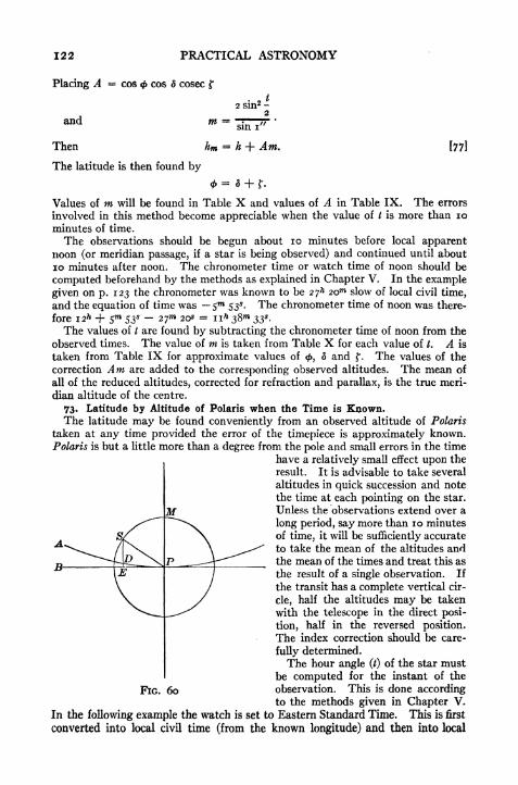
122 PRACTICAL ASTRONOMY
Placing A = cos <j> cos 5 cosec f
and m
Then km
The latitude is then found by
[771
Values of m will be found in Table X and values of A in Table IX. The errors
involved in this method become appreciable when the value of / is more than 10
minutes of time.
The observations should be begun about 10 minutes before local apparentnoon (or meridian passage, if a star is being observed) and continued until about
10 minutes after noon. The chronometer time or watch time of noon should be
computed beforehand by the methods as explained in Chapter V. In the example
given on p. 123 the chronometer was known to be 27^ 2om slow of local civil time,
and the equation of time was $m
53*. The chronometer time of noon was there-
fore 12** H- 5m
53* 27 20* = ii* 38"* 33*.
The values of / are found by subtracting the chronometer time of noon from the
observed times. The value of m is taken from Table X for each value of t. A is
taken from Table IX for approximate values of<f>,
d and |". The values of the
correction Am are added to the corresponding observed altitudes. The mean of
all of the reduced altitudes, corrected for refraction and parallax, is the true meri-
dian altitude of the centre.
73. Latitude by Altitude of Polaris when the Time is Known.The latitude may be found conveniently from an observed altitude of Polaris
taken at any time provided the error of the timepiece is approximately known.Polaris is but a little more than a degree from the pole and small errors in the time
have a relatively small effect upon the
result. It is advisable to take several
altitudes in quick succession and note
the time at each pointing on the star.
Unless the observations extend over a
long period, say more than 10 minutes
of time, it will be sufficiently accurate
to take the mean of the altitudes andthe mean of the times and treat this as
the result of a single observation. If
the transit has a complete vertical cir-
cle, half the altitudes may be taken
with the telescope in the direct posi-
tion, half in the reversed position.
The index correction should be care-
fully determined.
The hour angle (/) of the star mustbe computed for the instant of the
FIG. 60 observation. This is done accordingto the methods given in Chapter V.
In the following example the watch is set to Eastern Standard Time. This is first
converted into local civil time (from the known longitude) and then into local
A

OBSERVATIONS FOR LATITUDE 123
Example.
OBSERVATIONS OP SUN FOR LATITUDEStation, Smyrna Mills, Me.Theodolite of mag'r No. 20.
Chronometer No. 245.
Date, Friday, August 5, 1910Observer, H. E. McComb
Temperature, 24 C.
COMPUTATION OF LATITUDE FROM CIRCUMMERIDIANALTITUDES OF SUN
Station, Smyrna Mills, Me. Date, August 5, 1910.
Chron. correction on L. M. T. H-27m 20*
Local mean time of app. noon 12 05 53Chron. time of apparent noon ii 38 33

124 PRACTICAL ASTRONOMY
sidereal time (see Art. 37). The hour angle, /, is the difference between the sidereal
time and the star's right ascension.
The latitude is computed by the formula
<i>= h - p cos / 4- 2- p* sin2 / tan h sin i" [78]
the polar distance, p, being in seconds. For the derivation of this formula see
Chauvenet, Spherical and Practical Astronomy, Vol. I, p. 253.
In Fig. 60 P is the pole, 5 the star, MS the hour angle, and PDA the parallel
of altitude through the pole. The point D is therefore at the same altitude as
the pole. The term p cos t is approximately the distance from S to E, a point on
the 6-hour circle PB. The distance desired is SD, the diffeernce between the alti-
tude of S and the altitude of the pole. The last term of the formula represents
very nearly this distance DR. When 5 is above the pole DE diminishes SE;when S is below the pole it increases it.
Example i.
Observed altitudes of Polaris, Jan. 9, 1907
Watch Altitudes
649" 26* 43 28' 30"5 1 45 28 3054 14 28 oo
56 45 28 oo
Mean 6h 53 02^.5 Mean 43 28' 15"
Index correction, i' oo"; p = i n' 09" = 4269"; t is found from the observed
watch times to be 13 50'. 7.*
log p = 3-63033 log const. = 4-3845
log cos t = 9.98719 log p2 = 7.2607
i / L j\ ~~~s loe sin2/
ft?,008 '}
:0.3798
last term = H-2".4
Observed alt. = 43 28' 15"Index corr. = i ooRefraction = i oo
43 26' 15"ist and 2nd terms i 09 03
Latitude 42 if 12" N.
This computation may be greatly shortened by the use of Table I of the Epheme-ris, or Table I of the Nautical Almanac. In the Ephemeris the total correction to
the altitude is tabulated for every 3 of hour angle and for every 10" of declination.
In the Almanac the correction is given for every iom of local sidereal time.
Example 2.
The observed altitude of Polaris on March 10, 1925 = 42 20'; Watch time =8* 49 30* P.M.; watch 30* slow of E. S. T. Long. 71 10' W. Index correction,-fi
r. Declination of Polaris, +88 54' 18"; right ascension, i* 33 35*.6
* If the error of the watch is known the sidereal time may be found by themethods explained in Chap, V. For methods of finding the sidereal time by direct
observation see Chap. XI.

OBSERVATIONS FOR LATITUDES 125
Watch 8* 49 30* Observed alt. 42 20'
Error 30 I. C. +iE. S. T. 8* 50"* oo P.M. Refr. -i .0
Civ. Time = 20 50 oo h 42 20'.oDif. Long. 15 20 Corr., Table I +13 .0
Loc. Civ. Time = 21*05 2oS Latitude 42 33^.0Table III = 3 27 .9
Sun's R. A. -f- 1 2ft = ii 08 36.1 Note: From the Almanac the correc-Table III (Long.) 46_.8 tion for Loc. Sid. Time 8^ i8 io.8
32^ iSm 10s .8 is H-IS'.O. From the Ephemeris
24the correction for hour angle 6*
Loc. Sid. Time = "8* 18" io*.8 "? ;.?and
Declination+88
Rt.Asc.Star = 133 35.6 & l8 * +13' ". The latter
T , f .^ 2 is more accurate.
Hour Angle of Polaris 6h 44 35^.2
Example 3. Observed altitude of Polaris May 5, 1925 = 41 10' at Gr. Civ.Time 23^ 50"*. Longitude 5^ West.
Gr. Civ. Time 23^ 50 oo*.
Table III 3 54.91R. A. -J-i2* 14 49 23 .08
38^43^17^.9924
Greenwich Sidereal Time 14^43^* I 7s-99
_5Loc. Sid. Time 9^43 i7*.99R. A. Polaris i 33 30 .68
Hour Angle, t, 8h ogm 47^.31
Observed Altitude 41 10' oo"Refraction - i 05
41 08' 55"Correction, Table I (Eph.) +35 58Correction, Table la (Eph.) 5
Latitude 4i44 /
48"N.
74. Precise Latitudes Harrebow-Talcott Method.The most precise method of determining latitude is that known as the " Har-
rebow-Talcott"Method, in which the zenith telescope is employed. Two stars
are selected, one of which will culminate north of the observer's zenith, the other
pouth, and whose zenith distances differ by only a few minutes of angle. Forconvenience the right ascensions should differ by only a few minutes of time,
say 5 to iom . The approximate latitude must be known in advance, that is,
within i' or 2', in order that the stars may be selected. This may be determined
with the zenith telescope, using the method of Art. 71. It will usually be neces-
sary to consult the star catalogues in order to find a sufficient number of pairswhich fulfill the necessary conditions as to difference of zenith distance and differ-
ence of right ascension.
If the first star is to culminate south of the zenith the telescope is turned until
the stop indicates that it is in the plane of the meridian, on the south side, and then
clamped in this position. The mean of the two zenith distances is then set on the
finder circle and the telescope tipped until the bubble of the latitude level is in the
centre of its tube. When the star appears in the field it is bisected with the mi-
crometer wire; at the instant of passing the vertical wire, that is, at culmination,
the bisection is perfected. The scale readings of the ends of the bubble of the lati-
126 PRACTICAL ASTRONOMY
tude level are read immediately, then the micrometer is read and the readir
recorded. The chronometer should also be read at the instant of culminatior
order to verify the setting of the instrument in the meridian.
The telescope is then turned to the north side of the meridian (as indicated bythe stop) and the observations repeated on the other star. Great care should be
taken not to disturb the relation between the telescope and the latitude level.
The tangent screw should not be touched during observation on a pair.
When the observations have been completed the latitude may be computed by the
formula
4>= J(fc + 8n) + %(ms - mn) X R + Hfe + + l(r,
- rn) [79]
in which ms t mn, are the micrometer readings, R the value of i division of the
micrometer, ls , /, the level corrections, positive when the north reading is tl
larger, and r$ , rn, the refraction corrections. Another correction would be require
in case the observation is taken when the star is not exactly on the meridian.
In order to determine the latitude with the precision required IP geodetic opt
ations it is necessary to observe as many pairs as is possible during one night (say
10 to 20 pairs). In some cases observations are made on more than one night in
order to secure the necessary accuracy. By this method the latitude may readily
be determined within o".io (or less) of the true latitude, that is, with an error
of 10 feet or less on the earth's surface.
Questions and Problems
1. Observed maximum altitude of the sun's lower limb, April 27, 1925 = 61 28',
bearing South. Index correction = 4-30". The Eastern Standard Time is
ii* 42 A.M. The sun's declination April 27 at o>* Gr. Civ. T. = +13 35' 51".3;
the varia. per hour is -|-48".i9; April 28, +13 55' oi".o; varia. per hour, 4-47^.62;
the semidiameter is 15' 55^.03 . Compute the latitude.
2. Observed maximum altitude of the sun's lower limb Dec. 5, 1925 = 30 10'.
bearing South. Longitude = 73 W. Equation of time = 4-9 22*. Sun's decli-
nation Dec. 5 at cfi Gr. Civ. T. = 22 16' 54".o; varia. per hour 19^.85;
Dec. 6, 22 24'37".s; varia. per hour, 18".77; semidiameter, 16' is//
.84.
Compute the latitude.
3. The noon altitude of the sun's lower limb, observed at sea Oct. i, 1925 =40 30' 20", bearing South. Height of eye, 30 feet. The longitude is 35 10' W.Equation of time = -f-io 03*.56. Sun's declination Oct. i at oft Gr. Civ. T. =
2 53' 38". 2; varia. per hour = -58". 28; on Oct. 2, 3 16' 56".!; varia. per
hour, 58". 20; semidiameter = i6'oo".57. Compute the latitude.rj
4
4. The observed meridian altitude of 8 Crateris = 33 24', bearing South;index correction, +30"; declination of star = 14 17' 37". Compute the lati-
tude.
5. Observed (ex. meridian) altitude of a Celt at 3^ o8" 49$ local sidereal timSB 51 21'; index correction = i'; the right ascension of a. Ceti = 2^ 57 24^.0
declination = +3 43' 22". Compute the latitude.
6. Observed altitude of Polaris, 41 41' 30"; chronometer time, o* 44 385.5
(local sidereal); chronometer correction =*34*. The right ascension of Polaris
i 25 42*; the declination == -{-88 49' 29". Compute the latitude.
7. Show by a sketch the following three points: i. Polaris at greatest elonga-
tion; 2. Polaris on the 6-hour circle; 3. Polaris at the same altitude as the pole.
(See Art. 73, p. 122, and Fig. 28, p. 37.)
8. Draw a sketch (like Fig. 19) showing why the sun's maximum altitude is
not the same as the meridian altitude.
CHAPTER XI
OBSERVATIONS FOR DETERMINING THE TIME
75. Observation for Local Time.
Observations for determining the local time at any place at
y instant usually consist in finding the error of a timepiece
the kind of time which it is supposed to keep. To find the
Jiar time it is necessary to determine the hour angle of the sun's
entre. To find the sidereal time the hour angle of the vernal
^quinox must be measured. In some cases these quantities
cannot be measured directly, so it is often necessary to measure
other coordinates and to calculate the desired hour angle from
these measurements. The chronometer correction or watch
correction is the amount to be added algebraically to the read-
ing of the timepiece to give the true time at the instant. It is
positive when the chronometer is slow, negative when it is fast.
The rate is the amount the timepiece gains or loses per day;
it is positive when it is losing, negative when it is gaining.
76. Time by Transit of a Star.
The most direct and simple means of determining time is by,
observing transits of stars across the meridian. If the line of
sight of a transit be placed so as to revolve in the plane of the
meridian, and the instant observed when some known star
passes the vertical cross hair, then the local sidereal time at this
instant is the same as the right ascension of the star given in
t^v* Ephemeris for the date. The difference between the ob-
. irved chronometer time T and the right ascension a is the
chronometer correction AT,
>r AT - a - T. [So]
If the chronometer keeps mean solar time it is only necessary
to convert the true sidereal time a into mean solar time by127
128 PRACTICAL ASTRONOMY
Equa. [45], and the difference between the observed and com-
puted times is the chronometer correction.
The transit should be set up and the vertical cross hair sighted
on a meridian mark previously established. If the instrument
is in adjustment the sight line will then swing in the plane of
the meridian. It is important that the horizontal axis should
be accurately levelled; the plate level which is parallel to this
axis should be adjusted and centred carefully, or else a striding
level should be used. Any errors in the adjustment will bejl
eliminated if the instrument is used in both the direct and re-
versed positions, provided the altitudes of the stars observed
in the two positions are equal. It is usually possible to select
stars whose altitudes are so nearly equal that the elimination
of errors will be nearly complete.
In order to find the star which is to be observed, its approxi-
mate altitude should be computed beforehand and set off on
the vertical arc. (See Equa. [i].) In making this computationthe refraction correction may be omitted, since it is not usually
necessary to know the altitude closer than 5 or 10 minutes.
It is also convenient to know beforehand the approximate time
at which the star will culminate, in order to be prepared for the
observation. If the approximate error of the watch is already
known, then the watch time of transit may be computed (Equa.
[45]) and the appearance of the star in the field looked for a
little in advance of this time. If the data from the Ephemeris t
are not at hand the computation may be made, with sufficient*
accuracy for finding the star, by the following method: Com-
pute the sun's R. A. by multiplying 4 by the number of dayssince March 22. Take the star's R. A. from any list of stars
or a star map. The star's R. A. minus the (sun's R. A.
+ 12*) will be the mean local time within perhaps 2m or
3**. This may be reduced to Standard Time by the method
explained in Art. 32. In the surveyor's transit the field of view
is usually about i, so the star will be seen about 2m
before it
reaches the vertical cross hair. Near culmination the star's

OBSERVATIONS FOR DETERMINING THE TIME I2Q
path is so nearly horizontal that it will appear to coincide with
the horizontal cross hair from one side of the field to the other.
When the star passes the vertical cross hair the time should be
noted as accurately as possible. A stop watch will sometimes
be found convenient in field observations with the surveyor's
transit. When a chronometer is used the"eye and ear method "
is the best. (See Art. 61.) If it is desired to determine the
latitude from this same star, the observer has only to set the
horizontal cross hair on the star immediately after making the
time observation, and the reading of the vertical arc will give
the star's apparent altitude at culmination. (See Art. 71.)
The computation of the watch correction consists in finding
the true time at which the star should transit and comparingit with the observed watch time. If a sidereal watch or chro-
nometer is used the error may be found at once since the star's
right ascension is the local sidereal time. If civil time is desired,
the true sidereal time must be converted into local civil time, or
into Standard Time, whichever is desired.
Transit observations for the determination of time can be
much more accurately made in low than in high latitudes.
Near the pole the conditions are very unfavorable.
Example.Observed the transit of a Hydra on April 5, 1925, in longitude
571 2om west. Observed watch time (approx. Eastern Standard
Time) = 8* 48 24* P.M. or 20* 48 24* Civil Time. The right
ascension of a Hydra for this date is gh23 54^.84; the R. A.
of the mean sun +12* is 12* 5 im06*48 at oh Gr. Civ! T. From
Table III the correction for 5* 20 is + 52^.57.
Rt. Asc. of Hydra +24* =33** 23 54^.84
Corrected R. A. sun -f- 1 2* = 12 51 59 .05
Sid. int. since MVt. = 26^ 31 55^.79Table II = -3 21 .82
Local Civil Time = 20^ 28"* 33^.97Red. to 75 merid. = 20 oo .00
Eastern (Civ.) Time = 20* 48 33^.97Watch = 20 48 24
Watch correction = +9^.97 (slow)

130 PRACTICAL ASTRONOMY
77. Observations with Astronomical Transit.
The method previously described for the small transit is the same in principle
as that used with the larger astronomical transits for determining sidereal time-
The chief difference is in the precision with which the observations are made and
the corrections which have to be applied to allow for instrumental errors. The
number of observations on each star is increased by using several vertical threads
or by employing the transit micrometer. These are recorded on the electric chrono-
graph and the times may be scaled off with great accuracy.
When the transit is to be used for time determination it is set on a concrete or
brick pier, levelled approximately, and turned into the plane of the meridian as
nearly as this is known. The collimation is tested by sighting the middle thread
at a fixed point, then reversing the axis, end for end, and noting whether the thread -
is still on the point. The diaphragm should be moved until the object is sighted
in both positions. The threads may be made vertical by moving the telescope
slowly up and down and noting whether a fixed point remains on the middle thread.
The adjustment is made by rotating the diaphragm. To adjust the line of sight
(middle thread) into the meridian plane the axis is first levelled by means of the
striding level, and an observation taken on a star crossing the meridian near the
zenith. This star will cross the middle thread at nearly the correct time even if
the instrument is not closely in the meridian. From this observation the error of
the chronometer may be obtained within perhaps 2 or 3 seconds. The chronometer
time of transit of a circumpolar star is then computed. When this time is indicated
by the chronometer the instrument is turned (by the azimuth adjustment screw)
until the middle thread is on the circumpolar star. To test the adjustment this
process is repeated, the result being a closer value of the chronometer error and a
closer setting of the transit into the plane of the meridian. Before observations
are begun the axis is re-levelled carefully.
The usual list of stars for time observations of great accuracy would include
twelve stars, preferably near the zenith, six to be observed with the"Clamp east,"
six with"Clamp west." This division into two groups is for the purpose of de-
termining the collimation constant, c. In each group of six stars, three should be
north of the zenith and three south. From the discrepancies between the results
of these two groups the constant a may be found for each half set. Sometimes a
is found by including one slow (circumpolar) star in each half set, its observed time
being compared with that of the" time stars," that is those near the zenith. The
inclination of the horizontal axis, b, is found by means of the striding level. The
observed times are scaled from the chronograph sheet for all observations, and the
mean of all threads taken for each star. This mean is then corrected for azimuth
error by adding the quantity
a sin f sec 5.[66]
The error resulting from the inclination of the axis to the horizon is corrected by
addingb cos sec 8 [67]
and finally the collimation error is allowed for by adding
c sec 5. [68]

OBSERVATIONS FOR DETERMINING THE TIME 131
Small corrections for the changing error of the chronometer and for the effect of
diurnal aberration of light are also added. The final corrected time of transit is
subtracted from the right ascension of the star, the result being the chronometer
correction on local sidereal time. The mean of all of the results will usually give
the time within a few hundredths of a second.
78. Selecting Stars for Transit Observations.
Before the observations are begun the observer should pre-
pare a list of stars suitable for transit observations. This
list should include the name or number of the star, its magni-
tude, the approximate time of culmination, and its meridian
altitude or its zenith distance. The right ascensions of consec-
utive stars in the list should differ by sufficient intervals to give
the observer time to make and record an observation and pre-
pare for the next one. The stars used for determining time
should be those which have a rapid diurnal motion, that is,
stars near the equator; slowly moving stars are not suitable
for time determinations. Very faint stars should not be selected
unless the telescope is of high power and good definition; those
smaller than the fifth magnitude are rather difficult to observe
with a small transit, especially as it is difficult to reduce the
amount of light used for illuminating the field of view. The
selection of stars will also be governed somewhat by a consider-
ation of the effect of the different instrumental errors. An in-
spection of Table B, p. 99, will show that for stars near the
zenith the azimuth error is zero, while the inclination error is
a maximum; for stars near the horizon the azimuth error is a
maximum and the inclination error is zero. If the azimuth of
the instrument is uncertain and the inclination can be accurately
determined, then stars having high altitudes should be preferred.
On the other hand, if the level parallel to the axis is not a sensi-
tive one and is in poor adjustment, and if the sight line can be
placed accurately in the meridian, which is usually the case
with a surveyor's transit, then low stars will give the more accu-
rate results. With the surveyor's transit the choice of stars is
somewhat limited, however, because it is not practicable to
>ight the telescope at much greater altitudes than about 70
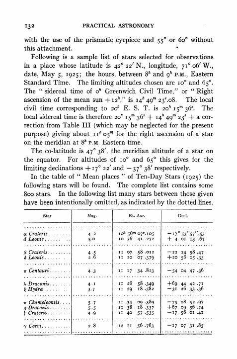
132 PRACTICAL ASTRONOMY
with the use of the prismatic eyepiece and 55 or 60 without
this attachment.
Following is a sample list of stars selected for observations
in a place whose latitude is 42 22' N., longitude, 7io6'W.,date, May 5, 1925; the hours, between 8* and g
hP.M., Eastern
Standard Time. The limiting altitudes chosen are 10 and 65.The "
sidereal time of o* Greenwich Civil Time/7
or"Right
ascension of the mean sun +i2h," is 14* 49 23^.08. The local
civil time corresponding to 2oh E. S. T. is 20^15^36*. The
local sidereal time is therefore 20* 15** 36* + 14^ 49 23* + a cor-
rection from Table III (which may be neglected for the present
purpose) giving about 11^05^ for the right ascension of a star
on the meridian at 8^ P.M. Eastern time.
The co-latitude is 47 38', the meridian altitude of a star on
the equator. For altitudes of 10 and 65 this gives for the
limiting declinations +17 22' and 37 38' respectively.
In the table of" Mean places
"of Ten-Day Stars (1925) the
following stars will be found. The complete list contains some
800 stars. In the following list many stars between those given
have been intentionally omitted, as indicated by the dotted lines.

OBSERVATIONS FOR DETERMINING THE TIME 133
In this list there are three stars, ft Crateris, Hydra, and
f Crateris, whose decimations and right ascensions fall within the
required limits. There are 13 others which could be observed
but were omitted in the above list to save space. After select-
ing the stars to be observed the approximate watch time of
transit of the first star should be computed. The times of the
other stars may be estimated with sufficient accuracy by means
of the differences in the right ascension. The watch times
will differ by almost exactly the difference of right ascension.
The altitudes (or the zenith distances) should be computedto the nearest minute. This partial list would then appear as
follows:
In searching for stars the right ascension should be examined
first. As the stars are arranged in the list in the order of in-
creasing right ascension it is only necessary to find the right
ascension for the time of beginning the observations and then
follow down the list. Next check off those stars whose decli-
nations fall within the limits that have been fixed. Finally
, note the magnitudes and see if any are so small as to make the
star an undesirable one to observe.
When the stars have been selected, look in the table of"Ap-
parent Places of stars"
to obtain the right ascension and decli-
nation for the date. These may be obtained by simple inter-
polation between the values given for every 10 days. The
mean places given in the preceding table may be in error for any
particular date by several seconds. With the correct right
ascensions the exact time of transit may be calculated as pre-
viously explained.
134 PRACTICAL ASTRONOMY
79. Time by Transit of Sun,
The apparent solar time may be determined directly by ob-
serving the watch times when the west and the east limbs of the
sun cross the meridian. The mean of the two readings is the
watch time of the instant of Local Apparent Noon, or 12* ap-
parent time. This i2h
is to be converted into Local Civil Time
and then into Standard Time. If only one edge of the sun's
disc can be observed the time of transit of the centre may be
found by adding or subtracting the"time of semidiameter
passing the meridian." This is given in the Ephemeris for
Washington Apparent Noon. The tabulated values are in
sidereal time, but may be reduced to mean time by subtracting
o*.i8 or o*.i9 as indicated in a footnote.
Example.The time of transit of the sun over the meridian 71 06' W. is to be observed
March 2, 1925.
Local Apparent Time =12'* oom oo8 G. C. T. = 16^.95
Equation of Time = 12 19 .93
Local Civil Time = 12'* 12 igs
.93 Equa. of Time at o^ = i2m i6*.29
Longitude diff.> 15 36 . 0^.517 X 7^.05=
3 .64
Eastern Standard Time = nh 56 43^93 Corrected Equa. of T. = i2m 10^.93
The observed time of the west and east limbs are n^ 55 47* and nh57 56* re-
spectively. The mean of these is n^ 56^ 51^.5; the watch is therefore 7*.6 fast.
The time of the semidiameter passing the meridian is iw o5*.i6. If the second
observation had been lost the watch time of transit of the centre would be n* 55"*
47* H- io5*.i6 = nh 56 5 2s . 1 6, and the resulting watch correction would be
-8.2.
80. Time by an Altitude of the Sun.
The apparent solar time may be determined by measuringthe altitude of the sun when it is not near the meridian, and then
solving the PZS triangle for the angle at the pole, which is
the hour angle of the sun east or west of the meridian. Thewest hour angle of the sun is the local apparent time. Theobservation is made by measuring several altitudes in quicksuccession and noting the corresponding instants of time. Themean of the observed altitudes is assumed to correspond to the
mean of the observed times, that is, the curvature of the path

OBSERVATIONS FOR DETERMINING THE TIME 135
of the sun is neglected. The error caused by neglecting the
correction for curvature is very small provided the sun is not
near the meridian and the series of observations extends over
but a few minutes' time, say iom . The measurement of alti-
tude must of course be made to the upper or the lower limb
and a correction applied for the semidiameter. The observa-
tions may be made in two sets, half the altitudes being taken
on the upper limb and half on the lower limb, in which case no
'semidiameter correction is required. The telescope should be
reversed between the two sets if the instrument has a complete
vertical circle. The mean of the altitudes must be corrected
for index error, refraction, and parallax, and for semidiameter
if but one limb is observed. The declination at oh Gr. Civ.
Time is to be corrected by adding the"variation per hour "
multiplied by the number of hours in the Greenwich civil time.
If the watch used is keeping Standard time the Greenwich time
is found at once (see Art. 32). If the watch is not more than
2mor 3
min error the resulting error in the declination will not
exceed 2" or 3", which is usually negligible in observations with
small instruments. If the Standard time is not known but the
longitude is known then the Greenwich time could be com-
puted if the local time were known. Since the local time is the
quantity sought the only way of obtaining it is first to compute
the hour angle (/) using an approximate value of the declination.
From this result an approximate value of the Greenwich civil
time may be computed. The declination may now be computed
more accurately. A re-computation of the hour angle (/),
using this new value of the declination, may be considered
final unless the declination used the first time was very much in
serror.
In order to compute the hour angle the latitude of the place
must be known. This may be obtained from a reliable map or
may be observed by the methods of Chapter X. The precision
with which the latitude must be known depends upon how pre-
cisely the altitudes are to be read and also upon the time at

136 PRACTICAL ASTRONOMY
which the observation is made. When the sun is near the primevertical the effect of an error in the latitude is small.
The value of the hour angle is computed by applying any of
the formulae for / in Art. 19. This hour angle is converted into
hours, minutes and seconds; if the sun is west of the meridian
this is the local apparent time P.M., but if the sun is east of the
meridian this time interval is to be subtracted from i2hto obtain
the local apparent time. This apparent time is then converted
into mean (civil) time by subtracting the (corrected) equation
of time. The local time is then converted into Standard time
by means of the longitude difference. The difference between
the computed time and the time read on the watch is the watch
correction. This observation is often combined with the ob-
servation on the sun for azimuth, the watch readings and alti-
tude readings being common to both.
Example.
Nov. 28, 1925.
Lower limb
(Tel. dir.)
Upper limb
(Tel. rev;)
MeanRefraction and parallax
is
15 5516 08
15 26'.o
3 -3
iS22/
. 7
Lat. 42 22'; Long. 71 06'.
Watch (E. S. T.)
Sh 39W 42* A.M.
8 42 19
8 45 348 47 34
8" 43 47*. 2 E. S. T. (Approx.)5
4>= 42 22'
h - 15 22 .7
p = III 17 .2
25= 169 Ol'.9
s 84 30^.9 log cos 8.98039s h = 69 08 .2 log sin 9.97055^ <
SB 42 08 .9 log csc 0.17324s _ p = _. 26 46 .3 log sec 0.04924
2)0.17342
13* 43m 47s - 2 Gr. Civ. T. (Approx.)
Decl. at <# = - 21 10' 58".8
-27".i4 X i3*-7= -6 ii .8
5= -2ii7 /io".6
p = in, 17 10 .6
Eq. of t. at
o*.828 X i3*
Eq. of t.
14*.56ii .34
-fi2o3*.22
log tan - '
9 58671
o ^A>= 21 06' 43
42 13' 26"
: 2 48* 53^.7

OBSERVATIONS FOR DETERMINING THE TIME 137
L. A. T. = 9*11 06X3Eq. of t. = +12 03 .2
Loc. Civ. T. = 8* 59 03*. i
Long, cliff. == 15 36 .
Eastern Standard Time = 8h 43"* 275.1
Watch = 8 43 47 .2
Watch fast 20*. i
The most favorable conditions for an accurate determination
of time by this method are when the sun is on the prime vertical
land the observer is on the equator. When the sun is east or
west it is rising or falling at its most rapid rate and an error in the
altitude produces less error in the calculated houf angle than the
same error would produce if the sun were near the meridian. The
nearer the observer is to the equator the greater is the inclina-
tion of the sun's path to the horizon, and consequently the
greater its rise or fall per second of time. If the observer were
at the equator and the declination zero the sun would rise or
fall i'in 4
sof time. In the preceding example the rise is i' in
about &sof time. 'When the observer is near the pole the method
is practically useless.
Observations on the sun when it is very close to the horizon
should be avoided, however, even when the sun is near the prime
vertical, because the errors in the tabulated refraction correc-
tion due to variations in temperature and pressure of the air
are likely to be large. Observations should not be made when
the altitude is less than 10 if it can be avoided.
81. Time by the Altitude of a Star.
The method of the preceding article may be applied equally
well to an observation on a star. In this case the parallax and
semidiameter corrections are zero. If the star is west of the me-
ridian the computed hour angle is the star's true hour angle;
if the star is east of the meridian the computed hour angle mustbe subtracted from 24*. The sidereal time is then found by
adding the right ascension of the star to its hour angle. If
mean time is desired the sidereal time thus found is to be con-
verted into mean solar time by Art. 37. Since it is easy to select

138 PRACTICAL ASTRONOMY
stars in almost any position it is desirable to eliminate errors in
the measured altitudes by taking two observations, one on a
star which is nearly due east, the other on one about due west.
The mean of these two results will be nearly free from instru-
mental errors, and also from errors in the assumed value of the
observer's latitude. If a planet is used it will be necessary to
know the Gr. Civ. Time with sufficient accuracy for correcting
the right ascension and declination.
Example.Observed altitude of a Bo'otis (Arcturus) on Apr. 15, 1925 = 40 10' (east).
Watch, 8* 54 20* P.M. Latitude = 42 18' N., Long. =71 18' W. Rt. Asc. a
Bodtis, 14* i2m 15^.6; decl. -f *934' 14"- Rt. Asc. Mean Sun +12* = i3^3O>
32*.OI.
Obs. alt. 40 10'
Refr. -i .1
h 40 o8'.9
= 42 iS'.o log sec 0.13098h = 40 08 .9
p = 70 25 .8 log esc 0.02584
2)152 52 .7
s = 76 26'.3 log cos 9-37OI3s h ~ 36 17 .4 log sin 9.77223
log sin - = 9.64959
-'= 26 30' 15"
/ = 53 oo' 30" (east)
=3/ 32^02* (east)
Rt. Asc. of star = 14* 12^* 153.6
Loc. Sid. T. = io^4oi3*.6Long. W. = 4 45 12 .
Gr. Sid. T.*
15* 25"* 25^.6R. A. Sun 4-i2 ft = 13 30 32 .o
i* 54m 53*-6Table II 18 .8
Gr. Civil T. = i* 54^ 34^.8
J_Eastern. Stand. Time 20* 54"* 34*.8
= 8 54 34.8P.M.Watch 8 54 20 P.M.
Watch i4*.8 slow
OBSERVATIONS FOR DETERMINING THE TIME 139
82. Effect of Errors in Altitude and Latitude.
In order to determine the exact effect upon i of any error in
the altitude h let us differentiate equation [8] with respect
to h, the quantities <t> and 5 being regarded as constant.
sin h sin<t>
sin d + cos < cos 8 cos t. [8]
Differentiating,dt
cos h = o cos 6 cos 5 sm /
ahdt cos h
dh cos < cos 6 sin
= V-^ by Equa. [12]. [81]cos sin Z J M
An inspection of this equation shows that when Z = 90 or 270
sin Z is a maximum and a minimum for any given value of <.(trl
It also shows that the smaller the latitude, the greater is its
cosine and consequently the smaller the value of . The mostan
favorable position of the body is therefore on the prime vertical.
The negative sign shows that the hour angle decreases as the
altitude increases. When Z is zero (body on meridian) the value
of is infinite and t cannot be found from the observed altitude.dh
The effect of an error in the latitude may be found by differ-
entiating [8] with respect to <. The result is
o = cos </> sin d + cos 6 ( cos sin t~ cos / sin <)a</>
. dtcos <t> cos d sin / cos sm 6 sm
<l> cos d cos /
a<t>
= cos/? cosZ by [n]
.dt^ _ cos h cos Zd(l> cos <t>
cos d sin t
cosZ_ . by I I2 |
sin Z cos ^J l J

140 PRACTICAL ASTRONOMY
= !___. i82 i
cos <t> tan Z '
This shows that when Z = 90 or 270 an error in < has no effect
on /, since = o. In other words, the most favorable position
of the object is on the prime vertical. It also shows that the
method is most accurate when the observer is on the equator.
83. Time by Transit of Star over Vertical Circle through Polaris.*
In making observations by this method the line of sight of the telescope is set
in the vertical plane through Polaris at any (observed) instant of time, and the
time of transit of some southern star across this plane is observed immediately
afterward; the correction for reducing the star's right ascension to the true sidereal
time of the observation is then computed and added to the right ascension. The
advantages of the method are that the direction of the meridian does not have to
be established before time observations can be begun, and that the interval which
must elapse between the two observed times is so small that errors due to the
instability of the instrument are reduced to a minimum.
The method of making the observation is as follows : Set up the instrument and
level carefully; sight the vertical cross hair on Polaris (and clamp) and note and
record the watch reading; then revolve the telescope about the horizontal axis,
being careful not to disturb its azimuth; set off on the vertical arc the altitude of
some southern star (called the time-star) which will transit about 4m or $m
later;
note the instant when this star passes the vertical cross hair. It will be of as-
sistance in making the calculations if the altitude of each star is measured im-
mediately after the time has been observed. The altitude of the time-star at
the instant of observation will be so nearly equal to its meridian altitude that
no special computation is necessary beyond what is required for ordinary transit
observations. If the times of meridian transit are calculated beforehand the
actual times of transit may be estimated with sufficient accuracy by noting the
position of Polaris with respect to the meridian. If Polaris is near its elongation
then the azimuth of the sight line will be a maximum. In latitude 40 the-^
azimuth of Polaris for 1925 is about i 26'; a star on the equator would then
pass the vertical cross hair nearly 4 later than the computed time if Polaris is
at eastern elongation (see Table B, p. 99). If Polaris is near western elongation
the star will transit earlier by this amount. In order to eliminate errors in the
adjustment of the instrument, observations should be made in the erect and in-
verted positions of the telescope and the two results combined. A new setting
should be made on Polaris just before each observation on a time-star.
* For a complete discussion of this method see a paper by Professor George
O. James, in the Jour. Assoc. Eng. Soc., Vol. XXXVII, No. 2; also Popular As-
tronomy, No. 1 7 2. A method applicable to larger instruments is given by Professor
Frederick H." Seats, in Bulletin No. 5, Laws Observatory, University of Missouri.
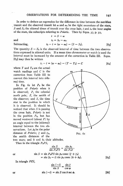
OBSERVATIONS FOR DETERMINING THE TIME 141
In order to deduce an expression for the difference in time between the meridian
transit and the observed transit let a and <x be the right ascensions of the stars,
S and So the sidereal times of transit over the cross hair, i and to the hour anglesof the stars, the subscripts referring to Polaris. Then by Equa. 37, p. 52,
t = S - a.
and to= So <XQ.
Subtracting, h - / = (~
o)-
(S-
So). [83]
The quantity 5 So is the observed interval of time between the two observa-
tions expressed in sidereal units. If a mean time chronometer or watch is used the
interval must be increased by the amount of the correction in Table III. Equa.
[83] may then be written
j-
t = (a-
)- (T - To)
- C [84]
where T and To are the actual
watch readings and C is the
correction from Table III to
convert this interval into side-
real time.
In Fig. 61 let PQ be the
position of Polaris when it
is observed; P, the celestial
north pole; Z, the zenith of
the observer; and S, the time
star in the position in which
it is observed. It should be
noticed that when S is passing
the cross hair, Polaris is not
in the position Po, but has
moved westward (about P) byan angle equal to the (sidereal)
interval between the two ob-
servations. Let PQ be the polar
distance of Polaris ;and
,v
the zenith distances of the
two stars; and h and ho their altitudes.
Then in the triangle PoPS,sin S _ sin po
sinS
In triangle PZSy
or
sin P PS sin PoS
sin P PS sin po cosec ( + f )
= sin (to t) sin po cosec (h -f- ho).
sin (/) _ sin f
sin S~~
cos <f>
sin ( /)= sin S cos h sec <.
[85]
[86]
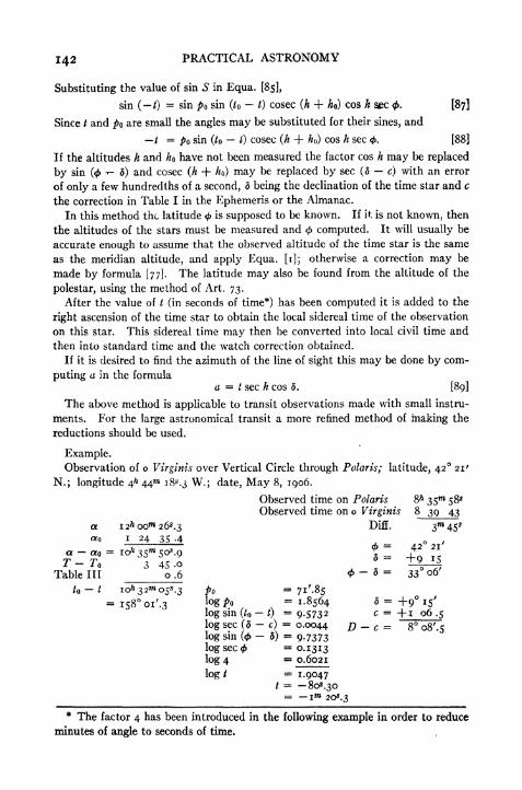
142 PRACTICAL ASTRONOMY
Substituting the value of sin S in Equa. [85],
sin ( /)= sin po sin (/ t) cosec (h + ho) cos h sec <. [87]
Since / and po are small the angles may be substituted for their sines, and
/ = po sin (to t) cosec (h -f ho) cos h sec <. [88]
If the altitudes h and ho have not been measured the factor cos h may be replaced
by sin (<-r- 6) and cosec (/5 + //o) may be replaced by sec (5 c) with an error
of only a few hundredths of a second, 5 being the declination of the time star and c
the correction in Table I in the Ephemeris or the Almanac.
In this method the latitude <f>is supposed to be known. If it is not known, then
the altitudes of the stars must be measured and $ computed. It will usually be
accurate enough to assume that the observed altitude of the time star is the same
as the meridian altitude, and apply Equa. [i]; otherwise a correction may be
made by formula [77]. The latitude may also be found from the altitude of the
polestar, using the method of Art. 73.
After the value of / (in seconds of time*) has been computed it is added to the
right ascension of the time star to obtain the local sidereal time of the observation
on this star. This sidereal time may then be converted into local civil time and
then into standard time and the watch correction obtained.
If it is desired to find the azimuth of the line of sight this may be done by com-
puting a in the formulaa t sec h cos 6. [89]
The above method is applicable to transit observations made with small instru-
ments. For the large astronomical transit a more refined method of making the
reductions should be used.
Example.Observation of o Virginia over Vertical Circle through Polaris; latitude, 42 21'
N.; longitude 4^ 44 18^.3 W.; date, May 8, 1906.
Observed time on Polaris &h 35 58*Observed time on o Virginis 8 39 43
a I2i*oom 26s .3 Diff. 3m
45*o I 24 35 .4 _ o /
Table III 0.6 <t>~ * = 33 06'
05^.3 p = yi.gs= i58oi'.3
logo =1.8564 5 = +9 15'
log sin (to t)= 9.5732 c = +i 06.5
log sec (5-
c)= 0.0044 D - c = 8 oS'.s
log sin (0 5)= 9.7373
log sec <= 0.1313
log 4 SB 0.6021
log / = 1.9047/ = -808.30= 1 20^.3
* The factor 4 has been introduced in the following example in order to reduce
minutes of angle to seconds of time.
OBSERVATIONS FOR DETERMINING THE TIME 143
The true sidereal time may now be found by subtracting im 2o*.3 from the right
ascension of o Virginis, the result being as follows:
a = 12" oo^ 26^.3
/ = I 20 .3
S as Hft 59n 06X0
The local civil time corresponding to this instant of sidereal time for the date is
20& 55* i4*.5. tThe corresponding Eastern Standard time is 20* 39 32^.8, or 8* 39OT
32^.8 P.M. The difference between this and the watch time, 8* 39 43*, shows that
the watch was lo*^ fast.
84. Time by Equal Altitudes of a Star.
If the altitude of a star is observed when it is east of the meridian at a certain
altitude, and the same altitude of the same star again observed when the star is
west of the meridian, then the mean of the two observed times is the watch reading
for the instant of transit of the star. It is not necessary to know the actual value
of the altitude employed, but it is essential that the two altitudes should be equal.
The disadvantage of the method is that the interval between the two observations
is inconveniently long.
85. Time by Two Stars at Equal Altitudes.
In this method the sidereal time is determined by observing when two stars
have equal altitudes, one star being east of the meridian and the other west. If
the two stars have the same- declination then the mean of the two right ascensions
is the sidereal time at the instant the two stars have the same altitude. As it is
not practicable to find pairs of stars having exactly the same declination it is neces-
sary to choose pairs whose declinations differ as little as possible and to introduce
a correction for the effect of this difference upon the sidereal time. It is not
possible to observe both stars directly with a transit at the instant when their
altitudes are equal; it is necessary, therefore, to observe first one star at a certain
altitude and to note the time, and then to observe the other star at the same alti-
tude and again note the time. The advantage of this method is that the actual
value of the altitude is not used in the computations; any errors in the altitude
due either to lack of adjustment of the transit or to abnormal refraction are there-
fore eliminated from the result, provided the two altitudes are made equal. In
preparing to make the observations it is well to compute beforehand the approxi-
mate time of equal altitudes and to observe the first star two or three minutes
before the computed time. In this way the interval between the observations
may be kept conveniently small. It is immaterial whether the east star is observed
first or the west star first, provided the proper change is made in the computation.If one star is faint it is well to observe the bright one first; the faint star may then
be more easily found by knowing the time at which it should pass the horizontal
cross hair. The interval by which the second observation follows the time of
equal altitudes is nearly the same as the interval between the first observation
and the time of equal altitudes. It is evident that in the application of this methodthe observer must be able to identify the stars he is to observe. A star map is
of great assistance in making these observations.
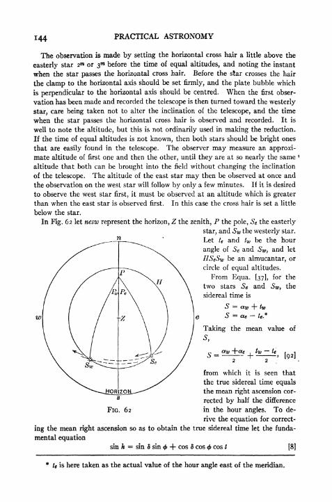
144 PRACTICAL ASTRONOMY
The observation is made by setting the horizontal cross hair a little above the
easterly star 2"* or 3 before the time of equal altitudes, and noting the instant
when the star passes the horizontal cross hair. Before the star crosses the hair
the clamp to the horizontal axis should be set firmly, and the plate bubble which
is perpendicular to the horizontal axis should be centred. When the first obser-
vation has been made and recorded the telescope is then turned toward the westerly
star, care being taken not to alter the inclination of the telescope, and the time
when the star passes the horizontal cross hair is observed and recorded. It is
well to note the altitude, but this is not ordinarily used in making the reduction.
If the time of equal altitudes is not known, then both stars should be bright ones
that are easily found in the telescope. The observer may measure an approxi-
mate altitude of first one and then the other, until they are at so nearly the same <
altitude that both can be brought into the field without changing the inclination
of the telescope. The altitude of the east star may then be observed at once and
the observation on the west star will follow by only a few minutes. If it is desired
to observe the west star first, it must be observed at an altitude which is greater
than when the east star is observed first. In this case the cross hair is set a little
below the star.
In Fig. 62 let nesw represent the horizon, Z the zenith, P the pole, Se the easterly
star, and Sw the westerly star.
Let te and tw be the hour
angle of Se and Sw, and let
HSeSw be an almucantar, or
circle of equal altitudes.
From Equa. [37], for the
two stars Se and Sw ,the
sidereal time is
te*
Taking the mean value of
s,
, Mfrom which it is seen that
the true sidereal time equals
the mean right ascension cor-
rected by half the difference
FIG. 62 in the hour angles. To de-
rive the equation for correct-
ing the mean right ascension so as to obtain the true sidereal time let the funda-
mental equation
sin h = sin 5 sin <j> -f- cos 5 cos <f> cos / [8]
te is here taken as the actual value of the hour angle east of the meridian.

OBSERVATIONS FOR DETERMINING THE TIME
be differentiated regarding d and t as the only variables, then there results
o sin < cos 8 cos 5 cos<f> sin t j- cos 4> cos t sin 6,
from which may be obtained
dt== tan<fr __
tang
dS~
sin*
If the difference in the decimation is small, dd may be replaced by J (dwin which case <ft will be the resulting change in the hour angle, or i (tw fc).
The equation for the sidereal time then becomes
c _~~ 4- _ tan 61
tan / J [92]Lsin/
in which (8W 8e} must be expressed in seconds of time. 5 may be taken as the
mean of 8e and fa- The value of t would be the mean of te and tw if the two stars
were observed at the same instant, but since there is an appreciable interval be-
tween the two times / must be found by
, ,
[93]
and Te being the actual watch readings.
LIST FOR OBSERVING BY EQUAL ALTITUDES
Lat., 42 21' N. Long., 4^ 44"* 18* W. Date, Apr. 30, 1912.

146 PRACTICAL ASTRONOMY
If the west star is observed first, then the last term becomes a negative quantity.
Strictly speaking this last term should be converted into sidereal units, but the
effect upon the result is usually very small. In regard to the sign of the correction
to the mean right ascension it should be observed that if the west star has the
greater declination the time of equal altitudes is later than that indicated by the
mean right ascension. In selecting stars for the observation the members of a
pair should differ in right ascension by 6 to 8 hours, or more, according to the
declinations. Stars above the equator should have a longer interval between
them than those below the equator. On account of the approximations made in
deriving the formula the decimations should differ as little as possible. If the
declinations do not differ by more than about 5, however, the result will usually
be close enough for observations made with the engineer's transit. From the
extensive star list now given in the American Ephemeris it is not difficult to select
a sufficient number of pairs at any time for making an accurate determination
of the local time. On page 141 is a short list taken from the American Ephemerisand arranged for making an observation on April 30, 1912.
Following is an example of an observation for time by the method of equal alti-
tudes.
Example.
Lat, 42 21' N. Long,, 4* 44 i8 W. Date, Dec. 14, 1905.
57 36' 3i"-5
Decl.
+3 43' 69".!+ 2 55 44 .o
+3 19' 56".62) o 48 25 .1
=24' i2".6
= -"96X84
Te
Watch.
i8m oo*
22 13
^ 20"* 06X504 13
Mean R. A. = 23^ 09*" 02*.8
Corn = 01 41 .o
Sid. Time =23^ 07"* 2i*.8
The local civil time corre-
sponding to this is
17 35m 43sA
Long. diff. 15 42 .o
Eastern time 17* 20 01*4=
5 20 01 .4 P.M.
Watch reading 5 20 06 .5 Corr.
Watch fast 5*.i
IQI'.O = i
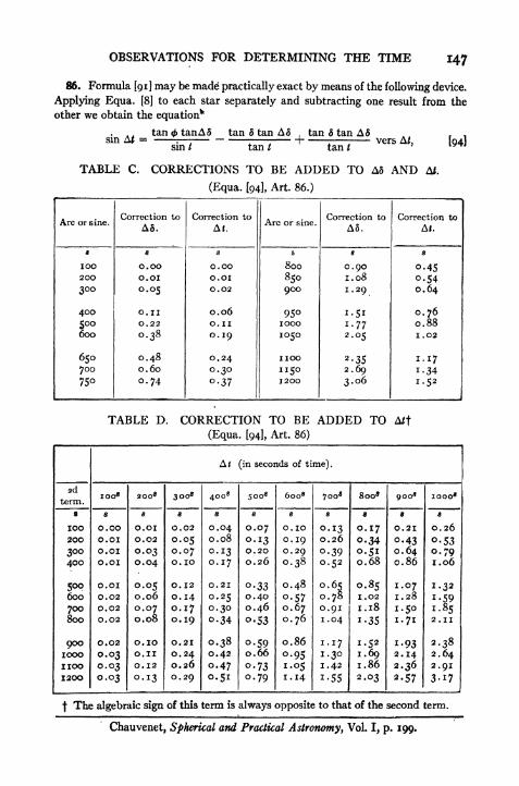
OBSERVATIONS FOR DETERMINING THE TIME 147
86. Formula [91] may be made practically exact by means of the following device.
Applying Equa. [8] to each star separately and subtracting one result from the
other we obtain the equation*
tan (ft tanAS tan 5 tan A5 tan d tan A6sin AJ ;
sin/ tan/ tan/
.
,
vers A/}
TABLE C. CORRECTIONS TO BE ADDED TO A3 AND A/.
(Equa. [94], Art. 86.)
TABLE D. CORRECTION TO BE ADDED TO A/t
(Equa. [94], Art. 86)
f The algebraic sign of this term is always opposite to that of the second term.
Chauvenet, Spherical and Practical Astronomy, Vol. I, p. 199.

148 PRACTICAL ASTRONOMY
where A5 is half the difference in the declinations and AJ is the correction to the
mean right ascension. If sin A/ and tan A 5 are replaced by their arcs and the
third term dropped, this reduces to Equa. [91], except that A3 and At are finite
differences instead of infinitesimals. In order to compensate for the errors thus
produced let A 6 be increased by a quantity equal to the difference between the
arc and the tangent (Table C) ;and let a correction be added to the sum of the first
two terms to allow for the difference between the arc and sine of A/ (Table C).
With the approximate value of A/ thus obtained the third term of the series may be
taken from Table D. By this means the precision of the computed result may be
increased, and the limits of A 5 may therefore be extended without increasing the
errors arising from the approximations.
Example.
Compute the time of equal altitudes of a Bootis and i Geminorum on Jan. i,
1912, in latitude 42 21'. R. A. a Bootis = 14'* nm 37^98; decl. = +19 38' i5".2.
R. A. i Geminorum =7" 20 i6.8s; decl. = +27 58' 3o".8.
14* n 37^.98
7 20 16 .85
2) 6* 51"* 213.13
3/ 25"* 403.56t = 51 25' o8".4
log AS = 3.000993
log tan <j>- 9.959769
log esc/ 0.106945
3.067707
ist term = n68*.7i2d term = 352 .76
A/ (approx.)
Corr., Table C = +Corr., Table D =
A/ = +8i7*.o6
27 58' 3o".819 38 15 .2
2) 8 20' i5".6
A5 = 4 10' 07".8=
1000^.52
Corr., Table C i .77
A5 = ioo2*.29
log A5 = 3.00099log tan 5 = 9.64462log cot/ = 9.90187
2.54748
2d term = 352.76
Mean R. A. = 10 45 57 .42
Sid. Time of Equal Alt. = 10* 59"* 34*48
For refined observations the inclination of the vertical axis should be measured
with a spirit level and a correction applied to the observed time. With the engi-
neer's transit the only practicable way of doing this is by means of the plate-level
which is parallel to the plane of motion of the telescope. If both ends of this
level are read at each observation, denoting the reading of the object end and Ethe eye end of the bubble, then the change in the inclination is expressed by
i = - E) - (V -'))
X ~>

OBSERVATIONS FOR DETERMINING THE TIME 149
where d is the angular value of one scale division in seconds of arc. The correction
to the mean watch reading is
Corr.30 sin S cos 5 30 cos < sin Z
in which S may be taken from the Azimuth* tables or Z may be found from the
measured horizontal angle between the stars. If the west star is observed at a
higher altitude than the east star (bubble nearer objective), the correction must
be added%to the mean watch reading. If it is applied to the mean of the right
ascensions the algebraic sign must be reversed.
87. The correction to the mean right ascension of the two stars may be con-
veniently found by the following method, provided the calculation of the paral-
lactic angle, S in the PZS triangle, can be avoided by the use of tables. Publica-
tion No. 120 of the U. S. Hydrographic Office gives values of the azimuth angle
for every whole degree of latitude and declination and for every iom of hour angle.
The parallactic angle may be obtained from these tables (by interpolation) by
interchanging the latitude and the declination, that is, by looking up the decli-
nation at the head of the page and the latitude in the line marked "Declination/'
For latitudes under 23 it will be necessary to use Publication No. 71
In taking out the angle the table should be entered with the next less whole
degree of latitude and of declination and the next less iom of hour angle, and the
corresponding tabular angle written down; the proportional parts for minutes
of latitude, of declination, and of hour angle are then taken out and added alge-
braically to the first angle. The result may be made more accurate by workingfrom the nearest tabular numbers instead of the next less. The instructions given
in Pub. 1 20 for taking out the angle when the latitude and declination are of
opposite sign should be modified as follows. Enter the table with the supplement
of the hour angle, the latitude and declination being interchanged as before, and
the tabular angle is the value of S sought.
Suppose that two stars have equal declinations and that at a certain instant
thek altitudes are equal, A being east of the meridian and B west of the meridian.
If the declination of B is increased so that the star occupies the position C, then
the star must increase its hour angle by a certain amount x in order to be again
on the almucantar through B. Half of the angle x is the desired correction. In
Fig. 63 BC is the increase in declination; BD is the almucantar through A, Band D-
tand CD is the arc of the parallel of declination through which the star
must move in order to reach BD. The arcs BD and CD are not arcs of great
circles, and the triangle BCD is not strictly a spherical triangle, but it may be
shown that the error is usually negligible in observations made with the engi-
neer's transit if BCD is computed as a spherical triangle or even as a plane triangle.
The angle ZBP is the angle 5 and DBC is 90 - 5. The length of the arc CDis then BC cot S, or (fa - $<?) cot 5. The angle at f is the same as the arc CD'and equals CD sec 5. If (dw 8e) is expressed in minutes of arc and the cor-
*See Arts, 87 and 122 for the method of using these tables.

ISO PRACTICAL ASTRONOMY
rection is to be in seconds of time, then, remembering that the correction is half
the angle xy
Correction = 2 (dw de) cotS sec 5.%
[95]
5 should be taken as the mean of the two declinations, and the hour angle, used
in finding 5, is half the difference in right ascension corrected for half the watch
interval.
The trigonometric formula for determining the correction for equal altitudes is
tan = sin cot i (Si + Sz) sec i (to + to). [96]2 2
By substituting arcs for the sine and tangent this reduces to the equation given
above, except that the mean of Si and 52 is not exactly the same as the value of Sobtained by using the mean of the hour angles.
Z
FIG. 63
The example on p. 146 worked by this method is as follows. From the azimuth
tables, using a declination of 42, latitude 3, and hour angle 3h50"*, the approxi-
mate value of S is 44 05'. Then from the tabular differences,
Correction for 21' decl. = 22'
Correction for 20' lat. = +07Correction for 26* h. a. = +02
The corrected value of S is therefore 43 52'.
2(5W 8e)= 96'.84log
-1.9861 (n)
log cot S 0.0172
log sec 5 0.0007
log corr. 2.0040 (n)
log corr. = 1008.9
This solution is sufficiently accurate for observations made with the engineer's
transit, provided the difference in the declinations of the two stars is not greater
than about 5 and the other conditions are favorable. For larger instruments
and for refined work this formula is not sufficiently exact.
The equal-altitude method, like all of the preceding methods, gives more precise
results in low than in high latitudes.

OBSERVATIONS FOR DETERMINING THE TIME 151
88. Rating a Watch by Transit of a Star over a Range.
If the time of transit of a fixed* star across some well-defined
range can be observed, the rate of a watch may be quite accu-
rately determined without knowing its actual error. The.
disappearance of the star behind a building or other object
when the eye is placed at some definite point will serve the pur-
pose. The star will pass the range at the same instant of sidereal
time every day. If the watch keeps sidereal time, then its
reading should be the same each day at the time of the star's
transit over the range. If the watch keeps mean time it will
lose 3m
55^.91 per sidereal day, so that the readings on successive
days will be less by this amount. If, then, the passage of the
star be observed on a certain night, the time of transit on any
subsequent night is computed by multiplying 3 55^.91 by the
number of days intervening and subtracting this correction
from the observed time. The difference between the observed
and computed times divided by the number of days is the
daily gain or loss. After a few weeks the star will cross the
range in daylight, and it will be necessary before this occurs
to transfer to another star which transits later in the same
evening. In this way the observations may be carried on
indefinitely.
89. Time Service.
The Standard Time used in the United States is determined
by means of star transits at the U. S. Naval Observatory (George-
town Heights) and is sent out to all parts of the country east of
the Rocky Mountains by means of electric signals transmitted
over the lines of the telegraph companies and is relayed from
the Arlington and Annapolis radio stations. For the territory
west of the Rocky Mountains the time is determined at the
Mare Island Navy Yard.
The error of the standard (sidereal) clock is determined about
15 times per month by transits of 6 to 12 stars over the meridian.
Two instruments are employed as a check, one a large (6 inch)
* A planet should not be used for this observation.

PRACTICAL ASTRONOMY
transit, the other a small one which may be reversed in the
middle of a set of observations on a star.
When signals are to be sent out the sending clocks are com-
pared with the sidereal clock by means of a chronograph, the
two clocks recording simultaneously. After the error of the
sending clock is determined the clock is"
set"correct by means
of an automatic device which accelerates or retards its rate for
a short time until a chronographic comparison shows that it is
correct. The sending clock makes the signals through a relay
directly onto the wires both for the wire and the wireless signals
from Arlington and Annapolis.
In order to test and keep record of the errors in these signals
they are received and recorded on a chronograph at the ob-
servatory. Thus the error of the sending clock and the error
of the signal are on record and may be obtained for use in ac-
curate work. The error of the time signal is rarely as much as
a tenth of a second.
The " noon "signal is sent out each day at 12* Eastern Stand-
ard Time, the series of signals beginning at n* 55^ and ending
at 12*. This signal may be heard on the sounder at any tele-
graph office or railroad station. The sounder gives a click once
per second. The end of each minute is shown by the omission
of the 55th to 5Qth seconds inclusive, except for the noon signal,
which is preceded by a silent interval of 10 seconds. A similar
signal is sent out at ioh P.M. Eastern Standard Time and is usu-
ally relayed by radio stations so that it may be heard on an
ordinary receiving set.
Questions and Problems
1. Compute the Eastern Standard time of the transit of Regulus (a Leonis)
over the meridian 7io6'.o west of Greenwich on March 3, 1925. The right
ascension of the star is 10* 04 235.8. The right ascension of the mean sun + 12* =10* 41 00^.26 at o of March 3, G. C. T.
2. At what time (E. S. T.) will the centre of the sun be on the meridian on
Apr. i, 1925 in longitude 7io6'.oW.? Equa. of time at o* G. C. T. Apr. i =
4 i2*.47; varia. per hour = -f0^.755 .
3. Compute the error of the watch from the data given in prob. 5, p. 207.
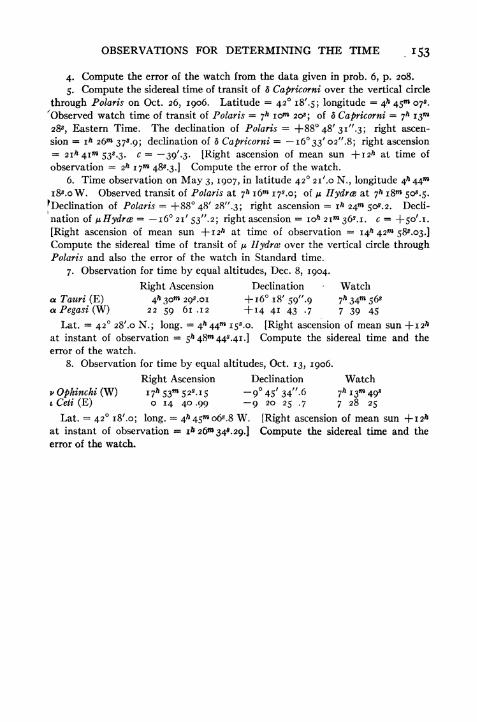
OBSERVATIONS FOR DETERMINING THE TIME 153
4. Compute the error of the watch from the data given in prob. 6, p. 208.
5. Compute the sidereal time of transit of d Capricorni over the vertical circle
through Polaris on Oct. 26, 1906. Latitude = 42 i8'-5; longitude = 4^ 45"* 07*.
'Observed watch time of transit of Polaris = jh 10 20s
;of 5 Capricorni j
hi^m
28s , Eastern Time. The declination of Polaris = +88 48' 3i".s; right ascen-
sion = ih 26 37s .9; declination of 5 Capricorni = i633'o2".8; right ascension
== 21^41^*53^.3. c = 39'.3. [Right ascension of mean sun -\-i2h at time of
observation 2h 17 48*.3.] Compute the error of the watch.
6. Time observation on May 3, 1907, in latitude 42 21'.o N., longitude 4h 44
i8s .o W. Observed transit of Polaris at 7* i6w 17^.0; of AI Hydras at 7** i8m 50*. 5.
^Declination of Polaris +88 48' 28".3; right ascension = i^ 24^ 50^.2. Decli-
nation of fj.Hydr& = 16 21' 53". 2; right ascension = io& 21 36*. i. c = -f SO'.L
[Right ascension of mean sun + 12* at time of observation = 14^ 42"* 585.O3.]
Compute the sidereal time of transit of ^ Hydros over the vertical circle throughPolaris and also the error of the watch in Standard time.
7. Observation for time by equal altitudes, Dec. 8, 1904.
Right Ascension Declination Watcha Tauri (E) 4^30^ 293.01 +16 18' 59^.9 7*34^56*aPegasi(W) 22 59 61.12 +14 4i 43 -7 7 39 45
Lat. = 42 28'.o N.; long.= 4h 44 i$
s .o. [Right ascension of mean sun -f-i2&
at instant of observation = 5^48w 44s.4i.] Compute the sidereal time and the
error of the watch.
8. Observation for time by equal altitudes, Oct. 13, 1906.
Right Ascension Declination Watchv Ophinchi (W) i7^53w 52
s.i5 ~945 /
34"-6 7^i34oi Ceti (E) o 14 40 .99 9 20 25 .7 7 28 25
Lat. = 42 iS'.o; long. = 4^45 06s .8 W. [Right ascension of mean sun -fi2ft
at instant of observation = ia 26m 34.29.] Compute the sidereal time and the
error of the watch.
CHAPTER XII
OBSERVATIONS FOR LONGITUDE
90. Method of Measuring Longitude.
The measurement of the difference in longitude of two places^
depends upon a comparison of the local times of the places at
the same absolute instant of time. One important method
is that in which the timepiece is carried from one station to
the other and its error on local time determined in each place.
The most precise method, however, and the one chiefly used
in geodetic work, is the telegraphic method, in which the local
times are compared by means of electric signals sent through a
telegraph line. Other methods, most of them of inferior accu-
racy, are those which depend upon a determination of the moon's
position (moon culminations, eclipses, occultations) and upon
eclipses of Jupiter's satellites, and those in which terrestrial
signals are employed.
91. Longitude by Transportation of Timepiece.In this method the error of the watch or chronometer with
reference to the first meridian is found by observing the local
time at the first station. The rate of the timepiece should be
determined by making another observation at the same place *
at a later date. The timepiece is then carried to the second
station and its error determined with reference to this meridian.
If the watch runs perfectly the two watch corrections will
differ by just the difference in longitude. Assume that the first
observation is made at the easterly station and the second at
the westerly station. To correct for rate, let r be the daily
rate in seconds, + when losing when gaining, c the watch
correction at the east station, cfthe watch correction at the
west station, d the number of days between the observations,
154

OBSERVATIONS FOR LONGITUDE 155
and T the watch reading at the second observation. Then the
difference in the longitude is found as follows :
Local time at W. station = T + c'
Local time at E. station = T + c + dr
Diff. in time = Diff. in Long. = c + dr c' . [97]
The same result will be obtained if the stations are occupied
in the reverse order.
^ If the error of a mean-time chronometer or watch is found
iby star observations, it is necessary to know the longitudes
accurately enough to correct the sun's right ascension. If a
sidereal chronometer is used and its error found on local sidereal
time this correction is rendered unnecessary.
In order to obtain a check on the rate of the timepiece the
observer should, if possible, return to the first station and again
determine the local time. If the rate is uniform the error in
Jits determination will be eliminated by taking the mean of the
results. This method is not as accurate as the telegraphic
method, but if several chronometers are used and several round
trips between stations are made it will give good results. It is
useful at sea and in exploration surveys.
Example.Observations for local mean time at meridian A indicate
that the watch is 15"* 40* slow. At a point B, west of A, the
watch is found to be 14** 10* slow on local mean time. The
watch is known to be gaining 8* per day. The second obser-
vation is made 48 hours after the first. The difference in longi-
:ude is therefore
+ iSm40*
- 2 X 8* - i4m
10* = im
14*.
The meridian B is therefore im
14* or 18' 30" west of meridian A.
92. Longitude by the Electric Telegraph.
In the telegraphic method the local sidereal time is accurately determined by
^star transits observed at each of the stations. The observations are made with
large portable transits and are recorded on chronographs which are connected
with break-circuit chronometers. The stars observed are selected in such a man-
ner as to permit determining the instrumental errors so that the effect of these
errors may be eliminated from the results. The stars are divided into two groups.

I$6 PRACTICAL ASTRONOMY
Half the number are observed with the axis in one position and the other half with
the axis reversed. This determines the error of the sight lii\e. In each half set
some of the stars are north of the zenith and some south. The differences in times
of transit of these two groups measures the azimuth error. The inclination error
is measured with the striding level. (See Arts. 55 and 77.)
After the corrections to the two chronometers have been accurately determined
the two chronographs are switched into the main-line circuit and signals sent either
by making or breaking the circuit a number of times by the use of a telegraph key.
These signals are recorded on both chronographs. In order to eliminate the error
due to the time of transmission of the signal,* the signals are sent first in the di-
rection E to W and then in the direction W to E. The mean of the two results is!
free from the error provided it is constant during the interval. The personal errors
of the observers are now nearly eliminated by the use of the impersonal transit
micrometer, instead of by exchange of observers, as was formerly done. After all
of the observations have been corrected for azimuth, collimation and level, and the
error of the chronometer on local sidereal time is known, each signal sent over the
main line will be found to correspond to a certain instant of sidereal time at the
east station and a different instant of sidereal time at the west station. The diff-
erence between the two is the difference in longitude expressed in time units.
In the more recent work (since 1922) the longitude of a station is determined with
reference to Washington by receiving the time signal by radio. This cuts the cost
of the work in half since there is but one station to be occupied.
By the telegraph method a longitude difference may be determined with an error
of about QS.OI or about 10 feet on the earth's surface.
93. Longitude by Time Signals.
If it is desired to obtain an approximate longitude for any purpose this may be
done in a simple manner provided the observer is able to obtain the standard time
at some telegraph office or railroad station, or by radio, as given by the noon signal
or the 10^ P.M. signal. He may determine his local mean time by any of the pre-
ceding methods (Chapter XI). The difference between the local time and the
standard time by telegraph or radio is the correction to be applied to the longitude
of the standard meridian to obtain the longitude of the observer.
Example.Altitude of sun, 27 44' 35"; latitude, 42 22' N.; declination, ^oc/oo," N.,
equation of time, -f-3m 48s
.8; watch reading, 4^ i8m 13*. 8. From these data the
local mean time is found to be 4* 33 43^.9, making the watch 15*" 30*. i slow. Bycomparison with the telegraph signal at noon the watch is found to be 6* fast of
Eastern Standard Time. The longitude is then computed as follows:
Correction to L. M. T. = +i5w 30*.!Correction to E. S. T. = -oo 06.0
Difference in Longitude = i$m
36*. i= 354'oi". 5
Longitude = 75-
3 54'.= 71 o6'.o West
* In a test made in 1905 it was found that the time signal sent from Washington
reached Lick Observatory, Mt. Hamilton, CaL, in

OBSERVATIONS FOR LONGITUDE 157
94. Longitude by Transit of the Moon.
A method which is adapted to use with the surveyor's transit and which, although
not precise, may be useful on exploration surveys, is that of determining the moon's
, right ascension by observing its transit over the meridian. The right ascension
of the moon's centre is tabulated in the Ephemeris for every hour of Greenwich
Civil Time; hence if the right ascension can be determined, the Greenwich Civil
Time becomes known. A comparison of this with local time gives the longitude.
The observation consists in placing the instrument in the plane of the meridian
and noting the time of transit of the moon's bright limb and also of several stars
whose declinations are nearly the same as that of the moon. The table of" Moon
i Culminations"
in the Ephemeris shows which limb (I or II) may be observed.
k (See note on p. 159.) The observed interval of time between the moon's transit
and a star's transit (reduced to sidereal time if necessary) added to or subtracted
from the star's right ascension gives the right ascension of the moon's limb. Avalue of the right ascension is obtained from each star and the mean value used.
To obtain the right ascension of the centre of the moon it is necessary to apply to
the right ascension of the edge a correction, taken from the Ephemeris, called"sidereal time of semidiameter passing meridian." In computing this correction
the increase in right ascension during this short interval has been allowed for, so
the result is not the right ascension of the centre at the instant of transit of the
limb, but at the instant of transit of the centre. If the west limb was observed
this correction must be added; if the east limb, it must be subtracted. The result
is the right ascension of the centre at the instant of transit, which is also the local
sidereal time at that instant. Then the Greenwich Civil Time corresponding to
this instant is found by interpolation in the table giving the moon's right ascension
for every hour. To obtain the Greenwich Civil Time by simple interpolation find
the next less right ascension in the table and the"varia. per min." on the same
line; subtract the tabular right ascension from the given right ascension (obtained
from the observation) and divide this difference by the"varia. per min." The
result is the number of minutes (and decimals of minutes) to be added to the tab-
ulated hour of Greenwich Civil Time. If the"varia. per min." is varying rapidly
it will be more accurate to interpolate as follows: Interpolate between the two
values of the"varia. per min." to obtain a "varia. per min." which corresponds
>to the middle of the interval over which the interpolation is carried. In observa-
tions made with a surveyor's transit this refinement is seldom necessary.
In order to compare the Greenwich time with the local time it is necessary to
convert the Greenwich Civil Time into the corresponding instant of Greenwich
Sidereal Time. The difference between this and the local sidereal time is the
longitude from Greenwich.
In preparing for observations of the moon's transit the Ephemeris should be
consulted (Table of Moon Culminations) to see whether an observation can be
made and to find the approximate time of transit. The time of transit may be
obtained either from the Washington civil time of transit or from the Greenwich
civil time in the first part of the Ephemeris. The tabular time must be corrected
for longitude. The apparent altitude of the moon should be computed and allow-

158 PRACTICAL ASTRONOMY
ance made for parallax. The moon's parallax is so large that the moon would not
be in the field of view if this correction were neglected. The horizontal parallax
multiplied by the cosine of the altitude is the required correction. The moon will
appear lower than it would if seen from the centre of the earth. The correction is
therefore subtractive.
Since the moon increases its right ascension about 2* in every im of time it is
evident that any error in determining the right ascension will produce an error
about thirty times as great in the longitude, so that this method cannot be made to
give very precise results. It has, however, one great advantage. If for any reason,
such as an accident to the timepiece, a knowledge of the Greenwich time is com*
pletely lost, it is still possible by this method to recover the Greenwich time with
a fair degree of accuracy.
Following is an example of an observation for longitude by the method of moonculminations made with an engineer's transit.
Example.Observed transit of moon's west limb July 30, 1925, for longitude. Watch time
of transit moon's west limb, 7^ 27** 14*; transit of <r Scorpii, 7* 29^ 20s .
43^.56 = local sidereal time
From Ephemeris
July 31 Gr. Civ. T. Rt. Asc. Moon Varia. per Min.o* 16* i4 375.54 2.3986i 16 17 01 .64 2.4049
2m 245.10 63
.
i o6.02 = 66X02 log 1.81968 .33-0 x 63 = 14Interpolated varia. per min. = 2.4000 log 0.38021 144.1
= 27 3o*.s
G. C. T. = o 27 3o.soas + i2& = 20 32 23 .49Table III 04.52
Gr. Sid. T. 20* 59 s8*.5iLoc. Sid. T. 16 15 43-56
Longitude 4* 44W i4*-95 W. = 71 03' 457/ W:

OBSERVATIONS FOR LONGITUDE IS9
NOTE. It has already been stated that the moon moves eastward on the celes-
tial sphere at the rate of about 13 per day; as a result of this motion the time of
meridian passage occurs about 51"* later (on the average) each day. On account
of the eccentricity of its orbit, however, the actual retardation may vary consid-
erably from the mean. The moon's orbit is inclined at an angle of about 5 08'
to the plane of the earth's orbit. The line of intersection of these two planes ro-
tates in a similar manner to that described under the precession of the equinoxes,
except that its period is only 19 years. The moon's maximum declination, there-
fore, varies from 23 27' -f 5 08' to 23 27'-
5 08', that is, from 28 35' to 18 19',
First Quarter Last Quarter
c
oFull Moon
FIG. 64. THE MOON'S PHASES
according to the relative position of the plane of the moon's orbit and the plane of
the equator. The rapid changes in the relative position of the sun, moon, and earth,
and the consequent changes in the amount of the moon's surface that is visible
from the earth, cause the moon to present the different aspects known as the
moon's phases. Fig. 64 shows the relative positions of the three bodies at several
different times in the month. The appearance of the moon as seen from the earth
is shown by the figures around the outside of the diagram.
It may easily be seen from the diagram that at the time of first quarter the
moon will cross the meridian at about 6 P.M.; at full moon it will transit at mid-

160 PRACTICAL ASTRONOMY
night; and at last quarter it will transit at about 6 A.M. Although the part of the
illuminated hemisphere which can be seen from the earth is continually changing,
the part of the moon's surface that is turned toward the earth & always the same,
because the moon makes but one rotation on its axis in one lunar month. Nearly
half of the moon's surface is never seen from the earth.
Questions and Problems
1. Compute the longitude from the following observed transits: (0 Aquarii,
5& i6m 04 P.M.; TT Aquarii, 5* 24 40$; moon's west limb, 5^ 32 27*; X Aquarii,
5* 5im 47s . Right ascensions; Aquarii, 22h nm 27^.6; TT Aquarii, 22h 2om 04*.6;
X Aquarii, 22h 47 i8.3. The sidereal time of semi-diameter passing meridian
= 60*.3. At Gr. Civ. T. 22h the moon's right ascension was 22^ 27"* 53^.3. The
varia. per min. = is.98oo. The right ascension of the mean sun +12^ = 4^ 36
29*. 7.
2. Which limb of the moon can be observed for longitude by meridian transit
if the observation is taken in the morning?
3. At about what time (local civil) will the moon transit when it is at first
quarter?
4. The sun's corrected altitude is 57 15' 36"; latitude, 42 22' N.; corrected
decimation, 18 58'.6 N,; corrected equation of time, 4-3 49s .o; watch reading,
ih 2Qm o8s,P.M. Error of watch on Eastern Standard time by noon signal is lo5
(fast). Compute the'longitude.
5. On April 2, 1925 the transit of Hydrce is observed; watch reading 7* 52 31^
P.M. At IO& P.M. E. S. T. the radio signal shows that the watch is 3* fast. The
right ascension of the sun -f-i2* at cfl G. C. T. April 2, 19^5, is 12^39 i65.82j
on April 3, it is 12^ 43 i3s,38. Compute the longitude.

CHAPTER XIII
OBSERVATIONS FOR AZIMUTH
95. Determination of Azimuth.
^
The determination of the azimuth of a line or of the direction
l of the true meridian is of frequent occurrence in the practice of
the surveyor and is probably the most important to him of all
the astronomical observations. In geodetic surveys, in which
triangulation stations are located by means of their latitudes
and longitudes, the precise determination of astronomical po-sition is of as great importance as the orientation; but in general
engineering practice, in topographical work, etc., the azimuth
observation is the one that is most frequently required.
Too much stress cannot be laid on the desirability of employ-
ing the true meridian and true azimuths for all kinds of surveys.
The use of the magnetic meridian or of an arbitrary reference
line may save a little trouble at the time but is likely to lay uptrouble for the future. As surveys are extended and connected
and as lines are re-surveyed the importance of using the true
meridian becomes greater and greater.
96. Azimuth Mark.
When an observation is made at night it is frequently incon-
venient or impossible to sight directly at the object whose azimuth
is to be determined; it is necessary in such cases to determine
the azimuth of a special azimuth mark, which can be seen both
at night and in the day, and then to measure the angle between
this mark and the first object during the day. The azimuth
mark usually consists of a lamp or a lantern placed inside a box
having a small hole cut in the side through which the light maybe seen. The size of the opening will vary with the distance,
power of telescope, etc.; for accurate work it should subtend
an angle not much greater than o".s to i".o. If possible the
161

162 PRACTICAL ASTRONOMY
mark should be placed so far away that the focus of the tele-
scope will not have to be altered when changing from the star
to the mark. For a large telescope of high power the distance
should be a mile or so, but for surveyor's transits it may be
much less; and in fact the topography around the station maybe such that it is impossible to place the mark as far away as is
desirable.
97. Azimuth of Polaris at Greatest Elongation.
The 1
simplest method of determining the direction of the
meridian with accuracy is by means of an observation of the
FIG. 65. CONSTELLATIONS NEAR THE NORTH POLE. POLARIS AT
WESTERN ELONGATION
polestar, or any other close circumpolar, when it is at its greatest
elongation. (See Art. 19, p. 36.) The appearance of the
constellations at the time of this observation on Polaris may be
seen by referring to the star map (Fig. 55) and Fig. 65. Whenthe polestar is west of the pole the Great Dipper is on the right
and Cassiopeia on the left. The exact time of elongation maybe found by computing the sidereal time when the star is at
elongation and changing this into local civil time and then into
standard time, by the methods of Arts. 37 and 32.
To find the sidereal time of elongation first compute the
hour angle (te) by Equa. [35] and express it in hours, minutes and
seconds. If western elongation is desired, te is the hour angle;

OBSERVATIONS FOR AZIMUTH
Zenith
Eastern Elongation
if eastern elongation is desired, 24* te is the hour angle. The
sidereal time is then found by adding the hour angle to the
right ascension. An average
value for te for Polaris for
latitudes between 30 and
50 is about s* 56 of sidereal
time, or 5" 55 of mean time;
this is sufficiently accurate
for a rough estimate of the
time of elongation, and as
it changes but little from
year to year and in differ- We8tecnEiongatio j
ent latitudes, it may be used
instead of the exact value for
many purposes. Approxi-
mate values of the times of
elongation of Polaris may be
taken from Table V.
Example. Find the East-
ern Standard time of western
elongation of Polaris on April
25, 1925, in latitude 42 22'
N., longitude 7 1 06' W. The
right ascension of Polaris is
i*33m27
s
.i5; the declination is +88 54' 04".54. The right
ascension of the mean sun +12" at o* G. C. T. =14" 09 57*. 54;
corrected for longitude it is 14* iow 44*. 26.
log tan <= 9.96002 te = 5* S5
m57*-45 S =
7* 29** 22*.6o
log tan 5 = 1.71717 a = i 33 27 .15 as + 12* = 14 10 44 .26
log cos te = 8.24285 S 7h2gm 22s
.60 Sid. int. =17* i8w 38^.34te = 88 59' 5i".7 Table II = 2 50.16=
5 55*55*45 Loc. Civ. T. = 17* 15* 48*.i8
Long. diff. = 15 36 .00
E. S. T. (civil) ==17* oo I2*.i8
The transit should be set in position half an hour or so before
elongation. The star should be bisected with the vertical cross
FIG. 66

164 PRACTICAL ASTRONOMY
hair and, as it moves out toward its greatest elongation, its
motion followed by means of the tangent screw of the upper or
lower plate. Near the time of elongation the star will appearto move almost vertically, so that no motion in azimuth can be
detected for five minutes or so before or after elongation. About
5W before elongation, centre the plate levels, set the vertical hair
carefully on the star, lower the telescope without disturbing its
azimuth, and set a mark carefully in line at a distance of several
hundred feet north of the transit. Reverse the telescope, re-
centre the levels if necessary, bisect the star again, and set an-
other point beside the first one. If there are errors of adjust-
ment (line of collimation and horizontal axis) the two points
will not coincide; the mean of the two results is the true point.
The angle between the meridian and the line to the stake (star's
azimuth) is found by the equation
sin Zn sin p sec $ [36]
where Zn is the azimuth from the north (toward the east or the
west); p, the polar distance of the star; and 0, the latitude of
the place. The polar distance may be obtained by taking the
declination from the Ephemeris and subtracting it from 90;or, it may be taken from Table E if an error of 30" is permissible
The latitude (0) may be taken from a map or found by obser-
vation. (Chap. X.) The latitude does not have to be known
with great precision; a differentiation of [36] will show that an
error of i' in causes an error of only about
for latitudes within the United States.
"in Zn for Polaris
TABLE E
MEAN POLAR DISTANCE OF POLARIS
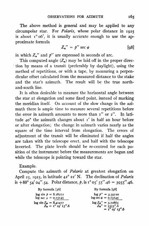
OBSERVATIONS FOR AZIMUTH 165
The above method is general and may be applied to any
circumpolar star. For Polaris, whose polar distance in 1925
is about io6', it is usually accurate enough to use the ap-
proximate formula
Zw" = p" sec * [98]
in which Zw"and p" are expressed in seconds of arc.
This computed angle (ZJ may be laid off in the proper direc-
tion by means of a transit (preferably by daylight), using the
method of repetitions, or with a tape, by measuring a perpen-
dicular offset calculated from the measured distance to the stake
and the star's azimuth. The result will be the true north-
and-south line.
It is often desirable to measure the horizontal angle between
the star at elongation and some fixed point, instead of markingthe meridian itself. On account of the slow change in the azi-
muth there is ample time to measure several repetitions before
the error in azimuth amounts to more than i" or 2". In lati-
tude 40 the azimuth changes about i' in half an hour before
or after elongation; the change in azimuth varies nearly as the
square of the time interval from elongation. The errors of
adjustment of the transit will be eliminated if half the angles
are taken with the telescope erect, and half with the telescope
inverted. The plate levels should be re-centred for each po-
sition of the instrument before the measurements are begun and
while the telescope is pointing toward the star.
Example.
Compute the azimuth of Polaris at greatest elongation on
April 25, 1925, in latitude 42 22' N. The declination of Polaris
is +88 54' 04".54. Polar distance, p, is i 05' 55".46 3955"-46.
By formula [36] By formula [98]
log sin p - 8.28272 log p" = 3.59720log sec <p
= 0.13145 log sec <= 0.13145
log sinZfi ~ 8.41417 logZw" = 3.72865
Zn - i 29' i3"-6 Z" = 5353"-6- x* 29' i3".6

166 PRACTICAL ASTRONOMY
If the mark set in line with the star is 630.0 feet away from the
transit the perpendicular offset to the meridian is "calculated as
follows:
log 630.00 =2.79934
log tan Zn = 8.41432
Jog offset = 1.21366offset = 16.355 ft-
98. Observations Near Elongation.
If observations are made on a close circumpolar star within
a few minutes of elongation the azimuth of the star at the
instant of pointing may be reduced to its value at elongation if
the time of the observation is known. The formula for com-
puting the correction is
C =112.5 X 3600 X sin i" X tanZ, X (T - Tey [99]
in which Ze is the azimuth at greatest elongation, T is the ob-
served time and Te the time of elongation. T Te must be
expressed in sidereal minutes. The correction is in seconds of
angle. Values of this correction are given in Table Va in the
Ephemeris for each minute up to 25, or in Table VI of this book.
Example.The horizontal angle from a mark to the right to Polaris is 2 37' 30", the watch
reading 6^ 28 00s when the star was sighted. The watch time of western elonga-
tion is o7* 04 00s. The azimuth of Polaris at elongation is i 37' 48". The cor-
rection corresponding to a 24"* mean time interval, or a 24"* 04* sidereal interval,
is 32". The horizontal angle from the mark to the elongation position of the star
is 2 37' 30" 32" = 2 36' 58". The bearing of the mark is the sum of this and
the azimuth at elongation, or 2 36' 58" + i 37' 48" = 4 14' 46". The bearingis therefore N. 4 14' 46" W.
99. Azimuth by Elongations in the Southern Hemisphere.The method described in the preceding article may be applied
to stars near the south pole, but since there are no bright stars
within about 20 of the pole the observation is not quite so
simple and the results are somewhat less accurate. As the polar
distance increases the altitude of the star at elongation increases
and the diurnal motion becomes more rapid. The increase in
altitude causes greater inconvenience in making the pointings
and also magnifies the effect of instrumental errors. On account

OBSERVATIONS FOR AZIMUTH 167
of the rapid motion of the star it is important to know before-
hand both the time at which elongation will occur and the
altitude of the star at this instant.
The time of elongation is computed as explained for Polaris
in Art. 91. The altitude may be found by the formula
.,
sin .,sm h = -72- = sm <j> sec p.sm 5
There is usually time enough to reverse the transit and make
one observation in each position of the axis, without serious
error, if the first is taken when the star is 10' to 15' below eastern
elongation, or the same amount above western elongation.
Example.Mean observed horizontal angle between mark and a. Triang. Austr. at Eastern
elongation May 31, 1920 = 35 10' 30". (Mark E. of star.) Decl. a Triang.
Austr. = -6853'n"; right ascension = i6> 40 18^.5. Lat. = -3435/
(S.)j
Long. = 58 25' W.The time and altitude are computed as follows:
log tan <f>= 9.83849 log sin = 9.75405
log tan 5 = 0.41326 log sin 5 = 9.96982
log cos te 9.42523 log sin h = 9.78423
36o-
te= 74 33'-6 h = 37 28'.;
24^ te 4^ 58 14*.4te= 19 01 45 .6
a 16 40 18 .5
S = 1 1^42 04*. i
The local civil time corresponding to nh 42 04*. i is 19^ 05 3 2s . 5.
For the azimuth of the star and the resulting bearing of the mark we have
log cos 5 = 9-55657
log cos <f>- 9.91556
log sin Z = 9.64101Z * 25 56'.8 (East of South)
Measured angle = 35 10 .5
Bearing of mark S 61 O7'.3 E
ioo. Azimuth by an Altitude of the Sun.
In order to determine the azimuth of a line by means of an
observation on the sun the instrument should be set up over
one of the points marking the line and carefully levelled. The
plate vernier is first set at o and the vertical cross hair sighted
on the other point marking the line. The colored shade glass

i68 PRACTICAL ASTRONOMY
is then screwed on to the eyepiece, the upper clamp loosened,
and the telescope turned toward the sun. The sun's disc should
be sharply focussed before beginning the
observations. In making the pointings
on the sun great care should be taken
not to mistake one of the stadia hairs
for the middle hair. If the observation
is to be made, say, in the forenoon (in,
the northern hemisphere), first set the
FIG. 67. POSITION OFcross hairs so that the vertical hair is
SUN'S Disc A FEW SECONDS tangent to the right edge of the sun andBEFORE OBSERVATION , , , i i a n
(A.M. observation in Northern the horizontal hair cuts off a small seg-Hemisphere.)
(Fig. 67.)* The arrow in the figure shows the direction of the
sun's apparent motion. Since the sun is now rising it will
in a few seconds be tangent to the horizontal hair. It is only
necessary to follow the right edge bymeans of the upper plate tangent screw
until both cross hairs are tangent. At
this instant, stop following the sun's
motion and note the time. If it is de-
sired to determine the time accurately,
so that the watch correction may be
found from this same observation, it can FlG 68 posmON OF
be read more closely by a second ob- SUN'S Disc A FEW SECONDS_ . . , . -
,. BEFORE OBSERVATION
server. Both the horizontal and the (A .M . observation in Northern *
vertical circles are read, and both anglesHemisphere.)
and the time are recorded. The same observation may be re-
peated three or four times to increase the accuracy. The instru-
ment should then be reversed and the set of observations repeated,
except that the horizontal cross hair is set tangent to the upper
edge of the sun and the vertical cross hair cuts a segment from
the left edge (Fig. 68). The same number of pointings should
* Tn the diagram only a portion of the sun's disc is visible; in a telescope of low
power the entire disc can be seen.
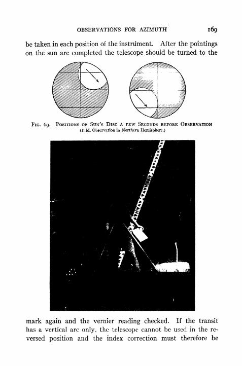
OBSERVATIONS FOR AZIMUTH 169
be taken in each position of the instrument. After the pointings
on the sun are completed the telescope should be turned to the
FIG. 69. POSITIONS OF SUN'S Disc A FEW SECONDS BEFORE OBSERVATION(P.M. Observation in Northern Hemisphere.)
mark again and the vernier reading checked. If the transit
has a vertical arc only, the telescope cannot be used in the re-
versed position and the index correction must therefore be
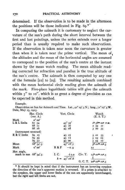
PRACTICAL ASTRONOMY
determined. If the observation is to be made in the afternoon
the positions will be those indicated in Fig. 69.**
In computing the azimuth it is customary to neglect the cur-
vature of the sun's path during the short interval between the
first and last pointings, unless the series extends over a longer
period than is usually required to make such observations.
If the observation is taken near noon the curvature is greater
than when it is taken near the prime vertical. The mean of.
the altitudes and the mean of the horizontal angles are assumed
to correspond to the position of the sun's centre at the instant
shown by the mean watch reading. The mean altitude read-
ing corrected for refraction and parallax is the true altitude of
the sun's centre. The azimuth is then computed by any one
of the formulae [22] to [29]. The resulting azimuth combined
with the mean horizontal circle reading gives the azimuth of
the mark. Five-place logarithmic tables will give the azimuth
within 5" to 10", which is as great a degree of precision as can
be expected in this method.
Example.Observation on Sun for Azimuth and Time. Lat., 42 29'^ N. ; long., 71 07'.$ W.
Date, May 25, 1925.
* It should be kept in mind that if the instrument has an inverting eyepiecethe direction of the sun's apparent motion is reversed. If a prism is attached to
the eyepiece, the upper and lower limbs of the sun are apparently interchanged,but the right and left limbs are not.

OBSERVATIONS FOR AZIMUTH 171
Sun's decl. at o* = +20 48' 55^,8-j-27".6o x 20&.02 = +9 12 .6
6 = -f-2o58'o8".4
N
If it is desired to compute the time
from the same observation it may be
found by formula [12], by [19], or bythose derived on p. 174. The resultingEastern standard time is 3^ 000*42*. 7,
making the watch 27^.6 fast. (The equa-tion of time at 20^ Gr. Civ. T. is -j-3
1*
FIG. 70
If for any reason only one limb of the sun has been observed,the azimuth observed may be reduced to the centre of the sun
by applying the correction s sec h, where s is the semidiameterand h is the altitude of the centre.
The following examples and explanations are taken from Serial
166, U. S. Coast and Geodetic Survey, and illustrate the methodof observing for azimuth and longitude with a small theod-
olite as practised on magnetic surveys.
Having leveled and adjusted the theodolite and selected asuitable azimuth mark, a well-defined object nearly in the
horizon and more than 100 yards distant, the azimuth ob-
servations are made in the following order, as shown in the
sample set given on pages 172 and 173.
Point on the mark with vertical circle to the right of the
telescope (V.C.R.) and read the horizontal circle, verniers Aand B. Reverse the circle, invert the telescope and point onthe mark again, this time with vertical circle left (V.C.L.).Place the colored glass in position on the eyepiece and point onthe sun with vertical circle left, bringing the horizontal andvertical cross wires tangent to the sun's disc. At the momentwhen both cross wires are tangent note the time by the chro-
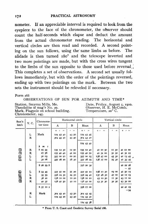
PRACTICAL ASTRONOMY
nometer. If an appreciable interval is required to look from the
eyepiece to the face of the chronometer, the observer should
count the half-seconds which elapse and deduct the amount
from the actual chronometer reading. The horizontal and
vertical circles are then read and recorded. A second point-
ing on the sun follows, using the" same limbs as before. The
alidade is then turned 180 and the telescope inverted and
two more pointings are made, but with the cross wires tangent
to the limbs of the sun opposite to those used before reversal, \
This completes a set of observations. A second set usually fol-
lows immediately, but with the order of the pointings reversed,
ending up with two pointings on the mark. Between the two
sets the instrument should be releveled if necessary.
Form 266
OBSERVATIONS OF SUN FOR AZIMUTH AND TIME*
Station, Smyrna Mills, Me.Theodolite of mag'r No. 20.
Mark, Flagpole on school building.Chronometer, 245.
Date, Friday, August 5, 1910.Observer, H. E. McComb.Temperature, 20 C.
From U. S. Coast and Geodetic Survey Serial 166.

OBSERVATIONS FOR AZIMUTH 173
The chronometer and circle readings for the four pointings of a
set are combined to get mean values for the subsequent compu-tation. When the vertical circle is graduated from zero to 360,the readings with vertical circle right give the apparent altitude
of one limb of the sun, while those with vertical circle left mustbe subtracted from 180 to get the apparent altitude of the other
limb. The mean of the four pointings gives the apparent alti-
tude of the sun's center. This must be corrected for refraction
'and parallax to get the true altitude.
Form 266
OBSERVATIONS OF SUN FOR AZIMUTH AND TIME*
Station, Smyrna Mills, Me.Theodolite of mag'r No. 20.
Mark, Flagpole on school building.Chronometer, 245.
Date, Friday, August 5, 1910.Observer, H. E. McComb.Temperature, 21 C.
* From U. S. Coast and Geodetic Survey Serial 166.
It is important to test the accuracy of the observations as
soon as they have been completed, so that additional sets maybe made if necessary. This may be done by comparing the

174 PRACTICAL ASTRONOMY
mean of the first and fourth pointings of a set with the mean of
the second and third, or by comparing the rate of change in the
altitude and azimuth of the sun between the first and second
pointings, the third and fourth, fourth and fifth, fifth and sixth,
and seventh and eighth. For the period of 15 or 20 minutes
required for two sets of observations the rate of motion of the
sun does not change much.
COMPUTATION
From formula [24] we have
Zcot2 = sec 5 sec (s p) sin (s </>) sin (s h)
2
and from [19],
tan - = i/( cos 5 sin (s h) esc (s <t>) sec (s p)j
// cos s cos (s p) sin2(s K)\"
V \sin (s-
</>) sin (s-
h)
'
cos2(s- p))
Z= tan - sin (s h) sec (s p).2
The angle Zs is the azimuth of the sun from the south point,
east if in the morning, west if in the afternoon.
The form of computation is shown in the following example,
for the sets of observations at Smyrna Mills, Me., given above.
The different steps of the computation are most conveniently
made in the following order: .
Enter the corrected altitude, mean readings of the horizontal
circle for the pointings on the sun and on the mark, and the
chronometer time for each set of observations in their proper
places. Enter the value of latitude obtained from the latitude
observations or other source. Compute the chronometer cor-
rection on standard time for the time of each set of observations
from the comparisons with telegraphic time signals. Unless
the chronometer has a large rate its correction may be taken the
same for two contiguous sets of observations. Compute the
Greenwich time of observation for each set, and find from the
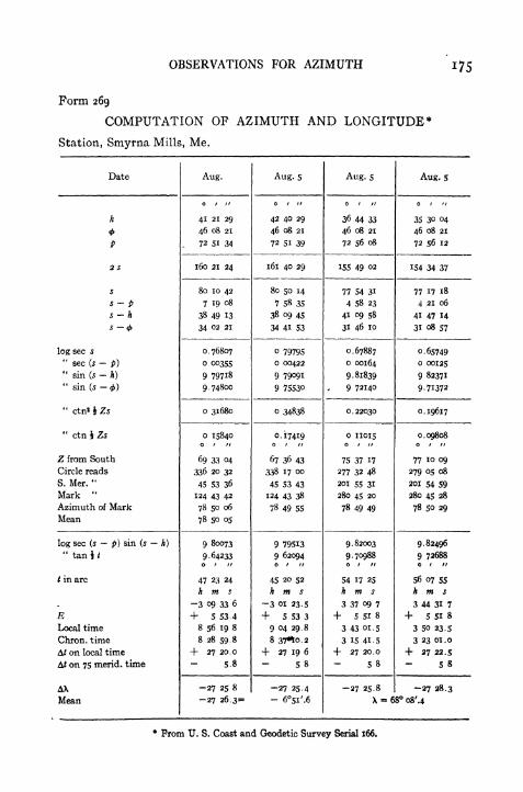
OBSERVATIONS FOR AZIMUTH 175
Form 269
COMPUTATION OF AZIMUTH AND LONGITUDE*
Station, Smyrna Mills, Me.
* From U. S. Coast and Geodetic Survey Serial 166,

1 76 PRACTICAL ASTRONOMY
American Ephemeris, or the Nautical Almanac, the sun's polar
distance and the equation of time for that time" as previously
explained. The succeeding steps require little explanation.
As the horizontal circles of theodolites are with few exceptions
graduated clockwise, and as the sun is east of south in the
morning and west of south in the afternoon, it follows that in
order to find the horizontal circle reading of the south point,
the azimuth of the sun must be added to the circle reading of
the sun for the morning observations and subtracted from it'
for the afternoon observations. The horizontal circle reading
of the south point subtracted from the mark reading gives the
azimuth of the mark, counted from south around by west from
o to 360.For the computation of /, the logarithms of sec (s p) and
sin (s h) are found in the azimuth computation and their
sum can be written down in its proper place. From that must
be subtracted log ctn ^ Zs to find log tan \ /. The correspond-
ing value of i is the time before or after apparent noon. If in
the case of the morning observations ctn \ ti be substituted for
tan 4 /, /i will be counted from midnight. The difference be-
tween the chronometer correction on local mean time and the
correction on standard time is the difference in longitude be-
tween the standard meridian and the place of observation.
101. Observations in the Southern Hemisphere.In making observations on the sun for azimuth in the southern
hemisphere (latitude greater than declination) the pointings would
be made on the left and lower limbs and on the right and upperlimbs in the forenoon, and on the right and lower and on the
left and upper limbs in the afternoon, as indicated in Fig. 71.
If the instrument has no vertical and horizontal hairs but has
cross hairs of the X pattern the sun's image may be placed in
any two symmetrical positions instead of those indicated above.
The same formulae used for the northern hemisphere may be
adapted to the southern hemisphere either by considering the
latitude < as negative and employing the regular forms, or by
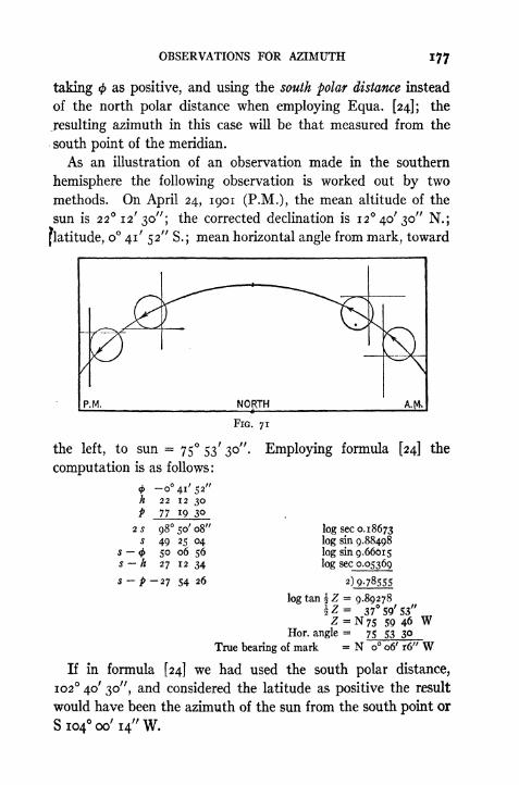
OBSERVATIONS FOR AZIMUTH 177
taking as positive, and using the south polar distance instead
of the north polar distance when employing Equa. [24]; the
resulting azimuth in this case will be that measured from the
south point of the meridian.
As an illustration of an observation made in the southern
hemisphere the following observation is worked out by two
methods. On April 24, 1901 (P.M.), the mean altitude of the
sun is 22 12' 30"; the corrected declination is 12 40' 30" N.;
[latitude,o 41' 52" S.; mean horizontal angle from mark, toward
P.M. NORTH
FIG. 71
the left, to sun =75 53' 30".
computation is as follows:
Employing formula [24] the
-oVsa"22 12 3077 19 30
98 50' 08"
49 25 0450 06 56
27 12 34
s- p-2i 54 26
2 S
S
S (f>
s-h
log sec o.i8673log sin 9.88498
log sin 9.66615log sec 0.05369
2)9-78555
log tan \ Z - 9.89278\Z= 37 59' 53"Z = N 75 59 46 W
Hor. angle = 75 53 30
True bearing of mark = N o 06' r6" WIf in formula [24] we had used the south polar distance,
102 40' 30", and considered the latitude as positive the result
would have been the azimuth of the sun from the south point or
Sio4 oo'i4"W.

178 PRACTICAL ASTRONOMY
If formula [25] is employed we may take <t> positive, reverse
the sign of 6 and obtain the bearing of the sun from the south.
nat sin 5 == 0.21942log sin = 8.08558
log sink = 9-57746sum = 7.66304
nat sin <f> sin h 0.00460numerator = 0.22402
log numerator = 9.35029 n
log sec <f>= 0.00003
log sec h = 0.03348
log cos Zs~
9.38380 nZs = S 104 oo' 15" W
Measured angle] 75 53 30
True Bearing of Mark = S 179 53' 45" Wor N o 06' 15" W
In this case it would have been quite as simple to solve [25]
in its original form, obtaining the bearing from the north point.
If the south latitude is greater than the sun's declination (say,
lat. 40 S., decl. 20 S.) then the method used in the examplewould be preferable.
102. Most Favorable Conditions for Accuracy.
From an inspection of the spherical triangle Pole Zenith
Sun, it may be inferred that the nearer the sun (or other observed
body) is to the observer's meridian the less favorable are the
conditions for an accurate determination of azimuth from a
measured altitude. At the. instant of noon the azimuth becomes
indeterminate. Also, as the observer approaches the pole the
accuracy diminishes, and when he is at the pole the azimuth is
indeterminate.
To find from the equations the error in Z due to an error in h
differentiate Equa. [13], regarding h as the independent variable;
the result is
(A7 \cos h sin Z cosZ sin h
)dh /
= sin < cos h cos c
= cos 5 cos S by [14]
or, cos <t> cos h sin Z = sin < cos h cos cos Z sin htin

OBSERVATIONS FOR AZIMUTH 179
. dZ cos 8 cos Sdh cos cos h sin Z
cos S
,which by [15]
sin 5 cos h'
= I[102]
cos h tan S
If the declination of the body is greater than the latitude (and1 in the same hemisphere) there will be an elongation, and at this
point the angle 5 (at the sun or star) will be 90; the error dZ
will therefore be zero. For objects whose declinations are such
that an elongation is possible it is clear that this is the most
favorable position for an accurate determination of azimuth
since an error in altitude has no effect upon Z.
If the declination is less than the latitude, or is in the opposite
hemisphere, the most favorable position will depend partly
upon 5, partly upon h. From Equa. [15] it is seen that the maxi-
mum value of 5 occurs simultaneously with the maximum value
of Z, that is, when the body is on the prime vertical (Z = 90
or 270). To determine the influence of h suppose that there
are two positions of the object, one north of the prime vertical
and one south of it, such that the angle S is the same for the two.
The minimum error (dZ) will then occur where cos h is greatest;
this corresponds to the value of h which is least, and therefore,
on the side of the prime vertical toward the pole. The exact
position of the body for greatest accuracy could be found for
'any particular case by differentiating the above expression and
placing it equal to zero.
To find the error in the azimuth due to an error in latitude
differentiate [13] with respect to d$. This gives
(jrrV
cos<sinZ- cosZsin<Hd<t> )
= sin h cos < cos k c<
= cos S cos t by [16]
or cos h cos q> sinZ = sin h cos < cos h cos Z sina<t>
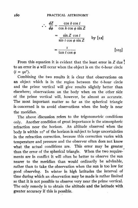
l8o PRACTICAL ASTRONOMY
d? __ COS d COS /
d<t> cos h cos 4> sin Z
= sin Z cos t
sin / cos < sin Z, r ,
tan
From this equation it is evident that the least error in Z due ]
to an error in <j> will occur when the object is on the 6-hour circle
=90).^
Combining the two results it is clear that observations on
an object which is in the region between the 6-hour circle
and the prime vertical will give results slightly better than
elsewhere; observations on the body when on the other side
of the prime vertical will, however, be almost as accurate.
The most important matter so far as the spherical triangle
is concerned is to avoid observations when the body is near
the meridian.
The above discussion refers to the trigonometric conditions
only. Another condition of great importance is the atmospheric
refraction near the horizon. An altitude observed when the
body is within 10 of the horizon is subject to large uncertainties
in the refraction correction, because this correction varies with
temperature and pressure and the observer often does not know
what the actual conditions are. This error may be greater
than the error of the spherical triangle. When the two require-
ments are in conflict it will often be better to observe the sun
nearer to the meridian than would ordinarily be advisable,
rather than to take the observation when the sun is too low for
good observing. In winter in high latitudes the interval of
time during which an observation may be made is rather limited
so that it is not possible to observe very near the prime vertical.
The only remedy is to obtain the altitude and the latitude with
greater accuracy if this is possible.

OBSERVATIONS FOR AZIMUTH l8l
103. Azimuth by an Altitude of a Star near the Prime Vertical.
The method described in the preceding article applies equally
^well to an observation on a star, except that the star's imageis bisected with both cross hairs and the parallax and semi-
diameter corrections become zero. The declinatioh of the star
changes so little during one day that it may be regarded as
constant, and consequently the time of the observation is not
required. Errors in the altitude and the latitude may be par-
tially eliminated by combining two observations, one on a star
about due east and the other on one about due west.
Example.Mean altitude of Regulus (bearing east) on Feb. n, 1908, is 17 36'.8. Latitude^
42 21' N. The right ascension is ioft 03 293.1 and the declination is -j-i2 24' 57".
Compute the azimuth and the hour angle.
= 42 21' log sec = 0.13133^ = *7 33 -8 log sec = 0.02073
cos .90788 <j> h 24 47'. 2
sm - 2I 502 6 = 4-12 25 .o
c s .69286 log= 9.84065
log vers Zn = 9.99271Zn = 89 oa'.S
The star's bearing is therefore N 89 02'.8 E.
To obtain the time we may employ formula [12],
log sin Zn = 9-99994log cos h = 9.97927log sec 5 = 0.01028
log sin t = 9.98949t = -77 26'.7=
5* 09 46*. 7 (east)
Right ascension 10 03 29 .1
Sidereal time = 4^ 53 42*4
104. Azimuth Observation on a Circumpolar Star at any Hour Angle.
The most precise determination of azimuth may be made by measuring the
horizontal angle between a circumpolar star and an azimuth mark, the hour angle
of the star at each pointing being known. If the sidereal time is determined
accurately, by any of the methods given in Chapter XI, the hour angle of the star
may be found at once by Equa. [37] and the azimuth of the star at the instant
may be computed. Since the close circumpolar stars move very slowly and
errors in the observed times will have a small effect upon the computed azimuth,it is evident that only such stars should be used if precise results are sought. The
advantage of observing the star at any hour angle, rather than at elongation, is
182 PRACTICAL ASTRONOMY
that the number of observations may be increased indefinitely and greater accuracy
thereby secured.
The angles may be measured either with a repeating instrument (like the en-
gineer's transit) or with a direction instrument in which the circles are read with
great precision by means of micrometer microscopes. For refined work the instru-
ment should be provided with a sensitive striding level. If there is no striding
level provided with the instrument* the plate level which is parallel to the hori-
zontal axis should be a sensitive one and should be kept well adjusted. At all
places in the United States the celestial pole is at such high altitudes that errors
in the adjustment of the horizontal axis and of the sight line have a comparatively
large effect upon the results. 1
The star chosen for this observation should be one of the close circumpolar stars
given in the circumpolar list in the Ephemeris. (See Fig. 72.) Polaris is the only
bright star in this group and should be used in preference to the others when it is
practicable to do so. If the time is uncertain and Polaris is near the meridian,
in which case the computed azimuth would be uncertain, it is better to use 51
CepheiJ because this star would then be near its elongation and comparatively
large errors in the time would have but little effect upon the computed azimuth.
If a repeating theodolite or an ordinary transit is used the observations consist
in repeating the angle between the star and the mark a certain number of times
and then reversing the instrument and making another set containing the same
number of repetitions. Since the star is continually changing its azimuth it
is necessary to read and record the time of each pointing on the star with the
vertical cross hair. The altitude of the star should be measured just before and
again just after each half-set so that its altitude for any desired instant may be
obtained by simple interpolation. If the instrument has no striding level the
cross-level on the plate should be recentred before the second half-set is begun.
If a striding level is used the inclination of the axis may be measured, while the
telescope is pointing toward the star, by reading both ends of the bubble, with the
level first in the direct position and then in the reversed position.
In computing the results the azimuth of the star might be computed for each
of the observed times and the mean of these azimuths combined with the mean
* The error due to inclination of the axis may be eliminated by taking half of
the observations direct and half on the image of the star reflected in a basin of
mercury.
t 51 Cephei may be found by first pointing on Polaris and then changing the
altitude and the azimuth by an amount which will bring 51 Cephei into the field.
The difference in altitude and in azimuth may be obtained with sui'cient accuracy
by holding Fig. 72 so that Polaris is in its true position with reference to the me-
ridian (as indicated by the position of 8 Cassiopeice) and then estimating the dif-
ference in altitude and the difference in azimuth. It should be remembered that
the distance of 51 Cephei east or west of Polaris has nearly the same ratio to the
difference in azimuth that the polar distance of Polaris has to its azimuth at elon-
gation, i.e., i to sec #.

OBSERVATIONS FOR AZIMUTH
of the measured horizontal angles. The labor involved in this process is so great,
however, that the common practice is first to compute the azimuth corresponding
to the mean of the observed times, and then to correct this result for the effect of
the curvature of the star's path, i.e., by the difference between the mean azimuth
and the azimuth at the mean of the times.
XVIII*
51 Cephei
XII
FIG. 72
For a precise computation of the azimuth of the star formula [32] may be used,
~ _ sin/ , ,
ncos </> tan d sin cos t
the azimuth being counted from the north toward the east.
A second form may be obtained by dividing the numerator and denominator
by cos < tan 5, giving
tanZ* = - cot 5 sec <f> sin /
i cot 6 tan <f> cos t
If cot 5 tan tf> cos / is denoted by a, then
tan Zn = cot 5 sec <f> sin t -
If values of log- are tabulated for different values of log a the use of thisi a
third form will be found more rapid than the others. Such tables will be found in
Special Publication No. 14, U. S. Coast and Geodetic Survey.*
For a less precise value of the azimuth the following formula will be found con-
venient;Z = p sin / sec h [106]
* Sold by the Superintendent of Documents, Washington, D. C., for 35 cents.
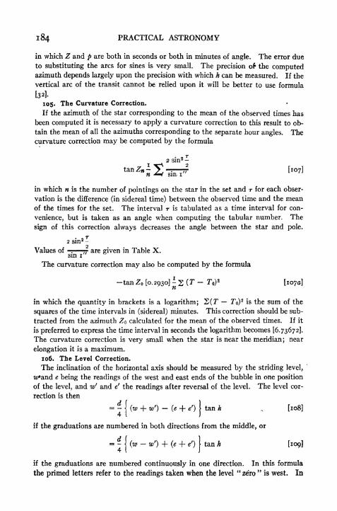
184 PRACTICAL ASTRONOMY
in which Z and p are both in seconds or both in minutes of angle. The error due
to substituting the arcs for sines is very small. The precision of the computedazimuth depends largely upon the precision with which h can be measured. If the
vertical arc of the transit cannot be relied upon it will be better to use formula
[32]-
105. The Curvature Correction.
If the azimuth of the star corresponding to the mean of the observed times has
been computed it is necessary to apply a curvature correction to this result to ob-
tain the mean of all the azimuths corresponding to the separate hour angles. Thecurvature correction may be computed by the formula
in which n is the number of pointings on the star in the set and r for each obser-
vation is the difference (in sidereal time) between the observed time and the meanof the times for the set. The interval r is tabulated as a time interval for con-
venience, but is taken as an angle when computing the tabular number. The
sign of this correction always decreases the angle between the star and pole.
. r2 sin2 -
Values of -: 77 are given in Table X.sin i
'
The curvature correction may also be computed by the formula
-tan Z [0.2930] S (T - To)2
[1070]
in which the quantity in brackets is a logarithm; 2(T To)2 is the sum of the
squares of the time intervals in (sidereal) minutes. This correction should be sub-
tracted from the azimuth Z calculated for the mean of the observed times. If it
is preferred to express the time interval in seconds the logarithm becomes [6.73672].
The curvature correction is very small when the star is near the meridian; near
elongation it is a maximum.
106. The Level Correction.
The inclination of the horizontal axis should be measured by the striding level,
wand e being the readings of the west and east ends of the bubble in one position
of the level, and w' and e' the readings after reversal of the level. The level cor-
rection is then
= -| (w + w'}
-(e + e'} \
tan h , [108]4 I J
if the graduations are numbered in both directions from the middle, or
= -( (w - w') + (e + e'} \
tan h [109]4 I J
if the graduations are numbered continuously in one direction. In this formula
the primed letters refer to the readings taken when the level"zero
"is west. In

OBSERVATIONS FOR AZIMUTH 185
both formulae d is the angular value of a level division and h is the altitude of the
star.
If the azimuth mark is not in the horizon a similar correction must be applied
to the readings on the mark. Ordinarily this correction is negligible.
When applying this correction it should be observed that when the west end of
the axis is too high the instrument has to be turned too far west (left) when pointing
at the star. The correction must therefore be added to the measured angle if the
mark is west of the star; in other words the reading on a circle numbered clockwise
must be increased. If the correction is applied to the computed azimuth of the
mark the sign must be reversed.
107. Diurnal Aberration.
If a precise azimuth is required a correction should be applied for the effect of
diurnal aberration, or the apparent displacement of the star due to the earth's
rotation. The observer is being carried directly toward the east point of the hori-
zon with a velocity depending upon his latitude. The displacement will therefore
be in a plane through the observer, the east point, and the star. The amount of
the correction is given by
o".32 cos <f> cos Zn sec h [no]
The product of cos < and sec h is always nearly unity for a close circumpolar and
cos Z is also nearly unity. The correction therefore varies but little from ".32.
Since the star is displaced toward the east the correction to the star's azimuth is
positive.
1 08. Observations and Computations.
In the examples which follow, the first illustrates a method appropriate for
small surveyor's transits. The time is determined by the altitude of a star near
the prime vertical and the azimuth of Polaris is computed by formula [106]. Cor-
rections for curvature, inclination and aberration are omitted.
In the second example the time was determined somewhat more precisely and a
larger number of repetitions was used. The instrument was an 8-inch repeater
reading to 10".
The third and fourth examples are taken from the U. S. Coast and Geodetic
Survey Spec. Publ. No. 14, and illustrates the methods used by that Survey where
the most precise results are required for geodetic purposes.
Example i
Observed altitudes of Regulus (east), Feb. n, 1908, in lat. 42 21'.
Altitude Watch
17 05' 7^ 12"* 1 6s
17 3i 14 3i
17 49 16 0718 02 17 20
The right ascension of Regulus is io&o3TO29*. i; the declination is 4-12 24' 57".
From these data the sidereal time corresponding to the mean watch reading (7*15^
03^.5) is found to be 4* 53 423.7.
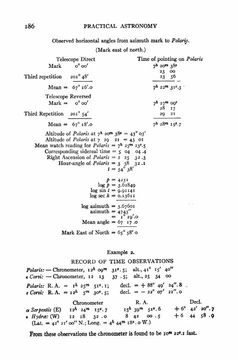
186 PRACTICAL ASTRONOMY
Observed horizontal angles from azimuth mark to Polaris.
(Mark east of north.)
Telescope Direct Time of pointing on Polaris
Mark o oo' 7 20 38*
23 ooThird repetition 201 48' 23 56
Mean = 67 i6/.o ?
h 22 31*.3
Telescope Reversed
Mark = o oo' 7* 27 09*28 17
Third Repetition 201 54' 29 21
Mean = 67 iS'.o 7* 28"*
Altitude of Polaris at 7* 2O 38* = 43 03'
Altitude of Polaris at 7 29 21 = 43 01
Mean watch reading for Polaris 7h
25 23^.5
Corresponding sidereal time = 5 04 04 .4
Right Ascension of Polaris = i 25 32 .3
Hour-angle of Polaris = 3 38 32 .1
t = 54 38'
P = 4251log/> = 3-62849
log sin / = 9.91141
log sec h 0.13611
log azimuth = 3.67601azimuth = 4743"
= i i9'.oMean angle = 67 17 .o
Mark East of North = 65 58' o
Example 2.
RECORD OF TIME OBSERVATIONS
Polaris: Chronometer, i2h 09 31^.5; alt., 41 15' 4"c Com: Chronometer, 12 13 37 . 5; alt, 25 34 oo
Polaris: R.A. = i* 25 si.i; decl. = +88 49' 24"-8 ,
eCorvi: R.A. = 12* 5"* 30* -5J ded. = - 22 07' 21". o
Chronometer R. A. Decl.
a Serpentis (E) 12* 24 153.7 15* 39W Si8
- 6 +6 42' 20".;
* Hydra: (W) 12 18 32 .o 8 42 00.5 + 6 44 5 -9
(Lat. = 42 21' oo" N.; Long. & 44*1 X8 . o W.)
From these observations the chronometer is found to be io* 22*.! fast.
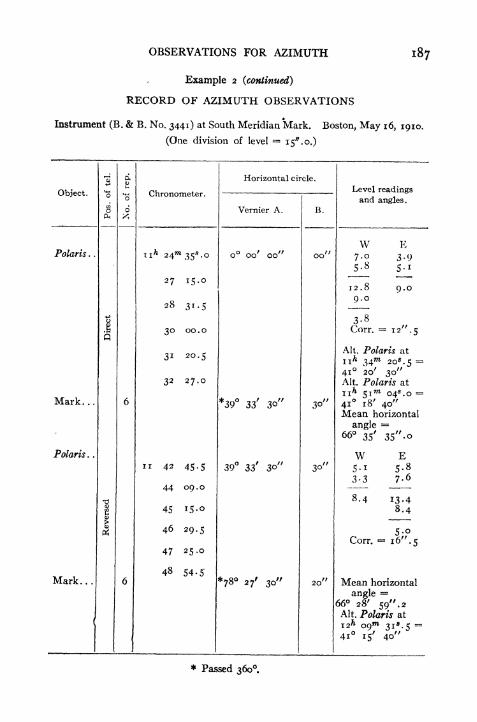
OBSERVATIONS FOR AZIMUTH I87
Example 2 (continued)
RECORD OF AZIMUTH OBSERVATIONS
Instrument (B. & B. No. 3441) at South Meridian Mark. Boston, May 16, 1910.
(One division of level ==i5
//
.o.)
* Passed 360.

l88 PRACTICAL ASTRONOMY
Example 2 (continued)
COMPUTATION OF AZIMUTHMean of Observed times = n* 37"* 25*. 6
Chronometer correction = 10 22.1
Sidereal time = n 27 03 .5
R. A. of Polaris = i 25 51 .1
Hour Angle of Polaris =1001 12. 4
t =150 18' 06"
log cos < = 9.868670
log tan 5 = 1.687490
log cos <f> tan 5 = 1.556160
cos tan 8 = 35.9882
log sin </>= 9.82844
log cos t = 9.93884
log sin cos t = 9.76728
sin cos / = .5852
denominator =36.5734
log sin t = 9.694985
log denom. = 1.563165
log tan Z = 8. 131820Z o 46' 34^2
Curvature correction = 2. i
Azimuth of star o 46 32.1
Measured angle, first half = 66 35' 35". o
Level correction = 12.5Corrected angle = 66 35 22.5
Measured angle, second half = 66 28 59 . 2
Level correction = +16 .5
Corrected angle = 66 29 15.7
Mark east of star = 66 32 19 . T
Mark east of North = 65 45' 47", o
109. Meridian by Polaris at Culmination.
The following method is given in Lalande's Astronomy andwas practiced by Andrew Ellicott, in 1785, on the Ohio and
Pennsylvania boundary survey. The direction of the meridian
is determined by noting the instant when Polaris and some

OBSERVATIONS FOR AZIMUTH 189
Example 3
RECORD AZIMUTH BY REPETITIONS.[Station, Kahatchee A. State, Alabama. Date, June 6, 1898. Observer,
O. B. F. Instrument, lo-inch Gambey No. 63. Star, Polaris.]
[One division striding level = 2. "67.]

PRACTICAL ASTRONOMY
COMPUTATION AZIMUTH BY REPETITIONS[Kahatchee, Ala. = 33 13' 4o".33-]
To the mean result from the above computation must be applied corrections for diurnal aberra-tion and eccentricity (if any) of Mark. Carry times and angles to tenths of seconds only.* Minus if west of north.

OBSERVATIONS FOR AZIMUTH 191
Example 4
HORIZONTAL DIRECTIONS
[Station, Sears, Tex. (Triangulation Station). Observer, W. Bowie. In-
strument, Theodolite 168. Date, Dec. 22, 1908.]
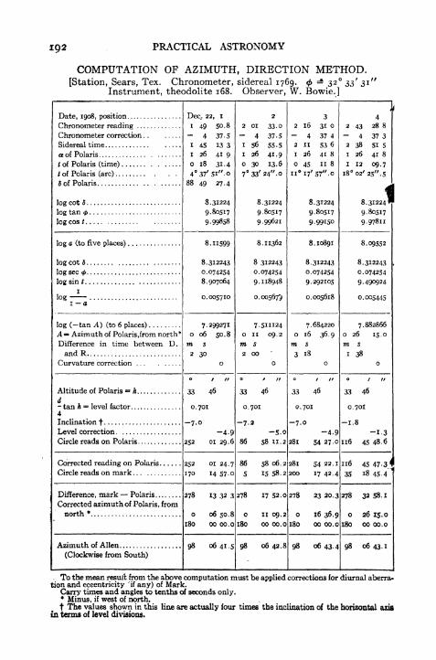
192 PRACTICAL ASTRONOMY
COMPUTATION OF AZIMUTH, DIRECTION METHOD.[Station, Sears, Tex. Chronometer, sidereal 1769. - 32 33' 31'
Instrument, theodolite 168. Observer, W. Bowie.]
. To the mean result from the above computation must be applied corrections for diurnal aberra-tion and eccentricity 'if any) of Mark.
Carry times and angles to tenths of seconds only.* Minus, if west of north.
t The values shown in this line are actually lour times the inclination of the horizontal axisin terms of level divisions.

OBSERVATIONS FOR AZIMUTH *93
other star are in the same vertical plane, and then waiting a
certain interval of time, depending upon the date and the star
^served, when Polaris will be in the meridian. At this instant
Polaris is sighted and its direction then marked on the ground
by means of stakes. The stars selected for this observation
should be near the hour circle through the polestar; that is,
their right ascensions should be nearly equal to that
of the polestar, or else nearly i2hgreater. The stars
best adapted for this purpose at the present time are
d Cassiopeia and f Ursa Majoris.
The interval of time between the instant when
the star is vertically above or beneath Polaris and
the instant when the latter is in the meridian is
computed as follows : In Fig. 73 P is the pole, P' is
Polaris, S is the other star (6 Cassiopeia) and Z is
the zenith. At the time when S is vertically under
P', ZP'S is a vertical circle. The angle desired is
ZPP', the hour angle of Polaris. PP' and PS, the
polar distances of the stars, are known quantities;
P'PS is the difference in right ascension, and maybe obtained from the Ephemeris. The triangle P'PS
may therefore be solved for the angle at P'. Sub-a
tracting this from 180 gives the angle ZP'P\ PP'IG ' 7
is known, and PZ is the colatitude of the observer.
The triangle ZPfP may then be solved for ZPP', the desired
togle. Subtracting ZPPffrom 180 or i2
hgives the sidereal
interval of time which must elapse between the two
observations. The angle SPPr and the side PP' are so
small that the usual formulae may be simplified, by replacing
sines by arcs, without appreciably diminishing the accuracy
of the result. A similar solution may be made for the upper
culmination of & Cassiopeia or for the two positions of the
star f Ursa Majoris, which is on the opposite side of the
pole from Polaris. The above solution, using the right ascen-
sions and declinations for the date, gives the exact interval

I94 PRACTICAL ASTRONOMY
required; but for many purposes it is sufficient to use a time
interval calculated from the mean places of the stars and for a
mean latitude of the United States. The time ititerval for the
star 6 Cassiopeia for the year 1910 is 6m.i and for 1920 it is about
i2m.3. For the star f Ursa Majoris the time interval for the
year 1910 is approximately 6^.7, while for 1920 it is 11^.3. Be-
ginning with the issue for 1910 the American Ephemeris and
Nautical Almanac gives values of these intervals, at the end
of the volume, for different latitudes and for different dates.
Within the limits of the United States it will generally be nec-
essary to observe on b Cassiopeia when Polaris is at lower
culmination and on f Ursce Majoris when Polaris is at upperculmination.
The determination of the instant when the two stars are in
the same vertical plane is necessarily approximate, since there is
some delay in changing the telescope from one star to the other.
The motion of Polaris is so slow, however, that a very fair
degree of accuracy may be obtained by first sighting on Polaris,
then pointing the telescope to the altitude of the other star (say
8 Cassiopeia) and waiting until it appears in the field; when
d Cassiopeia is seen, sight again at Polaris to allow for its
motion since the first pointing, turn the telescope again to
8 Cassiopeia and observe the instant when it crosses the verti-
cal hair. The motion of the polestar during this short interval
may safely be neglected. The tabular interval of time corrected
to date must be added to the watch reading. When this com-
puted time arrives, the cross hair is to be set accurately on
Polaris and then the telescope lowered in this vertical plane and
a mark set in line with the cross hairs. The change in the
azimuth of Polaris in im of time is not far from half a minute
of angle, so that an error of a few seconds in the time of sighting
at Polaris has but little effect upon the result. It is evident that
the actual error of the watch on local time has no effect what-
ever upon the result, because the only requirement is that the
interval should be correctlv measured.
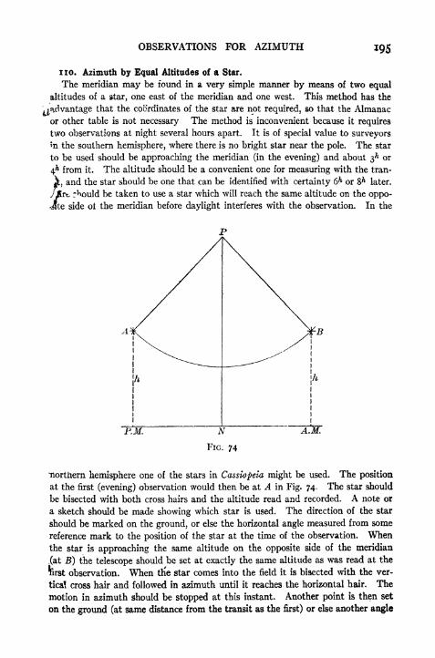
OBSERVATIONS FOR AZIMUTH 195
no. Azimuth by Equal Altitudes of a Star.
The meridian may be found in a very simple manner by means of two equal
altitudes of a star, one east of the meridian and one west. This method has the
^advantage that the coordinates of the star are not required, so that the Almanac
or other table is not necessary The method is inconvenient because it requires
two observations at night several hours apart. It is of special value to surveyors
*'n the southern hemisphere, where there is no bright star near the pole. The star
to be used should be approaching the meridian (in the evening) and about 3^ or
4^ from it. The altitude should be a convenient one for measuring with the tran-
,and the star should be one that can be identified with certainty 6^ or & later.
* r^ould be taken to use a star which will reach the same altitude on the oppo-
Jte side ot the meridian before daylight interferes with the observation. In the
-RM.
northern hemisphere one of the stars in Cassiopeia might be used. The position
at the first (evening) observation would then be at A in Fig. 74 . The star should
be bisected with both cross hairs and the altitude read and recorded. A note or
a sketch should be made showing which star is used. The direction of the star
should be marked on the ground, or else the horizontal angle measured from some
reference mark to the position of the star at the time of the observation. Whenthe star is approaching the same altitude on the opposite side of the meridian
,(at B) the telescope should be set at exactly the same altitude as was read at the
ferst observation. When trie star comes into the field it is bisected with the ver-
tical cross hair and followed in azimuth until it reaches the horizontal hair. The
motion in azimuth should be stopped at this instant. Another point is then set
on the ground (at same distance from the transit as the first) or else another angle
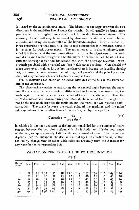
IQ4
196
PRACTICAL ASTRONOMVPRACTICAL ASTRONOMY
is turned to the same reference mark. The bisector of the angle between the two
directions is the meridian line through the transit. It will usually be found more
practicable to turn angles from a fixed mark to the star than to set stakes. The
accuracy of the result may be increased by observing the star at several different
altitudes and using the mean value of the horizontal angles. In this method tit
index correction (or that part of it due to non-adjustment) is eliminated, since it
is the same for both observations. The refraction error is also eliminated, pro-
vided it is the same at the two observations. Error in the adjustment of the hori-
zontal axis and the line of sight will be eliminated if the first half of the set is taken
with the telescope direct and the second half with the telescope reversed. With
a transit provided with a vertical arc (180) this cannot be done. Care should bej
taken to re-level the plates just before the observation is begun; the levelling should)*
not, of course, be done between the pointing on the mark and the pointing on the
star, but may be done whenever the lower clamp is loose.
in. Observation for Meridian by Equal Altitudes of the Sun in the Forenoon
and in the Afternoon.
This observation consists in measuring the horizontal angle between the mark
and the sun when it has a certain altitude in the forenoon and measuring the
angle again to the sun when it has an equal altitude in the afternoon. Since the
sun's declination will change during the interval, the mean of the two angles will
not be the true angle between the meridian and the mark, but will require a small
correction. The angle between the south point of the meridian and the point"
midway between the two directions of the sun is given by the equation
Correction =cos
<f>sin t
in which d is the hourly change in declination multiplied by the number of hours
elapsed between the two observations, < is the latitude, and / is the hour angle
of the sun, or approximately half the elapsed interval of time. The correction
depends upon the change in the declination, not upon its absolute value, so that
the hourly change may be taken with sufficient accuracy from the Almanac for
any year for the corresponding date.
VARIATION PER HOUR IN SUN'S DECLINATION
(1925)

OBSERVATIONS FOR AZIMUTH 197
In making the observation the instrument is set up at one end of the line whose
azimuth is to be determined, and the plate vernier set at o. The vertical cross
hair is set on the mark and the lower clamp tightened. The sun glass is then put
iri position, the upper clamp loosened, and the telescope pointed at the sun. It
P, not necessary to observe on both edges of the sun, but is sufficient to sight,
say, the lower limb at both observations, and to sight the vertical cross hair on
the opposite limb in the afternoon from that used in the forenoon. The hori-
zontal hair is therefore set on the lower limb and the vertical cross hair on the left
limb. When the instrument is in this position the time should be noted as accu-
rately as possible. The altitude and the horizontal angle are both read. In the
afternoon the instrument is set up at the same point, and the same observation is
made, except that the vertical hair is now sighted on the right limb; the horizontal
hair is set on the lower limb as before. A few minutes before the sun reaches an
altitude equal to that observed in the morning the vertical arc is set to read exactly
the same altitude as was read at the first observation. As the sun's altitude de-
creases the vertical hair is kept tangent to the right limb until the lower edge
of the sun is in contact with the horizontal hair. At this instant the time is again
noted accurately; the horizontal angle is then read. The mean of the two circle
readings, corrected for the effect of change in declination, is the angle from the
mark to the south point of the horizon. The algebraic sign of the correction is
determined from the fact that if the un is going north the mean of the two ver^
nier readings lies to the west of the south point, and vice versa. The precision
of the result may be increased by taking several forenoon observations in suc-
cession and corresponding observations in the afternoon.
Example.
Lat. 42 18' N. Apr. 19, 1906.
A.M. Observations. P.M. Observations.
Reading on Mark, o oo' oo" Reading on Mark, o oo' oo"
Alt., 24 58' f Alt., 24 58'U&L limbs Hor. Angle, 357 14' 15" U & R limbs Hor. Angle, 162 28' oo"
Time, 7^ igm 30* [ Time, 4** i2 15*
\ elapsed time = 4h 26- 22**
t = 66 35' 30" Incr. in decl. = + 52" X 4^.44'
log sin/ = 9.96270 = -f 230^.9
log cos = 9.86902
9.83172 Mean Circle Reading =79 51' 08"
log 230^.9 = 2.36342 Correction = 5 40
2.53170 True Angle S 79 45' 28" E.Corr. = 340". 2 Azimuth ~ 280 14' 32"
112. Azimuth of Sun near Noon.
The azimuth of the sun near noon may be determined by means of Equa. [30],
provided the local apparent time is known or can be computed. If the longitude
and the watch correction on Standard Time are known within one or two seconds
the local apparent time may be readily calculated. This method may be useful
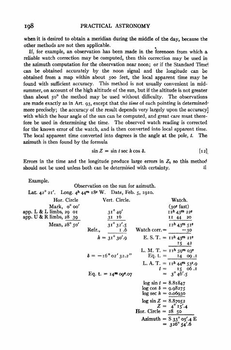
198 PRACTICAL ASTRONOMY
when it is desired to obtain a meridian during the middle of the day, because the
other methods are not then applicable.
If, for example, an observation has been made in the forenoon from which a
reliable watch correction may be computed, then this correction may be used in
the azimuth computation for the observation near noon; or if the Standard Timel
can be obtained accurately by the noon signal and the longitude can be
obtained from a map within about 500 feet, the local apparent time may be
found with sufficient accuracy. This method is not usually convenient in mid-
summer, on account of the high altitude of the sun, but if the altitude is not greater
than about 50 the method may be used without difficulty. The observations
are made exactly as in Art. 93, except that the time of each pointing is determined'
more precisely; the accuracy of the result depends very largely upon the accuracy]with which the hour angle of the sun can be computed, and great care must there-
fore be used in determining the time. The observed watch reading is corrected
for the known error of the watch, and is then converted into local apparent time.
The local apparent time converted into degrees is the angle at the pole, t. The
azimuth is then found by the formula
sin Z = sin / sec h cos 5. [12]
Errors in the time and the longitude produce large errors in Z$ so this method
should not be used unless both can be determined with certainty. A
Example.Observation on the sun for azimuth.
Lat. 42 21'. Long. 4* 44 18* W. Date, Feb. 5, 1910.
Hor. Circle
Mark, o oo'
app. L & L limbs, 29 or
app. U & R limbs, 28 39
Mean, 28 50'
Vert. Circle.
3i 49'
31 16
Refr.,
h =1.6
Watch.
(30* fast)- -V 22*
i I 44 20
5 = -l602 /
32.2//
Eq. t.
Watch corr.
E. S. T.
L. M. T.
Eq. t.
L. A. T.
log sin t
log cos 5
log sec h
log sin ZZ
Hor. Circle
Azimuth
-30= n* 43^ 21*
15 42
= 1 1* 59 03*
14 09 .1
15 06 .1
" 346'.5
= 8.81847: 9-98275= 0.06930
8.87052s 4i5'-4: 28 50
.
326 S4'.6

OBSERVATIONS FOR AZIMUTH 199
113. Meridian by the Sun at the Instant of Noon.3"
If the error of the watch can be determined within about one second, and the
sun's decimation is such that the noon altitude is not too high for convenient ob-
serving and accurate results, the following method of determining the meridian
will often prove useful. Before beginning the observation the watch time of local
apparent noon should be computed and carefully checked. If the centre of the
sun can be sighted accurately with the vertical hair at this time the line of sight
will be in the meridian, pointing to the south if the observer is in the northern
hemisphere. As this is not usually practicable the vernier reading for the south
point of the horizon may be found as follows: Set the " A "vernier to read o,
sight on a reference mark (such as a point on the line whose bearing is to be found)
|and clamp the lower motion. Loosen the upper clamp and, about iom before noon,
set the vernier so that the vertical hair is a little in advance of the west edge of
the sun's disc. Read the watch as each limb passes the vertical hair and note the
vernier reading. Then set the vernier so that the line of sight is nearly in the
meridian and repeat the observation. It is best to make a third set as soon as
possible after the second to be used as a check.
The mean of the two watch readings in each observation is the reading for the
centre of the sun. This may be checked roughly by reading also the time when
the sun's disc appears to be bisected. From the first and second vernier readings
dad the corresponding watch times compute the motion of the sun in azimuth per
second of time. Then from the second watch reading and the watch time of ap-
parent noon, the difference of which is the interval before or after noon, computethe correction to the second vernier reading to give the reading for the meridian.
The third set of observations may be used in conjunction with the first to check the
preceding computations, by computing the second vernier reading from the ob-
served time and comparing with the actual reading. The reading for the south
point may also be computed by using the first and third or the second and third
observations.
The accuracy of the results depends upon the accuracy with which the error of
the watch may be obtained, upon the reliability of the watch, and the accuracy of
the longitude, obtained from a map or by observation. When the sun is high the
, sights are more difficult to take and the sun's motion in azimuth is rapid so that an
terror in the watch time of noon produces a larger error in the result than when it
has a low altitude at noon. The method is therefore more likely to prove satis-
factory in winter than in summer. In winter the conditions for a determination
of meridian from a morning or afternoon altitude of the sun are not favorable, so
that this method may be used as a substitute. The method is more likely to give
satisfactory results when the observer is able to obtain daily comparisons of
his watch with the time signal so that the reliability of the watch time may be
judged.
?
* The method described in this article was given by Mr. T. P. Perkins,
Engineering Dept, Boston & Maine R. R., in the Engineering News, March 31,
1904.
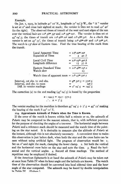
200 PRACTICAL ASTRONOMY
Example.On Jan. i, 1925, in latitude 42 22' N., longitude 71 os'.6 W., the
" A "vernier
is set at o and cross hair sighted at mark; the vernier is then set to read 42 40'
(to the right). The observed times of transit of the west and east edges of the sun
over the vertical hair are nh 36^ 39* and n* 39 ois. The vernier is then set at
45 04'.$; the times of transit are n* 460*10* and n* 48^31*. As a check the
vernier is set on 45 35', the times of transit being n>48m o8s and n ft 50^31*.
The watch is 13* slow of Eastern time. Find the true bearing of the mark from
the transit.
Local Apparent Time = 12* oo"* oo*
Equation of Time = 3 40 .8
Local Civil Time =12* 03 40^.8
Longitude difference = 15 37 .6
Eastern Standard Time nh 48 03^.2Watch slow 13
Watch time of apparent noon = n* 47 50^.2
Interval, ist obs. to 2nd obs. =gm
30^.5= 570^.5
Interval, 2nd obs. to noon = 295.7Diff. in vernier readings = 2 24^5 = 144'. 5
The correction (x) to the 2nd reading (45 04'. 5) is found by the proportion
x : 144-5 = 29.7 : 570.5
The vernier reading for the meridian is therefore 45 04^.5 + 7'.$= 45 12' making
the bearing of the mark S 45 12' E.
114. Approximate Azimuth of Polaris when the Time is Known.
If the error of the watch is known within half a minute or so, the azimuth of
Polaris may be computed to the nearest minute, that is, with sufficient precision
for the purpose of checking the angles of a traverse. The horizontal angle between
Polaris and a reference mark should be measured and the watch time of the point-
ing on the star noted. It is desirable to measure also the altitude of Polaris at
the instant, although this is not absolutely necessary. A convenient time to make^
this observation is just before dark, when both the star and the cross hairs can be
seen without using artificial light. The program of observation would be: i.
Set on o and sight the mark, clamping the lower clamp. 2. Set both the vertical
and the horizontal cross hairs on the star and note the time. 3. Read the hori-
zontal and the vertical angles. 4. Record all three readings. The method of
repetition may be employed if desired.
If the American Ephemeris is at hand the azimuth of Polaris may be taken out
at once from Table IV when its hour angle and the latitude are known. The watch
time of the observation should be converted into local sidereal time and the hour
angle of the star computed. The azimuth may be found by double interpolationin TnKlA TV nTnliAm ^\
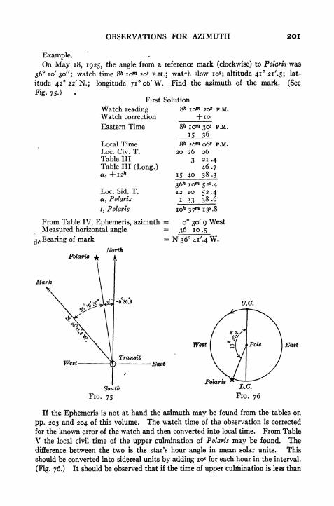
OBSERVATIONS FOR AZIMUTH 2OI
Example.On May 18, 1925, the angle from a reference mark (clockwise) to Polaris was
36 10' 30"; watch time &h 10"* 20* P.M.; wat^h slow 10s;altitude 41 21'.5; lat-
itude 42'
Fig. 75-)
22'N.; longitude 7io6'W. Find the azimuth of the mark. (See
First Solution
Watch reading 8> iow 20* P.M.
Watch correction
Eastern Time
Local TimeLoc. Civ. T.Table III
Table III (Long.)
+ 10
iom 30* P.M.
15 36
Loc. Sid. T.
a, Polaris
t, Polaris
From Table IV, Ephemeris, azimuthMeasured horizontal angle
^ Bearing of mark
NorthPolaris
Mark
8h 26 06* P.M.
20 26 06
3 21 .4
46.715 40 38.3
36^ iom 525.412 10 52 .4
i 33 38.6
o 3o'.9 West36 10.5
West
West East
South
FIG. 75
East
Polaris
If the Ephemeris is not at hand the azimuth may be found from the tables on
pp. 203 and 204 of this volume. The watch time of the observation is corrected
for the known error of the watch and then converted into local time. From Table
V the local civil time of the upper culmination of Polaris may be found. The
difference between the two is the star's hour angle in mean solar units. This
should be converted into sidereal units by adding 10s for each hour in the interval.
(Fig. 76.) It should be observed that if the time of upper culmination is less than

202 PRACTICAL ASTRONOMY
the observed time the difference is the hour angle measured toward the west, and
the star is therefore west of the meridian if this hour angle, is less than 12*. If
the time of upper culmination is greater than the observed time the difference
is the hour angle measured toward the east (or 24^ the true hour angle) and the
star is therefore east of the meridian if this angle is less than 12^.
To obtain the azimuth from Tables F and G we use the formula
Z' =p' sin t sec h. 106]
Table F gives values of p' sin t for the years 1925, 1930, and 1935, and for every
4m (or i) of hour angle. To multiply by sec h, enter Table G with the value of
p' sin I at the top and the altitude (h) at the side. The number in the table is to be^
added to p' sint,
to obtain the azimuth Z'.
It is evident that the result might be obtained conveniently by using the time
of lower culmination when the hour angle (from U. C.) is nearer to 12** than
too*.
If the altitude of the star has not been measured it may be estimated from the
known latitude by inspecting Figs. 65 and 72 and estimating how much Polaris is
above or below the pole at the time of the observation. This correction to the
altitude may also be obtained from Table I in the Ephemeris if the hour angle of
the star is known.
As an illustration of the use of these tables we will work out the example given
on p. 201.
Second Solution
Observed time
Watch correction
Eastern time
Local time
Loc. Civ. T.
Upper culmin.
10* X i<A6
Hour angle
8 low 20* P.M.
+10
8* iom 30* P.M.
15 36
8 26 06* P.M.
20 26 .1
Q 50 .7
i .8
10^ 37^.2
Table V, U. C., May 15, io O2.iCorr. for 3 days n .8
May 18'
9^ 50^.3Corr. for 1925 -fo .2
Corr. for long. -fo .2-Upper culmin. o& 50^.7
From Table F, p' sin / = o 23'. 2
From Table G^corr. 7 .7
Azimuth = o 3o'.pMeasured horizontal angle = 36 10 .5
Bearing of mark N. 36 41'.4 W.
Since the observation just described does not have to be made at any particular
time it is usually possible to arrange to sight Polaris during twilight when terres-
trial objects may still be seen distinctly and no illumination of the field of the
telescope is necessary. In order to find the star quickly before dark the telescope
should be focussed upon a very distant object and then elevated at an angle equal
to the star's altitude as nearly as this can be judged. It will be of assistance in

OBSERVATIONS FOR AZIMUTH 203
TABLE F
Values of p sin / for Polaris (in minutes)

204 PRACTICAL ASTRONOMY
TABLE G.- CORRECTION FOR ALTITUDE

OBSERVATIONS FOR AZIMUTH 205
finding the horizontal direction of the star if its magnetic bearing is estimated
and the telescope turned until the compass needle indicates this bearing. If
there is so much light that the star proves difficult to find it is well to move
k the telescope very slowly right and left. The star may often be seen when it
is in apparent motion, while it might remain unnoticed if the telescope were
motionless.
115. Azimuth from Horizontal Angle between Polaris and /9 "Ursa Minoris.*
In order to avoid the necessity for determining the time, which is often the chief
difficulty with the preceding methods, the azimuth of Polaris may be derived from
the measured horizontal angle between it and some other star, such as Ursa
\Minoris. If the horizontal angle between the two stars is measured and the lati-
Hude is known the azimuths of the stars may be calculated.
The observation consists in sighting at a mark with the vernier reading o,then sighting Polaris and reading the vernier, and finally sighting at /3 Ursa Minoris
and reading the vernier. The difference between the two vernier readings is the
difference in azimuth of the stars (neglecting the slight change in the azimuth of
Polaris during the interval). From an inspection of the table the correspond-
ing azimuth of Polaris may be found. This azimuth combined with the vernier
reading for Polaris is the azimuth of the mark.
The following example is taken from the publication f referred to:
FIELD RECORDSimultaneous Observations on a and /3 Ursa Minoris for Azimuth
(a. observed first)
Date: Friday, Nov. 9, 1923, P.M.
Telescope Direct
Latitude 37 57' 15" N.
* This method and the necessary tables were published by C. E. Bardsley,
Rolla, Mo., 1924.
t School of Mines and Metallurgy, University of Missouri; Technical Bulletin,
Vol. 7, No. 2.
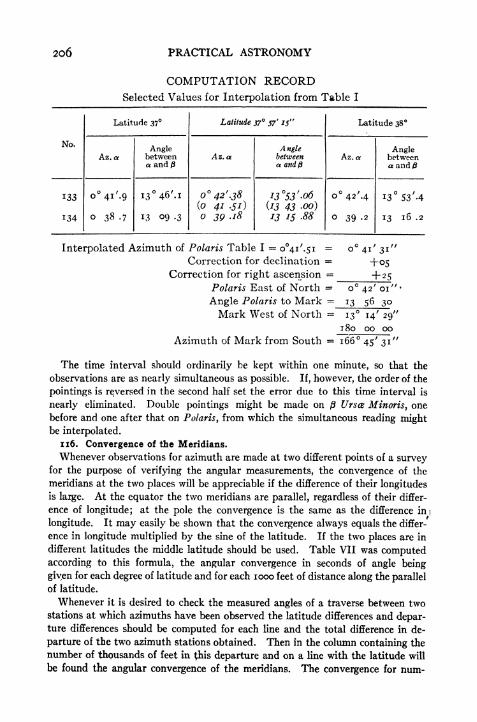
2O6 PRACTICAL ASTRONOMY
COMPUTATION RECORDSelected Values for Interpolation from Table I
Interpolated Azimuth of Polaris Table I = o4i/
.5i=
Correction for declination =Correction for right ascension =
Polaris East of North =
Angle Polaris to Mark =
Mark West of North ="
o"4i
+05+ 25
13
42 or
56 30
13
1 80
14
0029"
00
Azimuth of Mark from South = 166 45' 31"
The time interval should ordinarily be kept within one minute, so that the
observations are as nearly simultaneous as possible. If, however, the order of the
pointings is reversed in the second half set the error due to this time interval is
nearly eliminated. Double pointings might be made on /3 Ursa Minoris, one
before and one after that on Polaris, from which the simultaneous reading mightbe interpolated.
116. Convergence of the Meridians.
Whenever observations for azimuth are made at two different points of a surveyfor the purpose of verifying the angular measurements, the convergence of the
meridians at the two places will be appreciable if the difference of their longitudes
is large. At the equator the two meridians are parallel, regardless of their differ-
ence of longitude; at the pole the convergence is the same as the difference ini
longitude. It may easily be shown that the convergence always equals the differ-
ence in longitude multiplied by the sine of the latitude. If the two places are in
different latitudes the middle latitude should be used. Table VII was computedaccording to this formula, the angular convergence in seconds of angle being
giyen for each degree of latitude and for each 1000 feet of distance along the parallel
of latitude.
Whenever it is desired to check the measured angles of a traverse between twostations at which azimuths have been observed the latitude differences and depar-ture differences should be computed for each line and the total difference in de-
parture of the two azimuth stations obtained. Then in the column containing the
number of thousands of feet in (his departure and on a line with the latitude will
be found the angular convergence of the meridians. The convergence for num-
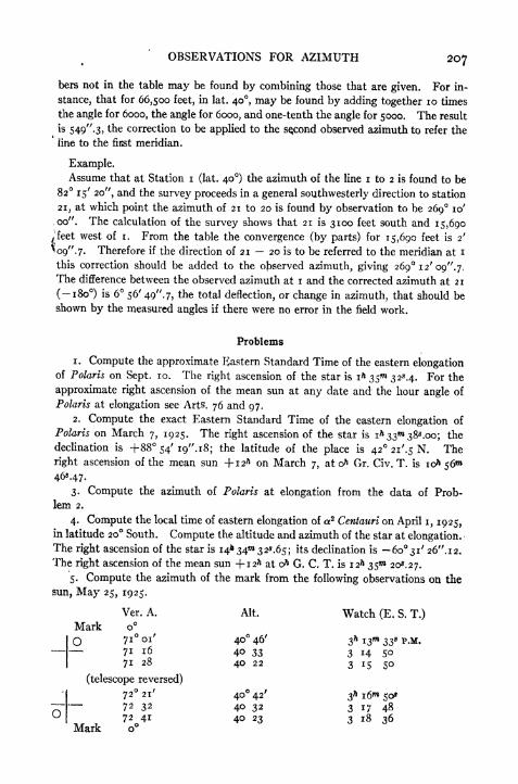
OBSERVATIONS FOR AZIMUTH 207
bers not in the table may be found by combining those that are given. For in-
stance, that for 66,500 feet, in lat. 40, may be found by adding together 10 times
the angle for 6000, the angle for 6000, and one-tenth the angle for 5000. The result
is 549".3, the correction to be applied to the second observed azimuth to refer the
line to the first meridian.
Example.Assume that at Station i (lat. 40) the azimuth of the line i to 2 is found to be
82 15' 20", and the survey proceeds in a general southwesterly direction to station
21, at which point the azimuth of 21 to 20 is found by observation to be 269 10'
,00". The calculation of the survey shows that 21 is 3100 feet south and 15,690
^feetwest of i. From the table the convergence (by parts) for 15,690 feet is 2'
^09". 7. Therefore if the direction of 21 20 is to be referred to the meridian at i
this correction should be added to the observed azimuth, giving 269 12' 09". 7.
The difference between the observed azimuth at i and the corrected azimuth at 21
(-180) is 6 56' 49". 7, the total deflection, or change in azimuth, that should be
shown by the measured angles if there were no error in the field work.
Problems
1. Compute the approximate Eastern Standard Time of the eastern elongationof Polaris on Sept. 10. The right ascension of the star is i^ 35 32*4. For the
approximate right ascension of the mean sun at any date and the hour angle of
Polaris at elongation see Arts. 76 and 97.
2. Compute the exact Eastern Standard Time of the eastern elongation of
Polaris on March 7, 1925. The right ascension of the star is i^ 33"* 38^.00; the
declination is +88 54' i9".i8; the latitude of the place is 42 2i'.5 N. The
right ascension of the mean sun +12* on March 7, at & Gr. Civ. T. is io& 56
46*47.
3. Compute the azimuth of Polaris at elongation from the data of Prob-
lem 2.
4. Compute the local time of eastern elongation of a2 Centauri on April i, 1925,in latitude 20 South. Compute the altitude and azimuth of the star at elongation.The right ascension of the star is 14* 34** 32^.65; its declination is 60 31' 26". 12.
The right ascension of the mean sun + 12^ at o& G. C. T. is 12^ 35"* 20*. 27.
5. Compute the azimuth of the mark from the following observations on the
sun, May 25, 1925.
Ver. A. Alt. Watch (E. S. T.)
Mark o
O 7i 01'
40 46' 3* i3n 33* P.M.
7i 16 40 33 3 i4 So7i 28 40 22 3 15 50
(telescope reversed)
72 21' 40 42' 3*i65o*~ 72 32 40 32 3 i7 48U
, ,72 41 40 23 3 18 36
Mark o

208 PRACTICAL ASTRONOMY
Lat. = 42 29'.s N.; long.-
71 o;'.s W. I. C. = o". Declination at G. C. T.
eft = +20 48' 55".8; varia. per hour = -f-27".6o. Equa. of time = +3m 19*48;varia. per hour = 0^.230.
6. Compute the azimuth of the mark from the following observations on the
sun, May 25, 1925.
Ver. A. Alt. Watch (E. S. T.)
Mark o
O 76 25' 35 28' 3*4237*p.M.76 39 35 13 3 43 5776 49 35 02 3 44 55
(telescope reversed)
O77 37 35 25' 3* 45m 5&77 49 35 12 3 46 55
78 oo 35 oo 3 47 58
Lat. = 42 29'.s N.; long.=
71 07'.$ W. I. C. = o'. Declination at G. C. T.
o = -j-2o48' 55". 8; varia. per hour = -f-27".6o. Equa. of time = +3 19*48;
varia. per hour =03.230.
7. On March 2, 1925, in latitude 42 01' N., longitude 71 07' W., the hori-
zontal angle is turned clockwise from a mark to the sun with the following results:
Left and lower limbs; hor. circle, 53 56'; altitude, 40 31'; watch, n^ 58"* 50*.
Right and upper limbs; hor. circle, 55 09'; altitude, 41 02'; watch i2h 00** 20s.
Watch is 3* fast of E. S. T. The declination of the sun at o& G. C. T. = -7 28'
4o".8; varia. per hour, +57^.06. Equa. of time, 12"* 28*45; varia. per hour
4-0*496. Compute the azimuth of the mark.
8. On March 2, 1925 vernier A is set at o and telescope pointed at a mark.
Vernier A is then set to read (clockwise) 50 01'; west edge of sun passed at n*
44 43* and east edge at 11^46 53*, by watch. Vernier is next set at 53 18';
west edge of sun passed at nh S4m 44* and east edge at nh56 55*. Watch is 3*
fast of Eastern Standard Time. The latitude is 42 01' N., longitude is 71 07'
west. The equation of time at o7* G. C. T, March 2, 1925 is i2m 28*45; varia.
per hour, +0*496. Compute the azimuth of the mark.
9. The transit is at sta. B; vernier reads o when sighting on sta. A. At
8& oom P.M. (E. S. T.) Polaris is sighted; alt. = 41 25'. Horizontal angle 113 30'*
(clockwise) to star. Date, May 8, 1926. Compute the bearing of B. A.
10. Prove tnat the horizontal angle between the centre of the sun and the right
or left limb is s sec k where s is the apparent angular semidiameter and h is the
apparent altitude.
11. Prove that the level correction (Art. 106, p. 184) is i tan h where i is the
inclination as given by the level.
12. Why could not Equa. [106], p. 183, be used in place of Equa. [31], p. 36,
in the method of Art. 112?
13. If there is an error of 4* in the assumed value of the watch correction and
an azimuth is determined by the method of Art. 112, (near noon) what would be the
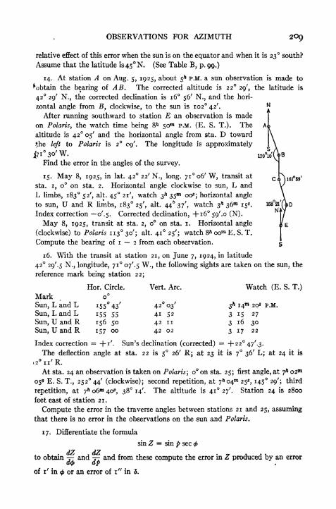
OBSERVATIONS FOR AZIMUTH
relative effect of this error when the sun is on the equator and when it is 23 south?
Assume that the latitude is45N. (See Table B, p. 99.)
14. At station A on Aug. 5, 1925, about 5* P.M. a sun observation is made to
^obtain the bearing of AB. The corrected altitude is 22 29', the latitude is
42 29' N., the corrected declination is 16 56' N., and the hori-
zontal angle from J5, clockwise, to the sun is 102 42'.
After running southward to station E an observation is made
on Polaris, the watch time being 8>* 50"* P.M. (E. S. T.). The
altitude is 42 05' and the horizontal angle from sta. D toward
,the left to Polaris is 2 09'. The longitude is approximately
Kso'w.Find the error in the angles of the survey.
15. May 8, 1925, in lat. 42 22' N., long. 71 06' W, transit at
sta. i, o on sta. 2. Horizontal angle clockwise to sun, L and
L limbs, 183 52', alt. 45 21', watch 3* 35 oo5;horizontal angle
to sun, U and R limbs, 183 25', alt. 44637', watch 3^ 36^ 15*.
Index correction 0^.5. Corrected declination, +16 59^.0 (N).
May 8, 1925, transit at sta. 2, o on sta. i. Horizontal angle
(clockwise) to Polaris 113 30'; alt. 41 25'; watch 8> oo E. S. T.
Compute the bearing of i 2 from each observation.
16. With the transit at station 21, on June 7, 1924, in latitude
42 29^.5 N., longitude, 71 07'. 5 W., the following sights are taken on the sun, the
reference mark being station 22;
Vert. Arc.
42 03'
41 52
42 ii
42 02
Watch (E. S. T.)
3^ I4m 20s P.M.
3 15 27
3 16 30
3 17 22
Index correction -f-i'. Sun's declination (corrected)= +2247 /
>3.
The deflection angle at sta. 22 is 5 26' Rj at 23 it is 7 36' L; at 24 it is
t2n'R.At sta. 24 an observation is taken on Polaris', o on sta. 25; first angle, at 7^ 02^
05* E. S. T., 252 44' (clockwise); second repetition, at 7^04^ 25*, 145 29'; third
repetition, at 7" o6* 40*, 38 14'. The altitude is 41 27'. Station 24 is 2800
feet east of station 21.
Compute the error in the traverse angles between stations 21 and 25, assuming
that there is no error in the observations on the sun and Polaris.
17. Differentiate the formula
sin Z = sin p sec </>
it7 f!7to obtain -r- and 3- and from these compute the error hi Z produced by an error
a<f> dp ,
of i' in or an error of i" in 5.

210 PRACTICAL ASTRONOMY
18. Observation on sun Oct. 21, 1925, for azimuth.
Watch (E. S. T.)
7* I0* 30* A.M.
7 II 22'
7 12 30
7 13 32
Index correction to altitude = + *'
Decimation at o*, G. C. T., Oct. 21 = 10 26' 02^.5 ; varia. per hour =
53"-78. Latitude = 42 29'.$; longitude = 71 07^.5 W. Equa. of time a
o -fi5* ii*.2i; varia. per hour, +.417. Compute the azimuth of the marl

CHAPTER XIV
NAUTICAL ASTRONOMY
117. Observations at Sea.
The problems of determining a ship's position at sea and the
bearing of a celestial object at any time are based upon exactly
the same principles as the surveyor's problems of determininghis position on land and the azimuth of a line of a survey. Themethod of making the observations, however, is different,
since the use of instruments requiring a stable support, such as
the transit and the artificial horizon, is not practicable at sea.
The sextant does not require a stable support and is well adaptedto making observations at sea. Since the sextant can be used
only to measure the angle between two visible points, it is
necessary to measure all altitudes from the sea-horizon and to
make the proper correction for dip.
Determination of Latitude at Sea
118. Latitude by Noon Altitude of Sun.
The determination of latitude by measuring the maximumaltitude of the sun's lower limb at noon is made in exactly the
same way as described in Art. 70. The observation should be
begun a little before local apparent noon and altitudes measured
in quick succession until the maximum is reached. In measur-
ing an altitude above the sea-horizon the observer should bring
the sun's image down until the lower limb appears to be in
contact with the horizon line. The sextant should then be
tipped by rotating right and left about the axis of the telescope
so as to make the sun's image describe an arc; if the lower limb
of the sun drops below the horizon at any point, the measured
altitude is too great, and the index arm should be moved until
the sun's image is just tangent to the horizon when at the lowest

212 PRACTICAL ASTRONOMY
point of the arc. (Fig. 77.)
following example.
This method is illustrated by the
Example.
Observed altitude of sun's lower limb 69 21' 30", bearing north. Index cor-
rection = i' 10"; height of eye = 18 feet; corrected sun's decimation =
+9oo /26" (N). The approximate latitude and longitude are n3o/
S, 15 oo'
W. The corrections for dip, refraction, parallax and semidiameter may be taken
out separately; in practice the whole correction is taken from Bowditch, American
Practical Navigation, Table 46. The latitude is computed by formula [i]. Ifi
the sun is bearing N the zenith distance is marked S, and vice versa. The zenith
distance and the declination are then added if both are N or both are S, but sub-
tracted if one is N and one is S; the latitude will have the same name (N or S) as
the greater of the two.
Observed alt.
Correction
69 21' 30"
+ 10 18
Tab. 46
I.C.
True altitude 69 31' 48"
Zenith distance 20 28 1 2 S
Declination 9 oo 26 NLatitude 11 27' 46" S
-t-ll' 28"
+ 1 10
+10' 18"
oSea
FIG. 77
Horizon
119. Latitude by Ex-Meridian Altitude.
If for any reason the altitude is not taken precisely at noon the latitude may be
found from an altitude taken near noon provided the time is known. If the in-
terval from noon is not over 25 minutes the correction may be taken from Tables
26 and 27, Bowditch. For a longer interval of time formula [300] should be used.
When using Table 26, look up the declination at the top of the page and the latitude
at the side; the tabular number (a) is the variation of the altitude in one minute
from meridian passage. To use Table 27, find this number (a) at the side and the
number of minutes (/) before or after noon at the top; the tabular number is the
required correction, at2.
Example i.
The observed altitude of the sun's lower limb Jan. i, 1925 is 26 10' 30" bearing
south; chronometer time, 15^ 3o io; chronometer 15* fast. Height of eye 18
feet; I. C. = o". The decimation is - 23 oo'.S; equa. of time is 339.3. Lat.
by dead reckoning, 40 40' N; long, by dead reckoning, 50 02' 30".
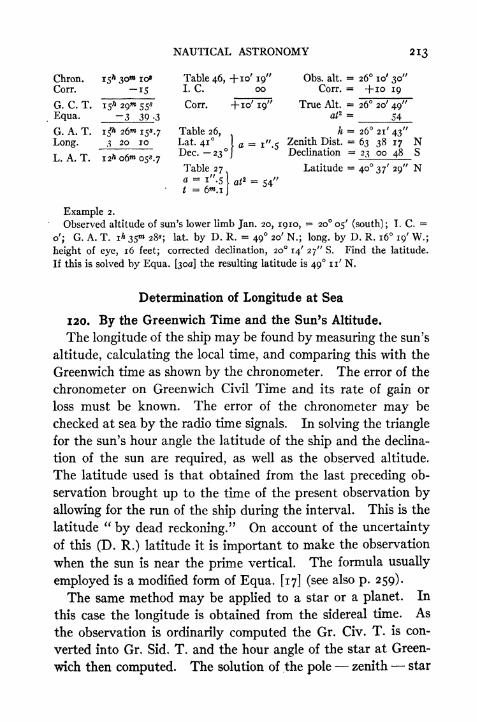
NAUTICAL ASTRONOMY 213
Chron. 15* 3o* io Table 46, H-IO' 19" Obs. alt. = 26 10' 30"Corr. 15 I. C. oo Corr. = ~}-io ig
G. C. T. 15* 29^ 55* Corr. -fio' 19" True Alt. = 26 20' 49"E(lua - ~3 39 -3 aP = 54
G. A. T. i$ 26"* i5.7 Table 26, h = 26 21' 43"Lon&- 3 20 10 Lat. 41 1 a j" 5
Zenith Dist. = 63 38 17 NL.A.T. 12^06^05^.7
Dec-- 23J'
Declination 23 oo 48 S
Table 27 ^Latitude = 40 37' 29" N
54"i"56w.!
j
Example 2.
Observed altitude of sun's lower limb Jan. 20, 1910, = 20 05' (south); T. C. =
o'; G. A. T. i* 3S 28*; lat. by D. R. = 49 20' N.; long, by D. R. 16 19' W.;
height of eye, 16 feet; corrected decimation, 20 14' 27" S. Find the latitude.
If this is solved by Equa. [300] the resulting latitude is 49 11' N.
Determination of Longitude at Sea
120. By the Greenwich Time and the Sun's Altitude.
The longitude of the ship may be found by measuring the sun's
altitude, calculating the local time, and comparing this with the
Greenwich time as shown by the chronometer. The error of the
chronometer on Greenwich Civil Time and its rate of gain or
loss must be known. The error of the chronometer may be
checked at sea by the radio time signals. In solving the triangle
for the sun's hour angle the latitude of the ship and the declina-
tion of the sun are required, as well as the observed altitude.
The latitude used is that obtained from the last preceding ob-
servation brought up to the time of the present observation by
allowing for the run of the ship during the interval. This is the
latitude"by dead reckoning." On account of the uncertainty
of this (D. R.) latitude it is important to make the observation
when the sun is near the prime vertical. The formula usually
employed is a modified form of Equa. [17] (see also p. 259).
The same method may be applied to a star or a planet. In
this case the longitude is obtained from the sidereal time. As
the observation is ordinarily computed the Gr. Civ. T. is con-
verted into Gr. Sid. T. and the hour angle of the star at Green-
wich then computed. The solution of the pole zenith star

214 PRACTICAL ASTRONOMY
triangle gives directly the hour angle of the star at the ship's
meridian. The difference between the two hour angles is the
longitude.
Example.Observed altitude of sun's lower limb on Aug. 8, 1925 (P.M.),
= 32o6/
3o//
;
chronometer 20* 37^*40*; chronometer correction, i^^o*; index correction,
-fi' oo". Height of eye 12 feet. Lat. by D. R., 44 47' N. Sun's decimation at
20s, G. C. T,, +16 07^.9; H. D., o'.7. Equa. of time at 20*, 5w
33*.i;
H. D. -hos.,3.
Chron. 20* 37^ 40* Decl. 20* -fi6o7/
.9
C - C -i 30 -0.7 X 0.6 -.4
G. C. T. 20* 36^ io Decl. + 16 o/.$Eq. 5 32.9
G. A. T. 20& 30"* 37*.! Eq. t. 20 h $m 33*.!
+0.3 X 0.6 +.2
Lat. 44 47' log sec 0.14888 Eq. t. -<Alt. 32 18 30" log esc 0.01743
pol. dist. 73 5 2 3 log cos 9.39909 Obs. alt. 3 2 06' 30"
2)iso_58__ log sin 9.83520 a 46 +"iihalf sum 75 29 log hav 1 9.40060 ^^ 32 l8
'
3O"
half sum alt. 43 10 30 t 4* oo* 48*. 7 (Bowditch, Table 45)L. A. T. 16 oo 48 .7
G. A. T. 20 30 37 .1
Long. = 4^ 29 48^.4
= 67 27^.1 W.
Determination of Azimuth at Sea
121. Azimuth of the Sun at a Given Time.
For determining the error of the compass and for other pur-
poses it is frequently necessary to know the sun's azimuth at an
observed instant of time. The azimuth may be computed by
any formula giving the value of Z when /, <f> and d are known.
In practice it is not usually necessary to calculate Z, but its
value may be taken from tables. Publication No. 71 of the U. S.
Hydrographic Office gives azimuths of the sun for every i
of latitude and of declination and every iom of hour angle. Burd-
wood's and Davis's tables may be used for the same purpose.
For finding the azimuth of a star or any object whose declination
is greater than 23 Publication No. 120 may be used.

NAUTICAL ASTRONOMY 215
Example.
As an illustration of the method of using No. 71 suppose that we require the sun's
azimuth in latitude 42 01' N, declination 22 47' S, and hour angle, or local ap-
parent time, ,9* 25** 20s A.M. Under lat. 42 N and declination 22 S, hour angle
tf* 2o> we find the azimuth N 141 40' E. The corresponding azimuth for lat.
4.3 is 141 50', that is 10' greater. The azimuth for lat. 42, decl. 23 and hour
ingle op 2ois 142 n', or 31' greater. For lat. 42, decl. 22, and hour angle 9* 30"*
the azimuth is 143 47', or 2 07' greater. The first azimuth, 141 40' must be
increased by a proportional part of each one of these variations. The desired
izimuth is therefore
141 40' + ~ X 10' + i* X 31' +^ X 127 = 143 I2'.
Go oo 10
The azimuth is N 143 12' E or S 36 48' E.
If at the time stated (gh 25 i8) the compass bearing of the sun were S 17 E,the total error of the compass would be 19 48', the north end of the compass being
west of true north. If the"variation of the compass
"per chart is 24 W, the
deviation of the compass is 24 19 48' = 4 12' E.
Determination of Position by Means of Stunner Lines
122. Stunner's Method of Determining a Ship's Position.*
If the declination of the sun and the Greenwich ApparentTime are known at any instant, these two coordinates are the
latitude and longitude respectively of a point on the earth's
surface which is vertically under the sun's centre and which
may be called the"sub-solar
"point. If an observer were at
the sub-solar point he would have the sun in his zenith. If
he were located i from this point, in any direction, the sun's
zenith distance would be i; if he were 2 away, the zenith
distance would be 2. It is evident, then, that if an observer
measures an altitude of the sun he locates himself on the cir-
cumference of a circle whose centre is the sub-solar point and
whose radius (in degrees) is the zenith distance of the sun.
This circle could be drawn on a globe by first plotting the posi-
tion of the sub-solar point by means of its coordinates, and
*This method was first described by Captain Sumner in 1843.
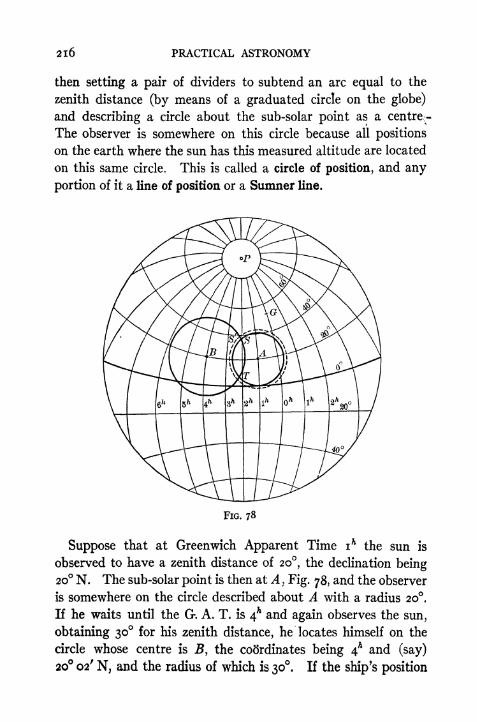
2l6 PRACTICAL ASTRONOMY
then setting a pair of dividers to subtend an arc equal to the
zenith distance (by means of a graduated circle on the globe)
and describing a circle about the sub-solar point as a ceutreT-
The observer is somewhere on this circle because all positions
on the earth where the sun has this measured altitude are located
on this same circle. This is called a circle of position, and any
portion of it a line of position or a Sumner Une.
FIG. 78
Suppose that at Greenwich Apparent Time ih
the sun is
observed to have a zenith distance of 20, the declination being20 N. The sub-solar point is then at A
, Fig. 78, and the observer
is somewhere on the circle described about A with a radius 20.
If he waits until the G*. A. T. is 4* and again observes the sun,
obtaining 30 for his zenith distance, he locates himself on the
circle whose centre is J?, the coordinates being 4A and (say)
20 02' N, and the radius of which is 30. If the ship's position

NAUTICAL ASTRONOMY 217
has not changed between the observations it is either at S or
at T, in practice there is no difficulty in deciding which is the
correct point, on account of their great distance apart. Aknowledge of the sun's bearing also shows which portion of the
circle contains the point. If, however, the ship has changed its
position since the first observation, it is necessary to allow for
its"run "
as follows. Assuming that the ship has sailed
directly away from the sun, say a distance of 60 miles or i,
then, if the first observation had been made while the ship was
in the second position, the point A would be the same, but the
radius of the circle would be 21, locating the ship on the dotted
:ircle. The true position of the ship at the second observation
is, therefore, at the intersection S'. If the vessel does not actu-
ally sail directly away from or directly toward the sun it is a
simple matter to calculate the increase or decrease in radius
due to the change in the observer's zenith.
This is in principle Sumner's method of locating a ship.
[n practice the circles would seldom have as short radii as those
in Fig. 78; small circles were chosen only for convenience in
illustrating the method. On account of the long radius of the
circle of position only a small portion of this circle can be shown
on an ordinary chart; in fact, the portion which it is necessary
to use is generally so short that the curvature is negligible and
the line of position appears on the chart as a straight line. In
order to plot a Sumner line on the chart, two latitudes may be
assumed between which the actual latitude is supposed to lie;
and from these, the known declination, the observed altitude,
and the chronometer reading, two longitudes may be computed
(Art. 120), one for each of the assumed latitudes. This gives
the coordinates of two points on the line of position by means
of which it may be plotted on the chart. Another observation
may be made a few hours later and the new line plotted in a
similar manner. In order to allow for the change in the radius
of the circle due to the ship's run between observations, it is
only necessary to move the first position line parallel to itseli
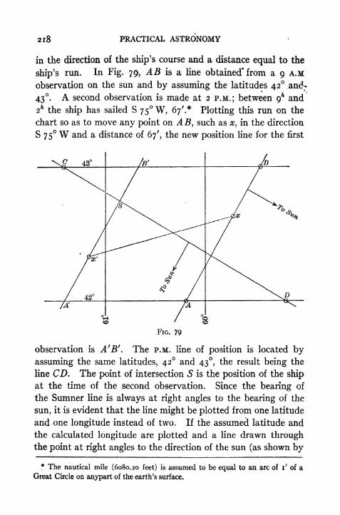
2l8 PRACTICAL ASTRONOMY
in the direction of the ship's course and a distance equal to the
ship's run. In Fig. 79, AB is a line obtained* from a 9 A.M
observation on the sun and by assuming the latitudes 42 and;
43. A second observation is made at 2 P.M.; between 9* and
2hthe ship has sailed S 75 W, 67'.* Plotting this run on the
chart so as to move any point on AB, such as x, in the direction
S 75 W and a distance of 67', the new position line for the first
FIG. 79
observation is A fB'. The P.M. line of position is located by
assuming the same latitudes, 42 and 43, the result being the
line CD. The point of intersection 5 is the position of the ship
at the time of the second observation. Since the bearing of
the Sumner line is always at right angles to the bearing of the
sun, it is evident that the line might be plotted from one latitude
and one longitude instead of two. If the assumed latitude and
the calculated longitude are plotted and a line drawn throughthe point at right angles to the direction of the sun (as shown by
* The nautical mile (6080.20 feet) is assumed to be equal to an arc of i' of a
Great Circle on anypart of the earth's surface.

NAUTICAL ASTRONOMY 2IQ
the azimuth tables) the result is the Sumner line; the ship is
somewhere on this line. The two-point method of laying down
.the line really gives a point on the chord and the one-pointrJnethod gives a point on the tangent to the circle of position.
The second method is the one usually employed for the plotting
the lines of position.
One of the great advantages of this method is that even if
one observation can be taken it may be utilized to locate
ship along a (nearly) straight line; and this is often of great
value. For example, if the first position line is found to pass
directly through some point of danger, then the navigator knows
the bearing of the point, although he does not know his distance
from it; but with the single observation he is able to avoid the
danger. In case it is a point which it is desired to reach, the
true course which the ship should steer is at once known.
123. Position by Computation.
The latitude and longitude of the point of intersection of the position lines maybe calculated more precisely than they can be taken from the chart. When the first
altitude is taken a latitude is assumed which is near to the true latitude (usually
the D. R. lat.), and a longitude is calculated. The azimuth of the sun is taken out
of the table for the same lat. and hour angle. From the run of the ship between
the first and second observations the change in lat. and change in long, are cal-
culated, usually by the traverse tables. (Tables i and 2, Bowditch). These
differences are applied as corrections to the assumed lat. and calculated long. This
places the ship on the corrected Sumner line (corresponding to A'B', Fig. 79).
When the second observation is made this corrected latitude is used in computingthe new longitude. The result of two such observations is shown in Fig. 80.
jkPoint A is the first position; A' is the position of A after correcting for the run
^'the ship; B is the position obtained from the second observation using the lati-
tude of A'. The distance A'B is therefore the discrepancy in the longitudes,
\ owing to the fact that a wrong latitude has been chosen, and is the base of a triangle
the vertex of which is C, the true position of the ship. The base angles A' and B
jLiQthe same as the azimuths of the sun at the times of the two observations. If
we drop a perpendicular from C to A'B, forming two r|ght triangles, then
Bd = OJcotZ2
A'd^CdcotZ,.>or
A/>2= A< cot Za
Api A<cotZi
where A0 is the error in latitude and Ap the difference in departure. In order to
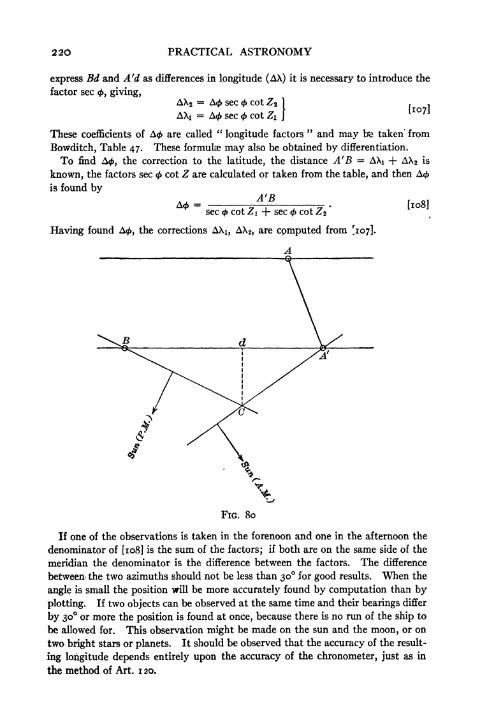
220 PRACTICAL ASTRONOMY
express Bd and A'd as differences in longitude (AX) it is necessary to introduce the
factor sec <, giving,AX2
= A< sec cot Z2 1 , ,
AXi = A< sec <#> cot Zl \U 7J
These coefficients of A0 are called"longitude factors
" and may fre taken' from
Bowditch, Table 47. These formulae may also be obtained by differentiation.
To find A<, the correction to the latitude, the distance A'B AXi + AX2 is
known, the factors sec <f> cot Z are calculated or taken from the table, and then A<
is found by
A<**=
sec <j> cot Zi -f- sec <f> cot Z2
*
\
Having found A</>, the corrections AXi, AX2,are cpmputed from [107].
FIG. 80
If one of the observations is taken in the forenoon and one in the afternoon the
denominator of [108] is the sum of the factors; if both are on the same side of the
meridian the denominator is the difference between the factors. The difference
between- the two azimuths should not be less than 30 for good results. When the
angle is small the position will be more accurately found by computation than by
plotting. If two objects can be observed at the same time and their bearings differ
by 30 or more the position is found at once, because there is no run of the ship to
be allowed for. This observation might be made on the sun and the moon, or on
two bright stars or planets. It should be observed that the accuracy of the result-
ing longitude depends entirely upon the accuracy of the chronometer, just as in
the method of Art. 1 20.

NAUTICAL ASTRONOMY 221
Example.Location of Ship by Sumner's Method.
On Jan. 4, 1910 at Greenwich Civil Time 13* 1 20*33* the observed altitude of the
L is 15 53' 30"; index correction = o"; height of eye, 36 feet; lat. by D. R.
[fc oo; N.
At Gr. Civ.*T. 18* 05** 31* the observed altitude of the sun is 17 33' 30"; index
correction o"; height of eye, 36 feet. The run between the observations was N 89
W, 45 miles.
First Observation
G. C. T. 13* i2 33* Observed alt. 15 53' 30" Declination 22 47' 04"112 47' 04"
-4W Si'-a
Long. 3* 42"* 22*
- 55 35' 30" W.
Lat. 42 oo' N Long. 55 35 '.S W.run o .8 N run i oo .7 W.
Cor'd. Lat. 42 oo'.S N Cor'd. Long. s6 36'.2W.
Second Observation
G. C. T. 18* 05 31* Observed alt. 17 33' 30" Declination -22 45' 50"Equa. 4 56 .8 Table 46 +7 31 p. d. 112 45 50
G. A. T. 18* oo 355.2 true alt. 17 41' 01" Equa. t. -4 56.8
alt. i74i'.olat. 42 oo .8 sec 0.12902
p. d. 112 45 .8 esc 0.03522
2)172 27 .6
half sum 86 i3'.8 cos 8.81790remainder 6832'.8 sin 9.96882
log hav. i . 8.95096
Sun's Az. A 33 30' W t 2* 19** 07*Az. factor 2.03 L. A. T. 14 19 07
G. A. T. 18 oo 35
Long. 3* 41* 28*

222 PRACTICAL ASTRONOMY
Cor'dLong. 56 36'. 2 i9'.4 X 1.80 = 34'$,9, corr. to ist Long.2d Long. = 55 22 ig',4 X 2.03
* 39 . -^corr. to 2d Long.
Diff. i i4'.2=
74'.2
ist Long. 56 36'.2 2d L Ong., 55 22'
74'- 2 , A rr frtlafCorr. 34-9 corr. * 39 -3
;
= 19 .4. COrr. to lat. -75 ; ,rz :
1.80+2.03V ^' 56i.3 e 56 oi'.3
.
'
. Lat. = 42 2o'.2 N .
'
. Long. = 56 01^,3 W.nc
124. Method of Marcq St. Hilaire.
Instead of solving the triangle for the angle at the pole, as explained in thc ^ pre-
ceding article, we may assume a latitude and a longitude, near to the true position
and calculate the altitude of the observed body. If the assumed position does note
happen to lie on the Sumner line the computed altitude will not be the same as
the observed altitude. The difference in minutes between the two altitudes is
the distance in miles from the assumed position to the Sumner line. If the observed
altitude is the greater then the assumed point should be moved toward the sun bythe amount of the altitude difference. A line through this point perpendicular
to the sun's direction is the true position line. It is now customary to work
up all observation by this method except those taken when the sun is exactly on the
meridian or close to the prime vertical. The former may be worked up for latitude
as explained in Art. 118. The latter may be advantageously worked as a"time
sight"or
"chronometer sight
"as in Art. 120.
The formula for calculating the altitude is
Hav. zen. dist. = hav. (Lat. ~ Decl.) -f cos Lat. cos Decl. hav. (hour angle)
in which (Lat. Decl.) is the difference between Lat. and Decl. when they have
the same sign, but their sum if they have different signs. The altitude is 90
minus the zenith distance. To illustrate this method the first observation on
p. 221 will be worked out. If we assume Lat. = 42oo'N, and Long. = 56
30' W, the hour angle (t) is computed as follows:
NAUTICAL ASTRONOMY 223
From the point in lat. 42 oo' N, long. 56 30' W, draw a line in direction S 36 48' E.
On this line lay off 24.4 miles (i' of lat. i naut. mile) toward the sun. Throughthis last point draw a line in direction S 53 12' W. This is the required position
line.
125. Altitdde and Azimuth Tables Plotting Charts.
To facilitate the graphical determination of position the Hydrographic Office
publishes two sets of tables containing solutions of triangles, and a series of charts
designed especially for rapid plotting of lines of position.
The table designated as H. O. 201 gives simultaneous altitudes and azimuths of
the sun (or any body whose declination is less than 24) for each whole degree of
platitude and declination and each iow of hour angle. Since it is immaterial what
fepoint is assumed for the purpose of calculation, provided it is not too far from the
true position, interpolation for latitude and hour angle may be avoided by taking
the nearest whole degree for the latitude, and a longitude which corresponds to an
hour angle that is in the table, that is, some even io*. By interpolating for the
minutes of the declination the altitude and azimuth are readily taken from the
table. The difference between the altitude from the table (calculated h) and the
observed altitude is the altitude difference to be laid off from the assumed position,
toward the sun if the observed altitude is the greater. To work out the exampleof Art. 124 by this table we should enter with lat. = 42, hour angle 2^40"* and
decl. 23. Interpolating for the 13' difference in declination, the corresponding
altitude is 15 24'. 7 and the azimuth is N 142. i E. The longitude corresponding
to an hour angle of 2h 40 (gh 40 L. A. T.) is 3* 47 42* or 56 55^5 W. If we plot
this point (42 N, 56 55'. 5 W) and then lay off 36'.o toward the sun (N 142.1 E)we should find a position on the same Sumner line as that obtained in Art. 124.
Small variations in the azimuth will occur when the assumed position is changed.
The different portions of the Sumner line will not coincide exactly in direction be-
cause they are tangents to a circle.
The table designated as H. O. 203 gives the hour angle and the azimuth for
every whole degree of latitude, altitude, and declination. In this table the decli-
nations extend to 27. When using this table we assume an altitude which is a
whole degree but not far from the observed altitude. It is necessary to interpo-
late, as before, for the minutes of declination; this is easily done by the use of the
*utes of change per minute which are tabulated with the hour angle and the azi-
muth. In working out the preceding example by the use of H. 0. 203 we mightuse lat. 42 N, alt. 16, decl. 22 47'.! S. The resulting hour angle is 2h 34"* 50^.6
(or L. A. T. 9^ 25^ 09^.4) and the azimuth is 143.!. The longitude corresponding
to this hour angle is 55 38' W. Plotting this position (42N., 55 38' W) and
laying off o'. 7 (the difference between the observed alt. i6oo'.7 and the tabular
alt. 16) toward the sun we obtain another point on the same position line.
The charts designed for plotting these lines show each whole degree of latitude
and longitude.* The longitude degrees are 4 inches wide and the latitude degrees
* No. 3000, sheet 7, extends from 35 N to 40 N; sheet 8 extends from 40 Nt04sN; etc.

224 PRACTICAL ASTRONOMY
proportionally greater. On certain meridians and parallels are scales of minutes
for each degree. The minutes on the latitude scale serve also*as a scale of nautical
miles for laying off the altitude differences. A compass circle is provided for lay-
ing off the azimuths. A pair of dividers, a parallel ruler and a pencil are all the
instruments needed for plotting the lines.

TABLES
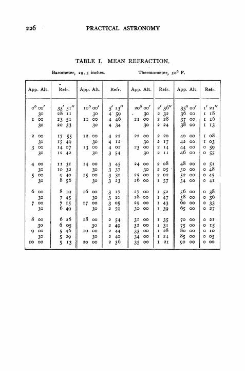
226 PRACTICAL ASTRONOMY
TABLE I. MEAN REFRACTION.
Barometer, 29.5 inches. Thermometer, 50 F.
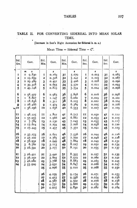
TABLES 227
TABLE II. FOR CONVERTING SIDEREAL INTO MEAN SOLAR. TIME.
*
(Increase in Sun's Right Ascension for Sidereal h. m. s.)
Mean Time == Sidereal Time C.
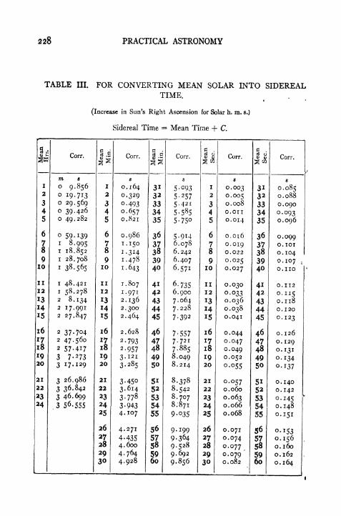
228 PRACTICAL ASTRONOMY
TABLE III. FOR CONVERTING MEAN SOLAR INTO SIDEREALTIME.
(Increase in Sun's Right Ascension for Solar h. m. s.)
Sidereal Time = Mean Time + C.

TABLES
TABLE IV.
PARALLAX SEMIDIAMETER DIP.
229

230 PRACTICAL ASTRONOMY
TABLE VLOCAL CIVIL TIME OF THE CULMINATIONS AND ELONGATIONS OF POLARIS IN
THE YEAR 1922
(Latitude, 40 N.; longitude, 90 or 6* west of Greenwich)

TABLES 231
B. To refer to any calendar day other than the first and fifteenth of each monthSUBTRACT the quantities belowfrom the tabular quantityfor the PRECEDING DATE.
C. To refer the table to Standard Time:*
(a) ADD to the tabular quantities four minutes for every degree of longi-cude the place is west of the Standard meridian and SUBTRACT when the
place is east of the Standard meridian.
(b) Times given in the table are A.M., if less than 12^; those greater than12* are P.M.
D. To refer to any other than the tabular latitude between the limits of 10 and
50 north: ADD to the time of west elongation o^.io for every degree southof 40 and SUBTRACT from the time of west elongation ow .i6 for every degreenorth of 40. Reverse these operations for correcting times' of east elon-
gation.- E. To refer to any other than the tabular longitude: ADD o"*.i6 for each 15east of the ninetieth meridian and SUBTRACT o*.i6 for each 15 west of the
ninetieth meridian.
TABLE VIFOR REDUCING TO ELONGATION OBSERVATIONS MADE NEAR ELONGATION
Sidereal time from elongation.

232 PRACTICAL ASTRONOMY
TABLE VII
CONVERGENCE IN SECONDS FOR EACH 1000 FEET ON THiPARALLEL
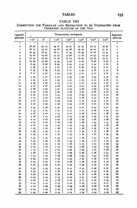
TABLES 233
TABLE VIII
CORRECTION FOR PARALLAX AND REFRACTION TO BE SUBTRACTED FROMOBSERVED ALTITUDE OF THE SUN

234 PRACTICAL ASTRONOMY
TABLE IX
LATITUDE FROM CIRCUM-MERIDIAN ALTITUDES OF THE SUN
[A = cos 5 cos<f> cosec ]

TABLES 23S
TABLE IX (Continued)
LATITUDE FROM CIRCUM-MERIDIAN ALTITUDES OF THE SUN

236 PRACTICAL ASTRONOMY
TABLE CX (Continued)
LATITUDE FROM CIRCUM-MERIDIAN ALTITUDES OF THE SUN
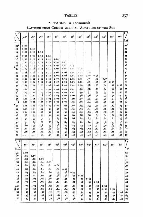
TABLES 237
^ TABLE IX (Continued)
LATITUDE FROM CIRCUM-MERIDIAN ALTITUDES OF THE SUN
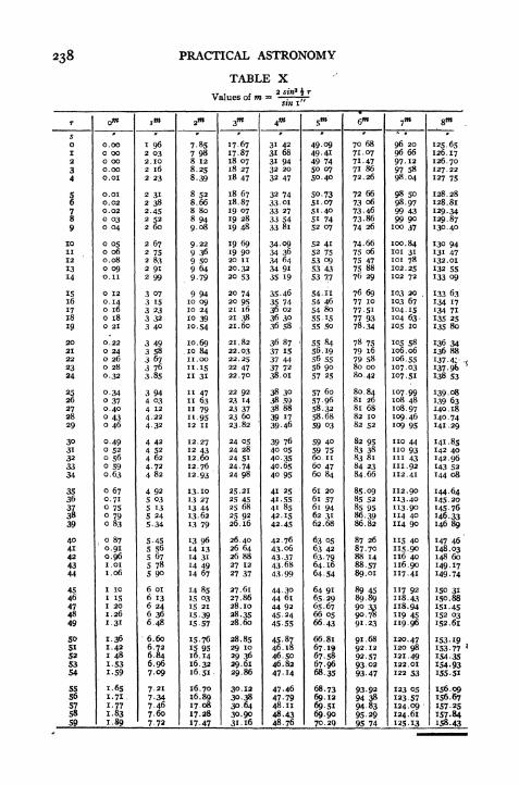
PRACTICAL ASTRONOMY
TABLE XValues of m
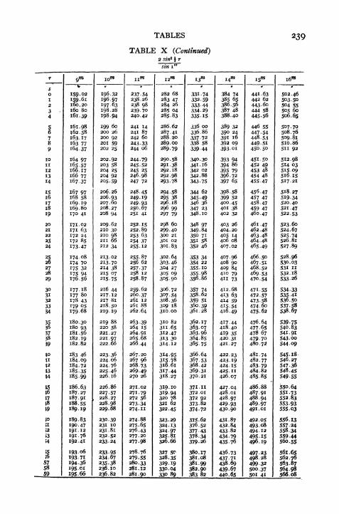
TABLES
TABLE X (Continued)
239

240 PRACTICAL ASTRONOMY
Lat.
OBSERVATION ON SUN FOR AZIMUTH*
of line from to
Long Date 192
nat sin 5
log sin <j>
log sin h
sin <t> sin h
sin 8 sin <f> sin h
log numerator
log sec <j>
log sec h
log cos Z
7
Hor. angle
Azimuth of line
logs. Decl. at o G. C. T.
corr.,
COS Zsin 8 sin $ sin h---^r-
cos ^ cos h

TABLES 241
OBSERVATION ON SUN FOR AZIMUTH
of Line from to
Alt. G. C. T.
Lat log sec .
Alt log sec .
Nat. Cos Sum
Nat. Sin Decl
Sum. log.
log vers 7jS .
Z, =
Hor. Ang. =
Azimuth to.
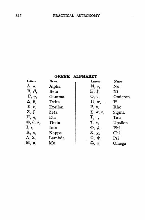
242 PRACTICAL ASTRONOMY
GREEK ALPHABETLetters.
A, a,
A,*,
5,?,
*,*,A,X,
Name.
AlphaBeta
GammaDelta
EpsilonZeta
Eta
ThetaIota
KappaLambdaMu
Letters.
2, o-, 5,
X
Name.
NuXiOmicronPi
Rho
SigmaTau
UpsilonPhi
Chi
Psi
Omega
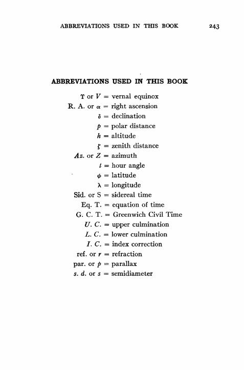
ABBREVIATIONS USED IN THIS BOOK 243
ABBREVIATIONS USED IN THIS BOOK
T or V = vernal equinox
R. A. or a = right ascension
d = declination
p = polar distance
h = altitude
f = zenith distance
Az. or Z = azimuth
/ = hour angle= latitude
X = longitude
Sid. or S = sidereal time
Eq. T. = equation of time
G. C. T. = Greenwich Civil Time
U. C. = upper culmination
L. C. = lower culmination
/. C. = index correction
ref . or r = refraction
par. or p = parallax
s. d. or s = semidiameter

APPENDIX A
THE TIDESThe Tides.
The engineer may occasionally be called upon to determine
the height of mean sea level or of mean low water as a datumfor levelling or for soundings. The exact determination of these
heights requires a long series of observations, but an approxi-
mate determination, sufficiently accurate for many purposes,
may be made by means of a few observations. In order to
make these observations in such a way as to secure the best
results the engineer should understand the general theory of
the tides.
Definitions.
The periodic rise and fall of the surface of the ocean, caused
by the moon's and the sun's attraction, is called the tide. Theword
"tide
"is sometimes applied to the horizontal movement
of the water (tidal currents), but in the following discussion
it will be used only to designate the vertical movement. Whenthe water is rising it is called flood tide; when it is falling it is
called ebb tide. The maximum height is called high water; the
minimum is called low water. The difference between the two
is called the range of tide.
Cause of the Tides.
The principal cause of the tide is the difference in the force
of attraction exerted by the moon upon different parts of the
earth. Since the force of attraction varies inversely as the
square of the distance, the portion of the earth's surface nearest
the moon is attracted with a greater force than the central
portion, and the latter is attracted more powerfully than the
portion farthest from the moon. If the earth and rnoon were
at rest the surface of the water beneath the moon would be
244
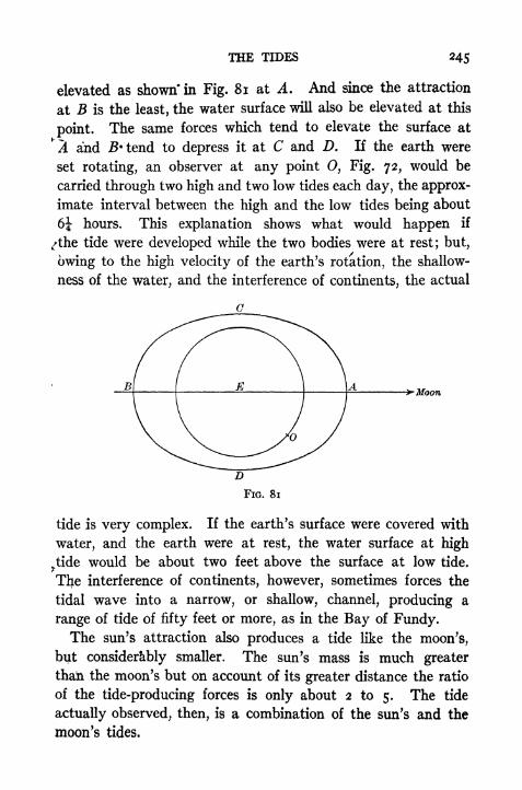
THE TIDES 245
elevated as shown* in Fig. 81 at A. And since the attraction
at B is the least, the water surface will also be elevated at this
point. The same forces which tend to elevate the surface at
*% and JB'tend to depress it at C and D. If the earth were
set rotating, an observer at any point O, Fig. 72, would be
carried through two high and two low tides each day, the approx-
imate interval between the high and the low tides being about
6J hours. This explanation shows what would happen if
,/the tide were developed while the two bodies were at rest; but,
owing to the high velocity of the earth's rotation, the shallow-
ness of the water, and the interference of continents, the actual
Moon
FlG. 81
tide is very complex. If the earth's surface were covered with
water, and the earth were at rest, the water surface at high
^tidewould be about two feet above the surface at low tide.
The interference of continents, however, sometimes forces the
tidal wave into a narrow, or shallow, channel, producing a
range of tide of fifty feet or more, as in the Bay of Fundy.The sun's attraction also produces a tide like the moon's,
but considerably smaller. The sun's mass is much greater
thaii the moon's but on account of its greater distance the ratio
of the tide-producing forces is only about 2 to 5. The tide
actually observed, then, is a combination of the sun's and the
moon's tides.

246 PRACTICAL ASTRONOMY
Effect of the Moon's Phase.
When the moon and the sun are acting along the same line, at
new or full moon, the -tides are higher than usual and are called
spring tides. When the moon is at quadrature (first orlast quai
ter), the sun's and the moon's tides partially neutralize each other
and the range of tide is less than usual; these are called neap tides.
Effect of Change in Moon's Decimation.
When the moon is on the equator the two successive high
tides are of nearly the same height. When the moon is north
FIG. 82
or south of the equator the two differ in height, as is shown in
Fig. 82. At point B under the moon it is high water, and the
depth is greater than the average. At B', where it will again
be high water about 12* later, the depth is less than the average.
This is known as the diurnal inequality. At the points E and Q,
on the equator, the two tides are equal.
Effect of the Moon's Change in Distance.
On account of the large eccentricity of the moon's orbit
the tide-raising force varies considerably during the month.
The actual distance of the moon varies about 13 per cent, and
as a result the tides are about 20 per cent greater when the moonis nearest the earth, at perigee, than they are when the moon
is farthest, at aooeee.

THE TIDES 247
Priming and L'agging of the Tides.
On the days of new and full moon the high tide at any placefollows the moon's meridian passage by a certain interval of
/time, depending upon the place, which is called the establish-
ment of the port. For a few days after new or full moon the
crest of the combined tidal wave is west of the moon's tide and
high water occurs earlier than usual. This is called the priming
of the tide. For a few days before new or full moon the crest
is east of the moon's tide and the time of high water is delayed.;This is called lagging of the tide.
All of these variations are shown in Fig. 83, which was con-
structed by plotting the predicted times and heights from the U. S.
Coast Survey Tide Tables and joining these points by straight
lines. It will be seen that at the time of new and full moon the
range of tide is greater than at the first and last quartets; at the
>oints where the moon is farthest north or south of the equator
(shown by N, S,) the diurnal inequality is quite marked,
whereas at the points where the moon is on the equator ()there is no inequality; at perigee (JP) the range is much greater
than at apogee (A).
Effect of Wind and Atmospheric Pressure.
The actual height and time of a high tide may difier consider-
ably from the normal values at any place, owing to the weather
conditions. If the barometric pressure is great the surface is
depressed, and vice versa. When the wind blows steadily into
>a bay or harbor the water is piled up and the height of the tide
is increased. The time of high water is delayed because the
water continues to flow in after the true time of high water has
passed; the maximum does not occur until the ebb and the effect
of wind are balanced.
Observatio'n of the Tides.
In order to determine the elevation of mean sea level, or,
more properly speaking, of mean half-tide, it is only necessary
to observe, by means of a graduated staff, the height of high
and low water for a number of days, the number depending upon
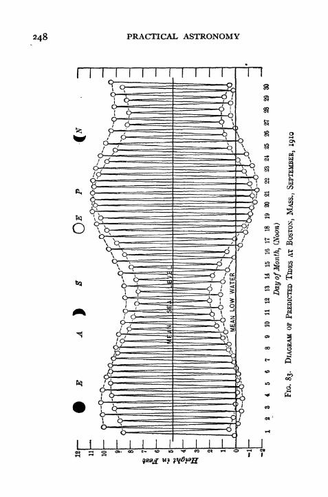
248 PRACTICAL ASTRONOMY

THE TIDES 249
the accuracy desired, and to take the mean of the gauge read-
ings. If the height of the zero point of the scale is referred to
some bench mark, by means of a line of levels, the height of the
bench macrk above mean sea level may be computed. In order
to take into account all of the small variations in the tides
it would be necessary to carry on the observations for a series
of years; a very fair approximation may be obtained, however,
in one lunar month, and a rough result, close enough for manypurposes, may be obtained in a few days.
Tide Gauges.
If an elaborate series of observations is to be made, the self-
registering tide gauge is the best one to use. This consists of
a float, which is enclosed in a vertical wooden box and which
rises and falls with the tide. A cord is attached to the float
and is connected by means of a reducing mechanism with the
;en of a recording apparatus. The record sheet is wrapped
about a cylinder, which is revolved by means of clockwork.
As the tide rises and falls the float rises and falls in the box
and the pen traces out the tide curve on a reduced scale. The
scale of heights is found by taking occasional readings on a
staff gauge which is set up near the float box and referred to a
permanent bench mark. The time scale is found by means of
reference marks made on the sheet at known times.
When only a few observations are to be made the staff gaugeis the simplest to construct and to use. It consists of a vertical
.graduated staff fastened securely in place, and at such a height
that the elevation of the water surface may be read on the
graduated scale at any time. Where the water is compara-
tively still the height may be read directly on the scale; but
where there are currents or wayes the construction must be
modified. If a current is running rapidly by the gauge but
the surface does not fluctuate rapidly, the ripple caused by the
water striking the gauge may be avoided by fastening wooden
strips on the sides so as to deflect the current at a slight
angle. The horizontal cross section of such a gauge is shown in
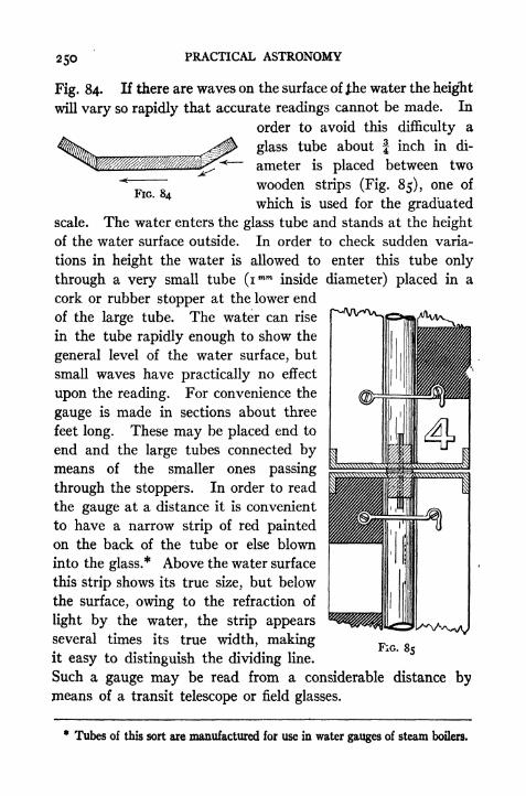
250 PRACTICAL ASTRONOMY
FIG. 84
Fig. 84. If there are waves on the surface of J;he water the height
will vary so rapidly that accurate readings cannot be made. In
order to avoid this difficulty a
glass tube about f inch in di-
ameter is placed between two
wooden strips (Fig. 85), one of
which is used for the graduatedscale. The water enters the glass tube and stands at the height
of the water surface outside. In order to check sudden varia-
tions in height the water is allowed to enter this tube only
through a very small tube (imm inside diameter) placed in a
cork or rubber stopper at the lower end
of the large tube. The water can rise
in the tube rapidly enough to show the
general level of the water surface, but
small waves have practically no effect
upon the reading. For convenience the
gauge is made in sections about three
feet long. These may be placed end to
end and the large tubes connected bymeans of the smaller ones passing
through the stoppers. In order to read
the gauge at a distance it is convenient
to have a narrow strip of red painted
on the back of the tube or else blown
into the glass.* Above the water surface
this strip shows its true size, but below
the surface, owing to the refraction of
light by the water, the strip appearsseveral times its true width, makingit easy to distinguish the dividing line.
FIG. 85
Such a gauge may be read from a considerable distance bymeans of a transit telescope or field glasses.
* Tubes of this sort are manufactured for use in water gauges of steam boilers.

THE TIDES 251
Location of Gauge.The spot chosen for setting up the gauge should be near the
(pen sea, where the true range of tide will be obtained. It
should be somewhat sheltered, if possible, against heavy seas.
The depth of the water and the position of the gauge should be
such that even at extremely low or extremely high tides the
water will stand at some height on the scale.
Making the Observations.
\ The maximum and minimum scale readings at the times of
high and low tides should be observed, together with the times
at which they occur. The observations of scale readings should
be begun some thirty minutes before the predicted time of high
or low water, and continued, at intervals of about 5, until a
little while after the maximum or minimum is reached. The
Height of the water surface sometimes fluctuates at the time
high or low tide, so that the first maximum or minimumreached may not be the true time of high or low water. In
order to determine whether the tides are normal the force and
direction of the wind and the barometric pressure may be
noted.
Reducing the Observations.
If the gauge readings vary so that it is difficult to determine
by inspection where the maximum or minimum occurred, the
observations may be plotted, taking the times as abscissae and
gauge readings as ordinates. A smooth curve drawn through:the points so as to eliminate accidental errors will show the posi-
tion of the maximum or minimum point. (Figs. 86a and 86b.)
When all of the observations have been worked up in this waythe mean of all of the high-water and low-water readings maybe taken as the scale reading for mean half-tide. There should
of course be as many high-water readings as low-water readings.
^Ifthe mean half-tide must be determined from a very limited
number of observations, these should be combined in pairs
in such a way that the diurnal inequality does not introduce
an error. In Fig. 87 it will be seen that the mean of a and 6,
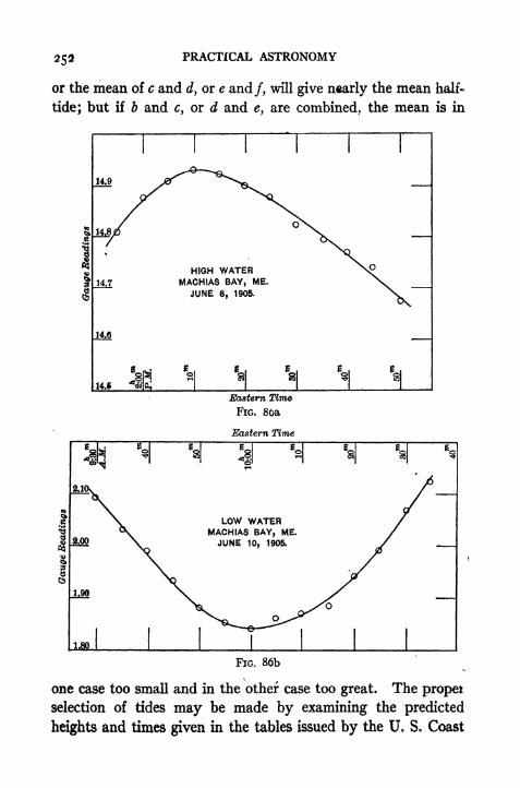
PRACTICAL ASTRONOMY
or the mean of c and d, or e and/, will give nearly the mean half-
tide; but if b and c, or d and e, are combined, the mean is in
HIGH WATERMACHIAS BAY, ME.
JUNE 8, 1905.
14.S "fete
Eastern Time
FIG. 80a
Eastern Time
LOW WATERMACHIAS BAY, ME.JUNE 10, 1905.
1.80
FIG. 86b
one case too small and in the other case too great. The propei
selection of tides may be made by examining the predicted
heights and times given in the tables issued by the U. S. Coast

THE TIDES 253
and Geodetic Survey. By examining the predicted heights the
exact relation may be found between mean sea level and the
jnean half-tide as computed from the predicted heights corre-
sponding 'to those tides actually observed. The difference be-
tween these two may be applied as a correction to the meanof the observed tides to obtain mean sea level. For example,
suppose that the predicted heights at a port near the place of
observation indicate that the mean of a, 6, c, d, e, and /is 0.2 ft.
FIG. 87
below mean sea level. Then if these six tides are observed and
the results averaged, a correction of 0.2 ft. should be added to
the mean of the six heights in order to obtain mean sea level.
Prediction of Tides*
Since the local conditions have such a great influence in
^determiningthe tides at any one place, the prediction of the
times and heights of high and low water for that place must be
based upon a long series of observations made at the same point.
Tide Tables giving predicted tides for one year are published
254 PRACTICAL ASTRONOMY
annually by the United States Coast ancl Geodetic Survey;
these tables give the times and heights of high and low water
for the principal ports of the United States, and also for manyforeign ports. The method of using these tables is explained
in a note at the foot of each page. A brief statement of the
theory of tides is given in the Introduction.
The approximate time of high water at any place may be
computed from the time of the moon's meridian passage, pro-
vided we know the average interval between the moon's transit
and the following high water, i.e., the"establishment of the
port." The mean time of the moon's transit over the meridian
of Greenwich is given in the Nautical Almanac for each day,
together with the change per hour of longitude. The local
time of transit is computed by adding to the tabular time the
hourly change multiplied by the number of hours in the west,
longitude; this result, added to the establishment of the port,
gives the approximate time of high water. The result is nearly
correct at the times of new and full moon, but at other times
is subject to a few minutes variation.
APPENDIX B
SPHERICAL TRIGONOMETRY
The formulae derived in the following pages are those most
frequently used in engineering field practice and in navigation.
Many of the usual formulae of spherical trigonometry are pur-
posely omitted. It is not intended that this appendix shall
serve as a general text book on spherical trigonometry, but merelythat it should supplement that part of the preceding text which
deals with spherical astronomy.A spherical triangle is a triangle formed by arcs of great
circles. If from the vertices of the triangle straight lines are
drawn to the centre of the sphere there is formed at this point a
triedral angle (solid angle) the three face angles of which are
measured by the corresponding sides of the spherical triangle,
and the three diedral angles (edge angles) of which are equal to
the corresponding spherical angles. For any triedral angle a
spherical triangle may be formed, by assuming that the center
of the sphere is at the vertex of the angle, and assigning any
arbitrary value to the radius. The three faces (planes) cut
>out arcs of great circles which form the sides of the triangle.
The solution of the spherical triangle is really at the same time
the solution of the solid angle since the six parts of one equalthe six corresponding parts of the other. Any three lines pass-
ing through a common point define a triedral angle. For example,the earth's axis of rotation, the plumb line at any place on the
surface of the earth, and a line in the direction of the sun's
centre, may be conceived to intersect at the earth's centre.
The relation among the three face angles and the three edge
angles of this triedral angle may be calculated by the formulae
255

256 PRACTICAL ASTRONOMY
of spherical trigonometry. The sphere employed, however, is
merely an imaginary one.
The fundamental formulae mentioned on p. 32 may be derived
by applying the principles of analytic geometry to the1
spherical
triangle. In Fig. 88 the radius of the sphere is assumed to be
unity. If a perpendicular CP be dropped from C to the XYplane, and a line CP' be drawn from C perpendicular to OX
FIG. 88
then x and y may be expressed in terms of the parts of the
spherical triangle as follows:
#= cos a
y = sin a cos Bz = sin a sin B.
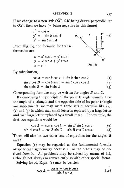
APPENDIX B 257
P'
If we change to a new axis OX', CM being drawn perpendicular
to OX', then we have (/ being negative in this figure)
xf = cos b
y'= sin b cos A
z' = sin b sin A .
From Fig. 89, the formulae for trans-
formation are
x x' cos c yf
sin c
y = x' sin c + y' cos c
z = z. FIG. 89
By substitution,
cos a = cos 6 cos c + sin b sin c cos A (i)
sin a cos B = cos 6 sin c sin & cos c cos ,4 (2)
sin asm B = sin & sin A (3)
Corresponding formulae may be written for angles B and C.
By employing the principle of the polar triangle, namely, that
the angle of a triangle and the opposite side of its polar triangle
are supplements, we may write three sets of formulae like (i),
(2) and (3) in which each small letter is replaced by a large letter
and each large letter replaced by a small letter. For example, the
first two equations would be
cos A = cos B cos C + sin B sin C cos a (a)
sin A cos b = cos B sin C sin B cos C cos a. (b)
^There will also be two other sets of equations for the angles Band C.
Equation (i) may be regarded as the fundamental formula
of spherical trigonometry because all of the others may be de-
rived from it. All problems may be solved by means of (i),
although not always so conveniently as with other special forms.
Solving for A, Equa. (i) may be written
cos a cos b cos ccos A
sin 6 sin c(la)

258 PRACTICAL ASTRONOMY
in which form it may be used to find any angle A when the three
sides are known. See Equa. [20] and [2oa],*and [25] and [250],
pp. 34 and 35. If each side of the equation is subtracted from
unity we have
cos b cos c + sin b sin c cos acos A =
sin b sin c
A cos (b c) cos a,
,
or vers A =-^ -.-
(2)sin b sin. c
or2 sn
2 sn sn
^4
Dividing (3) by 2 and denoting sin2 by"hav." the
"haver-
2
sine," or half versed-sine, we may write
hav. A = sin * (g + b ~ C^ sin * (a"" b + C^
(4)sin 6 sin c
From (2) we may derive [21] and [26] by substituting A =/,
J = 90 5, c = 90 0, and a = 90 h\ or A = Z, b 90
A, c = 90 </>, and a = 90 d.
By putting 5' = | (a + 6 + c), (3) becomes
.4 4 / sin (sf
6) sin (/ c) ,,sm- = W -^- '
.-
(5)2 v sin b sm c
If we add each member of (ia) to unity we may derive by a
similar process
A 4 /sin sf
sin ($' a) ^cos- = U-r-rA--(6)
2 v sin b sin c
Dividing (5) by (6) we have
sm sf sm (/
- a)
Formulae [17], [22], [18], [23], [19] and [24] may be derived
from (5), (6), (7) respectively or, more readily, from the inter-
mediate forms, like (3), by putting s = | (<t> + h + p) and
APPENDIX B 259
A = i or Z. For example, if in (3) we put A =/, a = 90 A,
b = 90 <, and =p, then
-2! = ?in^ (go6 -
/? + 90-
<fr
-ft) sin | (90
- /?- 90
2~~
cos sin ft
__ sin | (180- Q + A + ft) sin H<fr
- ^ + P)
cos < sin ft
Us =%(<!> + k + p) then
2! = cos 5 sin (s /Q
2 cos <t> sin
from which we have [17].
Formula (4) or [17] may be written
hav . , =cos * sin (s
-h)
cos </> sin p
the usual form (in navigation) for the calculation of the hour
angle from an observed altitude of an object.
For the purpose of calculating the great-circle distance be-
tween two points on the earth's surface formula (i) may be putin the form
hav. (dist.)= hav. (j>A <fo) + cos <f>A cos <fo hav. AX (9)
in which 0^, <f>B are the latitudes of two points on the earth's
surface and AX their difference in longitude. <t>A~
<t>B means the
difference between the latitudes if they are both N or both S;
the sum if they are in opposite hemispheres.
Formula (9) is derived by substituting the co-latitudes for
b and c and AX for A in (i) which gives
cos (dist.)= cos (90 <f>A ) cos (90 <fo)
+ sin (90 $A ) sin (90 <t>B) cos AX.
If we add and subtract cos $A cos <t>B in the right-hand memberwe obtain,

260 PRACTICAL ASTRONOMY
cos (dist.)= sin $A sin
<t>s + cos <f>A cos fa cos <f>A cos #5
+ cos 4>A cos <fo cos AX
= cos (<f>A~
<B) cos #4 cos < 5 (i cos AX)
= cos (04 0#) cos 04 cos 0B vers AX.
Subtracting both members from unity
i cos (dist.)== i cos (<t>A 5) + cos <$>A cos B vers AX
or vers (dist.)= vers ($A
~<t>B) + cos <t>A cos <t>B vers AX.
Dividing by 2
hav. (dist.)= hav. ($4 0#) + cos ^ cos <j>B hav. AX. (9)
Note: A table of natural and logarithmic haversines may be
found in Bowditch, American Practical Navigator. (Table 45.)
The same formula may be applied to the calculation of the
zenith distance of an object. In this case it is written
Hav. f = hav. (< 8) + cos < cos <t> hav. t.
'
(10)
This is the formula usually employed in the method of MarcqSaint Hilaire.
Right Triangles
By writing formulae (i), (2), (3), (a) and (&) in terms of the
three parts and placing C - 90, we may obtain the following
ten right triangle formulae.
cos c = cos a cos b
. A sin a . D sinisin A = -: sin B = -;
sin c sin c
A tan b D tan acos A =- cos B =-
tan c tan c
tan a . tan b (n)tan A = -sr tan B =
-r-r-sin sin
ka
. cos B . cos ^4sin A =-r- sm B
cos 6 cos
cos c = cot A cot 5.

APPENDIX B 26l
These are readily remembered from their similarity to the
corresponding formulae of plane triangles.
To solve a right triangle select the three formulae which involve
the two given parts and one of the three parts to be found. Tocheck the results select the formula involving the three parts
just computed. The computed values should satisfy this
equation.
Radians Degrees, Minutes, and Seconds.
If the length of an arc is divided by the radius it expresses
the central angle in radians. The number obtained is the cor-
responding length of arc on a circle whose radius is unity. The
unit of measurement of angles in this system is the radius of
the circle, that is, an angle of i is an angle whose arc equals
the radius, and therefore contains about 57-3.
Since the ratio of the semi-circumference to the radius is ?r,
there are TT radians in 180 of the circumference.* The conversion
of angles from degrees into radians (or -w measure, or arc-measure)
is effected by multiplying by the ratio of these two.
noAngle in degrees = angle in radians X
7T
and'
angle in radians = angle in degrees X -
iSo
To convert an angle in radians into minutes multiply by7T
11
i( T-
3437'-77; or divided by = .0002909. This latterIoO X OO
number, the arc i', is nearly equal to sin i' or tan i'.
To convert an angle expressed in radians into seconds multiply
by = 206264.8; or, divide by the reciprocal,
.00000,48481,36811, the arc i"; this number is identical with
sin i" or tan i" for 16 decimal places.

262 PRACTICAL ASTRONOMY
Area of a Spherical Triangle.
In text books on geometry it is shown tfiat"the area of a
spherical triangle equals its spherical excess times the area of
the tri-rectangular triangle/' the right angle being the unit of
angles. If A represents the area of any spherical triangle, whose
angles are A, B, and C, then
A + B + C ~ 180 4X
or A =
9o' x
8
(A + B + C - 180)
180'
180
,if e is the spherical excess in degrees
_ e"irR2 if e" is the spherical excess in sec-""
180 X 60' X 60"?
onds. (12)
Spherical Excess.
If Equa. (12) is solved for e" we have
_ A 1 80 X 60 X 60e __ x -
A v> , , the constant being the number of sec-= - X 206264.8, , .
&..
R~ onds in one radian
A , x
R* arc i"
Note: Arc i" = .00000,48481,36811; it is the reciprocal of
the above constant, and is the length of the arc 'which subtends
an angle of i" when the radius is unity.
Solid Angles.
Any solid angle* may be measured by an area on the surface
of the sphere in the same manner that plane angles are measured
by arcs on the circumference of a circle. The extent of the
opening between the planes of a triedral angle is proportional to
* A solid angle is one formed by the intersection of any number of planes in a
common point. The triedral angle is a special case of the solid angle.

APPENDIX B 263
the area ot the corresponding spherical triangle, or in other words
proportional to the spherical excess of that triangle. This is
true not only of triangles, but also of spherical polygons and
spherical* areas formed by circles (sectors). The unit of
measurement of the solid angle is the steradian. A unit (plane)
angle is one whose arc is equal in length to the radius of the circle;
that is, it intercepts an arc whose length is R. The steradian is a
solid angle which intercepts on the surface of the sphere an area
equal to Jf?2
;or it intercepts on the sphere of unit radius an area
equal to unity. Just as the plane angle (in radians) when mul-
tiplied by the radius gives the length of arc, so the solid angle or
the spherical excess (in radians) when multiplied by R2gives
the area of the spherical triangle. To obtain a more definite
idea of the size of this angle we may compute the length of arc
from the centre to the circumference of a small circle having an
area equal to R2(or i on a sphere of unit radius). This comes
out about 32 46'+ . The spherical area enclosed by the paral-
lel of latitude 57 14' corresponds to one steradian in the angle
of the cone whose apex is at the centre of the globe.
Functions of Angles near o or 90.When obtaining from tables the values of sines or tangents of
small angles (or angles near to 180) and cosines or cotangents of
angles near to 90 there is some difficulty encountered in the
interpolation, on account of the rapid rate of change of the
logarithms. In practice these values are often found by ap-
proximate methods which enable us to avoid the use of second
differences in the interpolation. There are two assumptions
which may be made, which result in two methods of obtaining
the log functions.
For sines/we may assume that
sin x = x" X sin i"
or log sin x = log x" + log sin i".
The log sin i" = 4.685 5749.
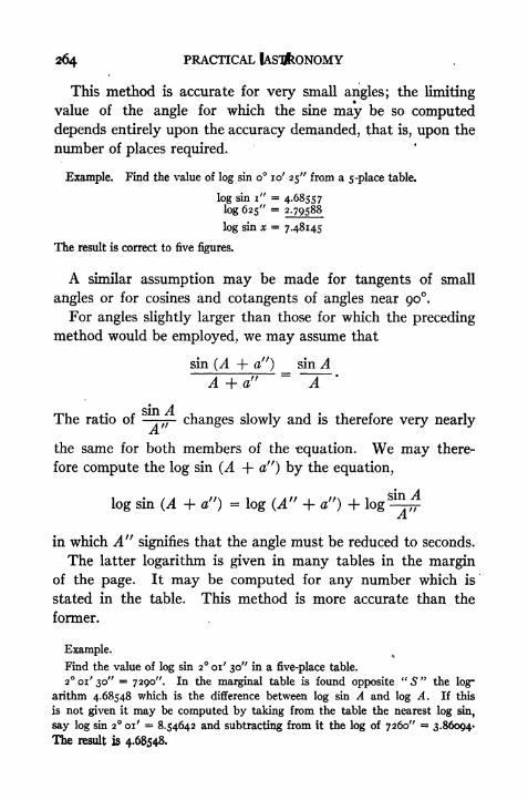
264 PRACTICAL
This method is accurate for very small angles; the limiting
value of the angle for which the sine may be so computed
depends entirely upon the accuracy demanded, that is, upon the
number of places required.
Example. Find the value of log sin o 10' 25" from a 5-place table.
log sin i" = 4-68557log 625" = 2.79588
log sin x = 7.48145
The result is correct to five figures.
A similar assumption may be made for tangents of small
angles or for cosines and cotangents of angles near 90.For angles slightly larger than those for which the preceding
method would be employed, we may assume that
sin (A + a") sin AA + a"
sin AThe ratio of changes slowly and is therefore very nearly
A.
the same for both members of the -equation. We may there-
fore compute the log sin (A + a") by the equation,
log sin (A + a!'}= log (A" + a") + log
8
-^in which A 11
signifies that the angle must be reduced to seconds.
The latter logarithm is given in many tables in the marginof the page. It may be computed for any number which is
stated in the table. This method is more accurate than the
former.
Example.
Find the value of log sin 2 01' 30" in a five-place table.
2 01' 30" = 7290". In the marginal table is found opposite" S "
the log-
arithm 4.68548 which is the difference between log sin A and log A. If this
is not given it may be computed by taking from the table the nearest log sin,
say log sin 2 01' = 8.54642 and subtracting from it the log of 7260" 3.86004*
The result is 4.68548.
APPENDIX B 265
Then
log^- 4.68548
log 7290" - 3-86273
log sin x ~ 8.54821
This result is correct to five figures.


INDEX
Aberration of light, 1 2
Adjustment of transit, 92, 98, 130
Almucantar^ 15
Altitude, 19
of pole, 27
Angle of the vertical, 80
Annual aberration, 13
Aphelion, 9
Apparent motion, 3, 28
time, 42
Arctic circle, 30
Aries, first point of, 16, 113
Astronomical time, 46
latitude, 79
transit, 96, 130
triangle, 31, 134Atlantic time, 50Attachments to transit, 95
Autumnal equinox, 16
Axis, 3, 8
Azimuth, 19, 161
mark, 161
tables, 77, 149, 214, 223
B
yBearings, 19
Besselian year, 68
Calendar, 62
Celestial latitude and longitude, 22
sphere, i
Central time, 50I Charts, 223
Chronograph, 105, 130, 152, 155
Chronometer, 58, 104, 108, 130, 155
correction, 127
sight, 213
267
Circum-meridian altitude, 123, 212
Circumpolar star, 29, 115, 181
Civil time, 46
Clarke spheroid, 79
Coast and Geodetic Survey, 99, 121,
171, 185, 247
Co-latitude, 22
Comparison of chronometer, 104
Constant of aberration, 13
Constellations, 10, noConvergence of meridians, 206
Cross hairs, 91, 96
Culmination, 40, 115, 128
Curvature, 134, 183, 184
DDate line, 61
Daylight saving time, 52
Dead reckoning, 213
Decimation, 20
parallels of, 16
Dip, 88
Diurnal aberration, 13, 185
inequality, 246
Eastern time, 50
Ebb tide, 244
Ecliptic, 16, 112, 114
Ellipsoid, 79
Elongation, 36, 162
Ephemeris, 65
Equal altitude method, 143, 195, 196
Equation of time, 42
Equator, 15
systems, 19
Equinoxes, 9, 16, 41
Errors in horizontal angle, 108
in spherical triangle, 139, 178
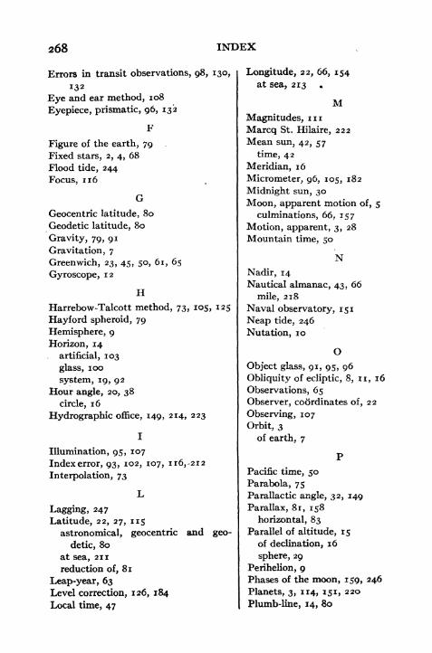
268 INDEX
Errors in transit observations, 98, 130,
132
Eye and ear method, 108
Eyepiece, prismatic, 96, 132
Figure of the earth, 79
Fixed stars, 2, 4, 68
Flood tide, 244
Focus, 116
Geocentric latitude, 80
Geodetic latitude, 80
Gravity, 79, 91
Gravitation, 7
Greenwich, 23, 45, 50, 61, 65
Gyroscope, 12
HHarrebow-Talcott method, 73, *O5
Hayford spheroid, 79
Hemisphere, 9
Horizon, 14
artificial, 103
glass, loo
system, 19, 92Hour angle, 20, 38
circle, 16
Hydrographic office, 149, 214, 223
Illumination, 95, 107
Index error, 93, 102, 107, ir6r2i2
Interpolation, 73
Lagging, 247
Latitude, 22, 27, 115
astronomical, geocentric and geo-
detic, 80
at sea, 211
reduction of, 81
Leap-year, 63Level correction, 126, 184
Local time, 47
Longitude, 22, 66, 154at sea, 213
MMagnitudes, inMarcq St. Hilaire, 222
Mean sun, 42, 57
time, 42
Meridian, 16
Micrometer, 96, 105, 182
Midnight sun, 30
Moon, apparent motion of, 5
culminations, 66, 157
Motion, apparent, 3, 28
Mountain time, 50
NNadir, 14
Nautical almanac, 43, 66
mile, 218
Naval observatory, 151
Neap tide, 246
Nutation, 10
OObject glass, 91, 95, 96
Obliquity of ecliptic, 8, n, 16
Observations, 65
Observer, coordinates of, 22
Observing, 107
Orbit, 3
of earth, 7
Pacific time, 50
Parabola, 75
Parallactic angle, 32, 149
Parallax, 81, 158
horizontal, 83
Parallel of altitude, 15
of declination, 16
sphere, 29
Perihelion, 9Phases of the moon, 159, 246
Planets, 3, 114, 151, 220
Plumb-line, 14, 80
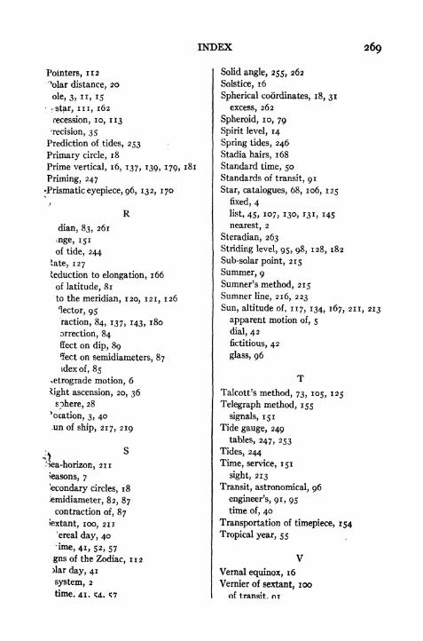
INDEX 269
Pointers, 112
\>lar distance, 20
ole, 3, ii, 15
r star, in, 162
recession, 10, 113
-recision, 35
Prediction of tides, 253
Primary circle, 18
Prime vertical, 16, 137, 139, 179, 181
Priming, 247
"Prismatic eyepiece, 96, 132, 170
/
R
dian, 83, 261
inge, 151
of tide, 244
late, 127
'eduction to elongation, 166
of latitude, 81
to the meridian, 120, 121, 126
lector, 95
raction, 84, 137, 143, 180
orrection, 84
ffect on dip, 89
5ect on semidiameters, 87
idex of, 85
vetrograde motion, 6
light ascension, 20, 36
sphere, 28
^ocation, 3, 40.un of ship, 217, 219
Sea-horizon, 211
Reasons, 7
Secondary circles, 18
)emidiameter, 82, 87
contraction of, 87
Jextant, 100, 211
'ereal day, 40
ime, 41, 52, 57
gns of the Zodiac, 112
Mar day, 41
system, 2
time. AI. <M. S7
Solid angle, 255, 262
Solstice, 16
Spherical coordinates, 18, 31
excess, 262
Spheroid, 10, 79
Spirit level, 14
Spring tides, 246
Stadia hairs, 168
Standard time, 50
Standards of transit, 91
Star, catalogues, 68, 106, 125
fixed, 4
list, 45, 107, 130, 131, 145
nearest, 2
Steradian, 263
Striding level, 95, 98, 128, 182
Sub-solar point, 215
Summer, 9
Sumner's method, 215
Sumner line, 216, 223
Sun, altitude of, 117, 134, 167, 211, 213
apparent motion of, 5
dial, 42
fictitious, 42
glass, 96
Talcott's method, 73, 105, 125
Telegraph method, 155
signals, 151
Tide gauge, 249
tables, 247, 253
Tides, 244
Time, service, 151
sight, 213
Transit, astronomical, 96
engineer's, 91, 95
time of, 40
Transportation of timepiece, 154
Tropical year, 55
VVernal equinox, 16
Vernier of sextant, 100
of transit. OT
INDEX
Vertical circle, 14, 140
line, 14Visible horizon, 14
WWashington, 45, 66
Watch correction, 129, 151
Winter, 8
Wireless telegraph signals, 151, 156
Year, 55, 68
Zenith, 14
distance, 19
telescope, 105, 125
Zodiac, 112