
19080432 rrc-procedures-in-lte-comments-v1-121115125316-phpapp02
22
RRC PROCEDURES IN LTE Version 0.1 Revision History: © Hughes Systique India Private Limited, India
-
Upload
divyansh-gupta -
Category
Mobile
-
view
37 -
download
0
Transcript of 19080432 rrc-procedures-in-lte-comments-v1-121115125316-phpapp02

RRC PROCEDURES IN LTE
Version 0.1
Revision History:
© Hughes Systique India Private Limited, India

Version Date Description Author0.1 22-APR-2008 Initial Draft Praveen Kumar0.2 23-APR-2008 Incorporated
pradeep’s commentPraveen Kumar
ntents
© Hughes Systique India Private Limited, India
1 Introduction ....................................................................................................................... 6 2 Purpose .............................................................................................................................. 6 3 Important Changes in RRC specification for LTE and its difference with legacy 3G-RNC system ......................................................................................................................... 6 4 Architecture ....................................................................................................................... 9
4.1 RRC State ................................................................................................................... 9 4.2 Signaling Radio Bearers ............................................................................................ 9 4.3 RRC Functions ......................................................................................................... 10 4.4 RRC Procedures ....................................................................................................... 11
4.4.1 Paging ............................................................................................................... 11 4.4.2 RRC Connection establishment ........................................................................ 12 4.4.3 RRC Connection Reconfiguration .................................................................... 14 4.4.4 RRC Connection Re-establishment ................................................................. 16 4.4.5 Initial Security Activation ................................................................................. 17 4.4.6 RRC Connection Release .................................................................................. 18 4.4.7 DL Information Transfer ................................................................................... 18 4.4.8 UL Information Transfer ................................................................................... 19 4.4.9 Handover Procedure .......................................................................................... 20
.......................................................................................................................................... 22
ReferenceDocument Name References in Document Date Version
RRC Specification 33.331 v
© Hughes Systique India Private Limited, India

from 3GPP – Release 8
8.1.0
Abbreviations:
ARQ Automatic Repeat QueryHARQ Hybrid Automatic Repeat QueryAM Acknowledged ModeASN.1 Abstract Syntax Notation.1ARQ Automatic Repeat RequestAS Access StratumBCCH Broadcast Control ChannelBCH Broadcast ChannelCCCH Common Control ChannelCCO Cell Change OrderCP Control PlaneC-RNTI Cell RNTICSG Closed Subscriber GroupDCCH Dedicated Control ChannelDRB (user) Data Radio BearerDRX Discontinuous ReceptionDTCH Dedicated Traffic ChannelDTX Discontinuous TransmissionDL DownlinkDL-SCH Downlink Shared ChannelE-UTRA Evolved Universal Terrestrial Radio AccessE-UTRAN Evolved Universal Terrestrial Radio Access NetworkENB Evolved Node BEPC Enhanced Packet CoreEPS Enhanced Packet SystemFDD Frequency Division DuplexFFS For Further StudyGERAN GSM/EDGE Radio Access NetworkGSM Global System for Mobile CommunicationsHARQ Hybrid Automatic Repeat RequestHRPD CDMA2000 High Rate Packet DataIE Information elementIMEI International Mobile Equipment IdentityIMSI International Mobile Subscriber IdentityL1 Layer 1L2 Layer 2L3 Layer 3MAC Media Access ControlMBMS Multimedia Broadcast Multicast ServiceMCCH MBMS point-to-multipoint Control ChannelMIB Master Information Block
© Hughes Systique India Private Limited, India

MTCH MBMS point-to-multipoint Traffic ChannelN/A Not ApplicableNACC Network Assisted Cell ChangeNAS Non Access StratumPCCH Paging Control ChannelPDU Protocol Data UnitPDCP Packet Data Convergence ProtocolPLMN Public Land Mobile NetworkPTM-MC Point-to-Multipoint, Multi-CellPTM-SC Point-to-Multipoint, Single-CellPTP Point-to-PointQoS Quality of ServiceRACH Random Access ChannelRA-RNTI Random Access RNTIRAT Radio Access TechnologyRB Radio BearerRLC Radio Link ControlRNTI Radio Network Temporary IdentifierRRC Radio Resource ControlRSCP Received Signal Code PowerRSRP Reference Signal Received PowerRSSI Received Signal Strength IndicatorSAE System Architecture EvolutionSAP Service Access PointSI Scheduling InformationSIB System Information BlockSI-RNTI Scheduling Information Change RNTISI-RNTI Scheduling Information RNTISRB Signaling Radio BearerS-TMSI SAE Temporary Mobile Station IdentifierTA Tracking AreaTDD Time Division DuplexTM Transparent ModeUE User EquipmentUICC Universal Integrated Circuit CardUL UplinkUM Unacknowledged ModeUL-SCH Uplink Shared ChannelUP User Plane
© Hughes Systique India Private Limited, India

1 Introduction
This document provides the details of RRC procedures as specified in 3GPP 36.331 for LTE.
2 Purpose
The purpose of this document is to understand RRC Procedures and RRC IEs for LTE. It will help developers and testing engineer to understand the feature better and utilize their knowledge in various customer sites. This document will also help developer to start thinking design of RRC in LTE.
3 Important Changes in RRC specification for LTE and its difference with legacy 3G-RNC system
Following is the important changes in RRC specification for LTE and its difference with legacy 3G-RNC system. Procedure specific difference is mentioned in specific procedure section.
• RRC State: - In LTE there is only 2 RRC states i.e. RRC_IDLE and RRC_CONNECTED whereas in 3G-RNC system RRC has a 5 state i.e. IDLE, CELL_FACH, CELL_DCH, CELL_PCH, URA_PCH. In LTE, there is no concept of common and dedicated transport channel, that’s why there is no need of CELL_FACH and CELL_DCH state. In LTE there is only shared transport channel are defined. CELL_PCH and URA_PCH is also removed because in LTE. Therefore this will simplifies the RRC State machine handling and improves RRC performance. This will also simplify the RRM algorithm which decides RRC states.
• Signaling Radio Bearers: - In LTE there is only three SRB is defined i.e. SRB0, SRB1 and SRB2. Still SRB2 is on FFS, whereas in 3G-RNC system RRC has 4 SRBs i.e. SRB0, SRB1, SRB2 and SRB3 (optional).
• SRB 0: - In LTE SRB 0 is used RLC TM entity over CCCH logical channel in DL whereas in 3G-RNC system RLC UM entity over CCCH logical channel in DL.
• MAC entity: - In LTE there is only one MAC entity which needs to configured whereas in 3G-RNC system there is 4 different MAC entity based on different type of transport channel i.e MAC-d (DCH), MAC-c/sh (FACH, DSCH), MAC-hs (HS-DSCH) and MAC-e (E-DCH). In 3G-RNC system the state machine which is handling MAC configuration is quite complex. During state transition CELL_FACH->CELL_DCH or CELL_DCH->CELL_FACH lots of signaling was involved. In LTE, since there is only one MAC entity which is easier and simple to configure and have very simple State Machine.
© Hughes Systique India Private Limited, India

• Radio Bearer mapping: - In LTE Radio bearer mapping would be much simpler than the 3G-RNC system because of there is no common and transport channel defined in LTE.
• In LTE there is no RRC connection mobility defined like cell update and ura update.
• Domain Identity: - In LTE, there is only one domain identity i.e. PS domain and which is implicit no need to specify anywhere in signaling where as in 3G-RNC system there is two domain identity i.e. CS domain and PS domain identity. Because of these two identities, there was lot of signaling overhead and complexity in RRC design. Now in LTE, there is no Initial UE Message is defined because only one domain identity is there.
• System Broadcast Information:- In LTE, MIB includes a limited number of most frequently transmitted parameters and SIB Type 1containing the scheduling information that mainly indicates when the SI messages are transmitted where as in 3G-RNC system, MIB includes the frequently transmitted parameters was well as scheduling information.
• In LTE, only shared channel is defined, so UE is always listening/decoding to the radio frame at L1 and L2 layer, there is no need to define the downlink transport channel configuration in the RRC Reconfiguration message. This will reduce signaling message size effectively. All DL-SCH transport channel information is broadcasted in system information.
• The above point introduces another very critical feature of DRX calculation since all DL data is on the shared channel. ENB can tell the UE when to decode/listen over the radio frame. This will optimize UE power consumtion.
• Paging Type: - In LTE there is only one type of paging required where as in 3G-RNC system there is two type of paging defined. This is because there is no CELL_FACH and CELL_DCH state in LTE.
• Less signaling message in case of Reconfiguration: - In LTE there is only one reconfiguration message to reconfigure all logical, transport and physical channel where as in 3G-RNC system there are number of reconfiguration message i.e. RB reconfiguration , TRCH configuration, PHY configuration.
• In LTE there is no NBAP protocol, this reduces the latency of the RRC connection establishment and RB management procedure.
• There is no need to define URNTI, ERNTI, HRNTI, SRNTI in LTE, since there is only one shared MAC entity.
• In LTE, there in no need to define activation time. Because of this there are lots of synchronizing complexity in 3G-RNC systems i.e. Synchronizing Radio link procedure based on activation time, synchronizing between the various MAC entity. This reduces significantly latency during establishment and reconfiguration of radio bearers.
• In LTE, there in no need to specify the RRC State in RRC message. • For network control mobility, there is one feature which become very
important and critical i.e. CQI Reporting. CQI reporting should be fast and correct for taking decision for mobility.
© Hughes Systique India Private Limited, India

• There is no signaling connection release procedure in LTE, since there is only one domain i.e. PS domain and the UE context is shared between the MME and ENB and if UE is active in ENB then it should be active in MME also.
© Hughes Systique India Private Limited, India

4 Architecture
4.1 RRC StateUE has two RRC state
• RRC_IDLE:- This state indicates that there is not signaling radio bearer is established i.e. no RRC connection is established. RRC_IDLE state can further characterized as follows
o Transfer of broadcast/multicast data to UE.o A UE specific DRX may be configured by upper layers.o UE controlled mobility.o The UE:
Monitors control channels associated with the shared data channel to determine if data is scheduled for it.
Performing neighboring cell measurements and measurement reporting.
Acquires system information.
• RRC_CONNECTED: - This state indicates that there is signaling radio bearer established i.e. RRC connection is established. RRC_CONNECTED state can be further characterized as follows
o Transfer of unicast data to/from an UE, transfer of broadcast/multicast data to UE.
o At the lower layers, the UE may configure with a UE specific DRX/DTX.
o Network Control Mobility, i.e. handover and cell change order with network assistance (NACC) to GEREN.
o The UE:
Monitors control channels associated with the shared data channel to determine if data is scheduled for it
Provides channel quality and feedback information. Performing neighboring cell measurements and measurement
reporting. Acquires system information.
4.2 Signaling Radio Bearers"Signaling Radio Bearers" (SRBs) are defined as Radio Bearers (RB) that are used only for the transmission of RRC and NAS messages. More specifically, the following three SRBs are defined: - SRB0 is for RRC messages using the CCCH logical channel;- SRB1 is for NAS messages and for most RRC messages, all using DCCH logical
channel;- SRB2 is for high-priority RRC messages, using DCCH logical channel.
© Hughes Systique India Private Limited, India
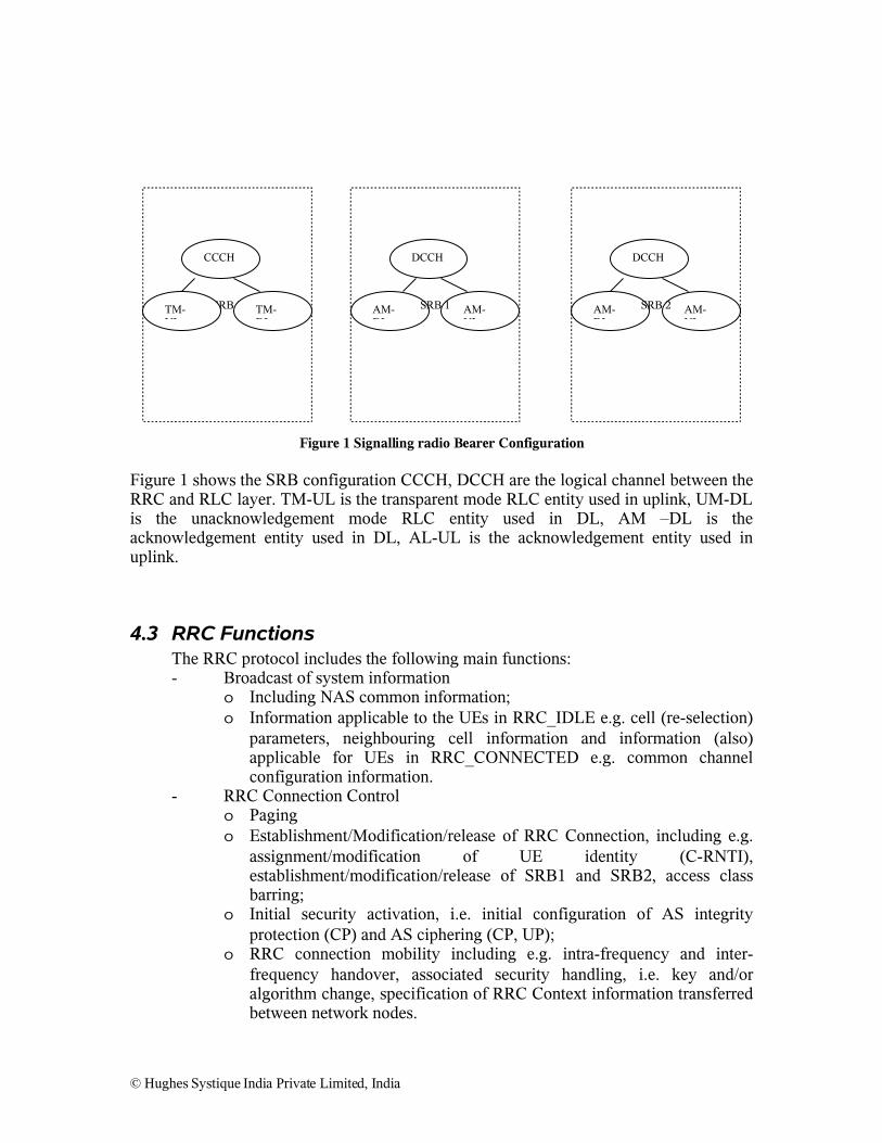
Figure 1 Signalling radio Bearer Configuration
Figure 1 shows the SRB configuration CCCH, DCCH are the logical channel between the RRC and RLC layer. TM-UL is the transparent mode RLC entity used in uplink, UM-DL is the unacknowledgement mode RLC entity used in DL, AM –DL is the acknowledgement entity used in DL, AL-UL is the acknowledgement entity used in uplink.
4.3 RRC FunctionsThe RRC protocol includes the following main functions:- Broadcast of system information
o Including NAS common information;o Information applicable to the UEs in RRC_IDLE e.g. cell (re-selection)
parameters, neighbouring cell information and information (also) applicable for UEs in RRC_CONNECTED e.g. common channel configuration information.
- RRC Connection Controlo Pagingo Establishment/Modification/release of RRC Connection, including e.g.
assignment/modification of UE identity (C-RNTI), establishment/modification/release of SRB1 and SRB2, access class barring;
o Initial security activation, i.e. initial configuration of AS integrity protection (CP) and AS ciphering (CP, UP);
o RRC connection mobility including e.g. intra-frequency and inter-frequency handover, associated security handling, i.e. key and/or algorithm change, specification of RRC Context information transferred between network nodes.
© Hughes Systique India Private Limited, India
SRB 0 TM-DL
AM-DL
AM-UL
AM-DL
AM-UL
TM-UL
CCCH
SRB 1 SRB 2
DCCH DCCH

o Establishment/modification/release of point to point RBs carrying user data.
o Radio configuration control including e.g. assignment/modification of ARQ configuration, HARQ configuration , DRX configuration;
o QoS Control including assignment/modification of semi-persistent configuration information of DL/UL assignment/modification of parameters for UL rate control in the UE, i.e. allocation of a priority and a prioritized bit rate (PBR) for each RB.
o Recovery from Radio link Failure.- Inter-RAT mobility including e.g. security activation, transfer of RRC
context information.- Measurement configuration control and reporting:
o Establishment/modification/release of measurements (e.g. Intra frequency, inter frequency and inter RAT mobility, Quality, UE internal, positioning)
o Configuration and deactivation of measurement gaps;o Measurement Reporting
- Other functions including e.g. transfer of dedicated NAS Information and non-3GPP dedicated information, transfer of UE Radio access capability information, and support for E-UTRAN sharing (multiple PLMN identities).
- Multicast/Broadcast- Support of self configuration and self-optimisation.
4.4 RRC Procedures
4.4.1 Paging
PAGING
UE EUTRAN
Figure 2 Paging Procedure
The purpose of paging- Transmit paging information to the UE in RRC_IDLE state.- To inform UEs in RRC_IDLE about the system information change.
Paging message include paging records for UE which is to be paged. RRC needs to configure the one TM RLC entity over PCCH logical channel to send the paging message to the UE.
© Hughes Systique India Private Limited, India
4.4.1.1 Differences with 3G-RNC System in PagingIn 3G-RNC system, there is two type of paging is defined i.e. paging Type 1 (idle, CELL_PCH, URA_PCH) and paging Type 2 (CELL_DCH, CELL_FACH) and these paging are specific to the CN Domain. In LTE this has become simpler because there is only one domain and there is no state like CELL_PCH and URA_PCH. In LTE paging is handled in RRC_IDLE state.
4.4.2 RRC Connection establishment
RRC CONNECTION SETUP
RRC CONNECTION REQUEST
UE EUTRAN
RRC CONNECTION SETUP COMPLETE
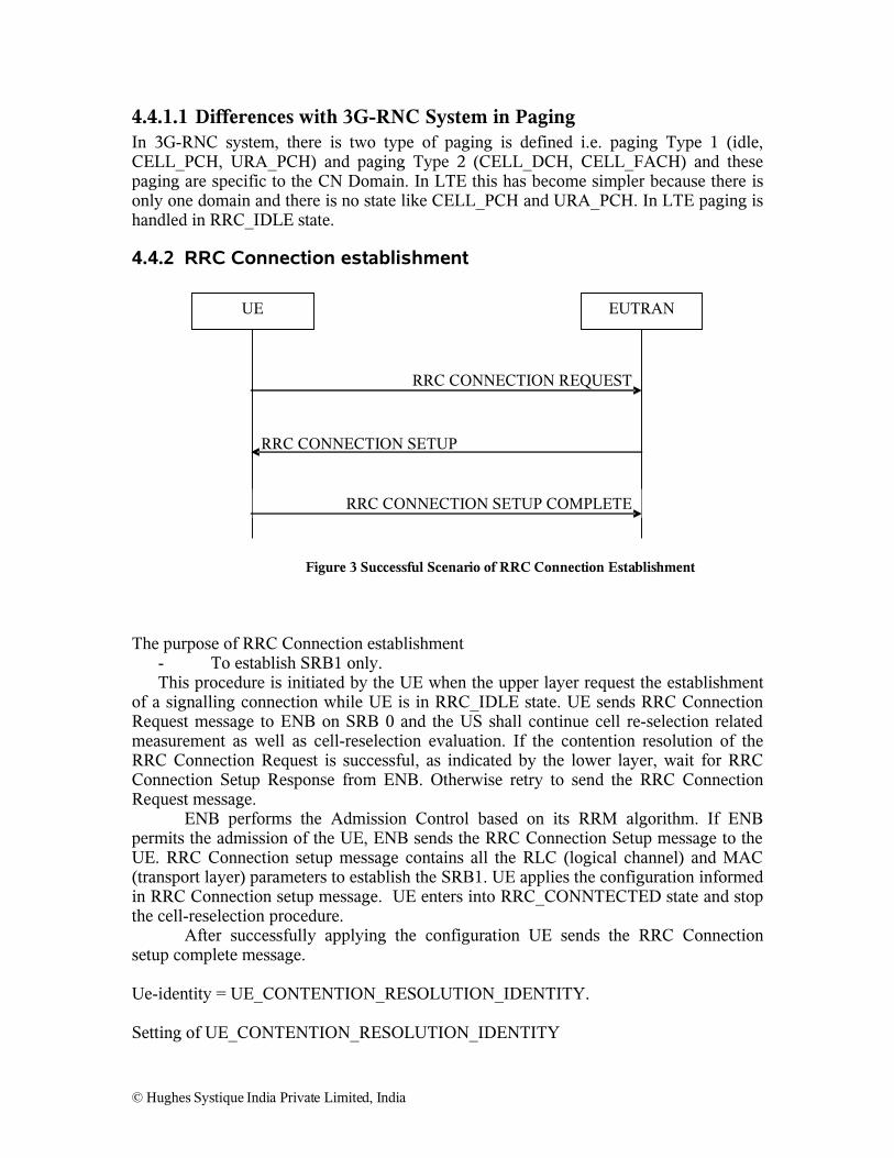
Figure 3 Successful Scenario of RRC Connection Establishment
The purpose of RRC Connection establishment- To establish SRB1 only.This procedure is initiated by the UE when the upper layer request the establishment
of a signalling connection while UE is in RRC_IDLE state. UE sends RRC Connection Request message to ENB on SRB 0 and the US shall continue cell re-selection related measurement as well as cell-reselection evaluation. If the contention resolution of the RRC Connection Request is successful, as indicated by the lower layer, wait for RRC Connection Setup Response from ENB. Otherwise retry to send the RRC Connection Request message.
ENB performs the Admission Control based on its RRM algorithm. If ENB permits the admission of the UE, ENB sends the RRC Connection Setup message to the UE. RRC Connection setup message contains all the RLC (logical channel) and MAC (transport layer) parameters to establish the SRB1. UE applies the configuration informed in RRC Connection setup message. UE enters into RRC_CONNTECTED state and stop the cell-reselection procedure.
After successfully applying the configuration UE sends the RRC Connection setup complete message.
Ue-identity = UE_CONTENTION_RESOLUTION_IDENTITY.
Setting of UE_CONTENTION_RESOLUTION_IDENTITY
© Hughes Systique India Private Limited, India

- If upper layer provides an S-TMSI. Upper layer will provide the S-TMSI if the UE is registered in the TA of the current cell.o Set Identity Type to “S-TMSI”o Set the “S-TMSI” to the value received from upper layer.
- Elseo Set the identity type to “random number”o Draw a random value and set the “Random number” to the selected value.
RRC CONNECTION REJECT
RRC CONNECTION REQUEST
UE EUTRAN
Figure 4 RRC connection establishment, network reject
ENB can reject the RRC connection establishment based on its admission control algorithm. In this case ENB sends RRC Connection Reject message to the UE.
4.4.2.1 Difference with 3G-RNC system in RRC Connection Establishment Procedure• RRC Connection Request is very small in size in LTE as compared to 3G-
RNC. The main difference in both cases is the usage of UE identity. In LTE UE identity is used as contention resolution identity because this is first message from UE on the shared uplink channel where as in 3G RNC UE identity is the initial UE identity. In LTE many IE have been removed from RRC Connection Request message i.e. CN Domain Identity, Call type, HS-PDSCH in CELL_FACH, MAC-ehs support, Access Stratum release indicator, support of F-DPCH, UE mobility state indicator, Measured result on RACH.
• In LTE UE identity is used as contention resolution identity. It is possible that contention failure can happen; in this case UE will try again the RRC connection request based on its timer and counter. RRC will come to know about the contention result from random access response message from peer MAC layer. In this procedure there is interaction with the MAC layer where as in 3G-RNC there is no such interaction with the MAC layer.
• In LTE C-RNTI is indirectly allocated by MAC layer where as in 3G-RNC system C-RNTI is allocated by the RRC layer and indicates to the MAC layer. During random access procedure MAC Layer provides T-CRNTI to the UE and UE uses this T-CRNTI as a CRNTI after successfully completion of the RRC Connection establishment procedure.
© Hughes Systique India Private Limited, India

• In LTE the default configuration is used for the radio bearer parameters. There is no explicit configuration possible for RB where as in 3G-RNC system explicit configuration is possible. The number of default configuration in LTE is under FFS.
• RRC Connection Setup Complete message include the nasDedicationInfomation IE which will reduce the NAS signalling delay. In 3G-RNC system the nas information is sent via uplink direct transfer message.
Question• Why there is no UE capabilities information in RRC Connection Setup
Complete message • There is no START value defined in RRC Connection Setup Complete. In
3G-RNC system START value is defined for each domain. But I do not know how this is handled in the LTE.
4.4.3 RRC Connection Reconfiguration
The purpose of this procedure - Establish/modify/release RBs,- To perform Handover- To configure/modify measurements- NAS dedicated information may be transferred from ENB to UE.
If AS-Security is enabled then only include Mobility Control Information IE and IEs related to the RB establishment.
RRC CONNECTION RECONFIGURATION COMPLETE
RRC CONNECTION RECONFIGURATION
UE EUTRAN
Figure 5 RRC connection reconfiguration, successful
© Hughes Systique India Private Limited, India

RRC CONNECTION RECONFIGURATION FAILURE
RRC CONNECTION RECONFIGURATION
UE EUTRAN
Figure 6 RRC connection reconfiguration, failure
RRC Connection Reconfiguration message is used to establish one or more RBs. In this procedure following broad level IEs are included.
• Measurement Configuration • Nas dedicated information.• Radio Resource Configuration.• Mobility Control information.• Security Configuration• UE Related Information.
If UE successfully applied the configuration, It sends RRC Connection Reconfiguraion Complete, otherwise RRC Connection Reconfiguration Fail
4.4.3.1 Difference with 3G-RNC system in RRC Connection Reconfiguration Procedure
• In LTE, the prioritized bit rate is introduced in Uplink. The UE has an uplink rate control function which manages the sharing of uplink resources between radio bearers. RRC controls the uplink rate control function by giving each bearer a priority and a prioritized bit rate (PBR). PBR is a parameter set internal to the ENodeB and is not signaled over the S1 interface as QoS parameter. The uplink rate control function ensures that the UE serves its radio bearer(s) in the following sequence:
o All the radio bearer(s) in decreasing priority order up to their PBR;o All the radio bearer(s) in decreasing priority order for the remaining
resources assigned by the grantNOTE: In case the PBRs are all set to zero, the first step is skipped and the
radio bearer(s) are served in strict priority order: the UE maximizes the transmission of higher priority data• Since LTE is having only one state in RRC connected mode i.e.
RRC_CONNECTED, that’s why the complexity is reduced significantly as compared to the 3G-RNC.
• In LTE there is only one message define for the reconfiguration where as in 3G-RNC system 3 procedures are there to change the radio bearer
© Hughes Systique India Private Limited, India
configurations i.e radio bearer reconfiguration, transport channel reconfiguration and physical channel reconfiguration.
• RB mapping Info is much simpler as compared to the 3G-RNC system.• Transport channel and physical channel information IE is significantly
reduced as compared to the 3G-RNC system due to use of shared transport and physical channel. There is no common and dedicated transport and physical channel define in LTE.
• In LTE, at RRC level only one RNTI is maintained i.e. CRNTI which is generated by MAC layer and informed to RRC Layer.
• In LTE, there is provision to change the security configuration using RRC Connection Reconfiguration where as in 3G-RNC system, it was handled using security mode command procedure.
• In LTE, RRC Connection reconfiguration can be also used to send NAS dedicated signalling to the MS to reduce the latency where as this option is not in 3G-RNC system.
4.4.4 RRC Connection Re-establishment
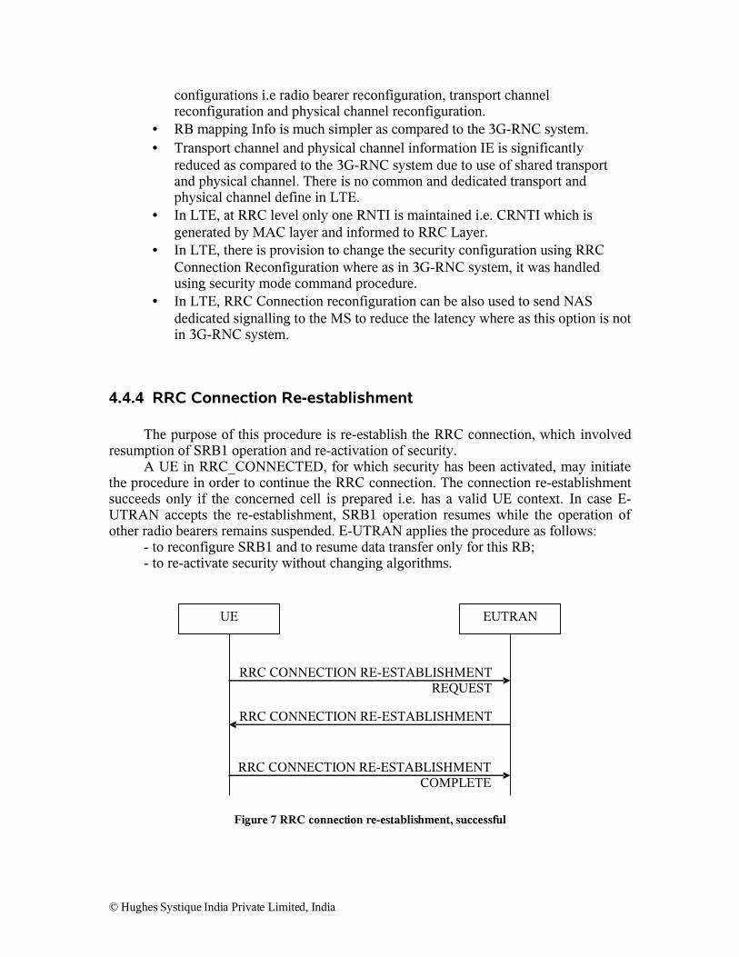
The purpose of this procedure is re-establish the RRC connection, which involved resumption of SRB1 operation and re-activation of security.
A UE in RRC_CONNECTED, for which security has been activated, may initiate the procedure in order to continue the RRC connection. The connection re-establishment succeeds only if the concerned cell is prepared i.e. has a valid UE context. In case E-UTRAN accepts the re-establishment, SRB1 operation resumes while the operation of other radio bearers remains suspended. E-UTRAN applies the procedure as follows:
- to reconfigure SRB1 and to resume data transfer only for this RB;- to re-activate security without changing algorithms.
RRC CONNECTION RE-ESTABLISHMENT REQUEST
UE EUTRAN
RRC CONNECTION RE-ESTABLISHMENT
RRC CONNECTION RE-ESTABLISHMENT COMPLETE
Figure 7 RRC connection re-establishment, successful
© Hughes Systique India Private Limited, India

RRC CONNECTION RE-ESTABLISHMENT REQUEST
UE EUTRAN
RRC CONNECTION RE-ESTABLISHMENT REJECT
Figure 8 RRC connection re-establishment, successful
The UE shall initiate this procedure when security as been activated. The UE initiates the procedure when one of the following conditions is met:- Upon re-entry of the service area after having detected radio link failure;- Upon handover failure- When lower layers detect problems, as specified in TS 36.322 [7];
4.4.4.1 Difference with 3G-RNC system in RRC Connection Reestablishment Procedure
• In 3G-RNC System, for indicating radio link failure and lower layers failure CELL UPDATE procedure is used where as in LTE RRC Connection reestablishment procedure is used.
• The handling of Radio Link Failure case is still FFS. There are various proposals for handling radio link failure going on.
4.4.5 Initial Security Activation
The purpose of this procedure is to activate AS security upon RRC connection establishment. ENB initiates the security mode command procedure to a UE in RRC_CONNECTED. Moreover, ENB applies the procedure as follows:- When only SRB1 is established, i.e. prior to establishment of SRB2 and/ or
DRBs.
SECURITY MODE COMPLETE
SECURITY MODE COMMAND
UE EUTRAN
Figure 9 Security mode command, successful
© Hughes Systique India Private Limited, India

SECURITY MODE FAILURE
SECURITY MODE COMMAND
UE EUTRAN
Figure 10 Security Mode command, failure
RRC Specification for LTE does not specify about the START value. The security specification is also under FFS.
4.4.6 RRC Connection ReleaseThe purpose of this procedure is to release the RRC connection, which includes the release of the signaling connection, the established EPS bearers as well as all radio resources. E-UTRAN initiates the RRC connection release procedure to a UE in RRC_CONNECTED. It is FFS if redirection can be done from E-UTRAN before security is activated.
RRC CONNECTION RELEASE
UE EUTRAN
Figure 11 RRC connection release, successful
4.4.7 DL Information TransferThe purpose of this procedure is to transfer NAS or (tunnelled) non-3GPP dedicated information from E-UTRAN to a UE in RRC_CONNECTED. E-UTRAN initiates the DL information transfer procedure whenever there is a need to transfer NAS or non-3GPP dedicated information. E-UTRAN initiates the DL information transfer procedure by sending the DL INFORMATION TRANSFER message.
DL INFORMATION TRANSFER
UE EUTRAN
© Hughes Systique India Private Limited, India
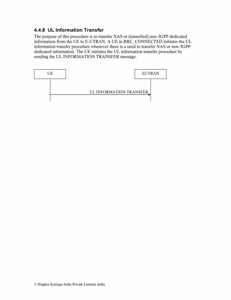
4.4.8 UL Information TransferThe purpose of this procedure is to transfer NAS or (tunnelled) non-3GPP dedicated information from the UE to E-UTRAN. A UE in RRC_CONNECTED initiates the UL information transfer procedure whenever there is a need to transfer NAS or non-3GPP dedicated information. The UE initiates the UL information transfer procedure by sending the UL INFORMATION TRANSFER message.
UL INFORMATION TRANSFER
UE EUTRAN
© Hughes Systique India Private Limited, India
4.4.9 Handover Procedure
4.4.9.1 Handover from E-UTRA to other RAT (UTRAN/GERAN/CDMA2000)
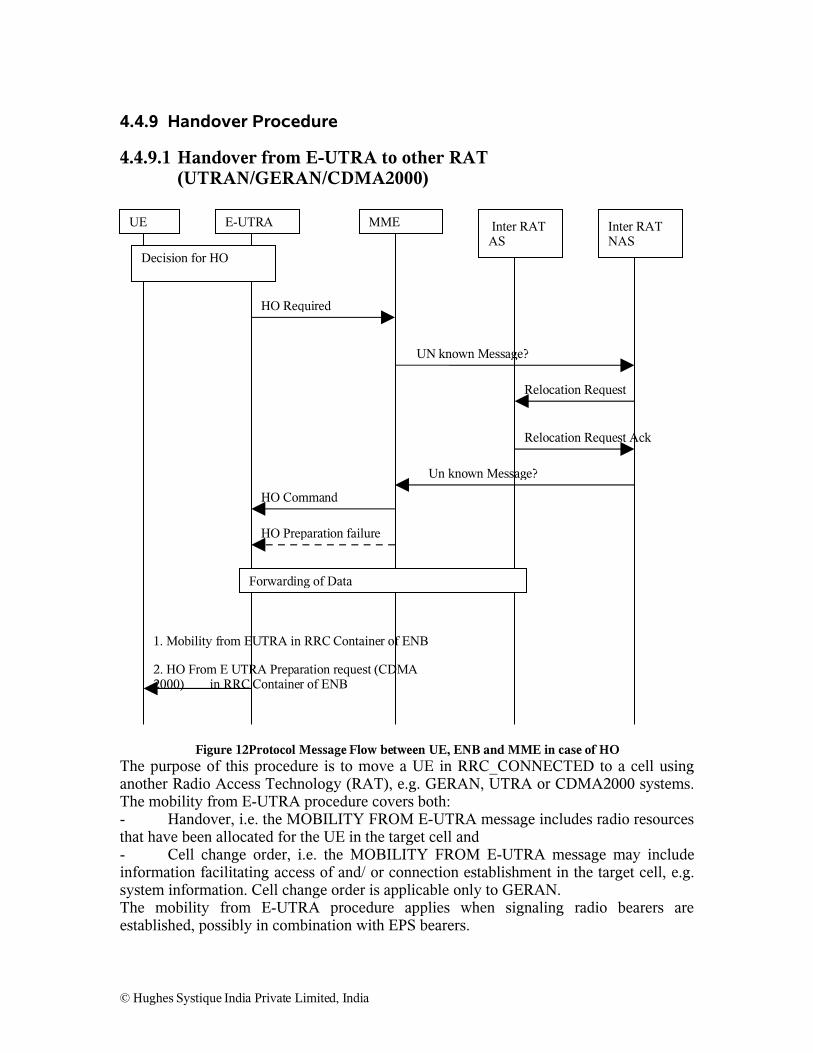
Figure 12Protocol Message Flow between UE, ENB and MME in case of HOThe purpose of this procedure is to move a UE in RRC_CONNECTED to a cell using another Radio Access Technology (RAT), e.g. GERAN, UTRA or CDMA2000 systems. The mobility from E-UTRA procedure covers both:- Handover, i.e. the MOBILITY FROM E-UTRA message includes radio resources that have been allocated for the UE in the target cell and- Cell change order, i.e. the MOBILITY FROM E-UTRA message may include information facilitating access of and/ or connection establishment in the target cell, e.g. system information. Cell change order is applicable only to GERAN.The mobility from E-UTRA procedure applies when signaling radio bearers are established, possibly in combination with EPS bearers.
© Hughes Systique India Private Limited, India
UE E-UTRA Inter RAT NAS
MME Inter RAT AS
Decision for HO
HO Required
UN known Message?
Relocation Request
Relocation Request Ack
Un known Message?
HO Command
HO Preparation failure
Forwarding of Data
1. Mobility from EUTRA in RRC Container of ENB
2. HO From E UTRA Preparation request (CDMA 2000) in RRC Container of ENB

4.4.9.2 Handover From other RAT (UTRAN/GERAN/CDMA2000) to E-UTRA
Figure 13 Protocol Message Flow between UE, ENB and MME in case of HO
The purpose of this procedure is to, under the control of the network; transfer a connection between the UE and another Radio Access Network (e.g. GERAN or UTRAN) to E-UTRAN. The handover to E-UTRA procedure applies when signaling radio bearers are established, possibly in combination with (EPS) bearers. In case only signaling radio bearers are established, it is FFS if the default EPS bearer is established during handover. It is FFS if handover to E-UTRAN may be initiated while security is not activated in the other RAT.
© Hughes Systique India Private Limited, India
UE E-UTRA Inter RAT NAS
MME Inter RAT AS
Decision for HO
Relocation Request
Un known Message ?
HO Request
HO Request Ack
Un known Message ?
Relocation Command
Forwarding of Data
RRC Connection Reconfiguration in RRC Container of other RAT
HO Failure
HO Notify
RRC Connection Reconfiguration Complete
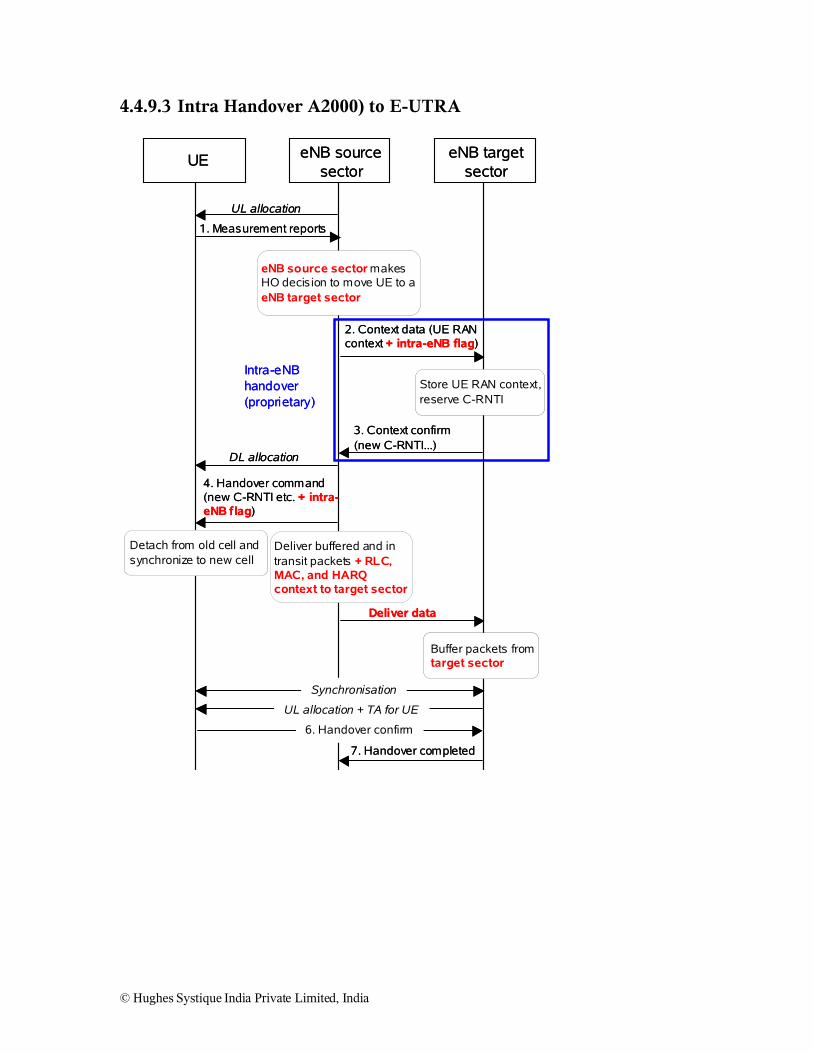
4.4.9.3 Intra Handover A2000) to E-UTRA
UE eNB source sector
eNB target sector
UL allocation
1. Measurement reports
eNB source sector makes HO decision to move UE to a eNB target sector
2. Context data (UE RAN context + intra-eNB flag)
Store UE RAN context, reserve C-RNTI
3. Context confirm (new C-RNTI...)
Deliver data
DL allocation
4. Handover command (new C-RNTI etc. + intra-eNB flag)
Detach from old cell and synchronize to new cell
Deliver buffered and in transit packets + RLC, MAC, and HARQ context to target sector
Buffer packets from target sector
Synchronisation
UL allocation + TA for UE
6. Handover confirm
7. Handover completed
Intra-eNB handover (proprietary)
© Hughes Systique India Private Limited, India