1900 Series Installation Guide
26
1900 Series Non-Contact Probes Installation Guide Your Guide to the 1900 Series Probes Entek IRD International Corporation P/N 45224
description
1900
Transcript of 1900 Series Installation Guide
1900 SeriesNon-Contact Probes
Installation Guide
Your Guide to the1900 Series Probes
Entek IRD International Corporation
P/N 45224
Copyright NoticeCopyright © 2000 by Entek IRD International Corporation
All Rights ReservedFirst Edition 2000Printed in the U.S.A.
This Manual is supplied to the User under license, subject to recall by Entek IRD International Corporation at any time, and the Manual at all times remains the property of Entek IRD International Corporation. The information contained in this Manual is considered confidential. No part of this Manual is to be copied or reproduced or transmitted in any form whatever (including orally or by electronic transmission), nor is any information in this Manual to be disclosed in any form whatever (including orally or by electronic transmission) to anyone other than an authorized representative of the User’s employer who also shall agree not to disclose same, without express prior written consent of Entek IRD International Corporation.
TrademarksEntek and IRD and registered trademarks of Entek IRD International Corporation.All other product names are registered trademarks of their respective owners.
Entek IRD International CorporationCorporate Headquarters1700 Edison DriveMilford, Ohio 45150
Contents
Entek IRD 1900 Series Non-Contact Probes Installation Guide iii
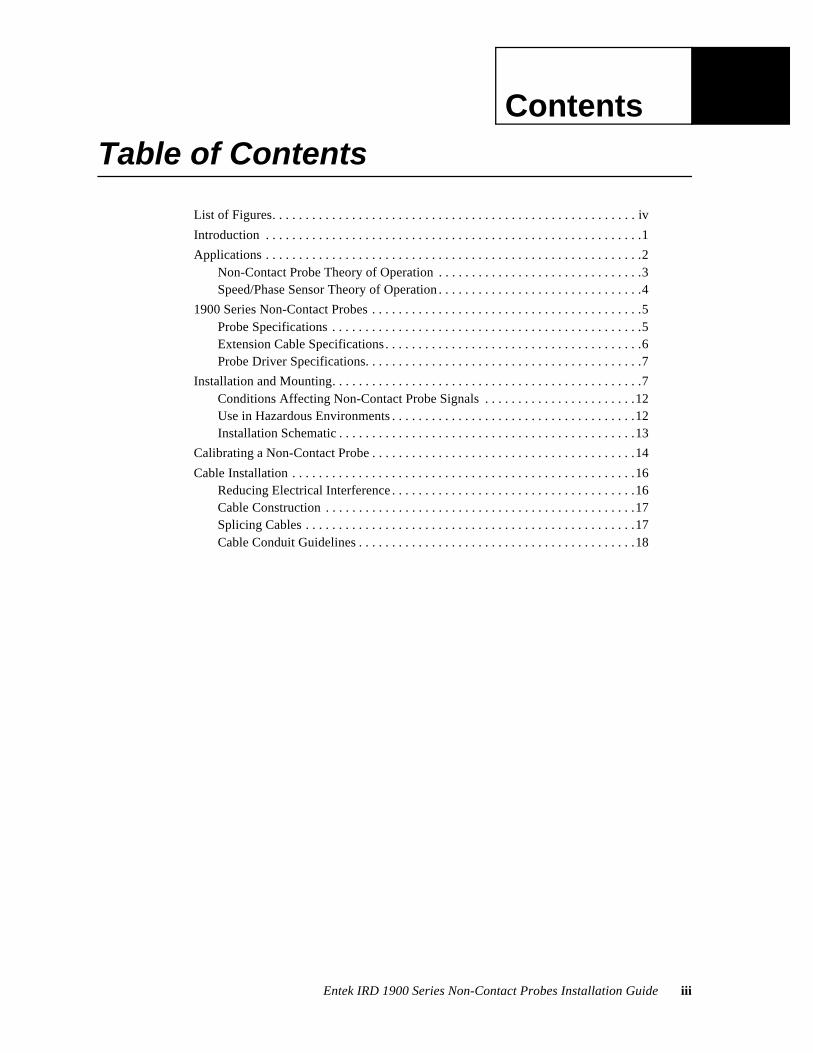
Table of Contents
List of Figures. . . . . . . . . . . . . . . . . . . . . . . . . . . . . . . . . . . . . . . . . . . . . . . . . . . . . . . iv
Introduction . . . . . . . . . . . . . . . . . . . . . . . . . . . . . . . . . . . . . . . . . . . . . . . . . . . . . . . . .1
Applications . . . . . . . . . . . . . . . . . . . . . . . . . . . . . . . . . . . . . . . . . . . . . . . . . . . . . . . . .2Non-Contact Probe Theory of Operation . . . . . . . . . . . . . . . . . . . . . . . . . . . . . . .3Speed/Phase Sensor Theory of Operation . . . . . . . . . . . . . . . . . . . . . . . . . . . . . . .4
1900 Series Non-Contact Probes . . . . . . . . . . . . . . . . . . . . . . . . . . . . . . . . . . . . . . . . .5Probe Specifications . . . . . . . . . . . . . . . . . . . . . . . . . . . . . . . . . . . . . . . . . . . . . . .5Extension Cable Specifications . . . . . . . . . . . . . . . . . . . . . . . . . . . . . . . . . . . . . . .6Probe Driver Specifications. . . . . . . . . . . . . . . . . . . . . . . . . . . . . . . . . . . . . . . . . .7
Installation and Mounting. . . . . . . . . . . . . . . . . . . . . . . . . . . . . . . . . . . . . . . . . . . . . . .7Conditions Affecting Non-Contact Probe Signals . . . . . . . . . . . . . . . . . . . . . . .12Use in Hazardous Environments . . . . . . . . . . . . . . . . . . . . . . . . . . . . . . . . . . . . .12Installation Schematic . . . . . . . . . . . . . . . . . . . . . . . . . . . . . . . . . . . . . . . . . . . . .13
Calibrating a Non-Contact Probe . . . . . . . . . . . . . . . . . . . . . . . . . . . . . . . . . . . . . . . .14
Cable Installation . . . . . . . . . . . . . . . . . . . . . . . . . . . . . . . . . . . . . . . . . . . . . . . . . . . .16Reducing Electrical Interference . . . . . . . . . . . . . . . . . . . . . . . . . . . . . . . . . . . . .16Cable Construction . . . . . . . . . . . . . . . . . . . . . . . . . . . . . . . . . . . . . . . . . . . . . . .17Splicing Cables . . . . . . . . . . . . . . . . . . . . . . . . . . . . . . . . . . . . . . . . . . . . . . . . . .17Cable Conduit Guidelines . . . . . . . . . . . . . . . . . . . . . . . . . . . . . . . . . . . . . . . . . .18
1.
iv Entek IRD gSE 2-Wire Transmitter Installation Guide
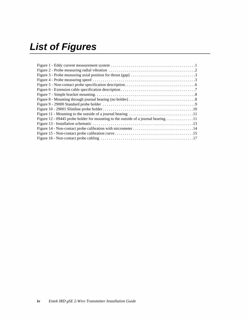
List of Figures
Figure 1 - Eddy current measurement system . . . . . . . . . . . . . . . . . . . . . . . . . . . . . . . . . . . . . . . . . .1Figure 2 - Probe measuring radial vibration . . . . . . . . . . . . . . . . . . . . . . . . . . . . . . . . . . . . . . . . . . .2Figure 3 - Probe measuring axial position for thrust (gap) . . . . . . . . . . . . . . . . . . . . . . . . . . . . . . . .3Figure 4 - Probe measuring speed . . . . . . . . . . . . . . . . . . . . . . . . . . . . . . . . . . . . . . . . . . . . . . . . . . .3Figure 5 - Non-contact probe specification description. . . . . . . . . . . . . . . . . . . . . . . . . . . . . . . . . . .6Figure 6 - Extension cable specification description . . . . . . . . . . . . . . . . . . . . . . . . . . . . . . . . . . . . .7Figure 7 - Simple bracket mounting. . . . . . . . . . . . . . . . . . . . . . . . . . . . . . . . . . . . . . . . . . . . . . . . . .8Figure 8 - Mounting through journal bearing (no holder) . . . . . . . . . . . . . . . . . . . . . . . . . . . . . . . . .8Figure 9 - 29000 Standard probe holder . . . . . . . . . . . . . . . . . . . . . . . . . . . . . . . . . . . . . . . . . . . . . .9Figure 10 - 29001 Slimline probe holder . . . . . . . . . . . . . . . . . . . . . . . . . . . . . . . . . . . . . . . . . . . . .10Figure 11 - Mounting to the outside of a journal bearing . . . . . . . . . . . . . . . . . . . . . . . . . . . . . . . .11Figure 12 - 09445 probe holder for mounting to the outside of a journal bearing. . . . . . . . . . . . . .11Figure 13 - Installation schematic . . . . . . . . . . . . . . . . . . . . . . . . . . . . . . . . . . . . . . . . . . . . . . . . . .13Figure 14 - Non-contact probe calibration with micrometer . . . . . . . . . . . . . . . . . . . . . . . . . . . . . .14Figure 15 - Non-contact probe calibration curve . . . . . . . . . . . . . . . . . . . . . . . . . . . . . . . . . . . . . . .15Figure 16 - Non-contact probe cabling . . . . . . . . . . . . . . . . . . . . . . . . . . . . . . . . . . . . . . . . . . . . . .17
Terms and Conditions
Entek IRD 1900 Series Non-Contact Probes Installation Guide v
ENTEK IRD INTERNATIONAL CORPORATION GENERAL TERMS AND CONDITIONS
1. CONTRACT. When Customer accepts a Quotation from Entek IRD International Corporation or an affiliate (the entity issuing the quotation being "Entek IRD") by issuance of a purchase order or otherwise and Entek IRD accepts the order, Customer is deemed to have agreed to all the Terms and Conditions contained herein. Unless otherwise approved in writing, the acceptance of Entek IRD is expressly conditioned upon Customer accepting these Terms and Conditions, and any different or additional terms and conditions contained in Customer's order or related documents are expressly objected to by Entek IRD and not binding upon it. Entek IRD reserves the right to accept or reject all orders received by it and all orders may only be accepted at the contracting office of Entek IRD located in Ohio. Entek IRD may accept in writing, by commencement of performance or otherwise.
2. QUOTATIONS. All quotations expire automatically thirty days from date of quotation or earlier by notice from Entek IRD. Unless otherwise noted in writing by Entek IRD, all prices are F.O.B. the place of origin for domestic shipments and Ex Works (as defined in INCOTERMS 1990) for international shipments; and risk of loss in transit is on Customer. Prices do not include any applicable taxes, however designated, levied or based upon the goods or services being quoted. Customer agrees to pay all such taxes or provide acceptable evidence of exemption therefrom.
3. TIMING. All delivery/shipping and service dates stated by Entek IRD are approximate dates only and estimated in good faith to the best of Entek IRD's ability and are dependent upon Entek IRD's prompt receipt of all necessary information from Customer. Time shall not be deemed to be of the essence in Entek IRD's performance of this agreement, and no penalty clause of any description in any specification or order will be effective unless specifically approved in writing by an authorized officer of Entek IRD. In any event delivery/shipping and service dates are always quoted subject to unavoidable delays due to causes beyond Entek IRD's control including but not limited to strikes, casualty, war, acts of God, systems failure or government action.
4. TERMS. Payment terms for domestic orders are net 10 days from date of invoice, unless otherwise provided in the quotation. For international orders, Entek IRD reserves the right to specify prepayment, letter of credit, or payment net 10 days from the date of invoice. Each shipment shall be considered a separate and independent transaction and payment must be made accordingly. If the financial condition or credit of Customer at any time in the judgment of Entek IRD, does not warrant shipment of goods ordered, Entek IRD may at its option require full payment prior to shipment or refuse to ship and terminate any order outstanding without liability to Entek IRD. If any sum is not paid by Customer when due, Entek IRD shall not be obligated to continue performance. If any amount is not paid when due, to the extent permitted by law a late fee of 1% per month (or any part thereof) shall be charged on past due amounts until paid.
5. CONFIDENTIALITY. If Customer data comes into Entek IRD's possession, Entek IRD shall use the same level of care to maintain the confidentiality of that data which Entek IRD uses for its own confidential information. Subject thereto, Entek IRD may use data in its possession to compile and maintain commercial machinery information databases in which the origin of specific data is not identifiable by users. Such databases shall be the sole property of Entek IRD.
6. CANCELLATION. Once accepted by Entek IRD, an order is not subject to cancellation in whole or in part by Customer without Entek IRD's prior written consent. Any such cancellation shall be subject to a cancellation charge as determined by Entek IRD to cover any loss that may be incurred by Entek IRD as a result of such cancellation, including without limitation a 25% restocking charge for standard products.
Terms and Conditions
vi Entek IRD 1900 Series Non-Contact Probes Installation Guide
7. CUSTOMER RESPONSIBILITIES. Customer shall be solely responsible for the accuracy and adequacy of the information provided to Entek IRD, and Entek IRD shall not be liable for any damages resulting from the loss, disclosure or inaccuracy of such information. Customer shall, for those contracts which include on-site installation, have the installation site prepared at its expense prior to the scheduled installation date to enable Entek IRD to promptly deliver and commence installation. The products are not for use in or with any nuclear facility, unless the Quotation expressly permits such use; and Customer shall indemnify and hold Entek IRD harmless from all liability (including such liability resulting from Entek IRD's negligence) arising out of such improper use. Customer shall not send or use the products outside the United States except in compliance with all applicable law, including U.S. export regulations and restrictions.
8. SOFTWARE AND SERVICES DOCUMENTS. If any computer software, whether incorporated into a piece of equipment ("firmware"),or provided separately, and related user documentation in any medium (collectively referred to as "Software") are included in the contract, the terms of the Entek IRD Standard Software License Agreement shall govern the contract with respect to Software. If any services other than oil analysis services are included in the contract, the Entek IRD Standard Field Engineering Services Terms and Conditions shall govern such services. Those documents are available to Customer upon request, and Customer is responsible to obtain and read the Standard Software License Agreement and the Standard Field Engineering Services Terms and Conditions.
9. LIMITED WARRANTIES AND REMEDIES. A. Entek IRD warrants to Customer (and not anyone else) that (i) all products manufactured by Entek IRD shall be free of defects in materials and workmanship under normal conditions for a period of one (1) year from the date of shipment (except that items with limited life such as batteries and lamps are warranted for 90 days from date of shipment) and that (ii) services will be free from defects in workmanship under normal conditions, for 90 days from performance. With respect to performance related in any way to the passage of time to the year 2000 and beyond, or the occurrence of a leap year, Entek IRD does not make any representation or warranty; Entek IRD has issued a Year 2000 readiness disclosure statement, which is available to Customer upon request.
B. With respect to any Entek IRD product or service that fails to satisfy the limited warranty provisions in this Section, as Customer's exclusive remedy, and at Entek IRD's option, Entek IRD will repair or replace the product or refund its purchase price or refund the purchase price of the service, provided that any defect is brought to the attention of Entek IRD within the warranty period. To qualify for this warranty concerning a product Customer must return the defective product to Entek IRD's designated facility freight prepaid, and after repair or replacement Entek IRD will return the product freight prepaid; or, if in Entek IRD's opinion the product is impractical to ship, Customer shall be charged for labor, transportation and subsistence expenses for the service representative(s) providing the warranty work at Customer's site. Entek IRD alone will be authorized to furnish or arrange for repairs or replacements.
C. The above limited warranties do not apply, and no warranty, either express or implied, shall be applicable, (a) to damage resulting from accident, alteration, misuse or abuse, harmful conditions, systems failure or Act of God; (b) if the product is not installed, operated and maintained according to procedures recommended by Entek IRD; or (c) if the Entek IRD serial number is obliterated. In no case shall the limited warranty extend to defects in materials, components, or services furnished by third parties or to the repair or installation of the product performed by third parties. The above warranties do not extend to any products sold "as-is" or "as-inspected;" no warranties, either express or implied, are made with respect to such products.
D. Entek IRD makes no representations or warranties to Customer, or anyone else, with respect to products manufactured by a third party. Any warranties of the third party manufacturers shall run directly to Customer to the extent permitted by law and Entek IRD shall have no liability therefor.
Terms and Conditions
Entek IRD 1900 Series Non-Contact Probes Installation Guide vii
E. The limited warranties in this Section constitute Entek IRD's entire warranty as to the products and services provided hereunder. ENTEK IRD HEREBY DISCLAIMS ALL OTHER WARRANTIES, EXPRESS OR IMPLIED, INCLUDING CONFORMITY TO ANY REPRESENTATION OR DESCRIPTION AND INCLUDING IMPLIED WARRANTIES OF MERCHANTABILITY AND FITNESS FOR ANY PARTICULAR PURPOSES WHATSOEVER.
10. EXCLUSIVE REMEDIES AND LIABILITY LIMITATION. THE REMEDIES PROVIDED HEREIN ARE CUSTOMER'S SOLE AND EXCLUSIVE REMEDIES, AND ENTEK IRD'S EXCLUSIVE LIABILITY WHETHER ARISING IN CONTRACT, TORT (INCLUDING NEGLIGENCE), STRICT LIABILITY OR ANY OTHER LEGAL THEORY. CUSTOMER AGREES THAT NO OTHER REMEDY (INCLUDING, BUT NOT LIMITED TO, INCIDENTAL OR CONSEQUENTIAL DAMAGES, LOST PROFITS, LOST SALES, LOST PRODUCTION, OVERHEAD, LABOR, INJURY TO PERSON OR PROPERTY, OR ANY OTHER INCIDENTAL LOSS) SHALL BE AVAILABLE TO CUSTOMER. THIS ALLOCATION OF RISK IS REFLECTED IN THE PRICES OF THE PRODUCTS AND SERVICES. ENTEK IRD'S MAXIMUM LIABILITY HEREUNDER ARISING FROM ANY CAUSE WHATSOEVER SHALL BE LIMITED TO THE PURCHASE PRICE OF THE PRODUCTS AND SERVICES IN QUESTION. Any suit related to this Agreement, on any legal theory, must be commenced within one year after the cause of action accrues.
11. TITLE AND LIEN RIGHTS. Each product shall remain personal property regardless of how it is affixed to Customer's real property and Entek IRD reserves a purchase money security interest in the product until the purchase price has been fully paid. Customer agrees to execute, and hereby appoints Entek IRD as its attorney-in-fact to execute on Customer's behalf, any documents requested by Entek IRD which are necessary for attachment and perfection of its security interest. If Customer defaults, Entek IRD shall have all the rights of a secured creditor under the Uniform Commercial Code as enacted in Ohio.
12. OTHER TERMS. These terms and conditions and any issue, claim or dispute arising hereunder shall be interpreted under and governed in all respects by the internal laws of the State of Ohio, and not by the 1980 U.N. Convention on the International Sale of Goods. These terms and conditions and the written quotation to which they relate constitute the entire contract between the parties, and supersede all other oral or written statements of any kind whatsoever made by the parties or their representatives. Waiver by Entek IRD of strict compliance with any one or more of these Terms and Conditions is not to be considered a continuing waiver or a waiver of any other term or condition. No statement purporting to modify any of these terms or conditions shall be binding unless expressly agreed to in writing signed by an officer of Entek IRD and by Customer.

Terms and Conditions
viii Entek IRD 1900 Series Non-Contact Probes Installation Guide
Entek IRD 1900 Series Non-Contact Probes Installation Guide 1
1900 Series
1. 1900 Series Non-Contact Probes
This manual shows you how to install the 1900 series non-contact eddy current probes. It is intended for anyone who installs or maintains a predictive maintenance system with permanently mounted non-contact probes.
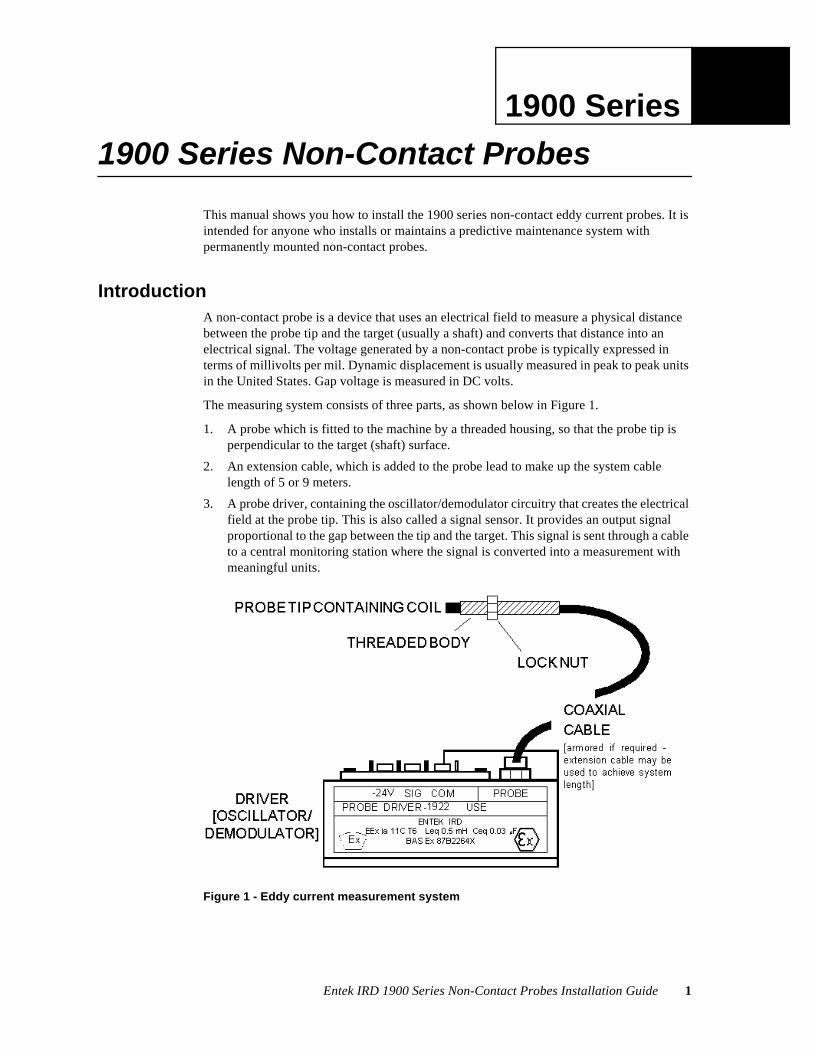
IntroductionA non-contact probe is a device that uses an electrical field to measure a physical distance between the probe tip and the target (usually a shaft) and converts that distance into an electrical signal. The voltage generated by a non-contact probe is typically expressed in terms of millivolts per mil. Dynamic displacement is usually measured in peak to peak units in the United States. Gap voltage is measured in DC volts.
The measuring system consists of three parts, as shown below in Figure 1.
1. A probe which is fitted to the machine by a threaded housing, so that the probe tip is perpendicular to the target (shaft) surface.
2. An extension cable, which is added to the probe lead to make up the system cable length of 5 or 9 meters.
3. A probe driver, containing the oscillator/demodulator circuitry that creates the electrical field at the probe tip. This is also called a signal sensor. It provides an output signal proportional to the gap between the tip and the target. This signal is sent through a cable to a central monitoring station where the signal is converted into a measurement with meaningful units.
Figure 1 - Eddy current measurement system
2 Entek IRD 1900 Series Non-Contact Probes Installation Guide
Applications
Together they form a tuned measurement circuit. In order for the non-contact probe to function correctly and accurately, several things must be true:
l It must be mounted correctly. Mounting options include using a threaded mounting bracket, installing the probe directly into the bearing housing, and using a probe holder attached to the machine.
l The measuring system (probe, extension cable, and driver) must be calibrated correctly.
l The target must have a uniform surface with no plating. It should be free of mechanical or electrical runout (variations in the smoothness or electrical properties of the surface). Per the requirements of API 670, section 4.1.1.2, we suggest the surface should be from 0.4 to 0.8 micormeters (16 to 32 microinches) RMS.
l The cable must be able to carry the signal without degrading the signal at the frequencies of interest over the length of the cable. The cable must be correctly connected to the monitoring device. In addition, proper grounding techniques must be observed at all times, and particularly when running the cable through a junction box.
This manual covers probes, monitoring systems, calibration, permanent mounting, and cable installation. Refer to the specific monitoring device manual for information about connecting the probe signal to the monitoring device.
Note: Non-contact probes can be damaged if dropped, or if the probe tip comes in contact with the moving shaft. Non-contact probes are calibrated as a system with the extension cable and driver, so replacing a probe or extension cable requires recalibrating the system. See “Calibrating a Non-Contact Probe” on page 14.
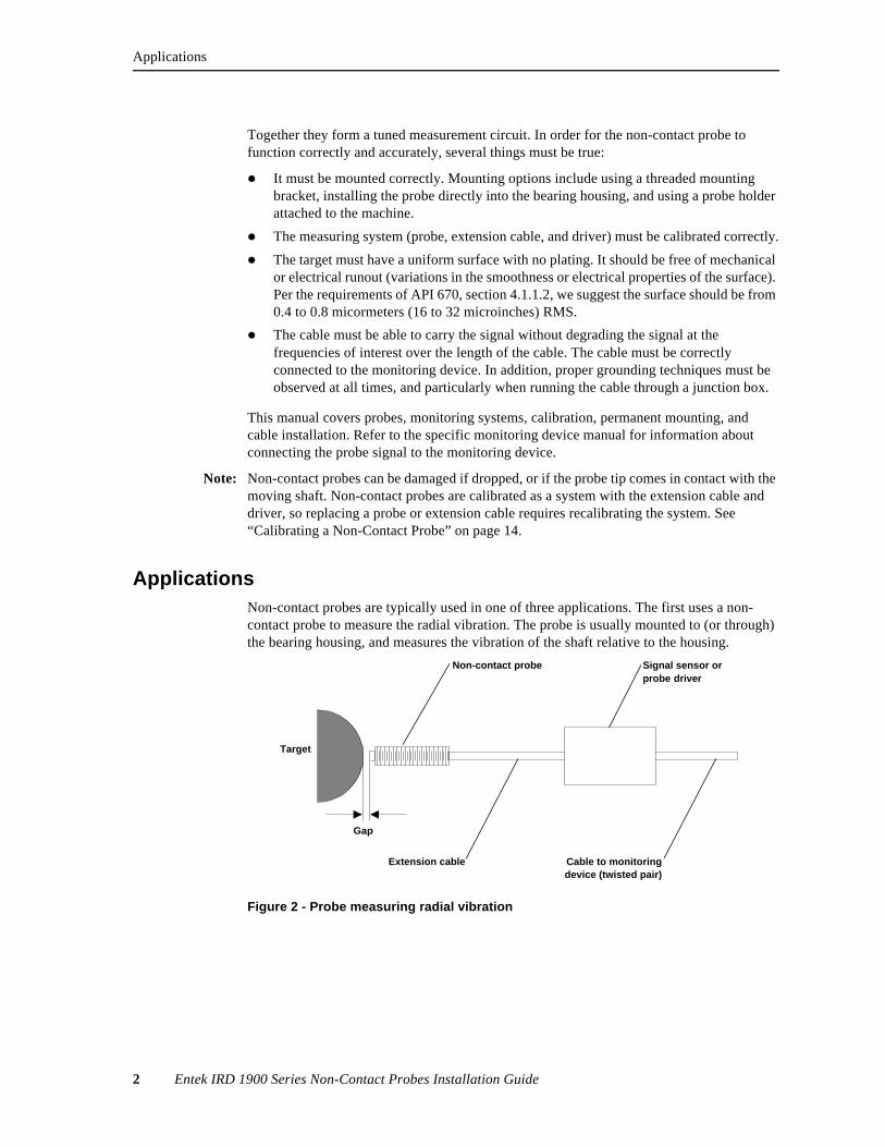
ApplicationsNon-contact probes are typically used in one of three applications. The first uses a non-contact probe to measure the radial vibration. The probe is usually mounted to (or through) the bearing housing, and measures the vibration of the shaft relative to the housing.
Signal sensor or probe driver
Gap
Cable to monitoringdevice (twisted pair)
Target
Non-contact probe
Extension cable
Figure 2 - Probe measuring radial vibration
Applications
Entek IRD 1900 Series Non-Contact Probes Installation Guide 3
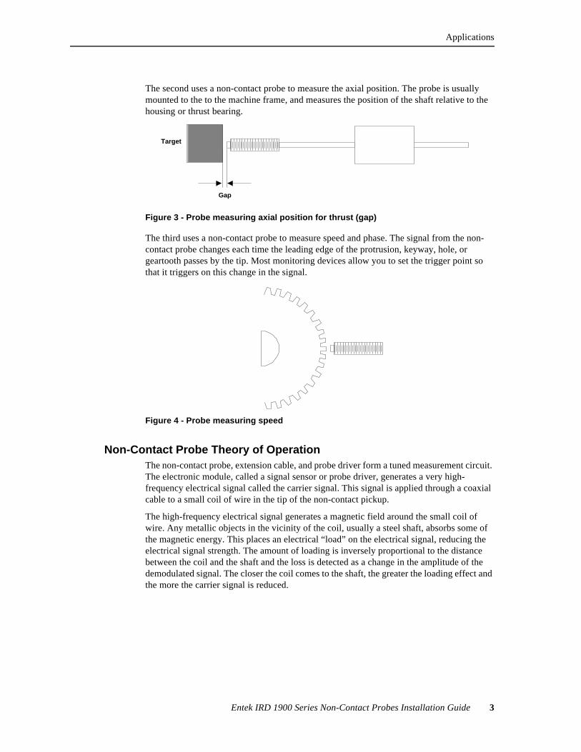
The second uses a non-contact probe to measure the axial position. The probe is usually mounted to the to the machine frame, and measures the position of the shaft relative to the housing or thrust bearing.
The third uses a non-contact probe to measure speed and phase. The signal from the non-contact probe changes each time the leading edge of the protrusion, keyway, hole, or geartooth passes by the tip. Most monitoring devices allow you to set the trigger point so that it triggers on this change in the signal.
Non-Contact Probe Theory of OperationThe non-contact probe, extension cable, and probe driver form a tuned measurement circuit. The electronic module, called a signal sensor or probe driver, generates a very high-frequency electrical signal called the carrier signal. This signal is applied through a coaxial cable to a small coil of wire in the tip of the non-contact pickup.
The high-frequency electrical signal generates a magnetic field around the small coil of wire. Any metallic objects in the vicinity of the coil, usually a steel shaft, absorbs some of the magnetic energy. This places an electrical “load” on the electrical signal, reducing the electrical signal strength. The amount of loading is inversely proportional to the distance between the coil and the shaft and the loss is detected as a change in the amplitude of the demodulated signal. The closer the coil comes to the shaft, the greater the loading effect and the more the carrier signal is reduced.
Gap
Target
Figure 3 - Probe measuring axial position for thrust (gap)
Figure 4 - Probe measuring speed

4 Entek IRD 1900 Series Non-Contact Probes Installation Guide
Applications
As the shaft moves relative to the tip of the probe, the strength of the electrical signal changes proportionally to the change in distance. The signal sensor provides an AC signal voltage proportional to the vibration and a DC signal proportional to the gap distance. The variation in the strength of the carrier signal is therefore proportional to the amount of vibration.
Speed/Phase Sensor Theory of OperationThe theory of operation for non-contact probes is described on page 3. The signal from the non-contact probe changes each time the leading edge of the protrusion, keyway, hole, or geartooth passes by the probe. Most monitoring devices allow you to set the trigger point so that it triggers on either a rising or a falling signal. Some monitoring devices also let you choose either the leading or trailing edge of the signal for the trigger. The illustration below shows the signal that results from a keyway.
The phase measurement calculated by the monitoring device depends on the device. There are multiple definitions for phase, two of which appear below:
l Vibration phase is defined as the phase angle between the 1x RPM (first order) vibration signal and the reference point on the shaft (the pulse from the non-contact probe).
l Absolute phase is defined as the phase angle between the reference point on the shaft and the first high (heavy) spot on the shaft.
Pickup coilMagnetic fieldin gap
Target
non-contact probe
0 VDC
Leading edge(falling signal)
Trailing edge
1900 Series Non-Contact Probes
Entek IRD 1900 Series Non-Contact Probes Installation Guide 5
Conditions affecting speed/phase sensor signalsThe conditions affecting the signals from non-contact probes are described on page 12.
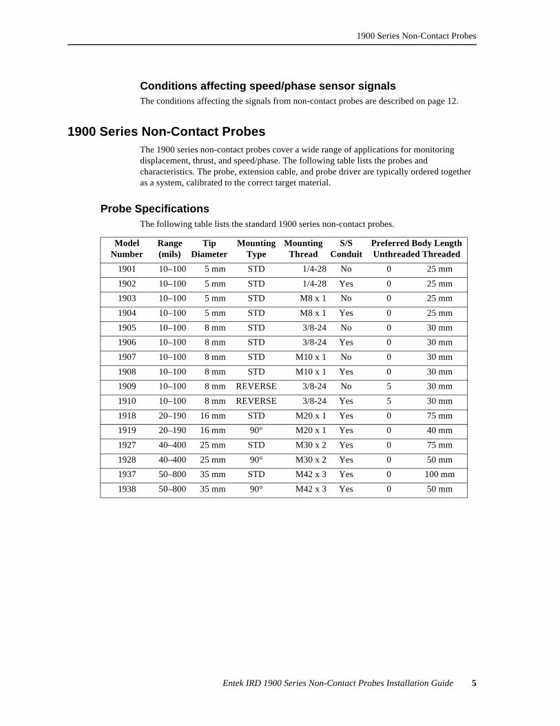
1900 Series Non-Contact ProbesThe 1900 series non-contact probes cover a wide range of applications for monitoring displacement, thrust, and speed/phase. The following table lists the probes and characteristics. The probe, extension cable, and probe driver are typically ordered together as a system, calibrated to the correct target material.
Probe SpecificationsThe following table lists the standard 1900 series non-contact probes.
ModelNumber
Range(mils)
TipDiameter
Mounting Type
Mounting Thread
S/S Conduit
Preferred Body LengthUnthreaded Threaded
1901 10–100 5 mm STD 1/4-28 No 0 25 mm
1902 10–100 5 mm STD 1/4-28 Yes 0 25 mm
1903 10–100 5 mm STD M8 x 1 No 0 25 mm
1904 10–100 5 mm STD M8 x 1 Yes 0 25 mm
1905 10–100 8 mm STD 3/8-24 No 0 30 mm
1906 10–100 8 mm STD 3/8-24 Yes 0 30 mm
1907 10–100 8 mm STD M10 x 1 No 0 30 mm
1908 10–100 8 mm STD M10 x 1 Yes 0 30 mm
1909 10–100 8 mm REVERSE 3/8-24 No 5 30 mm
1910 10–100 8 mm REVERSE 3/8-24 Yes 5 30 mm
1918 20–190 16 mm STD M20 x 1 Yes 0 75 mm
1919 20–190 16 mm 90° M20 x 1 Yes 0 40 mm
1927 40–400 25 mm STD M30 x 2 Yes 0 75 mm
1928 40–400 25 mm 90° M30 x 2 Yes 0 50 mm
1937 50–800 35 mm STD M42 x 3 Yes 0 100 mm
1938 50–800 35 mm 90° M42 x 3 Yes 0 50 mm

6 Entek IRD 1900 Series Non-Contact Probes Installation Guide
1900 Series Non-Contact Probes
The probe and integral cable is specified as shown in the following diagram.
The body thread is determined by the probe model number.
The probes are fitted with an insulating boot which mates with a matching boot on the extension cable. These should be pushed together to ensure electrical isolation of the connector body from the ground.
Extension Cable SpecificationsThe total length of the probe, integral cable, and extension cable should be 5 or 9 meters. This total length must also match the specification for the probe driver. The preferred lengths of extension cables are therefore 4.0, 4.5, 8.0, and 8.5 meters.
Probes and extension cables are not normally supplied with flexible stainless steel conduit as the cable has an internal stainless steel wire armoring. If flexible stainless steel conduit is preferred to standard rigid conduit on the machine, it can be specified. The preferred method of protecting cables, however, is to fit a permanent conduit system on the machine.
AA Body length in millimeters, in 5 mm multiples; see the table above for preferred standard lengths.
BB Unthreaded length in millimeters, in 5 mm multiples; see the table above for preferred standard lengths.
C 0 for no fitted connector, 1 for fitted connector
DD Total length of probe and integral cable; select total length to suit the required position of the connector in relation to the conduit arrangement on the machine. The preferred standards are 0.5 and 1.0 meters.
MODEL 1906 AA BB C DD
WITH CONNECTOR = 1WITHOUT CONNECTOR = 0
OVERALL LENGTH
UNTHREADED LENGTH
BODY LENGTH
Figure 5 - Non-contact probe specification description
Installation and Mounting
Entek IRD 1900 Series Non-Contact Probes Installation Guide 7
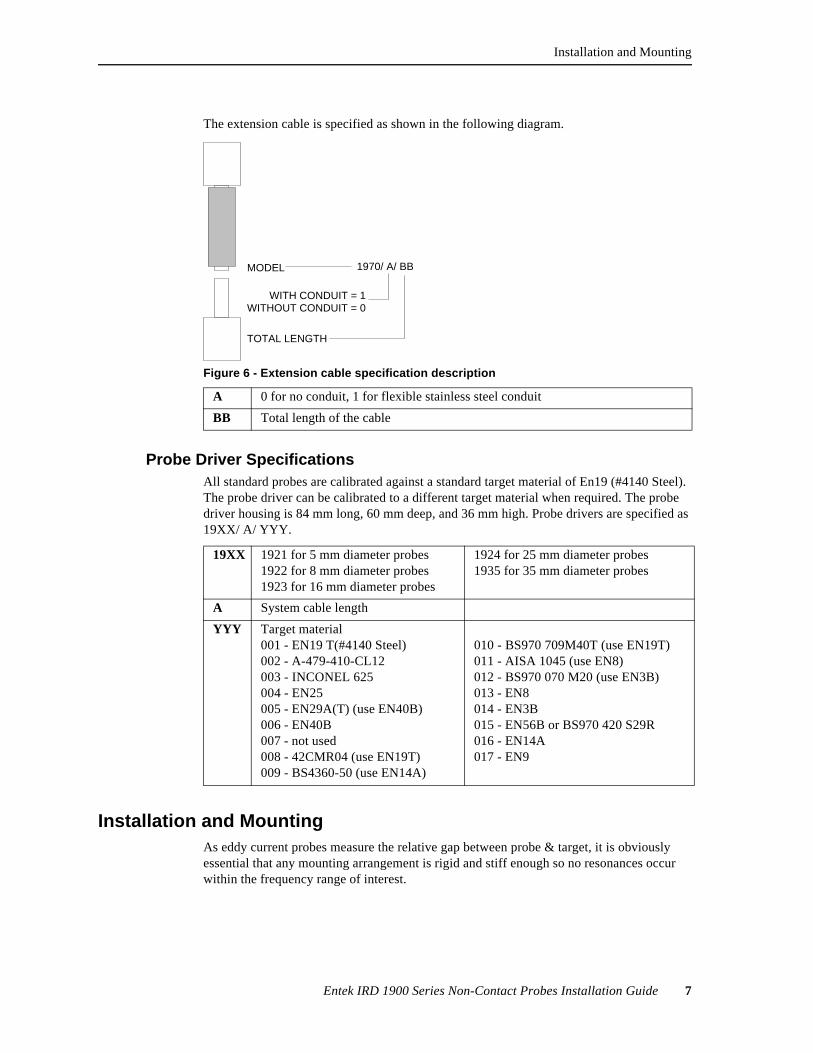
The extension cable is specified as shown in the following diagram.
Probe Driver SpecificationsAll standard probes are calibrated against a standard target material of En19 (#4140 Steel). The probe driver can be calibrated to a different target material when required. The probe driver housing is 84 mm long, 60 mm deep, and 36 mm high. Probe drivers are specified as 19XX/ A/ YYY.
Installation and MountingAs eddy current probes measure the relative gap between probe & target, it is obviously essential that any mounting arrangement is rigid and stiff enough so no resonances occur within the frequency range of interest.
A 0 for no conduit, 1 for flexible stainless steel conduit
BB Total length of the cable
MODEL 1970/ A/ BB
WITH CONDUIT = 1WITHOUT CONDUIT = 0
TOTAL LENGTH
Figure 6 - Extension cable specification description
19XX 1921 for 5 mm diameter probes1922 for 8 mm diameter probes1923 for 16 mm diameter probes
1924 for 25 mm diameter probes1935 for 35 mm diameter probes
A System cable length
YYY Target material001 - EN19 T(#4140 Steel)002 - A-479-410-CL12003 - INCONEL 625004 - EN25005 - EN29A(T) (use EN40B)006 - EN40B007 - not used008 - 42CMR04 (use EN19T)009 - BS4360-50 (use EN14A)
010 - BS970 709M40T (use EN19T)011 - AISA 1045 (use EN8)012 - BS970 070 M20 (use EN3B)013 - EN8014 - EN3B015 - EN56B or BS970 420 S29R016 - EN14A017 - EN9

8 Entek IRD 1900 Series Non-Contact Probes Installation Guide
Installation and Mounting
For most applications a simple bracket arrangement will usually suffice, (Figure 7, below).
The mounting plate shown is preferably threaded to accept the probe, as this facilitates easy, controlled adjustment. A locknut ensures that the desired setting is maintained. Alternatively probes may be located by a clearance hole and two locknuts or by an interference hole and split clamp housing. The spanner flats provided on the probe body should be used at all times and reasonable care exercised during installation to avoid damage to the probe tip. When using a threaded housing, disconnect the extension lead while adjusting, to avoid cable wind up and the imposition of a torque load on the assembly.
Make sure that the bracket itself does not introduce any extraneous vibrations. The free cantilevered length of each non-contact pickup holder must not exceed 20 centimeters. The bracket must not bend or flex. Even a small amount of flexing in the bracket may result in unreliable readings. Only a stiff bracket can support the probe without adding vibration due to the natural resonance frequency of the bracket. As a general rule, even the shortest bracket will require fabrication from 1/2-inch steel plate (at the minimum at least 9.4 millimeters thick).
All brackets should be tested for resonance in the frequencies that the probe will monitor. If possible, the bracket design should be approved by your transducer or system supplier.
The illustration below shows a non-contact probe mounted through the journal bearing. The probe measures radial vibration. Note that the tip clearance should be 1.5 times the tip diameter to each side of the probe tip. This means the total cutout should be 4 times the width of the probe tip.
Figure 7 - Simple bracket mounting
Note babbitt material cut away toavoid interference with transducer
eddy current field
Figure 8 - Mounting through journal bearing (no holder)
Installation and Mounting
Entek IRD 1900 Series Non-Contact Probes Installation Guide 9
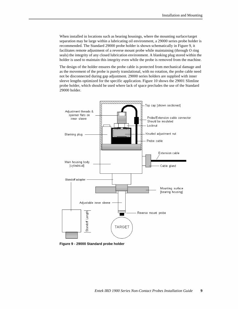
When installed in locations such as bearing housings, where the mounting surface/target separation may be large within a lubricating oil environment, a 29000 series probe holder is recommended. The Standard 29000 probe holder is shown schematically in Figure 9, it facilitates remote adjustment of a reverse mount probe while maintaining (through O ring seals) the integrity of any closed lubrication environment. A blanking plug stored within the holder is used to maintain this integrity even while the probe is removed from the machine.
The design of the holder ensures the probe cable is protected from mechanical damage and as the movement of the probe is purely translational, with no rotation, the probe cable need not be disconnected during gap adjustment. 29000 series holders are supplied with inner sleeve lengths optimized for the specific application. Figure 10 shows the 29001 Slimline probe holder, which should be used where lack of space precludes the use of the Standard 29000 holder.
Figure 9 - 29000 Standard probe holder
10 Entek IRD 1900 Series Non-Contact Probes Installation Guide
Installation and Mounting
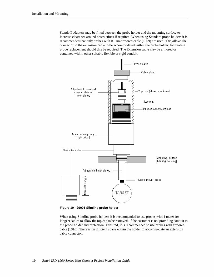
Standoff adapters may be fitted between the probe holder and the mounting surface to increase clearance around obstructions if required. When using Standard probe holders it is recommended that only probes with 0.5 un-armored cable (1909) are used. This allows the connector to the extension cable to be accommodated within the probe holder, facilitating probe replacement should this be required. The Extension cable may be armored or contained within other suitable flexible or rigid conduit.
When using Slimline probe holders it is recommended to use probes with 1 meter (or longer) cables to allow the top cap to be removed. If the customer is not providing conduit to the probe holder and protection is desired, it is recommended to use probes with armored cable (1910). There is insufficient space within the holder to accommodate an extension cable connector.
Figure 10 - 29001 Slimline probe holder
Installation and Mounting
Entek IRD 1900 Series Non-Contact Probes Installation Guide 11
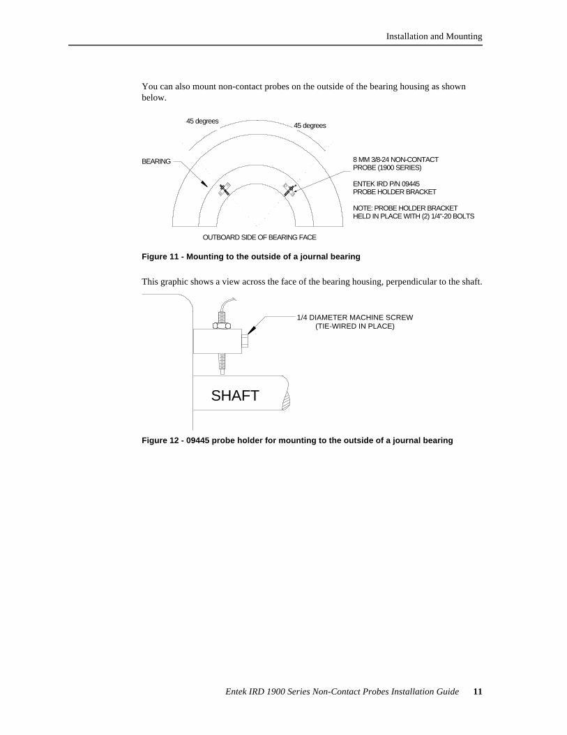
You can also mount non-contact probes on the outside of the bearing housing as shown below.
This graphic shows a view across the face of the bearing housing, perpendicular to the shaft.
BEARING
OUTBOARD SIDE OF BEARING FACE
8 MM 3/8-24 NON-CONTACTPROBE (1900 SERIES)
ENTEK IRD P/N 09445PROBE HOLDER BRACKET
NOTE: PROBE HOLDER BRACKETHELD IN PLACE WITH (2) 1/4"-20 BOLTS
45 degrees45 degrees
Figure 11 - Mounting to the outside of a journal bearing
1/4 DIAMETER MACHINE SCREW(TIE-WIRED IN PLACE)
SHAFT
Figure 12 - 09445 probe holder for mounting to the outside of a journal bearing
12 Entek IRD 1900 Series Non-Contact Probes Installation Guide
Installation and Mounting
Conditions Affecting Non-Contact Probe SignalsNon-contact probes should be calibrated after installation to determine the sensitivity. Calibrating the probe also verifies the linear range of the probe. This is usually done by using feeler gages to set the gap, then measuring the output signal. The calibration is also affected by the target material. The non-contact probe is usually calibrated to a known metal; for example SAE4140 steel.
The following conditions affect the accuracy of the non-contact probe signal:
l Target material if it is not the same as the metal used for factory calibration.
l Plating on the shaft should be removed in the target zone.
l Runout of the shaft in the target zone should be minimized. The runout can be mechanical (irregularities in the surface) or electrical. Per the requirements of API 670, section 4.1.1.2, we suggest the total runout should not exceed 25% of the maximum allowed peak-to-peak vibration, or 6 micrometers (0.25 mil).
l Surface smoothness of the target must be a uniform surface with no plating. Per the requirements of API 670, section 4.1.1.2, we suggest the surface should be from 0.4 to 0.8 micrometers (16 to 32 microinches) RMS.
l Extension cable length from the probe to the signal sensor (probe driver). The signal from a non-contact probe depends on the loading of the electrical signal from the signal sensor. The loading is affected by the cable from the probe to the signal sensor. If the probe is to be screwed into the mounting, disconnect the extension cable from the signal sensor to prevent twisting the extension cable.
l Electrical interference from a variety of sources can affect the signal from the non-contact probe.
Use in Hazardous EnvironmentsThe 1900 series probes are approved to EEx ia IIC T3 (to T6), under certificate number Ex 87B2265X, while the corresponding probe drivers are approved to EEx ia IIC T6 under certificate number Ex 87B2264X. They can therefore be used, with appropriate cabling and safety barriers, for measurements within hazardous areas. A system certification drawing showing the required arrangement is available if required. One polarized dual channel barrier, (typically MTL 796-) is required per transducer (note that the barrier channels are dissimilar).
It is a condition of approval that the electrical system within the hazardous area must be capable of withstanding a 500V test to earth, so clearly the insulation of cable connector and driver case should be carefully implemented. Driver housings supplied by Entek IRD are fitted, as standard, with isolating mounting bases.
Alternatively, galvanic isolators my be used. A system certification drawing showing the required arrangement is available if required. One Pepperl & Fuchs Transformer Isolated Voltage Repeater type KHD3-IVR/EX126 Certified by BASSEFA to EEx ia IIC is required per transducer.
Installation and Mounting
Entek IRD 1900 Series Non-Contact Probes Installation Guide 13
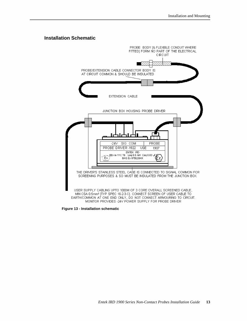
Installation Schematic
Figure 13 - Installation schematic
14 Entek IRD 1900 Series Non-Contact Probes Installation Guide
Calibrating a Non-Contact Probe
Calibrating a Non-Contact ProbeTwo points are worth noting regarding the calibration of eddy current probe systems.
1. The target material must be conductive, and indeed must be the only such material within the field emanating from the probe tip. This includes not only the area directly in front of the tip, but also to a radius of one tip diameter around it. If necessary the mounting surface must be counterbored or chamfered to achieve this clearance. The calibration of the system is affected by the resistivity of the target material and so the target material must be declared by the user before Entek IRD can supply a properly calibrated system. Unless otherwise requested, probe systems are calibrated against a 4140 steel target.
2. The most commonly used probes have 8mm diameter tips and are typically applied to the detection of shaft vibration in rotating machines. Such probes are usually installed such that the target surface is at the midpoint of their linear sensing range, in order that their actual working range is maximized. The linear range of a probe is determined by the coil geometry and is measured from the coil fitted within the probe tip. For the 8mm probe the midpoint of its range lies 0.050 inches (50 mil) from the coil. Calibrated to a standard sensitivity of -200mV/mil, this means that at a coil/target distance of 0.050 inches, the output from the probe driver system will be -10.0 volts. A physical measurement (using feeler gauges) would yield a tip to target gap of between 0.045 and 0.055 inch (45–55 mil).
A non-contact probe is calibrated as a system with its extension cable and signal sensor (probe driver) module. In addition, the calibration depends on the characteristics of the target material. There are two ways to calibrate a non-contact probe:
l If you can get a suitable piece of the target (shaft) material, you can calibrate the probe before installation.
l If you cannot get a piece of the target material, you can calibrate the probe after installation. Calibrating the probe after installation can be much more difficult, so if possible, calibrate the probe before installing it.
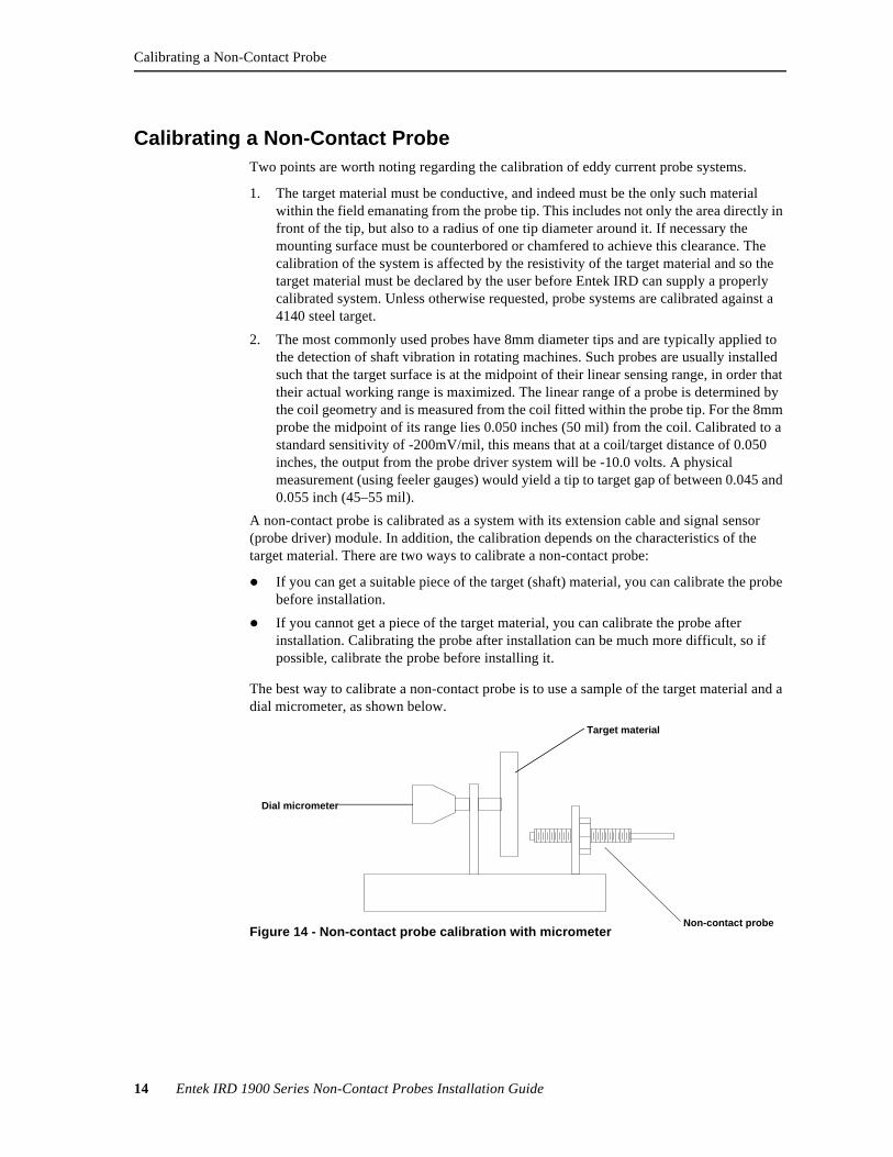
The best way to calibrate a non-contact probe is to use a sample of the target material and a dial micrometer, as shown below.
Dial micrometer
Non-contact probe
Target material
Figure 14 - Non-contact probe calibration with micrometer
Calibrating a Non-Contact Probe
Entek IRD 1900 Series Non-Contact Probes Installation Guide 15
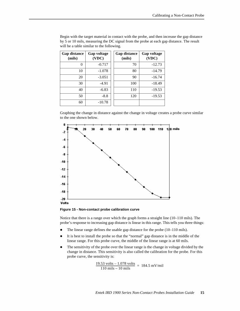
Begin with the target material in contact with the probe, and then increase the gap distance by 5 or 10 mils, measuring the DC signal from the probe at each gap distance. The result will be a table similar to the following.
Graphing the change in distance against the change in voltage creates a probe curve similar to the one shown below.
Notice that there is a range over which the graph forms a straight line (10–110 mils). The probe’s response to increasing gap distance is linear in this range. This tells you three things:
l The linear range defines the usable gap distance for the probe (10–110 mils).
l It is best to install the probe so that the “normal” gap distance is in the middle of the linear range. For this probe curve, the middle of the linear range is at 60 mils.
l The sensitivity of the probe over the linear range is the change in voltage divided by the change in distance. This sensitivity is also called the calibration for the probe. For this probe curve, the sensitivity is:
Gap distance (mils)
Gap voltage(VDC)
Gap distance (mils)
Gap voltage(VDC)
0 -0.717 70 -12.73
10 -1.078 80 -14.79
20 -3.051 90 -16.74
30 -4.91 100 -18.49
40 -6.83 110 -19.53
50 -8.8 120 -19.53
60 -10.78
Figure 15 - Non-contact probe calibration curve
19.53 volts 1.078 volts–110 mils 10 mils–
------------------------------------------------------------ 184.5 mV/mil=
16 Entek IRD 1900 Series Non-Contact Probes Installation Guide
Cable Installation
Cable InstallationThe cable from the probe is a critical component in getting the signal to the monitoring device. The 3-wire cables with shield listed below are dedicated, one per probe, to carry probe signals to the monitoring device.
Reducing Electrical InterferenceThe small electrical signal coming from a probe can be affected by electrical interference. Make every effort to reduce the electrical interference in cables to the lowest acceptable levels. Interference can come from many sources, including power cables, switching devices, motor controllers, walkie-talkies, robot transmitters, arc welders, induction heating equipment, motors, and high voltage ignition systems.
The following methods are effective for minimizing electrical interference:
l Use twisted pair wires in each cable.
l Use individual foil shields around each triplet, with a shield drain wire grounded at the monitoring divide for each shield. Non-contact probes are most often isolated at the machine end. Do not ground the shield at both ends of the cable. Grounding the cable shield at both ends causes a “ground loop.” This can cause interference because in most cases the ground potential differs at the two ends.
l Electrically isolate (insulate) each probe circuit from all others.
l Surround all cables with grounded steel conduit where possible.
l Do not use conduits containing probe cables for any other circuits.
l Avoid running 1900 probe cables parallel to other cables, such as other sensors, or communication cables.
l Avoid running probe cables parallel to power wiring. When this cannot be avoided, make sure that probe cables are at least 12 inches away from all power wiring carrying 120 V or less. For power circuits of 120–240 V, the minimum spacing is 24 inches. For circuits of 480 V or higher, the minimum spacing is 48 inches.
l If the cable must cross power wiring, maintain the above spacing between the wires. Cross the wires at a right angle (90°) to minimize interference.
l Make sure the cable is securely fastened to reduce low frequency noise from cable movement. This is particularly important at the cable from the probe to the probe driver.
No. of channels/ cable
Cable diam.
Belden No.
Max. Temp.
Alpha No.
Cable run up to 3400 feet
1 0.195 in4.95 mm
8771 140° F60° C
2403C
7 0.550 in14.0 mm
9771 176° F80° C
12 0.725 in18.4 mm
9772 176° F80° C
Cable Installation
Entek IRD 1900 Series Non-Contact Probes Installation Guide 17
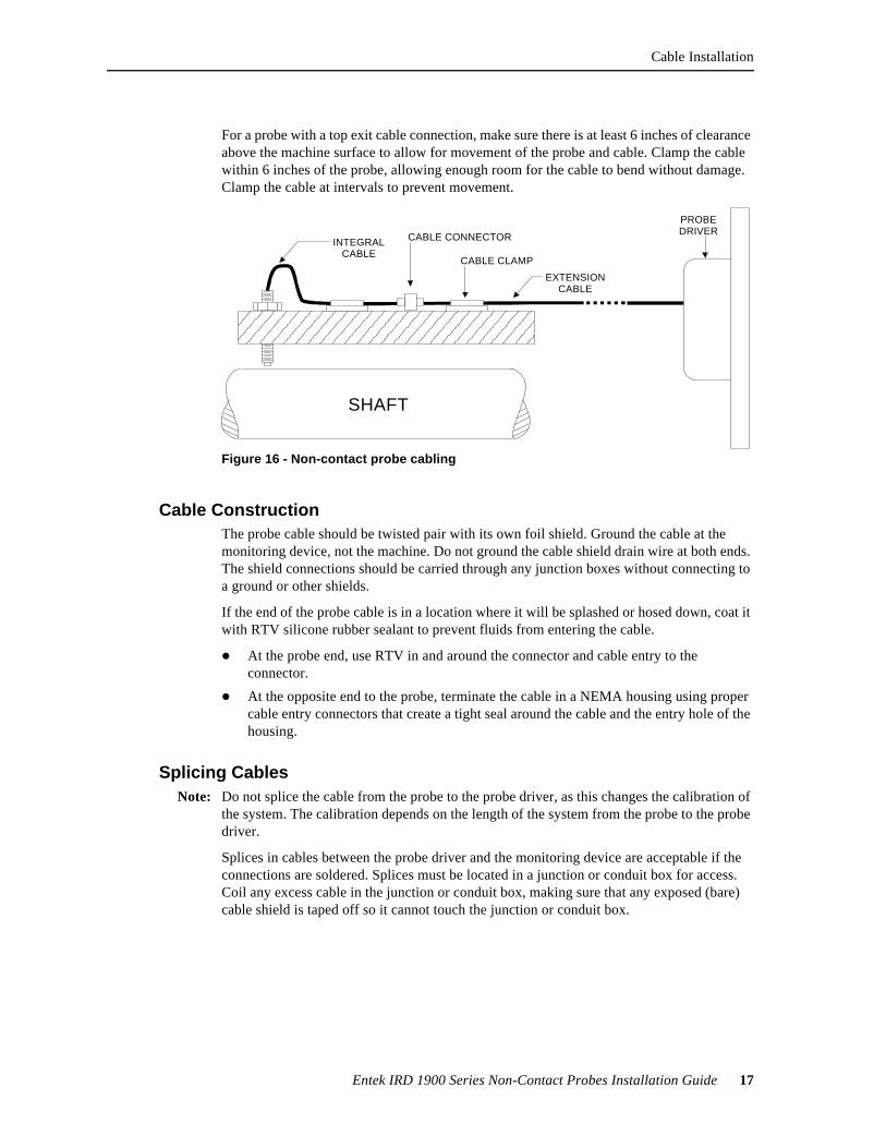
For a probe with a top exit cable connection, make sure there is at least 6 inches of clearance above the machine surface to allow for movement of the probe and cable. Clamp the cable within 6 inches of the probe, allowing enough room for the cable to bend without damage. Clamp the cable at intervals to prevent movement.
Cable ConstructionThe probe cable should be twisted pair with its own foil shield. Ground the cable at the monitoring device, not the machine. Do not ground the cable shield drain wire at both ends. The shield connections should be carried through any junction boxes without connecting to a ground or other shields.
If the end of the probe cable is in a location where it will be splashed or hosed down, coat it with RTV silicone rubber sealant to prevent fluids from entering the cable.
l At the probe end, use RTV in and around the connector and cable entry to the connector.
l At the opposite end to the probe, terminate the cable in a NEMA housing using proper cable entry connectors that create a tight seal around the cable and the entry hole of the housing.
Splicing CablesNote: Do not splice the cable from the probe to the probe driver, as this changes the calibration of
the system. The calibration depends on the length of the system from the probe to the probe driver.
Splices in cables between the probe driver and the monitoring device are acceptable if the connections are soldered. Splices must be located in a junction or conduit box for access. Coil any excess cable in the junction or conduit box, making sure that any exposed (bare) cable shield is taped off so it cannot touch the junction or conduit box.
SHAFT
CABLE CLAMP
INTEGRALCABLE
EXTENSIONCABLE
CABLE CONNECTOR
PROBE DRIVER
Figure 16 - Non-contact probe cabling
18 Entek IRD 1900 Series Non-Contact Probes Installation Guide
Cable Installation
Cable Conduit GuidelinesAll signal wiring should be run in grounded conduit, where it is protected from damage and external influences. The conduit must be installed with proper drain points so that water from condensation and other sources does not build up around the cable.
Cables in conduitWhen cables are run in steel conduit, the conduit must be grounded per NEC and local code requirements. Where necessary, flexible interlocked steel conduit can be used. Note that flexible conduit is not as effective against RF/EM interference as solid conduit. No wires or cables other than probe wires or cables should be run in the same conduit.
In high humidity areas, outdoors, or where the system may get wet, the conduit should be protected to prevent water from entering. If the conditions could cause condensation in the conduit, use rigid metallic conduit or liquid-tight flexible conduit with suitable fittings.
The “far” end of the conduit should be protected to prevent water from entering. Provide appropriate condensate drains at low points in the conduit runs to allow condensation to escape.
If a water-resistant seal is required, you can also use pipe joint sealing compound on fittings before screwing connectors to the probe body. Coat the terminal strip inside the junction box with RTV silicone rubber after the cables are connected. Do not use sealant on the gasket surfaces.
Conduit runs to panelsMake sure the conduits are large enough to accommodate the signal cables plus space for servicing. The maximum acceptable cable length from probe driver to monitoring device depends on the type of probe, the frequencies of interest, the grade of cable, and the monitoring device. Follow the manufacturer’s specifications for cable length and grade, or refer to the table under “Cable Installation” on page 16.
Conduit boxesUse a conduit or junction box to protect any connections or splices in the cable from the probe driver to the monitoring device.
l In wet areas, use NEMA-4X rated box. You can also use a 1/2 or 3/4-inch trade size conduit body with gasketed cover, mounted vertically to prevent water entry into the box.
l Locate the conduit box so that 1–2 inches of cable from the probe driver extends into the box.
l Use rigid thin wall or liquid-tight flexible conduit on the output cable.
l Ground the box and conduit to avoid electrical and radio frequency interference.