(19) TZZ Z T - patentimages.storage.googleapis.com · (73) Proprietor: Huawei Technologies Co.,...
41
Note: Within nine months of the publication of the mention of the grant of the European patent in the European Patent Bulletin, any person may give notice to the European Patent Office of opposition to that patent, in accordance with the Implementing Regulations. Notice of opposition shall not be deemed to have been filed until the opposition fee has been paid. (Art. 99(1) European Patent Convention). Printed by Jouve, 75001 PARIS (FR) (19) EP 2 280 567 B1 (Cont. next page) TEPZZ 8Z567B_T (11) EP 2 280 567 B1 (12) EUROPEAN PATENT SPECIFICATION (45) Date of publication and mention of the grant of the patent: 11.06.2014 Bulletin 2014/24 (21) Application number: 09734381.8 (22) Date of filing: 14.04.2009 (51) Int Cl.: H04W 72/04 (2009.01) (86) International application number: PCT/JP2009/057520 (87) International publication number: WO 2009/131037 (29.10.2009 Gazette 2009/44) (54) MOBILE STATION DEVICE, MOBILE COMMUNICATION SYSTEM, AND COMMUNICATION METHOD MOBILSTATIONSVORRICHTUNG, MOBILKOMMUNIKATIONSSYSTEM UND KOMMUNIKATIONSVERFAHREN DISPOSITIF DE STATION MOBILE, SYSTÈME DE COMMUNICATION MOBILE ET PROCÉDÉ DE COMMUNICATION (84) Designated Contracting States: AT BE BG CH CY CZ DE DK EE ES FI FR GB GR HR HU IE IS IT LI LT LU LV MC MK MT NL NO PL PT RO SE SI SK TR (30) Priority: 24.04.2008 JP 2008113788 (43) Date of publication of application: 02.02.2011 Bulletin 2011/05 (60) Divisional application: 14165161.2 (73) Proprietor: Huawei Technologies Co., Ltd. Shenzhen 518129 (CN) (72) Inventors: • YAMADA, Shohei c/o Sharp Kabushiki Kaisha Osaka 545-8522 (JP) • AIBA, Tatsushi c/o Sharp Kabushiki Kaisha Osaka 545-8522 (JP) (74) Representative: Körber, Martin Hans et al Mitscherlich PartmbB Patent- und Rechtsanwälte Postfach 33 06 09 80066 München (DE) (56) References cited: EP-A1- 2 131 622 • ERICSSON ET AL: "Control of semi persistent scheduling", 3GPP DRAFT; R2-080765 CONTROL OF SEMI PERSISTENT SCHEDULING, 3RD GENERATION PARTNERSHIP PROJECT (3GPP), MOBILE COMPETENCE CENTRE ; 650, ROUTE DES LUCIOLES ; F-06921 SOPHIA- ANTIPOLIS CEDEX ; FRANCE, vol. RAN WG2, no. Sorrento, Italy; 20080205, 5 February 2008 (2008-02-05), XP050138589, [retrieved on 2008-02-05] • MOTOROLA: "3GPP TSG RAN1#50 R1-073373 Search Space Definition for L1/L2 Control Channels", 3GPP TSG RAN1 #50, , vol. R1-073373, no. 50 20 August 2007 (2007-08-20), pages 1-11, XP002512720, Retrieved from the Internet: URL:http://www.3gpp.org/ftp/tsg_ ran/WG1_RL 1/TSGR1_50/Docs/R1-073373.zip [retrieved on 2009-01-29] • ERICSSON: ’PDCCH blind decoding - Outcome of offline discussions’ 3GPP TSG RAN WG1 #52, R1-081101, [Online] 11 February 2008, XP002534832 Retrieved from the Internet: <URL: http://www. 3gpp.org/ftp/tsg_ ran/WG1_RL1/TSGR1_52/Docs/ R1 -081101.zip> [retrieved on 2009-05-01] • ’3GPP TSG RAN WG1 Meeting #52bis, R1-081406, 2008.03.31’, 30 March 2008 article NTT DOCOMO: ’PDCCH Allocation Based on Hashing Function Generation Method for PDCCH Blind Decoding’, XP050109823 • 3GPP TS 36.300 V8.4.0 March 2008, pages 61 - 63, XP008134375
Transcript of (19) TZZ Z T - patentimages.storage.googleapis.com · (73) Proprietor: Huawei Technologies Co.,...

Note: Within nine months of the publication of the mention of the grant of the European patent in the European PatentBulletin, any person may give notice to the European Patent Office of opposition to that patent, in accordance with theImplementing Regulations. Notice of opposition shall not be deemed to have been filed until the opposition fee has beenpaid. (Art. 99(1) European Patent Convention).
Printed by Jouve, 75001 PARIS (FR)
(19)E
P2
280
567
B1
(Cont. next page)
TEPZZ 8Z567B_T(11) EP 2 280 567 B1
(12) EUROPEAN PATENT SPECIFICATION
(45) Date of publication and mention of the grant of the patent: 11.06.2014 Bulletin 2014/24
(21) Application number: 09734381.8
(22) Date of filing: 14.04.2009
(51) Int Cl.:H04W 72/04 (2009.01)
(86) International application number: PCT/JP2009/057520
(87) International publication number: WO 2009/131037 (29.10.2009 Gazette 2009/44)
(54) MOBILE STATION DEVICE, MOBILE COMMUNICATION SYSTEM, AND COMMUNICATION METHOD
MOBILSTATIONSVORRICHTUNG, MOBILKOMMUNIKATIONSSYSTEM UND KOMMUNIKATIONSVERFAHREN
DISPOSITIF DE STATION MOBILE, SYSTÈME DE COMMUNICATION MOBILE ET PROCÉDÉ DE COMMUNICATION
(84) Designated Contracting States: AT BE BG CH CY CZ DE DK EE ES FI FR GB GR HR HU IE IS IT LI LT LU LV MC MK MT NL NO PL PT RO SE SI SK TR
(30) Priority: 24.04.2008 JP 2008113788
(43) Date of publication of application: 02.02.2011 Bulletin 2011/05
(60) Divisional application: 14165161.2
(73) Proprietor: Huawei Technologies Co., Ltd.Shenzhen 518129 (CN)
(72) Inventors: • YAMADA, Shohei
c/o Sharp Kabushiki KaishaOsaka 545-8522 (JP)
• AIBA, Tatsushic/o Sharp Kabushiki KaishaOsaka 545-8522 (JP)
(74) Representative: Körber, Martin Hans et alMitscherlich PartmbB Patent- und Rechtsanwälte Postfach 33 06 0980066 München (DE)
(56) References cited: EP-A1- 2 131 622
• ERICSSON ET AL: "Control of semi persistent scheduling", 3GPP DRAFT; R2-080765 CONTROL OF SEMI PERSISTENT SCHEDULING, 3RD GENERATION PARTNERSHIP PROJECT (3GPP), MOBILE COMPETENCE CENTRE ; 650, ROUTE DES LUCIOLES ; F-06921 SOPHIA-ANTIPOLIS CEDEX ; FRANCE, vol. RAN WG2, no. Sorrento, Italy; 20080205, 5 February 2008 (2008-02-05), XP050138589, [retrieved on 2008-02-05]
• MOTOROLA: "3GPP TSG RAN1#50 R1-073373 Search Space Definition for L1/L2 Control Channels", 3GPP TSG RAN1 #50, , vol. R1-073373, no. 50 20 August 2007 (2007-08-20), pages 1-11, XP002512720, Retrieved from the Internet: URL:http://www.3gpp.org/ftp/tsg_ran/WG1_RL 1/TSGR1_50/Docs/R1-073373.zip [retrieved on 2009-01-29]
• ERICSSON: ’PDCCH blind decoding - Outcome of offline discussions’ 3GPP TSG RAN WG1 #52, R1-081101, [Online] 11 February 2008, XP002534832 Retrieved from the Internet: <URL:http://www. 3gpp.org/ftp/tsg_ran/WG1_RL1/TSGR1_52/Docs/ R1 -081101.zip> [retrieved on 2009-05-01]
• ’3GPP TSG RAN WG1 Meeting #52bis, R1-081406, 2008.03.31’, 30 March 2008 article NTT DOCOMO: ’PDCCH Allocation Based on Hashing Function Generation Method for PDCCH Blind Decoding’, XP050109823
• 3GPP TS 36.300 V8.4.0 March 2008, pages 61 - 63, XP008134375

2
EP 2 280 567 B1
• ALCATEL-LUCENT: ’Power Offsets to Support PUSCH Data and Control Multiplexing’ 3GPP TSG-RAN WG1 #52BIS, R1-081547, [Online] 31 March 2008, XP008134516 Retrieved from the Internet: <URL:http://www.3gpp.org/ftp/tsg_ran/WG1_RL 1/TSGR1_ 52b/Docs/R1-081547.zip> [retrieved on 2009-07-07]

EP 2 280 567 B1
3
5
10
15
20
25
30
35
40
45
50
55
Description
Technical Field
[0001] The present invention relates to a mobile stationapparatus, mobile communication system, communica-tion method and decoding processing of a physical down-link control channel.
Background Art
[0002] 3GPP (3rd Generation Partnership Project) is aproject for discussing and preparing specifications of cel-lular telephone systems based on networks of evolvedW-CDMA (Wideband-Code Division Multiple Access)and GSM (Global System for Mobile Communications).In 3GPP, the W-CDMA system has been standardizedas the 3rd-generation cellular mobile communicationsystem, and its service is started sequentially. Further,HSDPA (High-Speed Downlink Packet Access) with fur-ther increased communication rates has also been stand-ardized, and its service is started. 3GPP is discussingevolution of the 3rd-generation radio access technique(Evolved Universal Terrestrial Radio Access: hereinafter,referred to as "EUTRA").[0003] As a downlink communication system in EU-TRA, proposed is an OFDMA (Orthogonal Frequency Di-vision Multiple Access) system for multiplexing users us-ing mutually orthogonal subcarriers. Further, in the OFD-MA system are applied techniques such as an adaptivemodulation/demodulation-error correcting scheme(AMCS: Adaptive Modulation and Coding Scheme)based on adaptive radio link control (Link Adaptation)such as channel coding, etc. AMCS is a scheme forswitching between radio transmission parameters (here-inafter, referred to as an "AMC mode") such as an errorcorrecting scheme, coding rate of error correction, thelevel of data modulation, etc. corresponding to channelquality of each mobile station apparatus so as to efficient-ly perform high-speed packet data transmission. Thechannel quality of each mobile station apparatus is sentback to the base station apparatus using CQI (channelQuality indicator) as feedback.[0004] In OFDMA, it is possible to divide the commu-nicable region into the frequency domain physically cor-responding to subcarriers and time domain. A combina-tion of some divided regions is referred to as a resourceblock, one or more resource blocks are allocated to eachmobile station apparatus, and communications are per-formed while multiplexing a plurality of mobile station ap-paratuses. In order that the base station apparatus andeach mobile station apparatus perform communicationswith optimal quality and rate in response to the request,required is physical resource block allocation and trans-mission scheme determination with consideration givento the channel quality of a frequency band associatedwith each subcarrier in each mobile station apparatus.Since the base station apparatus determines the trans-
mission scheme and scheduling, to achieve the request,each mobile station apparatus gives feedback of channelquality for each frequency region to the base station ap-paratus. Further, when necessary, each mobile stationapparatus transmits information indicative of a frequencyregion (for example, with good channel quality) selectedby the mobile station apparatus to the base station ap-paratus as feedback.[0005] Further, in EUTRA, to increase communicationpath capacity, it has been proposed to use transmissiondiversity such as SDM (Space Division Multiplexing), SF-BC (Space-Frequency Block Diversity) and CDD (CycleDelay Diversity) using MIMO (Multiple Input Multiple Out-put). MIMO is a generic name for Multiple Input MultipleOutput systems or techniques, and is characterized inthat a plurality of branches is used in input and output ofradio signals to transmit, using a plurality of antennas onthe transmission and reception sides. A unit of a signalsequence is referred to as a stream that can be trans-mitted in space multiplexing using the MIMO scheme.The number (Rank) of streams in MIMO communicationsis determined by the base station apparatus in consider-ation of channel state. The number (Rank) of streamsrequested by the mobile station apparatus is sent to thebase station apparatus from the mobile station apparatusas feedback using RI (Rank Indicator).[0006] Meanwhile, in using SDM on downlink, in orderto accurately divide information of a plurality of streamstransmitted from respective antennas, it is under reviewto perform preprocessing on a transmission signal se-quence in advance (which is referred to as "precoding").The information of precoding can be calculated basedon channel state estimated by a mobile station appara-tus, and the mobile station apparatus gives feedback tothe base station apparatus using PMI (Precoding MatrixIndicator).[0007] Thus, in order to achieve communications ofoptimal quality, each mobile station apparatus is requiredto transmit various kinds of information indicative of chan-nel state to the base station apparatus as feedback. Thischannel feedback report CFR (channel state information)is formed of CQI, PMI, RI, etc. The number of bits andformat of these channel feedback reports are designatedfrom the base station apparatus to mobile station appa-ratuses corresponding to circumstances.[0008] FIG. 15 is a diagram illustrating a channel struc-ture in EUTRA (see Non-patent Document 1). The down-link of EUTRA is comprised of a physical broadcast chan-nel (PBCH), physical downlink control channel (PDCCH),physical downlink shared channel (PDSCH), physicalmulticast channel (PMCH), physical control format indi-cator channel (PCFICH), and physical Hybrid ARQ indi-cator channel (PHICH).[0009] Meanwhile, the uplink of EUTRA is comprisedof a physical uplink shared channel (PUSCH), physicalrandom access channel (PRACH), and physical uplinkcontrol channel (PUCCH).[0010] In EUTRA, due to the nature of uplink single
1 2

EP 2 280 567 B1
4
5
10
15
20
25
30
35
40
45
50
55
carrier, the mobile station apparatus cannot transmit sig-nals concurrently using different channels (for example,PUSCH and PUCCH). When the mobile station appara-tus transmits these channels at the same timing, the mo-bile station apparatus multiplexes the information usingthe definition of specifications, etc. to transmit on the de-termined channel, or transmits only either one of infor-mation according to the definition of specifications, etc.(does not transmit (drops) the other data).[0011] Meanwhile, the PUSCH is mainly used to trans-mit uplink data, and the channel feedback report CFR isalso transmitted using the PUSCH together with uplinkdata (UL-SCH) when the report is not transmitted usingthe PUCCH. In other words, the channel feedback reportCFR is transmitted to the base station apparatus usingthe PUSCH or PUCCH. Generally, within a subframe,the PUSCH is assigned greater resources allocated totransmit the channel feedback report CFR than in thePUCCH, and enables transmission of more detailedchannel feedback report CFR (when the number of phys-ical resource blocks supported by the base station ap-paratus and mobile station apparatus is 65 to 110 (systembandwidth of 20 MHz), information of about 20 to 100bits or more.) The mobile station apparatus can transmitinformation of only about 15 bits or less in a subframeusing the PUCCH.[0012] The mobile station apparatus is able to transmitthe channel feedback report CFR periodically using thePUCCH. Further, the mobile station apparatus is able totransmit the channel feedback report CFR periodically oraperiodically using the PUSCH (Non-patent Documents1 and 2). The base station apparatus sets persistent orpermanent resources and transmission interval of thePUSCH on a mobile station apparatus using RRC sign-aling (Radio Resource control signal), and enables themobile station apparatus to transmit the channel feed-back report CFR periodically using the PUSCH. Further,by including a single bit of information for instructions forchannel feedback report request (channel state reporttrigger) in an uplink transmission grant signal, the basestation apparatus enables the mobile station apparatusto transmit the channel feedback report CFR and uplinkdata aperiodically (temporarily, in one shot) using thePUSCH.[0013] Further, the mobile station apparatus is able totransmit only the channel feedback report CFR aperiod-ically using the PUSCH. Transmission of only the channelfeedback report CFR is that the mobile station apparatustransmits only the channel feedback report CFR to thebase station apparatus (where information ofACK/NACK, etc. is included), instead of concurrentlytransmitting the uplink data and channel feedback reportCFR.[0014] Meanwhile, in EUTRA, persistent or permanentPUSCH resources are scheduled for real-time trafficsuch as voice communications, and the mobile stationapparatus is capable of transmitting the PUSCH for up-link data without an uplink transmission grant signal by
PDCCH. This is called persistent scheduling. The basestation apparatus sets transmission intervals on the mo-bile station apparatus using RRC signaling (Radio Re-source Control signal), and activates persistent PUSCHallocation using a specific PDCCH. This specific PDCCHincludes information for specifying a persistent PUSCHresource block, modulation and coding scheme, etc.
Prior Art Document
Non-patent Document
[0015]
Non-patent Document 1: 3GPP TS (Technical Spec-ification) 36.300, v8.4.0 (2008-03), Technical Spec-ification Group Radio Access Network, Evolved Uni-versal Terrestrial Radio Access (E-UTRA) andEvolved Universal Terrestrial Radio Access Network(E-UTRAN); Overall description; Stage 2 (Release8)Non-patent Document 2: 3GPP TS (Technical Spec-ification) 36.213, V8. 2. 0 (2008-03), Technical Spec-ification Group Radio Access Network, physical Lay-er Procedures (Release 8)ERICSSON ET AL: "Control of semi persistentscheduling", 3GPP DRAFT R2-080765, discussesthe control of semi persistent scheduling. It is pro-posed that semi-persistent resources should be con-trolled via a separate C-RNTI (cell - radio networktemporary identity). The interpretation of thegrant/assignment received with this C-RNTI wouldbe configured to RRC (e.g. periodicity of thegrant/assignment). Explicit revoking of a semi-per-sistent grant can be handled by scheduling a trans-mission with the normal C-RNTI at a time point wheresemi-persistent transmission would occur or by al-locating a zero sized grant.MOTOROLA: "Search Space Definition for L1 /L2Control Channels", 3GPP DRAFT R1-073373, pro-poses a method of defining and mapping PDCCH(physical downlink control channel) search spacesfor different format as a function of carrier bandwidth,control region size, and the maximum number of con-trol channel elements allowed per search space. Mo-bile stations (UEs) can be primarily assigned to ap-propriate uplink and downlink search spaces by us-ing a hashing function, which is known at the mobilestation (UE) and the base station (eNB), based on aunique UE ID. The UE ID could be the C-RNTI,unique channel ID of assigned PUCCH, assignedsearch space ID (e.g. SP-RNTI) or other basis. Thenumber of blind detection is constrained to be lessthan 40 which means a maximum search space sizein control channel elements to be roughly 8.
3 4
EP 2 280 567 B1
5
5
10
15
20
25
30
35
40
45
50
55
Disclosure of Invention
Problems to be Solved by the Invention
[0016] However, in the conventional technique, therecoexist PUSCH persistent scheduling for uplink data andPUSCH persistent allocation for the periodic channelfeedback report CFR. Further, for signals required forthese instructions, since different signals are used de-spite the signals having a commonality, there is a problemthat the system design becomes complicated.[0017] Further, since different signals are used for amethod of starting periodic channel feedback and aperi-odic channel feedback, and a method of starting trans-mission of only channel feedback and concurrent trans-mission of channel feedback and uplink data, there is aproblem that it is not possible to efficiently switch there-between. Meanwhile, when an uplink transmission grantsignal in different format is newly introduced, anotherproblem occurs that unnecessary processing (blind de-coding processing) increases in mobile station appara-tuses.[0018] The present invention was made in view of suchcircumstances, and it is an object of the invention to pro-vide a mobile station apparatus, mobile communicationsystem and communication method for enabling a basestation apparatus to request a channel feedback reportand/or persistent scheduling to a mobile station appara-tus using an efficient signal.
Means for Solving the Problem
[0019]
(1) The above objects are solved by the claimed sub-ject matter according to the independent claims. Amobile station apparatus of the invention is a mobilestation apparatus for which an space of a physicaldownlink control channel to search is defined basedon a mobile station identity assigned from a basestation apparatus, and is characterized by perform-ing decoding processing of a physical downlink con-trol channel including a first mobile station identityand a physical downlink control channel including asecond mobile station identity in a search space ofa physical downlink control channel correspondingto the first mobile station identity when a plurality ofmobile station identities is assigned from the basestation apparatus.(2) Further, the mobile station apparatus of the in-vention is characterized in that the first mobile stationidentity is C-RNTI, and that the second mobile stationidentity is C-RNTI for persistent scheduling.(3) Moreover, a mobile communication system of theinvention is a mobile communication system in whichan space of a physical downlink control channel fora mobile station apparatus to search is definedbased on a mobile station identity assigned from a
base station apparatus, and is characterized in thatwhen the base station apparatus assigns a pluralityof mobile station identities to the mobile station ap-paratus, the base station apparatus places a physi-cal downlink control channel including a first mobilestation identity or a physical downlink control channelincluding a second mobile station identity in a searchspace of a physical downlink control channel corre-sponding to the first mobile station identity, and thatwhen a plurality of mobile station identities is as-signed from the base station apparatus, the mobilestation apparatus performs decoding processing ofthe physical downlink control channel including thefirst mobile station identity and the physical downlinkcontrol channel including the second mobile stationidentity in the search space of the physical downlinkcontrol channel corresponding to the first mobile sta-tion identity.(4) Further, the mobile communication system of theinvention is characterized in that the first mobile sta-tion identity is C-RNTI, and that the second mobilestation identity is C-RNTI for persistent scheduling.(5) Moreover, a mobile station apparatus of the in-vention is a mobile station apparatus for communi-cating with a base station apparatus, and is charac-terized by activating persistent resource allocationwhen a physical downlink control channel includesa particular mobile station identity, while deactivatingthe persistently allocated resources when the phys-ical downlink control channel includes the particularmobile station identity, and resource allocation infor-mation is a beforehand determined value.(6) Further, a mobile station apparatus of the inven-tion is a mobile station apparatus for communicatingwith a base station apparatus, and is characterizedby transmitting uplink data and a channel feedbackreport to the base station apparatus with persistentlyallocated uplink resources when a physical downlinkcontrol channel to allocate persistent resources in-cludes a request for the channel feedback report,while transmitting uplink data to the base station ap-paratus with persistently allocated uplink resourceswhen the physical downlink control channel does notinclude a request for the channel feedback report.(7) Moreover, a communication method of the inven-tion is a communication method in a mobile stationapparatus for which an space of a physical downlinkcontrol channel to search is defined based on a mo-bile station identity assigned from a base station ap-paratus, and is characterized in that the mobile sta-tion apparatus performs decoding processing of aphysical downlink control channel including a firstmobile station identity and a physical downlink con-trol channel including a second mobile station iden-tity in a search space of a physical downlink controlchannel corresponding to the first mobile stationidentity when a plurality of mobile station identitiesis assigned from the base station apparatus.
5 6
EP 2 280 567 B1
6
5
10
15
20
25
30
35
40
45
50
55
(8) Further, the communication method of the inven-tion is characterized in that the first mobile stationidentity is C-RNTI, and that the second mobile stationidentity is C-RNTI for persistent scheduling.(9) Moreover, a communication method of the inven-tion is a communication method in a mobile stationapparatus for communicating with a base station ap-paratus, and is characterized that the mobile stationapparatus activates persistent resource allocationwhen a physical downlink control channel includesa particular mobile station identity, while deactivatingthe persistently allocated resources when the phys-ical downlink control channel includes the particularmobile station identity, and resource allocation infor-mation is a beforehand determined value.(10) Further, a communication method of the inven-tion is a communication method in a mobile stationapparatus for communicating with a base station ap-paratus, and is characterized in that the mobile sta-tion apparatus transmits uplink data and a channelfeedback report to the base station apparatus withpersistently allocated uplink resources when a phys-ical downlink control channel to allocate persistentresources includes a request for the channel feed-back report, while transmitting uplink data to the basestation apparatus with persistently allocated uplinkresources when the physical downlink control chan-nel does not include a request for the channel feed-back report.
Advantageous Effect of the Invention
[0020] According to the invention, a mobile station ap-paratus selects either one of persistently allocated uplinkresources and temporarily allocated uplink resources asuplink resources to transmit a channel feedback reportbased on information included in a downlink control sig-nal, and is thereby capable of efficiently switching be-tween persistently and temporarily allocated uplink re-sources. As a result, the mobile station apparatus is ableto transmit a channel feedback report to the base stationapparatus using an efficient signal. Further, it is possibleto simplify the system design.
Brief Description of Drawings
[0021]
FIG. 1 is a diagram illustrating a structure of channelsin EUTRA;FIG. 2 is a diagram illustrating another structure ofchannels in EUTRA;FIG. 3 is a diagram illustrating a downlink framestructure in EUTRA;FIG. 4 is a diagram illustrating an uplink frame struc-ture in EUTRA;FIG. 5 is a block diagram illustrating a schematicstructure of a base station apparatus according to
Embodiments;FIG. 6 is a block diagram illustrating a schematicstructure of a mobile station apparatus according tothe Embodiments;FIG. 7 is a diagram showing an example of opera-tions of the mobile station apparatus correspondingto types of physical downlink control signals (PD-CCH);FIG. 8 is a diagram showing another example of op-erations of the mobile station apparatus correspond-ing to types of physical downlink control signals (PD-CCH);FIG. 9 is a diagram showing still another example ofoperations of the mobile station apparatus corre-sponding to types of physical downlink control sig-nals (PDCCH);FIG. 10 is a diagram showing an example of trans-mission/reception of signals between the mobile sta-tion apparatus and base station apparatus corre-sponding to dynamic physical downlink control sig-nals (PDCCH) shown in FIG. 7;FIG. 11 is a diagram showing an example of trans-mission/reception of signals between the mobile sta-tion apparatus and base station apparatus corre-sponding to the case where a channel feedback re-port dedicated request is designated by a persistent(or periodic channel feedback) physical downlinkcontrol signal (PDCCH) shown in FIG. 7;FIG. 12 is a diagram showing an example of trans-mission/reception of signals between the mobile sta-tion apparatus and base station apparatus corre-sponding to the case where a channel feedback re-port request is designated by a persistent (or periodicchannel feedback) physical downlink control signal(PDCCH) shown in FIG. 7;FIG. 13 is a diagram showing another example oftransmission/reception of signals between the mo-bile station apparatus and base station apparatuscorresponding to the case where a channel feedbackreport request is designated by a persistent (or pe-riodic channel feedback) physical downlink controlsignal (PDCCH) shown in FIG. 7;FIG. 14 is a diagram showing an example of trans-mission/reception of signals between the mobile sta-tion apparatus and base station apparatus corre-sponding to the case where a channel feedback re-port dedicated request is designated by a persistent(or periodic channel feedback) physical downlinkcontrol signal (PDCCH) shown in FIG. 7; andFIG. 15 is a diagram illustrating a channel structurein EUTRA.
Best Mode for Carrying Out the Invention
[0022] Embodiments according to the invention will bedescribed below with reference to drawings.
7 8
EP 2 280 567 B1
7
5
10
15
20
25
30
35
40
45
50
55
[channel structure]
[0023] FIGs. 1 and 2 are diagrams illustrating a chan-nel structure in EUTRA. As shown in FIGs. 1 and 2, thesechannels are classified into logical channels, transportchannels and physical channels. FIG. 1 shows downlinkchannels, and FIG. 2 shows uplink channels. The logicalchannels are to define types of data transmission servicetransmitted and received in a Medium Access control(MAC) layer. The transport channels are to define whatcharacteristics data transmitted in a radio interface hasand how the data is transmitted. The physical channelsare physical channels to convey the transport channels.[0024] Among the logical channels are included abroadcast control channel (BCCH), paging control chan-nel (PCCH), common control channel (CCCH), dedicat-ed control channel (DCCH), dedicated traffic channel(DTCH), multicast control channel (MCCH), and multi-cast traffic channel (MTCH).[0025] Among the transport channels are included abroadcast channel (BCH), paging channel (PCH), down-link shared channel (DL-SCH), multicast channel (MCH),uplink shared channel (UL-SCH), and random accesschannel (RACH).[0026] Among the physical channels are included aphysical broadcast channel (PBCH), physical downlinkcontrol channel (PDCCH), physical downlink sharedchannel (PDSCH), physical multicast channel (PMCH),physical uplink shared channel (PUSCH), physical ran-dom access channel (PRACH), physical uplink controlchannel (PUCCH), physical control format indicatorchannel (PCFICH), and physical Hybrid ARQ Indicatorchannel (PHICH). FIG. 15 shows the channels beingtransmitted and received.[0027] The logical channels will be described below.The broadcast control channel (BCCH) is a downlinkchannel used to broadcast system control information.The paging control channel (PCCH) is a downlink chan-nel used to transmit paging information, and is used whenthe network does not know the location cell of the mobilestation apparatus. The common control channel (CCCH)is a channel used to transmit control information betweenmobile station apparatuses and network, and is used bymobile station apparatuses having no radio resourcecontrol (RRC) connection with the network.[0028] The dedicated control channel (DCCH) is apoint-to-point bi-directional channel and is a channelused to transmit dedicated control information betweena mobile station apparatus and the network. The dedi-cated control channel (DCCH) is used by mobile stationapparatuses having an RRC connection. The dedicatedtraffic channel (DTCH) is a point-to-point bi-directionalchannel, dedicated to one mobile station apparatus, andused to transfer user information (unicast data).[0029] The multicast control channel (MCCH) is adownlink channel used to transmit MBMS control infor-mation from the network to mobile station apparatusesin a point-to-multipoint manner. This is used for Multime-
dia Broadcast Multicast Service (hereinafter referred toas "MBMS service") for offering point-to-multipoint serv-ice. Methods of transmitting MBMS service include Sin-gle-Cell Point-to-Multipoint (SCPTM) transmission andMultimedia Broadcast multicast service Single Frequen-cy Network (MBSFN) transmission. The MBSFN trans-mission is simultaneous transmission technique imple-mented by a plurality of cells simultaneously transmittingan identifiable waveform (signal). Meanwhile, theSCPTM transmission is a method where one base stationapparatus transmits MBMS service.[0030] The multicast control channel (MCCH) is adownlink channel used to transmit MBMS control infor-mation from the network to mobile station apparatusesin a point-to-multipoint manner. Further, the multicastcontrol channel (MCCH) is used for one or several mul-ticast traffic channels (MTCHs). The multicast trafficchannel (MTCH) is a downlink channel used to transmittraffic data (MBMS transmission data) from the networkto mobile station apparatuses in a point-to-multipointmanner. In addition, the multicast control channel(MCCH) and multicast traffic channel (MTCH) are onlyused by mobile station apparatuses that receive MBMS.[0031] The transport channels will be described below.The broadcast channel (BCH) needs to be broadcast tothe entire cell in fixed and pre-defined transmission for-mat. The downlink shared channel (DL-SCH) supportsHARQ, dynamic adaptive radio link control, discontinu-ous reception (DRX) and MBMS transmission, and needsto be broadcast to the enter cell. Further, the downlinkshared channel (DL-SCH) enables beam forming to beused, and supports dynamic resource allocation andsemi-static resource allocation. The paging channel(PCH) supports DRX and needs to be broadcast to theentire cell. Further, the paging channel is mapped tophysical resources which are used dynamically for thetraffic channel and other control channels, i.e. physicaldownlink shared channel (PDSCH).[0032] The multicast channel (MCH) needs to bebroadcast to the entire cell. Further, the multicast channel(MCH) supports MBSFN (MBMS Single Frequency Net-work) combining of MBMS transmission from a pluralityof cells, and semi-static resource allocation such as atime frame using a long cyclic prefix (CP). The uplinkshared channel (UL-SCH) supports HARQ and dynamicadaptive radio link control. Further, the uplink sharedchannel (UL-SCH) enables beam forming to be used,and supports dynamic resource allocation and semi-stat-ic resource allocation. The random access channel(RACH) is to transmit limited control information, and hasthe risk of collisions.[0033] The physical channels will be described next.The physical broadcast channel (PBCH) is to map thebroadcast channel (BCH) at 40 ms intervals. The 40 mstiming is blindly detected (blind detection) (in other words,explicit signaling is not performed to indicate the timing.)Each subframe including the physical broadcast channel(PBCH) can be decoded (self-decodable) from the sub-
9 10

EP 2 280 567 B1
8
5
10
15
20
25
30
35
40
45
50
55
frame, and is not divided into several times to transmit.[0034] The physical downlink control channel (PD-CCH) is used to inform the mobile station apparatusabout resource allocation of the downlink shared channel(PDSCH), hybrid automatic repeat request (HARQ) in-formation for downlink data, and uplink transmissiongrant (uplink grant) that is resource allocation of the phys-ical uplink shared channel (PUSCH).[0035] The physical downlink shared channel (PD-SCH) is a channel use to transmit downlink data or paginginformation. The physical multicast channel (PMCH) is achannel used to transmit the multicast channel (MCH),and additionally assigned a downlink reference signal,uplink reference signal and physical downlink synchro-nization signal.[0036] The physical uplink shared channel (PUSCH)is a channel mainly used to transmit uplink data (UL-SCH). When the base station apparatus performs sched-uling on the mobile station apparatus, the PUSCH is alsoused to transmit a channel feedback report (CQI, PMI,RI), and HARQ acknowledgement (ACK)/negative ac-knowledgement (NACK) in response to downlink trans-mission.[0037] The physical random access channel (PRACH)is a channel used to transmit a random access preamble,and has a guard time. The physical uplink control channel(PUCCH) is a channel used to transmit the channel feed-back report (CFR), scheduling request (SR), HARQ ac-knowledge (ACK)/negative acknowledgement (NACK) inresponse to downlink transmission, etc.[0038] The physical control format indicator channel(PCFICH) is a channel used to inform the mobile stationapparatus of the number of OFDM symbols used for thephysical downlink control channel (PDCCH), and trans-mitted in each subframe. The physical Hybrid ARQ indi-cator channel (PHICH) is used to transmit HARQACK/NACK in response to uplink transmission.
[Channel mapping]
[0039] As shown in FIG. 1, in the downlink, mappingis performed on the transport channels and physicalchannels as described below. The broadcast channel(BCH) is mapped on the physical broadcast channel(PBCH). The multicast channel (MCH) is mapped on thephysical multicast channel (PMCH). The paging channel(PCH) and downlink shared channel (DL-SCH) ismapped on the physical downlink shared channel (PD-SCH). The physical downlink control channel (PDCCH),physical hybrid ARQ indicator channel (PHICH) andphysical control format indicator channel (PCHICH) areused alone as a physical channel.[0040] Meanwhile, in the uplink, mapping is performedon the transport channels and physical channels as de-scribed below. The uplink shared channel (UL-SCH) ismapped on the physical uplink shared channel (PUSCH).The random access channel (RACH) is mapped on thephysical random access channel (PRACH). The physical
uplink control channel (PUCCH) is used alone as a phys-ical channel.[0041] Further, in the downlink, mapping is performedon the logical channels and transport channels as de-scribed below. The paging control channel (PCCH) ismapped on the downlink shared channel (DL-SCH). Thebroadcast control channel (BCCH) is mapped on thebroadcast channel (BCH) and downlink shared channel(DL-SCH). The common control channel (CCCH), dedi-cated control channel (DCCH) and dedicated traffic chan-nel (DTCH) are mapped on the downlink shared channel(DL-SCH). The multicast control channel (MCCH) ismapped on the downlink shared channel (DL-SCH) andmulticast channel[0042] (MCH). The multicast traffic channel (MTCH) ismapped on the downlink shared channel (DL-SCH) andmulticast channel (MCH).[0043] In addition, mapping of the multicast controlchannel (MCCH) and multicast traffic channel (MTCH)to the multicast channel (MCH) is performed in MBSFNtransmission, while this mapping is performed on thedownlink shared channel (DL-SCH) in SCPTM transmis-sion.[0044] Meanwhile, in the uplink, mapping is performedon the logical channels and transport channels as de-scribed below. The common control channel (CCCH),dedicated control channel (DCCH) and dedicated trafficchannel (DTCH) are mapped on the uplink shared chan-nel (UL-SCH). The random access channel (RACH) andlogical channels are not mapped.
[Radio frame structure]
[0045] A frame structure in EUTRA will be describedbelow. FIG. 3 illustrates a downlink frame structure, andFIG. 4 shows an uplink frame structure. A radio frameidentified by a system frame number (SFN) is constructedin 10 ms. A subframe is constructed in 1 ms, and oneradio frame contains 10 subframes.[0046] A single subframe is divided into two slots.When a normal CP is used, a downlink slot is comprisedof 7 OFDM symbols, and an uplink slot is comprised of7 SC-FDMA (Single Carrier-Frequency Division MultipleAccess) symbols. In addition, when a long CP (also re-ferred to as "extended CP") is used, a downlink slot iscomprised of 6 OFDM symbols, and an uplink slot is com-prised of 6 SC-FDMA symbols.[0047] Further, a single slot is divided into a pluralityof slots in the frequency direction. A single physical re-source block (PRB) is comprised of 12 subcarriers of 15KHz that are a unit in the frequency direction. As thenumber of physical resource blocks (PRB), 6 to 110blocks are supported corresponding to the system band-width. Downlink and uplink resource allocations are per-formed on a subframe basis in the time direction and ona physical resource block (PRB) basis in the frequencydirection. In other words, two slots within a subframe areallocated using a single resource allocation signal.
11 12

EP 2 280 567 B1
9
5
10
15
20
25
30
35
40
45
50
55
[0048] A unit comprised of a subcarrier and OFDMsymbol or a subcarrier and SC-FDMA symbol is referredto as a resource element. In resource mapping process-ing in the physical layer, a modulation symbol and thelike is mapped to each resource element.[0049] In the processing in the physical layer of thedownlink transport channel is performed addition of 24-bit cyclic redundancy check (CRC) to the physical down-link shared channel (PDSCH), channel coding (transmis-sion path coding), physical layer HARQ processing,channel interleaving, scrambling, modulation (QPSK,16QAM, 64QAM), layer mapping, precoding, resourcemapping, antenna mapping, etc. Meanwhile, in theprocessing in the physical layer of the uplink transportchannel is performed addition of 24-bit CRC to the phys-ical uplink shared channel (PUSCH), channel coding(transmission path coding), physical layer HARQprocessing, scrambling, modulation (QPSK, 16QAM,64QAM), resource mapping, antenna mapping, etc.[0050] The physical downlink control channel (PD-CCH), physical hybrid ARQ indicator channel (PHICH)and physical control format indicator channel (PCFICH)are placed within first three OFDM symbols. On the phys-ical downlink control channel (PDCCH) are transmittedtransport formats (specifying modulation scheme, codingscheme, transport block size, etc.) for the downlinkshared channel (DL-SCH), and paging channel (PCH),resource allocation, and HARQ information. Further, onthe physical downlink control channel (PDCCH) aretransmitted transport formats (specifying modulationscheme, coding scheme, transport block size, etc.) forthe uplink shared channel (UL-SCH), resource alloca-tion, and HARQ information. Moreover, a plurality ofphysical downlink control channels (PDCCHs) is sup-ported, and the mobile station apparatus monitors a setof physical downlink control channels (PDCCHs).[0051] The physical downlink shared channel (PD-SCH) assigned by the physical downlink control channel(PDCCH) is mapped to the same subframe as that of thephysical downlink control channel (PDCCH). The phys-ical uplink shared channel (PUSCH) assigned by thephysical downlink control channel (PDCCH) is mappedto a subframe in a beforehand determined position. Forexample, when the downlink subframe number on thephysical downlink control channel (PDCCH) is N, thephysical uplink shared channel (PUSCH) is mapped tothe N+4th uplink subframe.[0052] Further, in uplink/downlink resource allocationby the physical downlink control channel (PDCCH), themobile station apparatus is identified using 16-bit MAClayer identification information (MAC ID). In other words,this 16-bit MAC layer identification information (MAC ID)is included in the physical downlink control channel (PD-CCH).[0053] Furthermore, a downlink reference signal(downlink pilot channel) used for measurement of down-link conditions and demodulation of downlink data isplaced in the first and second OFDM symbols, and third
OFDM symbol from the last in each slot. Meanwhile, anuplink demodulation reference signal (demodulation pilot(DRS: Demodulation Reference Signal)) used for de-modulation of the physical uplink shared channel(PUSCH) is transmitted in the fourth SC-FDMA symbolin each slot. Further, an uplink measurement referencesignal (scheduling pilot (SRS: Sounding Reference Sig-nal)) used for measurement of uplink conditions is trans-mitted in the first SC-FDMA symbol of a subframe. Ademodulation reference signal of the uplink control chan-nel (PUCCH) is defined for each format of the uplink con-trol channel, and transmitted in the third, fourth and fifthSC-FDMA symbols in each slot, or the second and sixthSC-FDMA symbols in each slot.[0054] Moreover, the physical broadcast channel(PBCH) and downlink synchronization signal are placedin a band corresponding to six center physical resourceblocks in the system band. A physical downlink synchro-nization signal is transmitted in the sixth and seventhOFDM symbols in each slot of the first (subframe number#0) and fifth (subframe number #4) subframes. The phys-ical broadcast channel (PBCH) is transmitted in the fourthand fifth OFDM symbols of the first slot (slot #0) and inthe first and second OFDM symbols of the second slot(slot #1) in the first (subframe #0) subframe.[0055] Further, the random access channel (RACH) iscomprised of a bandwidth corresponding to six physicalresource blocks in the frequency direction and a singlesubframe in the time direction, and is transmitted for themobile station apparatus to make a request (request foruplink resources, request for uplink synchronization, re-quest for downlink data transmission resume, request forhandover, request for connection setting, request for re-connection, request for MBMS service, etc.) to the basestation apparatus for various reasons.[0056] The uplink control channel (PUCCH) is placedin opposite ends of the system band, and is comprisedof a unit physical resource block. Frequency hopping isperformed so that the opposite ends of the system bandare used alternately between slots.[0057] A communication system according to the Em-bodiments is comprised of a base station apparatus 100and mobile station apparatuses 200.
[Base station apparatus]
[0058] FIG. 5 is a block diagram illustrating a schematicstructure of a base station apparatus according to theEmbodiments. As shown in FIG. 5, the base station ap-paratus 100 is comprised of a data control section 101,OFDM modulation section 102, radio section 103, sched-uling section 104, channel estimation section 105, DFT-Spread-OFDM (DFT-S-OFDM) demodulation section106, data extraction section 107, and higher layer 108.Further, the radio section 103, scheduling section 104,channel estimation section 105, DFT-Spread-OFDM(DFT-S-OFDM) demodulation section 106, data extrac-tion section 107 and higher layer 108 constitute a receiv-
13 14
EP 2 280 567 B1
10
5
10
15
20
25
30
35
40
45
50
55
ing section, and the data control section 101, OFDMmod-ulation section 102, radio section 103 and schedulingsection 104 and higher layer 108 constitute a transmittingsection.[0059] The radio section 103, channel estimation sec-tion 105, DFT-Spread-OFDM (DFT-S-OFDM) demodu-lation section 106, and data extraction section 107 per-form the processing of the uplink physical layer. The radiosection 103, DFT-Spread-OFDM (DFT-S-OFDM) de-modulation section 106, and data extraction section 107perform the processing of the downlink physical layer.[0060] The data control section 101 receives the trans-port channel and scheduling information from the sched-uling section 104. The data control section 101 maps thetransport channel and signal and channel generated inthe physical layer on the physical channel based on thescheduling information input from the scheduling section104. Each data mapped as described above is output tothe OFDM modulation section 102.[0061] The OFDM modulation section 102 performsOFDM signal processing such as coding, data modula-tion, serial/parallel transform of an input signal, IFFT (In-verse Fast Fourier Transform) processing, CP (CyclicPrefix) insertion and filtering on the data input from thedata control section 101, based on the scheduling infor-mation (including downlink physical resource block(PRB) allocation information (for example, physical re-source block position information such as the frequencyand time), modulation scheme and coding scheme (suchas, for example, 16QAM, 2/3 coding rate, etc.) corre-sponding to each PRB, etc.) from the scheduling section104, and thereby generates an OFDM signal to outputto the radio section 103.[0062] The radio section 103 up-converts the modulat-ed data input from the OFDM modulation section 102into a signal with a radio frequency to generate a radiosignal, and transmits the radio signal to the mobile stationapparatus 200 via an antenna (not shown). Further, theradio section 103 receives an uplink radio signal from themobile station apparatus 200 via the antenna (notshown), down-coverts the radio signal into a basebandsignal, and outputs reception data to the channel estima-tion section 105 and DFT-S-OFDM demodulation section106.[0063] The scheduling section 104 performs theprocessing of the medium access control (MAC) layer.The scheduling section 104 performs mapping of the log-ical channels and transport channels, downlink and up-link scheduling (HARQ processing, selection of transportformat, etc.) and the like. In the downlink scheduling, thescheduling section 104 performs the processing for se-lecting a downlink transport format (transmission form)(physical resource block allocation, modulation schemeand coding scheme, etc.) to modulate each data, andretransmission control in HARQ, based on the uplinkfeedback information (downlink channel feedback infor-mation (channel state information (channel quality, thenumber of streams, pre-coding information, etc.),
ACK/NACK feedback information in response to down-link data, etc.) received from the mobile station apparatus200, the information of PRB usable in each mobile stationapparatus, buffer status, the scheduling information inputfrom the higher layer 108, etc. The scheduling informa-tion used in downlink scheduling is output to the datacontrol section 101.[0064] Further, in the uplink scheduling, the schedulingsection 104 performs the processing for selecting an up-link transport format (transmission form) (physical re-source block allocation, modulation scheme and codingscheme, etc.) to modulate each data, based on an esti-mation result of channel state (radio propagation pathconditions) on uplink output from the channel estimationsection 105, resource allocation request from the mobilestation apparatus 200, information of PRB usable in eachmobile station 200, the scheduling information input fromthe higher layer 108, etc. The scheduling informationused in uplink scheduling is output to the data controlsection 101.[0065] Furthermore, the scheduling section 104 mapsthe downlink logical channel input from the higher layer108 on the transport channel to output to the data controlsection 101. Moreover, the scheduling section 104 per-forms processing on the control data and transport chan-nel that is acquired on uplink and input from the dataextraction section 107 when necessary, and then, mapsthe resultant on the uplink logical channel to output tothe higher layer 108.[0066] The channel estimation section 105 estimatesuplink channel state from an uplink demodulation refer-ence signal (DRS) to demodulate uplink data, and out-puts the estimation result to the DFT-S-OFDM demodu-lation section 106. Further, in order to perform uplinkscheduling, the channel estimation section 105 esti-mates uplink channel state from an uplink measurementreference signal (SRS: Sounding Reference Signal), andoutputs the estimation result to the scheduling section104. In addition, as an uplink communication scheme, asingle-carrier scheme is assumed such as DFT-S-OFDM, etc, but a multicarrier scheme may be used suchas an OFDM scheme.[0067] The DFT-S-OFDM demodulation section 106performs DFT-S-OFDM signal processing such as DFTtransform, subcarrier mapping, IFFT transform, filtering,etc. on modulated data input from the radio section 103based on the uplink channel state estimation result inputfrom the channel estimation section 105, and performsdemodulation processing on the resultant to output to thedata extraction section 107.[0068] The data extraction section 107 checks the datainput from the DFT-S-OFDM demodulation section 106for accuracy or error, and outputs the checking result(acknowledge signal ACK/negative acknowledge signalNACK) to the scheduling section 104. Further, the dataextraction section 107 divides the data input from theDFT-S-OFDM demodulation section 106 into the trans-port channel and control data of the physical layer to out-
15 16

EP 2 280 567 B1
11
5
10
15
20
25
30
35
40
45
50
55
put to the scheduling section 104. The divided controldata includes the feedback information on uplink (down-link channel feedback report CFR, and ACK/NACK feed-back information in response to the downlink data) andthe like.[0069] The higher layer 108 performs the processingin the packet data convergence protocol (PDCP) layer,radio link control (RLC) layer, and radio resource control(RRC) layer. The higher layer 108 has a radio resourcecontrol section 109 (also referred to as a control section).The radio resource control section 109 performs man-agement of various kinds of setting information, manage-ment of system information, paging control, managementof communication conditions of each mobile station ap-paratus, moving management such as handover, man-agement of buffer status for each mobile station appara-tus, management of connection settings of unicast andmulticast bearers, management of mobile station identi-ties (UEID), etc.
[Mobile station apparatus]
[0070] FIG. 6 is a block diagram illustrating a schematicstructure of the mobile station apparatus according to theEmbodiments. As shown in FIG. 6, the mobile stationapparatus 200 is comprised of a data control section 201,DFT-S-OFDM modulation section 202, radio section 203,scheduling section 204, channel estimation section 205,OFDM demodulation section 206, data extraction section207, and higher layer 208. Further, the data control sec-tion 201, DFT-S-OFDM modulation section 202, radiosection 203, scheduling section 204 and higher layer 208constitute a transmitting section, and the radio section203, scheduling section 204, channel estimation section205, OFDM demodulation section 206, data extractionsection 207 and higher layer 208 constitute a receivingsection. Further, the scheduling section 204 constitutesa selecting section.[0071] The data control section 201, DFT-S-OFDMmodulation section 202 and radio section 203 performthe processing of the uplink physical layer. The radio sec-tion 203, channel estimation section 205, OFDM demod-ulation section 206 and data extraction section 207 per-form the processing of the downlink physical layer.[0072] The data control section 201 receives the trans-port channel and scheduling information from the sched-uling section 204. The data control section 201 maps thetransport channel and signal and channel generated inthe physical layer on the physical channel based on thescheduling information input from the scheduling section204. Each data mapped as described above is output tothe DFT-S-OFDM modulation section 202.[0073] The DFT-S-OFDM modulation section 202 per-forms DFT-S-OFDM signal processing such as datamodulation, DFT (Discrete Fourier Transform) process-ing, subcarrier mapping, IFFT (Inverse Fast FourierTransform) processing, CP insertion, filtering, etc. on thedata input from the data control section 201, and thereby
generates a DFT-S-OFDM signal to output to the radiosection 203.[0074] In addition, as an uplink communicationscheme, a single-carrier scheme is assumed such asDFT-S-OFDM, etc, but may be substituted by a multicar-rier scheme such as an OFDM scheme to be used.[0075] The radio section 203 up-converts the modulat-ed data input from the DFT-S-OFDM modulation section202 into a signal with a radio frequency to generate aradio signal, and transmits the radio signal to the basestation apparatus 100 via an antenna (not shown).[0076] Further, the radio section 203 receives a radiosignal modulated with the downlink data from the basestation apparatus 100 via the antenna (not shown), down-coverts the radio signal into a baseband signal, and out-puts reception data to the channel estimation section 205and OFDM demodulation section 206.[0077] The scheduling section 204 performs theprocessing of the medium access control (MAC) layer.The scheduling section 204 performs mapping of the log-ical channels and transport channels and downlink anduplink scheduling (HARQ processing, selection of trans-port format, etc.). In the downlink scheduling, the sched-uling section 204 performs reception control of the trans-port channel, physical signal and physical channel andHARQ retransmission control based on the schedulinginformation (transport format and HARQ retransmissioninformation) and the like from the base station apparatus100 and higher layer 208.[0078] In the uplink scheduling, the scheduling section204 performs scheduling processing for mapping the up-link logical channel input from the higher layer 208 onthe transport channel based on the uplink buffer statusinput from the higher layer 208, uplink scheduling infor-mation (transport format, HARQ retransmission informa-tion, etc.) from the base station apparatus 100 input fromthe data extraction section 207, and the scheduling in-formation input from the higher layer 208. In addition, forthe uplink transport format, the information notified fromthe base station apparatus 100 is used. These kinds ofscheduling information are output to the data control sec-tion 201.[0079] Further, the scheduling section 204 maps theuplink logical channel input from the higher layer 208 onthe transport channel to output to the data control section201. Furthermore, the scheduling section 204 outputs tothe data control section 201 also the downlink channelfeedback report CFR (channel state information) inputfrom the channel estimation section 205, and CRCchecking result input from the data extraction section207. Moreover, the scheduling section 204 performsprocessing on the control data and transport channel thatis acquired on downlink and input from the data extractionsection 207 when necessary, and then, maps the result-ant on the downlink logical channel to output to the higherlayer 208.[0080] The channel estimation section 205 estimatesdownlink channel state from a downlink reference signal
17 18

EP 2 280 567 B1
12
5
10
15
20
25
30
35
40
45
50
55
(RS) to demodulate downlink data, and outputs the esti-mation result to the OFDM demodulation section 206.Further, in order to notify the base station apparatus 100of the estimation result of the downlink channel state (ra-dio propagation path conditions), the channel estimationsection 205 estimates the downlink channel state fromthe downlink reference signal (RS), and converts the es-timation result into the feedback information (channelquality information) about the downlink channel state tooutput to the scheduling section 204.[0081] The OFDM demodulation section 206 performsOFDM demodulation processing on the modulated datainput from the radio section 203 based on the downlinkchannel state estimation result input from the channelestimation section 205, and outputs the resultant to thedata extraction section 207.[0082] The data extraction section 207 performs CRCon the data input from the OFDM demodulation section206 to check for accuracy or error, and outputs the check-ing result (ACK/NACK feedback information) to thescheduling section 204. Further, the data extraction sec-tion 207 divides the data input from the OFDM demodu-lation section 206 into the transport channel and controldata of the physical layer to output to the scheduling sec-tion 204. The divided control data includes the schedulinginformation such as downlink or uplink resource alloca-tion, uplink HARQ control information, etc. At this point,the data extraction section 207 performs decodingprocessing on a search space (also referred to as asearch area) of a physical downlink control signal (PD-CCH), and extracts downlink or uplink resource allocationto the mobile station apparatus 200, etc.[0083] The higher layer 208 performs the processingin the packet data convergence protocol (PDCP) layer,radio linkcontrol (RLC) layer, and radio resource control(RRC) layer. The higher layer 208 has a radio resourcecontrol section 209 (also referred to as a control section).The radio resource control section 209 performs man-agement of various kinds of setting information, manage-ment of system information, paging control, managementof communication conditions of the mobile station appa-ratus 200, moving management such as handover, man-agement of buffer status, management of connection set-tings of unicast and multicast bearers and managementof mobile station identity (UEID).
(Embodiment 1)
[0084] Described subsequently is Embodiment 1 of theinvention in the communication system using the basestation apparatus 100 and mobile station apparatus 200.The mobile station apparatus determines whether totransmit the channel feedback report CFR using persist-ently allocated uplink resources (physical uplink sharedchannel (PUSCH)) or using temporarily (one-shot) allo-cated uplink resources (physical uplink shared channel(PUSCH)), based on information included in a physicaldownlink control signal (PDCCH) for performing uplink
resource allocation.[0085] Themobile station apparatus transmits the up-link data (uplink shared channel: UL-SCH) and the chan-nel feedback report CFR on the persistently allocatedphysical uplink shared channel (PUSCH) when the phys-ical downlink control signal (PDCCH) for performing per-sistent uplink resource allocation includes the informa-tion for requesting the channel feedback report CFR,while transmitting the uplink data on the persistently al-located physical uplink shared channel (PUSCH) whenthe physical downlink control signal (PDCCH) does notinclude the information for requesting the channel feed-back report CFR.[0086] The mobile station apparatus judges whetherthe control signal is a control signal to the mobile stationapparatus by determining whether MAC ID included inthe physical downlink control signal (PDCCH) includesa cell-radio network temporary identity (C-RNTI) that isthe mobile station identity of the mobile station apparatus.The MAC ID may be identified as CRC of the physicaldownlink control signal (PDCCH), or may be identifiedby scramble code of the physical downlink control signal(PDCCH). The physical downlink control signal (PDCCH)is identified as an uplink transmission grant signal ordownlink resource allocation by its bit size and/or flag.The uplink transmission grant signal includes a channelfeedback report request.[0087] Described further is a method of including a sig-nal for requesting to transmit only the channel feedbackreport CFR (that may include ACK/NACK in response tothe downlink data, or the like) without including the uplinkdata (UL-SCH) in the physical downlink control signal(PDCCH). When a part of transport format is reserved inadvance and some particular information sequence isincluded in the physical downlink control signal (PD-CCH), it is indicated to request to transmit only the chan-nel feedback report CFR (for example, a value of five-bitMCS is "11111", etc.) Alternately, by including a one-bitsignal simply in the physical downlink control signal (PD-CCH), a request is instructed to transmit only the channelfeedback report CFR. This is called the channel feedbackreport dedicated transmission request.[0088] Described next is a specific physical downlinkcontrol signal (PDCCH) used for activating persistentscheduling. The base station apparatus assigns to themobile station apparatus, by RRC signaling, a cell-radionetwork temporary identity (C-RNTI (also referred to asa special C-RNTI)) that is the mobile station identity in-dicative of for activation of persistent scheduling, or acell-radio network temporary identity (C-RNTI (also re-ferred to as a special C-RNTI)) that is the mobile stationidentity indicative of for activation of periodic channelfeedback report, separately from a cell-radio networktemporary identity (C-RNTI) used for normal dynamicscheduling. Alternately, a specific scramble code for ac-tivation of persistent scheduling (or periodic channelfeedback report) is applied to the physical downlink con-trol signal (PDCCH). The other information included in
19 20

EP 2 280 567 B1
13
5
10
15
20
25
30
35
40
45
50
55
the physical downlink control signal (PDCCH) is the sameboth for persistent scheduling (or periodic channel feed-back) and for dynamic scheduling.[0089] Namely, included are the transport format, re-source allocation (PRB allocation), HARQ information,channel feedback report request, etc. In other words, byintroducing a mobile station identity indicative of for ac-tivation of persistent scheduling (or periodic channelfeedback), it is possible to use a normal physical downlinkcontrol signal (PDCCH) for the persistent scheduling (orperiodic channel feedback). Further, when the persistentscheduling and periodic channel feedback are concur-rently set, the same cell-radio network temporary identity(C-RNTI) is used. By this means, it is possible to shareboth mechanisms of the persistent scheduling and peri-odic channel feedback. In addition, for the persistentscheduling and periodic channel feedback, different cell-radio network temporary identities (C-RNTIs) can be as-signed.[0090] Described herein is a decoding method of thephysical downlink control signal (PDCCH). The physicaldownlink control signal (PDCCH) is comprised of a setof a plurality of resource element groups, a plurality ofcorresponding resource element groups exists, there isa plurality of numbers of resource elements included inthe physical downlink control signal (PDCCH), and thecoding rate is variable. The mobile station apparatus de-codes all the candidates for placement of the physicaldownlink control signal (PDCCH), and by the fact thatthe mobile station identification information of the appa-ratus is included and that CRC succeeds, specifies anddecodes the physical downlink control signal (PDCCH)to the apparatus. This processing is called the blind de-coding. In order to reduce the number of times of theblind decoding, the search space (groups of resourceelements to decode) of the physical downlink control sig-nal (PDCCH) is limited by an output of hash functionbased on the cell-radio network temporary identity (C-RNTI) that is the mobile station identity.[0091] However, since the search space of the physicaldownlink control signal (PDCCH) is increased by newlyadding the cell-radio network temporary identity (C-RN-TI) for persistent scheduling and/or periodic channelfeedback as described above, the cell-radio network tem-porary identity (C-RNTI) for dynamic scheduling i.e. thecell-radio network temporary identity (C-RNTI) that is al-ways assigned to the mobile station apparatus undercommunication is always used in input of hash function.[0092] When the mobile station apparatus holds a plu-rality of cell-radio network temporary identities (herein, acell-radio network temporary identity (C-RNTI) for per-sistent scheduling and/or cell-radio network temporaryidentity (C-RNTI) for periodic channel feedback and/orcell-radio network temporary identity (C-RNTI) for dy-namic scheduling, the mobile station apparatus searchesfor a plurality of mobile station identities in the searchspace of the physical downlink control signal (PDCCH)corresponding to a single mobile station identity (herein,
the cell-radio network temporary identity (C-RNTI) for dy-namic scheduling). When the base station apparatus as-signs a plurality of mobile station identities to the mobilestation apparatus, the base station apparatus placesphysical downlink control signals (PDCCH) including re-spective mobile station identities in the search space ofthe physical downlink control signal (PDCCH) corre-sponding to a single mobile station identity. By thismeans, the mobile station apparatus searches for anoth-er cell-radio network temporary identity (C-RNTI) for per-sistent scheduling or periodic channel feedback, whilemaintaining the search space (also referred to as asearch area) of the physical downlink control signal (PD-CCH), and the processing is reduced.[0093] As another method, to limit the search space ofphysical downlink control signal (PDCCH), the mobilestation apparatus uses a common search space in whichthe physical downlink control signal (PDCCH) is placedto be used for scheduling of broadcast information, ran-dom access response, etc. The common search spaceis a search space for all the mobile station apparatusesto need to search for the physical downlink control signal(PDCCH), separately from the search space limited bythe cell-radio network temporary identity (C-RNTI) for dy-namic scheduling. When the mobile station apparatussearches for another mobile station identity except thecell-radio network temporary identity (C-RNTI) for dy-namic scheduling, the mobile station apparatus searchesthe common search space for the cell-radio network tem-porary identity (C-RNTI) for persistent scheduling and/orcell-radio network temporary identity (C-RNTI) for peri-odic channel feedback. The base station apparatus plac-es the physical downlink control signal (PDCCH) includ-ing the cell-radio network temporary identity (C-RNTI) forpersistent scheduling and/or cell-radio network tempo-rary identity (C-RNTI) for periodic channel feedback inthe common search space.[0094] By this means, the mobile station apparatussearches for another cell-radio network temporary iden-tity (C-RNTI) for persistent scheduling or periodic chan-nel feedback, while maintaining the search space (alsoreferred to as a search area) of the physical downlinkcontrol signal (PDCCH), and the processing is reduced.[0095] FIG. 7 is a diagram showing an example of op-erations of the mobile station apparatus correspondingto types of physical downlink control signals (PDCCH).The operations as shown in FIG. 7 are controlled in co-operation between the physical layer and MAC layer ofthe mobile station apparatus. When the dynamic physicaldownlink control signal (PDCCH) is set for a channelfeedback report dedicated transmission request, the mo-bile station apparatus transmits only the channel feed-back report on the designated PUSCH aperiodically inone shot (in a single transmission, or a single HARQ proc-ess).[0096] When the dynamic physical downlink controlsignal (PDCCH) is set for a channel feedback report re-quest, the mobile station apparatus transmits the uplink
21 22

EP 2 280 567 B1
14
5
10
15
20
25
30
35
40
45
50
55
data (UL-SCH) and the channel feedback report on thedesignated PUSCH aperiodically in one shot. When thedynamic physical downlink control signal (PDCCH) is setfor neither a channel feedback report request nor a chan-nel feedback report dedicated request, the mobile stationapparatus transmits the uplink data (UL-SCH) on the des-ignated PUSCH aperiodically in one shot.[0097] When the physical downlink control signal (PD-CCH) for persistent (or periodic channel feedback) is setfor a channel feedback report dedicated transmission re-quest, the mobile station apparatus transmits only thechannel feedback report on the designated PUSCH pe-riodically and persistently. The feedback period in thiscase is a transmission period of periodic channel feed-back reports set by RRC signaling.[0098] When the physical downlink control signal (PD-CCH) for persistent (or periodic channel feedback) is setfor a channel feedback report request, the mobile stationapparatus transmits the uplink data (UL-SCH) and thechannel feedback report on the designated PUSCH pe-riodically and persistently. In this case, the persistentscheduling of uplink data and periodic channel feedbackreport are concurrently set. The feedback period in thiscase is a period of persistent scheduling of uplink dataset by RRC signaling.[0099] When the physical downlink control signal (PD-CCH) for persistent (or periodic channel feedback) is setfor neither a channel feedback report request nor a chan-nel feedback report dedicated request, the mobile stationapparatus transmits the uplink data (UL-SCH) on the des-ignated PUSCH periodically and persistently. The feed-back period in this case is a period of persistent sched-uling of uplink data set by RRC signaling.[0100] Described next is a method of halting (deacti-vating) the persistent scheduling of uplink data and pe-riodic channel feedback report. To halt (deactivate) thepersistent scheduling of uplink data and periodic channelfeedback report, an uplink grant of "no uplink resourceallocation" is transmitted in the physical downlink controlsignal (PDCCH). Herein, "no uplink resource allocation"is identified by the resource allocation information includ-ed in the uplink grant being a beforehand determinedparticular value.[0101] When the physical downlink control signal (PD-CCH) for persistent (or periodic channel feedback) is setfor "no uplink resource allocation" and a channel feed-back report dedicated transmission request, the mobilestation apparatus halts only the periodic channel feed-back report.[0102] When the physical downlink control signal (PD-CCH) for persistent (or periodic channel feedback) is setfor "no uplink resource allocation" and a channel feed-back report request, the mobile station apparatus haltsthe persistent scheduling of uplink data being used orthe periodic channel feedback report. When both of themare used, the mobile station apparatus concurrently haltsthe persistent scheduling of uplink data and the periodicchannel feedback report.
[0103] When the physical downlink control signal (PD-CCH) for persistent (or periodic channel feedback) is setfor "no uplink resource allocation" while being set for nei-ther a channel feedback report request nor a channelfeedback report dedicated request, the mobile station ap-paratus halts only the persistent scheduling of uplink da-ta.[0104] FIG. 8 is a diagram showing another exampleof operations of the mobile station apparatus correspond-ing to types of physical downlink control signals (PD-CCH). When the dynamic physical downlink control sig-nal (PDCCH) is not set for a channel feedback reportrequest, while being set for a channel feedback reportdedicated transmission request, the mobile station ap-paratus transmits only the channel feedback report onthe designated PUSCH periodically and persistently. Thefeedback period in this case is a transmission period ofperiodic channel feedback reports set by RRC signaling.By this means, without using the persistent physicaldownlink control signal (PDCCH), it is possible to activatethe periodic channel feedback report.[0105] When the dynamic physical downlink controlsignal (PDCCH) is set for a channel feedback report re-quest, while being not set for a channel feedback reportdedicated transmission request, the mobile station ap-paratus transmits the uplink data (UL-SCH) and the chan-nel feedback report on the designated PUSCH aperiod-ically in one shot. When the dynamic physical downlinkcontrol signal (PDCCH) is set for both of a channel feed-back report request and a channel feedback report ded-icated request, the mobile station apparatus transmitsonly the channel feedback report on the designatedPUSCH aperiodically in one shot.[0106] When the dynamic physical downlink controlsignal (PDCCH) is set for neither a channel feedbackreport request nor a channel feedback report dedicatedrequest, the mobile station apparatus transmits only theuplink data (UL-SCH) on the designated PUSCH aperi-odically in one shot.[0107] When the physical downlink control signal (PD-CCH) for persistent (or periodic channel feedback) is notset for a channel feedback report request, while beingset for a channel feedback report dedicated transmissionrequest, the physical downlink control signal (PDCCH)is used for other uses.[0108] When the physical downlink control signal (PD-CCH) for persistent (or periodic channel feedback) is setfor a channel feedback report request, while being notset for a channel feedback report dedicated transmissionrequest, the mobile station apparatus transmits the uplinkdata (UL-SCH) and channel feedback report on the des-ignated PUSCH periodically and persistently. In thiscase, the persistent scheduling of uplink data (UL-SCH)and periodic channel feedback report are concurrentlyset. The feedback period in this case is a period of per-sistent scheduling of uplink data (UL-SCH) set by RRCsignaling.[0109] By this means, it is possible to enable the chan-
23 24
EP 2 280 567 B1
15
5
10
15
20
25
30
35
40
45
50
55
nel feedback report concurrently with the uplink data (UL-SCH), and resources and consumed power can be usedeffectively. As another method, to the feedback period inthis case is applied concurrently the period of persistentscheduling of uplink data (UL-SCH) and the transmissionperiod of periodic channel feedback reports set by RRCsignaling. In this way, by a single physical downlink con-trol signal (PDCCH), it is possible to concurrently activatethe period of persistent scheduling of uplink data (UL-SCH) and the periodic channel feedback report.[0110] When the physical downlink control signal (PD-CCH) for persistent (or periodic channel feedback) is setfor both of a channel feedback report request and a chan-nel feedback report dedicated transmission request, themobile station apparatus transmits only the channel feed-back report on the designated PUSCH periodically andpersistently. The feedback period in this case is a periodof periodic channel feedback reports set by RRC signal-ing.[0111] When the physical downlink control signal (PD-CCH) for persistent (or periodic channel feedback) is setfor neither a channel feedback report request nor a chan-nel feedback report dedicated request, the mobile stationapparatus transmits the uplink data (UL-SCH) on the des-ignated PUSCH periodically and persistently. The feed-back period in this case is a period of persistent sched-uling of uplink data set by RRC signaling.[0112] Described next is a method of halting (deacti-vating) the persistent scheduling of uplink data and pe-riodic channel feedback report. To halt (deactivate) thepersistent scheduling of uplink data and periodic channelfeedback report, an uplink grant of "no uplink resourceallocation" is transmitted in the physical downlink controlsignal (PDCCH). Herein, "no uplink resource allocation"is identified by the resource allocation information includ-ed in the uplink grant being a beforehand determinedparticular value.[0113] When the dynamic physical downlink controlsignal (PDCCH) is not set for a channel feedback reportrequest, while being set for "no uplink resource alloca-tion" and a channel feedback report dedicated transmis-sion request, the mobile station apparatus halts only theperiodic channel feedback report.[0114] When the physical downlink control signal (PD-CCH) for persistent (or periodic channel feedback) is notset for a channel feedback report request, while beingset for "no uplink resource allocation" and a channel feed-back report dedicated transmission request, the mobilestation apparatus halts the persistent scheduling of uplinkdata being used or the periodic channel feedback report.When both of them are used, the mobile station appara-tus concurrently halts the persistent scheduling of uplinkdata and the periodic channel feedback report.[0115] When the physical downlink control signal (PD-CCH) for persistent (or periodic channel feedback) is setfor "no uplink resource allocation" and a channel feed-back report request, while being not set for a channelfeedback report dedicated transmission request, the mo-
bile station apparatus halts the persistent scheduling ofuplink data being used or the periodic channel feedbackreport. When both of them are used, the mobile stationapparatus concurrently halts the persistent schedulingof uplink data and the periodic channel feedback report.[0116] When the physical downlink control signal (PD-CCH) for persistent (or periodic channel feedback) is setfor "no uplink resource allocation", a channel feedbackreport request and a channel feedback report dedicatedtransmission request, the mobile station apparatus haltsonly the periodic channel feedback report.[0117] When the physical downlink control signal (PD-CCH) for persistent (or periodic channel feedback) is setfor "no uplink resource allocation", while being set forneither a channel feedback report request nor a channelfeedback report dedicated request, the mobile station ap-paratus halts only the persistent scheduling of uplink da-ta.[0118] FIG. 9 is a diagram showing still another exam-ple of operations of the mobile station apparatus corre-sponding to types of physical downlink control signals(PDCCH). In this example, different cell-radio networktemporary identities (C-RNTIs) are assigned for persist-ent scheduling and periodic channel feedback. The op-erations as shown in FIG. 9 are controlled in cooperationbetween the physical layer and MAC layer of the mobilestation apparatus. When the dynamic physical downlinkcontrol signal (PDCCH) is set for a channel feedbackreport dedicated transmission request, the mobile stationapparatus transmits only the channel feedback report onthe designated PUSCH aperiodically in one shot (in asingle transmission, or a single HARQ process).[0119] When the dynamic physical downlink controlsignal (PDCCH) is set for a channel feedback report re-quest, the mobile station apparatus transmits the uplinkdata (UL-SCH) and the channel feedback report on thedesignated PUSCH aperiodically in one shot. When thedynamic physical downlink control signal (PDCCH) is setfor neither a channel feedback report request nor a chan-nel feedback report dedicated request, the mobile stationapparatus transmits the uplink data (UL-SCH) on the des-ignated PUSCH aperiodically in one shot.[0120] When the persistent physical downlink controlsignal (PDCCH) is set for a channel feedback report re-quest, the mobile station apparatus transmits the uplinkdata (UL-SCH) and the channel feedback report on thedesignated PUSCH periodically and persistently. In thiscase, the persistent scheduling of uplink data and peri-odic channel feedback report are concurrently set. Thefeedback period in this case is a period of persistentscheduling of uplink data set by RRC signaling.[0121] When the persistent physical downlink controlsignal (PDCCH) is set for neither a channel feedbackreport request nor a channel feedback report dedicatedrequest, the mobile station apparatus transmits the uplinkdata (UL-SCH) on the designated PUSCH periodicallyand persistently. The feedback period in this case is aperiod of persistent scheduling of uplink data set by RRC
25 26

EP 2 280 567 B1
16
5
10
15
20
25
30
35
40
45
50
55
signaling.[0122] When the mobile station apparatus receives thephysical downlink control signal (PDCCH) for periodicchannel feedback, the mobile station apparatus trans-mits only the channel feedback report on the designatedPUSCH periodically and persistently without includingthe uplink data (UL-SCH). The feedback period in thiscase is a period of periodic channel feedback reports setby RRC signaling.[0123] Described next is a method of halting (deacti-vating) the persistent scheduling of uplink data and pe-riodic channel feedback report. To halt (deactivate) thepersistent scheduling of uplink data and periodic channelfeedback report, an uplink grant of "no uplink resourceallocation" is transmitted in the physical downlink controlsignal (PDCCH). Herein, "no uplink resource allocation"is identified by the resource allocation information includ-ed in the uplink grant being a beforehand determinedparticular value.[0124] When the persistent physical downlink controlsignal (PDCCH) is set for "no uplink resource allocation"and a channel feedback report request, the mobile stationapparatus halts the persistent scheduling of uplink databeing used or the periodic channel feedback report.When both of them are used, the mobile station appara-tus concurrently halts the persistent scheduling of uplinkdata and the periodic channel feedback report.[0125] When the persistent physical downlink controlsignal (PDCCH) is set for "no uplink resource allocation",while being set for neither a channel feedback report re-quest nor a channel feedback report dedicated request,the mobile station apparatus halts only the persistentscheduling of uplink data.[0126] When the physical downlink control signal (PD-CCH) for periodic channel feedback is set for "no uplinkresource allocation", the mobile station apparatus haltsthe periodic channel feedback report.[0127] In Embodiment 1, for the timing of the PUSCHof the periodic channel feedback report and uplink per-sistent scheduling, it is the premise to use the PUSCHin a subframe of timing in response to an uplink trans-mission grant signal. By this means, it is possible to per-form dynamically fast resource allocation.[0128] Meanwhile, a subframe offset may be set byRRC signaling. There are set a subframe offset of theperiodic channel feedback report and a subframe offsetof the persistent scheduling of uplink data. In this case,the timing of the PUSCH of the periodic channel feedbackreport and uplink persistent scheduling is designated byRRC signaling. By this means, it is possible to performmore robust resource allocation.[0129] FIG. 10 is a diagram showing an example oftransmission/reception of signals between the mobilestation apparatus and base station apparatus corre-sponding to the dynamic physical downlink control sig-nals (PDCCH) as shown in FIG. 7. The base station ap-paratus transmits a dynamic uplink grant to the mobilestation apparatus in the physical downlink control signal
(PDCCH) in D-subframe#2. This uplink grant includes achannel feedback report dedicated request. The mobilestation apparatus receiving the channel feedback reportdedicated request in D-subframe#2 performs uplinktransmission on the PUSCH including only the channelfeedback report CFR in U-subframe#6.[0130] The base station apparatus transmits a dynam-ic uplink grant to the mobile station apparatus in the phys-ical downlink control signal (PDCCH) in D-subframe#8.This uplink grant includes a channel feedback report re-quest. The mobile station apparatus receiving the chan-nel feedback report request in D-subframe#8 performsuplink transmission on the PUSCH including the channelfeedback report CFR and uplink data (UL-SCH) in U-subframe#12.[0131] The base station apparatus transmits a dynam-ic uplink grant to the mobile station apparatus in the phys-ical downlink control signal (PDCCH) in D-subframe#14.This uplink grant includes neither a channel feedbackreport request nor a channel feedback report dedicatedrequest. The mobile station apparatus receiving the up-link grant in D-subframe#14 performs uplink transmis-sion on the PUSCH that does not include the channelfeedback report CFR in U-subframe#18.[0132] FIG. 11 is a diagram showing an example oftransmission/reception of signals between the mobilestation apparatus and base station apparatus corre-sponding to the case where a channel feedback reportdedicated request is designated by a persistent (or peri-odic channel feedback) physical downlink control signal(PDCCH) shown in FIG. 7. The mobile station apparatusand base station apparatus beforehand make settingsfor the periodic channel feedback report by transmittingand receiving RRC signaling. The settings include a cell-radio network temporary identity (C-RNTI) that is the mo-bile station identity indicative of for activation of periodicchannel feedback report, reporting formats of periodicfeedback reports (wide-band report, mobile-station se-lection sub-band report, base-station selection sub-bandreport, etc.), feedback period (transmission interval) andthe like.[0133] The base station apparatus transmits an uplinkgrant for periodic channel feedback to the mobile stationapparatus in the physical downlink control signal (PD-CCH) in D-subframe#2. This uplink grant includes achannel feedback report dedicated request. The mobilestation apparatus receiving the channel feedback reportdedicated request in D-subframe#2 performs uplinktransmission on the PUSCH including only the channelfeedback report CFR at 2-subframe intervals (assumingthat the transmission interval is set at two subframes (2ms) by RRC signaling) from U-subframe#6.[0134] The base station apparatus transmits an uplinkgrant for periodic channel feedback of "no uplink resourceallocation" in the physical downlink control signal (PD-CCH) in D-subframe#18. Herein, "no uplink resource al-location" is identified by the resource allocation informa-tion included in the uplink grant being a beforehand de-
27 28

EP 2 280 567 B1
17
5
10
15
20
25
30
35
40
45
50
55
termined particular value. The mobile station apparatusreceiving the uplink grant for periodic channel feedbackof "no uplink resource allocation" in D-subframe#18 haltsperiodic channel feedback.[0135] FIG. 12 is a diagram showing an example oftransmission/reception of signals between the mobilestation apparatus and base station apparatus corre-sponding to the case where a channel feedback reportrequest is designated by a persistent (or periodic channelfeedback) physical downlink control signal (PDCCH)shown in FIG. 7. The mobile station apparatus and basestation apparatus beforehand make settings for the pe-riodic channel feedback report by transmitting and re-ceiving RRC signaling. The settings include reporting for-mats of periodic feedback reports (wide-band report, mo-bile-station selection sub-band report, base-station se-lection sub-band report, etc.), feedback period (transmis-sion interval) and the like.[0136] Further, the mobile station apparatus and basestation apparatus beforehand make settings for persist-ent scheduling by transmitting and receiving RRC sign-aling. The settings include a cell-radio network temporaryidentity (C-RNTI) that is the mobile station identity indic-ative of for activation of persistent scheduling, period(transmission interval) and the like. In the following de-scription, it is assumed that the channel feedback reportperiod is set at five subframes (5 ms) and that the per-sistent scheduling period is set at ten subframes (10 ms)by RRC signaling.[0137] The base station apparatus transmits a persist-ent uplink grant to the mobile station apparatus in thephysical downlink control signal (PDCCH) in D-sub-frame#2. This uplink grant includes a channel feedbackreport request. The mobile station apparatus receivingthe channel feedback report request in D-subframe#2performs uplink transmission on the PUSCH includingonly the channel feedback report CFR at 10-subframeintervals from U-subframe#11, while performing uplinktransmission on the PUSCH including the channel feed-back report CFR and uplink data (UL-SCH) at 10-sub-frame intervals from U-subframe#6.[0138] In other words, the mobile station apparatustransmits concurrently the channel feedback report CFRand uplink data on the PUSCH in subframes where achannel feedback report transmission subframe coin-cides with a persistent scheduling transmission sub-frame. The base station apparatus transmits a persistentuplink grant of "no uplink resource allocation" in the phys-ical downlink control signal (PDCCH) in D-subframe#30.Herein, "no uplink resource allocation" is identified by theresource allocation information included in the uplinkgrant being a beforehand determined particular value.[0139] The mobile station apparatus receiving the per-sistent uplink grant of "no uplink resource allocation" inD-subframe#30 halts transmission of periodic channelfeedback and/or uplink data (UL-SCH) with persistentresources. Which is halted is included in the persistentuplink grant, and is determined by a combination of the
channel feedback report request, channel feedback re-port dedicated request and "no uplink resource alloca-tion".[0140] FIG. 13 is a diagram showing another exampleof transmission/reception of signals between the mobilestation apparatus and base station apparatus corre-sponding to the case where a channel feedback reportrequest is designated by a persistent (or periodic channelfeedback) physical downlink control signal (PDCCH)shown in FIG. 7. The mobile station apparatus and basestation apparatus beforehand make settings for the pe-riodic channel feedback report by transmitting and re-ceiving RRC signaling. The settings include reporting for-mats of periodic feedback reports (wide-band report, mo-bile-station selection sub-band report, base-station se-lection sub-band report, etc.), feedback period (transmis-sion interval) and the like.[0141] Further, the mobile station apparatus and basestation apparatus beforehand make settings for persist-ent scheduling by transmitting and receiving RRC sign-aling. The settings include a cell-radio network temporaryidentity (C-RNTI) that is the mobile station identity indic-ative of for activation of persistent scheduling, period(transmission interval) and the like. In the following de-scription, it is assumed that the channel feedback reportperiod is set at five subframes (5 ms) and that the per-sistent scheduling period is set at ten subframes (10 ms)by RRC signaling.[0142] The base station apparatus transmits a persist-ent uplink grant to the mobile station apparatus in thephysical downlink control signal (PDCCH) in D-sub-frame#2. This uplink grant includes a channel feedbackreport request. The mobile station apparatus receivingthe channel feedback report request in D-subframe#2performs uplink transmission on the PUSCH includingthe channel feedback report CFR and uplink data (UL-SCH) at 10-subframe intervals from U-subframe#6.[0143] In other words, the channel feedback reportCFR is transmitted only in persistent scheduling trans-mission subframes. The base station apparatus trans-mits a periodic channel feedback uplink grant of "no up-link resource allocation" in the physical downlink controlsignal (PDCCH) in D-subframe#30. Herein, "no uplinkresource allocation" is identified by the resource alloca-tion information included in the uplink grant being a be-forehand determined particular value.[0144] The mobile station apparatus receiving the pe-riodic channel feedback uplink grant of "no uplink re-source allocation" in D-subframe#30 halts transmissionof periodic channel feedback and/or uplink data (UL-SCH) with persistent resources. Which is halted is includ-ed in the persistent uplink grant, and is determined by acombination of the channel feedback report request,channel feedback report dedicated request and "no up-link resource allocation".[0145] FIG. 14 is a diagram showing an example oftransmission/reception of signals between the mobilestation apparatus and base station apparatus corre-
29 30

EP 2 280 567 B1
18
5
10
15
20
25
30
35
40
45
50
55
sponding to the case where a channel feedback reportdedicated request is designated by a persistent (or peri-odic channel feedback) physical downlink control signal(PDCCH) shown in FIG. 7. The mobile station apparatusand base station apparatus beforehand make settingsfor persistent scheduling by transmitting and receivingRRC signaling. The settings include a cell-radio networktemporary identity (C-RNTI) that is the mobile stationidentity indicative of for activation of persistent schedul-ing, period (transmission interval) and the like.[0146] The base station apparatus transmits a persist-ent uplink grant to the mobile station apparatus in thephysical downlink control signal (PDCCH) inD-sub-frame#2. This uplink grant includes neither a channelfeedback report request nor a channel feedback reportdedicated request. The mobile station apparatus receiv-ing the normal persistent uplink grant in D-subframe#2transmits uplink data (UL-SCH) on the PUSCH withoutincluding the channel feedback report CFR at 2-subframeintervals (assuming that the transmission interval is setat two subframes (2 ms) by RRC signaling) from U-sub-frame#6. The base station apparatus transmits a persist-ent uplink grant of "no uplink resource allocation" in thephysical downlink control signal (PDCCH) in D-sub-frame#18.[0147] Herein, "no uplink resource allocation" is iden-tified by the resource allocation information included inthe uplink grant being a beforehand determined particularvalue. The mobile station apparatus receiving the per-sistent uplink grant of "no uplink resource allocation" inD-subframe#18 halts transmission of uplink data (UL-SCH) with persistent resources.[0148] In addition, when a temporary channel feed-back report is requested in a subframe for transmissionof uplink data (UL-SCH) with persistent resources ortransmission of periodic channel feedback, the mobilestation apparatus transmits the uplink data (UL-SCH) andtemporary channel feedback report with resources in re-sponse to the uplink grant for requesting the temporarychannel feedback report. In other words, the temporarychannel feedback report is written over transmission ofthe uplink data (UL-SCH) with persistent resources andtransmission of periodic channel feedback.[0149] Further, when a temporary channel feedbackreport dedicated transmission is requested in a subframefor transmission of uplink data (US-SCH) with persistentresources or transmission of periodic channel feedback,the mobile station apparatus transmits the temporarychannel feedback report with resources in response tothe uplink grant for requesting the temporary channelfeedback report without including the uplink data (UL-SCH). Meanwhile, when an uplink grant that does notinclude a temporary channel feedback report request isreceived in a subframe for transmission of uplink data(UL-SCH) with persistent resources, the uplink data (UL-SCH) is transmitted with resources in response to theuplink grant. Further, when an uplink grant that does notinclude a temporary channel feedback report request is
received in a subframe for transmission of periodic chan-nel feedback, the periodic channel feedback report istransmitted with resources in response to the uplinkgrant.[0150] FIGs. 10 to 14 are described based on interpre-tation of the persistent (or periodic channel feedback)physical downlink control signal (PDCCH) as shown inFIG. 7, but can be applicable to the persistent (or periodicchannel feedback) physical downlink control signal (PD-CCH) as shown in FIGs. 8 and 9 with ease.[0151] As described above, according to Embodiment1, it is possible to activate persistent scheduling ofPUSCH for uplink data and PUSCH persistent allocationfor the periodic channel feedback report CFR using acommon instruction signal. By this means, the systemdesign can be simplified. Further, the base station appa-ratus is able to dynamically switch between the dynam-ically persistent channel feedback report and temporarychannel feedback report in response to use status of up-link resources, downlink channel state, downlink databuffer amount, etc. Furthermore, the base station appa-ratus is able to dynamically start periodic channel feed-back and aperiodical channel feedback. Moreover, it ispossible to dynamically change transmission of onlychannel feedback and concurrent transmission of chan-nel feedback and uplink data.
[Embodiment 2]
[0152] For convenience in description, Embodiment 1describes as an example the case where the base stationapparatus and mobile station apparatus is one-to-one,but is naturally applicable to the case that there are plu-ralities of base station apparatuses and mobile stationapparatuses. Further, the mobile station apparatus is notlimited to moving terminals, and is applicable to casesthat the base station apparatus or fixed terminal is in-stalled with the functions of the mobile station apparatus.Furthermore, in the above-mentioned Embodiment, pro-grams for implementing each function in the base stationapparatus and each function in the mobile station appa-ratus are stored in a computer readable storage medium,the programs stored in the storage medium is read by acomputer system to execute, and control of the base sta-tion apparatus and mobile station apparatus can therebybe performed. In addition, the "computer system" de-scribed herein includes OS, hardware such as peripheralapparatuses, etc.[0153] Further, the "computer readable storage medi-um" means transportable media such as flexible discs,magneto-optical disks, ROM, CD-ROM, etc. and storagedevices such as hard disks, etc. built into the computersystem. Furthermore, the "computer readable storagemedium" includes media for dynamically holding the pro-gram during a short time such as a communication linewhen the program is transmitted via a network such asthe Internet, etc. or a communication channel such asthe telephone line, etc, and media for holding the program
31 32

EP 2 280 567 B1
19
5
10
15
20
25
30
35
40
45
50
55
for a certain time such as volatile memory inside the com-puter system that is a server or client in the aforemen-tioned case. Still furthermore, the above-mentioned pro-gram may be to implement a part of the functions asdescribed previously, and moreover, may be implement-ed by a combination with a program of the functions asdescribed previously already stored in the computer sys-tem.[0154] As described above, in this Embodiment, it ispossible to adopt the following structures. In other words,the mobile station apparatus according to this Embodi-ment is characterized by selecting either one of persist-ently allocated uplink resources and temporarily allocat-ed uplink resources as uplink resources to transmit achannel feedback report based on information includedin a downlink control signal for performing uplink resourceallocation received from a base station apparatus.[0155] Thus, the mobile station apparatus selects ei-ther one of persistently allocated uplink resources andtemporarily allocated uplink resources as uplink resourc-es to transmit a channel feedback report based on theinformation included in a downlink control signal, and isthereby capable of efficiently switching between persist-ently and temporarily allocated uplink resources. Thebase station apparatus is able to dynamically switch be-tween dynamically persistent and temporary channelfeedback reports in response to use status of uplink re-sources, downlink channel state, downlink buffer amountand the like. As a result, the mobile station apparatuscan transmit a channel feedback report to the base sta-tion apparatus using an efficient signal. Furthermore, itis possible to simplify the system design.[0156] Further, the mobile station apparatus accordingto this Embodiment is characterized by transmitting theuplink data and channel feedback report to the base sta-tion apparatus with persistently allocated uplink resourc-es when the downlink control signal includes informationfor requesting the channel feedback report, while trans-mitting the uplink data to the base station apparatus withpersistently allocated uplink resources when the down-link control signal does not include the information forrequesting the channel feedback report.[0157] Thus, when the downlink control signal includesthe information for requesting the channel feedback re-port, the mobile station apparatus transmits the uplinkdata and channel feedback report to the base stationapparatus with persistently allocated uplink resources,persistent scheduling of uplink data and periodic channelfeedback report are thereby concurrently set, and it ispossible to share the both mechanisms. Further, sincethe channel feedback report is transmitted concurrentlywith the uplink data, it is possible to effectively use re-sources and consumed power. Meanwhile, when thedownlink control signal does not include the informationfor requesting the channel feedback report, the mobilestation apparatus transmits the uplink data to the basestation apparatus with persistently allocated uplink re-sources, and is thereby able to dynamically switch be-
tween concurrent transmission of the channel feedbackreport and uplink data and transmission of only the uplinkdata.[0158] Further, the mobile station apparatus accordingto this Embodiment is characterized by transmitting achannel feedback report to the base station apparatuswith persistently allocated uplink resources when thedownlink control signal includes information for request-ing only the channel feedback report without includinguplink data.[0159] Thus, when the downlink control signal includesinformation for requesting only the channel feedback re-port without including uplink data, the mobile station ap-paratus transmits the channel feedback report to thebase station apparatus with persistently allocated uplinkresources, and is thereby capable of switching betweentransmission of only the channel feedback report andconcurrent transmission of the channel feedback reportand uplink data. Moreover, the mobile station apparatuscan transmit the channel feedback report to the basestation apparatus using an efficient signal.[0160] Further, the mobile station apparatus accordingto this Embodiment is characterized by halting operationof transmitting a channel feedback report to the basestation apparatus with persistently allocated uplink re-sources when the downlink control signal includes infor-mation indicative of no resource allocation.[0161] Thus, when the downlink control signal includesinformation indicative of no resource allocation, the mo-bile station apparatus halts operation of transmitting achannel feedback report to the base station apparatuswith persistently allocated uplink resources, and is there-by able to dynamically switch between transmission andtransmission halt of the channel feedback report.[0162] Further, the mobile station apparatus accordingto this Embodiment is a mobile station apparatus for per-forming radio communications with a base station appa-ratus, and is characterized by having a mobile stationside receiving section for receiving a downlink controlsignal for performing uplink resource allocation from thebase station apparatus, a selecting section for selectingeither one of persistently allocated uplink resources andtemporarily allocated uplink resources as resources totransmit a channel feedback report to the base stationapparatus based on information included in the downlinkcontrol signal, and a mobile station side transmitting sec-tion for transmitting the channel feedback report to thebase station apparatus with the selected uplink resourc-es.[0163] Thus, the mobile station apparatus selects ei-ther one of persistently allocated uplink resources andtemporarily allocated uplink resources as uplink resourc-es to transmit a channel feedback report based on infor-mation included in the downlink control signal, and isthereby capable of efficiently switching between persist-ently and temporarily allocated uplink resources. As aresult, the mobile station apparatus can transmit a chan-nel feedback report to the base station apparatus using
33 34

EP 2 280 567 B1
20
5
10
15
20
25
30
35
40
45
50
55
an efficient signal. Moreover, it is possible to simplify thesystem design.[0164] Further, a base station apparatus according tothis Embodiment is characterized by including informa-tion for enabling a mobile station apparatus to select ei-ther one of persistently allocated uplink resources andtemporarily allocated uplink resources as uplink resourc-es to transmit a channel feedback report in a downlinkcontrol signal for performing uplink resource allocationto transmit.[0165] Thus, the base station apparatus includes theinformation for enabling a mobile station apparatus toselect either one of persistently allocated uplink resourc-es and temporarily allocated uplink resources as uplinkresources to transmit a channel feedback report in adownlink control signal for performing uplink resourceallocation to transmit, and is thus capable of efficientlyswitching between persistently and temporarily allocateduplink resources. As a result, the base station apparatusis able to request the mobile station apparatus to transmitthe channel feedback report using an efficient signal.Moreover, it is possible to simplify the system design.[0166] Further, the base station apparatus accordingto this Embodiment is characterized by requesting themobile station apparatus to transmit the uplink data andchannel feedback report with persistently allocated up-link resources by including information for requesting thechannel feedback report in the downlink control signal,while requesting the mobile station apparatus to transmitthe uplink data with persistently allocated uplink resourc-es by not including the information for requesting thechannel feedback report in the downlink control signal.[0167] Thus, by including the information for request-ing the channel feedback report in the downlink controlsignal, the base station apparatus requests the mobilestation apparatus to transmit the uplink data and channelfeedback report with persistently allocated uplink re-sources, the mobile station apparatus is thereby concur-rently set for persistent scheduling of uplink data andperiodic channel feedback report, and it is thus possibleto share both the mechanisms. Further, the base stationapparatus instructs the mobile station apparatus to trans-mit the channel feedback report concurrently with the up-link data, and it is thereby possible to effectively use re-sources and consumed power. Furthermore, by not in-cluding the information for requesting the channel feed-back report in the downlink control signal, the base stationapparatus requests the mobile station apparatus to trans-mit the uplink data with persistently allocated uplink re-sources, and is thereby able to enable the mobile stationapparatus to dynamically switch between concurrenttransmission of the channel feedback report and uplinkdata and transmission of only the uplink data.[0168] Further, the base station apparatus accordingto this Embodiment is characterized by requesting themobile station apparatus to transmit a channel feedbackreport with persistently allocated uplink resources by in-cluding information for requesting only the channel feed-
back report in a downlink control signal without includinguplink data.[0169] Thus, the base station apparatus requests themobile station apparatus to transmit a channel feedbackreport with persistently allocated uplink resources by in-cluding the information for requesting only the channelfeedback report in the downlink control signal without in-cluding uplink data, and the mobile station apparatus isthereby capable of dynamically switching between trans-mission of only the channel feedback report and concur-rent transmission of the channel feedback report and up-link data. Moreover, the base station apparatus can re-quest the mobile station apparatus to transmit the chan-nel feedback report using an efficient signal.[0170] Further, the base station apparatus accordingto this Embodiment is characterized by requesting themobile station apparatus to halt operation of transmittinga channel feedback report with persistently allocated up-link resources by including information indicative of noresource allocation in the downlink control signal.[0171] Thus, by including the information indicative ofno resource allocation in the downlink control signal, thebase station apparatus requests the mobile station ap-paratus to halt operation of transmitting a channel feed-back report with persistently allocated uplink resources,and the mobile station apparatus is thereby capable ofdynamically switching between transmission and trans-mission halt of the channel feedback report.[0172] Further, the base station apparatus accordingto this Embodiment is a base station apparatus for per-forming radio communications with a mobile station ap-paratus, and is characterized by having a scheduling sec-tion for generating information for assigning either oneof persistently allocated uplink resources and temporarilyallocated uplink resources to the mobile station appara-tus as uplink resources to transmit a channel feedbackreport based on information including a channel feedbackreport received from the mobile station apparatus andscheduling information input from a higher layer, and per-forming scheduling for including the generated informa-tion in a downlink control signal for performing uplink re-source allocation, and a base station side transmittingsection for transmitting the downlink control signal to themobile station apparatus.[0173] Thus, the base station apparatus includes theinformation for the mobile station apparatus to select ei-ther one of persistently allocated uplink resources andtemporarily allocated uplink resources as uplink resourc-es to transmit a channel feedback report in a downlinkcontrol signal for performing uplink resource allocationto transmit, and the mobile station apparatus is therebycapable of efficiently switching between persistently andtemporarily allocated uplink resources. As a result, thebase station apparatus can request the mobile stationapparatus to transmit the channel feedback report usingan efficient signal. Moreover, it is possible to simplify thesystem design.[0174] Further, a communication system according to
35 36

EP 2 280 567 B1
21
5
10
15
20
25
30
35
40
45
50
55
this Embodiment is characterized by being comprised ofthe mobile station apparatus and base station apparatusas described previously.[0175] According to this structure, the base station ap-paratus includes the information for the mobile stationapparatus to select either one of persistently allocateduplink resources and temporarily allocated uplink re-sources as uplink resources to transmit a channel feed-back report in a downlink control signal for performinguplink resource allocation to transmit, and the mobile sta-tion apparatus is thereby capable of efficiently switchingbetween persistently and temporarily allocated uplink re-sources. As a result, the base station apparatus can re-quest the mobile station apparatus to transmit the chan-nel feedback report using an efficient signal. Moreover,it is possible to simplify the system design.[0176] Further, the mobile station apparatus accordingto this Embodiment is a mobile station apparatus for de-termining an space of a downlink control signal to searchbased on a mobile station identity received from a basestation apparatus, and is characterized by searching asearch space of a downlink control signal correspondingto one mobile station identity for a plurality of mobile sta-tion identities when the mobile station apparatus holdsthe plurality of mobile station identities.[0177] Thus, when the mobile station apparatus holdsa plurality of mobile station identities, the mobile stationapparatus searches the search space of a downlink con-trol signal corresponding to one mobile station identityfor the plurality of mobile station identities, and it is there-by possible to limit the search space. As a result, sincethe need of decoding a plurality of times is eliminated, itis possible to reduce power consumption and to decreasethe circuit scale.[0178] Further, the mobile station apparatus accordingto this Embodiment is a mobile station apparatus for de-termining an space of a downlink control signal to searchbased on a mobile station identity received from a basestation apparatus, and is characterized by searching asearch space of a common downlink control signal thatdoes not depend on the mobile station identity for a mo-bile station identity for persistent scheduling when themobile station apparatus holds the plurality of mobile sta-tion identities.[0179] Thus, when the mobile station apparatus holdsa plurality of mobile station identities, the mobile stationapparatus searches the search space of a commondownlink control signal that does not depend on the mo-bile station identity for the mobile station identity for per-sistent scheduling, thus searches for another cell-radionetwork temporary identity for persistent scheduling orperiodic channel feedback, while maintaining the searchspace (also referred to as a search area) of the physicaldownlink control signal, and is capable of reducing theprocessing.[0180] Further, the base station apparatus accordingto this Embodiment is a base station apparatus for trans-mitting a mobile station identity to a mobile station appa-
ratus, and thereby defining an space of a downlink controlsignal for the mobile station apparatus to search, and ischaracterized by placing downlink control signals includ-ing respective mobile station identities in a search spaceof a downlink control signal corresponding to one mobilestation identity when the base station apparatus assignsa plurality of mobile station identities to the mobile stationapparatus.[0181] Thus, when the base station apparatus assignsa plurality of mobile station identities to the mobile stationapparatus, the base station apparatus places downlinkcontrol signals respectively including the mobile stationidentities in a search space of a downlink control signalcorresponding to one mobile station identity, and is there-by capable of limiting the search space in the mobile sta-tion apparatus. As a result, in the mobile station appara-tus, since the need of performing decoding many timesis eliminated, it is possible to reduce power consumption,and to decrease the circuit scale.[0182] Further, the base station apparatus accordingto this Embodiment is a base station apparatus for trans-mitting a mobile station identity to a mobile station appa-ratus, and thereby defining an space of a downlink controlsignal for the mobile station apparatus to search, and ischaracterized by placing a downlink control signal includ-ing a mobile station identity for persistent scheduling ina search space of a common downlink control signal thatdoes not depend on the mobile station identity when thebase station apparatus assigns a plurality of mobile sta-tion identities to the mobile station apparatus.[0183] Thus, when the base station apparatus assignsa plurality of mobile station identities to the mobile stationapparatus, since the base station apparatus places adownlink control signal including a mobile station identityfor persistent scheduling in the search space of a com-mon downlink control signal that does not depend on themobile station identity, the mobile station apparatusthereby searches for another cell-radio network tempo-rary identity for persistent scheduling or periodic channelfeedback, while maintaining the search space (also re-ferred to as a search area) of the physical downlink con-trol signal, and is able to reduce the processing.[0184] In the forgoing, the Embodiments of the inven-tion are described specifically with reference to the draw-ings, but specific structures are not limited to the Embod-iments, and designs and others in the scope without de-parting from the subject matter of the invention are in-cluded in the scope of claims.
Description of Symbols
[0185]
100 Base station apparatus101 Data control section102 OFDM modulation section103 Radio section104 Scheduling section
37 38

EP 2 280 567 B1
22
5
10
15
20
25
30
35
40
45
50
55
105 Channel estimation section106 DFT-S-OFDM demodulation section107 Data extraction section108 Higher layer109 Radio resource control section200 Mobile station apparatus201 Data control section202 DFT-S-OFDM modulation section203 Radio section204 Scheduling section205 Channel estimation section206 OFDM demodulation section207 Data extraction section208 Higher layer209 Radio resource control section
Claims
1. A mobile station apparatus (200) which is adaptedto search a search space for a physical downlinkcontrol channel, PDCCH, transmitted by a base sta-tion apparatus, the mobile station apparatus com-prising:
means adapted for performing blind decodingprocessing for searching the search space forthe PDCCH, wherein the search space is de-fined based on a first mobile station identity, ina case that the mobile station apparatus has thefirst mobile station identity and a second mobilestation identity;means adapted for identifying that the PDCCHis used for dynamic scheduling when the PD-CCH includes the first mobile station identity;andmeans adapted for identifying that the PDCCHis used for activating persistent scheduling whenthe PDCCH includes the second mobile stationidentity.
2. The mobile station apparatus according to claim 1,wherein the first mobile station identity is C-RNTI,and the second mobile station identity is C-RNTI forpersistent scheduling.
3. A mobile communication system in which a mobilestation apparatus (200) is adapted to search asearch space for a physical downlink control chan-nel, PDCCH, transmitted by a base station apparatus(100), the mobile communication system compris-ing:
the base station apparatus (100), configured totransmit to the mobile station apparatus, in thesearch space, the PDCCH including a first mo-bile station identity or a second mobile stationidentity, wherein the search space is defined
based on the first mobile station identity, in acase that the mobile station apparatus has thefirst mobile station identity and the second mo-bile station identity, the PDCCH is used for dy-namic scheduling when the PDCCH includesthe first mobile station identity, and the PDCCHis used for activating persistent scheduling whenthe PDCCH includes the second mobile stationidentity; andthe mobile station apparatus (200), configuredto perform blind decoding processing, forsearching the search space for the PDCCH; themobile station apparatus (200) is further config-ured to identify that the PDCCH is used for dy-namic scheduling when the PDCCH includesthe first mobile station identity, and identify thatthe PDCCH is used for activating persistentscheduling when the PDCCH includes the sec-ond mobile station identity.
4. The mobile communication system according toclaim 3, wherein the first mobile station identity is C-RNTI, and the second mobile station identity is C-RNTI for persistent scheduling.
5. A processing method in a mobile station apparatuswhich searches a search space for a physical down-link control channel, PDCCH, transmitted by a basestation apparatus, the processing method compris-ing:
performing blind decoding processing, forsearching the search space for the PDCCH,wherein the search space is defined based ona first mobile station identity, in a case that themobile station apparatus has the first mobile sta-tion identity and a second mobile station identity;identifying that the PDCCH is used for dynamicscheduling when the PDCCH includes the firstmobile station identity; andidentifying that the PDCCH is used for activatingpersistent scheduling when the PDCCH in-cludes the second mobile station identity.
6. The processing method according to claim 5, where-in the first mobile station identity is C-RNTI, and thesecond mobile station identity is C-RNTI for persist-ent scheduling.
7. A base station apparatus which is adapted to trans-mit, to a mobile station apparatus, a physical down-link control channel, PDCCH, in a search space, thebase station apparatus comprising:
means adapted for transmitting to the mobilestation apparatus, in the search space, the PD-CCH including a first mobile station identity or asecond mobile station identity, wherein the
39 40

EP 2 280 567 B1
23
5
10
15
20
25
30
35
40
45
50
55
search space is defined based on the first mobilestation identity, in a case that the mobile stationapparatus has the first mobile station identityand the second mobile station identity; the PD-CCH is used for dynamic scheduling when thePDCCH includes the first mobile station identity;and the PDCCH is used for activating persistentscheduling when the PDCCH includes the sec-ond mobile station identity.
8. The base station apparatus according to claim 7,wherein the first mobile station identity is C-RNTI,and the second mobile station identity is C-RNTI forpersistent scheduling.
Patentansprüche
1. Mobilstationsvorrichtung (200), die ausgelegt ist, ei-nen Suchraum nach einem physikalischen Abwärts-streckensteuerkanal, PDCCH, der durch eine Basis-stationsvorrichtung gesendet wird, zu durchsuchen,wobei die Mobilstationsvorrichtung Folgendes um-fasst:
Mittel, die zum Ausführen einer Blinddecodie-rungsverarbeitung zum Durchsuchen des Such-raums nach dem PDCCH ausgelegt sind, wobeider Suchraum in einem Fall,dass die Mobilstationsvorrichtung die erste Mo-bilstationskennung und eine zweite Mobilsta-tionskennung aufweist, basierend auf einer ers-ten Mobilstationskennung definiert ist;Mittel, die zum Identifizieren, dass der PDCCHfür dynamisches Planen verwendet wird, wennder PDCCH die erste Mobilstationskennung ent-hält, ausgelegt sind; undMittel, die ausgelegt sind zum Identifizieren,dass der PDCCH zum Aktivieren von persisten-tem Planen verwendet wird, wenn der PDCCHdie zweite Mobilstationskennung enthält.
2. Mobilstationsvorrichtung nach Anspruch 1, wobeidie erste Mobilstationskennung C-RNTI ist und diezweite Mobilstationskennung C-RNTI zum persis-tenten Planen ist.
3. Mobilkommunikationssystem, in dem eine Mobilsta-tionsvorrichtung (200) ausgelegt ist, einen Such-raum nach einem physikalischen Abwärtsstrecken-steuerkanal, PDCCH, der durch eine Basisstations-vorrichtung (100) gesendet wird, zu durchsuchen,wobei das Mobilkommunikationssystem Folgendesumfasst:
die Basisstationsvorrichtung (100), die konfigu-riert ist, zu der Mobilstationsvorrichtung in demSuchraum den PDCCH, der eine erste Mobil-
stationskennung oder eine zweite Mobilsta-tionskennung enthält, zu senden,wobei der Suchraum in einem Fall, dass die Mo-bilstationsvorrichtung die erste Mobilstations-kennung und die zweite Mobilstationskennungaufweist, basierend auf der ersten Mobilsta-tionskennung definiert ist, wobei der PDCCHzum dynamischen Planen verwendet wird,wenn der PDCCH die Mobilstationskennungenthält, und der PDCCH zum Aktivieren von per-sistentem Planen verwendet wird, wenn der PD-CCH die zweite Mobilstationskennung enthält;unddie Mobilstationsvorrichtung (200), die konfigu-riert ist, Blinddecodierungsverarbeitung zumDurchsuchen des Suchraums nach dem PD-CCH auszuführen; wobei die Mobilstationsvor-richtung (200) ferner konfiguriert ist, zu identifi-zieren, dass der PDCCH zum dynamischen Pla-nen verwendet wird, wenn der PDCCH die ersteMobilstationskennung enthält, und zu identifi-zieren, dass der PDCCH zum Aktivieren vonpersistentem Planen verwendet wird, wenn derPDCCH die zweite Mobilstationskennung ent-hält.
4. Mobilkommunikationssystem nach Anspruch 3, wo-bei die erste Mobilstationskennung C-RNTI ist unddie zweite Mobilstationskennung C-RNTI zum per-sistenten Planen ist.
5. Verarbeitungsverfahren in einer Mobilstationsvor-richtung, die einen Suchraum nach einem physika-lischen Abwärtsstreckensteuerkanal, PDCCH, derdurch eine Basisstationsvorrichtung gesendet wird,durchsucht, wobei das Verarbeitungsverfahren Fol-gendes umfasst:
Ausführen einer Blinddecodierungsverarbei-tung zum Durchsuchen des Suchraums nachdem PDCCH, wobei der Suchraum in einemFall, dass die Mobilstationsvorrichtung die ersteMobilstationskennung und eine zweite Mobil-stationskennung aufweist, basierend auf einerersten Mobilstationskennung definiert ist;Identifizieren, dass der PDCCH für dynami-sches Planen verwendet wird, wenn der PD-CCH die erste Mobilstationskennung enthält;undIdentifizieren, dass der PDCCH zum Aktivierenvon persistentem Planen verwendet wird, wennder PDCCH die zweite Mobilstationskennungenthält.
6. Verarbeitungsverfahren nach Anspruch 5, wobei dieerste Mobilstationskennung C-RNTI ist und die zwei-te Mobilstationskennung C-RNTI zum persistentenPlanen ist.
41 42
EP 2 280 567 B1
24
5
10
15
20
25
30
35
40
45
50
55
7. Basisstationsvorrichtung, die ausgelegt ist, zu einerMobilstationsvorrichtung einen physikalischen Ab-wärtsstreckensteuerkanal, PDCCH, in einem Such-raum zu senden, wobei die BasisstationsvorrichtungFolgendes umfasst:
Mittel, die zum Senden des PDCCH, der eineerste Mobilstationskennung oder eine zweiteMobilstationskennung enthält, zu der Mobilsta-tionsvorrichtung in dem Suchraum ausgelegtsind, wobei der Suchraum in einem Fall, dassdie Mobilstationsvorrichtung die erste Mobilsta-tionskennung und die zweite Mobilstationsken-nung aufweist, basierend auf der ersten Mobil-stationskennung definiert ist; wobei der PDCCHfür dynamisches Planen verwendet wird, wennder PDCCH die erste Mobilstationskennung ent-hält; und der PDCCH zum Aktivieren von per-sistentem Planen verwendet wird, wenn der PD-CCH die zweite Mobilstationskennung enthält.
8. Basisstationsvorrichtung nach Anspruch 7, wobeidie erste Mobilstationskennung C-RNTI ist und diezweite Mobilstationskennung C-RNTI zum persis-tenten Planen ist.
Revendications
1. Dispositif de station mobile (200) qui est conçu pourexplorer une région de recherche à la recherche d’uncanal de contrôle de liaison descendante physique,PDCCH, transmis par un dispositif de station de ba-se, le dispositif de station mobile comprenant :
un moyen conçu pour exécuter un traitement dedécodage aveugle pour explorer la région derecherche à la recherche du PDCCH, où la ré-gion de recherche est définie sur la base d’unepremière identité de station mobile, dans le casoù le dispositif de station mobile a la premièreidentité de station mobile et une seconde iden-tité de station mobile ;un moyen conçu pour identifier que le PDCCHest utilisé pour une planification dynamique lors-que le PDCCH comprend la première identitéde station mobile ; etun moyen conçu pour identifier que le PDCCHest utilisé pour activer une planification persis-tante lorsque le PDCCH comprend la secondeidentité de station mobile.
2. Dispositif de station mobile selon la revendication 1,dans lequel la première identité de station mobile estC-RNTI, et la seconde identité de station mobile estC-RNTI pour une planification persistante.
3. Système de communication mobile dans lequel un
dispositif de station mobile (200) est conçu pour ex-plorer une région de recherche à la recherche d’uncanal de contrôle de liaison descendante physique,PDCCH, transmis par un dispositif de station de base(100), le système de communication mobilecomprenant :
le dispositif de station de base (100), configurépour transmettre au dispositif de station mobile,dans la région de recherche, le PDCCH com-prenant une première identité de station mobileou une seconde identité de station mobile, où larégion de recherche est définie sur la base dela première identité de station mobile, dans lecas où le dispositif de station mobile a la pre-mière identité de station mobile et la secondeidentité de station mobile, le PDCCH est utilisépour une planification dynamique lorsque lePDCCH comprend la première identité de sta-tion mobile, et le PDCCH est utilisé pour activerune planification persistante lorsque le PDCCHcomprend la seconde identité de station mobile ;etle dispositif de station mobile (200), configurépour exécuter un traitement de décodage aveu-gle, pour explorer la région de recherche à larecherche du PDCCH ; le dispositif de stationmobile (200) est en outre configuré pour identi-fier que le PDCCH est utilisé pour une planifica-tion dynamique lorsque le PDCCH comprend lapremière identité de station mobile, et identifierque le PDCCH est utilisé pour activer une pla-nification persistante lorsque le PDCCH com-prend la seconde identité de station mobile.
4. Système de communication mobile selon la reven-dication 3, dans lequel la première identité de stationmobile est C-RNTI, et la seconde identité de stationmobile est C-RNTI pour une planification persistan-te.
5. Procédé de traitement dans un dispositif de stationmobile qui explore une région de recherche à la re-cherche d’un canal de contrôle de liaison descen-dante physique, PDCCH, transmis par un dispositifde station de base, le procédé de traitement com-prenant les étapes suivantes :
exécuter un traitement de décodage aveuglepour explorer la région de recherche à la recher-che du PDCCH, où la région de recherche estdéfinie sur la base d’une première identité destation mobile, dans le cas où le dispositif destation mobile a la première identité de stationmobile et une seconde identité de stationmobile ;identifier que le PDCCH est utilisé pour une pla-nification dynamique lorsque le PDCCH com-
43 44
EP 2 280 567 B1
25
5
10
15
20
25
30
35
40
45
50
55
prend la première identité de station mobile ; etidentifier que le PDCCH est utilisé pour activerune planification persistante lorsque le PDCCHcomprend la seconde identité de station mobile.
6. Procédé de traitement selon la revendication 5, danslequel la première identité de station mobile est C-RNTI, et la seconde identité de station mobile est C-RNTI pour une planification persistante.
7. Dispositif de station de base qui est conçu pour trans-mettre, à un dispositif de station mobile, un canal decontrôle de liaison descendante physique, PDCCH,dans une région de recherche, le dispositif de stationde base comprenant :
un moyen conçu pour transmettre au dispositifde station mobile, dans la région de recherche,le PDCCH comprenant une première identité destation mobile ou une seconde identité de sta-tion mobile, où la région de recherche est définiesur la base de la première identité de stationmobile, dans le cas où le dispositif de stationmobile a la première identité de station mobileet la seconde identité de station mobile ; lePDCCH est utilisé pour une planification dyna-mique lorsque le PDCCH comprend la premièreidentité de station mobile ; et le PDCCH est uti-lisé pour activer une planification persistantelorsque le PDCCH comprend la seconde iden-tité de station mobile.
8. Dispositif de station de base selon la revendication7, dans lequel la première identité de station mobileest C-RNTI, et la seconde identité de station mobileest C-RNTI pour une planification persistante.
45 46
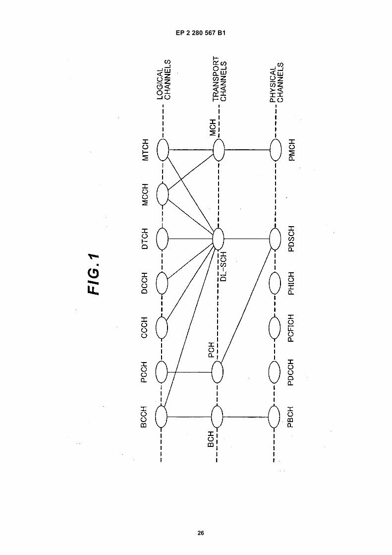
EP 2 280 567 B1
26

EP 2 280 567 B1
27

EP 2 280 567 B1
28

EP 2 280 567 B1
29
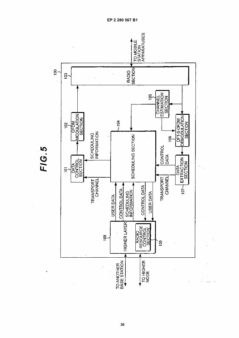
EP 2 280 567 B1
30

EP 2 280 567 B1
31

EP 2 280 567 B1
32

EP 2 280 567 B1
33

EP 2 280 567 B1
34

EP 2 280 567 B1
35

EP 2 280 567 B1
36
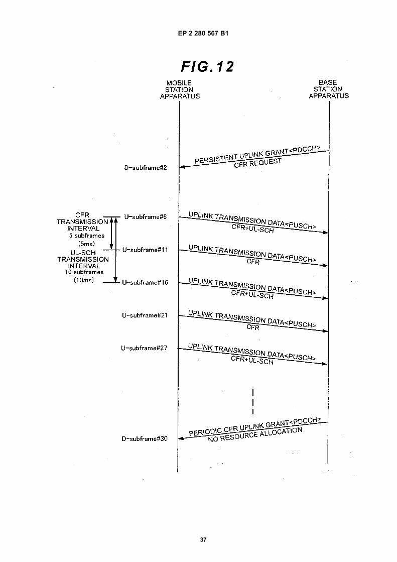
EP 2 280 567 B1
37

EP 2 280 567 B1
38

EP 2 280 567 B1
39

EP 2 280 567 B1
40

EP 2 280 567 B1
41
REFERENCES CITED IN THE DESCRIPTION
This list of references cited by the applicant is for the reader’s convenience only. It does not form part of the Europeanpatent document. Even though great care has been taken in compiling the references, errors or omissions cannot beexcluded and the EPO disclaims all liability in this regard.
Non-patent literature cited in the description
• 3GPP TS (Technical Specification) 36.300, v8.4.0,March 2008 [0015]
• 3GPP TS (Technical Specification) 36.213, V8. 2. 0,March 2008 [0015]
• ERICSSON et al. Control of semi persistent sched-uling. 3GPP DRAFT R2-080765 [0015]

![(19) TZZ Z T - patentimages.storage.googleapis.com · [0035] sali t Iso desirable toreduc e asm uch as possible the use ofal rge cranes andoth f e drawworksof rar sing i he t mast.](https://static.fdocuments.in/doc/165x107/5c1621b509d3f25e0b8bf8a7/19-tzz-z-t-0035-sali-t-iso-desirable-toreduc-e-asm-uch-as-possible-the.jpg)


![(19) TZZ T - patentimages.storage.googleapis.com · EP2 411 481B1 2 5 10 15 20 25 30 35 40 45 50 55 Description Field of the Invention [0001] The present invention relates to the](https://static.fdocuments.in/doc/165x107/5bdbe63b09d3f263278cc6e0/19-tzz-t-ep2-411-481b1-2-5-10-15-20-25-30-35-40-45-50-55-description-field.jpg)