(19) TZZ¥¥ T - Niagara Bottling...accordance with Art. 76 EPC: 12779493.1 / 2 705 091 (71)...
17
Printed by Jouve, 75001 PARIS (FR) (19) EP 3 372 644 A1 TEPZZ¥¥7 644A_T (11) EP 3 372 644 A1 (12) EUROPEAN PATENT APPLICATION (43) Date of publication: 12.09.2018 Bulletin 2018/37 (21) Application number: 18166653.8 (22) Date of filing: 03.05.2012 (51) Int Cl.: C08L 67/03 (2006.01) C08K 3/04 (2006.01) B82Y 30/00 (2011.01) (84) Designated Contracting States: AL AT BE BG CH CY CZ DE DK EE ES FI FR GB GR HR HU IE IS IT LI LT LU LV MC MK MT NL NO PL PT RO RS SE SI SK SM TR (30) Priority: 03.05.2011 US 201161482048 P (62) Document number(s) of the earlier application(s) in accordance with Art. 76 EPC: 12779493.1 / 2 705 091 (71) Applicant: The Board Of Regents For Oklahoma State University Stillwater, OK 74074 (US) (72) Inventor: HANAN, Jay Clarke Oklahoma, OK Oklahoma OK 74063 (US) (74) Representative: Script IP Limited Turnpike House 18 Bridge Street Frome Somerset BA11 1BB (GB) Remarks: This application was filed on 10-04-2018 as a divisional application to the application mentioned under INID code 62. (54) POLYETHYLENE TEREPHTHALATE-GRAPHENE NANOCOMPOSITES (57) A masterbatch product suitable for injection molding, comprising: a first portion comprised of polyeth- ylene terephthalate (PET); and a second portion com- prised of a graphene nanoplatelet material comprised of graphene nanoplatlets that is compounded with the first portion to form the masterbatch product suitable for in- jection molding, wherein the graphene nanoplatlets com- prises from two to fifteen percent by weight of the mas- terbatch.
Transcript of (19) TZZ¥¥ T - Niagara Bottling...accordance with Art. 76 EPC: 12779493.1 / 2 705 091 (71)...

Printed by Jouve, 75001 PARIS (FR)
(19)E
P3
372
644
A1
TEPZZ¥¥7 644A_T(11) EP 3 372 644 A1
(12) EUROPEAN PATENT APPLICATION
(43) Date of publication: 12.09.2018 Bulletin 2018/37
(21) Application number: 18166653.8
(22) Date of filing: 03.05.2012
(51) Int Cl.:C08L 67/03 (2006.01) C08K 3/04 (2006.01)
B82Y 30/00 (2011.01)
(84) Designated Contracting States: AL AT BE BG CH CY CZ DE DK EE ES FI FR GB GR HR HU IE IS IT LI LT LU LV MC MK MT NL NO PL PT RO RS SE SI SK SM TR
(30) Priority: 03.05.2011 US 201161482048 P
(62) Document number(s) of the earlier application(s) in accordance with Art. 76 EPC: 12779493.1 / 2 705 091
(71) Applicant: The Board Of Regents For Oklahoma State UniversityStillwater, OK 74074 (US)
(72) Inventor: HANAN, Jay ClarkeOklahoma, OK Oklahoma OK 74063 (US)
(74) Representative: Script IP LimitedTurnpike House 18 Bridge StreetFrome Somerset BA11 1BB (GB)
Remarks: This application was filed on 10-04-2018 as a divisional application to the application mentioned under INID code 62.
(54) POLYETHYLENE TEREPHTHALATE-GRAPHENE NANOCOMPOSITES
(57) A masterbatch product suitable for injectionmolding, comprising: a first portion comprised of polyeth-ylene terephthalate (PET); and a second portion com-prised of a graphene nanoplatelet material comprised ofgraphene nanoplatlets that is compounded with the first
portion to form the masterbatch product suitable for in-jection molding, wherein the graphene nanoplatlets com-prises from two to fifteen percent by weight of the mas-terbatch.

EP 3 372 644 A1
2
5
10
15
20
25
30
35
40
45
50
55
Description
FIELD OF THE INVENTION
[0001] This disclosure is related to polymers in general and, more specifically, to strengthening of polymers by intro-duction of nanomaterials.
BACKGROUND OF THE INVENTION
[0002] Polymers have become an ever-present component of modern life. Products that used to be made from metalsand other heavy materials using labor and/or energy intensive processes can now be made less expensively, morequickly, and with less energy input. Automotive, medical, information technology, and health care are but a small samplingof the industries that make ubiquitous use of polymers.[0003] Making a device from a polymer generally results in an item that is lighter in weight than an equivalent itemmade from a structural metal or other material. However, with decrease in weight generally comes a decrease in strength.The decrease in strength may be a decrease in ability to withstand torsion, shearing, compression, pressure, or anotherforce without buckling, breaking, or deforming to an unacceptable degree.[0004] What is needed is a system and method for addressing the above, and related, issues.
SUMMARY OF THE INVENTION
[0005] The invention of the present disclosure, in one aspect thereof, comprises a nanocomposite material. Thematerial contains a base polymer including polyethylene terephthalate (PET), and a nanoparticle that increases thestrength of the base polymer. The nanoparticle may comprise graphene nanoplatelets that may be prepared by exfoliation.The graphene nanoplatelets may have an average diameter of 5 micrometers. They may comprise about two percentby weigh of the nanocomposite material. In other embodiments graphene nanoplatelets may comprise about five, ten,or fifteen percent by weigh of the nanocomposite material. In another embodiment the percentage by weight may rangefrom about two to about fifteen.[0006] The invention of the present disclosure, in another aspect thereof comprises a method of producing a nano-composite material. The method includes providing polyethylene terephthalate (PET) as a base polymer, and providinga nanoparticulate substance. The method also includes compounding the base polymer with the nanoparticulate materialto form a masterbatch product, and injection molding the masterbatch product. The nanoparticulate substance maycomprise graphene. The graphene may be prepared by exfoliation.[0007] In one embodiment the nanoparticulate substance may comprises about two percent by weight of the nano-particle substance material in the masterbatch product. In other embodiments the percentage by weight may be aboutfive, ten, or fifteen. In some embodiments it may range from about two percent to about fifteen percent.
BRIEF DESCRIPTION OF THE DRAWINGS
[0008]
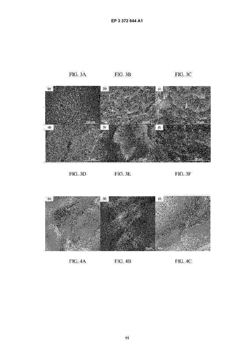
Figure 1: SEM micrographs of xGnP powder sample (a) 1000 x; (b) 11000 x.Figure 2: Tensile tested samples of PET (At) and PET-15% xGnP Nanocomposite (B).Figure 3: SEM micrographs of (a) PET, PET-xGnP Nanocomposite (b) 2% wt, (c) 5% wt, (d) 10% wt with microvoids, (e) 10% wt at 5k x and (f) 15% wt samples.Figure 4: TEM micrographs showing dispersion of the nanoplatelets in PET-15% xGnP nanocomposite; bright fieldimages (a) 10k x, (b) 20k x and (c) dark field image @ 60k x.Figure 5: Comparison of XRD patterns of xGnP powder with PET control and nanocomposite.Figure 6: Comparison of Stress-Strain curves of PET and PET-xGnP Nanocomposites.Figure 7: Young’s Modulus of PET Nanocomposites in comparison with control PET.Figure 8: Modulus of PET-graphene nanocomposites from predictions compared with experimental results.
DETAILED DESCRIPTION OF THE PREFERRED EMBODIMENTS
[0009] Base polymers may have a number of inherent characteristics relating to their appearance, color, hardness,strength, and any number of other measurable properties. In some cases, a base polymer is mixed with a predeterminedamount of a material that will alter the properties of the base polymer. The material added to the base polymer is referredto as a masterbatch and the process of adding the masterbatch to the base polymer in such a way as to alter its properties

EP 3 372 644 A1
3
5
10
15
20
25
30
35
40
45
50
55
may be referred to as a masterbatch process.[0010] Polymers may also be prepared in a masterbatch process where further processing will create a completedproduct. For example, a polymer or a nanocomposite polymer, as described below, can be prepared into masterbatchpellets that are later molded into a completed product (e.g., by injection molding or other suitable processes).[0011] In some embodiments of the present disclosure, nano-scale particles are blended or combined with a polymerinto masterbatch pellets that may then be injection molded into completed products. The nano-scale material within thepolymer of the masterbatch will only interact to alter the properties of the base polymer on a nano-scale, which providessome benefit over larger reinforcement mechanisms. Based on the Griffith crack theory and Weibull analysis, smallerparticles are stronger and can be more effective in reinforcing the matrix compared to their larger counter parts. Also,with their increased surface area and high aspect ratios, lower volumes of smaller reinforcements can provide equivalentreinforcement.[0012] Nanoparticle selection may be based on the required properties, interaction with the matrix, processing, cost,and application of the final composite. Several nanoparticles such as organoclays (MMT), metal nanoparticles (Al, andAg), metal oxides (ZnO, silica), and carbon derivatives (CNT’s, Fullerenes, Graphite oxide, graphene) may be useful inthe preparation of polymer nanocomposites. In another embodiment, polyethylene terephthalate (PET)-graphene isutilized to create polymer nanocomposites. The material is appropriate for injection and blow molding, and other process-ing and manufacturing techniques.[0013] Graphene (comprising a monolayer of carbon atoms) has excellent mechanical (modulus - 1060 GPa, Strength- 20 GPa) and electrical properties (50 x 10-6 I cm), compared with other nanoparticles. Graphene can disperse well inbase polymers through the aid of surface treatments. Exfoliated Graphene Nanoplatelets (xGnP) are multiple graphenelayers stacked to form platelets.[0014] Regarding the specific combination of PET with graphene (e.g., as in certain embodiments of the presentdisclosure), PET is a widely used polymer but has heretofore been overlooked in the laboratory studies owning in partto the fact that it is relatively sticky and has a relatively high melting point. Furthermore, the constituent mer units of PETexhibit a polarity that can result in a dissolution of certain polar nanostructures when the products are mixed. It shouldbe noted that graphene is a polar substance, meaning it might be expected to dissolve or lose its structural integrity inthe presence of PET. However, as disclosed herein, graphene can and does maintain integrity sufficiently to favorablyalter the physical characteristics of PET.[0015] In one embodiment, PET-Exfoliated graphene nanocomposites are prepared using injection molding througha masterbatch process, where graphene nanoplatelets are compounded with PET to form masterbatch pellets. Theseexperimental results were compared to theoretical performances using Halpin-Tsai and Hui-Shia models.[0016] Continuous fiber composites are often assessed based on a simplified empirical formula, referred to as the’Rule of Mixtures’. In the case of nanoreinforcements, the ’Rule of Mixtures’ either under-estimates or over-estimatesthe final properties. This can be because of their low volume fractions and often greater disparity of properties betweenthe matrix and reinforcement.[0017] For nanocomposites, the special interaction between the nanoplatelets and matrix is important in determiningtheir elastic behavior. High aspect ratios of the nanoplatelets combined with complex mechanisms at the matrix-rein-forcement interface complicate nanocomposite property estimation. Therefore, traditional micromechanical models havebeen modified to estimate the mechanical properties for nanoparticles.
Experiment 1
Materials
[0018] In one demonstration, commercially available Polyethylene Terephthalate of 0.80 dl/g (I.V.) called oZpetTM(GG-3180 FGH, by Leading Synthetics, Australia) was used. Exfoliated graphene nanoplatelets, of xGnP®-M-5 grade(99.5% carbon) of average diameter 5 Pm as shown in Figure 1, were obtained as dry powder from XG Sciences, Inc.(East Lansing, MI). Graphene nanoplatelets (xGnP) and the as received PET resin were compounded into PET-xGnPmasterbatch pellets by Ovation Polymers (Medina, OH) using their ExTima™ technology.[0019] Graphene nanoplatelets are hydrophobic in nature; effective dispersion of graphene results from the interactionof oxygen and hydroxyl functional groups (formed due to the exposure of raw carbon during the fracture of platelets) ontheir surface with polar groups of PET [19]. Master batch pellets obtained from the above process were used as rawmaterial for the injection molding process. PET control samples and PET-xGnP nanocomposite tensile bars of increasingweight fractions (2%, 5%, 10%, and 15%) were injection molded at 250°C-260°C temperature, following type -I specifi-cations of ASTM D 638 (hereby incorporated by reference).

EP 3 372 644 A1
4
5
10
15
20
25
30
35
40
45
50
55
Characterization Techniques
[0020] The produced nanocomposite tensile bars (shown in Figure 2) were tested using a universal materials tester(Instron 5582 model). Tests followed the ASTM D 638 standard at a cross-head speed of 5 mm/min. A non-contactLaser Extensometer (Electronic Instrument Research, Model LE - 05) was used to record displacement free of machinecompliance. The laser extensometer records displacement of reflections from the self-reflective stickers placed at thegauge length.[0021] Three composites of each kind were tested along with neat PET specimens for comparison. The laser dis-placement and load from the crosshead were simultaneously recorded at a time interval of 100 ms.[0022] Dispersion of the graphene nanoplatelets was observed using Electron Microscopy (SEM, TEM) and X-rayDiffraction. SEM micrographs of the xGnP powder and the fracture surfaces of the PET, and PET-Exfoliated graphenenanocomposites were obtained using a Hitachi S-4800.[0023] The PET control and the nanocomposite with lower graphene content were Au/Pt coated using a Balzers UnionMED 010 coater. Thin sections (thickness of 70 nm) used for transmission imaging were microtomed using Reichert-Jung Ultracut E microtome. Transmission micrographs were collected using a JEOL JEM-2100 Microscope, with anoperating voltage of 200 kV. X-ray diffraction patterns were collected in reflection, on a Bruker D8 Discovery diffractometer,using Cu Kα (λ = 1.54054 Å) radiation. XRD scans of the xGnP powder along with the PET samples were collected at40 kV and 40 mA with an exposure time of 120 sec.
Results
Scanning Electron Microscopy
[0024] SEM micrographs of the xGnP dry powder shown in Figure 1(b) shows an agglomerated platelet, with eachplatelet comprised of numerous graphene layers stacked together. These platelets were of 5 to 10 Pm average diameterand several nanometers (5 - 20 nm) in thickness.[0025] Micrographs (Figure 3 (b), (c), (d), (e), and (f)) of the PET-graphene nanocomposite failure surfaces showedthat the graphene nanoplatelets remained intact and were dispersed into the PET matrix, with no signs of agglomeration.The micrographs elucidate that the failure of the nanocomposite under tensile loading was through coalescence of brittlemicro-fractures. The presence of micro voids and the initiation of cracks from these voids can be noticed from the SEMmicrographs of nanocomposite samples with 5% and 10% graphene nanoplatelet weight fraction. SEM micrographsshow the nanoplatelets were projecting out of the fracture surfaces. They appear to be deformed and mixed with the matrix.
Transmission Electron Microscopy
[0026] The performance of nanocomposites depends on dispersion of the nanoparticles. TEM micrographs werecollected from 70 nm thin sections to gain better understanding of nanoplatelet dispersion. The transmission micrographsshown in Figure 4, revealed the graphene nanoplatelets remained intact as platelets and were dispersed into the polymermatrix, individual dispersion of graphene sheets (complete exfoliation) was not found. Micrographs were collected inboth bright and dark field modes. As the nanoplatelets consist of several individual graphene sheets, the 70 nm thicksections used may contain layers of polymer and graphene platelets, therefore dark field mode was advantageous.Graphene is more conductive than the polymer matrix so, in transmission imaging, this difference provides contrast.
X-ray Diffraction
[0027] XRD patterns collected from the dry xGnP powder, PET control, and PET-xGnP nanocomposite are shown inFigure 5. The diffraction pattern for the graphene nanoplatelets shows the graphene-2H characteristic peaks at 26.6°(d = 3.35 Å) and 54.7° (d = 1.68 Å) 2θ. Slight broadening of the peak at 26.6° 2θ indicates the presence of platelets withdifferent dimensions. A broad amorphous peak from the PET control sample was observed around 19.2° 2θ. This confirmsthe control sample has an amorphous microstructure. As shown in Figure 5, the intensity of the graphene peak at 26.6°2θ increased with the weight fraction of the nanoplatelets. No peak shift was observed. This along with the TEM micro-graphs confirms that the nanoplatelets were not substantially exfoliated [20]. Further, the diffraction pattern confirms thePET matrix was amorphous as expected, at least within 0.2 mm of the surface.
Mechanical Behavior
[0028] Stress-Strain curves for the PET control and nanocomposite were plotted as shown in Figure 6, based on thedata collected from the tensile tests. The addition of graphene nanoplatelets has increased the performance (modulus)

EP 3 372 644 A1
5
5
10
15
20
25
30
35
40
45
50
55
over the pure PET up to 300% and follows an exponential trend as shown in Figure 7. While primarily linear behavior isobserved, a hump in the stress strain curve for the 15% nanocomposite, suggests an additional toughening mechanismfor this composite over the other lower volume fraction. This may be due to a reinforcement-reinforcement interaction.[0029] With the objective of understanding the effectiveness of graphene nanoplatelets as reinforcement, microme-chanical models such as the Halpin-Tsai and the Hui-Shia models were used to determine the theoretical elastic me-chanical performance of this PET-graphene nanocomposite. Micromechanical models estimate the properties basedon assumptions, such as perfect reinforcements, homogenous dispersion, or consistent orientation of the reinforcements.An ideal case for superior performance of the graphene nanocomposite is to have defect free graphene sheets (mon-olayers) of the required length well dispersed in to the matrix and orientated along the direction of maximum load.[0030] Gong et al. [16] have determined a required length for graphene platelets (>30 mm) to be effective as reinforce-ment. Mechanical properties of the graphene platelets such as stiffness and Poisson’s ratio decrease with increase inthe number of comprising layers, as observed by Georgantzinos et al. [22] with molecular simulations. They estimatedthat the stiffness of platelet comprising five layers decreases by 15% compared to single layer graphene, and they alsonoticed that the properties of the graphene differ based on their orientation. Modulus of the graphene platelet (flake) hasbeen reported as 0.795 TPa [23].
[0031] In the present work, graphene platelets with a wide range of length (or diameter of the platelets present in theout of plane direction) and thickness were observed from the TEM micrographs. The change of particle size from thelarger (5 mm) dry graphene powder to the smaller (300 nm), size as observed in the TEM images (Figure 4) can be dueto shearing during the compounding and molding process. Table 1 shows the average size of the platelets with minimumand maximum values. These platelet properties were then used in determining the performance range of the nanocom-posites, based on the micromechanical models (error bars shown in Figure 8). Predicted moduli of the nanocompositefrom the micromechanical models were plotted against the experimental results, shown in Figure 8. The modulus esti-mated through the Halpin-Tsai model is higher compared to the experimental value. The Halpin-Tsai model estimatesthe modulus of the composite with platelets being aligned along the loading direction. However, the platelets were notgenerally aligned in the direction of the loading. In addition, extremely high stiffness of the reinforcement compared withthe matrix (>250x), make difficult accurate predictions through the Halpin-Tsai model [22]. The Hui-Shia model showsthe best agreement. The Hui-Shia model estimates elastic modulus of the nanocomposite with platelets loaded both inparallel (axes 1 and 2) and perpendicular directions (along axis 3) as shown in Figure 8. This model is valid for widerange of stiffness ratios over the Halpin-Tsai model [22].[0032] In addition, stress transfer between the matrix to reinforcement in composites is critical in controlling theirmechanical behavior. For example, graphene nanocomposites in PMMA matrix, the stress transfer between the matrixand graphene platelets and graphene-graphene sheets were shown dominated by week van der Waals forces, reducingthe potential mechanical performance. However, micromechanical models do not account these changes in stresstransfer behavior. This results a deviation from the experimental values.[0033] The current experimental modulus showed reasonable agreement with theoretical predictions. This is in spiteof the broad range in platelet geometry (see table). The best case was the Hui-Shia model with the modulus parallel tothe platelet (direction - 3). This suggests reasonable effectiveness of the reinforcement. With the reinforcement distributedrandomly, behavior between the two Hui-Shia predictions of parallel and perpendicular might be expected. Furtherinvestigation to the randomness of the platelet distribution is needed for additional assessment. Even stiffer modulusenhancement could be expected if the platelets were of higher aspect ratio as the modulus predicted are sensitive tothe aspect ratio. This is a reasonable goal with continued improvement in the production of the additives and theirprocessing with the matrix. Clearly, nanoscale reinforcement is a benefit to the enhancement of mechanical properties.[0034] Furthermore, from X-ray diffraction, the addition of graphene platelets does not show an impact on the finalcrystallization of PET. Economies of scale can improve the cost of any of these additives. More understanding of theeffect nanoplatelets have on the injection molding process can help improve the composite properties further. Forexample, many different screw types are available for injection molding and need to be explored for their advantagesin mixing and dispersion of additives.
Table 1: Properties of Graphene and PET used for theoretical predictions
Graphene Platelet PropertiesPET
Properties
Average Length/Diameter (D) nanometers (min/max)
Average Thickness (t) nanometers (min/max)
Aspect Ratio (D/t)
Modulus (GPa)
Modulus (GPa)
300 (28/730) 16(3/28) 18.75 795 2.7
EP 3 372 644 A1
6
5
10
15
20
25
30
35
40
45
50
55
Conclusions from Tests
[0035] The present disclosure demonstrates that graphene nanoplatelets are effective in achieving improved strengthcharacteristics (such as elastic modulus) for Poly ethylene Terephthalate, or PET. Injection molding of masterbatchpellets is one successful method for preparation of PET-Exfoliated graphene (xGnP) nanocomposites of weight fractionsfrom 2-15%. Comparison with simple mechanical models suggests their superior performance. The stiffness may notonly dependent on the reinforcement stiffness, but also on its aspect ratio and the dominating mechanism for interfacialstress transfer between matrix and reinforcement. There is also some indication that the reinforcement-reinforcementinteraction plays an important role as the volume fraction exceeds 10%.
References
[0036]
[1] T. Kuila, S. Bhadra, D. Yao, N. H. Kim, S. Bose, and J. H. Lee, "Recent advances in graphene based polymercomposites," Progress in Polymer Science, vol. In Press, Corrected Proof.
[2] H. Fukushima, "Graphite Nanoreinforcements in Polymer Nanocomposites," in Chemical Engineering and Ma-terials Science. vol. Doctor of Philosophy, 2003, p. 311.
[3] X. Jiang and L. T. Drzal, "Multifunctional high density polyethylene nanocomposites produced by incorporationof exfoliated graphite nanoplatelets 1: Morphology and mechanical properties," Polymer Composites, vol. 31, pp.1091-1098.
[4] F. Hussain, M. Hojjati, M. Okamoto, and R. E. Gorga, "Review article: Polymer-matrix Nanocomposites, Process-ing, Manufacturing, and Application: An Overview," Journal of Composite Materials, vol. 40, pp. 1511-1575, Sep-tember 1, 2006 2006.
[5] D. R. Paul and L. M. Robeson, "Polymer nanotechnology: Nanocomposites," Polymer, vol. 49, pp. 3187-3204,2008.
[6] H. C. Schniepp, J.-L. Li, M. J. McAllister, H. Sai, M. Herrera-Alonso, D. H. Adamson, R. K. Prud’homme, R. Car,D. A. Saville, and I. A. Aksay, "Functionalized Single Graphene Sheets Derived from Splitting Graphite Oxide," TheJournal of Physical Chemistry B, vol. 110, pp. 8535-8539, 2006.
[7] B. Jang and A. Zhamu, "Processing of nanographene platelets (NGPs) and NGP nanocomposites: a review,"Journal of Materials Science, vol. 43, pp. 5092-5101,2008.
[8] K. Wakabayashi, C. Pierre, D. A. Dikin, R. S. Ruoff, T. Ramanathan, L. C. Brinson, and J. M. Torkelson, "Polymer-Graphite Nanocomposites: Effective Dispersion and Major Property Enhancement via Solid-State Shear Pulveriza-tion," Macromolecules, vol. 41, pp. 1905-1908, 2008.
[9] I. H. Kim and Y. G. Jeong, "Polylactide/exfoliated graphite nanocomposites with enhanced thermal stability,mechanical modulus, and electrical conductivity," Journal of Polymer Science Part B: Polymer Physics, vol. 48, pp.850-858, 2010.
[10] F. M. Uhl, Q. Yao, H. Nakajima, E. Manias, and C. A. Wilkie, "Expandable graphite/polyamide-6 nanocomposites,"Polymer Degradation and Stability, vol. 89, pp. 70-84, 2005.
[11] M. A. Rafiee, J. Rafiee, Z. Wang, H. Song, Z.-Z. Yu, and N. Koratkar, "Enhanced Mechanical Properties ofNanocomposites at Low Graphene Content," ACS Nano, vol. 3, pp. 3884-3890, 2009.
[12] K. Kalaitzidou, H. Fukushima, and L. T. Drzal, "A new compounding method for exfoliated graphite-polypropylenenanocomposites with enhanced flexural properties and lower percolation threshold," Composites Science and Tech-nology, vol. 67, pp. 2045-2051, 2007.
[13] D. G. Miloaga, H. A. A. Hosein, M. Misra, and L. T. Drzal, "Crystallization of poly(3-hydroxybutyrate) by exfoliatedgraphite nanoplatelets," Journal of Applied Polymer Science, vol. 106, pp. 2548-2558, 2007.
EP 3 372 644 A1
7
5
10
15
20
25
30
35
40
45
50
55
[14] A. S. Patole, S. P. Patole, H. Kang, J.-B. Yoo, T.-H. Kim, and J.-H. Ahn, "A facile approach to the fabricationof graphene/polystyrene nanocomposite by in situ microemulsion polymerization," Journal of Colloid and InterfaceScience, vol. 350, pp. 530-537, 2010.
[15] Y. C. Li and G. H. Chen, "HDPE/expanded graphite nanocomposites prepared via masterbatch process,"Polymer Engineering & Science, vol. 47, pp. 882-888, 2007.
[16] H. Hu, L. Onyebueke, and A. Abatan, "Characterizing and Modeling Mechanical Properties of nanocomposites- Review and Evaluation," Journal of Minerals & Materials Characterization & Engineering, vol. 9, p. 45, 2010.
[17] P. A. Beale, "Global Polyester Raw Materials Dynamics," in The Packaging Conference, Las Vegas, 2011.
[18] J.-H. Chang, S. J. Kim, Y. L. Joo, and S. Im, "Poly(ethylene terephthalate) nanocomposites by in situ interlayerpolymerization: the thermo-mechanical properties and morphology of the hybrid fibers," Polymer, vol. 45, pp.919-926, 2004.
[19] A. A. K, U. S. Agarwal, and R. Joseph, "Carbon nanotubes-reinforced PET nanocomposite by melt-compound-ing," Journal of Applied Polymer Science, vol. 104, pp. 3090-3095, 2007.
[20] H.-B. Zhang, W.-G. Zheng, Q. Yan, Y. Yang, J.-W. Wang, Z.-H. Lu, G.-Y. Ji, and Z.-Z. Yu, "Electrically conductivepolyethylene terephthalate/graphene nanocomposites prepared by melt compounding," Polymer, vol. 51, pp.1191-1196, 2010.
[21] A. B. Morgan and J. W. Gilman, "Characterization of polymer-layered silicate (clay) nanocomposites by trans-mission electron microscopy and X-ray diffraction: A comparative study," Journal of Applied Polymer Science, vol.87, pp. 1329-1338, 2003.
[22] C. Y. Hui and D. Shia, "Simple formulae for the effective moduli of unidirectional aligned composites," PolymerEngineering & Science, vol. 38, pp. 774-782, 1998.
[23] O. L. Blakslee, D. G. Proctor, E. J. Seldin, G. B. Spence, and T. Weng, "Elastic Constants of Compression-Annealed Pyrolytic Graphite," Journal of Applied Physics, vol. 41, pp. 3373-3382, 1970.
[24] C. Y. Hui and D. Shia, "Simple formulae for the effective moduli of unidirectional aligned composites," PolymerEngineering & Science, vol. 38, pp. 774-782, 1998.
[25] D. Shia, C. Y. Hui, S. D. Burnside, and E. P. Giannelis, "An interface model for the prediction of Young’s modulusof layered silicate-elastomer nanocomposites," Polymer Composites, vol. 19, pp. 608-617, 1998.
[26] H. Hua, L. Onyebueke, and A. Abatan, "Characterizing and Modeling Mechanical Properties of Nanocomposites-Review and Evaluation," Journal of Minerals & Materials Characterization & Engineering, vol. 9, pp. 275-319, 2010.
[27] J. C. H. Affdl and J. L. Kardos, "The Halpin-Tsai equations: A review," Polymer Engineering & Science, vol. 16,pp. 344-352, 1976.
[0037] Further features are described in the following paragraphs (a) to (q):
(a) A nanocomposite material comprising:
a base polymer including polyethylene terephthalate (PET); and
a nanoparticle that increases the strength of the base polymer.
(b) The material of paragraph (a), wherein the nanoparticle comprises graphene nanoplatelets.
(c) The material of paragraph (a), wherein the graphene comprises exfoliated nanoplatelets.
(d) The material of paragraph (b), wherein the graphene nanoplatelets have an average diameter of 5 micrometers.

EP 3 372 644 A1
8
5
10
15
20
25
30
35
40
45
50
55
(e) The material of paragraph (b), wherein the nanoplatelets comprise about two percent by weight of the nanocom-posite material.
(f) The material of paragraph (b), wherein the nanoplatelets comprise about five percent by weight of the nanocom-posite material.
(g) The material of paragraph (b), wherein the nanoplatelets comprise about ten percent by weight of the nanocom-posite material.
(h) The material of paragraph (b), wherein the nanoplatelets comprise about 15 percent by weight of the nanocom-posite material.
(i) The material of paragraph (b), wherein the nanoplatelets comprise from about two to about fifteen percent byweight of the nanocomposite material.
(j) A method of producing a nanocomposite material comprising:
providing polyethylene terephthalate (PET) as a base polymer;providing a nanoparticulate substance;compounding the base polymer with the nanoparticulate material to form a masterbatch product; andinjection molding the masterbatch product.
(k) The method of paragraph (j), wherein providing a nanoparticulate substance further comprises providing graph-ene.
(l) The method of paragraph (k), further comprising preparing the graphene by exfoliation.
(m) The method of paragraph (j), wherein providing a nanoparticulate substance further comprises providing abouttwo percent by weight of the nanoparticle substance material in the masterbatch product.
(n) The method of paragraph (j), wherein providing a nanoparticulate substance further comprises providing aboutfive percent by weight of the nanoparticle substance material in the masterbatch product.
(o) The method of paragraph (j), wherein providing a nanoparticulate substance further comprises providing aboutten percent by weight of then nanoparticle substance material in the masterbatch product.
(p) The method of paragraph (j), wherein providing a nanoparticulate substance further comprises providing aboutfifteen percent by weight of then nanoparticle substance material in the masterbatch product.
(q) The method of paragraph (j), wherein providing a nanoparticulate substance further comprises providing fromabout two percent to about fifteen percent by weight of the nanoparticle substance material in the masterbatchproduct.
[0038] Thus, the present invention is well adapted to carry out the objectives and attain the ends and advantagesmentioned above as well as those inherent therein. While presently preferred embodiments have been described forpurposes of this disclosure, numerous changes and modifications will be apparent to those of ordinary skill in the art.Such changes and modifications are encompassed within the spirit of this invention as defined by the claims.
Claims
1. A masterbatch product suitable for injection molding, comprising:
a first portion comprised of polyethylene terephthalate (PET); anda second portion comprised of a graphene nanoplatelet material comprised of graphene nanoplatlets that iscompounded with the first portion to form the masterbatch product suitable for injection molding, wherein thegraphene nanoplatlets comprises from two to fifteen percent by weight of the masterbatch.

EP 3 372 644 A1
9
5
10
15
20
25
30
35
40
45
50
55
2. The masterbatch product of claim 1, wherein the second portion comprises between ten and fifteen percent byweight of the masterbatch product.
3. The masterbatch product of claim 1 or 2, wherein the graphene nanoplatelet material is comprised of nanoplateletshaving an average diameter of 5 micrometers.
4. The masterbatch product of any one of the preceding claims, wherein the graphene nanoplatelet material is comprisedof an exfoliated graphene .
5. The masterbatch product of claim 4, wherein the graphene nanoplatelet material is comprised of multiple stackedgraphene layers.
6. The masterbatch product of claim 1, wherein the graphene nanoplatelet material is compounded with the PET toform a nanocomposite material that possesses a greater elastic modulus than pure PET.
7. The masterbatch product of any one of the preceding claims, wherein the masterbatch material is configured intomasterbatch pellets that are suitable for an injection molding process or a blow-molding process.
8. A method for forming a masterbatch product suitable for injection molding, comprising:
obtaining a first portion that is comprised of polyethylene terephthalate (PET) base polymer; providing a secondportion that is comprised of a graphene nanoplatelet material that includes exfoliated nanoplatelets having anaverage diameter of 5 micrometers; selecting a quantity of the second portion to produce a desired percentageby weight of the masterbatch product, wherein said exfoliated nanoplatlets comprise from two to fifteen percentby weight of the masterbatch product;compounding the first portion with the second portion to create the masterbach product, andconfiguring the masterbach product to be suitable for further processing to create a completed product.
9. The method of claim 8, wherein selecting the quantity of the second portion comprises forming a nanocompositematerial possessing a greater elastic modulus than pure PET.
10. The method of claim 8 or 9, wherein selecting the quantity of the second portion comprises producing between tenand fifteen percent by weight of the masterbatch product.
11. The method of claim 8, 9 or 10, wherein configuring the masterbatch product comprises forming the masterbatchproduct into pellets that are suitable for an injection molding process or a blow-molding process.

EP 3 372 644 A1
10
EP 3 372 644 A1
11

EP 3 372 644 A1
12

EP 3 372 644 A1
13

EP 3 372 644 A1
14
5
10
15
20
25
30
35
40
45
50
55

EP 3 372 644 A1
15
5
10
15
20
25
30
35
40
45
50
55

EP 3 372 644 A1
16
REFERENCES CITED IN THE DESCRIPTION
This list of references cited by the applicant is for the reader’s convenience only. It does not form part of the Europeanpatent document. Even though great care has been taken in compiling the references, errors or omissions cannot beexcluded and the EPO disclaims all liability in this regard.
Non-patent literature cited in the description
• T. KUILA ; S. BHADRA ; D. YAO ; N. H. KIM ; S.BOSE ; J. H. LEE. Recent advances in graphenebased polymer composites. Progress in Polymer Sci-ence [0036]
• H. FUKUSHIMA. Graphite Nanoreinforcements inPolymer Nanocomposites. Chemical Engineeringand Materials Science, 2003, 311 [0036]
• X. JIANG ; L. T. DRZAL. Multifunctional high densitypolyethylene nanocomposites produced by incorpo-ration of exfoliated graphite nanoplatelets 1: Morphol-ogy and mechanical properties. Polymer Compos-ites, vol. 31, 1091-1098 [0036]
• F. HUSSAIN ; M. HOJJATI ; M. OKAMOTO ; R. E.GORGA. Review article: Polymer-matrix Nanocom-posites, Processing, Manufacturing, and Application:An Overview. Journal of Composite Materials, 01September 2006, vol. 40, 1511-1575 [0036]
• D. R. PAUL ; L. M. ROBESON. Polymer nanotech-nology: Nanocomposites. Polymer, 2008, vol. 49,3187-3204 [0036]
• H. C. SCHNIEPP ; J.-L. LI ; M. J. MCALLISTER ; H.SAI ; M. HERRERA-ALONSO ; D. H. ADAMSON ;R. K. PRUD’HOMME ; R. CAR ; D. A. SAVILLE ; I.A. AKSAY. Functionalized Single Graphene SheetsDerived from Splitting Graphite Oxide. The Journalof Physical Chemistry B, 2006, vol. 110, 8535-8539[0036]
• B. JANG ; A. ZHAMU. Processing of nanographeneplatelets (NGPs) and NGP nanocomposites: a re-view. Journal of Materials Science, 2008, vol. 43,5092-5101 [0036]
• K. WAKABAYASHI ; C. PIERRE ; D. A. DIKIN ; R.S. RUOFF ; T. RAMANATHAN ; L. C. BRINSON ;J. M. TORKELSON. Polymer-Graphite Nanocom-posites: Effective Dispersion and Major Property En-hancement via Solid-State Shear Pulverization. Mac-romolecules, 2008, vol. 41, 1905-1908 [0036]
• Journal of Polymer Science Part B: Polymer Physics,2010, vol. 48, 850-858 [0036]
• Polymer Degradation and Stability, 2005, vol. 89,70-84 [0036]
• M. A. RAFIEE ; J. RAFIEE ; Z. WANG ; H. SONG ;Z.-Z. YU ; N. KORATKAR. Enhanced MechanicalProperties of Nanocomposites at Low GrapheneContent. ACS Nano, 2009, vol. 3, 3884-3890 [0036]
• K. KALAITZIDOU ; H. FUKUSHIMA ; L. T. DRZAL.A new compounding method for exfoliated graph-ite-polypropylene nanocomposites with enhancedflexural properties and lower percolation threshold.Composites Science and Technology, 2007, vol. 67,2045-2051 [0036]
• D. G. MILOAGA ; H. A. A. HOSEIN ; M. MISRA ; L.T. DRZAL. Crystallization of poly(3-hydroxybutyrate)by exfoliated graphite nanoplatelets. Journal of Ap-plied Polymer Science, 2007, vol. 106, 2548-2558[0036]
• A. S. PATOLE ; S. P. PATOLE ; H. KANG ; J.-B.YOO ; T.-H. KIM ; J.-H. AHN. A facile approach tothe fabrication of graphene/polystyrene nanocom-posite by in situ microemulsion polymerization. Jour-nal of Colloid and Interface Science, 2010, vol. 350,530-537 [0036]
• Y. C. LI ; G. H. CHEN. HDPE/expanded graphite na-nocomposites prepared via masterbatch process.Polymer Engineering & Science, 2007, vol. 47,882-888 [0036]
• H. HU ; L. ONYEBUEKE ; A. ABATAN. Character-izing and Modeling Mechanical Properties of nano-composites - Review and Evaluation. Journal of Min-erals & Materials Characterization & Engineering,2010, vol. 9, 45 [0036]
• P. A. BEALE. Global Polyester Raw Materials Dy-namics. The Packaging Conference, 2011 [0036]
• J.-H. CHANG ; S. J. KIM ; Y. L. JOO ; S. IM. Po-ly(ethylene terephthalate) nanocomposites by in situinterlayer polymerization: the thermo-mechanicalproperties and morphology of the hybrid fibers. Pol-ymer, 2004, vol. 45, 919-926 [0036]
• A. A. K ; U. S. AGARWAL ; R. JOSEPH. Carbonnanotubes-reinforced PET nanocomposite bymelt-compounding. Journal of Applied Polymer Sci-ence, 2007, vol. 104, 3090-3095 [0036]
• H.-B. ZHANG ; W.-G. ZHENG ; Q. YAN ; Y. YANG ;J.-W. WANG ; Z.-H. LU ; G.-Y. JI ; Z.-Z. YU. Electri-cally conductive polyethylene terephthalate/graph-ene nanocomposites prepared by melt compound-ing. Polymer, 2010, vol. 51 [0036]
• A. B. MORGAN ; J. W. GILMAN. Characterizationof polymer-layered silicate (clay) nanocomposites bytransmission electron microscopy and X-ray diffrac-tion: A comparative study. Journal of Applied PolymerScience, 2003, vol. 87, 1329-1338 [0036]

EP 3 372 644 A1
17
• C. Y. HUI ; D. SHIA. Simple formulae for the effectivemoduli of unidirectional aligned composites. PolymerEngineering & Science, 1998, vol. 38, 774-782 [0036]
• O. L. BLAKSLEE ; D. G. PROCTOR ; E. J. SELDIN ;G. B. SPENCE ; T. WENG. Elastic Constants of Com-pression-Annealed Pyrolytic Graphite. Journal of Ap-plied Physics, 1970, vol. 41, 3373-3382 [0036]
• D. SHIA ; C. Y. HUI ; S. D. BURNSIDE ; E. P. GIAN-NELIS. An interface model for the prediction ofYoung’s modulus of layered silicate-elastomer nano-composites. Polymer Composites, 1998, vol. 19,608-617 [0036]
• H. HUA ; L. ONYEBUEKE ; A. ABATAN. Character-izing and Modeling Mechanical Properties of Nano-composites-Review and Evaluation. Journal of Min-erals & Materials Characterization & Engineering,2010, vol. 9, 275-319 [0036]
• J. C. H. AFFDL ; J. L. KARDOS. The Halpin-Tsaiequations: A review. Polymer Engineering & Science,1976, vol. 16, 344-352 [0036]