
18TFSI
8
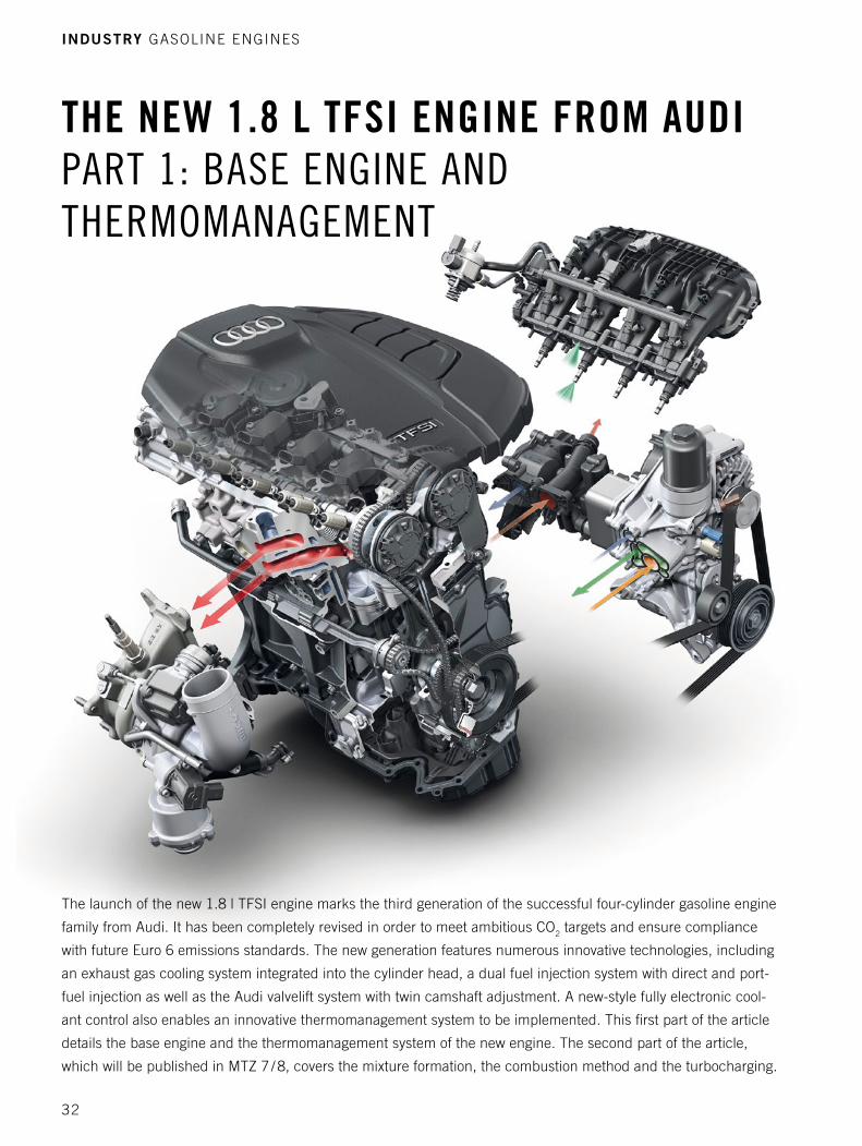
THE NEW 1.8 L TFSI ENGINE FROM AUDI PART 1: BASE ENGINE AND THERMOMANAGEMENT The launch of the new 1.8 l TFSI engine marks the third generation of the successful four-cylinder gasoline engine family from Audi. It has been completely revised in order to meet ambitious CO 2 targets and ensure compliance with future Euro 6 emissions standards. The new generation features numerous innovative technologies, including an exhaust gas cooling system integrated into the cylinder head, a dual fuel injection system with direct and port- fuel injection as well as the Audi valvelift system with twin camshaft adjustment. A new-style fully electronic cool- ant control also enables an innovative thermomanagement system to be implemented. This first part of the article details the base engine and the thermomanagement system of the new engine. The second part of the article, which will be published in MTZ 7 / 8, covers the mixture formation, the combustion method and the turbocharging. INDUSTRY GASOLINE ENGINES 32
Transcript of 18TFSI
The new 1.8 l TFSI engIne From AudI Part 1: Base engine and thermomanagement
The launch of the new 1.8 l TFSI engine marks the third generation of the successful four-cylinder gasoline engine
family from Audi. It has been completely revised in order to meet ambitious CO2 targets and ensure compliance
with future Euro 6 emissions standards. The new generation features numerous innovative technologies, including
an exhaust gas cooling system integrated into the cylinder head, a dual fuel injection system with direct and port-
fuel injection as well as the Audi valvelift system with twin camshaft adjustment. A new-style fully electronic cool-
ant control also enables an innovative thermomanagement system to be implemented. This first part of the article
details the base engine and the thermomanagement system of the new engine. The second part of the article,
which will be published in MTZ 7 / 8, covers the mixture formation, the combustion method and the turbocharging.
Industry GASOlInE EnGInES
32
IntroductIon and revIew
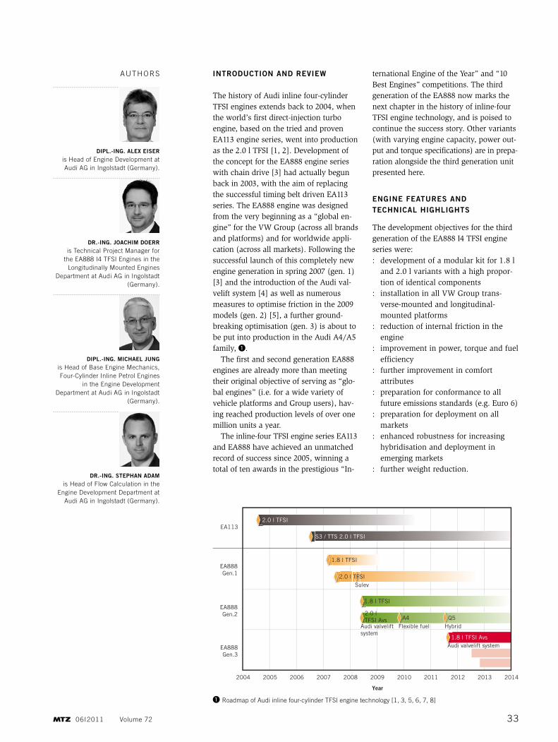
The history of Audi inline four-cylinder TFSI engines extends back to 2004, when the world’s first direct-injection turbo engine, based on the tried and proven EA113 engine series, went into production as the 2.0 l TFSI [1, 2]. Development of the concept for the EA888 engine series with chain drive [3] had actually begun back in 2003, with the aim of replacing the successful timing belt driven EA113 series. The EA888 engine was designed from the very beginning as a “global en -gine” for the VW Group (across all brands and platforms) and for worldwide appli-cation (across all markets). Following the successful launch of this completely new engine generation in spring 2007 (gen. 1) [3] and the introduction of the Audi val-velift system [4] as well as numerous measures to optimise friction in the 2009 models (gen. 2) [5], a further ground-breaking optimisation (gen. 3) is about to be put into production in the Audi A4/A5 family, ❶.
The first and second generation EA888 engines are already more than meeting their original objective of serving as “glo-bal engines” (i.e. for a wide variety of vehicle platforms and Group users), hav-ing reached production levels of over one million units a year.
The inline-four TFSI engine series EA113 and EA888 have achieved an unmatched record of success since 2005, winning a total of ten awards in the prestigious “In -
ternational Engine of the Year” and “10 Best Engines” competitions. The third generation of the EA888 now marks the next chapter in the history of inline-four TFSI engine technology, and is poised to continue the success story. Other variants (with varying engine capacity, power out-put and torque specifications) are in prepa-ration alongside the third generation unit presented here.
engIne features and technIcal hIghlIghts
The development objectives for the third generation of the EA888 I4 TFSI engine series were: : development of a modular kit for 1.8 l
and 2.0 l variants with a high propor-tion of identical components
: installation in all VW Group trans-verse-mounted and longitudinal-mounted platforms
: reduction of internal friction in the engine
: improvement in power, torque and fuel efficiency
: further improvement in comfort attributes
: preparation for conformance to all future emissions standards (e.g. Euro 6)
: preparation for deployment on all markets
: enhanced robustness for increasing hybridisation and deployment in emerging markets
: further weight reduction.
dIpl.-Ing. alex eIser is Head of Engine Development at Audi AG in Ingolstadt (Germany).
dr.-Ing. JoachIm doerr is Technical Project Manager for
the EA888 I4 TFSI Engines in the longitudinally Mounted Engines
Department at Audi AG in Ingolstadt (Germany).
dIpl.-Ing. mIchael Jung is Head of Base Engine Mechanics, Four-Cylinder Inline Petrol Engines
in the Engine Development Department at Audi AG in Ingolstadt
(Germany).
dr.-Ing. stephan adam is Head of Flow Calculation in the
Engine Development Department at Audi AG in Ingolstadt (Germany).
AuTHOrS
2004 2005 2006 2007 2008 2009
Year
2010 2011 2012 2013 2014
EA1132.0 l TFSI
S3 / TTS 2.0 l TFSI
1.8 l TFSI
2.0 l TFSI
2.0 l TFSI Avs A4 Q5
1.8 l TFSI
1.8 l TFSI Avs
Sulev
Audi valvelift system
Audi valvelift system
Flexible fuel Hybrid
EA888Gen.1
EA888Gen.2
EA888Gen.3
❶ roadmap of Audi inline four-cylinder TFSI engine technology [1, 3, 5, 6, 7, 8]
3306I2011 Volume 72
For the third generation of the EA888 engine, the tried and proven power train layout with Lancaster balance was adopted, also incorporating further improvements in terms of internal friction. For example, the main bearing diameter has been fur-ther reduced; the balance shafts are in part roller bearing mounted; and the pressu-rised oil circuit, including the control oil pump, has been optimised.
To improve the torque characteristic, the tried and proven Audi valvelift system
has been adopted from the 2.0 l second generation predecessor engine, and an additional exhaust camshaft adjuster has been integrated. The high torque of 320 Nm at 1500 rpm delivers outstanding perfor-mance, but also in particular low con-sumption figures based on modified gear-box transmission ratios (downspeeding).
An entirely new cylinder head has been developed for the third generation EA888 and, for the first time in this power and torque class, the exhaust gas recirculation
is fully integrated to the turbocharger. This water-cooled integrated exhaust gas cooling system makes it possible to reduce full-load consumption considerably.
To provide intelligent control of the en -gine’s heat flows (thermomanagement), a new-style rotary slide module has been developed to provide fully electronic cool-ant control. In the engine’s warm-up phase for example, it is able to completely block the coolant from entering the engine or set a minimal volumetric flow. When the engine is warmed up, the coolant tempera-ture can be quickly and fully variably adjusted to various temperature levels according to the load demand and exter-nal conditions.
In order to comply with the future Euro 6 emissions standard, Audi has for the first time developed a dual fuel injection sys-tem with FSI and MPI injection. The abil-ity to freely select the injection mode means that particulate emissions can be reduced significantly across wide map ranges and consumption can also be cut.
The weight of the new EA888 series has been significantly reduced again, despite numerous additional CO
2 measures. Key factors in this are the thin-walled engine block (3 mm thick), a weight-optimised crankshaft, the integrated exhaust gas cooling system cylinder head integrated exhaust manifold, a plastic oil pan, and the use of aluminium bolts.
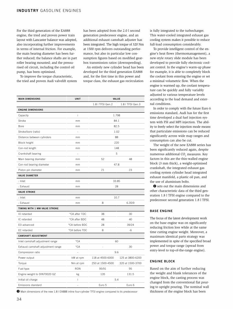
❷ sets out the main dimensions and other characteristic data of the third gen-eration 1.8 l TFSI engine compared to the predecessor second generation 1.8 l TFSI.
Base engIne
The focus of the latest development work on the base engine was on significantly reducing friction loss while at the same time cutting engine weight. Moreover, a maximum identical parts strategy was implemented in spite of the specified broad power and torque range (spread from entry-level to top-of-the-range engine).
engIne Block
Based on the aim of further reducing the weight and blank tolerances of the engine block, the casting process was changed from the conventional flat pour-ing to upright pouring. The nominal wall thickness of the engine block has been ❷ Main dimensions of the new 1.8 l EA888 inline four-cylinder TFSI engine compared to its predecessor
maIn dImensIons unIt value
1.8 l TFSI Gen.2 1.8 l TFSI Gen.3
engIne dImensIons
Capacity i 1.798
Stroke mm 84.1
Bore mm 82.5
Stroke/bore (ratio) - 1.02
Distance between cylinders mm 88
Block height mm 220
Con-rod length mm 148
Crankshaft bearing - 5
Main bearing diameter mm 52 48
Con-rod bearing diameter mm 47.8
Piston pin diameter mm 21 23
valve dIameter
: Inlet mm 33.85
: Exhaust mm 28
valve stroke
: Inlet mm 10.7
: Exhaust mm 8 6.35/9
tImIng wIth 1 mm valve stroke
IO retarded °CA after TDC 38 30
IC retarded °CA after BDC 48 40
EO advanced °CA before BDC 28 39/24
EC retarded °CA before TDC 8 -6
camshaft adJustment
Inlet camshaft adjustment range °CA 60
Exhaust camshaft adjustment range °CA - 30
Compression ratio - 9.6
Power output kW at rpm 118 at 4500-6000 125 at 3800-6200
Torque nm at rpm 250 at 1500-4500 320 at 1500-3700
Fuel type rOn 95/91 95
Engine weight to DIn70020 GZ kg 135 131.5
Initial oil charge l 5.4
Emissions standard - Euro 5 Euro 6
Industry GASOlInE EnGInES
34

reduced from 3.5 mm +/- 0.8 mm to 3.0 mm +/- 0.5 mm and, thanks to greater freedoms in the core pack, addi-tional functions could be integrated into the engine block. The function of the coarse oil separator has been integrated into the engine block casting, so eliminat-ing the need for the bolted-on coarse oil separator and the flange face on the engine block. Adjusted to function, these engine block-related measures delivered a 2.4 kg weight saving. To further improve the comfort properties of the engine, the main bearing covers have been bolted to the top section of the oil pan.
crank drIve and Balance shafts
The main bearing diameters of the crank-shaft have been reduced from 52 mm to 48 mm in order to cut friction, and the number of counterweights has been reduced from eight to four. This reduced the weight of the crankshaft by 1.6 kg. The pistons feature a newly developed, strength-enhanced alloy. In the course of this development, piston play was enlarged to optimise friction and piston wear was adapted based on a wear-resistant piston skirt coating with nanoparticles. The bal-ance shaft concept has been changed to roller bearings, ❸.
At low oil temperatures especially, the roller bearing mounting of the balance shafts results in substantially reduced fric-tion loss. In addition, intensive optimisation of the topology helped reduce system mass by 20 % and rotational inertia by 30 %, while retaining the same mass balancing.
oIl cIrculatIon
The following measures were implemented on the engine in order to reduce the power consumption of the control oil pump: : reduction in displacement via oil
temperature : optimised pressure losses in the pres-
surised oil ducts : reduction in oil pressure level in the
low pressure stage to 1.5 bar : extension of the operating range of the
low pressure stage to 4500 rpm.In addition to a further improvement in the efficiency of the control oil pump, the piston cooling has been changed from conventional spring-loaded spray nozzles
to an electrically switchable system, ❹. When current is applied to the electric control valve it releases a small control channel to the rear of the mechanical switching valve (piston spray nozzles off), allowing the electric control valve to be designed in a compact, low-cost manner. With no current applied, the mechanical switching valve is pushed up by the applied oil pressure, so releasing the sec-
ond oil gallery to the piston cooling noz-zles (fail-safe). Both valves are located directly downstream of the oil cooler and oil filter in the ancillary components holder. The new system enables needs-oriented data acquisition for piston cool-ing and with regard to thermomanage-ment and thermodynamics. System diag-nosis is implemented by way of a dedicated oil pressure switch.
❸ Crank drive with lancaster balance as well as chain drives for camshafts, balance shafts and oil pump
❹ Pressurised oil circuit and section through the actuator system for the switchable piston spray nozzles
3506I2011 Volume 72

Thanks to all the friction-reducing measures on the base engine, the new EA888 third generation engine series rede-fines the friction loss spread for turbo-charged four-cylinder gasoline engines, ❺.
cylInder head
For the new EA888 third generation engine series, a cylinder head integrated exhaust gas cooling/routing system with ignition sequence separation has been implemented for the first time for turbo-charged direct-injection gasoline engines, ❻. This water-cooled exhaust manifold means that the need for full load enrich-ment is eliminated almost entirely. As a result, consumption can be greatly reduced both in normal customer driving and, especially, when employing a more sporty driving style. Moreover, the inte-grated exhaust manifold aids rapid heat-up of the coolant and so is a key compo-nent of the thermo management system. Another advantage lies in the conver-gence of the gas ducts while still in the cylinder head, which results in a compar-atively compact and light turbocharger module. Consequently, the overall cylin-der head/turbocharger balance resulted in a 1.5 kg weight reduction.
Achieving a thermodynamically and thermomechanically optimised package of gas ducts and integrated exhaust manifold cooling ducts posed a particular challenge during the development of the cylinder head, especially with regard to industriali-sation and production castability. The cyl-inder head places extremely high demands on the casting process. A die with twelve sand cores is produced by the bottom casting method. To meet the high thermo-dynamic demands of the new third gener-ation 1.8 l engine, the Audi valvelift sys-tem and a second camshaft adjuster have been integrated on the exhaust side and the inlet duct has additionally been revised. To control optimum engine heat-up and to improve monitoring of the temperatures in the cylinder head, the coolant temperature measuring point has been moved from the engine block into the cylinder head.
cylInder head desIgn
To simulate the integrated exhaust gas cooling system and its influence on the thermomechanics of the cylinder head, a
❺ Mean friction pressure characteristic of the new 1.8 l TFSI engine; comparison with FEV spread
❻ Cylinder head with integrated exhaust gas cooling system, Audi valvelift system and twin camshaft adjustment
Industry GASOlInE EnGInES
36
number of new simulation methods were also developed alongside established CFD and FEM methods. First, classic CFD simu-lations were used to produce the basic design of the gas and water cores and combined with FEM methods to thermo-mechanically optimise the cylinder head. As there is intensive coupling between the exhaust gas and cooling water flows and heat transport in the aluminium within a very confined area – that is to say, involv-ing extreme temperature gradients – in this project, all three areas (gas, water, alumin-ium) were also calculated in a single simu-lation model for the first time, ❼ (left). This methodology enables retroactive effects of the component temperatures on the fluid temperatures and the resultant heat flows to be simulated more accurately.
The development of the integrated exhaust manifold cylinder head revealed that, as well as the stationary cooling design, the load cycles involving negative load and speed changes are also a key fac-tor. Immediately after such a change of operating state, firstly the large amount of heat stored in the material is discharged into the cooling water and, secondly, the cooling water volumetric flow and pres-sure decrease dramatically due to the slow water pump speed caused by the low engine revs. The hot water jacket areas
are particularly at risk of boiling in this context, which in the long term may result in damage to the cooling water.
Extreme cases of such load cycles, as well as rapid shutdowns, were analysed both on the test rig and by simulation. In the final integrated exhaust manifold con-figuration, from an integral viewpoint a comparable level to the predecessor engine was attained in terms of short-time boil-ing intensity, ⑦ (right). This simulation
methodology, too, was deployed for the first time in the course of the integrated exhaust manifold development.
thermomanagement/coolIng
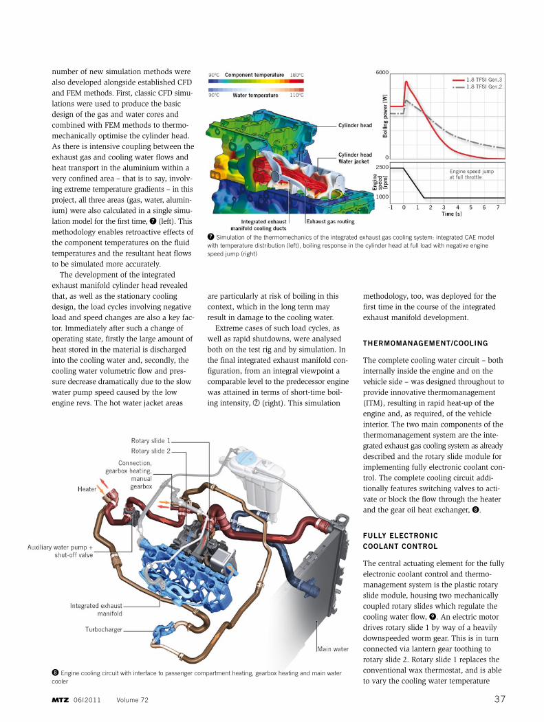
The complete cooling water circuit – both internally inside the engine and on the vehicle side – was designed throughout to provide innovative thermomanagement (ITM), resulting in rapid heat-up of the en gine and, as required, of the vehicle interior. The two main components of the thermomanagement system are the inte-grated exhaust gas cooling system as already described and the rotary slide module for implementing fully electronic coolant con-trol. The complete cooling circuit addi-tionally features switching valves to acti-vate or block the flow through the heater and the gear oil heat exchanger, ❽.
fully electronIc coolant control
The central actuating element for the fully electronic coolant control and thermo-management system is the plastic rotary slide module, housing two mechanically coupled rotary slides which regulate the cooling water flow, ❾. An electric motor drives rotary slide 1 by way of a heavily downspeeded worm gear. This is in turn connected via lantern gear toothing to rotary slide 2. Rotary slide 1 replaces the conventional wax thermostat, and is able to vary the cooling water temperature
❼ Simulation of the thermomechanics of the integrated exhaust gas cooling system: integrated CAE model with temperature distribution (left), boiling response in the cylinder head at full load with negative engine speed jump (right)
❽ Engine cooling circuit with interface to passenger compartment heating, gearbox heating and main water cooler
3706I2011 Volume 72
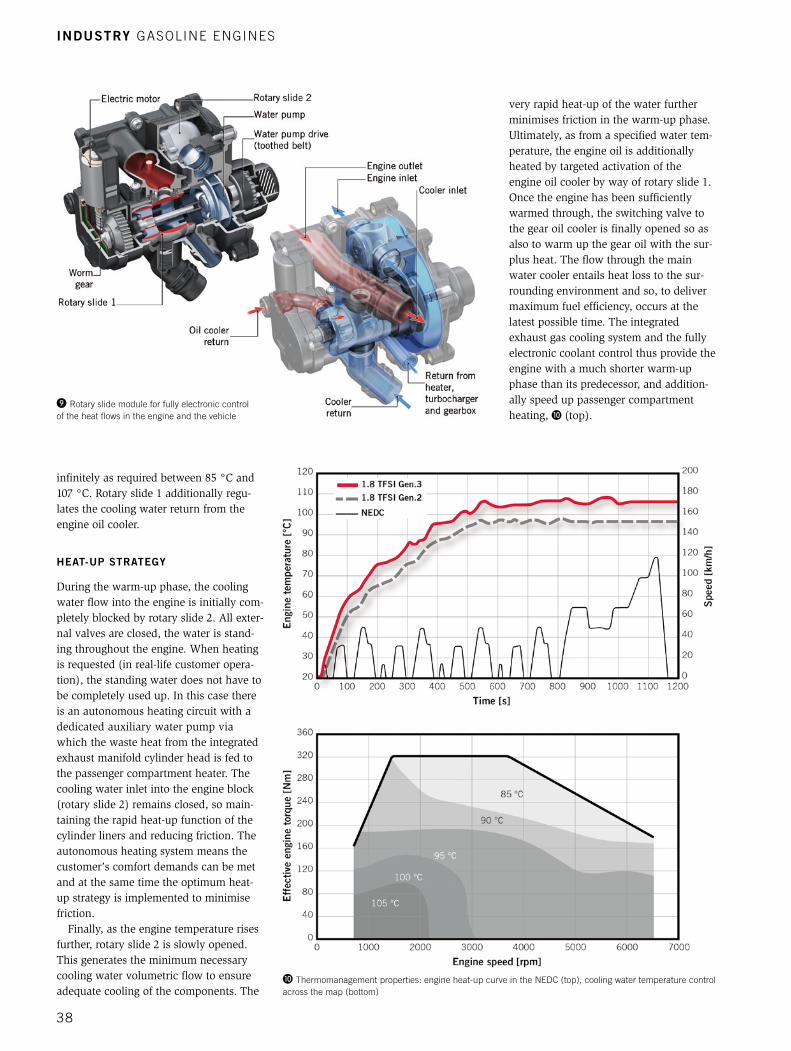
infinitely as required between 85 °C and 107 °C. Rotary slide 1 additionally regu-lates the cooling water return from the engine oil cooler.
heat-up strategy
During the warm-up phase, the cooling water flow into the engine is initially com-pletely blocked by rotary slide 2. All exter-nal valves are closed, the water is stand-ing throughout the engine. When heating is requested (in real-life customer opera-tion), the standing water does not have to be completely used up. In this case there is an autonomous heating circuit with a dedicated auxiliary water pump via which the waste heat from the integrated exhaust manifold cylinder head is fed to the passenger compartment heater. The cooling water inlet into the engine block (rotary slide 2) remains closed, so main-taining the rapid heat-up function of the cylinder liners and reducing friction. The autonomous heating system means the customer’s comfort demands can be met and at the same time the optimum heat-up strategy is implemented to minimise friction.
Finally, as the engine temperature rises further, rotary slide 2 is slowly opened. This generates the minimum necessary cooling water volumetric flow to ensure adequate cooling of the components. The
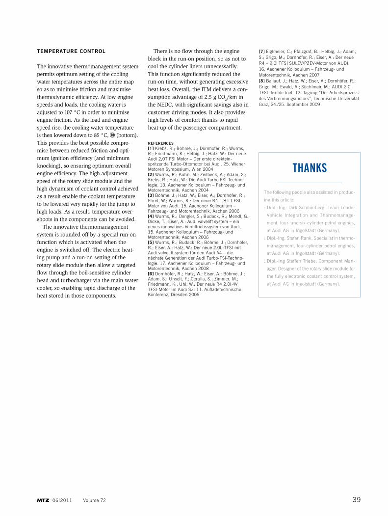
very rapid heat-up of the water further minimises friction in the warm-up phase. Ultimately, as from a specified water tem-perature, the engine oil is additionally heated by targeted activation of the engine oil cooler by way of rotary slide 1. Once the engine has been sufficiently warmed through, the switching valve to the gear oil cooler is finally opened so as also to warm up the gear oil with the sur-plus heat. The flow through the main water cooler entails heat loss to the sur-rounding environment and so, to deliver maximum fuel efficiency, occurs at the latest possible time. The integrated exhaust gas cooling system and the fully electronic coolant control thus provide the engine with a much shorter warm-up phase than its predecessor, and addition-ally speed up passenger compartment heating, ❿ (top).
❾ rotary slide module for fully electronic control of the heat flows in the engine and the vehicle
❿ Thermomanagement properties: engine heat-up curve in the nEDC (top), cooling water temperature control across the map (bottom)
Industry GASOlInE EnGInES
38
temperature control
The innovative thermomanagement system permits optimum setting of the cooling water temperatures across the entire map so as to minimise friction and maximise thermodynamic efficiency. At low engine speeds and loads, the cooling water is adjusted to 107 °C in order to minimise engine friction. As the load and engine speed rise, the cooling water temperature is then lowered down to 85 °C, ⑩ (bottom). This provides the best possible compro-mise between reduced friction and opti-mum ignition efficiency (and minimum knocking), so ensuring optimum overall engine efficiency. The high adjustment speed of the rotary slide module and the high dynamism of coolant control achieved as a result enable the coolant temperature to be lowered very rapidly for the jump to high loads. As a result, temperature over-shoots in the components can be avoided.
The innovative thermomanagement system is rounded off by a special run-on function which is activated when the engine is switched off. The electric heat-ing pump and a run-on setting of the rotary slide module then allow a targeted flow through the boil-sensitive cylinder head and turbocharger via the main water cooler, so enabling rapid discharge of the heat stored in those components.
There is no flow through the engine block in the run-on position, so as not to cool the cylinder liners unnecessarily. This function significantly reduced the run-on time, without generating excessive heat loss. Overall, the ITM delivers a con-sumption advantage of 2.5 g CO
2/km in the NEDC, with significant savings also in customer driving modes. It also provides high levels of comfort thanks to rapid heat-up of the passenger compartment.
references[1] Krebs, r.; Böhme, J.; Dornhöfer, r.; Wurms, r.; Friedmann, K.; Helbig, J.; Hatz, W.: Der neue Audi 2,0T FSI Motor – Der erste direktein-spritzende Turbo-Ottomotor bei Audi. 25. Wiener Motoren Symposium, Wien 2004[2] Wurms, r.; Kuhn, M.; Zeilbeck, A.; Adam, S.; Krebs, r.; Hatz, W.: Die Audi Turbo FSI Techno-logie. 13. Aachener Kolloquium – Fahrzeug- und Motorentechnik, Aachen 2004[3] Böhme, J.; Hatz, W.; Eiser, A.; Dornhöfer, r.; Ehret, W.; Wurms, r.: Der neue r4-1,8 l T-FSI- Motor von Audi. 15. Aachener Kolloquium – Fahrzeug- und Motorentechnik, Aachen 2006[4] Wurms, r.; Dengler, S.; Budack, r.; Mendl, G.; Dicke, T.; Eiser, A.: Audi valvelift system – ein neues innovatives Ventiltriebssystem von Audi. 15. Aachener Kolloquium – Fahrzeug- und Motorentechnik, Aachen 2006[5] Wurms, r.; Budack, r.; Böhme, J.; Dornhöfer, r.; Eiser, A.; Hatz, W.: Der neue 2.0l-TFSI mit Audi valvelift system für den Audi A4 – die nächste Generation der Audi Turbo-FSI-Techno-logie. 17. Aachener Kolloquium – Fahrzeug- und Motorentechnik, Aachen 2008[6] Dornhöfer, r.; Hatz, W.; Eiser, A.; Böhme, J.; Adam, S.; unselt, F.; Cerulla, S.; Zimmer, M.; Friedmann, K.; uhl, W.: Der neue r4 2,0l 4V TFSI-Motor im Audi S3. 11. Aufladetechnische Konferenz, Dresden 2006
[7] Eiglmeier, C.; Pfalzgraf, B.; Helbig, J.; Adam, S.; Grigo, M.; Dornhöfer, r.; Eiser, A.: Der neue r4 – 2,0l TFSI SulEV/PZEV-Motor von AuDI. 16. Aachener Kolloquium – Fahrzeug- und Motorentechnik, Aachen 2007[8] Ballauf, J.; Hatz, W.; Eiser, A.; Dornhöfer, r.; Grigo, M.; Ewald, A.; Stichlmeir, M.: AuDI 2.0l TFSI flexible fuel. 12. Tagung “Der Arbeitsprozess des Verbrennungsmotors”, Technische universität Graz, 24./25. September 2009
The following people also assisted in produc-
ing this article:
: Dipl.-Ing. Dirk Schöneberg, Team leader
Vehicle Integration and Thermomanage-
ment, four- and six-cylinder petrol engines,
at Audi AG in Ingolstadt (Germany).
: Dipl.-Ing. Stefan rank, Specialist in thermo-
management, four-cylinder petrol engines,
at Audi AG in Ingolstadt (Germany).
: Dipl.-Ing Steffen Triebe, Component Man-
ager, Designer of the rotary slide module for
the fully electronic coolant control system,
at Audi AG in Ingolstadt (Germany).
ThAnKS
3906I2011 Volume 72


