18771-2014-546-Rosecrans-final-1503 MMS TV Contamination ... · Contamination Summary Presenter:...
28
1 MMS Observatory Thermal Vacuum Results Contamination Summary Presenter: Glenn Rosecrans (SGT) Co-authors: Therese Errigo (NASA/GSFC) & Lubos Brieda (PIC-C) https://ntrs.nasa.gov/search.jsp?R=20150000220 2018-11-24T22:24:54+00:00Z
-
Upload
nguyendieu -
Category
Documents
-
view
215 -
download
0
Transcript of 18771-2014-546-Rosecrans-final-1503 MMS TV Contamination ... · Contamination Summary Presenter:...

1
MMS Observatory Thermal Vacuum ResultsContamination Summary
Presenter: Glenn Rosecrans (SGT)Co-authors: Therese Errigo (NASA/GSFC) &
Lubos Brieda (PIC-C)
https://ntrs.nasa.gov/search.jsp?R=20150000220 2018-11-24T22:24:54+00:00Z

2
MMS Observatory• Magnetospheric Multiscale (MMS) mission is a constellation of four (4)
identical observatories designed to investigate the fundamental plasma physics process of magnetic reconnection in the Earth’s magnetosphere.
The Instrument Suite (IS) on each observatory (OBS) consists of 27 instruments for plasma composition, fluxes of energetic particles, and electromagnetic fields
The detectors and charged particle focusing “optics” used for these measurements are sensitive to particulate and molecular contamination.
• The four observatories were individually subjected to thermal vacuum exposures in the Naval Research Laboratory’s (NRL) Big Blue (BB) refurbished chamber.
• A large clean room was constructed prior to TV testing, which helped stage TV preparatory activities for each OBS, outside the chamber.
• Dry runs with ground support equipment (GSE) were completed before actual OBS testing commenced. OBS testing started in November 2013 and concluded with OBS3 in early August 2014.- Picture of OBS before bagging for Acoustic testing,
- Uncovered Solar Arrays and Bay 7 thrusters- Mellinex covered IS along with some still red tag covered

3
OBS overview
Flight Passive Ring1 inch thick G 10 (nf)GSE Ring (nf)
Aeroflex Coil Springs (nf)1 inch thick G10 (nf)S Band Antennas (2)
Mag Booms, partially stowed(2)
Star Trackers (2)
Solar Arrays (8)
Thrusters, 6 each onBay 3 and 7
IS Deck (populated)
GPS antennas (8)
OSR covered shunts (4)nf non flight

4
Instrument Suite Components(View looking from the bottom of the IS deck)
• IS detect particles and field strengths based on voltage responses.Sensitive to voltage changes and electrostatic fieldsInstruments utilize microchannel plates (MCP), sensitive to molecular contamination, moisture, and conductive particles) and solid state detectors (SSD), sensitive to moisture
• 20 instruments and sensors shown on IS deck, out of 27 total.Instruments and supporting electronics came from Southwest Research Institute (SwRI), University of New Hampshire (UNH), and several other academia institutions

5
Thermal & Project Goals • General Environmental Verification Standard (GEVS) requires 4
complete cycles at OBS level.Thermally test and transition OBS Hot and Cold, after requested Bakeout.Check out operational and survival OBS heaters
• Use Hamster cage w/Cryopanels to control OBS thermallyBar heaters used to tweak temperature control for individual cryopanels.Cryopanels controlled by 4 new DynaVac Thermal Conditioning Units (TCU).
• Most electronic boxes have an A and B-side; needed to perform comprehensive tests (CPTs) under vacuum on all systems
Achieve 100 hours of operation time (powered on) in vacuum on each side• Special tests:
Achieve at least 9 hours of IS High Voltage time.Preconditioning OBS hardware/heaters for 4 hour eclipse.Mag Boom deployments (partial) with frangibolt activation.IS door deployments (EIS)Thruster valve operation and firings in hot and cold

6
TV test profile• OBS TV order was #2, #1, #4, and lastly #3.• OBS 2 started with a Thermal Balance with balance points, then chamber break
reconfigure/reset OBS subsystems and GSE, then complete 3 hot and cold thermal vacuum cycles.
Restarts required another (shortened) bakeout• OBS #1, #4, and #3 had then just 4 TV cycles, as pictured below• All observatories included hot and cold thruster fire test and high voltage testing

7
Test Configuration• Testing performed at Naval Research Laboratory using “Big Blue” chamber
Dedicated cleanroom was built encompassing chamber door and surrounding processing area
• Cold wall test, thermal cycling accomplished using thermal enclosure (“Hamster Cage”)
40 cryopanels for 6 thermal zones. TCUs, omega controllers, bar heaters. A lot of plumbing, required extensive leak checking.4 QCMs: 2 viewing IS (Bays 3&6), solar array (Bay 6), S/C vent (bay 2)
I/S Deckcontam barrier

8
Contamination Control Objectives • Complex set of CC objectives:
Bakeout and determination of BOL outgassing rates, maintaining molecular and particulate cleanliness, maintaining low pressure for H/V testing, monitoring thruster firing
• CC mitigations:Empty chamber precerts followed by dry runs with both “hamster cages”Contam/thermal barrier in HC, to separate IS from solar arraysDedicated Scavenger Plate (SP) ducted from OBS bus vent
• Used large chamber “Contam” Plate to retain most everything elsePrecleaned chamber before pumpdown and installed witness foilsMultiple repress cycles during pump down to drive off water vapor:
• Pumpdown and repress conducted as slow as possible to maintain stable environment (50 torr/hr to 200 torr, then 100 torr/hr to 500 torr)
Outgassing rate validated with 4 Quartz Crystal Microbalances (QCM).• Analysis generated goals to validate OBS outgassing rates.
16 Ion gauges (IG) to monitor pressure and also act as instrument sources• Needed <1E-6 Torr for 48 to 72 hours before IS High Voltage testing
Monitored thruster firing with Residual Gas Analyzer (RGA)

9
Pressure Monitoring• Utilized total of 19 ion gauges
Two existing chamber gauges (MKS and ion)One MMS provided gauge installed in chamber wall8 gauges outside the hamster cage to stimulate FPI DES/DIS1 gauge inside the HC as source for HPCA6 gauges inside the HC solely to monitor local pressure
• Brooks Series 355 ion gaugeCompact, small size, durable metal casing2 filaments, 3 current emission modes (low-vac, med-vac, high-vac)Had 2 sets of IG for each hamster cage (15 per cage).Manually controlled by Granville-Phillips Model 358 Micro-Ion controllersTested temperature response in a separate test, did not find any impact
• But to be safe, heaters used to maintain IGs above 0oC
Systems designed to autonomously trigger the High Voltage (HV) safingsignal for HV instruments at preset pressure levels and remain there until
manually reset.

10
Data Acquisition• TVAC controlled from GSFC, small core team supporting on site at NRL• TC, TQCM, and pressure data collected by NRL-developed CDACS
Python based GUI control and data acquisitionGSFC ASIST used to control spacecraft and obtain S/C and I/S telemetry
• MMS IT team instrumental in streaming data to GSFCThin clients allowed access to the same virtual terminal from GSFC or from NRL – many CC shifts supported remotely from GSFCStation screenshots posted to MMS I&T site every minute, allowed for remote monitoring during non-critical events (soak, waiting for thermal plateau…)
• CC team developed software for parsing CDACS and RGA log files
Having all TC, pressure, and TQCM data collected by the same DAQ greatly simplified anomaly investigations
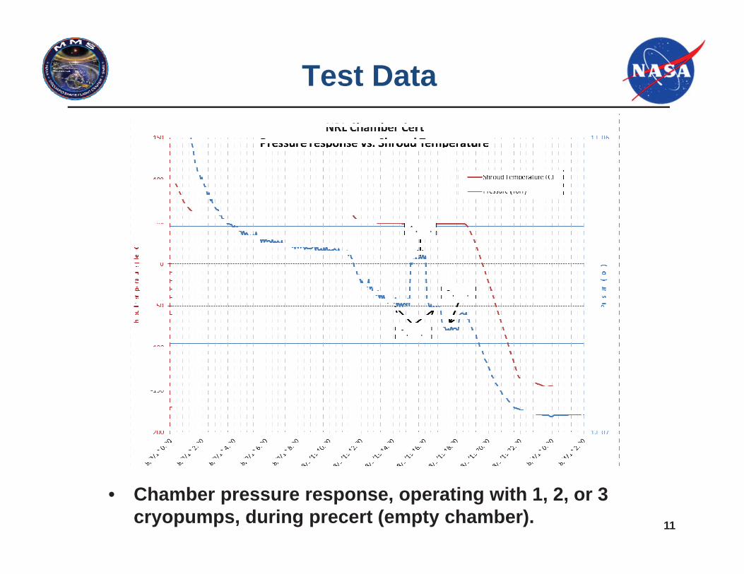
11
Test Data
• Chamber pressure response, operating with 1, 2, or 3 cryopumps, during precert (empty chamber).

12
TV pumpdown curve

13
Bakeout Phase• Why do a Bakeout (BO)?
To accelerate water vapor outgassing from OBS and GSE during prepReducing outgassing from added polymeric and epoxy materials on the OBS & GSE that still could outgas harmful chemical species to IS. Allocated 48 hours in test plan, but all TV times were shorter in duration.
• Flooded CP and SP first. • QCMs set to -20C, activated the RGA, and turned on couple IG• Once CP and SP < -120C, thermal then began to adjust HC
cryopanel settings up in 10C increments to 50C. Idea is to have the OBS hotter than the surrounding areaChamber Shrouds were also warmed up, but lagged cryopanels by 10C. Shrouds only got to 30-40C.
• Monitored BO with QCM and RGA. • QCM goals set based on meeting OGR of ~1E-12 g/cm2/sec.
Looked for meeting QCM delta frequency goals and achieving DDF <5 before calling it done.
• Perform 1st of thruster firings at end of BO

14
Bakeout PhasePressure response
Pressure initially dominated by water vapor
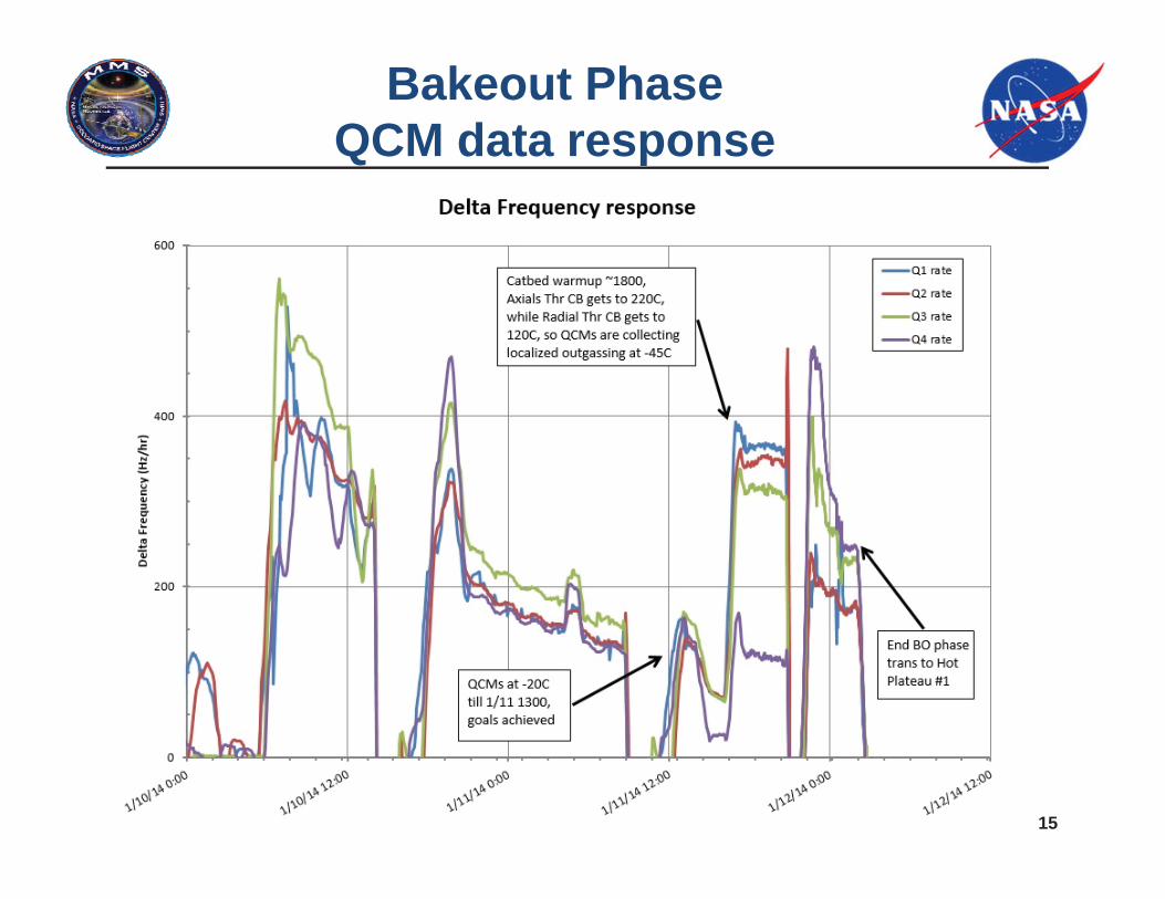
15
Bakeout PhaseQCM data response
16
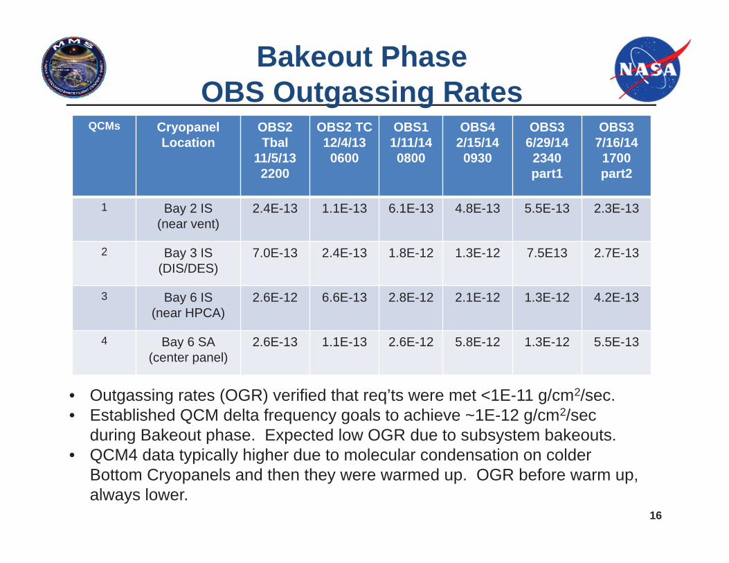
Bakeout PhaseOBS Outgassing Rates
QCMs CryopanelLocation
OBS2Tbal
11/5/13 2200
OBS2 TC12/4/130600
OBS11/11/14 0800
OBS42/15/140930
OBS36/29/142340part1
OBS37/16/141700part2
1 Bay 2 IS (near vent)
2.4E-13 1.1E-13 6.1E-13 4.8E-13 5.5E-13 2.3E-13
2 Bay 3 IS(DIS/DES)
7.0E-13 2.4E-13 1.8E-12 1.3E-12 7.5E13 2.7E-13
3 Bay 6 IS(near HPCA)
2.6E-12 6.6E-13 2.8E-12 2.1E-12 1.3E-12 4.2E-13
4 Bay 6 SA(center panel)
2.6E-13 1.1E-13 2.6E-12 5.8E-12 1.3E-12 5.5E-13
• Outgassing rates (OGR) verified that req’ts were met <1E-11 g/cm2/sec.• Established QCM delta frequency goals to achieve ~1E-12 g/cm2/sec
during Bakeout phase. Expected low OGR due to subsystem bakeouts.• QCM4 data typically higher due to molecular condensation on colder
Bottom Cryopanels and then they were warmed up. OGR before warm up, always lower.

17
Thruster firing• Propulsion group tested response of 4 axial and 8 radial thrusters by firing each for
~ 50 milliseconds at hot and at cold plateauTanks filled with GN2 (28 amu) with argon (40 amu) tracer, no hydrazine CC not necessarily concerned from actual gas depositing onto IS surfaces from thruster firings but it was “deemed good” being hot biased initially. Main concern with catbed activations – reaches 220C for axial and 120C for radial thrusters. The localized polymeric and epoxy material could outgas significantly during this preparation for thruster firings. Performed with A-side and B-side CDH and PSE ebox activation, separated by 2-3 hours in TV.
• Critical to avoid helium and purge all prop lines due to lack of turbo pump. Cryopumps have very limited Helium pumping capacity!
• Prop testing monitored byCC with RGA switched to pressure vs. time mode
Pulses corresponding to thruster firing Also monitored Helium
1.1E-6
3.4E-6

18
Thruster firingPressure and TQCM response

19
OBS Thermal Transitions• CC Monitoring during thermal transitions critical
Desired to maintain <1E-6 Torr at all time to avoid resetting timer for H/V testing• Necessitated slow transition rates and maintaining > -90C

20
Ion Gauge response
1E-6 torr
1.4E-6 torr
6E-7 torr

21
Ion Gauge responseHot Plateau to Cold Plateau

22
OBS WarmUp in Stages

23
OBS1 Thermal cyclepressure levels
Started January 9, 2014Ended February 2, 2014
MIGs 1 & 2 external to HCMIGs 3-6 are internal to HC

24
OBS3 TV issues• Elevated High pressure levels from start of TVac to almost finish!• How to remove Helium and Nitrogen from chamber?
Performed numerous Cryopump regenerations and even tried cycle purgingEliminated Prop tanks from being the source of either gas
• No partial pressure gains from Thruster firings and analytically ruled outBackfilled to 100 torr, did NOT reduce HeliumLeak checked with Argon, nothing really noticed consistentlyBackfilled to ambient pressure; installed “cobbled” Turbo Pump setup (Webb)
• Helium now successfully removed (not by TP though), but now high levels N2 Decided to run with all 3 Cryopumps open; held just 1E-6 torr in Cold PlateauThermal minimizes temperature changes, minimum Cryopanels to -85C
• IS team nervously goes forth with HV testing and completesRealized that manual vent valves for CP, QCMs, SP discharge were all closed (from leak testing)
• Opened and relieved back pressure through cryo flex lines, pressure stabilizes..• Until they freeze over. Needed to melt iceball (Tooley with blow torch)

25
Other OBS3 TV issues• Were we in the clear? Barely, proceeded to settings for Eclipse
Preheated OBS, then all Chamber shrouds & cryopanels were flooded w/LN2Momentary large pressure spike to 1.2E-5 and then all quiet! The Big Freeze appears to seal all the leaks & reseats chamber burst diskPressure holds <4 E-7 torr for remainder of testing.
Other test support apparatus failed during testing as wellSolenoids became stuck at various times
• Initially in checkout with Omega 10, controlling Bottom ring cryopanel, became SP!• The later again later when in Cold Plateau #4, PL melts iceball w/torch
TCU #3 failed early, middle, and wasn’t used much after that, until Eclipse• Trip a circuit breaker, set off alarms, purge line left open during pre-TV checkout• Boom (heard at NRL) relief disk burst, in-line supply too fast (5C/min vs. 1C/min)• Found to be a source of N2 leaks, taken off line. Rough pump attached to it for
days. Thermal uses heater bar control for Solar Array temperature control.
• Project polled IS and OBS near end of CP#4. Nobody wanted to conduct any additional testing (even though pressure issues seemed resolved) so the TV test ended without anymore issues.

26
OBS3 Thermal cyclepressure levels
Started June 27, 2014Ended July 14, 2014 am Part 1
ReStarted July 14, 2014 pmEnded July 31, 2014 Part 2
MIGs 1, 2, &15 external to HCMIGs 3-6 are internal to HC

27
OBS3 Pressure “Relief”

28
Lessons Learned• After 4 TV tests, we still didn’t capture every step, recall every
chamber operating nuance to make the TV tests go 100% smoothly. • Very complex setup, tight confines, lots of mechanical and thermal
hookups required. Leak checked every time, perhaps too much Helium used in progress. Consider using Argon as well.
• Operated TCUs in ambient temperature and still couldn’t detect all the connection leaks. Figure better way to detect leaks.
• Certainly Need vacuum to validate operation of chamber systems beforehand; during Dry Runs & precerts.
• Don’t turn off Observatory heaters too soon. Needed to maintain OBS warmer than surrounding panels and GSE.
• Ion gauges were ideal for protecting IS from exposures to pressure spikes during HV operations.
• Real-time monitoring, shift test logging, and cross training project personnel has it’s benefits.
• Expect to have problems. Have backup safety plans to secure HW.