18728B T Bones - Bike Racks & Bike Trainers | Saris · per bike weight of 35lbs.) on carrier....
8
FINALLY – A COMPANY THAT LOVES BIKES AS MUCH AS YOU DO. Chances are, your bikes are just like ours - your most valued possessions. And if it has the Saris name on it, nothing we build goes out the door unless it’s worth putting those possessions on. Call it obsessive. Call it eccentric. We just chalk it up to caring a hell of a lot about creating the last rack you’ll ever need. T-Bones Installation Instructions T-Bones 2 Bike #812 T-Bones 3 Bike #813 TONGUE WEIGHT LIMITATIONS *35lbs/bike maximum Hitch Tongue Weight Maximum Load Models 1 1/4” & 2” 200lbs 2 bikes/70 lbs* 812 3 bikes/105 lbs* 813 Tools Needed: ¾” (19mm) wrench Phillips screwdriver 4mm hex wrench (included) 1. PARTS INCLUDED 2 1 3 4 5 18 20 14 15 16 17 13 12 11 10 9 7 8 6 21 Item Description QTY 1 T-Bones Rack 1 2 T-Bones Transport Bag 1 3 T-Bones Stand Leg, Left 1 4 T-Bones Stand Leg, Right 1 5 T-Bones Stand Tower Halves 2 6 Quad Fit Hitch Receiver Tube 1 7 Receiver Cover, Passenger Side 1 8 Receiver Cover, Driver Side 1 9 Plastic Hitch Tite 1 10 2” Adapter 1 11 Hitch Lock 1 12 Hex Nut, 5mm 4 13 Socket Head Bolt, 5mm 4 14 4mm hex wrench 1 15 Locking Hitch Pin, Threaded 1 16 Lock Washer 1 17 Hex Nut, 3/4” 1 18 Hex Nut, 8mm 4 19 Square Nut, 8mm 2 20 Socket Head Bolt, 8mm 5 21 Key 2 22 Self Tapping Screw 2 Record Key# Rack instructional video available at http://www.saris.com/p-370-t-bones.aspx 19 22
Transcript of 18728B T Bones - Bike Racks & Bike Trainers | Saris · per bike weight of 35lbs.) on carrier....

FINALLY – A COMPANY THAT LOVES BIKES AS MUCH AS YOU DO.
Chances are, your bikes are just like ours - your most valued possessions. And if it has the Saris name on it, nothing we build goes out the door unless it’s worth putting those possessions on. Call it obsessive. Call it eccentric. We just chalk it up to caring a hell of a lot about creating the last rack you’ll ever need.
T-BonesInstallation Instructions
T-Bones 2 Bike #812
T-Bones 3 Bike #813
TONGUE WEIGHT LIMITATIONS *35lbs/bike maximum
Hitch Tongue Weight Maximum Load Models1 1/4” & 2” 200lbs 2 bikes/70 lbs* 812 3 bikes/105 lbs* 813
Tools Needed:¾” (19mm) wrench Phillips screwdriver4mm hex wrench (included)
1. PARTS INCLUDED
2
1
3 4
5
18
20
14
15
16
17
13 12
11
10
9
7 8
6
21
Item Description QTY
1 T-Bones Rack 1
2 T-Bones Transport Bag 1
3 T-Bones Stand Leg, Left 1
4 T-Bones Stand Leg, Right 1
5 T-Bones Stand Tower Halves 2
6 Quad Fit Hitch Receiver Tube 1
7 Receiver Cover, Passenger Side 1
8 Receiver Cover, Driver Side 1
9 Plastic Hitch Tite 1
10 2” Adapter 1
11 Hitch Lock 1
12 Hex Nut, 5mm 4
13 Socket Head Bolt, 5mm 4
14 4mm hex wrench 1
15 Locking Hitch Pin, Threaded 1
16 Lock Washer 1
17 Hex Nut, 3/4” 1
18 Hex Nut, 8mm 4
19 Square Nut, 8mm 2
20 Socket Head Bolt, 8mm 5
21 Key 2
22 Self Tapping Screw 2
Record Key#
Rack instructional video available at http://www.saris.com/p-370-t-bones.aspx
19
22

2. CHOOSE YOUR SETUP
x= 6¼” (16cm)y= 13¼” (35cm)
x= 10¼” (26cm)y= 9¼” (23.5cm)
Extended FitFor spare tire clearance.Recessed hitches.
Compact FitFits closer to the vehicle.Improves ground clearance.
x
x
y
y
Quad Fit Hitch Base
Determine size of receiver hitch on vehicle.
2” Receiver 1 - 1/4” Receiver
Determine desired set back and clearance.
Tailgate Caution Hatch Caution Spare Tire Caution
Attention! Avoid vehicle to hitch contact. Some examples below.
A
B

1 - 1/4” RECEIVER ONLY
Hitch Base Assembly
ABC 123
Press 8mm and ¾" nuts into plastic hitch tite.
Press hitch tite into receiver as illustrated Slide receiver into 1¼" hitch as illus-trated. Install threaded hitch pin bolt and lock washer fully tighten using ¾” (19mm) wrench.
Installation of rack to vehicle
2 Holes
Slide hitch lock body onto hitch pin bolt to engage and install cover as illustrated. Note: pull on lock body to ensure engage-ment!
8mm¾"
Install 2" adapter bolt and fully tight-en using 4mm hex wrench provided.
Slide hitch 2" adapter onto receiver.
Small hole
3. ASSEMBLY/INSTALLATION - Receiver specific. Follow your receiver type only.
A B C
2” RECEIVER ONLY
Hitch Base Assembly
Press 8mm and ¾" nuts into plastic hitch tite.
Press hitch tite into receiver as illustrated
2 Holes8mm¾"
A B
D
C
Slide hitch lock body onto hitch pin bolt to engage and install cover as illustrated. Note: pull on lock body to ensure engagement!
ED F
Slide receiver into 2" hitch as illustrated. In-stall threaded hitch pin bolt and lock washer fully tighten using ¾” (19mm) wrench.

There are three positions on the release handle: release, neutral and closed.
1. Position the quick release handle in the “Neutral” position. Note: When handle is pulled free from the “Closed” position the handle will rest at the “Neutral” position.
2. Slide the rack over the receiver covers on the hitch base assembly as illustrated. You will hear two clicks!3. Push the lever to the “Closed” position.4. Insert key into lock cylinder and turn to locked position. Remove key.
TECH TIP: Freqeuently lubricate locks using a synthetic based oil.
Quick Dock Lever
Release
Neutral“Install”
Closed
Unlocked Position Locked Position
Rear View
Install receiver covers on receiver tube with 4mm fasteners as illustrated. Note: orientation of receiver covers.
Fully tighten all fasteners with the 4mm hex wrench provided.
Fully tighten
4. RECEIVER COVER INSTALLATION
B
5. QUICK DOCK LEVER USAGE
A
Separate the receiver covers.
A C
Receiver boss
LargeReceiverHole
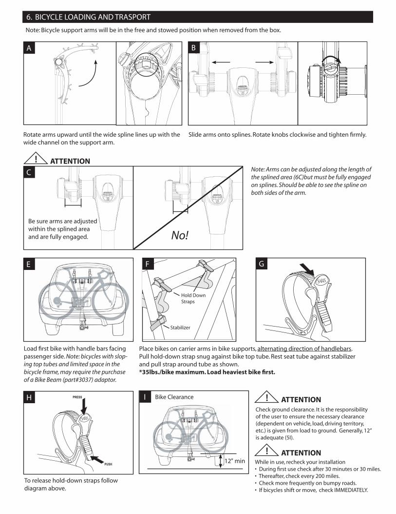
Load fi rst bike with handle bars facing passenger side. Note: bicycles with slop-ing top tubes and limited space in the bicycle frame, may require the purchase of a Bike Beam (part#3037) adaptor.
R
Place bikes on carrier arms in bike supports, alternating direction of handlebars. Pull hold-down strap snug against bike top tube. Rest seat tube against stabilizer and pull strap around tube as shown.*35lbs./bike maximum. Load heaviest bike fi rst.
Hold Down Straps
Stabilizer
Rotate arms upward until the wide spline lines up with the wide channel on the support arm.
Note: Bicycle support arms will be in the free and stowed position when removed from the box.
Slide arms onto splines. Rotate knobs clockwise and tighten fi rmly.
Be sure arms are adjusted within the splined area and are fully engaged.
7
6. BICYCLE LOADING AND TRASPORT
A B
C
R
To release hold-down straps follow diagram above.
E F G
H
12" min
Bike Clearance
While in use, recheck your installation• During fi rst use check after 30 minutes or 30 miles.• Thereafter, check every 200 miles.• Check more frequently on bumpy roads.• If bicycles shift or move, check IMMEDIATELY.
Check ground clearance. It is the responsibility of the user to ensure the necessary clearance (dependent on vehicle, load, driving territory, etc.) is given from load to ground. Generally, 12” is adequate (5I).
! ATTENTION
! ATTENTION
I
! ATTENTIONNote: Arms can be adjusted along the length of the splined area (6C)but must be fully engaged on splines. Should be able to see the spline on both sides of the arm.
No!

With bicycles unloaded!1. Loosen knobs one full turn and fold arms down.2. Slide arms on to splines and tighten knobs.3. Unlock handle using key.4. Lift lever to “Release” position with one hand and simultaneously pull up on
aluminum tube with the other to release rack from hitch base.
Quick Dock Lever
Release
Neutral
Closed
1. Pull lock from lock basket.2. Insert key into lock cylinder and turn to unlocked position to open lock.3. Remove key4. Feed one end of lock cable through bicycle frame(s) and the other over the top of
the bicycle(s) as illustrated.5. Insert cable end into lock body as illustrated to engage lock.6. Reverse order to stow lock. Note: lock both cables together for storage and feed
cable into lock basket with both hands.
Bicycle Security
Locked Unlocked
J
7. DETATCHMENT OF RACK FROM VEHICLE
8. ASSEMBLY OF STORAGE T-STAND
Slide right and left bottom stand bases together as shown.
Turn stand over. Install two 8mm bolts and square nuts as shown and tighten by hand.
Return stand to upright position. Press right and left upper tower together. Slide tower stand assembly into the lower stand assembly.
Push
A
A B C
Push the upper and lower stand assem-blies together applying equal pressure to the parts. Install two 8mm bolt and nut as shown on tower assembly and tighten fasteners firmly using the 4mm hex wrench as illustrated.
Turn stand over and install 8mm fastener and nut.Tighten all 5 fasteners firmly using the 4mm hex wrench.
Rest stand on floor or table as shown to install screws. Using a Philips screwdriver, install two self tapping screws as shown. Tighten fully.
D EF
+ +

B. Removal
1. Unload bicycles.2. Unlock handle using key.3. Lift lever to “Release” position with one hand and pull up on aluminum tube with the other hand at the same time to release
rack from stand.
9. INSTALLATION AND REMOVAL OF RACK TO STAND
There are three positions on the release handle: release, neutral and closed.
A. Installation
1. Position the quick release handle in the “Neutral” position. Note: When handle is pulled free from the “Closed” position the handle will rest at the “Neutral” position.
2. Slide the rack over the T-Stand tower as illustrated. You will hear two clicks!3. Push the lever to the “Closed” position.4. Rotate arms to upright position.5. For bicycle loading see “Bicycle Loading and Transport”
Release
Neutral“Install”
Closed
Rear ViewA
Loosen compression straps and discon-nect compression strap on zipper side, then open zipper.
Insert rack in the upside down orienta-tion with the handle in neutral position.If desired – load shoes in the side pock-ets and insert helmet in the pouch as illustrated.
Loosen straps
Disconnect strap
10. INSTALLING RACK IN BAG
A B
Tighten compression straps as illustrated.
C
Place transport bag over shoulder as illustrated for transport.
Adjust strapas needed
D

Saris Cycling Group, Inc. 5253 Verona Road, Madison WI 53711 800.783.7257 www.saris.com 18728B 01/11 Patents Issued and Pending.
CAUTIONS / WARNING AND DISCLAIMER / WARRANTY
CAUTIONS: 1) All requirements for compatability/fit as stated in the current Saris vehicle/carrier compatability guide must be followed. (Available at any Saris dealer). If your vehicle is not listed or you have any questions, please call our customer service at 800-783-7257.2) Rack should be locked to vehicle at all times.3) Rack is not intended for use with tandem or recumbent bicycles.4) Read and follow instructions carefully. Save intallation manual for future reference or parts information.5) Inspect rack prior to each use for wear or broken parts. Replacement parts are available through your local Saris dealer or call 1-800-783-7257.6) Make sure bike tires are not directly behind exhaust pipe.7) Never place more than three bicycles (maximum per bike weight of 35lbs.) on carrier. Secure properly and adjust for even load distribution.8) Do not mount to any type of trailer.9) Do not open rear deck (trunk) with carrier installed.10) This carrier is not recommended for off-road use or for use at speed exceeding 65 mph.11) Remove carrier from vehicle when not in use.12) When cleaning rack, use only water soluble cleaners. Do not take rack through car wash.13) It’s the end users responsibility to ensure that use of this product meets all local and state laws.14) To prevent potential damage, secure the front tires of bicycles (part number 3033 recommended).
WARNING AND DISCLAIMER: This carrier has been designed to carry bicycles on specific vehicles. Before installation, user must read and follow current Saris Fit Guide (available through Saris dealer) recommendations and enclosed instructions. Fit recommendations are based on vehicle’s standard features; optional features may affect the fit recommendations. User must attach carrier correctly to the vehicle, check its attachment before each use, and inspect carrier parts for wear. Carrier’s attachment to the vehicle is critical and beyond the control of the manufacturer. Manufacturer and seller expressly disclaim any and all liability for personal injury, property damage or loss, whether direct, indirect, or incidental, resulting from the incorrect attach-ment, improper use, inadequate maintenance, or neglect of this carrier.
WARRANTY: Saris Cycling Group, Inc. (“Saris”) warrants that your Saris product will be free from defects in materials and workmanship for as long as you own the product. This warranty only extends to the original con-sumer buyer. This warranty does not apply to parts that have worn out through normal use or been dam-aged through misuse, abuse, neglect, accident or unauthorized modifications.ANY IMPLIED WARRANTIES WHICH THE BUYER MAY HAVE ARE LIMITED IN DURATION TO THE TIME THAT THE ORIGINAL CONSUMER BUYER OWNS THE PRODUCT. Some states do not allow limitations on how long an implied warranty lasts, so the above limitation may not apply to you. At its option, Saris will repair or replace, or refund the purchase price of, any Saris product which is defective or fails to conform with this warranty under normal use and service. To obtain service under this warranty, return the defective Saris Product or part, freight prepaid, to Saris at the address below. Please contact our customer service department prior to return to get a return authorization number. Repair or replacement of a defective Saris product or refund of the purchase price, shall be the sole remedy of the buyer under this warranty, and in no event shall Saris be liable for incidental or consequential damages, losses or expenses. Some states do not allow the exclusion or limitation of incidental or consequential damages, so the above limitation or exclusion may not apply to you.This warranty gives you specific legal rights, and you may also have other rights which vary from state to state.