1833 Downs Drive West Chicago, IL 60185...West Chicago, IL 60185 1833 Downs Drive INS094 Revised...
2
e-mail: [email protected] We want to help! If you have any comments or difficulty with this product, please contact technical support at FIGURE 1 INSTRUCTION SHEET Chrysler Performance Alternators 7508, 7509, 17508, 175081, 17509, 175091, 17519, 175191 INSTALLATION These instructions are provided as supplementary information to the factory service manual instructions for alternator replacment. DISCONNECT THE BATTERY. REMOVE THE OLD ALTERNATOR. See the fac- tory service manual for more details. Be sure to label all wires before removing to assure proper reinstallation and location. INSTALL THE NEW ALTERNATOR. ♦ Mount the alternator and check for interference with the brackets or other engine components. Start the bolts but do not tighten them at this time. ♦ Check for proper belt alignment. Adjust belt tension and tighten belt tension bolt as illustrated in Figure 1. Do not use heavy tools to pry on alternator case; hand pressure is adequate. Tension the belt to the engine manufacture’s specification. This is typically half an inch of deflection. ♦ Tighten all other bolts. ♦ Reconnect all wires and check labeling for correct location. If Powermaster alternator is of a higher amperage that the alternator that came OE on the vehicle then Powermaster recommends upgrading the battery output cable from the alternator. Your local speed shop has optional charge wires for this purpose. ♦ Note that the Powermaster alternator is a double field unit that will work with both double field and single field type external regulators. If your vehicle has two small field wires, they should be connected to the FLD terminals on the back of the alternator. These wires are interchangeable, so either wire can be connected to either FLD terminal. If your vehicle has one small field wire, connect it to either FLD terminal on the alternator. Then, using a short 16 AWG or larger jumper wire, ground the remaining FLD terminal. Some models have a ground stud on the back alternator case; this or any other bare metal grounding point will be sufficient. CONNECT THE BATTERY. PLEASE KEEP IN MIND... • ALWAYS wear eye protection when working around batteries. • ALWAYS disconnect battery ground terminal and cable assembly be- fore replacing electrical components. • NEVER disconnect a battery cable or alternator cable and wires when engine is running. Transient voltages (spikes) are produced when this occurs and some of these voltages exceed 200 volts. This can cause alternator voltage regulator or engine computer failure. • AVOID short circuits. When working with live circuits, never jumper between terminals or from terminals to ground, nor try to trouble shoot by "sparking" terminals. Always use a quality voltmeter to check the operation of live circuits. • CHECK the battery. Alternators and batteries work together. It is important that the battery be in good condition and fully charged when replacing the alternator. Do use an alternator to charge a dead battery. (800) 862-7223 West Chicago, IL 60185 1833 Downs Drive INS094 Revised 8/16/10
Transcript of 1833 Downs Drive West Chicago, IL 60185...West Chicago, IL 60185 1833 Downs Drive INS094 Revised...
e-mail: [email protected]
We want to help! If you have any comments or difficultywith this product, please contact technical support at
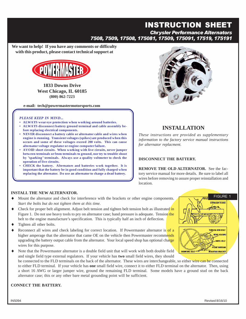
FIGURE 1
INSTRUCTION SHEET
Chrysler Performance Alternators
7508, 7509, 17508, 175081, 17509, 175091, 17519, 175191
INSTALLATIONThese instructions are provided as supplementaryinformation to the factory service manual instructionsfor alternator replacment.
DISCONNECT THE BATTERY.
REMOVE THE OLD ALTERNATOR. See the fac-tory service manual for more details. Be sure to label allwires before removing to assure proper reinstallation andlocation.
INSTALL THE NEW ALTERNATOR.♦ Mount the alternator and check for interference with the brackets or other engine components.
Start the bolts but do not tighten them at this time.♦ Check for proper belt alignment. Adjust belt tension and tighten belt tension bolt as illustrated in
Figure 1. Do not use heavy tools to pry on alternator case; hand pressure is adequate. Tension thebelt to the engine manufacture’s specification. This is typically half an inch of deflection.
♦ Tighten all other bolts.
♦ Reconnect all wires and check labeling for correct location. If Powermaster alternator is of ahigher amperage that the alternator that came OE on the vehicle then Powermaster recommendsupgrading the battery output cable from the alternator. Your local speed shop has optional chargewires for this purpose.
♦ Note that the Powermaster alternator is a double field unit that will work with both double fieldand single field type external regulators. If your vehicle has two small field wires, they shouldbe connected to the FLD terminals on the back of the alternator. These wires are interchangeable, so either wire can be connectedto either FLD terminal. If your vehicle has one small field wire, connect it to either FLD terminal on the alternator. Then, usinga short 16 AWG or larger jumper wire, ground the remaining FLD terminal. Some models have a ground stud on the backalternator case; this or any other bare metal grounding point will be sufficient.
CONNECT THE BATTERY.
PLEASE KEEP IN MIND...• ALWAYS wear eye protection when working around batteries.• ALWAYS disconnect battery ground terminal and cable assembly be-
fore replacing electrical components.• NEVER disconnect a battery cable or alternator cable and wires when
engine is running. Transient voltages (spikes) are produced when thisoccurs and some of these voltages exceed 200 volts. This can causealternator voltage regulator or engine computer failure.
• AVOID short circuits. When working with live circuits, never jumperbetween terminals or from terminals to ground, nor try to trouble shootby "sparking" terminals. Always use a quality voltmeter to check theoperation of live circuits.
• CHECK the battery. Alternators and batteries work together. It isimportant that the battery be in good condition and fully charged whenreplacing the alternator. Do use an alternator to charge a dead battery.
(800) 862-7223West Chicago, IL 60185
1833 Downs Drive
INS094 Revised 8/16/10

SYSTEM CHECK♦ Apply a moderate load to the charging system (i.e., high beam headlights and A/C for example) and
bring the engine to 1,500rpm. Using a digital voltmeter measure the DC voltage from the a baremetal point on the case of the alternator to the negative battery terminal. Readings higher than0.10VDC indicate a poor ground connection. Check the ground path including any paint or anod-izing on the brackets, the engine ground strap, and the ground cable from the frame to the battery.(See figure 2).
♦ With battery fully charged and engine running at 1,500rpm, measure the voltage at battery positivepost (+) and the ground post (-). Voltage should be 13.8~14.5VDC. Readings above 15.5VDC
indicate a defective alternator and readings below 12.7VDC indicate thatthe alternator is not functioning or cannot supply the current amperageneeds of the vehicle at this engine speed.
♦ Using the voltmeter, measure the voltage drop between the batty positive post (+) and the alternatoroutput post (See figure 3). Voltage should be less that 0.40VDC. If voltage is higher that 0.40VDC,check for poor connections between the alternator and the battery. Possible causes are unsized batterycables, loose or improperly crimped terminals, and corroded connections.
FIGURE 2
FIGURE 3
Why is my voltage low when I’m cruising around at a show or sitting at a traffic light?All alternators have an output curve that increases with RPM. In other words, your alternator cannot provide as many amps atidle as it can at higher speeds. If you car demands more amperage than the alternator can supply at idle, the remaining ampsmust come from the battery thus a decrease in voltage results. Any after market pulleys that slow the alternator relative to theengine [i.e. power pulleys] can greatly magnify this problem.
Why does my voltage test good at the alternator but low at the battery and fuse box?Any resistance in the electrical path will decrease voltage. This includes all positive and negative conductors and connectionsbetween the alternator and the second test point. All connections must be secure and free of corrosion. All ground points mustbe free of paint and rust. Charging wires must be of adequate size for the amperage capabilities of your alternator. Improvingany weak points in the electrical paths should bring voltage readings to within 0.5 volts of each other.
Battery charge wires- Powermaster recommends that a 10 AWG or largerbattery charge wire be used with all 75 amp alternators. If the battery hasbeen relocated to the trunk, a 6 AWG or larger charge wire is required tocompensate for the longer distance.
Square & round back type alternators- Early Mopar round back alternatorscan be upgraded to the later square back style unit. Both types have thesame mounting and basic wiring configuration. High amperage and chromeare available only in the square back design.
Aftermarket pulleys- The Mopar alternator design uses a pressed on pulley.Special tools are required to prevent alternator damage when removing andreinstalling the pulley. The unit should also be disassembled when the pulleyis being installed to prevent damage to the bearings and brush holders. Forthese reasons, it is recommended that a professional alternator shop installaftermarket pulleys.
External regulators- The alternator’s voltage output is controlled by theexternal regulator. It is recommended when replacing an alternator that theexternal regulator also be replaced.