
180A POWER SYSTEM Hampden’s H-180 Power System Simulator ... Power System... · Hampden’s H-180...
15
Hampden Engineering Corporation The World Leader in Teaching Equipment The World Leader in Teaching Equipment 180A POWER SYSTEM 180A POWER SYSTEM SIMULATOR SIMULATOR State of the Art State of the Art in the Industry in the Industry
Transcript of 180A POWER SYSTEM Hampden’s H-180 Power System Simulator ... Power System... · Hampden’s H-180...

99 Shaker Road P.O. Box 563, East Longmeadow, MA 01028-0563 • TEL. (413) 525-3981 • (888) HEC-CORP • FAX (413) 525-4741
Hampden Engineering Corporation
Hampden is committed to providing industry-leading technology.
For the latest from Hampden, visit our home page at http://www.hampden.com or e-mail us at [email protected]
100616
S C A D A S C A D A ( S( S U P E R V I S O R YU P E R V I S O R Y CC O N T R O LO N T R O L A N DA N D DD A T AA T A AA Q U I S I T I O NQ U I S I T I O N ))
Hampden Engineering CorporationT h e W o r l d L e a d e r i n T e a c h i n g E q u i p m e n tT h e W o r l d L e a d e r i n T e a c h i n g E q u i p m e n t
180A POWER SYSTEM 180A POWER SYSTEM SIMULATORSIMULATOR
GREEN
MECHANICAL
CO U N C I
L
SCADA FOR H-180 POWER SYSTEM SIMULATOR
The term SCADA was first used in the early 1960’s for data collec-tion in a variety of industrial processes. Today, we use a computer,PLC (Programmable Logic Controller), or RTU (Remote TerminalUnit) for gathering and analyzing real time data.
Hampden’s H-180 Power System Simulator utilizes SCADA to con-trol and display data through customizable built-in programmablecontrollers and a customizable HMI (Human-Machine Interface).
Figure #1: Hampden Engineering Corporations Power System Simulator
The SCADA system monitors power and controls power relays andequipment. It collects process data and displays real time data asit occurs. The data is analyzed to determine where relays havetripped on power lines, then central control is alerted that a faulthas occurred, and control procedures are implemented, such as, reclosing a faulted breaker to determine if the fault is critical. Thedata is then stored and recorded in history files stored in individualRTU’s.
Hampden’s H-180 Power System Simulator is fully functional whenpower is turned on. The simulator has its own controllers/proces-sors monitoring and recording data. When the supervisor connectsthrough the network all data can be monitored and controlled viathe simulators HMI.
Each section of the simulator screen has a detail button which canbe accessed to reveal a detailed description of the section.
Figure #2: H-180 Power Simulator Section 1 bottom detail screen
The many connected devices feed real time data to the trainer’scontroller which immediately acts on the data. Information is updated, adjusted and displayed as it happens. Accurate power information is obtained and displayed such as power consumptiondata displayed in Figure #3.
Figure #3: H-180 Power Meter 1 Detail Screen
Data is collected and stored in several devices for later historicalretrieval. But real-time events and current readings are displayed ina general table format for all devices(Figure#4)
Figure#4: H-180 Generator 1 readings table for SEL-751-1.
State of the ArtState of the Art
in the Industryin the Industry

GENERALThe essence of all operations are modeled on a typical central station utility. Basic system operations include:
• Time
• Diversity of Loads
• Multiple Sources of Generation
• Interconnection of Systems
Understanding of these concepts is necessary for any successful presentation or study of basic central station utility systems, and also form the basis for the design and developmentof new sources of reliable power.
The control panel of Hampden’s Power System Simulator has beendesigned to provide full functionality and control for the followingoperational factors:
1. LOADS
The panel includes simulations for constantly varying levels of consumer loads including; industrial, commercial, residential, andstreet lighting requirements.
The primary element of time is introduced, for example; daytime industrial loads, evening commercial applications, 24-hour residential utilizations, and street lighting. The standard time cyclehas been compressed so that a 2 hour real-time session will include a complete 24-hour normal load cycle.
2. VARIABLES IN THE SUPPLY OF ELECTRICITY
There are two variables—frequency and voltage. There existthoughts in the minds of customers of electric power companiesthat variations in the operations of their individual plants are somehow traceable to the characteristics of the electric supply.
As a teaching station, the control panel has features for this discussion and to demonstrate the effects of variations in frequency,voltage or both.
3. DEMAND METERING
Short-period demands exist. The control panel provides the user ofthe panel the major consideration of demands in the allocation of charges applicable to customers’ peak loads. Suchdiscussion leads into the ratings of equipment as needed to carrycertain loads over stated periods. Again, working backwards fromload to generation, this diversity governs the ratings of major placesof equipment.
4. TRANSMISSION
The entire economic justification for higher and higher levels of volt-age cannot be portrayed simply. Yet, leaving aside all the considerations of right-of-way which govern the total cost of own-ership, technically, the importance of higher voltage transmissioncan be readily made demonstrable by voltage changing equipmentin combination with some relatively simple metering of line loss andvoltage drop.
5. RELIABILITY OF SERVICE
The board serves to emphasize the fundamental objective of main-taining service with a minimum of interruption. This is somewhat incontrast to one which may emphasize relaying, as relaying usually stresses protection of equipment.
The basic conception of the purpose of protective switch-gear is toisolate faulty equipment and thereby preserve the continuity of supply. This basic concept can be shown with thecontrol panel.
The common residential service overcurrent equipment eitherserves to protect customers’ wiring or to isolate a faulty member of a utility system, depending upon one’s viewpoint.
6. LOCAL GENERATION
The control panel demonstrates the use of local generation relative to its assistance in maintaining continuity of service andfulfilling requirements of peak-load periods.
7. FEEDER DESIGN
The board has sectionalizing switches in feeders. These switchesadd flexibility. They are used to locate faults through line sectionalizing. Also, for continuity of supply, they are used as selective switches to normal or emergency sources.
Double busses at substation are included with alternate switching for purposes of discussion about circuit breaker testing and maintenance.
8. OTHER EXPERIMENTS
Other experiments concerned with aspects of the utility field can beworked.
Hampden Engineering Corporation
PP O W E RO W E R SS Y S T E MY S T E M SS I M U L A T O RI M U L A T O R
Hampden Engineering Corporation
1 8 0 - M S P1 8 0 - M S P O W E RO W E R SS Y S T E M SY S T E M S MM O D E L I N GO D E L I N G
MODEL 180-MS POWER SYSTEMS MODELING
This training method, Power Systems Modeling, starts the operator at the computer developing a power system model andverifying it on the simulator.
Through the use of the texts provided with the trainer, the studentis shown how to create a power systems model using the graphictools resident in software. Then this model, along with its predetermined responses and actions, can be applied to the simulator, and its performance studied. Various math and engineering analysis tools are provided, such as power factor analysis, curve shaping and fitting, speed control and automaticsynchronization.
The software in the complete system is comprised of three modules, consisting of: A/D—Display Module, Control Module, andSimulation Module
The first of the modules is the A/D—Display module. This moduleruns on the real time clock and gathers data from 48 channels ofanalog data, scales the data, and buffers the data in a commonglobal map for use by the display and solution modules. The Display Module contains the menu-driven man-machine interfacesoftware necessary for the selection of the simulator function.
The display software will display the transmission, distribution, andnetwork as well as the generation sections of the power systemsimulator. The display module provides a constantly displayed setof simulator data. It also has the ability to display the results thatare provided to the display module from the simulation module. Thedisplay module allows a Zoom to any part of the simulator’s circuitand accepts operator control function to be provided to the simulator via the remote control system.
The Control Module allows the computer to perform the action forany of 96 breakers, switches, and variac controls on the panels.In addition, the faults can also be remotely switched for instructor-controlled training.
The Simulation module allows the operator to simulate and predictthe behavior of the power system simulator under steady state aswell as transient conditions. The simulation module contains a loadflow module, short circuit module, an ACC package for generatorscheduling, and a transient and dynamic simulation package forsimulation of the simulator during the transient condition. Thesemodules function together with a power costing package that allows the operator to schedule the system with economics of generation and ties in mind.
All of the packages function together to perform an energy management and control and SCADA system similar to that foundin most modern utilities.
The system is also equipped with VFD drives (3) that cause thegenerators in the system to function as Hydro/Steam/Nuclear generation stations.
The hardware and software are integrated to simulate a small utility dispatch center complete with contingency modeling andavoidance simulation routines.
MODELING CAPABILITIES
Model up to 100 Buses/Nodes and 8,000 branches. This system includes award winning, 32bit, 100% AutoCAD compatible graphicengine. Import and Export: AutoCAD (DWG), Drawing Interchange(DXF), Windows Metafile (WMF) and more!
New intelligent modeling features. If you are a novice, you can letthe system automate the modeling process. And if you’re experienced, you will appreciate the control you get over all settings and parameters.
ANALYSIS CAPABILITIES
SHORT CIRCUIT ANALYSIS
3-phase IEEE method, ANSI C37, IEC 909, Fault X/R and MF decrement
Industrial Plant Designers, Consultants, Technical Managers, Engineering Maintenance, and Operating Personnel can now realize significant savings in manpower and cost, while consider-ably increasing the reliability, safety and efficiency of current and future industrial plants.
The system is a user-friendly, PC based software package specifi-cally created for the design, analysis, simulation, component sizing, and control of electrical power systems.
It has modeling capabilities to 100 nodes and up to 8,000 branches.With the electrical power system implemented, it is possible to runanalysis to answer your technical problems at the concept, detailedplanning, or operational phase of your installations.
Calculation methodology, tables, and formulas are open to the user,providing complete control over all critical analysis parameters.
LOAD FLOW ANALYSIS
The system’s Load Flow program has been designed to provide en-gineers with a very powerful tool to analyze and study a system fromthe following points: bus voltages (real and imaginary), angle of volt-age, bus KW and KVAR, bus power factor, flow of current, flow of KWand KVAR through branches, and line losses in KW and in KVAR.

SPECIFIC MATERIALS
InstrumentsAll instruments for the power simulator are of the switchboardmounting type with an accuracy of 1% and will be manufactured bythe Yokogawa Electric Company or Schweitzer Engineering Laboratories, Inc.
Circuit BreakersThe circuit breakers are of two types, the first being the de-ion airtype enclosed in bakelite housings and properly rated for voltage and current required and manufactured by the Westing-house or General Electric Corporations. The second type is hydraulic magnetic, properly rated for the voltage and current required in each specific application, and of the relay trip type whererequired, and manufactured by Airpax or Heinemann Electric Company.
TransformersAll transformers for use in the power simulator are dry type, double wound units with two 2 ½% taps above/below nominal voltage on all 3Ø units. It will be as manufactured by the NothelferWinding Laboratories, EPCO, Westinghouse, or General ElectricCompanies.
PANEL DESIGNATION
All receptacles, switches, circuit breakers, and other equipment required on the various panels are silk-screened with propernomenclature of ratings, polarity symbols and other necessary description to clearly identify the functions.
The top of each panel of the main board is silk-screened with 1-1/2 inch (3.8 cm) high letters designating the service of the panel.
Equipment contained within the confines of the panel, such astransformers, etc., are silk-screened on the face of the panel and allconnecting lines and bussing are silk-screened also and/or stripedon the panel so that the entire system is graphically represented bythe one-line diagram and symbols.
The lines are weighted in relationship to their voltage level, i.e. thehigher voltages are heavier lines and substation or busses are alsoof heavier weight to depict a main feed.
CONSTRUCTION
The entire switchboard consists of seven sections fastened together to make a total approximate length of 16 feet (4.88 m) andthey measure a total of 90" (228.6 cm) high overall and are wall-braced and spaced approximately 60 inches (152.4 cm) fromthe wall, completely mounted on a 1-1/2"x 4" (3.8 cm x 10.2 cm)channel iron base. Width for each section is as follows: Section 1- 29" (73.7 cm), Section 2 - 33.5" (85.1 cm), Section 3 - 33"(83.8 cm), Section 4 - 23" (58.4 cm), Section 5 - 23.5" (59.7cm), Section 6 - 25" (63.5 cm), Section 7 - 25" (63.5 cm)
All construction of the main board is fabricated of 1/8" (.3 cm) thick furniture stock steel formed back four inches (10.2cm) on all sides with an additional 1-1/2" (3.8 cm) return form onthe rear of the panel so that equipment can be fastened to the rear.
Hampden Engineering Corporation
1 8 0 - C C S S1 8 0 - C C S S I M U L A T O RI M U L A T O R CC O N T R O LO N T R O L
Hampden Engineering Corporation
PP O W E RO W E R SS Y S T E MY S T E M SS I M U L A T O RI M U L A T O R
communications modules also provide asynchronous communi-cation to the mouse in order to give the display software an idea ofwhere the operator currently wants to execute control. The asyn-chronous ports also provide communications to the MicrocomputerGenerator Control Module for purposes of changing the frequency,loading, or excitation of any specific generator in the system.
DESIGN & ANALYSIS
The second major off-line program is the 100Bus CommercialPower System Design & Analysis package which has the followingcapabilities:
• Modeling Capabilities:
Electrical — CAD modeling system, 100% AutoCad™-compatiblewith intelligent modeling and integrated test editor.
Model — 3-phase, 1-phase, DC, AC/DC, Loop, Radial, Balancedand Unbalanced network configurations.
• Analysis Capabilities:
Short circuit analysis
3-Phase IEEE method, ANSI C37, IEC 909, Fault X® and MF decrement, Breaker derating ä Reactor Sizing, Stress & Withstand,Arc Fault, Single Phase, Single-Phase Transformer
Full-Load Analysis
Motor Starting Load Flow Analysis
• Protective Device Coordination
• Electrical Schedules
• Wire and Conduit Sizing
• Short Line Parameters
• Transformer Sizing (Load Profile Method)
• Bare Wire Sizing
• Generator Set Sizing
• Power Factor Correction
SYSTEM PERFORMANCE AND UTILIZATION
The computer control and power system is used in research and theinstruction of power system engineering students as part of thestructured and discovery laboratory form. The student is situated atthe power system control center. He then merely selects the interconnect and appropriate closing switches from the intercon-nect, thus bringing the interconnect to the system. The student canschedule or direct by means of the mouse which one of the generation systems to bring on-line. Once the operator selects thegeneration system to be brought on-line and supplies power, thecomputer selects a prescribed sampling algorithm. In a closed-loopfashion the microcomputer brings up to speed and puts on-line theselected generation units. The student or the operator can selectspecific loads to be brought on-line, whether they be distribution,light industrial or commercial. The software will readjust the generation to account for var flow, voltage regulation and automaticfrequency control. The student can then select one of a group of unscheduled contingencies and 1) manually interact with the system to reschedule the system into a new schedule or 2) allowthe computer to reschedule around the system contingencies. Thestudent is then capable of observing the power system simulatorboth in a closed-loop automatic mode or open-loop manual controlmode. The power system simulator can be utilized by both industry and academic use in both training and in research.
CONCLUSION AND FURTHER WORK
The combination of the Hampden Model 180A Power System Simulator and the PC based controller provide an extremely economical means of providing a teaching and research test bed forpower system automatic control. The computer-based system alsoprovides an inexpensive operational support tool to test on-line loadflow and on-line stability programs. It is also used to develop loadflow and stability programs for systems other than the simulator.

POWER INPUTS
The typical power requirements are as follows:
• 120/208V–3Ø–4W–40A, or 220/380V–3Ø–4W–25A, or 240/415V–3Ø–4W–25A
POWER SYSTEM SIMULATOR—GENERALThe intent of the Power System Simulator is to incorporate allaspects of a power system from generation and interconnec-tion through transmission to distribution. Three distinct levelsof voltage are utilized. The 208* or 220* volt level will be usedfor interconnection and generation, as well as for residential and network voltages, 380* volts will be used bythe distribution and industrial levels and 600* volts will beused for the transmission levels.
* These voltages are adapted to the voltages at the end user’s
site.
Section 1 contains facilities for generation and a substationincorporating the generation and power transmission.
Section 2 contains facilities for synchronization and generationand a station incorporating the generation and power trans-mission.
Section 3 incorporates a distribution sub-station and distribu-tion functions covering residential distribution.
Section 4 is an industrial sub-station and distribution functionscovering industrial distribution.
Sections 5 & 6 incorporate a double bus distribution sub-sta-tion, a network system and a selective secondary distributionload center.
Section 6 incorporates the line settings for two transmissionlines.
Section 7 incorporates facilities for inter-connection with aseparate power system (in the case of this power system simulator, it would be a local power company) and contains facilities for generation and a substation incorporating the gen-eration and power transmission.
TRANSMISSION LINE STUDIESIn order to expand the utilization of the Power System Simulator, additional equipment has been added to varioussections of the switchboard, enabling an expanded study oftransmission lines.
Additional equipment provides the means of studying the following topics:
A. General Transmission LinesB. Overhead Transmission LinesC. Parallel Transmission LinesD. Underground Transmission Lines
The first experiment covers a general introduction to the various aspects of electric power transmission.
The second experiment covers overhead lines. Specifically itinvolves:
A. The effect of line impedance on voltage regulationand line losses.
B. The relationship between voltage, load, power factor, and losses.
The third experiment is an expansion of the second experimentcovering the same parameters on parallel lines having unequalimpedance.
The fourth experiment covers the inherent limitations of highvoltage underground cables due to shunt capacitances. It alsosimulates typical corrective measurements in present use.
The additional equipment consists of the simulated transmis-sion line components as shown graphically on the bottom ofthe sixth switchboard section labeled sub-stations, additionalinstrumentation is also required and is shown on sections two,four, and seven, as control switches for various motors.
Hampden Engineering Corporation
PP O W E RO W E R SS Y S T E MY S T E M SS I M U L A T O RI M U L A T O R
Hampden Engineering Corporation
1 8 0 - C C S S1 8 0 - C C S S I M U L A T O RI M U L A T O R CC O N T R O LO N T R O L
SYSTEM CONFIGURATION
The power system simulator is equipped with remotely program-mable switching, relaying and generator control. Additionally, critical state variables within the power system simulator werebrought out to a central point for easy access by data acquisitionsystems.
A small microcomputer capable of handling the on-line controlproblem and graphic display, was interfaced to the power systemsimulator.
The PC performs data acquisition on the power system simulatorsvia a high speed data acquisition system. The PC then scales, errorchecks and displays the data on the VGA graphics system. On-linesystem simulation and unobserved state variables are determinedas a separate task in the PC. This on-line simulation consists of amulti-bus, multi-area PC based load flow program.
POWER SYSTEM SIMULATOR
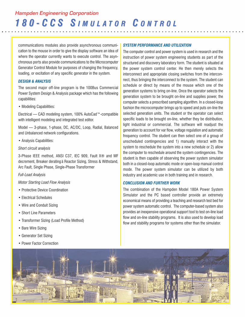
The simulator (Figure 1) is a small power system consisting ofscale generators (3), a transmission system, a subtransmissionsystem, substation and loads. The loads are both balanced and unbalanced and conformal and nonconformal loads. The generationis in the form of three DC motor/synchronous generator sets of 1kilowatt, 1 kilowatt and 3 kilowatt capacity. Additional tie capacitymay be supplied to the simulator through the system interconnec-tion. The high voltage (600 volts) transmission connects the generation of two distribution substations where residential and industrial loads are simulated. There is also a network system fedfrom both the substations, and the load center substation as well.The circuit breakers and certain control switches are specially mod-ified allowing them to be operated remotely by the computer oncommand, thus simulating the supervisory control capability of anactual power system.
THE COMPUTER
The Instructor’s computer consists of a Pentium class computerconfigured with 1Gb of random access memory, two serial ports(COM1 and COM2), a parallel ink-jet printer connected to LPT1,and an 19" (48.3 cm) VGA LCD graphics display as configured asthe primary display. The computer is also equipped with a PCmouse, which allows the operator to interact with the displays beingprovided by the computer. This interaction consists of displaying theresults of the embedded systems acquisition of specific voltageand parameters within the network and also allowing the operatorto interface with the network to perform switching functions.
SIMULATOR INTERFACE
The simulator interface circuitry is used to perform level changesbetween the 4 volt TTL signals available on the TTL discrete controller board within the PC, and the 1Ø AC commands neededto operate the controls within the simulator. The purpose of this interface, in addition to the level conversion, is to offer a high levelof isolation between the system simulator and the computer. Inorder to accomplish this, a relay triac opto-isolator arrangementhas been utilized.
MICROCOMPUTER SUBCONTROLLER SYSTEM
The microcontroller subcontroller system is provided to performclosed-loop control of the generators during normal operation ofthe power system simulator and to provide synchronizing data tothe PC when a generator is added or removed from the power system during normal operation of the power system simulator.
SYSTEM DESCRIPTION
The control software on the computer unifies and integrates thecontrol of the distributed component. The computer performs normally closed-loop tasks, that is, providing automatic voltage andspeed control and power control of the individual generating units.The computer provides a supervisory control to the generator controller in the form of AGC commands and whether or not theunits are to be committed or not, and what the individual voltagelevels are to be scheduled on each one of the units.
CONTROLLER SOFTWARE
The software is written in modular form, using Visual Basic as theprimary language. The software is structured as a display softwaremodule, a data acquisition module, a controls module and a communications module. The display handles all interaction between the individual user and the software. In addition, it handles the display of individual network subsystems and the appropriate data from the data acquisition system. The control software gathers data from the display software as to the switching decisions of the operator. It then relays this to the I/Ochips which then interact with the interface equipment to performnetwork switching in the simulator. The data acquisition modulecontrols the Data Translations A/D converter. This data acquisitionmodel gathers specific needed state variables from the power system simulator as to voltages, currents, phase information, andpower flows. This data is then gathered and passed through a common array to the display module where it can be displayed onthe various one-line diagrams that the operator brings forward. The

Hampden Engineering Corporation
RR O O MO O M LL A Y O U TA Y O U T
Hampden Engineering Corporation
SS E C T I O NE C T I O N OO N EN E
SECTION 1—GENERATOR UNIT-1/POWER PLANT
• This section contains provisions for two separately supplied 1.5-kilowatt 3-phase AC alternators.
• Voltage, current in each phase, power factor, and power instrument is provided for each alternator.
• Also supplied is a provision for the control of the field excitation of each alternator.
• Provisions are made for control of (1) 125V DC power supply from the station service to be used as a power source for relaying.
• Generator-1 has protection for differential, ground overcurrent, reverse power, ground fault, loss of excitation, under / over frequency, under / over voltage, over current, loss of synchronization, and transformer protection.
• The end of Section-1 contains amphenol connectors for Generator-2 excitation, Generator-2 drive motor and Generator-2 output forthe connectors of the mobile Generator-2.
• Provides one synchroscope with five synchroscope instrument switches, one for each of two generators, and one for each of threelines coming onto the main bus in generating station #1.
• Also provide a ring bus network complete with isolation circuit breakers. This bus serves as Station #3 and ties the generation andtransmission lines together at the high voltage level.
180A POWER SYSTEM SIMULATOR ROOM LAYOUT180A POWER SYSTEM SIMULATOR ROOM LAYOUT
Standard Products…Designed to Meet Your Growing Needs! Standard Products…Designed to Meet Your Growing Needs!
A. Hampden 180A Seven-Section Power SystemSimulator
B. Hampden Grill door and Enclosure Sections
C. Hampden H-REM-180 Motor Generatormounted on H-REM-180-MR Rack Assembly
D. Hampden Pancake Duct
E. Hampden 262-180 Power System SimulatorConsole
F. Hampden HC-2563-1 Arm Swivel Chair
G. Hampden H-CS Computer Terminal
Ring Bus
Synchroscope & Line Selector Switches
Generator-1 Over Current & Reverse Power Relay
Generator-1 Instrumentation
Generator-1 VFD Control
Generator-1 Excitation Control
Generator-1 Output Circuit Control
Start-up Transformer
Instrument Transformers
Isolation Switch

Hampden Engineering Corporation
SS E C T I O NE C T I O N TT W OW O
Hampden Engineering Corporation
SS E C T I O NE C T I O N SS E V E NE V E N
SECTION 2—SYNCHRONIZING AND GENERATOR UNIT-2
• This section also contains provisions for the second generator, station and agricultural service, line #B1-3 instrumentation, and station-l instrumentation.
• The station and agricultural service consists of a step-down transformer; disconnect means and loading scaled to depict a similar circumstance on a typical power system.
• Line #B 1-3 contains over-current relays, voltage, current and power instrumentation, so that the accumulated power output of station 1 can be monitored and recorded.
• Station #1 contains frequency monitoring for several points in the system, and transmission line directional relaying.
SECTION 7—INTERCONNECTION
• Provision is made on this section for interconnection to the local utility company and this depicts one company tying in with another. The interconnection instrumentation includes a revenue kilowatt hour meter, voltmeter, ammeter and frequency meter. Alsoprovided as part of the interconnection, is a 3-phase voltage regulator for adjusting the system voltage level. The interconnectionfeeds a double bus system which provides taps for the transmission lines to the other generating stations located at the other endof the board and also feed lines to the distribution network.
• Two directional relays are provided, so that a study of transmission line faults can be conducted on lines
• C1-11 and D1-11. Faults will be built into the panel so that proper operation of the relays can be investigated and the sequence ofevents studied.
• This section contains the main power circuit breaker with key lock for the entire switchboard. This circuit breaker controls both thepower to the interconnection circuit breaker and the power to the DC system supply so that complete control of the system simulator is maintained from this single circuit breaker. Two emergency pushbuttons, one on this section and one on Section 1 areprovided so that the system can be immediately shut down, should any problem develop, which could constitute a safety hazard.These emergency stations will operate the main simulator power supply circuit breaker so that no power will be left energized onthe board. Provision will be made for further remotely located emergency pushbutton stations which can be located anywhere in thelaboratory as required.
• Provision will be made for control of a 125V DC power supply from the station service to be used as a power source for relaying.
• Provision will be made for control of the computer power source and the 5 VDC control power source.
Standard Products…Designed to Meet Your Growing Needs! Standard Products…Designed to Meet Your Growing Needs!
Wattmeter and Line Selector Switch
Transmission Line 3Ø Over Current Relay
Station Load Control
Synchronizing
Lamps and
Line Selector
Switch
Over Current
and Line
Directional
Relay
Pilot Lights to indicate when the line is energized
Interconnect Voltage Regulator
Shut Down for Main Circuit Breaker
Typical Double Bus Station
Over Current and Line Directional Relays
Interconnection and Watthour Meter
Control Circuit Breakers
Main Power Lockable Circuit Breaker with Emergency
Trip Push Button for Complete Shut Down
Interconnect Instrumentation

Hampden Engineering Corporation
SS E C T I O NE C T I O N SS I XI X
Hampden Engineering Corporation
SS E C T I O NE C T I O N TT H R E EH R E E
SECTION 3—15KV SUBSTATION
• Section 3 provides provisions for sub-station #4, which transforms the transmission voltage down to distribution voltages and fromdistribution voltages down to residential and industrial voltages. The five circuit breakers in sub-station #4 depicts air circuit break-ers which would actually be used in the substation application.
• One of the transformers is constructed in such a manner that it has a built-in fault which can be manually controlled, and which willoverload the unit, yet not destroy it. We have also provided a differential relay for the study of transformer faults, and provision for trending current flow, and a recording temperature meter for the transformer study.
• Seven residential loads are included, each with its own fused disconnect switch operable from the front of the board with the fusingon the rear of the board.
• Each load is timer controlled with indicating light and control switch. The load is a multi-step so that a cycle of loading can be plotted, forming a discreet loading curve for a typical period of time.
• The residential loads are complete with a revenue kilowatt-hour meter to monitor groups of loads by phases, with recording capabilities.
• Also included is a 1Ø residential type ground fault detector so that an analysis can be made of its function.
SECTION 6—TRANSMISSION LINES
• This section provides the remaining portion of sub-station 6 double bus substation, including the second feeder. This sub-station depicts the two-bus system with the main bus and auxiliary bus, along with the proper bypass switches and connecting circuit breakers.
• The lower portion of this panel contains a selection of circuit breakers properly connected to depict a load center substation, with aselective secondary, consisting of proper interlocking of incoming power so that either line may feed the entire station or the stationcan be split into and fed from two sources of power.
• This sub-station has provision for monitoring the current coming in via each feeder and a bus voltmeter. The four distribution circuit breakers are available as feeders to a remotely located site, also being fed from the network system. Circuit #1 has provideda reverse phase relay so if motor studies are included at the output, the problem of phase reversal can be investigated.
Standard Products…Designed to Meet Your Growing Needs! Standard Products…Designed to Meet Your Growing Needs!
GFI Circuit
Residential Loading with Timed
Control for a Typical 24 hr Day
Compressor to a 2 hr Lab.
Circuit Breakers with
Local and Remote
OPEN/CLOSE Control
Transformer Control
for OPEN/CLOSE
Delta OperationResidential Watthour
Meter for 1Ø Loads
Transformer
Differential Meter
with Temperature
MonitoringKeyed Selective
Secondary
Substation
Selective Secondary
Circuits 1 and 2
Under Voltage and
Phase Sequencer
Protection

Hampden Engineering Corporation
SS E C T I O NE C T I O N FF O U RO U R
Hampden Engineering Corporation
SS E C T I O NE C T I O N FF I V EI V E
Standard Products…Designed to Meet Your Growing Needs!
SECTION 4—600V INDUSTRIAL SUBSTATION
• This section contains provisions for industrial loading, transformer over-current relaying, and feeder over-current relaying and powerfactor correction.
• The industrial load consists of power, heat, and lighting loads which will be monitored by voltage, current, and watthour instrumentation. A power quality and revenue type watt-hour meter is used so that its function can be investigated. The industrialloads are timer controlled similar to those provided on the residential loads so that the industrial power requirements can be includedinto the total system loading curve.
• The feeder to the industrial loads contains a manual voltage regulator, and VAR meter. The manual voltage regulator is used to depict the varying effects of over and under voltage. The power quality and revenue meter provides a record of all current requirements to the industrial load. Plus it is used to indicate the effects of the inductive load supplied as part of the industrial loadand of the capacitance added as line correction.
• The emergency source is used to depict transference of lighting from standard power to emergency power and this contains its ownvoltmeter and pilot light indicator.
• One 3Ø transformer over-current relay is provided to be used with the transformer on Section 3. Also provided is one 3Ø feeder over-current relay to be used in conjunction with the transformer over-current relay and the generator over-current relay so the systemcan be set up to depict sequential relaying as would be found in a typical power system.
SECTION 5—DOUBLE BUS SUBSTATION
• Section 5 provides a distribution system as would be found in a commercial area. It consists of a network system fed from four different points with a reverse power relay on one transformer so that network problems can be analyzed.
• Two 3-phase 4-wire distribution circuits are supplied from the network system complete with a disconnect switch and behind thepanel fusing. These circuits are available for termination at a remotely located site. The distribution circuit has a voltmeter and ammeter, each with phase selection instrumentation switches.
• A portion of sub-station 6 double bus substation is incorporated into the switchboard section and consists of one feeder circuit and part of the distribution circuits and a voltmeter to monitor the bus voltage.
Transmission Line
3Ø Over Current Relays
for Sequential Operation
Line Selection for
Power Factor
Monitoring
Line Selection for
Power Factor
Monitoring
Industrial Load
Line Regulator
Industrial Loading with
Inductive Reactive
Load Selection
Industrial
Watthour Meter
for 3Ø Loads
Capacitance
Reactive Industrial
Line Correction
Emergency Loading
Network Voltage
and Current
Instrumentation
Network System
with Phase
Sequencer, Under
Voltage and
Reverse Power
Protection

Hampden Engineering Corporation
SS E C T I O NE C T I O N SS I XI X
Hampden Engineering Corporation
SS E C T I O NE C T I O N TT H R E EH R E E
SECTION 3—15KV SUBSTATION
• Section 3 provides provisions for sub-station #4, which transforms the transmission voltage down to distribution voltages and fromdistribution voltages down to residential and industrial voltages. The five circuit breakers in sub-station #4 depicts air circuit break-ers which would actually be used in the substation application.
• One of the transformers is constructed in such a manner that it has a built-in fault which can be manually controlled, and which willoverload the unit, yet not destroy it. We have also provided a differential relay for the study of transformer faults, and provision for trending current flow, and a recording temperature meter for the transformer study.
• Seven residential loads are included, each with its own fused disconnect switch operable from the front of the board with the fusingon the rear of the board.
• Each load is timer controlled with indicating light and control switch. The load is a multi-step so that a cycle of loading can be plotted, forming a discreet loading curve for a typical period of time.
• The residential loads are complete with a revenue kilowatt-hour meter to monitor groups of loads by phases, with recording capabilities.
• Also included is a 1Ø residential type ground fault detector so that an analysis can be made of its function.
SECTION 6—TRANSMISSION LINES
• This section provides the remaining portion of sub-station 6 double bus substation, including the second feeder. This sub-station depicts the two-bus system with the main bus and auxiliary bus, along with the proper bypass switches and connecting circuit breakers.
• The lower portion of this panel contains a selection of circuit breakers properly connected to depict a load center substation, with aselective secondary, consisting of proper interlocking of incoming power so that either line may feed the entire station or the stationcan be split into and fed from two sources of power.
• This sub-station has provision for monitoring the current coming in via each feeder and a bus voltmeter. The four distribution circuit breakers are available as feeders to a remotely located site, also being fed from the network system. Circuit #1 has provideda reverse phase relay so if motor studies are included at the output, the problem of phase reversal can be investigated.
Standard Products…Designed to Meet Your Growing Needs! Standard Products…Designed to Meet Your Growing Needs!
GFI Circuit
Residential Loading with Timed
Control for a Typical 24 hr Day
Compressor to a 2 hr Lab.
Circuit Breakers with
Local and Remote
OPEN/CLOSE Control
Transformer Control
for OPEN/CLOSE
Delta OperationResidential Watthour
Meter for 1Ø Loads
Transformer
Differential Meter
with Temperature
MonitoringKeyed Selective
Secondary
Substation
Selective Secondary
Circuits 1 and 2
Under Voltage and
Phase Sequencer
Protection

Hampden Engineering Corporation
SS E C T I O NE C T I O N TT W OW O
Hampden Engineering Corporation
SS E C T I O NE C T I O N SS E V E NE V E N
SECTION 2—SYNCHRONIZING AND GENERATOR UNIT-2
• This section also contains provisions for the second generator, station and agricultural service, line #B1-3 instrumentation, and station-l instrumentation.
• The station and agricultural service consists of a step-down transformer; disconnect means and loading scaled to depict a similar circumstance on a typical power system.
• Line #B 1-3 contains over-current relays, voltage, current and power instrumentation, so that the accumulated power output of station 1 can be monitored and recorded.
• Station #1 contains frequency monitoring for several points in the system, and transmission line directional relaying.
SECTION 7—INTERCONNECTION
• Provision is made on this section for interconnection to the local utility company and this depicts one company tying in with another. The interconnection instrumentation includes a revenue kilowatt hour meter, voltmeter, ammeter and frequency meter. Alsoprovided as part of the interconnection, is a 3-phase voltage regulator for adjusting the system voltage level. The interconnectionfeeds a double bus system which provides taps for the transmission lines to the other generating stations located at the other endof the board and also feed lines to the distribution network.
• Two directional relays are provided, so that a study of transmission line faults can be conducted on lines
• C1-11 and D1-11. Faults will be built into the panel so that proper operation of the relays can be investigated and the sequence ofevents studied.
• This section contains the main power circuit breaker with key lock for the entire switchboard. This circuit breaker controls both thepower to the interconnection circuit breaker and the power to the DC system supply so that complete control of the system simulator is maintained from this single circuit breaker. Two emergency pushbuttons, one on this section and one on Section 1 areprovided so that the system can be immediately shut down, should any problem develop, which could constitute a safety hazard.These emergency stations will operate the main simulator power supply circuit breaker so that no power will be left energized onthe board. Provision will be made for further remotely located emergency pushbutton stations which can be located anywhere in thelaboratory as required.
• Provision will be made for control of a 125V DC power supply from the station service to be used as a power source for relaying.
• Provision will be made for control of the computer power source and the 5 VDC control power source.
Standard Products…Designed to Meet Your Growing Needs! Standard Products…Designed to Meet Your Growing Needs!
Wattmeter and Line Selector Switch
Transmission Line 3Ø Over Current Relay
Station Load Control
Synchronizing
Lamps and
Line Selector
Switch
Over Current
and Line
Directional
Relay
Pilot Lights to indicate when the line is energized
Interconnect Voltage Regulator
Shut Down for Main Circuit Breaker
Typical Double Bus Station
Over Current and Line Directional Relays
Interconnection and Watthour Meter
Control Circuit Breakers
Main Power Lockable Circuit Breaker with Emergency
Trip Push Button for Complete Shut Down
Interconnect Instrumentation

Hampden Engineering Corporation
RR O O MO O M LL A Y O U TA Y O U T
Hampden Engineering Corporation
SS E C T I O NE C T I O N OO N EN E
SECTION 1—GENERATOR UNIT-1/POWER PLANT
• This section contains provisions for two separately supplied 1.5-kilowatt 3-phase AC alternators.
• Voltage, current in each phase, power factor, and power instrument is provided for each alternator.
• Also supplied is a provision for the control of the field excitation of each alternator.
• Provisions are made for control of (1) 125V DC power supply from the station service to be used as a power source for relaying.
• Generator-1 has protection for differential, ground overcurrent, reverse power, ground fault, loss of excitation, under / over frequency, under / over voltage, over current, loss of synchronization, and transformer protection.
• The end of Section-1 contains amphenol connectors for Generator-2 excitation, Generator-2 drive motor and Generator-2 output forthe connectors of the mobile Generator-2.
• Provides one synchroscope with five synchroscope instrument switches, one for each of two generators, and one for each of threelines coming onto the main bus in generating station #1.
• Also provide a ring bus network complete with isolation circuit breakers. This bus serves as Station #3 and ties the generation andtransmission lines together at the high voltage level.
180A POWER SYSTEM SIMULATOR ROOM LAYOUT180A POWER SYSTEM SIMULATOR ROOM LAYOUT
Standard Products…Designed to Meet Your Growing Needs! Standard Products…Designed to Meet Your Growing Needs!
A. Hampden 180A Seven-Section Power SystemSimulator
B. Hampden Grill door and Enclosure Sections
C. Hampden H-REM-180 Motor Generatormounted on H-REM-180-MR Rack Assembly
D. Hampden Pancake Duct
E. Hampden 262-180 Power System SimulatorConsole
F. Hampden HC-2563-1 Arm Swivel Chair
G. Hampden H-CS Computer Terminal
Ring Bus
Synchroscope & Line Selector Switches
Generator-1 Over Current & Reverse Power Relay
Generator-1 Instrumentation
Generator-1 VFD Control
Generator-1 Excitation Control
Generator-1 Output Circuit Control
Start-up Transformer
Instrument Transformers
Isolation Switch
POWER INPUTS
The typical power requirements are as follows:
• 120/208V–3Ø–4W–40A, or 220/380V–3Ø–4W–25A, or 240/415V–3Ø–4W–25A
POWER SYSTEM SIMULATOR—GENERALThe intent of the Power System Simulator is to incorporate allaspects of a power system from generation and interconnec-tion through transmission to distribution. Three distinct levelsof voltage are utilized. The 208* or 220* volt level will be usedfor interconnection and generation, as well as for residential and network voltages, 380* volts will be used bythe distribution and industrial levels and 600* volts will beused for the transmission levels.
* These voltages are adapted to the voltages at the end user’s
site.
Section 1 contains facilities for generation and a substationincorporating the generation and power transmission.
Section 2 contains facilities for synchronization and generationand a station incorporating the generation and power trans-mission.
Section 3 incorporates a distribution sub-station and distribu-tion functions covering residential distribution.
Section 4 is an industrial sub-station and distribution functionscovering industrial distribution.
Sections 5 & 6 incorporate a double bus distribution sub-sta-tion, a network system and a selective secondary distributionload center.
Section 6 incorporates the line settings for two transmissionlines.
Section 7 incorporates facilities for inter-connection with aseparate power system (in the case of this power system simulator, it would be a local power company) and contains facilities for generation and a substation incorporating the gen-eration and power transmission.
TRANSMISSION LINE STUDIESIn order to expand the utilization of the Power System Simulator, additional equipment has been added to varioussections of the switchboard, enabling an expanded study oftransmission lines.
Additional equipment provides the means of studying the following topics:
A. General Transmission LinesB. Overhead Transmission LinesC. Parallel Transmission LinesD. Underground Transmission Lines
The first experiment covers a general introduction to the various aspects of electric power transmission.
The second experiment covers overhead lines. Specifically itinvolves:
A. The effect of line impedance on voltage regulationand line losses.
B. The relationship between voltage, load, power factor, and losses.
The third experiment is an expansion of the second experimentcovering the same parameters on parallel lines having unequalimpedance.
The fourth experiment covers the inherent limitations of highvoltage underground cables due to shunt capacitances. It alsosimulates typical corrective measurements in present use.
The additional equipment consists of the simulated transmis-sion line components as shown graphically on the bottom ofthe sixth switchboard section labeled sub-stations, additionalinstrumentation is also required and is shown on sections two,four, and seven, as control switches for various motors.
Hampden Engineering Corporation
PP O W E RO W E R SS Y S T E MY S T E M SS I M U L A T O RI M U L A T O R
Hampden Engineering Corporation
1 8 0 - C C S S1 8 0 - C C S S I M U L A T O RI M U L A T O R CC O N T R O LO N T R O L
SYSTEM CONFIGURATION
The power system simulator is equipped with remotely program-mable switching, relaying and generator control. Additionally, critical state variables within the power system simulator werebrought out to a central point for easy access by data acquisitionsystems.
A small microcomputer capable of handling the on-line controlproblem and graphic display, was interfaced to the power systemsimulator.
The PC performs data acquisition on the power system simulatorsvia a high speed data acquisition system. The PC then scales, errorchecks and displays the data on the VGA graphics system. On-linesystem simulation and unobserved state variables are determinedas a separate task in the PC. This on-line simulation consists of amulti-bus, multi-area PC based load flow program.
POWER SYSTEM SIMULATOR
The simulator (Figure 1) is a small power system consisting ofscale generators (3), a transmission system, a subtransmissionsystem, substation and loads. The loads are both balanced and unbalanced and conformal and nonconformal loads. The generationis in the form of three DC motor/synchronous generator sets of 1kilowatt, 1 kilowatt and 3 kilowatt capacity. Additional tie capacitymay be supplied to the simulator through the system interconnec-tion. The high voltage (600 volts) transmission connects the generation of two distribution substations where residential and industrial loads are simulated. There is also a network system fedfrom both the substations, and the load center substation as well.The circuit breakers and certain control switches are specially mod-ified allowing them to be operated remotely by the computer oncommand, thus simulating the supervisory control capability of anactual power system.
THE COMPUTER
The Instructor’s computer consists of a Pentium class computerconfigured with 1Gb of random access memory, two serial ports(COM1 and COM2), a parallel ink-jet printer connected to LPT1,and an 19" (48.3 cm) VGA LCD graphics display as configured asthe primary display. The computer is also equipped with a PCmouse, which allows the operator to interact with the displays beingprovided by the computer. This interaction consists of displaying theresults of the embedded systems acquisition of specific voltageand parameters within the network and also allowing the operatorto interface with the network to perform switching functions.
SIMULATOR INTERFACE
The simulator interface circuitry is used to perform level changesbetween the 4 volt TTL signals available on the TTL discrete controller board within the PC, and the 1Ø AC commands neededto operate the controls within the simulator. The purpose of this interface, in addition to the level conversion, is to offer a high levelof isolation between the system simulator and the computer. Inorder to accomplish this, a relay triac opto-isolator arrangementhas been utilized.
MICROCOMPUTER SUBCONTROLLER SYSTEM
The microcontroller subcontroller system is provided to performclosed-loop control of the generators during normal operation ofthe power system simulator and to provide synchronizing data tothe PC when a generator is added or removed from the power system during normal operation of the power system simulator.
SYSTEM DESCRIPTION
The control software on the computer unifies and integrates thecontrol of the distributed component. The computer performs normally closed-loop tasks, that is, providing automatic voltage andspeed control and power control of the individual generating units.The computer provides a supervisory control to the generator controller in the form of AGC commands and whether or not theunits are to be committed or not, and what the individual voltagelevels are to be scheduled on each one of the units.
CONTROLLER SOFTWARE
The software is written in modular form, using Visual Basic as theprimary language. The software is structured as a display softwaremodule, a data acquisition module, a controls module and a communications module. The display handles all interaction between the individual user and the software. In addition, it handles the display of individual network subsystems and the appropriate data from the data acquisition system. The control software gathers data from the display software as to the switching decisions of the operator. It then relays this to the I/Ochips which then interact with the interface equipment to performnetwork switching in the simulator. The data acquisition modulecontrols the Data Translations A/D converter. This data acquisitionmodel gathers specific needed state variables from the power system simulator as to voltages, currents, phase information, andpower flows. This data is then gathered and passed through a common array to the display module where it can be displayed onthe various one-line diagrams that the operator brings forward. The
SPECIFIC MATERIALS
InstrumentsAll instruments for the power simulator are of the switchboardmounting type with an accuracy of 1% and will be manufactured bythe Yokogawa Electric Company or Schweitzer Engineering Laboratories, Inc.
Circuit BreakersThe circuit breakers are of two types, the first being the de-ion airtype enclosed in bakelite housings and properly rated for voltage and current required and manufactured by the Westing-house or General Electric Corporations. The second type is hydraulic magnetic, properly rated for the voltage and current required in each specific application, and of the relay trip type whererequired, and manufactured by Airpax or Heinemann Electric Company.
TransformersAll transformers for use in the power simulator are dry type, double wound units with two 2 ½% taps above/below nominal voltage on all 3Ø units. It will be as manufactured by the NothelferWinding Laboratories, EPCO, Westinghouse, or General ElectricCompanies.
PANEL DESIGNATION
All receptacles, switches, circuit breakers, and other equipment required on the various panels are silk-screened with propernomenclature of ratings, polarity symbols and other necessary description to clearly identify the functions.
The top of each panel of the main board is silk-screened with 1-1/2 inch (3.8 cm) high letters designating the service of the panel.
Equipment contained within the confines of the panel, such astransformers, etc., are silk-screened on the face of the panel and allconnecting lines and bussing are silk-screened also and/or stripedon the panel so that the entire system is graphically represented bythe one-line diagram and symbols.
The lines are weighted in relationship to their voltage level, i.e. thehigher voltages are heavier lines and substation or busses are alsoof heavier weight to depict a main feed.
CONSTRUCTION
The entire switchboard consists of seven sections fastened together to make a total approximate length of 16 feet (4.88 m) andthey measure a total of 90" (228.6 cm) high overall and are wall-braced and spaced approximately 60 inches (152.4 cm) fromthe wall, completely mounted on a 1-1/2"x 4" (3.8 cm x 10.2 cm)channel iron base. Width for each section is as follows: Section 1- 29" (73.7 cm), Section 2 - 33.5" (85.1 cm), Section 3 - 33"(83.8 cm), Section 4 - 23" (58.4 cm), Section 5 - 23.5" (59.7cm), Section 6 - 25" (63.5 cm), Section 7 - 25" (63.5 cm)
All construction of the main board is fabricated of 1/8" (.3 cm) thick furniture stock steel formed back four inches (10.2cm) on all sides with an additional 1-1/2" (3.8 cm) return form onthe rear of the panel so that equipment can be fastened to the rear.
Hampden Engineering Corporation
1 8 0 - C C S S1 8 0 - C C S S I M U L A T O RI M U L A T O R CC O N T R O LO N T R O L
Hampden Engineering Corporation
PP O W E RO W E R SS Y S T E MY S T E M SS I M U L A T O RI M U L A T O R
communications modules also provide asynchronous communi-cation to the mouse in order to give the display software an idea ofwhere the operator currently wants to execute control. The asyn-chronous ports also provide communications to the MicrocomputerGenerator Control Module for purposes of changing the frequency,loading, or excitation of any specific generator in the system.
DESIGN & ANALYSIS
The second major off-line program is the 100Bus CommercialPower System Design & Analysis package which has the followingcapabilities:
• Modeling Capabilities:
Electrical — CAD modeling system, 100% AutoCad™-compatiblewith intelligent modeling and integrated test editor.
Model — 3-phase, 1-phase, DC, AC/DC, Loop, Radial, Balancedand Unbalanced network configurations.
• Analysis Capabilities:
Short circuit analysis
3-Phase IEEE method, ANSI C37, IEC 909, Fault X® and MF decrement, Breaker derating ä Reactor Sizing, Stress & Withstand,Arc Fault, Single Phase, Single-Phase Transformer
Full-Load Analysis
Motor Starting Load Flow Analysis
• Protective Device Coordination
• Electrical Schedules
• Wire and Conduit Sizing
• Short Line Parameters
• Transformer Sizing (Load Profile Method)
• Bare Wire Sizing
• Generator Set Sizing
• Power Factor Correction
SYSTEM PERFORMANCE AND UTILIZATION
The computer control and power system is used in research and theinstruction of power system engineering students as part of thestructured and discovery laboratory form. The student is situated atthe power system control center. He then merely selects the interconnect and appropriate closing switches from the intercon-nect, thus bringing the interconnect to the system. The student canschedule or direct by means of the mouse which one of the generation systems to bring on-line. Once the operator selects thegeneration system to be brought on-line and supplies power, thecomputer selects a prescribed sampling algorithm. In a closed-loopfashion the microcomputer brings up to speed and puts on-line theselected generation units. The student or the operator can selectspecific loads to be brought on-line, whether they be distribution,light industrial or commercial. The software will readjust the generation to account for var flow, voltage regulation and automaticfrequency control. The student can then select one of a group of unscheduled contingencies and 1) manually interact with the system to reschedule the system into a new schedule or 2) allowthe computer to reschedule around the system contingencies. Thestudent is then capable of observing the power system simulatorboth in a closed-loop automatic mode or open-loop manual controlmode. The power system simulator can be utilized by both industry and academic use in both training and in research.
CONCLUSION AND FURTHER WORK
The combination of the Hampden Model 180A Power System Simulator and the PC based controller provide an extremely economical means of providing a teaching and research test bed forpower system automatic control. The computer-based system alsoprovides an inexpensive operational support tool to test on-line loadflow and on-line stability programs. It is also used to develop loadflow and stability programs for systems other than the simulator.

GENERALThe essence of all operations are modeled on a typical central station utility. Basic system operations include:
• Time
• Diversity of Loads
• Multiple Sources of Generation
• Interconnection of Systems
Understanding of these concepts is necessary for any successful presentation or study of basic central station utility systems, and also form the basis for the design and developmentof new sources of reliable power.
The control panel of Hampden’s Power System Simulator has beendesigned to provide full functionality and control for the followingoperational factors:
1. LOADS
The panel includes simulations for constantly varying levels of consumer loads including; industrial, commercial, residential, andstreet lighting requirements.
The primary element of time is introduced, for example; daytime industrial loads, evening commercial applications, 24-hour residential utilizations, and street lighting. The standard time cyclehas been compressed so that a 2 hour real-time session will include a complete 24-hour normal load cycle.
2. VARIABLES IN THE SUPPLY OF ELECTRICITY
There are two variables—frequency and voltage. There existthoughts in the minds of customers of electric power companiesthat variations in the operations of their individual plants are somehow traceable to the characteristics of the electric supply.
As a teaching station, the control panel has features for this discussion and to demonstrate the effects of variations in frequency,voltage or both.
3. DEMAND METERING
Short-period demands exist. The control panel provides the user ofthe panel the major consideration of demands in the allocation of charges applicable to customers’ peak loads. Suchdiscussion leads into the ratings of equipment as needed to carrycertain loads over stated periods. Again, working backwards fromload to generation, this diversity governs the ratings of major placesof equipment.
4. TRANSMISSION
The entire economic justification for higher and higher levels of volt-age cannot be portrayed simply. Yet, leaving aside all the considerations of right-of-way which govern the total cost of own-ership, technically, the importance of higher voltage transmissioncan be readily made demonstrable by voltage changing equipmentin combination with some relatively simple metering of line loss andvoltage drop.
5. RELIABILITY OF SERVICE
The board serves to emphasize the fundamental objective of main-taining service with a minimum of interruption. This is somewhat incontrast to one which may emphasize relaying, as relaying usually stresses protection of equipment.
The basic conception of the purpose of protective switch-gear is toisolate faulty equipment and thereby preserve the continuity of supply. This basic concept can be shown with thecontrol panel.
The common residential service overcurrent equipment eitherserves to protect customers’ wiring or to isolate a faulty member of a utility system, depending upon one’s viewpoint.
6. LOCAL GENERATION
The control panel demonstrates the use of local generation relative to its assistance in maintaining continuity of service andfulfilling requirements of peak-load periods.
7. FEEDER DESIGN
The board has sectionalizing switches in feeders. These switchesadd flexibility. They are used to locate faults through line sectionalizing. Also, for continuity of supply, they are used as selective switches to normal or emergency sources.
Double busses at substation are included with alternate switching for purposes of discussion about circuit breaker testing and maintenance.
8. OTHER EXPERIMENTS
Other experiments concerned with aspects of the utility field can beworked.
Hampden Engineering Corporation
PP O W E RO W E R SS Y S T E MY S T E M SS I M U L A T O RI M U L A T O R
Hampden Engineering Corporation
1 8 0 - M S P1 8 0 - M S P O W E RO W E R SS Y S T E M SY S T E M S MM O D E L I N GO D E L I N G
MODEL 180-MS POWER SYSTEMS MODELING
This training method, Power Systems Modeling, starts the operator at the computer developing a power system model andverifying it on the simulator.
Through the use of the texts provided with the trainer, the studentis shown how to create a power systems model using the graphictools resident in software. Then this model, along with its predetermined responses and actions, can be applied to the simulator, and its performance studied. Various math and engineering analysis tools are provided, such as power factor analysis, curve shaping and fitting, speed control and automaticsynchronization.
The software in the complete system is comprised of three modules, consisting of: A/D—Display Module, Control Module, andSimulation Module
The first of the modules is the A/D—Display module. This moduleruns on the real time clock and gathers data from 48 channels ofanalog data, scales the data, and buffers the data in a commonglobal map for use by the display and solution modules. The Display Module contains the menu-driven man-machine interfacesoftware necessary for the selection of the simulator function.
The display software will display the transmission, distribution, andnetwork as well as the generation sections of the power systemsimulator. The display module provides a constantly displayed setof simulator data. It also has the ability to display the results thatare provided to the display module from the simulation module. Thedisplay module allows a Zoom to any part of the simulator’s circuitand accepts operator control function to be provided to the simulator via the remote control system.
The Control Module allows the computer to perform the action forany of 96 breakers, switches, and variac controls on the panels.In addition, the faults can also be remotely switched for instructor-controlled training.
The Simulation module allows the operator to simulate and predictthe behavior of the power system simulator under steady state aswell as transient conditions. The simulation module contains a loadflow module, short circuit module, an ACC package for generatorscheduling, and a transient and dynamic simulation package forsimulation of the simulator during the transient condition. Thesemodules function together with a power costing package that allows the operator to schedule the system with economics of generation and ties in mind.
All of the packages function together to perform an energy management and control and SCADA system similar to that foundin most modern utilities.
The system is also equipped with VFD drives (3) that cause thegenerators in the system to function as Hydro/Steam/Nuclear generation stations.
The hardware and software are integrated to simulate a small utility dispatch center complete with contingency modeling andavoidance simulation routines.
MODELING CAPABILITIES
Model up to 100 Buses/Nodes and 8,000 branches. This system includes award winning, 32bit, 100% AutoCAD compatible graphicengine. Import and Export: AutoCAD (DWG), Drawing Interchange(DXF), Windows Metafile (WMF) and more!
New intelligent modeling features. If you are a novice, you can letthe system automate the modeling process. And if you’re experienced, you will appreciate the control you get over all settings and parameters.
ANALYSIS CAPABILITIES
SHORT CIRCUIT ANALYSIS
3-phase IEEE method, ANSI C37, IEC 909, Fault X/R and MF decrement
Industrial Plant Designers, Consultants, Technical Managers, Engineering Maintenance, and Operating Personnel can now realize significant savings in manpower and cost, while consider-ably increasing the reliability, safety and efficiency of current and future industrial plants.
The system is a user-friendly, PC based software package specifi-cally created for the design, analysis, simulation, component sizing, and control of electrical power systems.
It has modeling capabilities to 100 nodes and up to 8,000 branches.With the electrical power system implemented, it is possible to runanalysis to answer your technical problems at the concept, detailedplanning, or operational phase of your installations.
Calculation methodology, tables, and formulas are open to the user,providing complete control over all critical analysis parameters.
LOAD FLOW ANALYSIS
The system’s Load Flow program has been designed to provide en-gineers with a very powerful tool to analyze and study a system fromthe following points: bus voltages (real and imaginary), angle of volt-age, bus KW and KVAR, bus power factor, flow of current, flow of KWand KVAR through branches, and line losses in KW and in KVAR.

99 Shaker Road P.O. Box 563, East Longmeadow, MA 01028-0563 • TEL. (413) 525-3981 • (888) HEC-CORP • FAX (413) 525-4741
Hampden Engineering Corporation
Hampden is committed to providing industry-leading technology.
For the latest from Hampden, visit our home page at http://www.hampden.com or e-mail us at [email protected]
100616
S C A D A S C A D A ( S( S U P E R V I S O R YU P E R V I S O R Y CC O N T R O LO N T R O L A N DA N D DD A T AA T A AA Q U I S I T I O NQ U I S I T I O N ))
Hampden Engineering CorporationT h e W o r l d L e a d e r i n T e a c h i n g E q u i p m e n tT h e W o r l d L e a d e r i n T e a c h i n g E q u i p m e n t
180A POWER SYSTEM 180A POWER SYSTEM SIMULATORSIMULATOR
GREEN
MECHANICAL
CO U N C I
L
SCADA FOR H-180 POWER SYSTEM SIMULATOR
The term SCADA was first used in the early 1960’s for data collec-tion in a variety of industrial processes. Today, we use a computer,PLC (Programmable Logic Controller), or RTU (Remote TerminalUnit) for gathering and analyzing real time data.
Hampden’s H-180 Power System Simulator utilizes SCADA to con-trol and display data through customizable built-in programmablecontrollers and a customizable HMI (Human-Machine Interface).
Figure #1: Hampden Engineering Corporations Power System Simulator
The SCADA system monitors power and controls power relays andequipment. It collects process data and displays real time data asit occurs. The data is analyzed to determine where relays havetripped on power lines, then central control is alerted that a faulthas occurred, and control procedures are implemented, such as, reclosing a faulted breaker to determine if the fault is critical. Thedata is then stored and recorded in history files stored in individualRTU’s.
Hampden’s H-180 Power System Simulator is fully functional whenpower is turned on. The simulator has its own controllers/proces-sors monitoring and recording data. When the supervisor connectsthrough the network all data can be monitored and controlled viathe simulators HMI.
Each section of the simulator screen has a detail button which canbe accessed to reveal a detailed description of the section.
Figure #2: H-180 Power Simulator Section 1 bottom detail screen
The many connected devices feed real time data to the trainer’scontroller which immediately acts on the data. Information is updated, adjusted and displayed as it happens. Accurate power information is obtained and displayed such as power consumptiondata displayed in Figure #3.
Figure #3: H-180 Power Meter 1 Detail Screen
Data is collected and stored in several devices for later historicalretrieval. But real-time events and current readings are displayed ina general table format for all devices(Figure#4)
Figure#4: H-180 Generator 1 readings table for SEL-751-1.
State of the Art State of the Art
in the Industryin the Industry


![PST 2200 Power System Simulator Laboratory - Terco [Swedish] · The Terco Power System Simulator is a hardware simulator for hands-on training and has been designed for practical](https://static.fdocuments.in/doc/165x107/5f69313af254db32ff2d5af8/pst-2200-power-system-simulator-laboratory-terco-swedish-the-terco-power-system.jpg)


