18 OBDG04 TCM 6 Speed T87A Summary Tables...output speed >= 100 RPM AND gear slip > 100 RPM Not Test...
566
Component/System Fault Code Monitor Strategy Description Malfunction Criteria Threshold Value Secondary Parameters Enable Conditions Time Required MIL Illum All 5 Cases B P0711 P0716 P0717 P0721 P0722 P0742 P077C P077D P07BF P07C0 P0716 P0717 P0721 P0722 P077C P077D P07BF P07C0 P0711 No Fault Active DTC P0711 Components powered AND Battery Voltage >= 9 V Engine Speed between for 5 seconds ECT is not defaulted 300 seconds Start-up temperature change <= 2 deg. C for a time >= 100 seconds AND TCC Slip >= 120 RPM for a time Vehicle speed >= 8 KPH for a time >= 300 seconds. engine coolant temperature >= 70 deg. C AND >= 15 deg. C 300 seconds Start-up temperature change <= 3 deg. C for a time >= 100 seconds AND TCC Slip >= 120 RPM for a time >= 300 seconds engine coolant temperature >= 70 deg. C Transmission Fluid Temperature -40 deg. C and 21 deg. C >= 300 seconds engine coolant temperature change from start-up Case 2 (Stuck sensor after warm start- up) Start-up transmission fluid temperature between 115 deg. C and 150 deg. C. Not Test Failed This Key On No Fault Pending DTCs for this drive cycle No Pass DTCs for this drive cycle 200 RPM and 7500 RPM Start-up transmission fluid temperature is available Transmission fluid temperature between -39 deg. C and 149 deg. C Case 1 (Stuck sensor after cold start-up) P0711 This test detects performance of the transmission fluid temperature sensor by comparing changes in temperature from start up and between samples to calibration values. Start-up transmission fluid temperature between 18 OBDG04 TCM 6 Speed T87A Summary Tables TCM 6 Speed T87A Section Page 1 of 52 Page 1 of 566
Transcript of 18 OBDG04 TCM 6 Speed T87A Summary Tables...output speed >= 100 RPM AND gear slip > 100 RPM Not Test...

Component/System Fault Code
Monitor Strategy Description
Malfunction Criteria Threshold Value Secondary Parameters Enable Conditions Time Required MIL Illum
All 5 Cases BP0711P0716P0717P0721P0722P0742P077CP077DP07BFP07C0
P0716P0717P0721P0722P077CP077DP07BFP07C0
P0711
No Fault Active DTC P0711
Components powered AND
Battery Voltage >= 9 V
Engine Speed between
for 5 seconds
ECT is not defaulted300 seconds
Start-up temperature change <= 2 deg. C for a time >= 100 seconds
AND TCC Slip >= 120 RPM for a time
Vehicle speed >= 8 KPHfor a time >= 300 seconds. engine coolant temperature >= 70 deg. C
AND
>= 15 deg. C300 seconds
Start-up temperature change <= 3 deg. Cfor a time >= 100 seconds
AND TCC Slip >= 120 RPM for a time >= 300 seconds
engine coolant temperature >= 70 deg. C
Transmission Fluid Temperature
-40 deg. C and 21 deg. C
>= 300 seconds
engine coolant temperature change from start-up
Case 2 (Stuck sensor after warm start-up)
Start-up transmission fluid temperature between
115 deg. C and 150 deg. C.
Not Test Failed This Key On
No Fault Pending DTCs for this drive cycle
No Pass DTCs for this drive cycle
200 RPM and 7500 RPM
Start-up transmission fluid temperature is available
Transmission fluid temperature between
-39 deg. C and 149 deg. C
Case 1 (Stuck sensor after cold start-up)
P0711 This test detects performance of the transmission fluid temperature sensor by comparing changes in temperature from start up and between samples to calibration values.
Start-up transmission fluid temperature between
18 OBDG04 TCM 6 Speed T87A Summary Tables
TCM 6 Speed T87A Section Page 1 of 52 Page 1 of 566

Component/System Fault Code
Monitor Strategy Description
Malfunction Criteria Threshold Value Secondary Parameters Enable Conditions Time Required MIL Illum
ANDVehicle speed >= 8 KPH
for a time >= 300 seconds. >= 55 deg. CCase 3 (Noisy sensor) 7 seconds
Change from previous temperature >= 20 deg. C for >= 14 events
in a time < 7 seconds.
net engine torque >= 150 Nm Time Enabled Criteria met AND and <= 1492 Nm
AND vehicle speed >= 22 KPHTransmission Fluid Temperature < 20 deg. C. and <= 511 KPH
%throttle >= 10.0%and <= 100%
engine speed >= 500 RPMto and <= 6500 RPM
engine coolant temperature >= -39 deg. Cand <= 149 deg. C
2 seconds
Engine Speed > 500 RPMAND
Engine Coolant Temperature > -39 deg. C AND < 50 deg. C
for >= 2 secondsAND
((ABS(IAT-ECT) <= 6 deg. CAND
(TFT-ECT)) > 40 deg. C OR
(ABS(IAT-ECT) > 6 deg. C AND
(TFT-ECT))) > 60 deg. C.
P0711 2.5 secondstransmission fluid temperature >= 140 deg. C P0712
for a time > 2.5 seconds. P0713 Components powered
ANDBattery Voltage >= 9 V
Engine Speed between
for 5 seconds
P0711 2.5 seconds
transmission fluid temperature <= - 40 deg. C P0712
for a time > 2.5 seconds P0713 Components powered
ANDBattery Voltage >= 9 V
Engine Speed between
for 5 seconds
2200 seconds
Transmission Fluid Temperature Sensor Circuit Low Input
P0712 Out of range low. Not Test Failed This Key On
engine coolant temperature change from start-up
Case 4 (Doesn’t warm up to at least 20 deg. C)
250 seconds when start-up temperature is >= 20 deg. C 2200 seconds when start-up temperature is <= -40 deg. C.
Case 5 (Reasonableness at start-up):Intake Air Temperature is not
defaulted
Time Enabled Criteria is determined by a lookup table ranging from
B
200 RPM and 7500 RPM
Transmission Fluid Temperature Sensor Circuit High Input
P0713 Out of range high. Not Test Failed This Key On B
200 RPM and 7500 RPM
18 OBDG04 TCM 6 Speed T87A Summary Tables
TCM 6 Speed T87A Section Page 2 of 52 Page 2 of 566

Component/System Fault Code
Monitor Strategy Description
Malfunction Criteria Threshold Value Secondary Parameters Enable Conditions Time Required MIL Illum
IF Engine run time
THEN Engine Coolant Temperature
AND not defaulted for a time
Speed SensorsAll cases P0716
P0717
P07BFP07C0
Not Low Voltage Disable
0.15 seconds
>= 800 RPM for >= 0.15 seconds
ANDNOT Low Voltage Response
Case 2: (Noisy Input Speed) 2 secondsFor sample size 80
IF the change in Input Speed <= -800 RPM
IF the change in Input Speed >= 800 RPM
>= 5OR
Low Counter >= 5OR
High Counter >= 5
P0717 1 second< 61 RPM P0729
P0731This test fails if input speed < 61 RPM P0732
AND P0733output speed > 500 RPM P0734
for a time > 1 second. P0735AND P0736
NOT Low Voltage Response P0721P0722P0716P07BF
THEN the Low Counter is incremented
Change of Input Speed between samples
<= 600 seconds
must be > 20 deg. C
>= 20 seconds.
Input/Turbine Speed Sensor Circuit Range/Performance
P0716 This test detects large changes in Input Speed and noisy Input Speed by comparing to calibration values.
Not Test Failed This Key On A
No Fault Pending DTCs for this drive cycle.
Case 1: (Unrealistically large changes in input speed)
AInput/Turbine Speed Sensor Circuit No Signal
P0717 This test detects unrealistically low value of input/turbine speed or unrealistically large changes in input/turbine speed.
Failure pending if transmission input speed
THEN the High Counter is incremented
This test fails if both the Low Counter and the High Counter
Not Test Failed This Key On
18 OBDG04 TCM 6 Speed T87A Summary Tables
TCM 6 Speed T87A Section Page 3 of 52 Page 3 of 566

Component/System Fault Code
Monitor Strategy Description
Malfunction Criteria Threshold Value Secondary Parameters Enable Conditions Time Required MIL Illum
P07C0P077CP077D
No Fault Pending DTCs P0721P0722P07BFP07C0P077CP077D
NOT Low Voltage Disable
Engine is running
Shifting completeRange attained is not neutral
Transmission fluid temperature > -25 deg. CEngine speed >= 400 RPM
Transmission output speed >= 150 RPM
All Cases Case 1:P0721 0.15 seconds
Change in output speed >= 500 RPM P0722for a time >= 0.15 seconds
ANDNOT Low Voltage Response
Case 2: (Noisy output speed) Case 2:For sample size 80 No Fault Pending DTCs for this drive
cycleP077C P077D 2 seconds
IF the change in output speed <= -500 RPMTHEN the Low Counter is incremented. NOT Low Voltage Disable
IF the change in output speed >= 500 RPM range attained NOT neutral THEN the High Counter is incremented.
Test fails if both the Low Counter and >= 5
OR the Low Counter >= 5
OR the High Counter >= 5
All Cases All Cases Not Test Failed This Key On P0721
P0722P077CP077D
No Fault Pending DTCs for this drive P077CP077D
Output Speed Sensor Circuit Range/Performance
P0721 This test detects a noisy output speed sensor or circuit by detecting large changes in output speed.
Case 1: (Unrealistically large change in output speed)
ANot Test Failed This Key On
Reverse-to-Neutral shift not in process
Output Speed Sensor Circuit No Signal
P0722 This test detects unrealistically low value of output speed or unrealistically large change in output speed.
A
18 OBDG04 TCM 6 Speed T87A Summary Tables
TCM 6 Speed T87A Section Page 4 of 52 Page 4 of 566

Component/System Fault Code
Monitor Strategy Description
Malfunction Criteria Threshold Value Secondary Parameters Enable Conditions Time Required MIL Illum
NOT Low Voltage Disable
1 second>= 600 RPM
Failure pending if for a time >= 1 seconds change in output speed >= 600 RPM
<= 600 RPM for a time > 1 seconds
4 seconds
Failure pending if output speed < 61 RPM P0729P0731P0732
< 61 RPM P0733AND P0734
range is 3rd, 4th, 5th, or 6th P0735for a time > 1 second P0736
AND P0716NOT Low Voltage Response P0717
P07BFP07C0
No Fault Pending DTCs for this drive P0716P0717P07BFP07C0
AND < 61 RPM ((net engine torque < -100 Nm Engine is running
OR Shift not in process net engine torque) > 100 Nm Range attained is not Neutral
OR (turbine speed > 1500 RPM
AND Transmission fluid temperature > -25 deg. C range is 2nd)) Transmission input speed >= 1050 RPM
for a time >= 4 seconds.AND
NOT Low Voltage Response
IF voltage <= 0.25 volts Not Test Failed This Key On P07BF 0.8 secOR
for 0.2 second No Fault Active DTC P07BF
THEN increment fail timer No Fault Active DTC P07C0IF fail timer >= 4 counts
AND NOT Low Voltage DisableEngine Speed >= 20 rpm
ANDNOT Low Voltage Response
THEN report malfunction
IF voltage >= 4.75 Not Test Failed This Key On P07C0 0.8 secOR
No Fault Active DTC P07C0for 0.2 second
THEN increment fail timer No Fault Active DTC P07BFIF fail timer >= 4 counts
AND Components poweredEngine Speed >= 20 rpm AND
Case 1: (Unrealistically large change in output speed)
Test enabled when output speed
Failure sets if range attained is Neutral Test disabled when output speed
Input/Turbine Speed Sensor Ckt Voltage High
P07C0 This test detects either open or short to ground circuit malfunctions.
Not waiting for Manual Selector Valve to attain forward range
PRNDL State is NOT D4, NOT Transitional D4
Input/Turbine Speed Sensor Ckt Voltage Low
P07BF This test detects either open or short to ground circuit malfunctions.
A
Case 2: (Unrealistically low value of output speed)
Not Test Failed This Key OnFailure sets if not monitoring for low
speed neutral and output speed
Failure sets if not monitoring for low speed neutral and output speed
Reverse to Neutral shift not in process
A
18 OBDG04 TCM 6 Speed T87A Summary Tables
TCM 6 Speed T87A Section Page 5 of 52 Page 5 of 566
Component/System Fault Code
Monitor Strategy Description
Malfunction Criteria Threshold Value Secondary Parameters Enable Conditions Time Required MIL Illum
THEN report malfunction Battery Voltage >= 9 V
IF voltage <= 0.25 volts Not Test Failed This Key On P077C 0.8 secOR
No Fault Active DTC P077Cfor 0.2 second
THEN increment fail timerIF fail timer >= 4 counts No Fault Active DTC P077D
ANDEngine Speed >= 20 rpm NOT Low Voltage Disable
ANDNOT Low Voltage Response
THEN report malfunction
IF voltage >= 4.75 Not Test Failed This Key On P077D 0.8 secOR
No Fault Active DTC P077Dfor 0.2 second
THEN increment fail timer No Fault Active DTC P077CIF fail timer >= 4 counts
AND Components poweredEngine Speed >= 20 rpm AND
THEN report malfunction Battery Voltage >= 9 V
Range Verification
>= 2 second2.25 seconds
P0877
IF main pressure dropout is suspected P0878
THEN accumulated event timer is >= 1 secondIF main pressure dropout is detected P0877
THEN accumulated event timer is >= 0.75 second
P0877AND
output speed >= 100 RPMAND
gear slip > 100 RPM Not Test Failed This Key On P0721
P0722
P0716P0717P07BFP07C0P077C
>= 250 RPM P077D for > 10 samples.
P0717P07BFP07C0
NOT Low Voltage Disable
No range switch response active
Hydraulic System Pressurized
P0731
In response to pending failure, a diagnostic response range is
commanded.
During this command, this test fails if Abs(Converter Slip)
Gear 1 Incorrect Ratio
Not Fault Pending with cmd gear Rev_Logic1 and RPS/PRNDL conflict
Output Speed Sensor Ckt Voltage Low
P077C This test detects either open or short to ground circuit malfunctions.
A
Output Speed Sensor Ckt Voltage High
P077D This test detects either open or short to ground circuit malfunctions.
A
Pending failure occurs when accumulated event timer
Not Fault Active with cmd gear Rev_Logic1 and RPS/PRNDL conflict
No Fault Pending DTC for this drive cycle.
Not Test Failed This Key On (except if dropout suspected or detected)
Timer accumulates when transmission is in forward or reverse range
AThis test verifies transmission operating ratio while 1st range is commanded by comparing computed ratio to the commanded ratio.
18 OBDG04 TCM 6 Speed T87A Summary Tables
TCM 6 Speed T87A Section Page 6 of 52 Page 6 of 566

Component/System Fault Code
Monitor Strategy Description
Malfunction Criteria Threshold Value Secondary Parameters Enable Conditions Time Required MIL Illum
Shift complete
Output speed >= 200 RPM
>= 2 second 2.25 secondsP0877
IF main pressure dropout is suspected P0878
THEN accumulated event timer is >= 1 second
IF main pressure dropout is detected P0877THEN accumulated event timer is
>= 0.75 second
P0877
AND output speed >= 100 RPM
AND Not Test Failed This Key On P0721gear slip > 100 RPM P0722
P0716P0717P07BFP07C0P077CP077D
>= 250 RPM for > 10 samples. P0717
P07BFP07C0
NOT Low Voltage Disable
No range switch response active
Hydraulic System Pressurized
Shift complete
Output speed >= 200 RPM
Normal powertrain shutdown not in process
Normal powertrain initialization is complete
Pending failure occurs when accumulated event timer
Timer accumulates when transmission is in forward or reverse range
Not Fault Active with cmd gear Rev_Logic1 and RPS/PRNDL conflict
P0732 This test verifies transmission operating ratio while 2nd range is commanded by comparing computed ratio to the commanded ratio.
No hydraulic default condition present
Gear 2 Incorrect Ratio
During this command, this test fails if Abs(Converter Slip)
Normal powertrain shutdown not in process
No hydraulic default condition present
Not Test Failed This Key On (except if dropout suspected or detected)
Not Fault Pending with cmd gear Rev_Logic1 and RPS/PRNDL conflict
A
No Fault Pending DTC for this drive cycle.
In response to pending failure, a diagnostic response range is
commanded.
18 OBDG04 TCM 6 Speed T87A Summary Tables
TCM 6 Speed T87A Section Page 7 of 52 Page 7 of 566

Component/System Fault Code
Monitor Strategy Description
Malfunction Criteria Threshold Value Secondary Parameters Enable Conditions Time Required MIL Illum
2.25 seconds>= 2 second P0877
IF main pressure dropout is suspected P0878
THEN accumulated event timer is >= 1 secondIF main pressure dropout is detected P0877
THEN accumulated event timer is >= 0.75 second
P0877
AND output speed >= 100 RPM
AND
gear slip > 100 RPM Not Test Failed This Key On P0721P0722P0716P0717P07BFP07C0P077C
>= 250 RPM P077D for > 10 samples.
P0717P07BFP07C0
NOT Low Voltage Disable
Hydraulic System Pressurized
Shift complete
Output speed >= 200 RPM
2.25 seconds>= 2 second P0877
IF main pressure dropout is suspected P0878THEN accumulated event timer is >= 1 second
IF main pressure dropout is detected THEN accumulated event timer is >= 0.75 second P0877
AND P0877
Not Fault Pending with cmd gear Rev_Logic1 and RPS/PRNDL conflict
P0734 This test verifies transmission operating ratio while 4th range is commanded by comparing computed ratio to the commanded ratio.
Gear 4 Incorrect Ratio Pending failure occurs when accumulated event timer
Timer accumulates when transmission is in forward or reverse range
Not Fault Active with cmd gear
Gear 3 Incorrect Ratio P0733 This test verifies transmission operating ratio while 3rd range is commanded by comparing computed ratio to the commanded ratio.
Not Fault Pending with cmd gear Rev_Logic1 and RPS/PRNDL conflict
Normal powertrain initialization is complete
A
No Fault Pending DTC for this drive cycle.
In response to pending failure, a diagnostic response range is
commanded.
No range switch response active
During this command, this test fails if Abs(Converter Slip)
No hydraulic default condition present
Normal powertrain shutdown not in process
Normal powertrain initialization is complete
Pending failure occurs when accumulated event timer
Not Fault Active with cmd gear Rev_Logic1 and RPS/PRNDL conflict
Not Test Failed This Key On (except if dropout suspect or detected)
Timer accumulates when transmission is in forward or reverse range
ANot Test Failed This Key On (except if
dropout suspect or detected.)
18 OBDG04 TCM 6 Speed T87A Summary Tables
TCM 6 Speed T87A Section Page 8 of 52 Page 8 of 566

Component/System Fault Code
Monitor Strategy Description
Malfunction Criteria Threshold Value Secondary Parameters Enable Conditions Time Required MIL Illum
output speed >= 100 RPMAND
gear slip > 100 RPM Not Test Failed This Key On P0721
P0722P0716P0717P07BFP07C0
>= 250 RPM P077C for > 10 samples. P077D
P0717P07BFP07C0
NOT Low Voltage Disable
No range switch response active
Hydraulic System Pressurized
Shift complete
Output speed >= 200 RPM
2.25 seconds>= 2 second P0877
IF main pressure dropout is suspected P0878THEN accumulated event timer is >= 1 second
IF main pressure dropout is detected THEN accumulated event timer is >= 0.75 second P0877
AND P0877 output speed >= 100 RPM
gear slip > 100 RPM
Not Test Failed This Key On P0721P0722P0716P0717P07BF
>= 250 RPM P07C0 for > 10 samples. P077C
P077D
P0717P07BF
Not Fault Active with cmd gear Rev_Logic1 and RPS/PRNDL conflict
No Fault Pending DTC for this drive cycle.
Pending failure occurs when accumulated event timer
Timer accumulates when transmission is in forward or reverse range
Normal powertrain initialization is complete
In response to pending failure, a diagnostic response range is
commanded.
Normal powertrain shutdown not in process
Rev_Logic1 and RPS/PRNDL conflict
P0735 This test verifies transmission operating ratio while 5th range is commanded by comparing computed ratio to the commanded ratio.
Not Fault Pending with cmd gear Rev_Logic1 and RPS/PRNDL conflict
Gear 5 Incorrect Ratio
In response to pending failure, a diagnostic response range is
commanded.
During this command, this test fails if Abs(Converter Slip)
No Fault Pending DTC for this drive cycle.
During this command, this test fails if Abs(Converter Slip)
No hydraulic default condition present
Not Test Failed This Key On (except if dropout suspect or detected.)
A
18 OBDG04 TCM 6 Speed T87A Summary Tables
TCM 6 Speed T87A Section Page 9 of 52 Page 9 of 566

Component/System Fault Code
Monitor Strategy Description
Malfunction Criteria Threshold Value Secondary Parameters Enable Conditions Time Required MIL Illum
P07C0
NOT Low Voltage Disable
No range switch response active
Hydraulic System Pressurized
Shift complete
Output speed >= 200 RPM
2 secondsAccumulated event timer >= 2 seconds P0877
IF main pressure dropout is suspected P0878THEN accumulated event timer is >= 1 second
IF main pressure dropout is detected THEN accumulated event timer is >= 0.75 second P0877
P0877AND
output speed >= 100 RPMAND
gear slip > 100 RPM P0721
P0722P0716P0717P07BFP07C0P077CP077D
P0717P07BFP07C0
NOT Low Voltage Disable
Hydraulic System Pressurized
Shift complete
Output speed >= 200 RPM
Reverse Incorrect Ratio P0736
Normal powertrain initialization is complete
This test verifies transmission range while reverse range is commanded by comparing computed ratio to the commanded ratio.
Timer accumulates when transmission is in forward or reverse range
A
Not Test Failed This Key On
No Fault Pending DTC for this drive cycle.
No range switch response active
No hydraulic default condition
Normal powertrain shutdown not in process
Not Fault Pending with cmd gear Rev_Logic1 and RPS/PRNDL conflict
Not Fault Active with cmd gear Rev_Logic1 and RPS/PRNDL conflict
Not Test Failed This Key On (except if dropout suspect or detected.)
No hydraulic default condition present
18 OBDG04 TCM 6 Speed T87A Summary Tables
TCM 6 Speed T87A Section Page 10 of 52 Page 10 of 566

Component/System Fault Code
Monitor Strategy Description
Malfunction Criteria Threshold Value Secondary Parameters Enable Conditions Time Required MIL Illum
2.25 seconds>= 2 second P0877
IF main pressure dropout is suspected P0878THEN accumulated event timer is >= 1 second
IF main pressure dropout is detected THEN accumulated event timer is >= 0.75 second P0877
AND P0877
output speed >= 100 RPM
ANDgear slip > 100 RPM P0721
P0722P0716P0717P07BFP07C0P077C
>= 250 RPM P077D for > 10 samples.
P0717P07BFP07C0
NOT Low Voltage Disable
No range switch response active
Hydraulic System Pressurized
Shift complete
Output speed >= 200 RPM
Torque Converter 15 seconds
TCC Slip >= 80 RPM P2761for a time >= 15 seconds. P2763
P2764P0721P0722
BNot Test Failed This Key On
A
Torque Converter Clutch Circuit Performance or Stuck Off
P0741 This test detects the torque converter being stuck off (unlocked).
No Fault Pending DTC for this drive cycle.
No hydraulic default condition present
Normal powertrain shutdown not in process
Not Fault Pending with cmd gear Rev_Logic1 and RPS/PRNDL conflict
Not Test Failed This Key On (except if dropout suspect or detect)
Pending failure occurs when accumulated event timer
Timer accumulates when transmission is in forward or reverse range
During this command, this test fails if Abs(Converter Slip)
In response to pending failure, a diagnostic response range is
commanded.
Gear 6 Incorrect Ratio P0729 This test verifies transmission range while 6th range is commanded by comparing computed ratio to the commanded ratio.
present
Normal powertrain shutdown not in process
Normal powertrain initialization is complete
Not Fault Active with cmd gear Rev_Logic1 and RPS/PRNDL conflict
Not Test Failed This Key On
Normal powertrain initialization is complete
18 OBDG04 TCM 6 Speed T87A Summary Tables
TCM 6 Speed T87A Section Page 11 of 52 Page 11 of 566

Component/System Fault Code
Monitor Strategy Description
Malfunction Criteria Threshold Value Secondary Parameters Enable Conditions Time Required MIL Illum
P0716P0717P077CP077DP07BFP07C0
P2761P2763P2764P0721P0722P0716P0717P077CP077DP07BFP07C0
Components poweredAND
Battery Voltage >= 9 V
Engine Speed between
for 5 seconds
Must be in forward range
% Throttle
Transmission fluid temperature
Time Since Range Change >= 6 secondsAND
TCC apply is completeAND
TCC pressure >= 1000 kPa
Case 1: (High Torque condition) P2761 Case 1:Set fault pending when throttle >= 70% P2763 2 Seconds
AND P2764net engine torque >= 275 Nm. P0721
P0722P0716P0717
for a time >= 2 seconds. U0100P077CP077DP07BFP07C0
P2761 Case 2:P2763 5 SecondsP2764
>= 100 RPM/second P0721P0722
No Fault Pending DTCs for this drive cycle.
200 RPM and 7500 RPM
> 10 % and <= 90 %
> 5 deg. C and < 130 deg. C
Torque Converter Clutch Circuit Stuck On
P0742 This test detects the torque converter being stuck on (locked).
ANot Test Failed This Key On
Report malfunction when fault pending exists continuously
Case 2: (High Acceleration condition) No Fault Pending DTCs for this drive cycle.
Set fault pending when output shaft acceleration
18 OBDG04 TCM 6 Speed T87A Summary Tables
TCM 6 Speed T87A Section Page 12 of 52 Page 12 of 566

Component/System Fault Code
Monitor Strategy Description
Malfunction Criteria Threshold Value Secondary Parameters Enable Conditions Time Required MIL Illum
P0716P0717
for a time >= 5 seconds. U0100P077CP077DP07BFP07C0
Components poweredAND Case 3:
Battery Voltage >= 9 V 4 Seconds
Engine Speed between
for 5 secondsEngine speed not defaulted
Must be in forward range >= 40 RPM/second
for a time >= 4 seconds TCC is commanded off
TCC Slip
<=-40 RPM/second for a time >= 2.5 seconds. % Throttle >= 25%
Net Engine Torque >= 175 NmEngine speed <= 3500 RPM
Input speed <= 3500 RPMOutput speed >= 100 RPM
Pressure SwitchesTransmission Control P0701 Case 1: Startup 15 seconds A
Normal Initialization in processtransmission fluid temperature > 25 deg C
Engine Speed > 500 rpm for 6 secondsOR
Engine Speed > 400 rpm for 15 seconds
PRNDL is not Park or Neutral > 4 seconds
Case 2: Low Speed 5 sec max
Loss of Prime Enable = TRUE (Boolean)Hydraulic System Pressurized = TRUE (Boolean)
Engine Speed < 1600 rpmTurbine Speed < 1600 rpm
> 0.099609 sec Output Speed < 750 rpmCommanded Gear Neutral, Reverse, First or
Park_Neu_Monitor_DO_Always = TRUE (Boolean)OR Drive_Monitor_DO_Always = TRUE (Boolean)
> 4.0 sec Rev_Monotor_DO_Always = TRUE (Boolean)
OR> 0.099609 sec
NOT (Abnormal Powerdown prior to Initialization AND Commanded
Gear NOT low speed neutral)
This test detects low main pressure at start up and low speed and detects
Case 3: (Accel/Decel/Accel condition)
Report malfunction when output acceleration event is followed by output
deceleration event and followed by another output acceleration event. An output acceleration event occurs when
output shaft acceleration
Pressure switch dropout is suspected if any below are true:
S1 logic valve integrity test pending AND S1 valve is NOT stroked for a
time (S1_Vlv_DO = True)
S1 logic valve timeout test pending AND S1 valve is NOT stroked for a
time (S1_Vlv_TO_DO = True)
S2 logic valve integrity test pending
All pressure switches do not indicate pressure
200 RPM and 7500 RPM
>=-20 RPM and <= 20 RPM An output deceleration event occurs
when output shaft acceleration is
Report malfunction when fault pending exists continuously
In Drive/ Rev w Vlv DO. If detect in Neu/Park (immediate
18 OBDG04 TCM 6 Speed T87A Summary Tables
TCM 6 Speed T87A Section Page 13 of 52 Page 13 of 566

Component/System Fault Code
Monitor Strategy Description
Malfunction Criteria Threshold Value Secondary Parameters Enable Conditions Time Required MIL Illum
OR> 4.0 sec
OR> 0.099609 sec
OR> 4.0 sec
OR> 0.099609 sec
Report fail (If sny below True):
Commanded Gear N5N or N0N:= TRUE (Boolean)
OR= TRUE (Boolean)
OR= TRUE (Boolean)
OR= TRUE (Boolean)
OR= TRUE (Boolean)
OR= TRUE (Boolean)
OR
= TRUE (Boolean)
OR= TRUE (Boolean)
OR= TRUE (Boolean)
ORCommanded Gear 1_N:
= TRUE (Boolean)
OR= TRUE (Boolean)
OR= TRUE (Boolean)
Turbine Speed > 400 rpmOutput Speed < 600 rpm
OR
S1_Vlv_Dropout_from_1_N and (S2_Vlv_DO or S3_Vlv_DO or
S1_Vlv_DO and ( S2_Vlv_DO or S3 Vlv DO or RPS DO)
S2_Vlv_DO and (S1_Vlv_DO or S3 Vlv DO or RPS DO)
S3_Vlv_DO and (S1_Vlv_DO or S2 Vlv DO or RPS DO)
RPS_DO and (S1_Vlv_DO or S2 Vlv DO or RPS DO )
S1_Vlv_DO and (S2_Vlv_DO or S3_Vlv_DO or RPS_DO)
S2_Vlv_DO and (S1_Vlv_DO or S3_Vlv_DO or RPS_DO)
S3_Vlv_DO and (S1_Vlv_DO or S2_Vlv_DO or RPS_DO)
S1_Vlv_TO_DO and S2_Vlv_TO_DO or S3 Vlv TO DO or RPS DO
S2_Vlv_TO_DO and (S1_Vlv_TO_DO or S3 Vlv TO DO or RPS DO)
S3_Vlv_TO_DO and (S1_Vlv_TO_DO or S2 Vlv TO DO or RPS DO)
RPS_DO and (S1_Vlv_TO_DO or S2_Vlv_TO_DO or S3_Vlv_TO_DO)
AND S2 valve is NOT stroked for a time (S2_Vlv_DO = True)
S2 logic valve timeout test pending AND S1 valve is NOT stroked for a
time (S2_Vlv_TO_DO = True)
S3 logic valve integrity test pending AND S3 valve is NOT stroked for a
time (S3_Vlv_DO = True)
S3 logic valve timeout test pending AND S3 valve is NOT stroked for a
time (S3_Vlv_TO_DO = True)
RPS state is NOT REVERSE and PRNDL indicates a valid REVERSE
for a time (RPS_DO = True)
18 OBDG04 TCM 6 Speed T87A Summary Tables
TCM 6 Speed T87A Section Page 14 of 52 Page 14 of 566

Component/System Fault Code
Monitor Strategy Description
Malfunction Criteria Threshold Value Secondary Parameters Enable Conditions Time Required MIL Illum
Commanded Gear 1_1:(S2_Vlv_DO or S2_Vlv_TO_DO) = TRUE (Boolean)
RPS_DO = TRUE (Boolean)Turbine Speed > 400 rpmOutput Speed < 600 rpm
ORCommanded Gear 1_H:
= TRUE (Boolean)
OR= TRUE (Boolean)
OR= TRUE (Boolean)
Turbine Speed > 400 rpmOutput Speed < 600 rpm
ORCommanded Gear R_N:
= TRUE (Boolean)
OR= TRUE (Boolean)
OR= TRUE (Boolean)
Turbine Speed > 400 rpmOutput Speed < 600 rpm
ORCommanded Gear R_Trim:
S2_Vlv_DO and S3_Vlv_DO = TRUE (Boolean)Turbine Speed > 400 rpmOutput Speed < 600 rpm
ORCommanded Gear NLT:
Attained Gear is NLT for time > 1 secRPS_DO = TRUE (Boolean)
Turbine Speed > 400 rpmOutput Speed < 600 rpm
ORCommanded Gear N03:
S1_Vlv_DO and RPS_DO = TRUE (Boolean)ORCommanded Gear R_H:
S1_Vlv_DO and S2_Vlv_DO = TRUE (Boolean)Turbine Speed > 400 rpmOutput Speed < 600 rpm
ORCommanded Gear R_1:
S2_Vlv_DO = TRUE (Boolean)Turbine Speed > 400 rpmOutput Speed < 600 rpm
ORCommanded Gear N51:
S2_Vlv_DO and RPS_DO = TRUE (Boolean)ORCommanded Gear 2_1:
S2_Vlv_DO and RPS_DO = TRUE (Boolean)
S3_Vlv_DO and (S1_Vlv_DO or S2_Vlv_DO)
S1_Vlv_DO and (S2_Vlv_DO or RPS_DO)
S2_Vlv_DO and (S1_Vlv_DO or RPS_DO)
RPS_DO and (S1_Vlv_DO or S2_Vlv_DO)
S1_Vlv_DO and (S2_Vlv_DO or S3_Vlv_DO)
S2_Vlv_DO and (S1_Vlv_DO or S3_Vlv_DO)
18 OBDG04 TCM 6 Speed T87A Summary Tables
TCM 6 Speed T87A Section Page 15 of 52 Page 15 of 566

Component/System Fault Code
Monitor Strategy Description
Malfunction Criteria Threshold Value Secondary Parameters Enable Conditions Time Required MIL Illum
Turbine Speed > 400 rpmOutput Speed < 600 rpm
3. Loss of Cooler Line 1.75 sec Loss_of_Cooler_Line_Detect_Enbl = TRUE (Boolean) (with Ratio faults)
Seq_Diag_OvrRide_Mode Rng_Verif_GrpOR
Seq_Diag_OvrRide_Mode Rev_Press_Switch_GrpSS1_Integ_Destr AND AND TFTKO PS4_Ckt_Low
= TRUE (Boolean) OR= TRUE (Boolean) = TRUE (Boolean)= TRUE (Boolean)
= TRUE (Boolean) OR= TRUE (Boolean) = TRUE (Boolean)
= TRUE (Boolean)= TRUE (Boolean)>= 2 counts
>= 2 counts
ORSS2_Integ_Destr AND = TRUE (Boolean)
= TRUE (Boolean)
= TRUE (Boolean)= TRUE (Boolean)= TRUE (Boolean)
ORSS3_Integ_Destr AND = TRUE (Boolean)
= TRUE (Boolean)= TRUE (Boolean)= TRUE (Boolean)= TRUE (Boolean)
= TRUE (Boolean)
ORSS1_Timeout_Failed_Stroking AND = TRUE (Boolean)
= TRUE (Boolean)= TRUE (Boolean)= TRUE (Boolean)= TRUE (Boolean)= TRUE (Boolean)
ORSS2_Timeout_Failed_Stroking AND = TRUE (Boolean)
= TRUE (Boolean)= TRUE (Boolean)= TRUE (Boolean)=TRUE (Boolean)
=TRUE (Boolean)
ORSS3_Timeout_Failed_Stroking AND = TRUE (Boolean)
(SS1_Integ_Destr OR SS2_Integ_Destr OR
SS1_Timeout_Failed_Stroking OR SS2_Timeout_Failed_Stroking OR
RPS_Exh_Pending OR RPS_Exh_Failed)
(SS2_Integ_Destr OR SS3_Integ_Destr OR SS2_Timeout_Failed_Stroking OR SS3_Timeout_Failed_Stroking OR RPS_Exh_Pending OR RPS_Exh_Failed)
(SS1_Integ_Destr OR SS3_Integ_Destr OR SS1_Timeout_Failed_Stroking OR SS3_Timeout_Failed_Stroking OR
RPS_Exh_Pending OR RPS_Exh_Failed)
SS1_Integ_Destr AND (SS2_Integ_Destr OR SS3_Integ_Destr OR
SS2_Timeout_Failed_Stroking OR SS3_Timeout_Failed_Stroking OR
RPS_Exh_Pending OR RPS_Exh_Failed OR (Pending_RVT
AND (CNT_SS1_Integ_Dstrk >= thresh) OR (CNT_Pending_RVT >=
thresh))
Loss of Cooler Line Dropout Status is Suspected when any of following conditions are TRUE.
(SS1_Integ_Destr OR SS3_Integ_Destr OR
SS1_Timeout_Failed_Stroking OR SS3_Timeout_Failed_Stroking OR
RPS_Exh_Pending OR RPS Exh Failed)
Monitor_Loss_Cooler_Line_Logic_Valve_Timeout_Diag
Monitor_Loss_Cooler_Line_Logic_Valve_Integrity_Diag
18 OBDG04 TCM 6 Speed T87A Summary Tables
TCM 6 Speed T87A Section Page 16 of 52 Page 16 of 566

Component/System Fault Code
Monitor Strategy Description
Malfunction Criteria Threshold Value Secondary Parameters Enable Conditions Time Required MIL Illum
= TRUE (Boolean)= TRUE (Boolean)= TRUE (Boolean)= TRUE (Boolean)= TRUE (Boolean)= TRUE (Boolean)
ORRVT_DFG AND = TRUE (Boolean)
= TRUE (Boolean)= TRUE (Boolean)= TRUE (Boolean)= TRUE (Boolean)= TRUE (Boolean)= TRUE (Boolean)= TRUE (Boolean)= TRUE (Boolean)
ORRPS_Exh_Failed AND = TRUE (Boolean)
= TRUE (Boolean)= TRUE (Boolean)= TRUE (Boolean)= TRUE (Boolean)= TRUE (Boolean) = TRUE (Boolean)
RVT_for_Loss_of_Cooler_Line AND
OR
OR
OR
(SS1_Integ_Destr OR SS2_Integ_Destr OR
SS1_Timeout_Failed_Stroking OR SS2_Timeout_Failed_Stroking OR
RPS_Exh_Pending OR RPS_Exh_Failed )
(RPS_Exh_Pending OR RPS_Exh_Failed OR SS1_Integ_Destr
OR SS2_Integ_Destr OR SS3_Integ_Destr OR
SS1_Timeout_Failed_Stroking OR SS2_Timeout_Failed_Stroking OR
SS3_Timeout_Failed_Stroking)
(Diag_OvrRide_Mode = Logic_Vlv_TO_Grp)
(Seq_Diag_OvrRide_Mode = Rev_Press_Switch_Grp )
(Seq_Diag_OvrRide_Mode = Rng_Verif_Grp) AND (((Seq_Diag_OvrRide_Type = 1st) AND
TFTKO(1st)) OR ((Seq_Diag_OvrRide_Type = 2nd) AND TFTKO(2nd)) OR
((Seq_Diag_OvrRide_Type = 3rd) AND TFTKO(3rd)) OR ((Seq_Diag_OvrRide_Type =
4rth) AND TFTKO(4rth)) OR ((Seq_Diag_OvrRide_Type = 5th) AND
TFTKO(5th)) OR ((Seq_Diag_OvrRide_Type = 6th) AND TFTKO(6th)) OR
((Seq_Diag_OvrRide_Type = Rvrs) AND TFTKO(Rvrs)))
(Diag_OvrRide_Mode = Logic_Vlv_Int_Grp AND (Seq_Diag_OvrRideType ==
S1_Int_Failed_Destroked OR S2_Int_Failed_Destroked OR
S3_Int_Failed_Destroked))
(SS1_Integ_Destr OR SS2_Integ_Destr OR SS3_Integ_Destr OR SS1_Timeout_Failed_Stroking OR
SS2_Timeout_Failed_Stroking OR SS3_Timeout_Failed_Stroking)
Loss of Cooler Line Dropout Status goes from Suspected to Detected when the following conditions are TRUE.
18 OBDG04 TCM 6 Speed T87A Summary Tables
TCM 6 Speed T87A Section Page 17 of 52 Page 17 of 566
Component/System Fault Code
Monitor Strategy Description
Malfunction Criteria Threshold Value Secondary Parameters Enable Conditions Time Required MIL Illum
80 msS1 valve is destroked
> 0.08 seconds
> -25 deg. C
NOT Low Voltage Disable
NOT Shutdown with Active Diag
Hydraulic System Pressurized
NOT Hydraulic Default Cmd
P0973
P0752
SS1 valve retry attempted 15 timesAND
S1 valve commanded from destroked 5 seconds
NOT Low Voltage Disable
>= 5 seconds NOT Shutdown with Active DiagWITH
transmission fluid temperature >= 0 deg. C Hydraulic System Pressurized
NOT Hydraulic Default Cmd12 seconds
at transmission fluid temperature) <= -40 deg. C
6.6 seconds
> 6.2 seconds NOT Low Voltage DisableWITH
transmission fluid temperature >= 0 deg. C. NOT Shutdown with Active Diag
Hydraulic System Pressurized10 seconds
at NOT Hydraulic Default Cmdtransmission fluid temperature) <= -40 deg. C
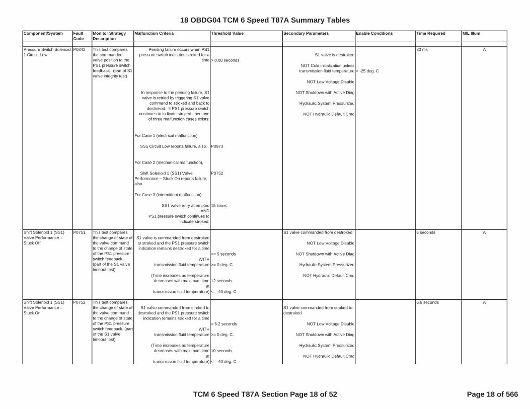
P0751 This test compares the change of state of the valve command to the change of state of the PS1 pressure switch feedback. (part of the S1 valve timeout test)
For Case 3 (intermittent malfunction),
For Case 2 (mechanical malfunction),
In response to the pending failure, S1 valve is retried by triggering S1 valve
command to stroked and back to destroked. If PS1 pressure switch
continues to indicate stroked, then one of three malfunction cases exists:
For Case 1 (electrical malfunction),
SS1 Circuit Low reports failure, also.
Shift Solenoid 1 (SS1) Valve Performance – Stuck On reports failure, also.
Pressure Switch Solenoid 1 Circuit Low
P0842 This test compares the commanded valve position to the PS1 pressure switch feedback. (part of S1 valve integrity test)
Pending failure occurs when PS1 pressure switch indicates stroked for a
time
PS1 pressure switch continues to indicate stroked.
AS1 valve is commanded from destroked to stroked and the PS1 pressure switch indication remains destroked for a time
(Time increases as temperature decreases with maximum time
A
NOT Cold initialization unless transmission fluid temperature
Shift Solenoid 1 (SS1) Valve Performance – Stuck On
P0752 This test compares the change of state of the valve command to the change of state of the PS1 pressure switch feedback. (part of the S1 valve timeout test).
AS1 valve commanded from stroked to
destroked and the PS1 pressure switch indication remains stroked for a time
S1 valve commanded from stroked to destroked
(Time increases as temperature decreases with maximum time
Shift Solenoid 1 (SS1) Valve Performance – Stuck Off
18 OBDG04 TCM 6 Speed T87A Summary Tables
TCM 6 Speed T87A Section Page 18 of 52 Page 18 of 566

Component/System Fault Code
Monitor Strategy Description
Malfunction Criteria Threshold Value Secondary Parameters Enable Conditions Time Required MIL Illum
70 msS1 valve is stroked
> 0.07 seconds
> -25 deg. C
NOT Low Voltage Disable
NOT Shutdown with Active Diag
Hydraulic System Pressurized
NOT Hydraulic Default Cmd
P0973
P0751
S1 valve retry attempted 15 times AND
40 msS2 valve is destroked
> 0.04004 seconds
> -25 deg. C
0.2998 seconds NOT Low Voltage Disable
NOT Shutdown with Active Diag
Hydraulic System Pressurized
NOT Hydraulic Default Cmd
P0976
Pressure Switch Solenoid 2 Circuit Low
P0847 This test compares the commanded valve position to the PS2 pressure switch feedback (part of the S2 valve integrity test).
Pending failure occurs when PS2 pressure switch indicates stroked for a
time
Pressure Switch Solenoid 1 Circuit High
P0843 This test compares the commanded valve position to the PS1 pressure switch feedback. (part of S1 valve integrity test)
Pending failure occurs when PS1 pressure switch indicates destroked for a
time
SS1 Control Circuit Low reports failure, also.
For Case 2 (mechanical malfunction),
PS1 pressure switch continues to indicate destroked.
A
IF a main pressure dropout is suspected then time limit increases to
In response to the pending failure, S2 valve is retried by triggering S2 valve
command to stroked and back to destroked. If PS2 pressure switch
continues to indicate stroked, then one of three malfunction cases exists.
For Case 1 (electrical malfunction),
SS2 Control Circuit Low reports failure, also.
For Case 2 (mechanical malfunction),
NOT Cold initialization unless transmission fluid temperature
A
NOT Cold initialization unless transmission fluid temperature IF a main pressure dropout is
suspected then time limit increases to 5 seconds
In response to the pending failure, S1 valve is retried by triggering S1 valve
command to destroked and back to stroked. If the PS1 pressure switch
continues to indicate destroked, then one of three malfunction cases exists.
For Case 1 (electrical malfunction),
Shift Solenoid 1 (SS1) Valve Performance – Stuck Off reports failure, also.
For Case 3 (intermittent malfunction),
18 OBDG04 TCM 6 Speed T87A Summary Tables
TCM 6 Speed T87A Section Page 19 of 52 Page 19 of 566

Component/System Fault Code
Monitor Strategy Description
Malfunction Criteria Threshold Value Secondary Parameters Enable Conditions Time Required MIL Illum
P0757
S2 valve retry attempted 2 timesAND
5 seconds
>= 5 seconds NOT Low Voltage Disable
WITHtransmission fluid temperature >= 0 deg. C. NOT Shutdown with Active Diag
Hydraulic System Pressurized12 seconds
at NOT Hydraulic Default Cmdtransmission fluid temperature) <= -40 deg. C.
6.5 sec
>= 6.5 seconds WITH NOT Low Voltage Disable
transmission fluid temperature >= 0 deg. C. NOT Shutdown with Active Diag
22 seconds Hydraulic System Pressurizedat
transmission fluid temperature) <= -40 deg. C. NOT Hydraulic Default Cmd
300 msS2 valve is stroked
> 0.30 seconds
> -25 deg. C
NOT Low Voltage Disable
NOT Shutdown with Active Diag
Hydraulic System Pressurized
NOT Hydraulic Default Cmd
P0976
P0756
Pressure Switch Solenoid 2 Circuit High
P0848 This test compares the commanded valve position to the PS2 pressure switch feedback (part of the S2 valve integrity test).
Pending failure occurs when PS2 pressure switch indicates destroked for a
time
A
NOT Cold initialization unless transmission fluid temperature IF a main pressure dropout is
suspected, THEN time limit increases to 5 seconds
In response to the pending failure, S2 valve is retried by triggering S2 valve
command to destroked and back to stroked. If PS2 pressure switch
continues to indicate destroked, then one of three malfunction cases exists.
For Case 1 (electrical malfunction),
SS2 Control Circuit Low reports failure, also.
For Case 2 (mechanical malfunction),
Shift Solenoid 2 Valve Performance – Stuck On reports failure, also.
For Case 3 (intermittent malfunction),
PS2 pressure switch continues to indicate stroked.
AS2 valve commanded from stroked to
destroked
(Time increases as temperature decreases with maximum time
Shift Solenoid 2 Valve Performance – Stuck Off
P0756 This test compares the change of state of the valve command to the change of state of the PS2 pressure switch feedback (part of the S2 valve timeout test).
If the S2 valve is commanded from destroked to stroked and the PS2
pressure switch indication remains destroked for a time
S2 valve commanded from destroked to stroked.
This test compares the commanded valve position to the PS2 pressure switch feedback (part of the S2 valve timeout test).
S2 valve commanded from stroked to destroked and the PS2 pressure switch
does not indicate destroked for a time
A
(Time increases as temperature decreases with maximum time
Shift Solenoid 2 Valve Performance – Stuck On
P0757
Shift Solenoid 2 Valve Performance –
18 OBDG04 TCM 6 Speed T87A Summary Tables
TCM 6 Speed T87A Section Page 20 of 52 Page 20 of 566
Component/System Fault Code
Monitor Strategy Description
Malfunction Criteria Threshold Value Secondary Parameters Enable Conditions Time Required MIL Illum
S2 valve retry attempted 2 timesAND
20 msS3 valve is destroked
> 0.0195 seconds
> -25 deg. C
NOT Low Voltage Disable
NOT Shutdown with Active Diag
Hydraulic System Pressurized
NOT Hydraulic Default Cmd
P0979
P0762
S3 valve retry attempted 2 timesAND
5 seconds
NOT Low Voltage Disable>= 5 seconds
WITH NOT Shutdown with Active Diagtransmission fluid temperature >= 0 deg. C.
Hydraulic System Pressurized
12 seconds NOT Hydraulic Default Cmdat
transmission fluid temperature) <= -40 deg. C.
6.6 secondsS3 valve commanded from stroked to
> 6.5 seconds NOT Low Voltage Disable WITH
PS2 pressure switch continues to indicate destroked.
Pressure Switch Solenoid 3 Circuit Low
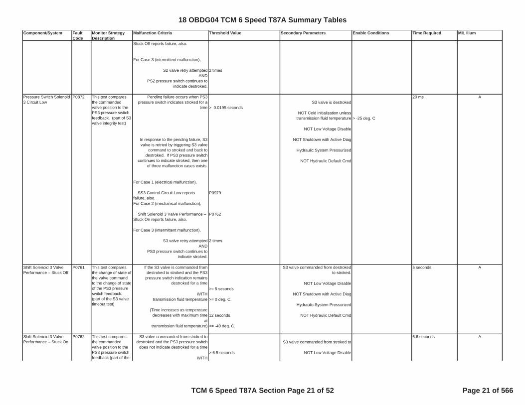
P0872 This test compares the commanded valve position to the PS3 pressure switch feedback. (part of S3 valve integrity test)
Pending failure occurs when PS3 pressure switch indicates stroked for a
time
PS3 pressure switch continues to indicate stroked.
A
NOT Cold initialization unless transmission fluid temperature
Stuck Off reports failure, also.
For Case 3 (intermittent malfunction),
In response to the pending failure, S3 valve is retried by triggering S3 valve
command to stroked and back to destroked. If PS3 pressure switch
continues to indicate stroked, then one of three malfunction cases exists.
For Case 1 (electrical malfunction),
SS3 Control Circuit Low reports failure, also.For Case 2 (mechanical malfunction),
Shift Solenoid 3 Valve Performance – Stuck On reports failure, also.
For Case 3 (intermittent malfunction),
AS3 valve commanded from stroked to destroked and the PS3 pressure switch
does not indicate destroked for a time
Shift Solenoid 3 Valve Performance – Stuck Off
P0761 This test compares the change of state of the valve command to the change of state of the PS3 pressure switch feedback. (part of the S3 valve timeout test)
If the S3 valve is commanded from destroked to stroked and the PS3
pressure switch indication remains destroked for a time
S3 valve commanded from destroked to stroked.
Shift Solenoid 3 Valve Performance – Stuck On
P0762 This test compares the commanded valve position to the PS3 pressure switch feedback (part of the
A
(Time increases as temperature decreases with maximum time
18 OBDG04 TCM 6 Speed T87A Summary Tables
TCM 6 Speed T87A Section Page 21 of 52 Page 21 of 566

Component/System Fault Code
Monitor Strategy Description
Malfunction Criteria Threshold Value Secondary Parameters Enable Conditions Time Required MIL Illum
transmission fluid temperature >= 0 deg. C. NOT Shutdown with Active Diag
22 seconds Hydraulic System Pressurized
at NOT Hydraulic Default Cmdtransmission fluid temperature) >= -40 deg. C.
300 msS3 valve is stroked
> 0.30 seconds
> -25 deg. C
NOT Low Voltage Disable
NOT Shutdown with Active Diag
Hydraulic System Pressurized
NOT Hydraulic Default Cmd
P0979
P0761
S3 valve retry attempted 2 timesAND
Pressure Switch All Cases 5 secondsReverse Circuit Low Case 1: (Forward range) P0877
For a sample size 100 samples P0878P0708
255 samplesP0708
AND
RPS indicates Reverse Components powered AND for a time >= 1 seconds Ignition Voltage between 9 V and 18 V
(if dropout suspected, NLT or N02 cmded, use time) 30 seconds Engine Speed between
Case 2: (Range indefinite) for 5 secondsFor a sample size, 20 samplesnet engine torque >= 100 Nm >= 0 deg. C
(Time increases as temperature decreases with maximum time
Pressure Switch Solenoid 3 Circuit High
P0873 This test compares the commanded valve position to the pressure switch PS3 feedback. (part of S3 valve integrity test)
Pending failure occurs when PS3 pressure switch indicates destroked for a
time
S3 valve timeout test).
Shift Solenoid 3 Valve Performance – Stuck Off reports failure, also.
For Case 3 (intermittent malfunction),
PS3 pressure switch continues to indicate destroked.
A
NOT Cold initialization unless transmission fluid temperature
SS3 Control Circuit Low reports failure, also.
For Case 2 (mechanical malfunction),
IF a main pressure dropout is suspected THEN time limit increases to 5 seconds
In response to the pending failure, S3 valve is retried by triggering S3 valve
command to destroked and back to stroked. If PS3 pressure switch
continues to indicate destroked, then one of the three malfunction cases
exists.
For Case 1 (electrical malfunction),
ANot Test Failed This Key On
(if dropout suspected, NLT or N02 cmded, use sample size)
No Fault Pending DTCs for this drive cycle PRNDL is P, D1, D2, D3, D4, D5, D6,
T8, or T4
200 RPM and 7500 RPM
Transmission Fluid Temperature
Engine had been cranking or running this drive cycle
P0877 This test detects Reverse Pressure Switch closed indication by comparing the Reverse Pressure Switch state to the PRNDL switch state.
18 OBDG04 TCM 6 Speed T87A Summary Tables
TCM 6 Speed T87A Section Page 22 of 52 Page 22 of 566

Component/System Fault Code
Monitor Strategy Description
Malfunction Criteria Threshold Value Secondary Parameters Enable Conditions Time Required MIL Illum
AND
Hydraulic System Pressurizedfor a time > 1 second
All Cases P0877P0878P0708
P0708
NOT Fault Active P0878 1.5 secondsIF Rev Gear Ratio and RPS indicates not Reverse Ignition Voltage between 9 V and 18 V
for >= 0.5 second First Range CommandedAND Engine Torque >= 100 Nm Shift Complete
for >= 1 second Output Speed >= 100 rpmreport malfunction
10 seconds Power Mode is NOT Off
If RPS indicates not Reverse >= 0 deg. C for a time > 10 seconds
at transmission fluid temperature 0 deg. C.during engine shutdown
This time varies with transmission fluid 3 seconds at transmission fluid temperature > 35 deg. C Engine speed < 50 RPM
to time 12 seconds Turbine speed < 50 RPM at transmission fluid temperature < -20 deg. C. Output speed < 50 RPM
report malfunction at Init
On-coming/Off-going 2.25 seconds
>= 2 seconds P0721 (For rough road conditions, use) 2 seconds P0722
P0716P0717P0877
output speed >= 60 RPM P0878AND commanded gear slip speed > 75 RPM P07BF (For rough road conditions, use) 150 RPM. P07C0
P077CP077D
Output Speed >= 125 RPM
ANot Test Failed This Key On
Timer accumulates when transmission is shifting,
In response of pending failure, a diagnostic response range is
commanded. During this command, this
PRNDL is indefinitely D3 or another forward range
Reverse Pressure Switch State indicates REVERSE
No range switch response active
Case 1: (RPS State and Gear Ratio do not agree)
For Case 2: (RPS Shutdown Test)
Transmission Fluid Temperature
Engine had been cranking or running this drive cycle
Pressure Control Solenoid 1 Controlled Clutch Stuck Off
P2723 This test determines if the on-coming clutch energized by Pressure Control Solenoid 1 engages during a forward range shift.
Pending failure occurs when accumulated event timer
Pressure Switch Reverse Circuit High
P0878 This test detects the Reverse Pressure switch being stuck in the open position by comparing to the PRNDL switch state and detects the Reverse Pressure switch stuck open at shutdown.
Not Test Failed This Key On A
No Fault Pending DTC for this drive cycle.
18 OBDG04 TCM 6 Speed T87A Summary Tables
TCM 6 Speed T87A Section Page 23 of 52 Page 23 of 566

Component/System Fault Code
Monitor Strategy Description
Malfunction Criteria Threshold Value Secondary Parameters Enable Conditions Time Required MIL Illum
Turbine Speed >= 60 RPM>= 250 RPM
for sample size > 10 samples Hydraulic System Pressurized
No range switch response active
No Cold Mode operation
NOT Low Voltage Disable
2.25 seconds>= 2 seconds P0721
(For rough road conditions, use) 2 seconds P0722P0716P0717P0877
output speed >= 60 RPM P0878P07BF
> 75 RPM P07C0 (For rough road conditions, use) 150 RPM. P077C
P077D
Output Speed >= 125 RPMTurbine Speed >= 60 RPM
>= 250 RPM Hydraulic System Pressurizedfor sample size > 10 samples
No range switch response active
No Cold Mode operation
test fails if ABS(Converter slip)
Normal powertrain shutdown not in process
No abusive garage shift to 1st range detected
Pressure Control Solenoid 2 Controlled Clutch Stuck Off
P0776 This test determines if the on-coming clutch energized by Pressure Control Solenoid 2 engages during a forward range shift.
Pending failure occurs when accumulated event timer
Normal or Cold powertrain initialization is complete
Power downshift abort to previous range NOT active
ANot Test Failed This Key On
Timer accumulates when transmission is shifting,
AND commanded gear slip speed
In response of pending failure, a diagnostic response range is
commanded. During this command, this test fails if ABS(Converter slip)
Normal or Cold powertrain initialization is complete
On-coming clutch control enabled
No abusive garage shift to 1st range detected
Normal powertrain shutdown not in process
On-coming clutch control enabled
18 OBDG04 TCM 6 Speed T87A Summary Tables
TCM 6 Speed T87A Section Page 24 of 52 Page 24 of 566

Component/System Fault Code
Monitor Strategy Description
Malfunction Criteria Threshold Value Secondary Parameters Enable Conditions Time Required MIL Illum
NOT Low Voltage Disable
3 secondsAccumulated fail timer >= 0.2998 seconds P0721
for forward range upshift; P0722OR accumulated fail timer >= 3.0 seconds P0716for direction change shifts; P0717OR accumulated fail timer >= 0.500 seconds P0877
P0878P07BF
OR accumulated fail timer >= 1.0 second P07C0P077CP077D
Output Speed >= 200 RPMTurbine Speed >= 200 RPM
<= 25 RPM
No range switch response active
No Cold Mode operation
NOT Low Voltage Disable
3 secondsAccumulated fail timer >= 0.2998 seconds P0721
for forward range upshift; P0722OR accumulated fail timer >= 3.0 seconds P0716for direction change shifts; P0717OR accumulated fail timer >= 0.500 seconds P0877
P0878P07BF
OR accumulated fail timer >= 1.0 second P07C0P077CP077D
Output Speed >= 200 RPMTurbine Speed >= 200 RPM
<= 25 RPM
P2724 This test determines if the off-going clutch energized by Pressure Control solenoid 1 remains engaged during a forward range shift.
ANot Test Failed This Key On
for forward range closed throttle downshift;
for forward downshifts above closed throttle.
Fail timer accumulates during range to range shifts when attained gear slip
speed
Normal or Cold powertrain initialization is complete
Power downshift abort to previous range NOT active
Pressure Control Solenoid 1 Controlled Clutch Stuck On
Pressure Control Solenoid 2 Controlled Clutch Stuck On
P0777 This test determines if the off-going clutch energized by Pressure Control solenoid 2 remains engaged during a forward range shift.
ANot Test Failed This Key On
for forward range closed throttle downshift;
for forward downshifts above closed throttle.
Fail timer accumulates during range to range shifts when attained gear slip
speed
No range switch response active
Normal or Cold powertrain initialization is complete
Normal powertrain shutdown not in process
Normal powertrain shutdown not in process
No abusive garage shift to 1st range detected
18 OBDG04 TCM 6 Speed T87A Summary Tables
TCM 6 Speed T87A Section Page 25 of 52 Page 25 of 566

Component/System Fault Code
Monitor Strategy Description
Malfunction Criteria Threshold Value Secondary Parameters Enable Conditions Time Required MIL Illum
No Cold Mode operation
NOT Low Voltage Disable
PRNDL/IMS
For Case 1 (No Information): Components powered Case 1:Illegal electrical state for a time >= 1 second AND 1 second
Battery Voltage >= 9 VFor Case 2 (Long-term Parity): Case 2:
Engine Speed between
for 5 seconds
IF Counter 1 >= 15 counts THEN report failure.
IF Counter 2, >= 5 countsTHEN report failure.
IF Counter 3, >= 5 countsTHEN report failure.
Where . . . .
>= 30 seconds;
A
There are 3 counters for long-term parity. These counters are updated at
the end of each drive cycle, immediately prior to TCM shutdown.
200 RPM and 7500 RPM 5th occurrence
For Counter 1, increment counter IF Parity Error Detected; decrement
counter IF No Parity Error Detected AND No Motion Detected.
For Counter 2, increment counter IF Parity Error Detected AND (No Valid
Drive Detected OR No Valid Park/Neutral Detected) AND Motion Detected; decrement counter IF No
Parity Error Detected AND Valid Park/Neutral Detected AND Valid Drive
Detected AND Motion Detected.
For Counter 3, increment Counter 3 IF Parity Error Detected while in Reverse AND No Valid Reverse Detected AND
Motion Detected. Decrement Counter 3 IF No Parity Error Detected AND Valid
Reverse Detected AND Motion Detected.
Transmission Range Sensor High Input
P0708 This test monitors the transmission range switch for invalid input conditions and parity errors occurring over consecutive ignition cycles.
Parity Error Detected is defined as a failure of the 4-bit PRNDL input such that the sum of those bits yields an odd result
for a time;
No abusive garage shift to 1st range detected
18 OBDG04 TCM 6 Speed T87A Summary Tables
TCM 6 Speed T87A Section Page 26 of 52 Page 26 of 566

Component/System Fault Code
Monitor Strategy Description
Malfunction Criteria Threshold Value Secondary Parameters Enable Conditions Time Required MIL Illum
>= 200 RPM for a time; >= 10 seconds
>= 3 seconds
>= 0.2 secondsand output speed; <= 20 RPM
for a time; >= 15 seconds;
for a time >= 0.2 secondsand output speed <= 20 RPM
OR for a time. >= 3 seconds
200 msFor sample size, > 7 samples P0706
Ignition voltage between 9V and 18 V
Engine speed
Solenoid Electrical
Valid Park Detected is defined as the 4-bit PRNDL indicates Valid Park for a
time
Valid Reverse Detected is defined as the 4-bit PRNDL indicates Valid Reverse
Valid Neutral Detected is defined as the 4-bit PRNDL indicates Valid Neutral
Motion Detected is defined as output speed
Valid Drive Detected is defined as the 4-bit DL indicates Valid Drive for a time;
Transmission Range Sensor Circuit Range/Performance
P0706 This test monitors the transmission range switch inputs at engine start to determine that it is indicating a valid starting position (Park or Neutral).
BNot Test Failed This Key On
PRNDL C input is closed OR PRNDL P is NOT closed.
Powertrain State is READY or CRANKING
> 100 RPM and < 350 RPM.
18 OBDG04 TCM 6 Speed T87A Summary Tables
TCM 6 Speed T87A Section Page 27 of 52 Page 27 of 566

Component/System Fault Code
Monitor Strategy Description
Malfunction Criteria Threshold Value Secondary Parameters Enable Conditions Time Required MIL Illum
A ground short condition shall be detected if the circuit attached to the Controller external connection has an impedance <= 0.01 ohm to a voltage source within the Vehicle Ground Voltage Range relative to PWRGND. The interface shall detect a ground short condition when the driver is Off. There is 10 usec fault filter. The fault is checked for every 6.25 ms by application software. An open circuit condition shall be detected if the circuit attached to the Controller external connection has an impedance >= 173 kohm and shall not be detected if the circuit impedance is <= 9.6 k ohm. The interface shall detect an open circuit condition when the driver is Off. There is 10 usec fault filter. The fault is checked for every 6.25 ms by application software.
125 ms
Not Test Failed This Key On P2669P2670
IF either hardware faults are present for >= 3 counts P2671
Components powered
IF intrusive test indicates open for >= 2 counts AND
THEN report malfunction Battery Voltage >= 9 V
If Engine Cranking, thenCrank Time < 4 seconds
ANDBattery Voltage > 10 V
Engine speed >= 20 RPM
High Side Driver 2 Enabled
1000 ms A
IF delta(desired current - actual current) >= 0.5 ampsP2669
FOR >= 40 counts P2670
For a sample size < 80 samples P2671P0960
THEN report malfunction P0961P0962
P0960P0962
Components powered AND
Battery Voltage >= 9 V
A
Main Modulation/Line Pressure Control Solenoid Control Circuit Performance
P0961 This test detects the performance of the solenoid by comparing desired current to actual duty cycle
Not Test Failed This Key On
No Fault Pending DTC for this drive cycle.
Main Modulation/Line Pressure Control Solenoid Control Circuit Open
P0960 This test detects solenoid electrical open circuit malfunctions.
Fault pending is set on a single occurrence of hardware ground or open
fault.
THEN initiate intrusive test by opening low side driver
18 OBDG04 TCM 6 Speed T87A Summary Tables
TCM 6 Speed T87A Section Page 28 of 52 Page 28 of 566

Component/System Fault Code
Monitor Strategy Description
Malfunction Criteria Threshold Value Secondary Parameters Enable Conditions Time Required MIL Illum
If Engine Cranking, thenCrank Time < 4 seconds
ANDBattery Voltage > 10 V
Engine speed >= 20 RPM
High Side Driver 2 Enabled
Shift Complete
Lockup Apply CompleteOR
Lockup Release Complete
A ground short condition shall be detected if the circuit attached to the Controller external connection has an impedance <= 0.01 ohm to a voltage source within the Vehicle Ground Voltage Range relative to PWRGND. The interface shall detect a ground short condition when the driver is Off. There is 10 usec fault filter. The fault is checked for every 6.25 ms by application software. An open circuit condition shall be detected if the circuit attached to the Controller external connection has an impedance >= 173 kohm and shall not be detected if the circuit impedance is <= 9.6 k ohm. The interface shall detect an open circuit condition when the driver is Off. There is 10 usec fault filter. The fault is checked for every 6.25 ms by application software.
125 ms
P2669P2670P2671
IF either hardware faults are present for >= 3 counts
Components powered IF intrusive test indicates grnd for >= 2 counts AND
THEN report malfunction Battery Voltage >= 9 V
If Engine Cranking, thenCrank Time < 4 seconds
ANDBattery Voltage > 10 V
Engine speed >= 20 RPM
High Side Driver 2 Enabled
Main Modulation/Line Pressure Control Solenoid Control Circuit Low
P0962 This test detects solenoid electrical ground circuit malfunctions.
A
Not Test Failed This Key On
THEN initiate intrusive test by opening low side driver
Fault pending is set on a single occurrence of hardware ground or open
fault.
18 OBDG04 TCM 6 Speed T87A Summary Tables
TCM 6 Speed T87A Section Page 29 of 52 Page 29 of 566
Component/System Fault Code
Monitor Strategy Description
Malfunction Criteria Threshold Value Secondary Parameters Enable Conditions Time Required MIL Illum
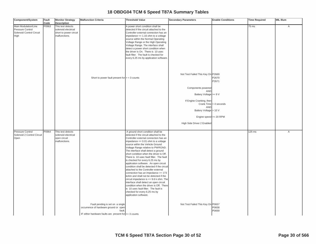
A power short condition shall be detected if the circuit attached to the Controller external connection has an impedance <= 1.16 ohm to a voltage source within the Normal Operating Voltage Range or the High Operating Voltage Range. The interface shall detect a power short condition when the driver is On. There is 10 usec fault filter. The fault is checked for every 6.25 ms by application software.
75 ms
P2669Short to power fault present for > = 3 counts P2670
P2671
Components powered AND
Battery Voltage >= 9 V
If Engine Cranking, thenCrank Time < 4 seconds
ANDBattery Voltage > 10 V
Engine speed >= 20 RPM
High Side Driver 2 Enabled
A ground short condition shall be detected if the circuit attached to the Controller external connection has an impedance <= 0.01 ohm to a voltage source within the Vehicle Ground Voltage Range relative to PWRGND. The interface shall detect a ground short condition when the driver is Off. There is 10 usec fault filter. The fault is checked for every 6.25 ms by application software. An open circuit condition shall be detected if the circuit attached to the Controller external connection has an impedance >= 173 kohm and shall not be detected if the circuit impedance is <= 9.6 k ohm. The interface shall detect an open circuit condition when the driver is Off. There is 10 usec fault filter. The fault is checked for every 6.25 ms by application software.
125 ms
P0657P0658P0659
IF either hardware faults are present for >= 3 counts
Pressure Control Solenoid 2 Control Circuit Open
P0964 This test detects solenoid electrical open circuit malfunctions.
A
Not Test Failed This Key On
Main Modulation/Line Pressure Control Solenoid Control Circuit High
P0963 This test detects solenoid electrical short to power circuit malfunctions.
A
Not Test Failed This Key On
Fault pending is set on a single occurrence of hardware ground or open
fault.
18 OBDG04 TCM 6 Speed T87A Summary Tables
TCM 6 Speed T87A Section Page 30 of 52 Page 30 of 566

Component/System Fault Code
Monitor Strategy Description
Malfunction Criteria Threshold Value Secondary Parameters Enable Conditions Time Required MIL Illum
Components powered AND
IF intrusive test indicates open for >= 2 counts Battery Voltage >= 9 VTHEN report malfunction
If Engine Cranking, thenCrank Time < 4 seconds
ANDBattery Voltage > 10 V
Engine speed >= 20 RPM
High Side Driver 1 Enabled
250ms AP0657
IF delta(desired current - actual current) >= 0.5 amps P0658FOR >= 10 counts P0659
P0964For a sample size < 20 samples P0965
P0966THEN report malfunction
P0964P0966
Components powered AND
Battery Voltage >= 9 V
If Engine Cranking, thenCrank Time < 4 seconds
AND
Battery Voltage > 10 V
Engine speed >= 20 RPM
High Side Driver 1 Enabled
Shift Complete
Lockup Apply CompleteOR
Lockup Release Complete
THEN initiate intrusive test by opening low side driver
Pressure Control Solenoid 2 Control Circuit Performance
P0965 This test detects the performance of the solenoid by comparing desired current to actual duty cycle
Not Test Failed This Key On
No Fault Pending DTC for this drive cycle.
18 OBDG04 TCM 6 Speed T87A Summary Tables
TCM 6 Speed T87A Section Page 31 of 52 Page 31 of 566

Component/System Fault Code
Monitor Strategy Description
Malfunction Criteria Threshold Value Secondary Parameters Enable Conditions Time Required MIL Illum
A ground short condition shall be detected if the circuit attached to the Controller external connection has an impedance <= 0.01 ohm to a voltage source within the Vehicle Ground Voltage Range relative to PWRGND. The interface shall detect a ground short condition when the driver is Off. There is 10 usec fault filter. The fault is checked for every 6.25 ms by application software. An open circuit condition shall be detected if the circuit attached to the Controller external connection has an impedance >= 173 kohm and shall not be detected if the circuit impedance is <= 9.6 k ohm. The interface shall detect an open circuit condition when the driver is Off. There is 10 usec fault filter. The fault is checked for every 6.25 ms by application software.
125 ms
P0657P0658P0659
IF either hardware faults are present for >= 3 counts
IF intrusive test indicates grnd for >= 2 countsTHEN report malfunction Components powered
ANDBattery Voltage >= 9 V
If Engine Cranking, thenCrank Time < 4 seconds
ANDBattery Voltage > 10 V
Engine speed >= 20 RPM
High Side Driver 1 Enabled
A power short condition shall be detected if the circuit attached to the Controller external connection has an impedance <= 1.16 ohm to a voltage source within the Normal Operating Voltage Range or the High Operating Voltage Range. The interface shall detect a power short condition when the driver is On. There is 10 usec fault filter. The fault is checked for every 6.25 ms by application software.
75 ms
P0657Short to power fault present for > = 3 counts P0658
P0659P0967
Pressure Control Solenoid 2 Control Circuit Low
P0966 This test detects solenoid electrical ground circuit malfunctions.
THEN initiate intrusive test by opening low side driver
A
Not Test Failed This Key On
Pressure Control Solenoid 2 Control Circuit High
P0967 This test detects solenoid electrical short to power circuit malfunctions.
A
Not Test Failed This Key On
Fault pending is set on a single occurrence of hardware ground or open
fault.
18 OBDG04 TCM 6 Speed T87A Summary Tables
TCM 6 Speed T87A Section Page 32 of 52 Page 32 of 566

Component/System Fault Code
Monitor Strategy Description
Malfunction Criteria Threshold Value Secondary Parameters Enable Conditions Time Required MIL Illum
Components powered AND
Battery Voltage >= 9 V
If Engine Cranking, thenCrank Time < 4 seconds
ANDBattery Voltage > 10 V
Engine speed >= 20 RPM
High Side Driver 1 EnabledHigh Side Driver 1 Enabled
A ground short condition shall be detected if the circuit attached to the Controller external connection has an impedance <= 0.01 ohm to a voltage source within the Vehicle Ground Voltage Range relative to PWRGND. The interface shall detect a ground short condition when the driver is Off. There is 10 usec fault filter. The fault is checked for every 6.25 ms by application software. An open circuit condition shall be detected if the circuit attached to the Controller external connection has an impedance >= 173 kohm and shall not be detected if the circuit impedance is <= 9.6 k ohm. The interface shall detect an open circuit condition when the driver is Off. There is 10 usec fault filter. The fault is checked for every 6.25 ms by application software.
125 ms
P2669P2670P2671
IF either hardware faults are present for >= 3 countsComponents powered
ANDIF intrusive test indicates open for >= 2 counts Battery Voltage >= 9 V
THEN report malfunctionIf Engine Cranking, then
Crank Time < 4 secondsAND
Battery Voltage > 10 V
Engine speed >= 20 RPM
High Side Driver 2 Enabled
250 ms AIF delta(desired current - actual current) >= 0.5 amps P2669
FOR >= 10 counts P2670For a sample size < 20 samples P2671
P2727THEN report malfunction P2728
Pressure Control Solenoid 1 Control Circuit Open
P2727 This test detects solenoid electrical open circuit malfunctions.
A
Not Test Failed This Key OnFault pending is set on a single occurrence of hardware ground or open
fault.
THEN initiate intrusive test by opening low side driver
Pressure Control Solenoid 1 Control Circuit Performance
P2728 This test detects the performance of the solenoid by comparing desired current to actual duty cycle
Not Test Failed This Key On
18 OBDG04 TCM 6 Speed T87A Summary Tables
TCM 6 Speed T87A Section Page 33 of 52 Page 33 of 566

Component/System Fault Code
Monitor Strategy Description
Malfunction Criteria Threshold Value Secondary Parameters Enable Conditions Time Required MIL Illum
P2729
P2727P2729
Components powered AND
Battery Voltage >= 9 V
If Engine Cranking, thenCrank Time < 4 seconds
ANDBattery Voltage > 10 V
Engine speed >= 20 RPM
High Side Driver 2 Enabled
Shift Complete
Lockup Apply CompleteOR
Lockup Release Complete
A ground short condition shall be detected if the circuit attached to the Controller external connection has an impedance <= 0.01 ohm to a voltage source within the Vehicle Ground Voltage Range relative to PWRGND. The interface shall detect a ground short condition when the driver is Off. There is 10 usec fault filter. The fault is checked for every 6.25 ms by application software. An open circuit condition shall be detected if the circuit attached to the Controller external connection has an impedance >= 173 kohm and shall not be detected if the circuit impedance is <= 9.6 k ohm. The interface shall detect an open circuit condition when the driver is Off. There is 10 usec fault filter. The fault is checked for every 6.25 ms by application software.
125 ms
P2669P2670P2671
IF either hardware faults are present for >= 3 counts Components powered AND
Battery Voltage >= 9 V IF intrusive test indicates grnd for >= 2 counts
THEN report malfunction If Engine Cranking, thenCrank Time < 4 seconds
ANDBattery Voltage > 10 V
No Fault Pending DTC for this drive cycle.
Pressure Control Solenoid 1 Control Circuit Low
P2729 This test detects solenoid electrical ground circuit malfunctions.
Fault pending is set on a single occurrence of hardware ground or open
fault.
THEN initiate intrusive test by opening low side driver
A
Not Test Failed This Key On
18 OBDG04 TCM 6 Speed T87A Summary Tables
TCM 6 Speed T87A Section Page 34 of 52 Page 34 of 566
Component/System Fault Code
Monitor Strategy Description
Malfunction Criteria Threshold Value Secondary Parameters Enable Conditions Time Required MIL Illum
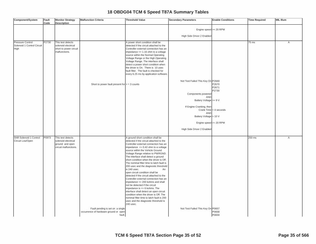
Engine speed >= 20 RPM
High Side Driver 2 Enabled
A power short condition shall be detected if the circuit attached to the Controller external connection has an impedance <= 1.16 ohm to a voltage source within the Normal Operating Voltage Range or the High Operating Voltage Range. The interface shall detect a power short condition when the driver is On. There is 10 usec fault filter. The fault is checked for every 6.25 ms by application software.
75 ms
P2669Short to power fault present for > = 3 counts P2670
P2671P2730
Components powered AND
Battery Voltage >= 9 V
If Engine Cranking, thenCrank Time < 4 seconds
ANDBattery Voltage > 10 V
Engine speed >= 20 RPM
High Side Driver 2 Enabled
A ground short condition shall be detected if the circuit attached to the Controller external connection has an impedance <= 0.42 ohm to a voltage source within the Vehicle Ground Voltage Range relative to PWRGND. The interface shall detect a ground short condition when the driver is Off. The nominal filter time to latch fault is 200 usec and the diagnostic threshold is 240 usec. An open circuit condition shall be detected if the circuit attached to the Controller external connection has an impedance >= 200 kohms and shall not be detected if the circuit impedance is <= 6 kohms. The interface shall detect an open circuit condition when the driver is Off. The nominal filter time to latch fault is 200 usec and the diagnostic threshold is 240 usec.
250 ms
P0657P0658P0659
Pressure Control Solenoid 1 Control Circuit High
P2730 This test detects solenoid electrical short to power circuit malfunctions.
A
Not Test Failed This Key On
Shift Solenoid 1 Control Circuit Low/Open
P0973 This test detects solenoid electrical ground and open circuit malfunctions.
A
Not Test Failed This Key OnFault pending is set on a single occurrence of hardware ground or open
fault.
18 OBDG04 TCM 6 Speed T87A Summary Tables
TCM 6 Speed T87A Section Page 35 of 52 Page 35 of 566

Component/System Fault Code
Monitor Strategy Description
Malfunction Criteria Threshold Value Secondary Parameters Enable Conditions Time Required MIL Illum
IF either hardware fault is present for >= 10 countsTHEN report malfunction Components powered
ANDBattery Voltage >= 9 V
If Engine Cranking, thenCrank Time < 4 seconds
ANDBattery Voltage > 10 V
Engine speed >= 20 RPM
High Side Driver 1 Enabled
A power short condition shall be detected if the circuit attached to the Controller external connection has an impedance <= 0.39 ohm to a voltage source within the Normal Operating Voltage Range or the High Operating Voltage Range. The interface shall detect a power short condition when the driver is On. The nominal filter time to latch fault is 150 usec and the diagnostic threshold is 240 usec.
75 ms
P0657Short to power fault present for > = 3 counts P0658
P0659P0974
Components powered AND
Battery Voltage >= 9 V
If Engine Cranking, thenCrank Time < 4 seconds
ANDBattery Voltage > 10 V
Engine speed >= 20 RPM
High Side Driver 1 Enabled
Shift Solenoid 1 Control Circuit High
P0974 This test detects solenoid electrical short to power circuit malfunctions.
A
Not Test Failed This Key On
18 OBDG04 TCM 6 Speed T87A Summary Tables
TCM 6 Speed T87A Section Page 36 of 52 Page 36 of 566

Component/System Fault Code
Monitor Strategy Description
Malfunction Criteria Threshold Value Secondary Parameters Enable Conditions Time Required MIL Illum
A ground short condition shall be detected if the circuit attached to the Controller external connection has an impedance <= 0.42 ohm to a voltage source within the Vehicle Ground Voltage Range relative to PWRGND. The interface shall detect a ground short condition when the driver is Off. The nominal filter time to latch fault is 200 usec and the diagnostic threshold is 240 usec. An open circuit condition shall be detected if the circuit attached to the Controller external connection has an impedance >= 200 kohms and shall not be detected if the circuit impedance is <= 6 kohms. The interface shall detect an open circuit condition when the driver is Off. The nominal filter time to latch fault is 200 usec and the diagnostic threshold is 240 usec.
250 ms
P0657P0658P0659
IF either hardware fault is present for >= 10 countsTHEN report malfunction
Components powered AND
Battery Voltage >= 9 V
If Engine Cranking, thenCrank Time < 4 seconds
ANDBattery Voltage > 10 V
Engine speed >= 20 RPM
High Side Driver 1 Enabled
A power short condition shall be detected if the circuit attached to the Controller external connection has an impedance <= 0.39 ohm to a voltage source within the Normal Operating Voltage Range or the High Operating Voltage Range. The interface shall detect a power short condition when the driver is On. The nominal filter time to latch fault is 150 usec and the diagnostic threshold is 240 usec.
75 ms
P0657Short to power fault present for > = 3 counts P0658
P0659P0977
Components powered
A
Not Test Failed This Key On
Shift Solenoid 2 Control Circuit High
P0977 This test detects solenoid electrical short to power circuit malfunctions.
A
Not Test Failed This Key On
Shift Solenoid 2 Control Circuit Low/Open
P0976 This test detects solenoid electrical ground or open circuit malfunctions.
Fault pending is set on a single occurrence of hardware ground
18 OBDG04 TCM 6 Speed T87A Summary Tables
TCM 6 Speed T87A Section Page 37 of 52 Page 37 of 566

Component/System Fault Code
Monitor Strategy Description
Malfunction Criteria Threshold Value Secondary Parameters Enable Conditions Time Required MIL Illum
ANDBattery Voltage >= 9 V
If Engine Cranking, thenCrank Time < 4 seconds
ANDBattery Voltage > 10 V
Engine speed >= 20 RPM
High Side Driver 1 Enabled
A ground short condition shall be detected if the circuit attached to the Controller external connection has an impedance <= 0.22 ohm to a voltage source within the Vehicle Ground Voltage Range relative to PWRGND. The interface shall detect a ground short condition when the driver is Off . The nominal filter time to latch fault is 200 usec and the diagnostic threshold is 240 usec. An open circuit condition shall be detected if the circuit attached to the Controller external connection has an impedance >= 200 kohms and shall not be detected if the circuit impedance is <= 6 kohms. The interface shall detect an open circuit condition when the driver is Off. The nominal filter time to latch fault is 200 usec and the diagnostic threshold is 240 usec.
250 ms
P0657P0658P0659
IF either hardware fault is present for >= 10 counts P0979THEN report malfunction
Components powered AND
Battery Voltage >= 9 V
If Engine Cranking, thenCrank Time < 4 seconds
ANDBattery Voltage > 10 V
Engine speed >= 20 RPM
High Side Driver 1 Enabled
Shift Solenoid 3 Control Circuit Low/Open
P0979 This test detects solenoid electrical ground or open circuit malfunctions.
A
Not Test Failed This Key OnFault pending is set on a single occurrence of hardware ground or open
fault.
18 OBDG04 TCM 6 Speed T87A Summary Tables
TCM 6 Speed T87A Section Page 38 of 52 Page 38 of 566

Component/System Fault Code
Monitor Strategy Description
Malfunction Criteria Threshold Value Secondary Parameters Enable Conditions Time Required MIL Illum
A power short condition shall be detected if the circuit attached to the Controller external connection has an impedance <= 0.39 ohm to a voltage source within the Normal Operating Voltage Range or the High Operating Voltage Range. The interface shall detect a power short condition when the driver is On. The nominal filter time to latch fault is 150 usec and the diagnostic threshold is 240 usec.
75 ms
Short to power fault present for > = 3 counts P0657P0658P0659P0980
Components powered AND
Battery Voltage >= 9 V
If Engine Cranking, thenCrank Time < 4 seconds
ANDBattery Voltage > 10 V
Engine speed >= 20 RPM
High Side Driver 1 Enabled
75 msIF HSD1 fault is indeterminate P0657
THEN initiate intrusive testCommand intrusive gear. HSD1 is commanded ON
Override pressure control solenoid 2 >= 0.075 secTHEN exit intrusive test after > 0.050 sec Components powered
ANDBattery Voltage >= 9 V
>= 3If Engine Cranking, then
Crank Time < 4 secondsAND
>= 2 Battery Voltage > 10 V
Engine speed >= 20 RPM
Shift Solenoid 3 Control Circuit High
P0980 This test detects solenoid electrical short to power circuit malfunctions.
A
Not Test Failed This Key On
A failure event occurs when the number of failed solenoids connected to HSD1
Actuator Supply 1 (HSD1) Voltage Open
P0657 This test detects if the voltage measured at the HSD1 detection circuit shows that multiple low side detection circuits indicate open, but the high side detection circuit indicates high voltage.
ANot Test Failed This Key On
Report malfunction when the number of failure events
18 OBDG04 TCM 6 Speed T87A Summary Tables
TCM 6 Speed T87A Section Page 39 of 52 Page 39 of 566

Component/System Fault Code
Monitor Strategy Description
Malfunction Criteria Threshold Value Secondary Parameters Enable Conditions Time Required MIL Illum
A ground short condition shall be detected if the circuit attached to the Controller external connection has an impedance <= 0.43 ohm to a voltage source within the Vehicle Ground Voltage Range relative to PWRGND. The interface shall detect a ground short condition when the driver is On. Ground short is read every 10 us (fault filtering). Diagnostic time is 50 usec - every 50us (5 readings) with a minimum of 3 readings out of 5 to flag a short.
75 ms
P0658
>= 3 times HSD1 is commanded ON
A power short condition shall be detected if the circuit attached to the Controller external connection has an impedance <= 0.5 ohm to a voltage source within the Normal Operating Voltage Range or the High Operating Voltage Range. The interface shall detect a power short condition when the driver is Off. Power short is read every 10 us after power up reset (fault filtering). Diagnostic time is 50 usec - every 50us (5 readings) with a minimum of 3 readings out of 5.
18.75 ms
During initialization>= 3 times
Battery Voltage >= 9V
75 msP2669
>= 3HSD2 is commanded ON
>= 2 Components powered
ANDBattery Voltage >= 9 V
If Engine Cranking, thenCrank Time < 4 seconds
ANDBattery Voltage > 10 V
Engine Speed >= 20 rpm
Actuator Supply 1 (HSD1) Voltage Low
P0658 This test detects low voltage when high voltage is expected indicating a short to ground at the circuit.
A
Report malfunction when short to ground is detected for a number of events
Not Test Failed This Key On
During initialization, report malfunction when the number of failure events
Actuator Supply2 (HSD2) Voltage Open
P2669 This test detects if the voltage measured at the HSD2 detection circuit shows that multiple low side detection circuits indicate open, but the high side detection circuit indicates high voltage.
ANot Test Failed This Key On
A failure event occurs when the number of failed solenoids connected to HSD1
Report malfunction when the number of failure events
Actuator Supply 1 (HSD1) Voltage High
P0659 This test detects if the voltage measured at the HSD 1 detection circuit indicates high during initialization (when the circuit is off)
A
18 OBDG04 TCM 6 Speed T87A Summary Tables
TCM 6 Speed T87A Section Page 40 of 52 Page 40 of 566

Component/System Fault Code
Monitor Strategy Description
Malfunction Criteria Threshold Value Secondary Parameters Enable Conditions Time Required MIL Illum
A ground short condition shall be detected if the circuit attached to the Controller external connection has an impedance <= 0.43 ohm to a voltage source within the Vehicle Ground Voltage Range relative to PWRGND. The interface shall detect a ground short condition when the driver is On. Ground short is read every 10 us (fault filtering). Diagnostic time is 50 usec - every 50us (5 readings) with a minimum of 3 readings out of 5 to flag a short.
75 ms
P2670
>= 3 times HSD2 is commanded ON
A power short condition shall be detected if the circuit attached to the Controller external connection has an impedance <= 0.5 ohm to a voltage source within the Normal Operating Voltage Range or the High Operating Voltage Range. The interface shall detect a power short condition when the driver is Off. Power short is read every 10 us after power up reset (fault filtering). Diagnostic time is 50 usec - every 50us (5 readings) with a minimum of 3 readings out of 5.
18.75 ms
During initialization>= 3 times
Battery Voltage >= 9
Actuator Supply 2 (HSD2) Voltage High
P2671 This test detects if the voltage measured at the HSD 2 detection circuit indicates high during initialization (when the circuit is off)
A
During initialization, report malfunction when the number of failure events
Actuator Supply2 (HSD2) Voltage Low
P2670 This test detects low voltage when high voltage is expected indicating a short to ground at the circuit.
A
Report malfunction when short to ground is detected for a number of events
Not Test Failed This Key On
18 OBDG04 TCM 6 Speed T87A Summary Tables
TCM 6 Speed T87A Section Page 41 of 52 Page 41 of 566

Component/System Fault Code
Monitor Strategy Description
Malfunction Criteria Threshold Value Secondary Parameters Enable Conditions Time Required MIL Illum
A ground short condition shall be detected if the circuit attached to the Controller external connection has an impedance <= 0.01 ohm to a voltage source within the Vehicle Ground Voltage Range relative to PWRGND. The interface shall detect a ground short condition when the driver is Off. There is 10 usec fault filter. The fault is checked for every 6.25 ms by application software. An open circuit condition shall be detected if the circuit attached to the Controller external connection has an impedance >= 173 kohm and shall not be detected if the circuit impedance is <= 9.6 k ohm. The interface shall detect an open circuit condition when the driver is Off. There is 10 usec fault filter. The fault is checked for every 6.25 ms by application software.
125 ms
P2669P2670P2671
IF either hardware faults are present for >= 3 countsComponents powered
ANDIF intrusive test indicates open for >= 2 counts Battery Voltage >= 9 V
THEN report malfunctionIf Engine Cranking, then
Crank Time < 4 secondsAND
Battery Voltage > 10 V
Engine Speed >= 20 rpm
High Side Driver 2 Enabled
1000 ms BIF delta(desired current - actual current) >= 0.5 amps P2669
FOR >= 40 counts P2670For a sample size < 80 samples P2671
P2761THEN report malfunction P2762
P2764
P2761P2763
Components powered AND
Battery Voltage >= 9 V
If Engine Cranking, thenCrank Time < 4 seconds
AND
Fault pending is set on a single occurrence of hardware ground or open
fault.
THEN initiate intrusive test by opening low side driver
TCC Pressure Control Solenoid Control Circuit Performance
P2762 This test detects the performance of the solenoid by comparing desired current to actual duty cycle
Not Test Failed This Key On
No Fault Pending DTC for this drive cycle.
TCC Pressure Control Solenoid Control Circuit Open
P2761 This test detects torque converter solenoid electrical open circuit malfunctions.
Not Test Failed This Key On
B
18 OBDG04 TCM 6 Speed T87A Summary Tables
TCM 6 Speed T87A Section Page 42 of 52 Page 42 of 566

Component/System Fault Code
Monitor Strategy Description
Malfunction Criteria Threshold Value Secondary Parameters Enable Conditions Time Required MIL Illum
Battery Voltage > 10 V
Engine Speed >= 20 rpm
High Side Driver 2 Enabled
Shift Complete
Lockup Apply CompleteOR
Lockup Release Complete
A power short condition shall be detected if the circuit attached to the Controller external connection has an impedance <= 1.16 ohm to a voltage source within the Normal Operating Voltage Range or the High Operating Voltage Range. The interface shall detect a power short condition when the driver is On. There is 10 usec fault filter. The fault is checked for every 6.25 ms by application software.
75 ms
P2669Short to power fault present for > = 3 counts P2670
P2671P2763
Components powered AND
Battery Voltage >= 9 V
If Engine Cranking, thenCrank Time < 4 seconds
ANDBattery Voltage > 10 V
Engine Speed >= 20 rpm
High Side Driver 2 Enabled
TCC Pressure Control Solenoid Control Circuit High
P2763 This test detects solenoid electrical short to power circuit malfunctions.
Not Test Failed This Key On
B
18 OBDG04 TCM 6 Speed T87A Summary Tables
TCM 6 Speed T87A Section Page 43 of 52 Page 43 of 566

Component/System Fault Code
Monitor Strategy Description
Malfunction Criteria Threshold Value Secondary Parameters Enable Conditions Time Required MIL Illum
A ground short condition shall be detected if the circuit attached to the Controller external connection has an impedance <= 0.01 ohm to a voltage source within the Vehicle Ground Voltage Range relative to PWRGND. The interface shall detect a ground short condition when the driver is Off. There is 10 usec fault filter. The fault is checked for every 6.25 ms by application software. An open circuit condition shall be detected if the circuit attached to the Controller external connection has an impedance >= 173 kohm and shall not be detected if the circuit impedance is <= 9.6 k ohm. The interface shall detect an open circuit condition when the driver is Off. There is 10 usec fault filter. The fault is checked for every 6.25 ms by application software.
125 ms
P2669P2670P2671
IF either hardware faults are present for >= 3 countsComponents powered
ANDIF intrusive test indicates grnd for >= 2 counts Battery Voltage >= 9 V
THEN report malfunctionIf Engine Cranking, then
Crank Time < 4 secondsAND
Battery Voltage > 10 V
Engine Speed >= 20 rpm
High Side Driver 2 Enabled
MiscellaneousCase 1 (Stuck Off) All Cases 0.5 second
P2771>= 1 P0721
P0722P077C
>= 0.5 second P077D
P2771P0721P0722P077CP077D
Case 2 (Stuck On) P0721P0722
>= 1 P077CP077D
TCC Pressure Control Solenoid Control Circuit Low
P2764 This test detects solenoid electrical ground circuit malfunctions.
B A
Not Test Failed This Key OnFault pending is set on a single occurrence of hardware ground or open
fault.
THEN initiate intrusive test by opening low side driver
B This test fails when, for number of
occurrences,Not Test Failed This Key On
No Fault Active DTCs for this drive cycle
No Fault Pending DTCs for this drive cycle
the transfer case 4WD switch indicates High range and the calculated transfer
case range is Low range for a time
This test fails when, for number of occurrences,
4 Wheel Drive Low Switch Circuit Malfunction
P2771 This test detects abnormal conditions for the four-wheel drive indication switch input by comparing switch state range to calculated range.
18 OBDG04 TCM 6 Speed T87A Summary Tables
TCM 6 Speed T87A Section Page 44 of 52 Page 44 of 566

Component/System Fault Code
Monitor Strategy Description
Malfunction Criteria Threshold Value Secondary Parameters Enable Conditions Time Required MIL Illum
NOT Tranfer Case failure suspect
>= 0.5 second Transfer Case is NOT Neutral or defaulted
Transmission fluid temperature
Engine Speed between
for 5 secondsShift complete AND
range attained NOT Neutral
8075 ms Components powered
>= 3 AND then report fail Battery Voltage >= 9 V
Engine Speed between
for 5 seconds
AND turbine speed > 50 RPM
for a time > 3 seconds.
5 secondsIgnition voltage < 5 volts P2534
THEN increment fail counterIF fail counter >= 800 counts Components powered
ANDBattery Voltage >= 9 V
Engine Speed betweenTHEN report malfunction
for 5 seconds
CAN Hardware Circuitry Detects a Bus Voltage Error (CAN bus off) = TRUE (Boolean) >= 5 counts B
>= 0.16 sec >= 5 counts all conditions A and (B or C) below
must occur for stabilization timeBus Stabilization time >= 5 seconds
A) Service mode $04 active and end of trip pocessing active = FALSE (Boolean)
A) normal serial data communication enabled = TRUE (Boolean)
A) U0073 status not = fault activeB) secured controller or emission critical then use ignition voltage
= CeCANR_e_OBDII_Dsbl (Boolean)
B) secured controller or emission critical Ignition Voltage >= 11 volts
B) Power Mode = Run
the transfer case 4WD switch indicates Low range and the calculated transfer
case range is High range for a time
> 20 deg. C and < 130 deg. C
200 RPM and 7500 RPM
Transmission Component Slipping
P0894 This test detects the number of turbine slip events during the Neutral Locked Turbine (NLT) request from engine controller.
For this ignition cycle, when the number of Neutral Locked Turbine (NLT) Slip
events,
GMLAN Bus Reset Counter Overrun
And, where number of accumulated NLT Slip events is incremented when
commanded gear or attained gear is NLT
Ignition Switch Run/Start Circuit
P2534 Out of range low.
Where number of NLT Slip events for this ignition cycle = Number of
accumulated NLT Slip events – Number of NLT Slip events from previous ignition
cycles.
U0073 This test detects if the GMLAN bus is off for a calibration duration.
AND(BattChargeSysStable TRUE OR NOT
P0882)
Bus off delay time (use if Bus if Off from Bus Indeterminate State)
200 RPM and 7500 RPM
ANot Test Failed This Key On
200 RPM and 7500 RPM
B
18 OBDG04 TCM 6 Speed T87A Summary Tables
TCM 6 Speed T87A Section Page 45 of 52 Page 45 of 566

Component/System Fault Code
Monitor Strategy Description
Malfunction Criteria Threshold Value Secondary Parameters Enable Conditions Time Required MIL Illum
C) ignition off enable = TRUE (Boolean)C) Power Mode = accessory
C) battery voltage >11 volts
GMLAN ECM Controller State of Health Failure U0100 TCM Rx message missed frame
fail times are caculated based on Rx message enable calibration set to
CeCANR e BusA ECMTx controller B
TCM Rx frame message missed frame = TRUE (Boolean) TCM Rx frame calibration enabled ( see Table 1 in supporting document) enumeration >= 10 seconds
Frame recovery stabilization delay >= 0.4 secondsall conditions A and (B or C) below
must occur for stabilization timeBus Stabilization time >= 5 seconds
A) Service mode $04 active and end of trip pocessing active = FALSE (Boolean)
A) normal serial data communication enabled = TRUE (Boolean)
A) U0073 status not = fault activeB) secured controller or emission critical then use ignition voltage
= CeCANR_e_OBDII_Dsbl (Boolean)
B) secured controller or emission critical Ignition Voltage >= 11 volts
B) Power Mode = Run
C) ignition off enable = TRUE (Boolean)C) Power Mode =accessory
C) battery voltage >11 volts
U0100 fault status is not = fault activeNot Test Failed This Key On U0073
Lost Communication with GMLAN ABS Control Module
U0121TCM Rx message missed frame
fail times are caculated based on Rx message enable calibration set to
CeCANR_e_BusA_ABSTx controller
C
TCM Rx frame message missed frame = TRUE (Boolean) TCM Rx frame calibration enabled ( see Table 1 in supporting document) enumeration >= 10 seconds
Frame recovery stabilization delay >= 0.4 secondsall conditions A and (B or C) below
must occur for stabilization timeBus Stabilization time >= 5 seconds
A) Service mode $04 active and end of trip pocessing active = FALSE (Boolean)
A) normal serial data communication enabled = TRUE (Boolean)
A) P0073 status not = fault activeB) secured controller or emission critical then use ignition voltage
= CeCANR_e_OBDII_Dsbl (Boolean)
B) secured controller or emission critical Ignition Voltage >= 11 volts
B) Power Mode = Run
C) ignition off enable = TRUE (Boolean)C) Power Mode =accessory
C) battery voltage > 11 volts
U0121 fault status is not = fault active
Not Test Failed This Key On U0073
This test detects GMLANbus failures by detecting State of Health failures in GMLAN messages $191, $0BE, $0C9,$1A1, $287, $2C3, $3B9, $3D1,$3E9, $3F9, $4C1, and $4F1 from ECM.
This test detects CAN (GMLAN) bus failures by detecting State of Health (SOH) failures in the following GMLAN messages $0C1, $0C5, $0D0, $1E9, and $2F9 from Antilock Brake System (ABS) Control Module.
18 OBDG04 TCM 6 Speed T87A Summary Tables
TCM 6 Speed T87A Section Page 46 of 52 Page 46 of 566

Component/System Fault Code
Monitor Strategy Description
Malfunction Criteria Threshold Value Secondary Parameters Enable Conditions Time Required MIL Illum
Lost Communication With Body Control Module
U0140
TCM Rx message missed framefail times are caculated based on Rx
message enable calibration set to CeCANR_e_BusA_BCM
Tx controller
C
TCM Rx frame message missed frame = TRUE (Boolean) TCM Rx frame calibration enabled ( see Table 1 in supporting document) enumeration >= 10 seconds
Frame recovery stabilization delay >= 0.4 secondsall conditions A and (B or C) below
must occur for stabilization timeBus Stabilization time >= 5 seconds
A) Service mode $04 active and end of trip pocessing active = FALSE (Boolean)
A) normal serial data communication enabled = TRUE (Boolean)
A) P0073 status not = fault activeB) secured controller or emission critical then use ignition voltage
= CeCANR_e_OBDII_Dsbl (Boolean)
B) secured controller or emission critical Ignition Voltage >= 11 volts
B) Power Mode = Run
C) ignition off enable = TRUE (Boolean)C) Power Mode =accessory
C) battery voltage >11 volts
U0140 fault status is not = fault activeNot Test Failed This Key On U0073
Case1: All Cases 10 Acceleration Events C
NOT Test Failed This Key On P0571>= 10 P0716
P0717Case 2: P07BF
P07C0>= 10
No Fault Pending DTCs P0721P0722P077CP077D
Not Fault Active P0703 10 Deceleration Events
Components powered AND
Battery Voltage >= 9 V
Engine Speed between 200 RPM and 7500 RPM
for 5 seconds
15 seconds CComponents powered
ANDBattery Voltage between 9 V and 18 V
Engine Speed betweenWhen the failure counter is > 5
for a time of > 10 seconds for 5 secondsReport Failure
This test detects CAN (GMLAN) bus failures by detecting State of Health (SOH) failures in the following GMLAN messages $0F1, $1E1, $1F3, and $3F1 from the Truck Body Computer (TBC) Control
Brake Pedal Possition Switch Signal Rolling Count
P0703 This test detects rolling count failures for the Brake Switch GMLAN Message
The failure count increments when the GMLAN message is not received or the
rolling counter does not agree with the expected value
200 RPM and 7500 RPM
The number of vehicle decelerations with the brake switch "off"
Brake Switch Circuit P0571 This test counts how many vehicle acceleration events occur while the brake switch indicates "ON" or the number of vehicle deceleration events while the brake switch indicates "OFF"
The number of vehicle accelerations with the brake switch "on"
18 OBDG04 TCM 6 Speed T87A Summary Tables
TCM 6 Speed T87A Section Page 47 of 52 Page 47 of 566

Component/System Fault Code
Monitor Strategy Description
Malfunction Criteria Threshold Value Secondary Parameters Enable Conditions Time Required MIL Illum
603 seconds CWhen PRNDL state is N, P or R P0826
and has been unchanged P0708for a time >= 2.5 seconds
AND Components powered upshift switch state is ON AND
for a time >= 3 seconds. Battery Voltage >= 9 V
AND Engine Speed between
for 5 seconds>= 2.5 seconds
AND upshift switch state is ON
for a time >= 600 seconds.
603 SecondsP0826P0708
for a time >= 2.5 secondsAND Components powered
downshift switch state is ON ANDfor a time. >= 3 seconds. Battery Voltage >= 9 V
AND Engine Speed between
for 5 seconds>= 2.5 seconds
ANDdownshift switch state is ON
for a time >= 600 seconds.
10 secondsP0826
>= 10 seconds.Components powered
ANDBattery Voltage >= 9 V
Engine Speed between
for 5 seconds
Controller MemoryNot Test Failed This Key On P0601
= 1 Fail Counts first pass after reset (b k d t k >= 5 Fail Counts after first pass (background task continuous)
Errors in the software and calibration segments in the flash, detected by the micro's hardware based fault detection
= TRUE Boolean >= 254 counts (Controller Initialization)
Upshift Switch Circuit P0815 This test detects the upshift switch ON
Downshift Switch Circuit P0816 This test detects the downshift switch ON.
CWhen PRNDL state is N, P or R and has
been unchangedNot Test Failed This Key On
200 RPM and 7500 RPMWhen PRNDL state is a forward range
and has been unchanged for a time
Control Module Read Only Memory (ROM)
P0601 This test performs a check for ECC fault at controller intiaization and a checksum test of all areas of ROM code using a CRC16 table driven method in background.
CSwitch state is ILLEGAL for a time Not Test Failed This Key On
Incorrect program/calibrations checksum = TRUE (Boolean)
200 RPM and 7500 RPM
Up and Down Shift Switch Circuit
P0826 This test detects upshift/downshift switch circuit at an illegal state.
A
Not Test Failed This Key On
200 RPM and 7500 RPMWhen PRNDL state is a forward range
and has been unchanged for a time
18 OBDG04 TCM 6 Speed T87A Summary Tables
TCM 6 Speed T87A Section Page 48 of 52 Page 48 of 566

Component/System Fault Code
Monitor Strategy Description
Malfunction Criteria Threshold Value Secondary Parameters Enable Conditions Time Required MIL Illum
Not Test Failed This Key On P0603
fault condition exists that affects the validity of the copy of battery
independent non-volatile data kept in RAM.
= TRUE (Boolean)
every controller initialization
latest copy of the battery independent non-volatile data may have been lost. = TRUE (Boolean) >= 3 counts (controller
initialization)
NVI TestDiagEnbl TRUE
Test fails for any of following. Not Test Failed This Key On P0604
secondary micro processor RAM error = TRUE (Boolean) 1000 ms cont.
OR
dual store RAM write time out error = TRUE (Boolean)> 175 ms ((interruptdriven based on calling
ORerrors in the system RAM segment
detected by the micro's hardware based fault detection
= TRUE (Boolean)>= 254 counts (controller initialization)
ORparity errors in cache memory detected
by the micro's hardware based fault detection
= TRUE (Boolean)>= 3 counts (controller initialization )
OR
signature faults detected in the TPU microcode by the micro's hardware
based fault detection = TRUE (Boolean)
>= 5 counts (controller initialization)
OR Service mode $04 active or end of trip processing active
FALSE
write attempt occurred during RAM lock = TRUE (Boolean) > 655534 counts (background task
Not Test Failed This Key On P0606 A
main processor RAM error detection circuit hardware failure = TRUE (Boolean) RAM diagnotic test enable = 1 (Boolean) >= 5 counts (controller
initialization)
hardware reset source is controller power up reset = TRUE (Boolean)
ORmain processor flash EPROM error
detection circuit hardware failure = TRUE (Boolean) flash EPROM diagnotic test enable = 1 (Boolean) >= 5 counts (controller initialization)
hardware reset source is controller power up reset = TRUE (Boolean)
OR
main processor memory stack failure = TRUE (Boolean)
diagnostic system enabled (diagnostic code clear not in progress AND all of
the diag loops have completed their re-enable paths).
= TRUE (Boolean) >= 5 counts (100 msec continuous)
Control Module Long Term Memory Reset
P0603 This function tests for error flags from the NVDP and logs a code if an error was detected.
A
Control Module Random Access Memory (RAM)
P0604 RAM diagnostic A
Control Module Internal Performance
P0606 Processor integrity test.
18 OBDG04 TCM 6 Speed T87A Summary Tables
TCM 6 Speed T87A Section Page 49 of 52 Page 49 of 566
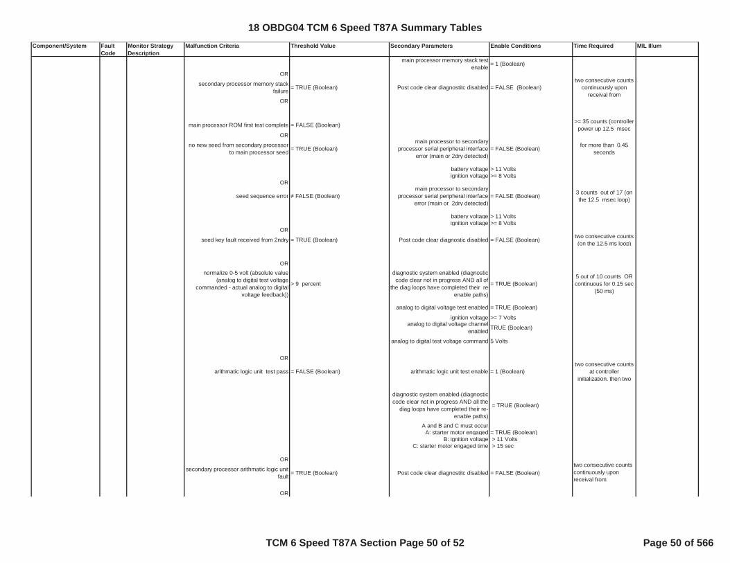
Component/System Fault Code
Monitor Strategy Description
Malfunction Criteria Threshold Value Secondary Parameters Enable Conditions Time Required MIL Illum
main processor memory stack test enable = 1 (Boolean)
OR
secondary processor memory stack failure = TRUE (Boolean) Post code clear diagnostitc disabled = FALSE (Boolean)
two consecutive counts continuously upon
receival from OR
main processor ROM first test complete = FALSE (Boolean) >= 35 counts (controller power up 12.5 msec
OR
no new seed from secondary processor to main processor seed = TRUE (Boolean)
main processor to secondary processor serial peripheral interface
error (main or 2dry detected)= FALSE (Boolean) for more than 0.45
seconds
battery voltage > 11 Voltsignition voltage >= 8 Volts
OR
seed sequence error FALSE (Boolean)main processor to secondary
processor serial peripheral interface error (main or 2dry detected)
= FALSE (Boolean) 3 counts out of 17 (on the 12.5 msec loop)
battery voltage > 11 Voltsignition voltage >= 8 Volts
OR
seed key fault received from 2ndry = TRUE (Boolean) Post code clear diagnostic disabled = FALSE (Boolean) two consecutive counts (on the 12.5 ms loop)
ORnormalize 0-5 volt (absolute value
(analog to digital test voltage commanded - actual analog to digital
voltage feedback))
> 9 percent
diagnostic system enabled (diagnostic code clear not in progress AND all of
the diag loops have completed their re-enable paths)
= TRUE (Boolean)5 out of 10 counts OR continuous for 0.15 sec
(50 ms)
analog to digital voltage test enabled = TRUE (Boolean)
ignition voltage >= 7 Voltsanalog to digital voltage channel
enabled TRUE (Boolean)
analog to digital test voltage command 5 Volts
OR
arithmatic logic unit test pass = FALSE (Boolean) arithmatic logic unit test enable = 1 (Boolean)two consecutive counts
at controller initialization, then two
diagnostic system enabled (diagnostic code clear not in progress AND all the
diag loops have completed their re-enable paths)
= TRUE (Boolean)
A and B and C must occurA: starter motor engaged = TRUE (Boolean)
B: ignition voltage > 11 VoltsC: starter motor engaged time > 15 sec
OR
secondary processor arithmatic logic unit fault = TRUE (Boolean) Post code clear diagnostitc disabled = FALSE (Boolean)
two consecutive counts continuously upon receival from
OR
18 OBDG04 TCM 6 Speed T87A Summary Tables
TCM 6 Speed T87A Section Page 50 of 52 Page 50 of 566

Component/System Fault Code
Monitor Strategy Description
Malfunction Criteria Threshold Value Secondary Parameters Enable Conditions Time Required MIL Illum
clock test fail = TRUE (Boolean) clock test enable = 1 (Boolean)two consecutive counts
at controller initialization, then two
diagnostic system enabled (diagnostic code clear not in progress AND all the
diag loops have completed their re-enable paths)
=TRUE (Boolean)
A and B and C must occurA: starter motor engaged = TRUE (Boolean)
B: ignition voltage > 11 VoltsC: starter motor engaged time > 15 sec
OR
configuration register test fail = TRUE (Boolean) configuration register test enable = 1 (Boolean) two consecutive counts
at controller initialization, then two
diagnostic system enabled (diagnostic code clear not in progress AND all the
diag loops have completed their re-enable paths)
= TRUE (Boolean)
A and B and C must occurA: starter motor engaged = TRUE (Boolean)
B: ignition voltage > 11 VoltsC: starter motor engaged time > 15 sec
OR
secondary processor configuration register fault = TRUE (Boolean)
Post code clear diagnostitc disabled= FALSE (Boolean)
two consecutive counts continuously upon
receival from
OR
main SOH discrete fault = TRUE (Boolean)Post code clear diagnostitc disabled
= FALSE (Boolean)two consecutive counts
continuously upon receival from
OR
SPI bus fault(i) = TRUE (Boolean)
diagnostic system enabled (diagnostic code clear not in progress AND all the
diag loops have completed their re-enable paths)
=TRUE (Boolean) 8 counts out of 16 (on the 6.25 msec loop)
A and B must occurA: run/crank voltage in range >= 11 Volts
ORbattery voltage in range > 11 VoltsB: Startup/Restart time >= 0.125 sec
Not Test Failed This Key On P062F
TCM Non-Volatile Memory read or write error (every controller intialization). = TRUE (Boolean)
every controller intialization
assembly calibration integrity (every controller initialization)
= TRUE (Boolean) every controller intialization
AControl Module Long Term Memory Performance
P062F Tests non volatile memory long term performance.
18 OBDG04 TCM 6 Speed T87A Summary Tables
TCM 6 Speed T87A Section Page 51 of 52 Page 51 of 566

Component/System Fault Code
Monitor Strategy Description
Malfunction Criteria Threshold Value Secondary Parameters Enable Conditions Time Required MIL Illum
NVM write error diagnotic enable TRUE
Control Module Serial Peripheral Interface Bus 2
P16E9Serial peripheral hardware fault detected by secondary processor.
secondary micro processor hardware serial peripheral device fault active = TRUE (Boolean)
secondary micro processor hardware serial peripheral device fault active
previous loop= TRUE (Boolean) Service mode $04 active and end of
trip pocessing active = FALSE(Boolean)
Control Module Serial Peripheral Interface Bus 1
P16F0 Secondary processor message error detected by main processor.
secondary micro processor serial peripheral device message valid
detected by primary micro processor since controller initialization
= FALSE (Boolean) fail count >= 39 counts (12.5 ms) cont
out of sample count >= 399 counts (12.5 ms) cont
ORsecondary micro processor serial peripheral device message valid
detected by primary micro processor after controller initialization
= FALSE (Boolean) fail count >= 39 counts (12.5 ms) cont
out of sample count >= 399 counts (12.5 OR
secondary micro processor serial peripheral device message valid
detected by primary micro processor after controller initialization
= FALSE(Boolean) fail count >= 159 counts (12.5 ms) NON continuous
out of sample count >= 399 counts (12.5 ms) NON continuous
NOT in low voltage engine crank condition defined by A or B below during, for low voltage mode timelow voltage mode time >= 0.025
secondsA) low voltage mode hysteresis time
<= 0.1 secondsB) ignition voltage, set low voltage
mode <= 6.4092 volts
A
A
18 OBDG04 TCM 6 Speed T87A Summary Tables
TCM 6 Speed T87A Section Page 52 of 52 Page 52 of 566

Component/System
FaultCode
Monitor StrategyDescription
Malfunction Criteria Threshold Value Secondary Parameters Enable Conditions Time Required MILIllum.
BackupTransmission RangeCommandMessageCounterIncorrect
C1201 This DTC monitors foran error incommunication with theBackup TransmissionRange CommandMessage Counter
Communication of theAlive Rolling Count orProtection Value from theBackup TransmissionRange CommandMessage Counter overLIN bus is incorrectfor
out of total samples
>= counts10.00
>= counts10.00
All the followingconditions are met for
Power Mode
Battery Voltage
>= milliseconds300.00
= Run
>= Volts11.00
Executes in250ms loop.
Type A,1 Trips
18 OBDG04 TCM 9 Speed T87A Summary Tables
TCM 9 Speed T87A Section Page 1 of 269 Page 53 of 566

Component/System
FaultCode
Monitor StrategyDescription
Malfunction Criteria Threshold Value Secondary Parameters Enable Conditions Time Required MILIllum.
BackupTransmission RangeCommandMessageCounterIncorrect
C1201 This DTC monitors foran error incommunication with theBackup TransmissionRange CommandMessage Counter
Communication of theAlive Rolling Count orProtection Value from theBackup TransmissionRange CommandMessage Counter overLIN bus is incorrectfor
out of total samples
>= counts10.00
>= counts10.00
All the followingconditions are met for
Power Mode
Battery Voltage
>= milliseconds300.00
= Run
>= Volts11.00
Executes in250ms loop.
Type A,1 Trips
18 OBDG04 TCM 9 Speed T87A Summary Tables
TCM 9 Speed T87A Section Page 2 of 269 Page 54 of 566
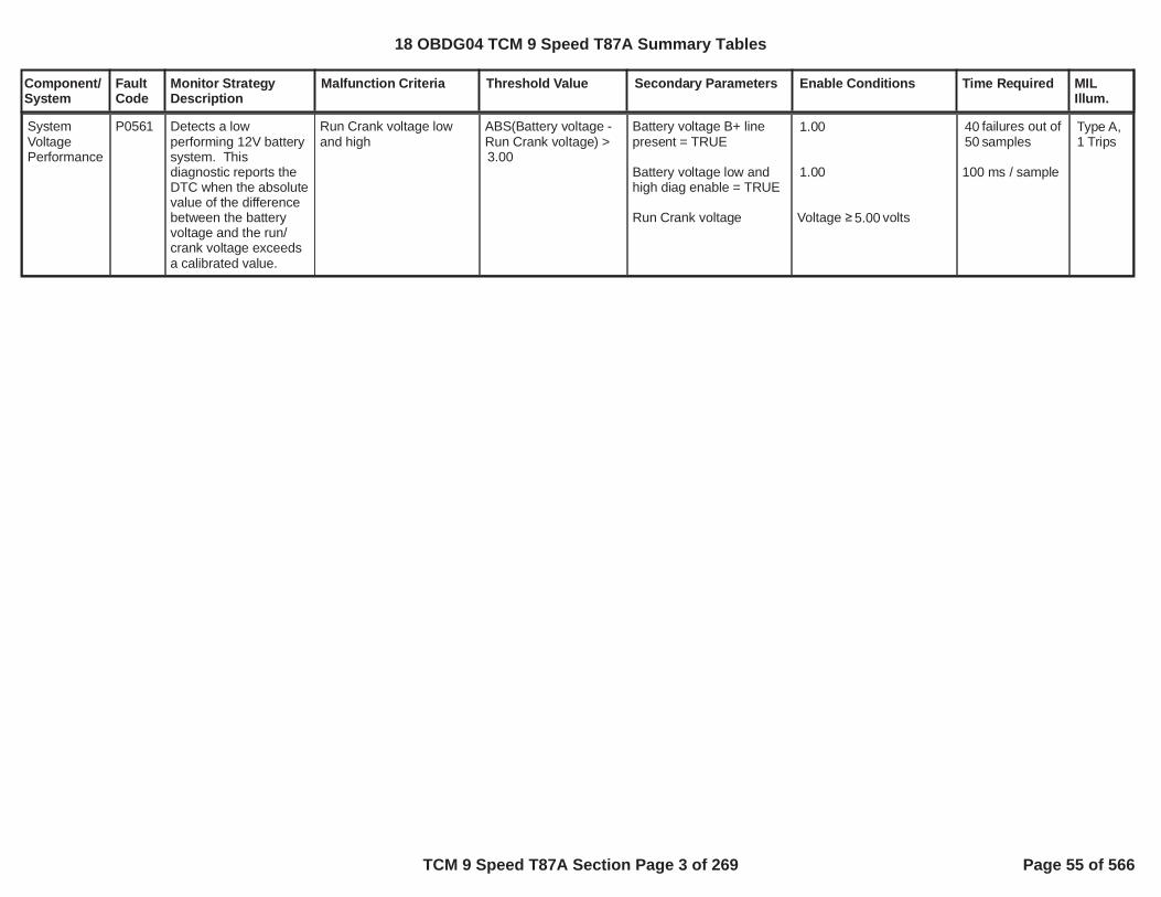
Component/System
FaultCode
Monitor StrategyDescription
Malfunction Criteria Threshold Value Secondary Parameters Enable Conditions Time Required MILIllum.
SystemVoltagePerformance
P0561 Detects a lowperforming 12V batterysystem. Thisdiagnostic reports theDTC when the absolutevalue of the differencebetween the batteryvoltage and the run/crank voltage exceedsa calibrated value.
Run Crank voltage lowand high
ABS(Battery voltage -Run Crank voltage) >3.00
Battery voltage B+ linepresent = TRUE
Battery voltage low andhigh diag enable = TRUE
Run Crank voltage
1.00
1.00
Voltage volts5.00
failures out of40samples50
100 ms / sample
Type A,1 Trips
18 OBDG04 TCM 9 Speed T87A Summary Tables
TCM 9 Speed T87A Section Page 3 of 269 Page 55 of 566

Component/System
FaultCode
Monitor StrategyDescription
Malfunction Criteria Threshold Value Secondary Parameters Enable Conditions Time Required MILIllum.
ETRSGMLANCommandSignalMessageIncorrect
P1775 This DTC monitors foran error incommunication with theETRS General StatusSignal
Communication of theAlive Rolling Count orProtection Value from theETRS GMLAN CommandSignal over CAN bus isincorrectfor
out of total samples
>= counts10
>= counts10.00
All the followingconditions are met for
Power Mode
Run/Crank IgnitionVoltage
>= milliseconds300.00
= Run
>= Volts11.00
Executes in250ms loop.
Type A,1 Trips
18 OBDG04 TCM 9 Speed T87A Summary Tables
TCM 9 Speed T87A Section Page 4 of 269 Page 56 of 566

Component/System
FaultCode
Monitor StrategyDescription
Malfunction Criteria Threshold Value Secondary Parameters Enable Conditions Time Required MILIllum.
ETRSGMLANCommandSignalMessageIncorrect
P1775 This DTC monitors foran error incommunication with theETRS General StatusSignal
Communication of theAlive Rolling Count orProtection Value from theETRS GMLAN CommandSignal over CAN bus isincorrectfor
out of total samples
>= counts10
>= counts10.00
All the followingconditions are met for
Power Mode
Run/Crank IgnitionVoltage
>= milliseconds300.00
= Run
>= Volts11.00
Executes in250ms loop.
Type A,1 Trips
18 OBDG04 TCM 9 Speed T87A Summary Tables
TCM 9 Speed T87A Section Page 5 of 269 Page 57 of 566

Component/System
FaultCode
Monitor StrategyDescription
Malfunction Criteria Threshold Value Secondary Parameters Enable Conditions Time Required MILIllum.
IgnitionSwitch Run/StartPositionCircuit Low
P2534 Detects a low ignitionswitch run/start positioncurcuit. This diagnosticreports the DTC whenthis circut is low.Monitoring occurswhen the ECM run/crank is active.
Ignition switch Run/Startposition circuit low
Run / Crank = FALSE Ignition switch Run/Startposition circuit low diagenable
and
Run / Crank active ECM
= 1.00
= TRUE
failures out280of samples280
25 ms / sample
Type A,1 Trips
18 OBDG04 TCM 9 Speed T87A Summary Tables
TCM 9 Speed T87A Section Page 6 of 269 Page 58 of 566

Component/System
FaultCode
Monitor StrategyDescription
Malfunction Criteria Threshold Value Secondary Parameters Enable Conditions Time Required MILIllum.
IgnitionSwitch Run/StartPositionCircuit High
P2535 Detects a high ignitionswitch run/start positioncurcuit. This diagnosticreports the DTC whenthis circut is high.Monitoring occurswhen the ECM run/crank is NOT active.
Ignition switch Run/Startposition circuit high
Run / Crank = TRUE Ignition switch Run/Startposition circuit low diagenable
and
Run / Crank active ECM
= 1.00
= FALSE
failures out280of samples280
25 ms / sample
Type A,1 Trips
18 OBDG04 TCM 9 Speed T87A Summary Tables
TCM 9 Speed T87A Section Page 7 of 269 Page 59 of 566

Component/System
FaultCode
Monitor StrategyDescription
Malfunction Criteria Threshold Value Secondary Parameters Enable Conditions Time Required MILIllum.
ControlModuleCommunication Bus A Off
U0073 This DTC monitors fora BUS A off condition
Bus off failures exceeds
before the sample time ofis reached
counts5(equivalent to 0.06seconds)
seconds0.81
General Enable Criteria:
U0073
Normal CAN transmissionon Bus A
Device Control
High Voltage VirtualNetwork Management
Ignition Voltage Criteria:
Run/Crank Ignitionvoltage
Power Mode
Off Cycle Enable Criteria:
KeCAND_b_OffKeyCycleDiagEnbl
Ignition Accessory LineandBattery Voltage
General Enable Criteriaand either Ignition VoltageCriteria or Off CycleEnable Criteria met for >
seconds5.0000
CAN hardware is busOFF for
Not Active on Current KeyCycle
Enabled
Not Active
Not Active
> Volts6.41
= run
= 1( 1 indicates enabled)
= Active
> Volts11.00
> seconds0.1625
Diagnostic runsin 12.5 ms loop
Type A,1 Trips
18 OBDG04 TCM 9 Speed T87A Summary Tables
TCM 9 Speed T87A Section Page 8 of 269 Page 60 of 566

Component/System
FaultCode
Monitor StrategyDescription
Malfunction Criteria Threshold Value Secondary Parameters Enable Conditions Time Required MILIllum.
LostCommunication WithECM
U0100 This DTC monitors fora loss ofcommunication with theengine control module
Message is not receivedfrom controller for
Message $0BE
Message $0C9
Message $18E
Message $1A1
Message $1A3
Message $1AA
Message $1BA
Message $287
Message $3D1
Message $3E9
Message $4C1
Message $4C7
Message $4D1
Message $4F1
Message $589
seconds0.50
seconds0.50
seconds0.50
seconds0.50
seconds12.00
seconds12.00
seconds12.00
seconds0.50
seconds12.00
seconds12.00
seconds12.00
seconds12.00
seconds12.00
seconds12.00
seconds12.00
General Enable Criteria:
U0073
Normal CAN transmissionon Bus A
Device Control
High Voltage VirtualNetwork Management
Ignition Voltage Criteria:
Run/Crank Ignitionvoltage
Power Mode
Off Cycle Enable Criteria:
KeCAND_b_OffKeyCycleDiagEnbl
Ignition Accessory LineandBattery Voltage
General Enable Criteriaand either Ignition VoltageCriteria or Off CycleEnable Criteria met for >
seconds5.0000
Power Mode is inaccessory or run or crankand High Voltage VirtualNetwork Management is
Not Active on Current KeyCycle
Enabled
Not Active
Not Active
> Volts6.41
= run
= 1(1 indicates enabled)
= Active
> Volts11.00
Diagnostic runsin 12.5 ms loop
Type A,1 Trips
18 OBDG04 TCM 9 Speed T87A Summary Tables
TCM 9 Speed T87A Section Page 9 of 269 Page 61 of 566

Component/System
FaultCode
Monitor StrategyDescription
Malfunction Criteria Threshold Value Secondary Parameters Enable Conditions Time Required MILIllum.
not active for
U0100
ECM
> seconds0.4000
Not Active on Current KeyCycle
is present on the bus
18 OBDG04 TCM 9 Speed T87A Summary Tables
TCM 9 Speed T87A Section Page 10 of 269 Page 62 of 566

Component/System
FaultCode
Monitor StrategyDescription
Malfunction Criteria Threshold Value Secondary Parameters Enable Conditions Time Required MILIllum.
LostCommunication WithECM
U0100 This DTC monitors fora loss ofcommunication with theengine control module
Message is not receivedfrom controller for
Message $0BE
Message $0C9
Message $18E
Message $1A1
Message $1A3
Message $1AA
Message $1BA
Message $287
Message $3D1
Message $3E9
Message $4C1
Message $4C7
Message $4D1
Message $4F1
Message $589
seconds0.50
seconds0.50
seconds0.50
seconds0.50
seconds12.00
seconds12.00
seconds12.00
seconds0.50
seconds12.00
seconds12.00
seconds12.00
seconds12.00
seconds12.00
seconds12.00
seconds12.00
General Enable Criteria:
U0073
Normal CAN transmissionon Bus A
Device Control
High Voltage VirtualNetwork Management
Ignition Voltage Criteria:
Run/Crank Ignitionvoltage
Power Mode
Off Cycle Enable Criteria:
KeCAND_b_OffKeyCycleDiagEnbl
Ignition Accessory LineandBattery Voltage
General Enable Criteriaand either Ignition VoltageCriteria or Off CycleEnable Criteria met for >
seconds5.0000
Power Mode is inaccessory or run or crankand High Voltage VirtualNetwork Management is
Not Active on Current KeyCycle
Enabled
Not Active
Not Active
> Volts6.41
= run
= 1(1 indicates enabled)
= Active
> Volts11.00
Diagnostic runsin 12.5 ms loop
Type A,1 Trips
18 OBDG04 TCM 9 Speed T87A Summary Tables
TCM 9 Speed T87A Section Page 11 of 269 Page 63 of 566

Component/System
FaultCode
Monitor StrategyDescription
Malfunction Criteria Threshold Value Secondary Parameters Enable Conditions Time Required MILIllum.
not active for
U0100
ECM
> seconds0.4000
Not Active on Current KeyCycle
is present on the bus
18 OBDG04 TCM 9 Speed T87A Summary Tables
TCM 9 Speed T87A Section Page 12 of 269 Page 64 of 566

Component/System
FaultCode
Monitor StrategyDescription
Malfunction Criteria Threshold Value Secondary Parameters Enable Conditions Time Required MILIllum.
LostCommunication WithChassisControlModule A
U012A This DTC monitors fora loss ofcommunication with theChassis ControlModule A.
Message is not receivedfrom controller for
Message $4DF
Message $1F7
seconds12.00
seconds0.50
General Enable Criteria:
U0073
Normal CAN transmissionon Bus A
Device Control
High Voltage VirtualNetwork Management
Ignition Voltage Criteria:
Run/Crank Ignitionvoltage
Power Mode
Off Cycle Enable Criteria:
KeCAND_b_OffKeyCycleDiagEnbl
Ignition Accessory Line
andBattery Voltage
General Enable Criteriaand either Ignition VoltageCriteria or Off CycleEnable Criteria met for >
seconds5.0000Power Mode is inaccessory or run or crankand High Voltage VirtualNetwork Management isnot active for
Not Active on Current KeyCycle
Enabled
Not Active
Not Active
> Volts6.41
= run
= 1(1 indicates enabled)
= Active
> Volts11.00
> seconds0.4000
Diagnostic runsin 12.5 ms loop
Type A,1 Trips
18 OBDG04 TCM 9 Speed T87A Summary Tables
TCM 9 Speed T87A Section Page 13 of 269 Page 65 of 566

Component/System
FaultCode
Monitor StrategyDescription
Malfunction Criteria Threshold Value Secondary Parameters Enable Conditions Time Required MILIllum.
U012A
CHCM A
Not Active on Current KeyCycle
is present on the bus
18 OBDG04 TCM 9 Speed T87A Summary Tables
TCM 9 Speed T87A Section Page 14 of 269 Page 66 of 566

Component/System
FaultCode
Monitor StrategyDescription
Malfunction Criteria Threshold Value Secondary Parameters Enable Conditions Time Required MILIllum.
LostCommunication WithChassisControlModule A
U012A This DTC monitors fora loss ofcommunication with theChassis ControlModule A.
Message is not receivedfrom controller for
Message $4DF
Message $1F7
seconds12.00
seconds0.50
General Enable Criteria:
U0073
Normal CAN transmissionon Bus A
Device Control
High Voltage VirtualNetwork Management
Ignition Voltage Criteria:
Run/Crank Ignitionvoltage
Power Mode
Off Cycle Enable Criteria:
KeCAND_b_OffKeyCycleDiagEnbl
Ignition Accessory Line
andBattery Voltage
General Enable Criteriaand either Ignition VoltageCriteria or Off CycleEnable Criteria met for >
seconds5.0000Power Mode is inaccessory or run or crankand High Voltage VirtualNetwork Management isnot active for
Not Active on Current KeyCycle
Enabled
Not Active
Not Active
> Volts6.41
= run
= 1(1 indicates enabled)
= Active
> Volts11.00
> seconds0.4000
Diagnostic runsin 12.5 ms loop
Type A,1 Trips
18 OBDG04 TCM 9 Speed T87A Summary Tables
TCM 9 Speed T87A Section Page 15 of 269 Page 67 of 566

Component/System
FaultCode
Monitor StrategyDescription
Malfunction Criteria Threshold Value Secondary Parameters Enable Conditions Time Required MILIllum.
U012A
CHCM A
Not Active on Current KeyCycle
is present on the bus
18 OBDG04 TCM 9 Speed T87A Summary Tables
TCM 9 Speed T87A Section Page 16 of 269 Page 68 of 566

Component/System
FaultCode
Monitor StrategyDescription
Malfunction Criteria Threshold Value Secondary Parameters Enable Conditions Time Required MILIllum.
LostCommunication WithHybridPowertrainControlModule
U0293 This DTC monitors fora loss ofcommunication with theHybrid PowertrainControl Module.
Message is not receivedfrom controller for
Message $1DF
Message $1A5
seconds12.0
seconds12.00
General Enable Criteria:
U0073
Normal CAN transmissionon Bus A
Device Control
High Voltage VirtualNetwork Management
Ignition Voltage Criteria:
Run/Crank Ignitionvoltage
Power Mode
Off Cycle Enable Criteria:
KeCAND_b_OffKeyCycleDiagEnbl
Ignition Accessory LineandBattery Voltage
General Enable Criteriaand either Ignition VoltageCriteria or Off CycleEnable Criteria met for >
seconds5.0000
Power Mode is inaccessory or run or crankand High Voltage VirtualNetwork Management is
Not Active on Current KeyCycle
Enabled
Not Active
Not Active
> Volts6.41
= run
= 1(1 indicates enabled)
= Active
> Volts11.00
Diagnostic runsin 12.5 ms loop
Type B,2 Trips
18 OBDG04 TCM 9 Speed T87A Summary Tables
TCM 9 Speed T87A Section Page 17 of 269 Page 69 of 566
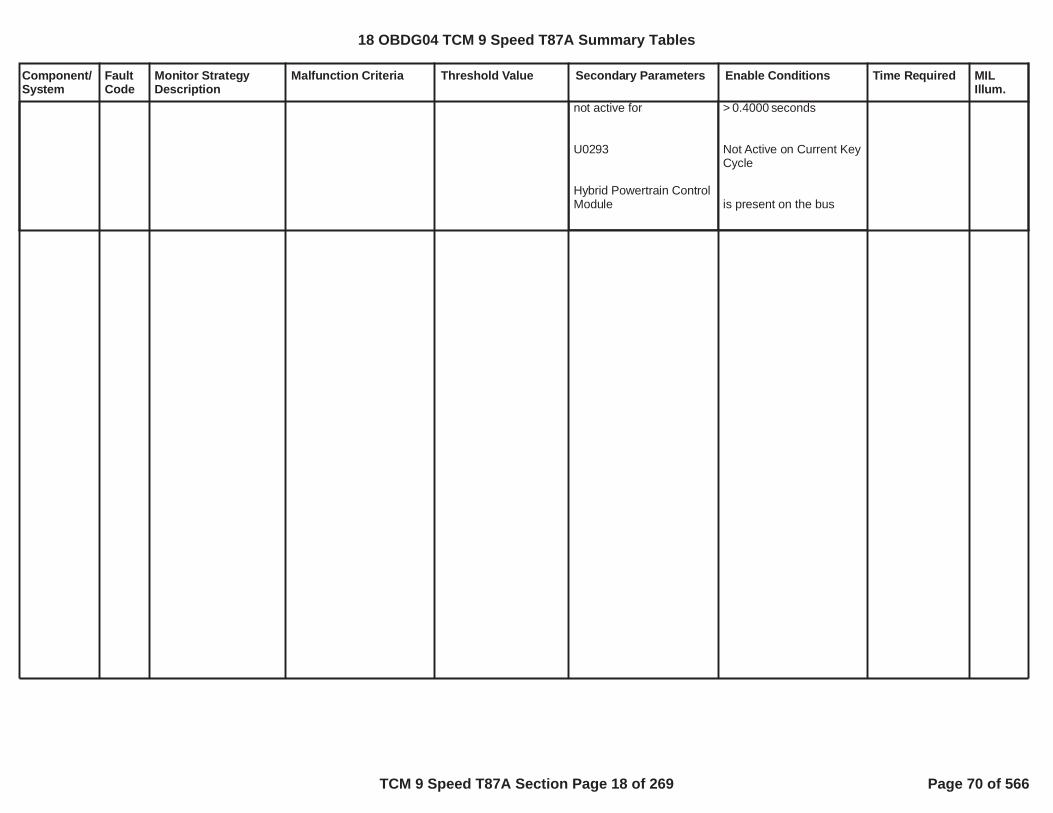
Component/System
FaultCode
Monitor StrategyDescription
Malfunction Criteria Threshold Value Secondary Parameters Enable Conditions Time Required MILIllum.
not active for
U0293
Hybrid Powertrain ControlModule
> seconds0.4000
Not Active on Current KeyCycle
is present on the bus
18 OBDG04 TCM 9 Speed T87A Summary Tables
TCM 9 Speed T87A Section Page 18 of 269 Page 70 of 566

Component/System
FaultCode
Monitor StrategyDescription
Malfunction Criteria Threshold Value Secondary Parameters Enable Conditions Time Required MILIllum.
LostCommunication WithHybridPowertrainControlModule
U0293 This DTC monitors fora loss ofcommunication with theHybrid PowertrainControl Module.
Message is not receivedfrom controller for
Message $1DF
Message $1A5
seconds12.0
seconds12.00
General Enable Criteria:
U0073
Normal CAN transmissionon Bus A
Device Control
High Voltage VirtualNetwork Management
Ignition Voltage Criteria:
Run/Crank Ignitionvoltage
Power Mode
Off Cycle Enable Criteria:
KeCAND_b_OffKeyCycleDiagEnbl
Ignition Accessory LineandBattery Voltage
General Enable Criteriaand either Ignition VoltageCriteria or Off CycleEnable Criteria met for >
seconds5.0000
Power Mode is inaccessory or run or crankand High Voltage VirtualNetwork Management is
Not Active on Current KeyCycle
Enabled
Not Active
Not Active
> Volts6.41
= run
= 1(1 indicates enabled)
= Active
> Volts11.00
Diagnostic runsin 12.5 ms loop
Type B,2 Trips
18 OBDG04 TCM 9 Speed T87A Summary Tables
TCM 9 Speed T87A Section Page 19 of 269 Page 71 of 566

Component/System
FaultCode
Monitor StrategyDescription
Malfunction Criteria Threshold Value Secondary Parameters Enable Conditions Time Required MILIllum.
not active for
U0293
Hybrid Powertrain ControlModule
> seconds0.4000
Not Active on Current KeyCycle
is present on the bus
18 OBDG04 TCM 9 Speed T87A Summary Tables
TCM 9 Speed T87A Section Page 20 of 269 Page 72 of 566

Component/System
FaultCode
Monitor StrategyDescription
Malfunction Criteria Threshold Value Secondary Parameters Enable Conditions Time Required MILIllum.
LateralAccelerationSensorCircuit Low
C124F Controller specificanalog circuitdiagnoses the rawlateral accelerationsignal for a short toground or open fault bycomparing raw signalvalue to fail thresholds.
raw lateral accelerationsignal when sensor typeis directly proportionalORraw lateral accelerationsignal when sensor typeis inversely proportional
update raw lateralacceleration signalstability time, fail andsample time,50 millisecond update rate
g-3.8500
g-3.8500
0.5 impedancebetween signal andcontroller ground)
battery voltagerun crank voltagediagnostic monitor enable
sensor type is eitherdirectly proportional orinversely proportional
U0073 fault activeU0073 test fail this key on
volts11.00volts11.00
= Boolean1
=CeLATR_e_VoltageDirectProp
= FALSE= FALSE
raw lateralaccelerationsignal stabilitytime 30.0seconds,fail time 75.0secondsout of sampletime 120.0seconds,50 millisecondupdate rate
SpecialType C
18 OBDG04 TCM 9 Speed T87A Summary Tables
TCM 9 Speed T87A Section Page 21 of 269 Page 73 of 566

Component/System
FaultCode
Monitor StrategyDescription
Malfunction Criteria Threshold Value Secondary Parameters Enable Conditions Time Required MILIllum.
LateralAccelerationSensorCircuit High
C1250 Controller specificanalog circuitdiagnoses the rawlateral accelerationsignal for a short topower or open fault bycomparing raw signalvalue to fail thresholds.
raw lateral accelerationsignal when sensor typeis directly proportionalORraw lateral accelerationsignal when sensor typeis inversely proportional
update raw lateralacceleration signalstability time, fail andsample time,50 millisecond update rate
g3.8500
g3.8500
0.5 impedancebetween signal andcontroller power)
battery voltagerun crank voltagediagnostic monitor enable
sensor type is eitherdirectly proportional orinversely proportional
U0073 fault activeU0073 test fail this key on
volts11.00volts11.00
= Boolean1
=CeLATR_e_VoltageDirectProp
= FALSE= FALSE
raw lateralaccelerationsignal stabilitytime 30.0seconds,fail time 75.0secondsout of sampletime 120.0seconds,50 millisecondupdate rate
SpecialType C
18 OBDG04 TCM 9 Speed T87A Summary Tables
TCM 9 Speed T87A Section Page 22 of 269 Page 74 of 566

Component/System
FaultCode
Monitor StrategyDescription
Malfunction Criteria Threshold Value Secondary Parameters Enable Conditions Time Required MILIllum.
LateralAccelerationSensorPerformance
C1251 Controller specificanalog circuitdiagnoses the rawlateral accelerationsignal for a signal valuethat is stuck in a validrange by comparingraw signal value to failthresholds.
ABS(raw lateralacceleration signal)ANDABS(raw lateralacceleration signal)
update raw lateralacceleration signal fail,50 millisecond update rate
g0.5300
g3.8500
battery voltagerun crank voltagediagnostic monitor enable
update raw lateralacceleration signal stablitytime:TOSS vehicle speedautomatic transmission isclutch to clutch OR dualclutchhigh side drive 1 enablehigh side drive 2 enablediagnsotic fault sequencegear activeP0716 fault activeP0716 test fail this key onP0717 fault activeP0717 test fail this key onP07BF fault activeP07BF test fail this key onP07C0 fault activeP07C0test fail this key onattained gearattained gear slip
ABS(raw lateralacceleration signal)update sample time
U0073 fault activeU0073 test fail this key onDTCs not fault active
volts11.00volts11.00
= Boolean1
KPH15.0= TRUE
= TRUE= TRUE= FALSE
= FALSE= FALSE= FALSE= FALSE= FALSE= FALSE= FALSE= FALSE= 1st thru 10th
RPM100.0
< g0.5300
= FALSE= FALSEVehicleSpeedSensor_FA
raw lateralaccelerationsignal stabilitytime 30.0seconds,fail time 75.0secondsout of sampletime 120.0seconds,50 millisecondupdate rate
SpecialType C
18 OBDG04 TCM 9 Speed T87A Summary Tables
TCM 9 Speed T87A Section Page 23 of 269 Page 75 of 566

Component/System
FaultCode
Monitor StrategyDescription
Malfunction Criteria Threshold Value Secondary Parameters Enable Conditions Time Required MILIllum.
LongitudinalAccelerationSensorCircuit Low
C1252 Controller specificanalog circuitdiagnoses the rawlongitudinalacceleration signal fora short to ground oropen fault bycomparing raw signalvalue to fail thresholds.
raw longitudinalacceleration signal whensensor type is directlyproportionalORraw longitudinalacceleration signal whensensor type is inverselyproportional
update raw longitudinalacceleration signalstability time, fail andsample time,50 millisecond update rate
g-3.8500
g-3.8500
0.5 impedancebetween signal andcontroller ground)
battery voltagerun crank voltagediagnostic monitor enable
sensor type is eitherdirectly proportional orinversely proportional
U0073 fault activeU0073 test fail this key on
volts11.00volts11.00
= Boolean1
=CeLATR_e_VoltageDirectProp
= FALSE= FALSE
raw longitudinalaccelerationsignal stabilitytime 30.0seconds,fail time 75.0secondsout of sampletime 120.0seconds,50 millisecondupdate rate
SpecialType C
18 OBDG04 TCM 9 Speed T87A Summary Tables
TCM 9 Speed T87A Section Page 24 of 269 Page 76 of 566

Component/System
FaultCode
Monitor StrategyDescription
Malfunction Criteria Threshold Value Secondary Parameters Enable Conditions Time Required MILIllum.
LongitudinalAccelerationSensorCircuit High
C1253 Controller specificanalog circuitdiagnoses the rawlongitudinalacceleration signal fora short to power oropen fault bycomparing raw signalvalue to fail thresholds.
raw longitudinalacceleration signal whensensor type is directlyproportionalORraw longitudinalacceleration signal whensensor type is inverselyproportional
update raw longitudinalacceleration signalstability time, fail andsample time,50 millisecond update rate
g3.8500
g3.8500
0.5 impedancebetween signal andcontroller power)
battery voltagerun crank voltagediagnostic monitor enable
sensor type is eitherdirectly proportional orinversely proportional
U0073 fault activeU0073 test fail this key on
volts11.00volts11.00
= Boolean1
=CeLATR_e_VoltageDirectProp
= FALSE= FALSE
raw longitudinalaccelerationsignal stabilitytime 30.0seconds,fail time 75.0secondsout of sampletime 120.0seconds,50 millisecondupdate rate
SpecialType C
18 OBDG04 TCM 9 Speed T87A Summary Tables
TCM 9 Speed T87A Section Page 25 of 269 Page 77 of 566

Component/System
FaultCode
Monitor StrategyDescription
Malfunction Criteria Threshold Value Secondary Parameters Enable Conditions Time Required MILIllum.
ABS(TOSS vehicle speedacceleration - rawlongitudinal accelerationsignal)
update raw longitudinalacceleration signal region1 fail time,50 millisecond update rate
g0.5300 battery voltagerun crank voltagediagnostic monitor enableregion 1 specific enable
update raw laterallongitudinal accelerationsignal stablity time:TOSS vehicle speedTOSS vehicle speedaccelerationautomatic transmission isclutch to clutch OR dualclutchhigh side drive 1 enablehigh side drive 2 enablediagnsotic fault sequencegear activeP0716 fault activeP0716 test fail this key onP0717 fault activeP0717 test fail this key onP07BF fault activeP07BF test fail this key onP07C0 fault activeP07C0test fail this key onattained gearattained gear slipABS(raw longitudinalacceleration signal)ANDABS(raw longitudinalacceleration signal)
update region 1 sampletime:brake pedal positionengine torqueTOSS vehicle speedaccelerationTOSS vehicle speedTOSS vehicle speed
volts11.00volts11.00
= Boolean1= Boolean0
KPH15.0g0.5300
= TRUE
= TRUE= TRUE= FALSE
= FALSE= FALSE= FALSE= FALSE= FALSE= FALSE= FALSE= FALSE= 1st thru 10th
RPM100.0g0.5300
g3.8500
%0.70Nm80.0
g0.1500
KPH15.0KPH200.0
raw laterallongitudinalaccelerationsignal stabilitytime 10.0seconds,fail time 75.0secondsout of sampletime 120.0seconds,50 millisecondupdate rate
region 1 fail timeseconds75.0
out of region 1sample time
seconds,120.050 millisecondupdate rate
LongitudinalAccelerationSensorPerformance
C1254 Controller specificanalog circuitdiagnoses the rawlongitudinalacceleration signalrationalized against theTOSS vehicle speedacceleration. Thediagnostic monitor canbe designed to detectan invalid longitudinalacceleration signalbased on the TOSSvehicle speed windowsand TOSS vehiclespeed acceleration, 4windows can beenabled. The deltabetween the TOSSvehicle speedacceleration andlongitudinalacceleration signal istaken within eachwindow to verify thedelta is small, no failureindicated, or the deltais large indicating thelongitudinalacceleration signal is inerror.
SpecialType C
18 OBDG04 TCM 9 Speed T87A Summary Tables
TCM 9 Speed T87A Section Page 26 of 269 Page 78 of 566

Component/System
FaultCode
Monitor StrategyDescription
Malfunction Criteria Threshold Value Secondary Parameters Enable Conditions Time Required MILIllum.
ABS(raw longitudinalacceleration signal)update sample time
U0073 fault activeU0073 test fail this key onDTCs not fault active
< g0.5300
= FALSE= FALSEVehicleSpeedSensor_FAVehicleSpeedSensorError
ABS(TOSS vehicle speedacceleration - rawlongitudinal accelerationsignal)
update raw longitudinalacceleration signal region2 fail time,50 millisecond update rate
g0.0000 battery voltagerun crank voltagediagnostic monitor enableregion 2 specific enable
update raw laterallongitudinal accelerationsignal stablity time:TOSS vehicle speedTOSS vehicle speedaccelerationautomatic transmission isclutch to clutch OR dualclutchhigh side drive 1 enablehigh side drive 2 enablediagnsotic fault sequencegear activeP0716 fault activeP0716 test fail this key onP0717 fault activeP0717 test fail this key onP07BF fault activeP07BF test fail this key onP07C0 fault activeP07C0test fail this key onattained gearattained gear slipABS(raw longitudinalacceleration signal)ANDABS(raw longitudinal
volts11.00volts11.00
= Boolean1= Boolean0
KPH15.0g0.5300
= TRUE
= TRUE= TRUE= FALSE
= FALSE= FALSE= FALSE= FALSE= FALSE= FALSE= FALSE= FALSE= 1st thru 10th
RPM100.0g0.5300
g3.8500
raw laterallongitudinalaccelerationsignal stabilitytime 10.0seconds,fail time 75.0secondsout of sampletime 120.0seconds,50 millisecondupdate rate
18 OBDG04 TCM 9 Speed T87A Summary Tables
TCM 9 Speed T87A Section Page 27 of 269 Page 79 of 566

Component/System
FaultCode
Monitor StrategyDescription
Malfunction Criteria Threshold Value Secondary Parameters Enable Conditions Time Required MILIllum.
acceleration signal)
update region 2 sampletime:brake pedal positionengine torqueTOSS vehicle speedaccelerationTOSS vehicle speedTOSS vehicle speed
ABS(raw longitudinalacceleration signal)update sample time
U0073 fault activeU0073 test fail this key onDTCs not fault active
%0.70Nm80.0
g0.1500
KPH0.0KPH0.0
< g0.5300
= FALSE= FALSEVehicleSpeedSensor_FAVehicleSpeedSensorError
region 2 fail timeseconds75.0
out of region 2sample time
seconds,120.050 millisecondupdate rate
ABS(TOSS vehicle speedacceleration - rawlongitudinal accelerationsignal)
update raw longitudinalacceleration signal region3 fail time,50 millisecond update rate
g0.0000 battery voltagerun crank voltagediagnostic monitor enableregion 3 specific enable
update raw laterallongitudinal accelerationsignal stablity time:TOSS vehicle speedTOSS vehicle speedaccelerationautomatic transmission isclutch to clutch OR dualclutchhigh side drive 1 enablehigh side drive 2 enablediagnsotic fault sequencegear activeP0716 fault activeP0716 test fail this key onP0717 fault activeP0717 test fail this key on
volts11.00volts11.00
= Boolean1= Boolean0
KPH15.0g0.5300
= TRUE
= TRUE= TRUE= FALSE
= FALSE= FALSE= FALSE= FALSE
raw laterallongitudinalaccelerationsignal stabilitytime 10.0seconds,fail time 75.0secondsout of sampletime 120.0seconds,50 millisecondupdate rate
18 OBDG04 TCM 9 Speed T87A Summary Tables
TCM 9 Speed T87A Section Page 28 of 269 Page 80 of 566

Component/System
FaultCode
Monitor StrategyDescription
Malfunction Criteria Threshold Value Secondary Parameters Enable Conditions Time Required MILIllum.
P07BF fault activeP07BF test fail this key onP07C0 fault activeP07C0test fail this key onattained gearattained gear slipABS(raw longitudinalacceleration signal)ANDABS(raw longitudinalacceleration signal)
update region 3 sampletime:brake pedal positionengine torqueABS(TOSS vehicle speedacceleration)TOSS vehicle speed
ABS(raw longitudinalacceleration signal)update sample time
U0073 fault activeU0073 test fail this key onDTCs not fault active
= FALSE= FALSE= FALSE= FALSE= 1st thru 10th
RPM100.0g0.5300
g3.8500
%0.70Nm80.0
g0.1000
KPH0.0
< g0.5300
= FALSE= FALSEVehicleSpeedSensor_FAVehicleSpeedSensorError
region 3 fail timeseconds75.0
out of region 3sample time
seconds,120.050 millisecondupdate rate
ABS(TOSS vehicle speedacceleration - rawlongitudinal accelerationsignal)
update raw longitudinalacceleration signal region4 fail time,50 millisecond update rate
g0.0000 battery voltagerun crank voltagediagnostic monitor enableregion 3 specific enable
update raw laterallongitudinal accelerationsignal stablity time:TOSS vehicle speedTOSS vehicle speedaccelerationautomatic transmission isclutch to clutch OR dual
volts11.00volts11.00
= Boolean1= Boolean0
KPH15.0g0.5300
= TRUE
raw laterallongitudinalaccelerationsignal stabilitytime 10.0seconds,fail time 75.0secondsout of sampletime 120.0seconds,50 millisecondupdate rate
18 OBDG04 TCM 9 Speed T87A Summary Tables
TCM 9 Speed T87A Section Page 29 of 269 Page 81 of 566

Component/System
FaultCode
Monitor StrategyDescription
Malfunction Criteria Threshold Value Secondary Parameters Enable Conditions Time Required MILIllum.
clutchhigh side drive 1 enablehigh side drive 2 enablediagnsotic fault sequencegear activeP0716 fault activeP0716 test fail this key onP0717 fault activeP0717 test fail this key onP07BF fault activeP07BF test fail this key onP07C0 fault activeP07C0test fail this key onattained gearattained gear slipABS(raw longitudinalacceleration signal)ANDABS(raw longitudinalacceleration signal)
update region 4 sampletime:brake pedal positionengine torqueTOSS vehicle speedaccelerationTOSS vehicle speedTOSS vehicle speed
ABS(raw longitudinalacceleration signal)update sample time
U0073 fault activeU0073 test fail this key onDTCs not fault active
= TRUE= TRUE= FALSE
= FALSE= FALSE= FALSE= FALSE= FALSE= FALSE= FALSE= FALSE= 1st thru 10th
RPM100.0g0.5300
g3.8500
%0.70Nm80.0
g0.1500
KPH0.0KPH0.0
< g0.5300
= FALSE= FALSEVehicleSpeedSensor_FAVehicleSpeedSensorError
region 4 fail timeseconds75.0
out of region 4sample time
seconds,120.050 millisecondupdate rate
18 OBDG04 TCM 9 Speed T87A Summary Tables
TCM 9 Speed T87A Section Page 30 of 269 Page 82 of 566

Component/System
FaultCode
Monitor StrategyDescription
Malfunction Criteria Threshold Value Secondary Parameters Enable Conditions Time Required MILIllum.
The Primary Processor'scalculated checksumdoes not match the storedchecksum value. Coversall software andcalibrations.
1 failure if the fault isdetected during thefirst pass.5.00failures if the faultoccurs after the firstpass is complete.
Diagnostic runscontinuously inthe background.
ControlModuleRead OnlyMemory(ROM)
P0601 This DTC will be storedif the calibration checksum is incorrect or theflash memory detectsan uncorrectable errorvia the Error CorrectingCode.
Type A,1 Trips
The Primary Processor'sError Correcting Codehardware in the flashmemory detects an error.Covers all software andcalibrations.
254failures detected viaError Correcting Code
Diagnostic runscontinuously viathe flashhardware.
The Primary Processor'scalculated checksumdoes not match the storedchecksum value for aselected subset of thecalibrations.
2 consecutive failuresdetected or5total failures detected.
Diagnostic runscontinuously.Will report adetected faultwithin 200 ms.
The SecondaryProcessor's calculatedchecksum does not matchthe stored checksumvalue. Covers allsoftware and calibrations.
1 failure if the fault isdetected during thefirst pass.
failures if the fault5occurs after the firstpass is complete.
Diagnostic runscontinuously inthe background.
In all cases, the failurecount is cleared whencontroller shuts down
18 OBDG04 TCM 9 Speed T87A Summary Tables
TCM 9 Speed T87A Section Page 31 of 269 Page 83 of 566

Component/System
FaultCode
Monitor StrategyDescription
Malfunction Criteria Threshold Value Secondary Parameters Enable Conditions Time Required MILIllum.
Static NVM region errordetected duringinitialization
Diagnostic runsat controllerpower up.
TCM LongTermMemoryReset
P0603 This DTC detects aninvalid NVM whichincludes a Static NVM,Perserved NVM, ECCROM in NVM FlashRegion, and PerservedNVM during shut down.
Type A,1 Trips
Perserved NVM regionerror detected duringinitialization
Diagnostic runsat controllerpower up.
ECC ROM fault detectedin NVM Flash region
ECC ROM Error Count > 3
Diagnostic runsat controllerpower up.
Perserved NVM regionerror detected during shutdown.
Diagnostic runsat controllerpower down.
18 OBDG04 TCM 9 Speed T87A Summary Tables
TCM 9 Speed T87A Section Page 32 of 269 Page 84 of 566

Component/System
FaultCode
Monitor StrategyDescription
Malfunction Criteria Threshold Value Secondary Parameters Enable Conditions Time Required MILIllum.
Indicates that the primaryprocessor is unable tocorrectly read data fromor write data to systemRAM. Detects data readdoes not match datawritten >=
counts254 Will finish firstmemory scanwithin 30seconds at allengineconditions -diagnostic runscontinuously(backgroundloop)
TCM RAMFailure
P0604 Indicates that the TCMhas detected a RAMfault. This includesPrimary ProcessorSystem RAM Fault,Primary ProcessorCache RAM Fault,Primary Processor TPURAM Fault, PrimaryProcessor Update DualStore RAM Fault,Primary ProcessorWrite Protected RAMFault, and SecondaryProcessor RAM Fault.This diagnostic runscontinuously.
Type A,1 Trips
Indicates that the primaryprocessor is unable tocorrectly read data fromor write data to cachedRAM. Detects data readdoes not match datawritten >=
counts3 Will finish firstmemory scanwithin 30seconds at allengineconditions -diagnostic runscontinuously(backgroundloop)
Indicates that the primaryprocessor is unable tocorrectly read data fromor write data to TPU RAM.Detects data read doesnot match data written >=
counts5 Will finish firstmemory scanwithin 30seconds at allengineconditions -diagnostic runscontinuously(backgroundloop)
Indicates that the primaryprocessor detects amismatch between thedata and dual data isfound during RAMupdates. Detects amismatch in data and dualdata updates >
s400.00 When dual storeupdates occur.
18 OBDG04 TCM 9 Speed T87A Summary Tables
TCM 9 Speed T87A Section Page 33 of 269 Page 85 of 566
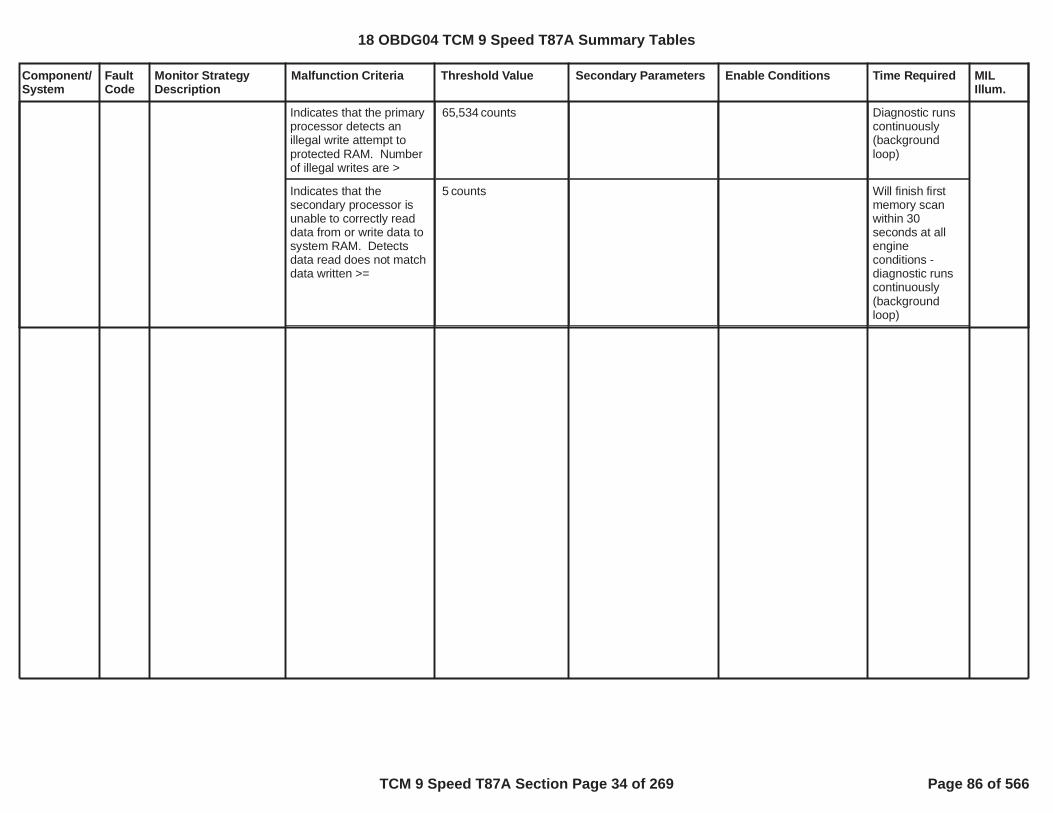
Component/System
FaultCode
Monitor StrategyDescription
Malfunction Criteria Threshold Value Secondary Parameters Enable Conditions Time Required MILIllum.
Indicates that the primaryprocessor detects anillegal write attempt toprotected RAM. Numberof illegal writes are >
counts65,534 Diagnostic runscontinuously(backgroundloop)
Indicates that thesecondary processor isunable to correctly readdata from or write data tosystem RAM. Detectsdata read does not matchdata written >=
counts5 Will finish firstmemory scanwithin 30seconds at allengineconditions -diagnostic runscontinuously(backgroundloop)
18 OBDG04 TCM 9 Speed T87A Summary Tables
TCM 9 Speed T87A Section Page 34 of 269 Page 86 of 566

Component/System
FaultCode
Monitor StrategyDescription
Malfunction Criteria Threshold Value Secondary Parameters Enable Conditions Time Required MILIllum.
Loss or invalid messageof SPI communicationfrom the SecondaryProcessor at initializationdetected by the PrimaryProcessor or loss orinvalid message of SPIcommunication from theSecondary Processorafter a valid message wasreceived by the PrimaryProcessor
Loss or invalidmessage atinitialization detectedor loss or invalidmessage after a validmessage was recieved
Run/Crank voltage >=8.00or Run/Crank voltage >=
,11.00else the failure will bereported for all conditions
In the primaryprocessor,
/ counts8 16intermittent or
counts10continuous;
counts100continuous @initialization.12.5 ms /count inthe TCM mainprocessor
Internal TCMProcessorIntegrityFault
P0606 Indicates that the TCMhas detected aninternal processorintegrity fault. Theseinclude diagnosticsdone on the SPICommunication as wellas a host of diagnosticsfor both the primaryand secondaryprocesssors.
Type A,1 Trips
Loss or invalid messageof SPI communicationfrom the PrimaryProcessor at initializationdetected by theSecondary Processor orloss or invalid message ofSPI communication fromthe Primary Processorafter a valid message wasreceived by theSecondary Processor
Loss or invalidmessage atinitialization detectedor loss or invalidmessage after a validmessage was recieved
In the secondaryprocessor,
/ counts64 161intermittent or
s0.1875continuous;
s0.4875continuous @initialization.12.5 ms /count inthe TCMsecondaryprocessor
Checks for stack over orunderflow in secondaryprocessor by looking forcorruption of knownpattern at stackboundaries. Checksnumber of stack over/under flow since lastpowerup reset >=
5 KeMEMD_b_StackLimitTestEnbl == 1Value ofKeMEMD_b_StackLimitTestEnbl is: .1(If 0, this test is disabled)
variable,depends onlength of time tocorrupt stack
MAIN processor is verifiedby responding to a seedsent from the secondarywith a key response tosecondary. Checksnumber of incorrect keys
2 incorrect seedswithin 8 messages,0.2000seconds
ignition in Run or Crank 150 ms for oneseed continuallyfailing
18 OBDG04 TCM 9 Speed T87A Summary Tables
TCM 9 Speed T87A Section Page 35 of 269 Page 87 of 566

Component/System
FaultCode
Monitor StrategyDescription
Malfunction Criteria Threshold Value Secondary Parameters Enable Conditions Time Required MILIllum.
received > or Secondaryprocessor has notreceived a new withintime limit
Time new seed notreceived exceeded
always running seconds0.450
MAIN processor receivesseed in wrong order
always running /3 17counts
intermittent. 50ms/count in theTCM mainprocessor
2 fails in a row in theSecondary processor'sALU check
KePISD_b_ALU_TestEnbld == 1Value ofKePISD_b_ALU_TestEnbld is: .1(If 0, this test is disabled)
25 ms
2 fails in a row in theSecondary processor'sconfiguration registermasks versus knowngood data
KePISD_b_ConfigRegTestEnbld == 1Value ofKePISD_b_ConfigRegTestEnbld is: .1(If 0, this test is disabled)
12.5 to 25 ms
Secondary processordetects an error in thetoggling of a hardwarediscrete line controlled bythe MAIN processor:number of discretechanges > =or < =over time window(50ms)
717
KePISD_b_MainCPU_SOH_FltEnbld == 1Value ofKePISD_b_MainCPU_SOH_FltEnbld is: 1.(If 0, this test is disabled)
time from initialization >=0.5000seconds
50 ms
Software background taskfirst pass time to completeexceeds
Run/Crank voltage >6.41
35.000seconds
18 OBDG04 TCM 9 Speed T87A Summary Tables
TCM 9 Speed T87A Section Page 36 of 269 Page 88 of 566

Component/System
FaultCode
Monitor StrategyDescription
Malfunction Criteria Threshold Value Secondary Parameters Enable Conditions Time Required MILIllum.
2 fails in a row in theMAIN processor's ALUcheck
KePISD_b_ALU_TestEnbld == 1Value ofKePISD_b_ALU_TestEnbld is: .1(If 0, this test is disabled)
25 ms
2 fails in a row in theMAIN processor'sconfiguration registermasks versus knowngood data
KePISD_b_ConfigRegTestEnbld == 1Value ofKePISD_b_ConfigRegTestEnbld is: .1(If 0, this test is disabled)
12.5 to 25 ms
Checks number of stackover/under flow since lastpowerup reset >=
5 KeMEMD_b_StackLimitTestEnbl == 1Value ofKeMEMD_b_StackLimitTestEnbl is: .1. (If 0, this test isdisabled)
variable,depends onlength of time tocorrupt stack
Voltage deviation > 9.00 KePISD_b_A2D_CnvrtrTestEnbld == 1Value ofKePISD_b_A2D_CnvrtrTestEnbld is: .1(If 0, this test is disabled)
/5 10counts or0.150seconds
continuous; 50ms/count in theTCM mainprocessor
Checks for ECC (errorcorrecting code) circuittest errors reported by thehardware for flashmemory. Incrementscounter during controllerinitialization if ECC erroroccured since lastcontroller initialization.Counter >=
(results in MIL),3(results in MIL and5
remedial action)
KeMEMD_b_FlashECC_CktTestEnbl == 1 Value ofKeMEMD_b_FlashECC_CktTestEnbl is: .1(If 0, this test is disabled)
variable,depends onlength of time toaccess flash withcorruptedmemory
Checks for ECC (error (results in MIL),3 KeMEMD_b_RAM_ECC_ variable,
18 OBDG04 TCM 9 Speed T87A Summary Tables
TCM 9 Speed T87A Section Page 37 of 269 Page 89 of 566

Component/System
FaultCode
Monitor StrategyDescription
Malfunction Criteria Threshold Value Secondary Parameters Enable Conditions Time Required MILIllum.
correcting code) circuittest errors reported by thehardware for RAMmemory circuit.Increments counter duringcontroller initialization ifECC error occured sincelast controller initialization.Counter >=
(results in MIL and5remedial action)
CktTestEnbl == 1Value ofKeMEMD_b_RAM_ECC_CktTestEnbl is: .1(If 0, this test is disabled)
depends onlength of time towrite flash toRAMvariable,depends onlength of time towrite flash toRAM
MAIN processor DMAtransfer from Flash toRAM has 1 failure
KePISD_b_DMA_XferTestEnbld == 1Value ofKePISD_b_DMA_XferTestEnbld is:
.1(If 0, this test is disabled)
variable,depends onlength of time towrite flash toRAM
Safety critical software isnot executed in properorder.
>= 1 incorrectsequence.
Table, f(Core, Loop Time).See supporting tables:P0606_ProgramSequence Watch Enablef(Core, Loop Time)(If 0, this Loop Time test isdisabled)
Fail Table, f(LoopTime). Seesupportingtables:P0606_PSWSequence Fail f(Loop Time)/
Sample Table, f(Loop Time)Seesupportingtables:P0606_PSWSequenceSample f(LoopTime)
counts
50 ms/count inthe TCM mainprocessor
18 OBDG04 TCM 9 Speed T87A Summary Tables
TCM 9 Speed T87A Section Page 38 of 269 Page 90 of 566

Component/System
FaultCode
Monitor StrategyDescription
Malfunction Criteria Threshold Value Secondary Parameters Enable Conditions Time Required MILIllum.
MAIN processordetermines a seed hasnot changed within aspecified time periodwithin the 50ms task.
Previous seed valueequals current seedvalue.
KePISD_b_SeedUpdKeyStorFltEnbl == 1Value ofKePISD_b_SeedUpdKeyStorFltEnbl is:
.1(If 0, this test is disabled)
Table, f(LoopTime). Seesupportingtables:P0606_LastSeed Timeout f(Loop Time)
18 OBDG04 TCM 9 Speed T87A Summary Tables
TCM 9 Speed T87A Section Page 39 of 269 Page 91 of 566

Component/System
FaultCode
Monitor StrategyDescription
Malfunction Criteria Threshold Value Secondary Parameters Enable Conditions Time Required MILIllum.
HWIO reports that writingto NVM (at shutdown) willnot succeed
Diagnostic runsat controllerpower up.
PowertrainInternalControlModuleEEPROMError
P062F This DTC detects aNVM long termperformance. There aretwo types ofdiagnostics that runduring controller powerup. One for HWIOreports that writing toNVM (at shutdown) willnot succeed, and theother HWIO reports theassembly calibrationintegrity check hasfailed.
Type A,1 Trips
HWIO reports theassembly calibrationintegrity check has failed
Diagnostic runsat controllerpower up.
18 OBDG04 TCM 9 Speed T87A Summary Tables
TCM 9 Speed T87A Section Page 40 of 269 Page 92 of 566

Component/System
FaultCode
Monitor StrategyDescription
Malfunction Criteria Threshold Value Secondary Parameters Enable Conditions Time Required MILIllum.
ActuatorSupplyVoltageCircuit Low
P0658 Controller specificoutput driver circuitdiagnoses the highsided driver circuit for ashort to ground failurewhen the output ispowered on bycomparing a voltagemeasurement tocontroller specificvoltage thresholds.
Voltage measurementoutside of controllerspecific acceptable rangeduring driver on stateindicates short to groundfailure.
Controller specific outputdriver circuit voltagethresholds are set to meetthe following controllerspecification for a short toground.
0.5 impedancebetween signal andcontroller ground
diagnostic monitor enablehigh side drive ONservice mode $04 notactiveservice fast learn notactiveP0658 fault activeP0658 test fail this key on
= Boolean1= TRUE
= FALSE= FALSE
fail count 6countsout of samplecount 2,400counts
6.25 millisecondupdate rate
Type A,1 Trips
18 OBDG04 TCM 9 Speed T87A Summary Tables
TCM 9 Speed T87A Section Page 41 of 269 Page 93 of 566

Component/System
FaultCode
Monitor StrategyDescription
Malfunction Criteria Threshold Value Secondary Parameters Enable Conditions Time Required MILIllum.
raw transmission fluidtemperature and thetransmission fluidtemperature warm up timehas elapsed
°C15.0
diagnsotic monitor enableP0712 NOT fault activeP0713 NOT fault activebattery voltage
run crank voltage
warm up test enableTFT rationality diagnosticmonitor enabled
driver accelerator pdealpositionengine torqueengine speedvehicle speedengine coolanttemperatureengine coolanttemperatureraw transmission fluidtemperatureraw transmission fluidtemperature
P2818 fault activeP2818 test fail this key on
DTCs not fault active
= Boolean1
volts9.00
volts9.00
= Boolean1=VeTFSR_b_TFT_RatlEnbl
%5.0
Nm50.0RPM500.0
KPH10.0°C-40.0
°C150.0
°C-40.0
°C150.0
= FALSE= FALSE
transmissionfluid temperaturewarm up time transmissionfluidtemperaturewarm up timeseconds
battery voltagetime 0.100seconds
run crank voltagetime 0.100seconds
Transmission FluidTemperature(TFT)SensorPerformance
P0711 The diagnostic monitorwill verify the time totransmission fluidtemperature warm upbased on the rawtransmissin fluidtemperature sesnor,any intermittent signalthat causes multipleunrealistic deltachanges (intermittentfaults) based on theraw transmissin fluidtemperature sesnor,and, raw transmissinfluid temperaturesesnor signal stuck invalid range.
Type B,2 Trips
18 OBDG04 TCM 9 Speed T87A Summary Tables
TCM 9 Speed T87A Section Page 42 of 269 Page 94 of 566

Component/System
FaultCode
Monitor StrategyDescription
Malfunction Criteria Threshold Value Secondary Parameters Enable Conditions Time Required MILIllum.
EngineTorqueEstInaccurateAcceleratorPedalFailureCrankSensor_FAECT_Sensor_FAVehicleSpeedSensor_FA
current transmission fluidtemperature string length= previous transmissionfluid temperaturetransmission temperaturestring length + (rawtransmission fluidtemperature - previousraw transmission fluidtemperature,update rate 100milliseconds,increment sample count
°C80.0
diagnsotic monitor enableP0712 NOT fault activeP0713 NOT fault activebattery voltage
run crank voltage
intermittent test enablepropulsion system active
= Boolean1
volts9.00
volts9.00
= Boolean1= TRUE
sample count counts10
evaluate failtemperaturethreshold, 100millisecondupdate rate, iftransmissionfluid temperaturestring lengthabove failthresholdincrement failtime
fail time 8.0seconds out ofsample time
seconds12.0
battery voltagetime 0.100seconds
run crank voltagetime 0.100seconds
raw transmission fluidtemperature - previous
°C0.0000 fail time 300.0seconds
18 OBDG04 TCM 9 Speed T87A Summary Tables
TCM 9 Speed T87A Section Page 43 of 269 Page 95 of 566

Component/System
FaultCode
Monitor StrategyDescription
Malfunction Criteria Threshold Value Secondary Parameters Enable Conditions Time Required MILIllum.
raw transmission fluidtemperature,update rate 100milliseconds,update fail time
diagnsotic monitor enableP0712 NOT fault activeP0713 NOT fault activebattery voltage
run crank voltage
stuck in range test enablepropulsion system activeraw transmission fluidtemperatureraw transmission fluidtemperature
= Boolean1
volts9.00
volts9.00
= Boolean1= TRUE
°C-40.0
°C150.0
battery voltagetime 0.100seconds
run crank voltagetime 0.100seconds
18 OBDG04 TCM 9 Speed T87A Summary Tables
TCM 9 Speed T87A Section Page 44 of 269 Page 96 of 566

Component/System
FaultCode
Monitor StrategyDescription
Malfunction Criteria Threshold Value Secondary Parameters Enable Conditions Time Required MILIllum.
Transmission FluidTemperatureSensorCircuit LowVoltage
P0712 Controller specificanalog circuitdiagnoses thetransmission fluidtemperature sensorand wiring for a short toground fault bycomparing a voltagemeasurement tocontroller specificvoltage thresholds,converted to aresistance value.
circuit resistanceupdate fail time1 seconds update rate
13.500
diagnostic monitor enable
battery voltage
run crank voltagerun crank voltage in rangetime
= Boolean1
volts9.00
volts9.00
fail time 5.00seconds out ofsample time
seconds6.001 secondsupdate rate
battery voltage inrange time
seconds0.100
run crank voltagein range time
seconds0.100
Type B,2 Trips
18 OBDG04 TCM 9 Speed T87A Summary Tables
TCM 9 Speed T87A Section Page 45 of 269 Page 97 of 566
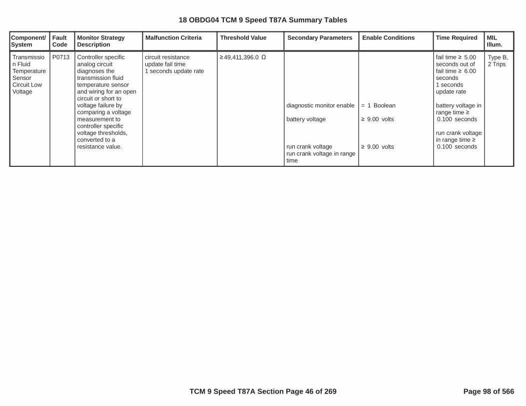
Component/System
FaultCode
Monitor StrategyDescription
Malfunction Criteria Threshold Value Secondary Parameters Enable Conditions Time Required MILIllum.
Transmission FluidTemperatureSensorCircuit LowVoltage
P0713 Controller specificanalog circuitdiagnoses thetransmission fluidtemperature sensorand wiring for an opencircuit or short tovoltage failure bycomparing a voltagemeasurement tocontroller specificvoltage thresholds,converted to aresistance value.
circuit resistanceupdate fail time1 seconds update rate
49,411,396.0
diagnostic monitor enable
battery voltage
run crank voltagerun crank voltage in rangetime
= Boolean1
volts9.00
volts9.00
fail time 5.00seconds out offail time 6.00seconds1 secondsupdate rate
battery voltage inrange time
seconds0.100
run crank voltagein range time
seconds0.100
Type B,2 Trips
18 OBDG04 TCM 9 Speed T87A Summary Tables
TCM 9 Speed T87A Section Page 46 of 269 Page 98 of 566

Component/System
FaultCode
Monitor StrategyDescription
Malfunction Criteria Threshold Value Secondary Parameters Enable Conditions Time Required MILIllum.
Input SpeedSensorPerformance
P0716 Detects unrealistic dropin raw transmissioninput speed signalRPM. Drop events arecounted up to failthreshold. A drop eventis defined by a suddendelta change in RPMfrom one value to alower value. The rawtransmission inputspeed must achieve avalue high enough torecord an unrealisticdrop sample to sample.Once the dropthreshold is met, failtime is accumualtedindicating the rawtransmission inputspeed has notrecovered above athreshold, allowing thefail event count toincrement. Multiple failevent counts mustoccur, but if the signalremains low, no furtherdeltas occur, the "InputSpeed Sensor CircuitLow Voltage" DTC willset before P0716, asP0716 is designed toset based on anintermittent rawtransmission inputspeed signal RPM.
delta raw transmissioninput speed
delta raw transmissioninput speed = rawtransmission input speed -last valid raw transmissioninput speed,25 millisecond update rate
RPM2,000.0 service mode $04 activediagnostic monitor enableP0717 test fail this key onP07BF test fail this key onP07C0 test fail this key on
last valid raw transmissioninput speedORvalid raw transmissioninput speed(before drop event)
last valid raw transmissioninput speed updates very25 milliseconds whenstablity time complete aslong as(delta delta rawtransmission input speedANDraw transmission inputspeed)
raw transmission outputspeedaccelerator pedal positionengine torqueengine torque
transmission hydraulicpressure available:engine speed
= FALSE= Boolean1= FALSE= FALSE= FALSE
RPM160.0
RPM160.0
RPM320.0
> RPM160.0
RPM254.0
%5.0Nm8,191.9
Nm30.0
RPM400.0
fail time 1.500secondsupdated failevent count,fail event count
counts,525 millisecondupdate rate
raw transmissioninput speed time
seconds2.000
stability time seconds0.100
engine speedtime
Type A,1 Trips
18 OBDG04 TCM 9 Speed T87A Summary Tables
TCM 9 Speed T87A Section Page 47 of 269 Page 99 of 566

Component/System
FaultCode
Monitor StrategyDescription
Malfunction Criteria Threshold Value Secondary Parameters Enable Conditions Time Required MILIllum.
DTCs not fault active AcceleratorPedalFailureEngineTorqueEstInaccurate
engine speedtime fortransmissionhydraulicpressureavailable
18 OBDG04 TCM 9 Speed T87A Summary Tables
TCM 9 Speed T87A Section Page 48 of 269 Page 100 of 566

Component/System
FaultCode
Monitor StrategyDescription
Malfunction Criteria Threshold Value Secondary Parameters Enable Conditions Time Required MILIllum.
Input SpeedSensorCircuit LowVoltage
P0717 Detects no activity inraw transmission inputspeed signal RPM dueto open ciruit electricalfailure mode or sensorinternal faults, or,controller internalfailure modes. The rawtransmission inputspeed signal RPM isrationalized againstvehicle conditions inwhich the thepowertrain is producingtorque available at thedrive wheels, but rawtransmission inputspeed signal RPMremains low. After asudden drop in rawtransmission inputspeed signal RPM, arace condition canoccur between P0717and "Input SpeedSensor Performance"depending on the truenature of the failure.
raw transmission inputspeedORTISS/TOSS fault (singlepower supply to TISS andTOSS) = TRUE,
update fail time25 millisecond update rate
RPM100.0
< RPM475.0
service mode $04 active
diagnostic monitor enablerun crank voltage
service fast learn activerun crank voltageP0722 fault activeP0723 fault activeP077C fault activeP077D fault activebrake pedal positionsesnor must be OBDII touse brake pedalconditionalbrake pedal positionsesnor typebrake pedal positionP0716 test fail this key onP07BF test fail this key onP07C0 test fail this key onaccelerator pedal positionengine torqueengine torque(transmission currentattained geartransmission currentattained gearraw transmission outputspeedORtransmission currentattained geartransmission currentattained gearraw transmission outputspeed)P0717 fault activeP0717 test fail this key on
= FALSE
= Boolean1volts5.00
= FALSEvolts9.00
= FALSE= FALSE= FALSE= FALSE
= CeBRKR_e_OBD
< %70.0= FALSE= FALSE= FALSE
%5.0Nm30.0
Nm8,191.9
CeCGSR_e_CR_Seventh
CeCGSR_e_CR_First
RPM162.0
CeCGSR_e_CR_Tenth
CeCGSR_e_CR_Seventh
fail time 4.00seconds
run crank voltagetime 25milliseconds
Type A,1 Trips
18 OBDG04 TCM 9 Speed T87A Summary Tables
TCM 9 Speed T87A Section Page 49 of 269 Page 101 of 566

Component/System
FaultCode
Monitor StrategyDescription
Malfunction Criteria Threshold Value Secondary Parameters Enable Conditions Time Required MILIllum.
TISS/TOSS fault (singlepower supply to TISS andTOSS) = TRUE occurswhen:(P0722 fail time high gearexceeds fail thresholdORP0722 fail time low gearexceeds fail threshold)TISS/TOSS has singlepower supply calibrationTISS/TOSS single powersupply test enabled
transmission hydraulicpressure available:engine speed
DTCs not fault active
RPM162.0
= FALSE= FALSE
= Boolean0
= Boolean1
RPM400.0
EngineTorqueEstInaccurate
engine speedtime engine speedtime fortransmissionhydraulicpressureavailable
18 OBDG04 TCM 9 Speed T87A Summary Tables
TCM 9 Speed T87A Section Page 50 of 269 Page 102 of 566

Component/System
FaultCode
Monitor StrategyDescription
Malfunction Criteria Threshold Value Secondary Parameters Enable Conditions Time Required MILIllum.
OutputSpeedSensorPerformance
P0721 The diagnostic monitordetermines if thedirection TOSS value iscoherent based on theon period time of thedirectional sensor andTOSS raw. When theon period timeindicates a transitionalstate, the directionmust also betransitional asmeasured by very slowTOSS raw RPM. Whenthe on period timeindicates a non-transitional state,forward or reverse, thedirection must also betransition, not forwardand not reverse.
TOSS raw directionwhen TOSS transitionalperiod = FALSEANDTOSS raw directionwhen TOSS transitionalperiod = FALSEORTOSS rawwhen TOSS transitionalperiod = TRUE
update fail and sampletime6.26 millisecond updaterate
FORWARD
REVERSE
RPM25.0
service mode $04 activediagnostic monitor enableTOSS count sampleperiodP0721 fault activeP0721 test fail this key on
TOSS transitional perioddetected = FALSE when:on periodon periodwhen direction unknownORon periodon periodwhen direction is reverseORon periodon periodwhen direction is forward
TOSS transitional perioddetected = TRUE when:on periodon periodwhen direction unknown
senor type is directionalsenor type cailbration
= FALSE= Boolean1 0 counts
= FALSE= FALSE
seconds0.3994seconds0.3193
< seconds0.2363> seconds0.1240
< seconds0.0811> seconds0.0088
< seconds0.3994> seconds0.3193
= CeTOSR_e_Directional
fail time 3.500secondsout of sampletime 5.000seconds
Type A,1 Trips
18 OBDG04 TCM 9 Speed T87A Summary Tables
TCM 9 Speed T87A Section Page 51 of 269 Page 103 of 566

Component/System
FaultCode
Monitor StrategyDescription
Malfunction Criteria Threshold Value Secondary Parameters Enable Conditions Time Required MILIllum.
OutputSpeedSensorCircuit LowVoltage
P0722 Detects no activity inraw transmissionoutput speed signalRPM due to open ciruitelectrical failure modeor sensor internalfaults, or, controllerinternal failure modes.The raw transmissionoutput speed signalRPM is rationalizedagainst vehicleconditions in which thethe powertrain isproducing torque, butraw transmissionoutput speed signalRPM remains low.After a sudden drop inraw transmissionoutput speed signalRPM, a race conditioncan occur betweenP0722 and "OutputSpeed Sensor CircuitIntermittent" dependingon the true nature ofthe failure.
raw transmission outputspeed,update fail time6.25 millisecond updaterate
when:attained gear
attained gear
ANDattained gear
use high gear fail timethresholdELSEuse low gear fail timethreshold
RPM30.0
CeCGSR_e_CR_First
CeCGSR_e_CR_Tenth
>CeCGSR_e_CR_Fourth
service mode $04 active
diagnostic monitor enable
when neutral rangeoccurs:(garage shiftORPRNDLORPRNDLORrange inhibit state)AND(engine torqueaccelerator pedalposition)
when not neutral rangeoccurs:attained gearattained gear(attained gear
engine torque hysteresishighengine torque hysteresislowaccelerator pedal positionhysteresis highaccelerator pedal positionhysteresis low)
when not neutral rangeoccurs:(attained gear
engine torque hysteresishighengine torque hysteresislow
= FALSE
= Boolean1
COMPLETE
= PARK
= NEUTRAL
no inhibt active
Nm8,192.0%100.0
CeCGSR_e_CR_First CeCGSR_e_CR_Tenth
>CeCGSR_e_CR_Fourth
Nm50.0
> Nm30.0
%5.0
> %3.0
CeCGSR_e_CR_FourthNm80.0
> Nm50.0
fail time 5.00seconds highgearORfail time 3.50seconds lowgear
Type A,1 Trips
18 OBDG04 TCM 9 Speed T87A Summary Tables
TCM 9 Speed T87A Section Page 52 of 269 Page 104 of 566
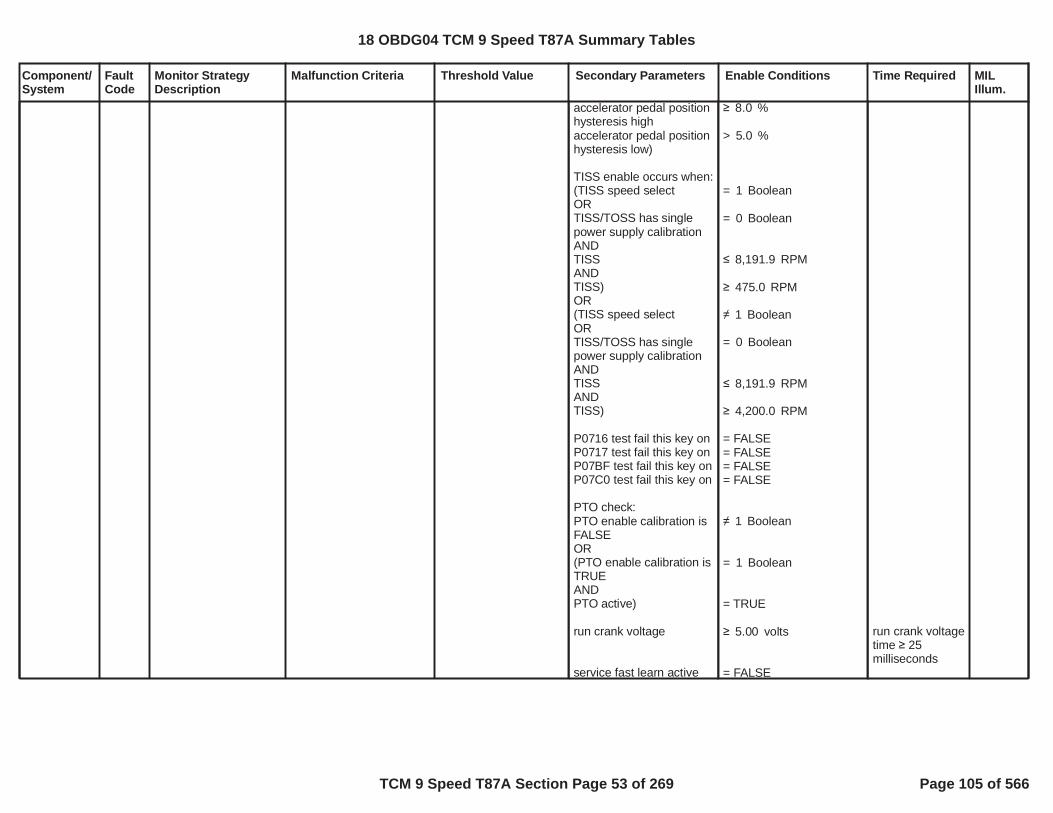
Component/System
FaultCode
Monitor StrategyDescription
Malfunction Criteria Threshold Value Secondary Parameters Enable Conditions Time Required MILIllum.
accelerator pedal positionhysteresis highaccelerator pedal positionhysteresis low)
TISS enable occurs when:(TISS speed selectORTISS/TOSS has singlepower supply calibrationANDTISSANDTISS)OR(TISS speed selectORTISS/TOSS has singlepower supply calibrationANDTISSANDTISS)
P0716 test fail this key onP0717 test fail this key onP07BF test fail this key onP07C0 test fail this key on
PTO check:PTO enable calibration isFALSEOR(PTO enable calibration isTRUEANDPTO active)
run crank voltage
service fast learn active
%8.0
> %5.0
= Boolean1
= Boolean0
RPM8,191.9
RPM475.0
Boolean1
= Boolean0
RPM8,191.9
RPM4,200.0
= FALSE= FALSE= FALSE= FALSE
Boolean1
= Boolean1
= TRUE
volts5.00
= FALSE
run crank voltagetime 25milliseconds
18 OBDG04 TCM 9 Speed T87A Summary Tables
TCM 9 Speed T87A Section Page 53 of 269 Page 105 of 566

Component/System
FaultCode
Monitor StrategyDescription
Malfunction Criteria Threshold Value Secondary Parameters Enable Conditions Time Required MILIllum.
run crank voltagetransmission fluidtemperatureP0723 test fail this key onP077C test fail this key onP077D test fail this key onP0722 fault activeP0722 test fail this key ontransmission hydraulicpressure available:engine speed
DTCs not fault active
volts9.00°C-40.00
= FALSE= FALSE= FALSE= FALSE= FALSE
RPM400.0
AcceleratorPedalFailureEngineTorqueEstInaccurate
engine speedtime engine speedtime fortransmissionhydraulicpressureavailable
18 OBDG04 TCM 9 Speed T87A Summary Tables
TCM 9 Speed T87A Section Page 54 of 269 Page 106 of 566

Component/System
FaultCode
Monitor StrategyDescription
Malfunction Criteria Threshold Value Secondary Parameters Enable Conditions Time Required MILIllum.
OutputSpeedSensorCircuitIntermittent
P0723 Detects unrealistic dropin raw transmissionoutput speed signalRPM. Drop events arecounted up to failthreshold. A drop eventis defined by a suddendelta change in RPMfrom one value to alower value. The rawtransmission outputspeed must achieve avalue high enough torecord an unrealisticdrop sample to sample.Once the dropthreshold is met, failtime is accumualtedindicating the rawtransmission outputspeed has notrecovered above athreshold, allowing thefail event count toincrement. Multiple failevent counts mustoccur, but if the signalremains low, no furtherdeltas occur, the"Output Speed SensorCircuit Low Voltage"DTC will set beforeP0723, as P0723 isdesigned to set basedon an intermittent rawtransmission outputspeed signal RPM.
4WD low fail threshold:delta raw transmissionoutput speedORNOT 4WD low failthreshold,update fail time,delta raw transmissionoutput speed = rawtransmission output speedprevious loop - rawtransmission outputspeed,25 millisecond update rate
RPM700.0
RPM700.0
service mode $04 activediagnostic monitor enable
transmission engagedstate
4WD low state
PTO check:PTO enable calibration isFALSEOR(PTO enable calibration isTRUEANDPTO active)
run crank voltage
service fast learn activerun crank voltageP077C test fail this key onP077D test fail this key on
when PRNDL is moved to
= FALSE= Boolean1
not engaged
= 4WD low state previousloop, 25 millisecondupdate rate
Boolean1
= Boolean1
= TRUE
volts5.00
= FALSEvolts9.00
= FALSE= FALSE
fail time 1.500secondsupdated failevent count,fail event count
counts,525 millisecondupdate rate
transmissionengaged statetime P0723transmissionengaged statetime threshold
4WD low changetime 3.0seconds
run crank voltagetime 25milliseconds
Type A,1 Trips
18 OBDG04 TCM 9 Speed T87A Summary Tables
TCM 9 Speed T87A Section Page 55 of 269 Page 107 of 566

Component/System
FaultCode
Monitor StrategyDescription
Malfunction Criteria Threshold Value Secondary Parameters Enable Conditions Time Required MILIllum.
NEUTRAL allowtransmission engagedstate time before enablingfail evaluation, or, if rawraw transmission outputspeed is active inNEUTRAL enable failevaluation:PRNDLOR
PRNDLOR
PRNDLOR
raw transmission outputspeedORlast valid raw transmissionoutput speed
determine if rawtransmission input speedis stable:(raw transmission inputspeed - raw transmissioninput speed previous, 25millisecond updateANDraw transmission inputspeed)OR(TISS/TOSS has singlepower supply calibrationANDraw transmission inputspeed)
=CeTRGR_e_PRNDL_Neutral=CeTRGR_e_PRNDL_Transitional1N-D transitional=CeTRGR_e_PRNDL_Transitional4R-N transitional
RPM250.0
RPM250.0
RPM4,095.9
RPM160.0
= Boolean0
= 0.0 RPM
raw transmissioninput speedstability time
seconds2.00
no time required
18 OBDG04 TCM 9 Speed T87A Summary Tables
TCM 9 Speed T87A Section Page 56 of 269 Page 108 of 566

Component/System
FaultCode
Monitor StrategyDescription
Malfunction Criteria Threshold Value Secondary Parameters Enable Conditions Time Required MILIllum.
select delta RPM failtheshold:(4WD low stateAND $WD low valid)select P0723 4WD TOSSdelta fail thresholdotherwise use P0723TOSS delta fail threshold
last valid raw transmissionoutput speedORvalid raw transmissionoutput speed(before drop event)
last valid raw transmissionoutput speed updatesvery 25 milliseconds whenstablity time complete aslong as(delta delta rawtransmission output speedANDraw transmission outputspeed)
transmission hydraulicpressure available:engine speed
DTCs not fault active
= TRUE= TRUE
> RPM89.0
> RPM89.0
RPM140.0
RPM89.0
RPM400.0
AcceleratorPedalFailureEngineTorqueEstInaccurate
raw transmissionoutput speedtime 2.00seconds
stability time seconds0.100
engine speedtime engine speedtime fortransmissionhydraulicpressureavailable
18 OBDG04 TCM 9 Speed T87A Summary Tables
TCM 9 Speed T87A Section Page 57 of 269 Page 109 of 566

Component/System
FaultCode
Monitor StrategyDescription
Malfunction Criteria Threshold Value Secondary Parameters Enable Conditions Time Required MILIllum.
TorqueConverterClutch (TCC)SystemPerformance- GF9specific
P0741 The GF9 diagnosticmonitor detects thetransmission torqueconverter control valvefailed hydraulically on.The torque converterhydraulic control circuitis multiplexed with thetransmission clutchselect valve hydrauliccontrol circuit, allowingfor the torque convertercontrol valve stuck ontest to execute whenthe clutch select valvesolenoid is commandedON. When the clutchselect valve solenoid iscommanded ON as thevehicle speeddecreases toward zeroKPH, and, if the torqueconverter control valveis stuck on, the torqueconverter slip speedrate of change will havea large slope whiledecreasing toward zeroRPM, and the torqueconverter slip speedwill remain low nearzero RPM.
while control valve testtime timing down:rate of change of torqueconvert slip speed = (ABS(current loop value torqueconvert slip speed -previous loop valuetorque convert slipspeed) / 25 milliseconds)when clutch select valvesoleniod multiplexed toTCC hydraulicANDtorque convert slip speed= ABS(engine speed -transmission input shaftspeed)THENincrement fail time25 millisecond update rate
P0741 (GF9 specific)torque convertderivative slip speedfail thresholdsee supporting tables
P0741 (GF9 specific)TCC slip speed crashRPM
diagnostic monitor enable(TCC stuck off enableORTCC stuck on enable)hydraulic pressureavailable:engine speed
service fast learn activebattery voltage
run crank voltage
P281B falut activeP281D falut activeP281E falut active
PRNDLPRNDLPRNDLtransmission fluidtemperature
= Boolean1= Boolean1
= Boolean1
RPM400.0
= FALSEvolts9.00
volts9.00
= FALSE= FALSE= FALSE
PARK NEUTRAL REVERSE
°C-6.66
failt ime 0.250seconds,increment failcountfail count 4counts25 millisecondupdate rate
engine speedtime engine speedtime fortransmissionhydraulicpressureavailablesee supportingtable
battery voltagetime 0.100secondsrun crank voltagetime 0.100seconds
Type A,1 Trips
18 OBDG04 TCM 9 Speed T87A Summary Tables
TCM 9 Speed T87A Section Page 58 of 269 Page 110 of 566

Component/System
FaultCode
Monitor StrategyDescription
Malfunction Criteria Threshold Value Secondary Parameters Enable Conditions Time Required MILIllum.
transmission fluidtemperatureaccelerator pedal positionaccelerator pedal positionvehicle speedvehicle speedTCC command modebreak latch state (clutchselect valve solenoidcontrol)P0722 fault pendingP0723 fault pendingP0716 fault pendingP0717 fault pendingP07BF fault pendingP07C0 fault pending(PTO active ORPTO disable calibration)transmission fluidtemperaturetransmission fluidtemperatureengine torqueengine torqueP0741 test fail this key onvehicle speedengine speedengine speedaccelerator pedal position4WD low state(driver shift mode activeORdriver shift modecalibration)(misfire requests TCC offORmisfire TCC offcalibration)(clucth control solenoidstuck on OR solenoidstuck OFF intrusive shiftactive)
°C130.00
%0.00%1.00
KPH3.0KPH9.5
= OFF disabled (clutch select
valve transitioning)
= FALSE= FALSE= FALSE= FALSE= FALSE= FALSE= FALSE= Boolean1
°C-6.66
°C130.00
Nm55.0Nm800.0
= FALSEKPH45.0RPM400.0
RPM5,500.0%95.0
= FALSE= FALSE
= Boolean0
= Boolean0
= FALSE
18 OBDG04 TCM 9 Speed T87A Summary Tables
TCM 9 Speed T87A Section Page 59 of 269 Page 111 of 566
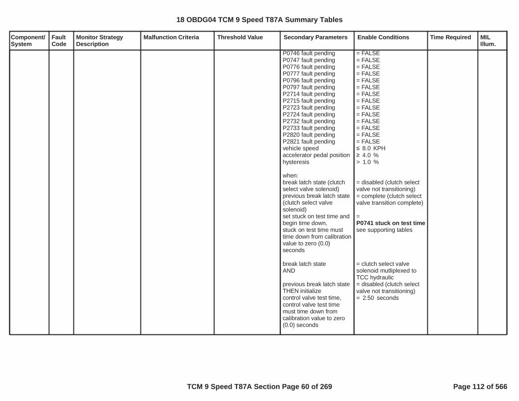
Component/System
FaultCode
Monitor StrategyDescription
Malfunction Criteria Threshold Value Secondary Parameters Enable Conditions Time Required MILIllum.
P0746 fault pendingP0747 fault pendingP0776 fault pendingP0777 fault pendingP0796 fault pendingP0797 fault pendingP2714 fault pendingP2715 fault pendingP2723 fault pendingP2724 fault pendingP2732 fault pendingP2733 fault pendingP2820 fault pendingP2821 fault pendingvehicle speedaccelerator pedal positionhysteresis
when:break latch state (clutchselect valve solenoid)previous break latch state(clutch select valvesolenoid)set stuck on test time andbegin time down,stuck on test time musttime down from calibrationvalue to zero (0.0)seconds
break latch stateAND
previous break latch stateTHEN initializecontrol valve test time,control valve test timemust time down fromcalibration value to zero(0.0) seconds
= FALSE= FALSE= FALSE= FALSE= FALSE= FALSE= FALSE= FALSE= FALSE= FALSE= FALSE= FALSE= FALSE= FALSE
KPH8.0%4.0
> %1.0
= disabled (clutch selectvalve not transitioning)= complete (clutch selectvalve transition complete)
=P0741 stuck on test timesee supporting tables
= clutch select valvesolenoid mutliplexed toTCC hydraulic= disabled (clutch selectvalve not transitioning)= seconds2.50
18 OBDG04 TCM 9 Speed T87A Summary Tables
TCM 9 Speed T87A Section Page 60 of 269 Page 112 of 566

Component/System
FaultCode
Monitor StrategyDescription
Malfunction Criteria Threshold Value Secondary Parameters Enable Conditions Time Required MILIllum.
DTCs not fault active AcceleratorPedalFailureEngineTorqueEstInaccurateP0716, P0717, P07BF,P07C0P0722, P0723, P077C,P077D
18 OBDG04 TCM 9 Speed T87A Summary Tables
TCM 9 Speed T87A Section Page 61 of 269 Page 113 of 566

Component/System
FaultCode
Monitor StrategyDescription
Malfunction Criteria Threshold Value Secondary Parameters Enable Conditions Time Required MILIllum.
PressureControl (PC)Solenoid AStuck Off
P0746 Each pressure controlsolenoid stuck offdiagnostic monitordetects a clutchpressure controlsolenoid failedhydraulically off, whilethe solenoid iselectrically functional.In the failure mode theclutch slip speed, andgear box gear slip, willbe excessive, not nearor at zero RPM. Theclutch slip speed iscalculated based onthe transmission levernode design, requiringtransmission input shaftspeed, transmissionoutput shaft speed,and, one transmissionintermediate shaftspeed. The clutchpressure controlsolenoid is tested afteran automatictransmission shiftoccurs and has beenconsidered shiftcomplete, or, steadystate gear is deemedactive, range shiftcomplete. When theautomatic transmissionshift is complete,steady state gear isconsidered, the clutchpressure controlsolenoid is mapped totransmission line
C1 clutch slip speed,update fail time6.25 milliscond update
RPM200.0
use battery voltagecalibration is FALSEOR(use battery voltagecalibration is TRUEANDbattery voltage
use run crank voltagecalibration is FALSEOR(use run crank voltagecalibration is TRUEANDrun crank voltage
TCM output driver highside driver 1, clutchpressure control solenoiddriver circuit enabled
TCM output driver highside driver 2, clutchpressure control solenoiddriver circuit enabled
service fast learn activeservice solenoid cleaningprocedure active
hydraulic pressure
= Boolean1
= Boolean1
volts9.00
= Boolean0
= Boolean0
volts9.00
= TRUE Boolean
= TRUE Boolean
= FALSE Boolean= FALSE Boolean
fail time 3.00seconds,update fail count,fail count 3counts6.25 milliscondupdate
battery voltagetime 0.100seconds
run crank voltagetime 0.100seconds
Type A,1 Trips
18 OBDG04 TCM 9 Speed T87A Summary Tables
TCM 9 Speed T87A Section Page 62 of 269 Page 114 of 566

Component/System
FaultCode
Monitor StrategyDescription
Malfunction Criteria Threshold Value Secondary Parameters Enable Conditions Time Required MILIllum.
pressure control, whichnormally allows theclutch to maintain fulltorque holding capacityat the given enginecrankshaft torque, tomaintain true gearratio. When the clutchpressure controlsolenoid is failedhydraulically off, theclutch does notmaintain holdingcapacity at any enginecrankshaft torque, andthe clutch slip speed isuncontrollable. Theclutch pressure controlsolenoid test issuspended if the higherlevel safety startlemitigation function isactive. The safetystartle mitigationfunction is triggeredwhen a sudden vehicledeceleration occursdue to a clutchpressure controlsolenoid that has failedin the opposite sense,clutch pressure controlsolenoid failedhydraulically on, whilethe solenoid iselectrically functional,which must take priorityover any clutchpressure controlsolenoid stuck offdiagnostic monitor. Allclutch pressure control
available:engine speed
enable C1 clutch slipspeed fail compare when:diagnostic clutch test C1((startle mitigation activeOR(startle mitigation activeANDstartle mitigation gear))(see startle mitigationactive NOTE below)unintended decelerationfault pending ORunintended decelerationfault pending enableFASLE(startle mitigation)clutch steady stateadaptive activetransmission output shaftspeedC1 clutch slip speed valid,all speed sesnors arefunctional for lever nodeclucth slip speedcalculation
accelerator pedal positionengine speed
diagnostic clutch test C1set to HOLDING CLUTCHwhen:clutch solenoid test state
RPM400.0
= HOLDING CLUTCH= FALSE
= TRUE
initial startle mitigationgear
= FALSE
= Boolean0
= FALSE
RPM89.0
= TRUE
%2.00RPM1,500.0
= NEUTRAL TEST
engine speedtime engine speedtime fortransmissionhydraulicpressureavailablesee supportingtable
18 OBDG04 TCM 9 Speed T87A Summary Tables
TCM 9 Speed T87A Section Page 63 of 269 Page 115 of 566

Component/System
FaultCode
Monitor StrategyDescription
Malfunction Criteria Threshold Value Secondary Parameters Enable Conditions Time Required MILIllum.
solenoid stuck on/offdiagnostic monitors areemission MIL DTCs.System voltage mustbe normal, all clutchpressure controlsolenoid driver circuitsmust be functional, noclutch pressure controlsolenoid electrical orperformance faults canbe present, and nospeed sensor electricalor performance faultscan be present, or thea clutch pressurecontrol solenoid stuckoff test is disabled. Thisdiagnostic monitor isrelative to the GF9 C1CB123456, or, GR10C1 CB123456R, clutchpressure controlsolenoid.
((startle mitigation activeOR(startle mitigation activeANDstartle mitigation gear))(see startle mitigationactive NOTE below)C1 clutch pressured map
clutch solenoid test stateset to NEUTRAL TESTwhen:test triggerinitialize range shiftcomplete time,whenrange shift state,range shift complete timemust time down to zerowhenrange shift complete
test trigger set to TRUE:enable forward gear ANDdirection requestORenable reverse gear ANDdirection requestcurrent loop test triggerclutch control solenoidtest staterange shift state
NOTE: startle mitigationactive is used to detectunintended decelerationdue to clutch pressurecontrol solenoid stuck on
= FALSE
= TRUE
initial startle mitigationgear
= mapped to linepressure, C1 clutchpressure has transtionedfrom off-applying-applied
= TRUE
range shift completed
= Boolean1= forward gear
= Boolean0= reverse gear= FALSE NEUTRAL TEST
= range shift completed
initialize rangeshift completetime = 1.000seconds,range shiftcomplete timemust time downto zerowhenrange shiftcomplete
18 OBDG04 TCM 9 Speed T87A Summary Tables
TCM 9 Speed T87A Section Page 64 of 269 Page 116 of 566

Component/System
FaultCode
Monitor StrategyDescription
Malfunction Criteria Threshold Value Secondary Parameters Enable Conditions Time Required MILIllum.
failure modes, the clutchpressure control solenoidstuck on DTCs beingP0747 P0777 P0797P2715 P2724 P2733P2821
DTCs not fault pending
DTCs not test fail this keyon
DTCs not fault active
P0716 P0717 P0722P0723 P077C P077DP07BF P07C0
P0707 P0708 P0746P0747 P0776 P0777P0796 P0797 P2714P2715 P2723 P2724P2732 P2733 P2820P2821
AcceleratorPedalFailureCrankSensor_FAP0707 P0708 P0716P0717 P07BF P07C0P0722 P0723 P077CP077D P172A P172BP176B P176C P176DP17C5 P17CC P17CDP17CE P17D3 P17D6P2805
18 OBDG04 TCM 9 Speed T87A Summary Tables
TCM 9 Speed T87A Section Page 65 of 269 Page 117 of 566
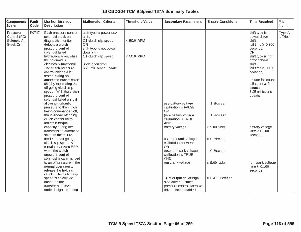
Component/System
FaultCode
Monitor StrategyDescription
Malfunction Criteria Threshold Value Secondary Parameters Enable Conditions Time Required MILIllum.
PressureControl (PC)Solenoid AStuck On
P0747 Each pressure controlsolenoid stuck ondiagnostic monitordetects a clutchpressure controlsolenoid failedhydraulically on, whilethe solenoid iselectrically functional.The clutch pressurecontrol solenoid istested during anautomatic transmissionshift by monitoring theoff going clutch slipspeed. With the clutchpressure controlsolenoid failed on, stillallowing hydraulicpressure to the clutchbeing commanded off,the intended off goingclutch continues tomaintain torquecapacity during thetransmission automaticshift. In the failuremode, the off goingclutch slip speed willremain near zero RPMwhen the clutchpressure controlsolenoid is commandedto an off pressure in thenormal operation torelease the holdingclutch. The clutch slipspeed is calculatedbased on thetransmission levernode design, requiring
shift type is power downshift,C1 clutch slip speedORshift type is not powerdown shift,C1 clutch slip speed
update fail time6.25 milliscond update
< RPM50.0
< RPM50.0
use battery voltagecalibration is FALSEOR(use battery voltagecalibration is TRUEANDbattery voltage
use run crank voltagecalibration is FALSEOR(use run crank voltagecalibration is TRUEANDrun crank voltage
TCM output driver highside driver 1, clutchpressure control solenoiddriver circuit enabled
= Boolean1
= Boolean1
volts9.00
= Boolean0
= Boolean0
volts9.00
= TRUE Boolean
shift type ispower downshift,fail time 0.800seconds,ORshift type is notpower downshift,fail time 0.150seconds,
update fail count,fail count 3counts6.25 milliscondupdate
battery voltagetime 0.100seconds
run crank voltagetime 0.100seconds
Type A,1 Trips
18 OBDG04 TCM 9 Speed T87A Summary Tables
TCM 9 Speed T87A Section Page 66 of 269 Page 118 of 566
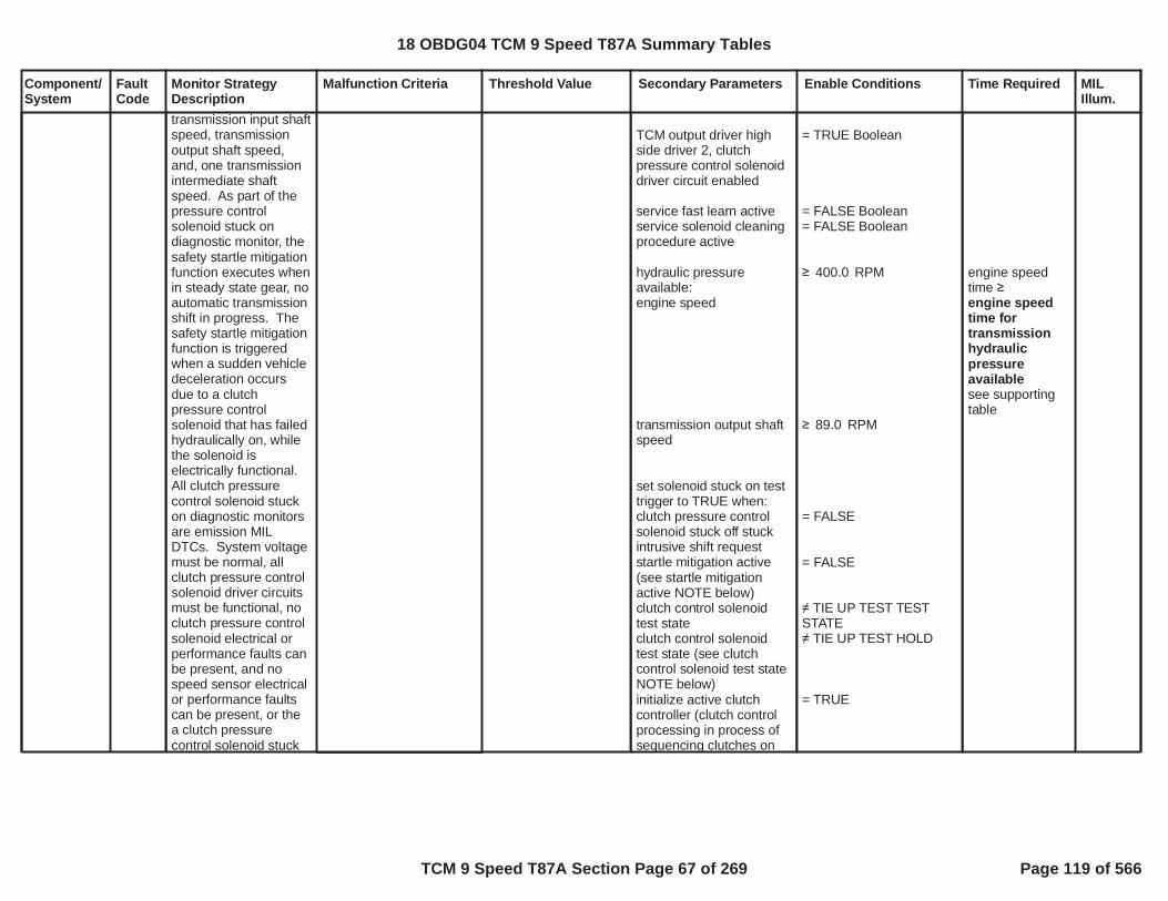
Component/System
FaultCode
Monitor StrategyDescription
Malfunction Criteria Threshold Value Secondary Parameters Enable Conditions Time Required MILIllum.
transmission input shaftspeed, transmissionoutput shaft speed,and, one transmissionintermediate shaftspeed. As part of thepressure controlsolenoid stuck ondiagnostic monitor, thesafety startle mitigationfunction executes whenin steady state gear, noautomatic transmissionshift in progress. Thesafety startle mitigationfunction is triggeredwhen a sudden vehicledeceleration occursdue to a clutchpressure controlsolenoid that has failedhydraulically on, whilethe solenoid iselectrically functional.All clutch pressurecontrol solenoid stuckon diagnostic monitorsare emission MILDTCs. System voltagemust be normal, allclutch pressure controlsolenoid driver circuitsmust be functional, noclutch pressure controlsolenoid electrical orperformance faults canbe present, and nospeed sensor electricalor performance faultscan be present, or thea clutch pressurecontrol solenoid stuck
TCM output driver highside driver 2, clutchpressure control solenoiddriver circuit enabled
service fast learn activeservice solenoid cleaningprocedure active
hydraulic pressureavailable:engine speed
transmission output shaftspeed
set solenoid stuck on testtrigger to TRUE when:clutch pressure controlsolenoid stuck off stuckintrusive shift requeststartle mitigation active(see startle mitigationactive NOTE below)clutch control solenoidtest stateclutch control solenoidtest state (see clutchcontrol solenoid test stateNOTE below)initialize active clutchcontroller (clutch controlprocessing in process ofsequencing clutches on
= TRUE Boolean
= FALSE Boolean= FALSE Boolean
RPM400.0
RPM89.0
= FALSE
= FALSE
TIE UP TEST TESTSTATE TIE UP TEST HOLD
= TRUE
engine speedtime engine speedtime fortransmissionhydraulicpressureavailablesee supportingtable
18 OBDG04 TCM 9 Speed T87A Summary Tables
TCM 9 Speed T87A Section Page 67 of 269 Page 119 of 566
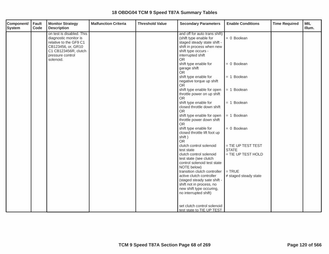
Component/System
FaultCode
Monitor StrategyDescription
Malfunction Criteria Threshold Value Secondary Parameters Enable Conditions Time Required MILIllum.
on test is disabled. Thisdiagnostic monitor isrelative to the GF9 C1CB123456, or, GR10C1 CB123456R, clutchpressure controlsolenoid.
and off for auto trans shift)(shift type enable forstaged steady state shift -shift in process when newshift type occurs -interrupted shiftORshift type enable forgarage shiftORshift type enable fornegative torque up shiftORshift type enable for openthrottle power on up shiftORshift type enable forclosed throttle down shiftORshift type enable for openthrottle power down shiftORshift type enable forclosed throttle lift foot upshift )ORclutch control solenoidtest stateclutch control solenoidtest state (see clutchcontrol solenoid test stateNOTE below)transition clutch controlleractive clutch controller(staged steady sate shift -shift not in process, nonew shift type occuring,no interrupted shift)
set clutch control solenoidtest state to TIE UP TEST
= Boolean0
= Boolean0
= Boolean1
= Boolean1
= Boolean1
= Boolean1
= Boolean0
= TIE UP TEST TESTSTATE= TIE UP TEST HOLD
= TRUE staged steady state
18 OBDG04 TCM 9 Speed T87A Summary Tables
TCM 9 Speed T87A Section Page 68 of 269 Page 120 of 566

Component/System
FaultCode
Monitor StrategyDescription
Malfunction Criteria Threshold Value Secondary Parameters Enable Conditions Time Required MILIllum.
TEST STATE when:solenoid stuck on testtriggercurrent loop clutch controlsolenoid test stateORcurrent loop clutch controlsolenoid test state (seeclutch control solenoidtest state NOTE below)range shift statesolenoid stuck on testtriggeradditional off going clutchoccured
(clutch control solenoidtest state ORclutch control solenoidtest state) (see clutchcontrol solenoid test stateNOTE below)diagnostic clutch test
(C1 off going clutchpressure control ramptime out complete ANDoff going clutch pressureramp control ramp timeout enable)ORC1 off going clutchpressure
= TRUE
= TEST WAITING
= TIE UP TEST HOLD
range shift complete= TRUE
= TRUE
= TIE UP TEST TESTSTATE= TIE UP TEST HOLD
= OFF GOING CLUTCHTEST= TRUE
= Boolean1
kPa350.0 for C1 off goingclutch pressuretime P0747 C1 clutchexhaust delaytime closedthrottle lift footup shiftOR
18 OBDG04 TCM 9 Speed T87A Summary Tables
TCM 9 Speed T87A Section Page 69 of 269 Page 121 of 566

Component/System
FaultCode
Monitor StrategyDescription
Malfunction Criteria Threshold Value Secondary Parameters Enable Conditions Time Required MILIllum.
engine torqueprimary on coming clutchactiveprimary on coming controlstateclosed throttle lift foot upshift primary on comingclutch pressureORopen throttle power on upshift primary on comingclutch pressureORgarage shift primary on
Nm8,191.8= TRUE
clutch fill phase
kPa690.0
kPA2,100.0
kPa750.0
P0747 C1 clutchexhaust delaytime openthrottle poweron up shiftORP0747 C1 clutchexhaust delaytime garageshiftORP0747 C1 clutchexhaust delaytime closedthrottle downshiftORP0747 C1 clutchexhaust delaytime negativetorque up shiftORP0747 C1 clutchexhaust delaytime openthrottle powerdown shiftsee supportingtables
18 OBDG04 TCM 9 Speed T87A Summary Tables
TCM 9 Speed T87A Section Page 70 of 269 Page 122 of 566

Component/System
FaultCode
Monitor StrategyDescription
Malfunction Criteria Threshold Value Secondary Parameters Enable Conditions Time Required MILIllum.
coming clutch pressureORnegative torque up shiftprimary on coming clutchpressureORopen throttle power downshift primary on comingclutch pressureORclosed throttle down shiftprimary on coming clutchpressureC1 clutch slip speed valid,all speed sesnors arefunctional for lever nodeclucth slip speedcalculation
NOTE: Clutch controlsolenoid test state TIE UPTEST HOLD is necessary,as it is possible to havemultiple off going clutchesduring one automatictransmission shift. Clutchcontrol solenoid test stateis set to TIE UP TESTHOLD during anautomatic transmissionshift due to twoconditions:Current value of clutchcontrol solenoid test stateis TIE UP TEST TESTSTATE, when one offgoing clutch pressurecontrol solenoid stuck ondiagnostic monitor iscurrently executing.AND
kPa690.0
kPa400.0
kPa690.0
= TRUE
18 OBDG04 TCM 9 Speed T87A Summary Tables
TCM 9 Speed T87A Section Page 71 of 269 Page 123 of 566

Component/System
FaultCode
Monitor StrategyDescription
Malfunction Criteria Threshold Value Secondary Parameters Enable Conditions Time Required MILIllum.
That off going clutchpressure control solenoidstuck on diagnosticmonitor currentlyexecuting passes, thecorresponding clutch slipspeed clutch slip speedfail threshold.Once clutch controlsolenoid test state is setto TIE UP TEST HOLD, itremains TIE UP TESTHOLD during theautomatic transmissionshift, until:An additional off goingclutch occurs, asindicated by solenoidstuck on test trigger =TRUE, subsequentlyclutch control solenoidtest state is reset to TIEUP TEST TEST STATE, toallow the additionalcorresponding off goingclutch pressure controlsolenoid stuck ondiagnostic monitor toexecute.ORThe automatictransmission shiftcompletes, range shiftstate = range shiftcomplete.
NOTE: Startle mitigationis used to detectunintended vehicledeceleration due to aclutch pressure control
18 OBDG04 TCM 9 Speed T87A Summary Tables
TCM 9 Speed T87A Section Page 72 of 269 Page 124 of 566

Component/System
FaultCode
Monitor StrategyDescription
Malfunction Criteria Threshold Value Secondary Parameters Enable Conditions Time Required MILIllum.
solenoid stuck on failuremode that occurs duringsteady state gear, notduring an automatictransmission shift. Thestartle mitigation activethen forces thetransmission clutchpressure control systemto a safe gear or neutralstate, based on the activeand inactive clutches,when the unintendedvehicle decelerationoccurred. Once a safevehicle gear state isattained, the gear andclutch pressure controlsystem allows transitionsof the clutches on and off,to sequence automatictransmission shifts, singlestep shifts. As eachsingle step automatictransmission shift occursthe normal pressurecontrol solenoid stuck ondiagnostic monitorsexecute to verify whichclutch pressure controlsolenoid is in the stuck onfailure mode, allowing oneof the clutch pressurecontrol solenoid stuck onDTCs to set P0747,P0777, P0797, P2715,P2724, P2733, P2821.
DTCs not fault pending P0716 P0717 P0722P0723 P077C P077DP07BF P07C0
18 OBDG04 TCM 9 Speed T87A Summary Tables
TCM 9 Speed T87A Section Page 73 of 269 Page 125 of 566

Component/System
FaultCode
Monitor StrategyDescription
Malfunction Criteria Threshold Value Secondary Parameters Enable Conditions Time Required MILIllum.
DTCs not test fail this keyon
DTCs not fault active
P0707 P0708 P0746P0747 P0776 P0777P0796 P0797 P2714P2715 P2723 P2724P2732 P2733 P2820P2821
AcceleratorPedalFailureCrankSensor_FAP0707 P0708 P0716P0717 P07BF P07C0P0722 P0723 P077CP077D P172A P172BP176B P176C P176DP17C5 P17CC P17CDP17CE P17D3 P17D6P2805
18 OBDG04 TCM 9 Speed T87A Summary Tables
TCM 9 Speed T87A Section Page 74 of 269 Page 126 of 566

Component/System
FaultCode
Monitor StrategyDescription
Malfunction Criteria Threshold Value Secondary Parameters Enable Conditions Time Required MILIllum.
PressureControl (PC)Solenoid BStuck Off
P0776 Each pressure controlsolenoid stuck offdiagnostic monitordetects a clutchpressure controlsolenoid failedhydraulically off, whilethe solenoid iselectrically functional.In the failure mode theclutch slip speed, andgear box gear slip, willbe excessive, not nearor at zero RPM. Theclutch slip speed iscalculated based onthe transmission levernode design, requiringtransmission input shaftspeed, transmissionoutput shaft speed,and, one transmissionintermediate shaftspeed. The clutchpressure controlsolenoid is tested afteran automatictransmission shiftoccurs and has beenconsidered shiftcomplete, or, steadystate gear is deemedactive, range shiftcomplete. When theautomatic transmissionshift is complete,steady state gear isconsidered, the clutchpressure controlsolenoid is mapped totransmission line
C1 clutch slip speed,update fail time6.25 milliscond update
RPM200.0
use battery voltagecalibration is FALSEOR(use battery voltagecalibration is TRUEANDbattery voltage
use run crank voltagecalibration is FALSEOR(use run crank voltagecalibration is TRUEANDrun crank voltage
TCM output driver highside driver 1, clutchpressure control solenoiddriver circuit enabled
TCM output driver highside driver 2, clutchpressure control solenoiddriver circuit enabled
service fast learn activeservice solenoid cleaningprocedure active
hydraulic pressure
= Boolean1
= Boolean1
volts9.00
= Boolean0
= Boolean0
volts9.00
= TRUE Boolean
= TRUE Boolean
= FALSE Boolean= FALSE Boolean
fail time 3.00seconds,update fail count,fail count 3counts6.25 milliscondupdate
battery voltagetime 0.100seconds
run crank voltagetime 0.100seconds
Type A,1 Trips
18 OBDG04 TCM 9 Speed T87A Summary Tables
TCM 9 Speed T87A Section Page 75 of 269 Page 127 of 566

Component/System
FaultCode
Monitor StrategyDescription
Malfunction Criteria Threshold Value Secondary Parameters Enable Conditions Time Required MILIllum.
pressure control, whichnormally allows theclutch to maintain fulltorque holding capacityat the given enginecrankshaft torque, tomaintain true gearratio. When the clutchpressure controlsolenoid is failedhydraulically off, theclutch does notmaintain holdingcapacity at any enginecrankshaft torque, andthe clutch slip speed isuncontrollable. Theclutch pressure controlsolenoid test issuspended if the higherlevel safety startlemitigation function isactive. The safetystartle mitigationfunction is triggeredwhen a sudden vehicledeceleration occursdue to a clutchpressure controlsolenoid that has failedin the opposite sense,clutch pressure controlsolenoid failedhydraulically on, whilethe solenoid iselectrically functional,which must take priorityover any clutchpressure controlsolenoid stuck offdiagnostic monitor. Allclutch pressure control
available:engine speed
enable C2 clutch slipspeed fail compare when:diagnostic clutch test C2((startle mitigation activeOR(startle mitigation activeANDstartle mitigation gear))(see startle mitigationactive NOTE below)unintended decelerationfault pending ORunintended decelerationfault pending enableFASLE(startle mitigation)clutch steady stateadaptive activetransmission output shaftspeedC2 clutch slip speed valid,all speed sesnors arefunctional for lever nodeclucth slip speedcalculation
accelerator pedal positionengine speed
diagnostic clutch test C2set to HOLDING CLUTCHwhen:clutch solenoid test state
RPM400.0
= HOLDING CLUTCH= FALSE
= TRUE
initial startle mitigationgear
= FALSE
= Boolean0
= FALSE
RPM89.0
= TRUE
%2.00RPM1,500.0
= NEUTRAL TEST
engine speedtime engine speedtime fortransmissionhydraulicpressureavailablesee supportingtable
18 OBDG04 TCM 9 Speed T87A Summary Tables
TCM 9 Speed T87A Section Page 76 of 269 Page 128 of 566

Component/System
FaultCode
Monitor StrategyDescription
Malfunction Criteria Threshold Value Secondary Parameters Enable Conditions Time Required MILIllum.
solenoid stuck on/offdiagnostic monitors areemission MIL DTCs.System voltage mustbe normal, all clutchpressure controlsolenoid driver circuitsmust be functional, noclutch pressure controlsolenoid electrical orperformance faults canbe present, and nospeed sensor electricalor performance faultscan be present, or thea clutch pressurecontrol solenoid stuckoff test is disabled.This diagnostic monitoris relative to the GF9C2 CB29 or GR10 C2CB128910R, clutchpressure controlsolenoid.
((startle mitigation activeOR(startle mitigation activeANDstartle mitigation gear))(see startle mitigationactive NOTE below)C2 clutch pressured map
clutch solenoid test stateset to NEUTRAL TESTwhen:test triggerinitialize range shiftcomplete time,whenrange shift state,range shift complete timemust time down to zerowhenrange shift complete
test trigger set to TRUE:enable forward gear ANDdirection requestORenable reverse gear ANDdirection requestcurrent loop test triggerclutch control solenoidtest staterange shift state
NOTE: startle mitigationactive is used to detectunintended decelerationdue to clutch pressurecontrol solenoid stuck on
= FALSE
= TRUE
initial startle mitigationgear
= mapped to linepressure, C2 clutchpressure has transtionedfrom off-applying-applied
= TRUE
range shift completed
= Boolean1= forward gear
= Boolean0= reverse gear= FALSE NEUTRAL TEST
= range shift completed
initialize rangeshift completetime = 1.000seconds,range shiftcomplete timemust time downto zerowhenrange shiftcomplete
18 OBDG04 TCM 9 Speed T87A Summary Tables
TCM 9 Speed T87A Section Page 77 of 269 Page 129 of 566

Component/System
FaultCode
Monitor StrategyDescription
Malfunction Criteria Threshold Value Secondary Parameters Enable Conditions Time Required MILIllum.
failure modes, the clutchpressure control solenoidstuck on DTCs beingP0747 P0777 P0797P2715 P2724 P2733P2821
DTCs not fault pending
DTCs not test fail this keyon
DTCs not fault active
P0716 P0717 P0722P0723 P077C P077DP07BF P07C0
P0707 P0708 P0746P0747 P0776 P0777P0796 P0797 P2714P2715 P2723 P2724P2732 P2733 P2820P2821
AcceleratorPedalFailureCrankSensor_FAP0707 P0708 P0716P0717 P07BF P07C0P0722 P0723 P077CP077D P172A P172BP176B P176C P176DP17C5 P17CC P17CDP17CE P17D3 P17D6P2805
18 OBDG04 TCM 9 Speed T87A Summary Tables
TCM 9 Speed T87A Section Page 78 of 269 Page 130 of 566

Component/System
FaultCode
Monitor StrategyDescription
Malfunction Criteria Threshold Value Secondary Parameters Enable Conditions Time Required MILIllum.
PressureControl (PC)Solenoid BStuck On
P0777 Each pressure controlsolenoid stuck ondiagnostic monitordetects a clutchpressure controlsolenoid failedhydraulically on, whilethe solenoid iselectrically functional.The clutch pressurecontrol solenoid istested during anautomatic transmissionshift by monitoring theoff going clutch slipspeed. With the clutchpressure controlsolenoid failed on, stillallowing hydraulicpressure to the clutchbeing commanded off,the intended off goingclutch continues tomaintain torquecapacity during thetransmission automaticshift. In the failuremode, the off goingclutch slip speed willremain near zero RPMwhen the clutchpressure controlsolenoid is commandedto an off pressure in thenormal operation torelease the holdingclutch. The clutch slipspeed is calculatedbased on thetransmission levernode design, requiring
shift type is power downshift,C2 clutch slip speedORshift type is not powerdown shift,C2 clutch slip speed
update fail time6.25 milliscond update
< RPM50.0
< RPM50.0
use battery voltagecalibration is FALSEOR(use battery voltagecalibration is TRUEANDbattery voltage
use run crank voltagecalibration is FALSEOR(use run crank voltagecalibration is TRUEANDrun crank voltage
TCM output driver highside driver 1, clutchpressure control solenoiddriver circuit enabled
= Boolean1
= Boolean1
volts9.00
= Boolean0
= Boolean0
volts9.00
= TRUE Boolean
shift type ispower downshift,fail time 0.800seconds,ORshift type is notpower downshift,fail time 0.150seconds,
update fail count,fail count 3counts6.25 milliscondupdate
battery voltagetime 0.100seconds
run crank voltagetime 0.100seconds
Type A,1 Trips
18 OBDG04 TCM 9 Speed T87A Summary Tables
TCM 9 Speed T87A Section Page 79 of 269 Page 131 of 566

Component/System
FaultCode
Monitor StrategyDescription
Malfunction Criteria Threshold Value Secondary Parameters Enable Conditions Time Required MILIllum.
transmission input shaftspeed, transmissionoutput shaft speed,and, one transmissionintermediate shaftspeed. As part of thepressure controlsolenoid stuck ondiagnostic monitor, thesafety startle mitigationfunction executes whenin steady state gear, noautomatic transmissionshift in progress. Thesafety startle mitigationfunction is triggeredwhen a sudden vehicledeceleration occursdue to a clutchpressure controlsolenoid that has failedhydraulically on, whilethe solenoid iselectrically functional.All clutch pressurecontrol solenoid stuckon diagnostic monitorsare emission MILDTCs. System voltagemust be normal, allclutch pressure controlsolenoid driver circuitsmust be functional, noclutch pressure controlsolenoid electrical orperformance faults canbe present, and nospeed sensor electricalor performance faultscan be present, or thea clutch pressurecontrol solenoid stuck
TCM output driver highside driver 2, clutchpressure control solenoiddriver circuit enabled
service fast learn activeservice solenoid cleaningprocedure active
hydraulic pressureavailable:engine speed
transmission output shaftspeed
set solenoid stuck on testtrigger to TRUE when:clutch pressure controlsolenoid stuck off stuckintrusive shift requeststartle mitigation active(see startle mitigationactive NOTE below)clutch control solenoidtest stateclutch control solenoidtest state (see clutchcontrol solenoid test stateNOTE below)initialize active clutchcontroller (clutch controlprocessing in process ofsequencing clutches on
= TRUE Boolean
= FALSE Boolean= FALSE Boolean
RPM400.0
RPM89.0
= FALSE
= FALSE
TIE UP TEST TESTSTATE TIE UP TEST HOLD
= TRUE
engine speedtime engine speedtime fortransmissionhydraulicpressureavailablesee supportingtable
18 OBDG04 TCM 9 Speed T87A Summary Tables
TCM 9 Speed T87A Section Page 80 of 269 Page 132 of 566

Component/System
FaultCode
Monitor StrategyDescription
Malfunction Criteria Threshold Value Secondary Parameters Enable Conditions Time Required MILIllum.
on test is disabled.This diagnostic monitoris relative to the GF9C2 CB29 or GR10 C2CB128910R, clutchpressure controlsolenoid.
and off for auto trans shift)(shift type enable forstaged steady state shift -shift in process when newshift type occurs -interrupted shiftORshift type enable forgarage shiftORshift type enable fornegative torque up shiftORshift type enable for openthrottle power on up shiftORshift type enable forclosed throttle down shiftORshift type enable for openthrottle power down shiftORshift type enable forclosed throttle lift foot upshift )ORclutch control solenoidtest stateclutch control solenoidtest state (see clutchcontrol solenoid test stateNOTE below)transition clutch controlleractive clutch controller(staged steady sate shift -shift not in process, nonew shift type occuring,no interrupted shift)
set clutch control solenoidtest state to TIE UP TEST
= Boolean0
= Boolean0
= Boolean1
= Boolean1
= Boolean1
= Boolean1
= Boolean0
= TIE UP TEST TESTSTATE= TIE UP TEST HOLD
= TRUE staged steady state
18 OBDG04 TCM 9 Speed T87A Summary Tables
TCM 9 Speed T87A Section Page 81 of 269 Page 133 of 566
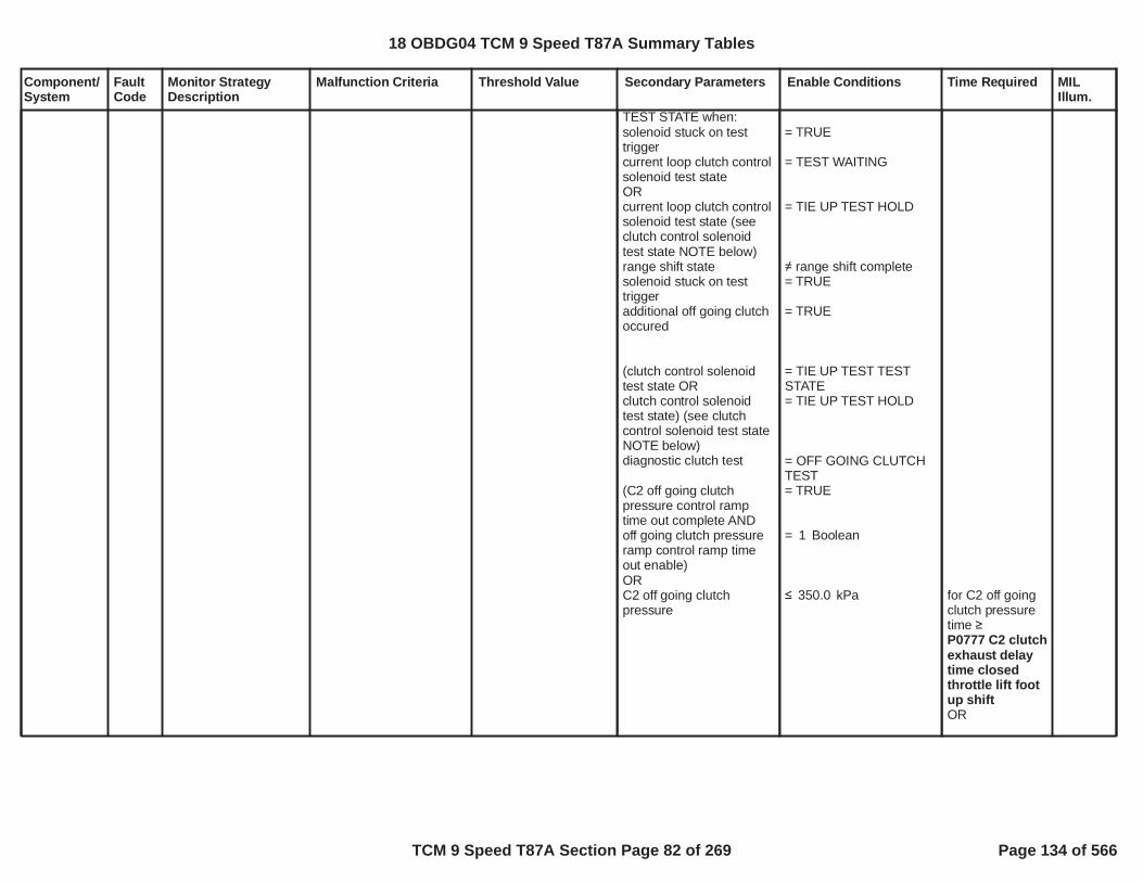
Component/System
FaultCode
Monitor StrategyDescription
Malfunction Criteria Threshold Value Secondary Parameters Enable Conditions Time Required MILIllum.
TEST STATE when:solenoid stuck on testtriggercurrent loop clutch controlsolenoid test stateORcurrent loop clutch controlsolenoid test state (seeclutch control solenoidtest state NOTE below)range shift statesolenoid stuck on testtriggeradditional off going clutchoccured
(clutch control solenoidtest state ORclutch control solenoidtest state) (see clutchcontrol solenoid test stateNOTE below)diagnostic clutch test
(C2 off going clutchpressure control ramptime out complete ANDoff going clutch pressureramp control ramp timeout enable)ORC2 off going clutchpressure
= TRUE
= TEST WAITING
= TIE UP TEST HOLD
range shift complete= TRUE
= TRUE
= TIE UP TEST TESTSTATE= TIE UP TEST HOLD
= OFF GOING CLUTCHTEST= TRUE
= Boolean1
kPa350.0 for C2 off goingclutch pressuretime P0777 C2 clutchexhaust delaytime closedthrottle lift footup shiftOR
18 OBDG04 TCM 9 Speed T87A Summary Tables
TCM 9 Speed T87A Section Page 82 of 269 Page 134 of 566

Component/System
FaultCode
Monitor StrategyDescription
Malfunction Criteria Threshold Value Secondary Parameters Enable Conditions Time Required MILIllum.
engine torqueprimary on coming clutchactiveprimary on coming controlstateclosed throttle lift foot upshift primary on comingclutch pressureORopen throttle power on upshift primary on comingclutch pressureORgarage shift primary on
Nm8,191.8= TRUE
clutch fill phase
kPa800.0
kPA800.0
kPa750.0
P0777 C2 clutchexhaust delaytime openthrottle poweron up shiftORP0777 C2 clutchexhaust delaytime garageshiftORP0777 C2 clutchexhaust delaytime closedthrottle downshiftORP0777 C2 clutchexhaust delaytime negativetorque up shiftORP0777 C2 clutchexhaust delaytime openthrottle powerdown shiftsee supportingtables
18 OBDG04 TCM 9 Speed T87A Summary Tables
TCM 9 Speed T87A Section Page 83 of 269 Page 135 of 566

Component/System
FaultCode
Monitor StrategyDescription
Malfunction Criteria Threshold Value Secondary Parameters Enable Conditions Time Required MILIllum.
coming clutch pressureORnegative torque up shiftprimary on coming clutchpressureORopen throttle power downshift primary on comingclutch pressureORclosed throttle down shiftprimary on coming clutchpressureC2 clutch slip speed valid,all speed sesnors arefunctional for lever nodeclucth slip speedcalculation
NOTE: Clutch controlsolenoid test state TIE UPTEST HOLD is necessary,as it is possible to havemultiple off going clutchesduring one automatictransmission shift. Clutchcontrol solenoid test stateis set to TIE UP TESTHOLD during anautomatic transmissionshift due to twoconditions:Current value of clutchcontrol solenoid test stateis TIE UP TEST TESTSTATE, when one offgoing clutch pressurecontrol solenoid stuck ondiagnostic monitor iscurrently executing.AND
kPa800.0
kPa800.0
kPa800.0
= TRUE
18 OBDG04 TCM 9 Speed T87A Summary Tables
TCM 9 Speed T87A Section Page 84 of 269 Page 136 of 566

Component/System
FaultCode
Monitor StrategyDescription
Malfunction Criteria Threshold Value Secondary Parameters Enable Conditions Time Required MILIllum.
That off going clutchpressure control solenoidstuck on diagnosticmonitor currentlyexecuting passes, thecorresponding clutch slipspeed clutch slip speedfail threshold.Once clutch controlsolenoid test state is setto TIE UP TEST HOLD, itremains TIE UP TESTHOLD during theautomatic transmissionshift, until:An additional off goingclutch occurs, asindicated by solenoidstuck on test trigger =TRUE, subsequentlyclutch control solenoidtest state is reset to TIEUP TEST TEST STATE, toallow the additionalcorresponding off goingclutch pressure controlsolenoid stuck ondiagnostic monitor toexecute.ORThe automatictransmission shiftcompletes, range shiftstate = range shiftcomplete.
NOTE: Startle mitigationis used to detectunintended vehicledeceleration due to aclutch pressure control
18 OBDG04 TCM 9 Speed T87A Summary Tables
TCM 9 Speed T87A Section Page 85 of 269 Page 137 of 566

Component/System
FaultCode
Monitor StrategyDescription
Malfunction Criteria Threshold Value Secondary Parameters Enable Conditions Time Required MILIllum.
solenoid stuck on failuremode that occurs duringsteady state gear, notduring an automatictransmission shift. Thestartle mitigation activethen forces thetransmission clutchpressure control systemto a safe gear or neutralstate, based on the activeand inactive clutches,when the unintendedvehicle decelerationoccurred. Once a safevehicle gear state isattained, the gear andclutch pressure controlsystem allows transitionsof the clutches on and off,to sequence automatictransmission shifts, singlestep shifts. As eachsingle step automatictransmission shift occursthe normal pressurecontrol solenoid stuck ondiagnostic monitorsexecute to verify whichclutch pressure controlsolenoid is in the stuck onfailure mode, allowing oneof the clutch pressurecontrol solenoid stuck onDTCs to set P0747,P0777, P0797, P2715,P2724, P2733, P2821.
DTCs not fault pending P0716 P0717 P0722P0723 P077C P077DP07BF P07C0
18 OBDG04 TCM 9 Speed T87A Summary Tables
TCM 9 Speed T87A Section Page 86 of 269 Page 138 of 566

Component/System
FaultCode
Monitor StrategyDescription
Malfunction Criteria Threshold Value Secondary Parameters Enable Conditions Time Required MILIllum.
DTCs not test fail this keyon
DTCs not fault active
P0707 P0708 P0746P0747 P0776 P0777P0796 P0797 P2714P2715 P2723 P2724P2732 P2733 P2820P2821
AcceleratorPedalFailureCrankSensor_FAP0707 P0708 P0716P0717 P07BF P07C0P0722 P0723 P077CP077D P172A P172BP176B P176C P176DP17C5 P17CC P17CDP17CE P17D3 P17D6P2805
18 OBDG04 TCM 9 Speed T87A Summary Tables
TCM 9 Speed T87A Section Page 87 of 269 Page 139 of 566

Component/System
FaultCode
Monitor StrategyDescription
Malfunction Criteria Threshold Value Secondary Parameters Enable Conditions Time Required MILIllum.
OutputSpeedSensorCircuit Low
P077C Controller specificanalog circuitdiagnoses thetransmission outputspeed sensor andwiring for a short toground fault bycomparing a voltagemeasurement tocontroller specificvoltage thresholds.
transmission output speedsesnor raw voltage,update fail time,12.5 millisecond updaterate
volts0.2500 0.5 impedance
between signal andcontroller ground) service mode $04 active
diagnostic monitor enableP077D fault activeservice fast learn
run crank voltagebattery voltage
P077C fault activeP077C test fail this key on
= FALSE= Boolean1= FALSE= FALSE
volts10.00volts10.00
= FALSE= FALSE
fail time 0.050seconds, updatefail count12.5 millisecondupdate rate
fail count 16counts12.5 millisecondupdate rate
run crank andbattery voltagetime 5.000seconds
Type A,1 Trips
18 OBDG04 TCM 9 Speed T87A Summary Tables
TCM 9 Speed T87A Section Page 88 of 269 Page 140 of 566

Component/System
FaultCode
Monitor StrategyDescription
Malfunction Criteria Threshold Value Secondary Parameters Enable Conditions Time Required MILIllum.
OutputSpeedSensorCircuit High
P077D Controller specificanalog circuitdiagnoses thetransmission outputspeed sensor andwiring for a short tovoltage fault bycomparing a voltagemeasurement tocontroller specificvoltage thresholds.
transmission output speedsesnor raw voltage,update fail time,12.5 millisecond updaterate
volts4.7500 0.5 impedance
between signal andcontroller power) service mode $04 active
diagnostic monitor enableP077C fault activeservice fast learn
run crank voltagebattery voltage
P077D fault activeP077D test fail this key on
= FALSE= Boolean1= FALSE= FALSE
volts10.00volts10.00
= FALSE= FALSE
fail time 0.050seconds, updatefail count12.5 millisecondupdate rate
fail count 16counts12.5 millisecondupdate rate
run crank andbattery voltagetime 5.000seconds
Type A,1 Trips
18 OBDG04 TCM 9 Speed T87A Summary Tables
TCM 9 Speed T87A Section Page 89 of 269 Page 141 of 566
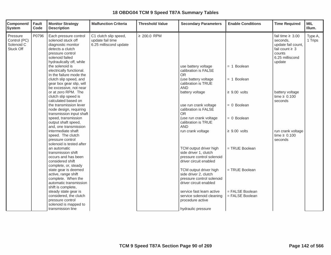
Component/System
FaultCode
Monitor StrategyDescription
Malfunction Criteria Threshold Value Secondary Parameters Enable Conditions Time Required MILIllum.
PressureControl (PC)Solenoid CStuck Off
P0796 Each pressure controlsolenoid stuck offdiagnostic monitordetects a clutchpressure controlsolenoid failedhydraulically off, whilethe solenoid iselectrically functional.In the failure mode theclutch slip speed, andgear box gear slip, willbe excessive, not nearor at zero RPM. Theclutch slip speed iscalculated based onthe transmission levernode design, requiringtransmission input shaftspeed, transmissionoutput shaft speed,and, one transmissionintermediate shaftspeed. The clutchpressure controlsolenoid is tested afteran automatictransmission shiftoccurs and has beenconsidered shiftcomplete, or, steadystate gear is deemedactive, range shiftcomplete. When theautomatic transmissionshift is complete,steady state gear isconsidered, the clutchpressure controlsolenoid is mapped totransmission line
C1 clutch slip speed,update fail time6.25 milliscond update
RPM200.0
use battery voltagecalibration is FALSEOR(use battery voltagecalibration is TRUEANDbattery voltage
use run crank voltagecalibration is FALSEOR(use run crank voltagecalibration is TRUEANDrun crank voltage
TCM output driver highside driver 1, clutchpressure control solenoiddriver circuit enabled
TCM output driver highside driver 2, clutchpressure control solenoiddriver circuit enabled
service fast learn activeservice solenoid cleaningprocedure active
hydraulic pressure
= Boolean1
= Boolean1
volts9.00
= Boolean0
= Boolean0
volts9.00
= TRUE Boolean
= TRUE Boolean
= FALSE Boolean= FALSE Boolean
fail time 3.00seconds,update fail count,fail count 3counts6.25 milliscondupdate
battery voltagetime 0.100seconds
run crank voltagetime 0.100seconds
Type A,1 Trips
18 OBDG04 TCM 9 Speed T87A Summary Tables
TCM 9 Speed T87A Section Page 90 of 269 Page 142 of 566

Component/System
FaultCode
Monitor StrategyDescription
Malfunction Criteria Threshold Value Secondary Parameters Enable Conditions Time Required MILIllum.
pressure control, whichnormally allows theclutch to maintain fulltorque holding capacityat the given enginecrankshaft torque, tomaintain true gearratio. When the clutchpressure controlsolenoid is failedhydraulically off, theclutch does notmaintain holdingcapacity at any enginecrankshaft torque, andthe clutch slip speed isuncontrollable. Theclutch pressure controlsolenoid test issuspended if the higherlevel safety startlemitigation function isactive. The safetystartle mitigationfunction is triggeredwhen a sudden vehicledeceleration occursdue to a clutchpressure controlsolenoid that has failedin the opposite sense,clutch pressure controlsolenoid failedhydraulically on, whilethe solenoid iselectrically functional,which must take priorityover any clutchpressure controlsolenoid stuck offdiagnostic monitor. Allclutch pressure control
available:engine speed
enable C3 clutch slipspeed fail compare when:diagnostic clutch test C3((startle mitigation activeOR(startle mitigation activeANDstartle mitigation gear))(see startle mitigationactive NOTE below)unintended decelerationfault pending ORunintended decelerationfault pending enableFASLE(startle mitigation)clutch steady stateadaptive activetransmission output shaftspeedC3 clutch slip speed valid,all speed sesnors arefunctional for lever nodeclucth slip speedcalculation
accelerator pedal positionengine speed
diagnostic clutch test C3set to HOLDING CLUTCHwhen:clutch solenoid test state
RPM400.0
= HOLDING CLUTCH= FALSE
= TRUE
initial startle mitigationgear
= FALSE
= Boolean0
= FALSE
RPM89.0
= TRUE
%2.00RPM1,500.0
= NEUTRAL TEST
engine speedtime engine speedtime fortransmissionhydraulicpressureavailablesee supportingtable
18 OBDG04 TCM 9 Speed T87A Summary Tables
TCM 9 Speed T87A Section Page 91 of 269 Page 143 of 566

Component/System
FaultCode
Monitor StrategyDescription
Malfunction Criteria Threshold Value Secondary Parameters Enable Conditions Time Required MILIllum.
solenoid stuck on/offdiagnostic monitors areemission MIL DTCs.System voltage mustbe normal, all clutchpressure controlsolenoid driver circuitsmust be functional, noclutch pressure controlsolenoid electrical orperformance faults canbe present, and nospeed sensor electricalor performance faultscan be present, or thea clutch pressurecontrol solenoid stuckoff test is disabled.This diagnostic monitoris relative to the GF9C3 CB38, or, GR10 C3CB123456R, clutchpressure controlsolenoid.
((startle mitigation activeOR(startle mitigation activeANDstartle mitigation gear))(see startle mitigationactive NOTE below)C3 clutch pressured map
clutch solenoid test stateset to NEUTRAL TESTwhen:test triggerinitialize range shiftcomplete time,whenrange shift state,range shift complete timemust time down to zerowhenrange shift complete
test trigger set to TRUE:enable forward gear ANDdirection requestORenable reverse gear ANDdirection requestcurrent loop test triggerclutch control solenoidtest staterange shift state
NOTE: startle mitigationactive is used to detectunintended decelerationdue to clutch pressurecontrol solenoid stuck on
= FALSE
= TRUE
initial startle mitigationgear
= mapped to linepressure, C3 clutchpressure has transtionedfrom off-applying-applied
= TRUE
range shift completed
= Boolean1= forward gear
= Boolean0= reverse gear= FALSE NEUTRAL TEST
= range shift completed
initialize rangeshift completetime = 1.000seconds,range shiftcomplete timemust time downto zerowhenrange shiftcomplete
18 OBDG04 TCM 9 Speed T87A Summary Tables
TCM 9 Speed T87A Section Page 92 of 269 Page 144 of 566

Component/System
FaultCode
Monitor StrategyDescription
Malfunction Criteria Threshold Value Secondary Parameters Enable Conditions Time Required MILIllum.
failure modes, the clutchpressure control solenoidstuck on DTCs beingP0747 P0777 P0797P2715 P2724 P2733P2821
DTCs not fault pending
DTCs not test fail this keyon
DTCs not fault active
P0716 P0717 P0722P0723 P077C P077DP07BF P07C0
P0707 P0708 P0746P0747 P0776 P0777P0796 P0797 P2714P2715 P2723 P2724P2732 P2733 P2820P2821
AcceleratorPedalFailureCrankSensor_FAP0707 P0708 P0716P0717 P07BF P07C0P0722 P0723 P077CP077D P172A P172BP176B P176C P176DP17C5 P17CC P17CDP17CE P17D3 P17D6P2805
18 OBDG04 TCM 9 Speed T87A Summary Tables
TCM 9 Speed T87A Section Page 93 of 269 Page 145 of 566

Component/System
FaultCode
Monitor StrategyDescription
Malfunction Criteria Threshold Value Secondary Parameters Enable Conditions Time Required MILIllum.
PressureControl (PC)Solenoid CStuck On
P0797 Each pressure controlsolenoid stuck ondiagnostic monitordetects a clutchpressure controlsolenoid failedhydraulically on, whilethe solenoid iselectrically functional.The clutch pressurecontrol solenoid istested during anautomatic transmissionshift by monitoring theoff going clutch slipspeed. With the clutchpressure controlsolenoid failed on, stillallowing hydraulicpressure to the clutchbeing commanded off,the intended off goingclutch continues tomaintain torquecapacity during thetransmission automaticshift. In the failuremode, the off goingclutch slip speed willremain near zero RPMwhen the clutchpressure controlsolenoid is commandedto an off pressure in thenormal operation torelease the holdingclutch. The clutch slipspeed is calculatedbased on thetransmission levernode design, requiring
shift type is power downshift,C3 clutch slip speedORshift type is not powerdown shift,C3 clutch slip speed
update fail time6.25 milliscond update
< RPM50.0
< RPM50.0
use battery voltagecalibration is FALSEOR(use battery voltagecalibration is TRUEANDbattery voltage
use run crank voltagecalibration is FALSEOR(use run crank voltagecalibration is TRUEANDrun crank voltage
TCM output driver highside driver 1, clutchpressure control solenoiddriver circuit enabled
= Boolean1
= Boolean1
volts9.00
= Boolean0
= Boolean0
volts9.00
= TRUE Boolean
shift type ispower downshift,fail time 0.800seconds,ORshift type is notpower downshift,fail time 0.150seconds,
update fail count,fail count 3counts6.25 milliscondupdate
battery voltagetime 0.100seconds
run crank voltagetime 0.100seconds
Type A,1 Trips
18 OBDG04 TCM 9 Speed T87A Summary Tables
TCM 9 Speed T87A Section Page 94 of 269 Page 146 of 566

Component/System
FaultCode
Monitor StrategyDescription
Malfunction Criteria Threshold Value Secondary Parameters Enable Conditions Time Required MILIllum.
transmission input shaftspeed, transmissionoutput shaft speed,and, one transmissionintermediate shaftspeed. As part of thepressure controlsolenoid stuck ondiagnostic monitor, thesafety startle mitigationfunction executes whenin steady state gear, noautomatic transmissionshift in progress. Thesafety startle mitigationfunction is triggeredwhen a sudden vehicledeceleration occursdue to a clutchpressure controlsolenoid that has failedhydraulically on, whilethe solenoid iselectrically functional.All clutch pressurecontrol solenoid stuckon diagnostic monitorsare emission MILDTCs. System voltagemust be normal, allclutch pressure controlsolenoid driver circuitsmust be functional, noclutch pressure controlsolenoid electrical orperformance faults canbe present, and nospeed sensor electricalor performance faultscan be present, or thea clutch pressurecontrol solenoid stuck
TCM output driver highside driver 2, clutchpressure control solenoiddriver circuit enabled
service fast learn activeservice solenoid cleaningprocedure active
hydraulic pressureavailable:engine speed
transmission output shaftspeed
set solenoid stuck on testtrigger to TRUE when:clutch pressure controlsolenoid stuck off stuckintrusive shift requeststartle mitigation active(see startle mitigationactive NOTE below)clutch control solenoidtest stateclutch control solenoidtest state (see clutchcontrol solenoid test stateNOTE below)initialize active clutchcontroller (clutch controlprocessing in process ofsequencing clutches on
= TRUE Boolean
= FALSE Boolean= FALSE Boolean
RPM400.0
RPM89.0
= FALSE
= FALSE
TIE UP TEST TESTSTATE TIE UP TEST HOLD
= TRUE
engine speedtime engine speedtime fortransmissionhydraulicpressureavailablesee supportingtable
18 OBDG04 TCM 9 Speed T87A Summary Tables
TCM 9 Speed T87A Section Page 95 of 269 Page 147 of 566

Component/System
FaultCode
Monitor StrategyDescription
Malfunction Criteria Threshold Value Secondary Parameters Enable Conditions Time Required MILIllum.
on test is disabled.This diagnostic monitoris relative to the GF9C3 CB38, or, GR10 C3CB123456R, clutchpressure controlsolenoid.
and off for auto trans shift)(shift type enable forstaged steady state shift -shift in process when newshift type occurs -interrupted shiftORshift type enable forgarage shiftORshift type enable fornegative torque up shiftORshift type enable for openthrottle power on up shiftORshift type enable forclosed throttle down shiftORshift type enable for openthrottle power down shiftORshift type enable forclosed throttle lift foot upshift )ORclutch control solenoidtest stateclutch control solenoidtest state (see clutchcontrol solenoid test stateNOTE below)transition clutch controlleractive clutch controller(staged steady sate shift -shift not in process, nonew shift type occuring,no interrupted shift)
set clutch control solenoidtest state to TIE UP TEST
= Boolean0
= Boolean0
= Boolean1
= Boolean1
= Boolean1
= Boolean1
= Boolean0
= TIE UP TEST TESTSTATE= TIE UP TEST HOLD
= TRUE staged steady state
18 OBDG04 TCM 9 Speed T87A Summary Tables
TCM 9 Speed T87A Section Page 96 of 269 Page 148 of 566

Component/System
FaultCode
Monitor StrategyDescription
Malfunction Criteria Threshold Value Secondary Parameters Enable Conditions Time Required MILIllum.
TEST STATE when:solenoid stuck on testtriggercurrent loop clutch controlsolenoid test stateORcurrent loop clutch controlsolenoid test state (seeclutch control solenoidtest state NOTE below)range shift statesolenoid stuck on testtriggeradditional off going clutchoccured
(clutch control solenoidtest state ORclutch control solenoidtest state) (see clutchcontrol solenoid test stateNOTE below)diagnostic clutch test
(C3 off going clutchpressure control ramptime out complete ANDoff going clutch pressureramp control ramp timeout enable)ORC3 off going clutchpressure
= TRUE
= TEST WAITING
= TIE UP TEST HOLD
range shift complete= TRUE
= TRUE
= TIE UP TEST TESTSTATE= TIE UP TEST HOLD
= OFF GOING CLUTCHTEST= TRUE
= Boolean1
kPa350.0 for C3 off goingclutch pressuretime P0797 C3 clutchexhaust delaytime closedthrottle lift footup shiftOR
18 OBDG04 TCM 9 Speed T87A Summary Tables
TCM 9 Speed T87A Section Page 97 of 269 Page 149 of 566

Component/System
FaultCode
Monitor StrategyDescription
Malfunction Criteria Threshold Value Secondary Parameters Enable Conditions Time Required MILIllum.
engine torqueprimary on coming clutchactiveprimary on coming controlstateclosed throttle lift foot upshift primary on comingclutch pressureORopen throttle power on upshift primary on comingclutch pressureORgarage shift primary on
Nm8,191.8= TRUE
clutch fill phase
kPa500.0
kPA500.0
kPa750.0
P0797 C3 clutchexhaust delaytime openthrottle poweron up shiftORP0797 C3clutchexhaust delaytime garageshiftORP0797 C3 clutchexhaust delaytime closedthrottle downshiftORP0797 C3 clutchexhaust delaytime negativetorque up shiftORP0797 C3 clutchexhaust delaytime openthrottle powerdown shiftsee supportingtables
18 OBDG04 TCM 9 Speed T87A Summary Tables
TCM 9 Speed T87A Section Page 98 of 269 Page 150 of 566

Component/System
FaultCode
Monitor StrategyDescription
Malfunction Criteria Threshold Value Secondary Parameters Enable Conditions Time Required MILIllum.
coming clutch pressureORnegative torque up shiftprimary on coming clutchpressureORopen throttle power downshift primary on comingclutch pressureORclosed throttle down shiftprimary on coming clutchpressureC3 clutch slip speed valid,all speed sesnors arefunctional for lever nodeclucth slip speedcalculation
NOTE: Clutch controlsolenoid test state TIE UPTEST HOLD is necessary,as it is possible to havemultiple off going clutchesduring one automatictransmission shift. Clutchcontrol solenoid test stateis set to TIE UP TESTHOLD during anautomatic transmissionshift due to twoconditions:Current value of clutchcontrol solenoid test stateis TIE UP TEST TESTSTATE, when one offgoing clutch pressurecontrol solenoid stuck ondiagnostic monitor iscurrently executing.AND
kPa500.0
kPa500.0
kPa500.0
= TRUE
18 OBDG04 TCM 9 Speed T87A Summary Tables
TCM 9 Speed T87A Section Page 99 of 269 Page 151 of 566

Component/System
FaultCode
Monitor StrategyDescription
Malfunction Criteria Threshold Value Secondary Parameters Enable Conditions Time Required MILIllum.
That off going clutchpressure control solenoidstuck on diagnosticmonitor currentlyexecuting passes, thecorresponding clutch slipspeed clutch slip speedfail threshold.Once clutch controlsolenoid test state is setto TIE UP TEST HOLD, itremains TIE UP TESTHOLD during theautomatic transmissionshift, until:An additional off goingclutch occurs, asindicated by solenoidstuck on test trigger =TRUE, subsequentlyclutch control solenoidtest state is reset to TIEUP TEST TEST STATE, toallow the additionalcorresponding off goingclutch pressure controlsolenoid stuck ondiagnostic monitor toexecute.ORThe automatictransmission shiftcompletes, range shiftstate = range shiftcomplete.
NOTE: Startle mitigationis used to detectunintended vehicledeceleration due to aclutch pressure control
18 OBDG04 TCM 9 Speed T87A Summary Tables
TCM 9 Speed T87A Section Page 100 of 269 Page 152 of 566

Component/System
FaultCode
Monitor StrategyDescription
Malfunction Criteria Threshold Value Secondary Parameters Enable Conditions Time Required MILIllum.
solenoid stuck on failuremode that occurs duringsteady state gear, notduring an automatictransmission shift. Thestartle mitigation activethen forces thetransmission clutchpressure control systemto a safe gear or neutralstate, based on the activeand inactive clutches,when the unintendedvehicle decelerationoccurred. Once a safevehicle gear state isattained, the gear andclutch pressure controlsystem allows transitionsof the clutches on and off,to sequence automatictransmission shifts, singlestep shifts. As eachsingle step automatictransmission shift occursthe normal pressurecontrol solenoid stuck ondiagnostic monitorsexecute to verify whichclutch pressure controlsolenoid is in the stuck onfailure mode, allowing oneof the clutch pressurecontrol solenoid stuck onDTCs to set P0747,P0777, P0797, P2715,P2724, P2733, P2821.
DTCs not fault pending P0716 P0717 P0722P0723 P077C P077DP07BF P07C0
18 OBDG04 TCM 9 Speed T87A Summary Tables
TCM 9 Speed T87A Section Page 101 of 269 Page 153 of 566

Component/System
FaultCode
Monitor StrategyDescription
Malfunction Criteria Threshold Value Secondary Parameters Enable Conditions Time Required MILIllum.
DTCs not test fail this keyon
DTCs not fault active
P0707 P0708 P0746P0747 P0776 P0777P0796 P0797 P2714P2715 P2723 P2724P2732 P2733 P2820P2821
AcceleratorPedalFailureCrankSensor_FAP0707 P0708 P0716P0717 P07BF P07C0P0722 P0723 P077CP077D P172A P172BP176B P176C P176DP17C5 P17CC P17CDP17CE P17D3 P17D6P2805
18 OBDG04 TCM 9 Speed T87A Summary Tables
TCM 9 Speed T87A Section Page 102 of 269 Page 154 of 566

Component/System
FaultCode
Monitor StrategyDescription
Malfunction Criteria Threshold Value Secondary Parameters Enable Conditions Time Required MILIllum.
Input/TurbineSpeedSensor ACircuit Low
P07BF Controller specificanalog circuitdiagnoses thetransmission input/turbine speed sensorand wiring for a short toground fault bycomparing a voltagemeasurement tocontroller specificvoltage thresholds.
transmission intput/turbinespeed sesnor raw voltage,update fail time,12.5 millisecond updaterate
volts0.2500 0.5 impedance
between signal andcontroller ground) service mode $04 active
diagnostic monitor enableP07C0 fault activeservice fast learn
run crank voltagebattery voltage
P07BF fault activeP07BF test fail this key on
= FALSE= Boolean1= FALSE= FALSE
volts10.00volts10.00
= FALSE= FALSE
fail time 0.050seconds, updatefail count12.5 millisecondupdate rate
fail count 16counts12.5 millisecondupdate rate
run crank andbattery voltagetime 5.000seconds
Type A,1 Trips
18 OBDG04 TCM 9 Speed T87A Summary Tables
TCM 9 Speed T87A Section Page 103 of 269 Page 155 of 566

Component/System
FaultCode
Monitor StrategyDescription
Malfunction Criteria Threshold Value Secondary Parameters Enable Conditions Time Required MILIllum.
Input/TurbineSpeedSensor ACircuit High
P07C0 Controller specificanalog circuitdiagnoses thetransmission input/turbine speed sensorand wiring for a short tovoltage fault bycomparing a voltagemeasurement tocontroller specificvoltage thresholds.
transmission input/turbinespeed sesnor raw voltage,update fail time,12.5 millisecond updaterate
volts4.7500 0.5 impedance
between signal andcontroller power) service mode $04 active
diagnostic monitor enableP07BF fault activeservice fast learn
run crank voltagebattery voltage
P07C0 fault activeP07C0 test fail this key on
= FALSE= Boolean1= FALSE= FALSE
volts10.00volts10.00
= FALSE= FALSE
fail time 0.050seconds, updatefail count12.5 millisecondupdate rate
fail count 16counts12.5 millisecondupdate rate
run crank andbattery voltagetime 5.000seconds
Type A,1 Trips
18 OBDG04 TCM 9 Speed T87A Summary Tables
TCM 9 Speed T87A Section Page 104 of 269 Page 156 of 566

Component/System
FaultCode
Monitor StrategyDescription
Malfunction Criteria Threshold Value Secondary Parameters Enable Conditions Time Required MILIllum.
switch stateupdate fail time 1100 millisecond updaterate
= tap up (upshift) stateactive
service mode $04 activediagnostic monitor enable
run crank voltage
run crank voltageP1761 fault activeP0826 fault activeP0826 test fail this key onP0826 fault pending(P0815 fault active ORP0815 fault active test failthis key on)PRNDL range changetimePRNDL in range:D1 ORD2 ORD3 ORD4 ORD5 ORD6 ORD7 ORD8 ORD9 ORD10 ORNEUTRAL ORPARK ORREVERSE
DTCs not fault pending
= FALSE= Boolean1
volts5.00
volts9.00= FALSE= FALSE= FALSE= FALSE= FALSE= FALSE
= Boolean1= Boolean1= Boolean1= Boolean1= Boolean1= Boolean1= Boolean1= Boolean1= Boolean1= Boolean0= Boolean0= Boolean0= Boolean0
Transmission Shift LeverPosition Validity
fail time 1 1.00seconds
run crank voltagetime 25milliseconds
seconds1.00
UpshiftSwitchCircuit
P0815 Diagnoses the state ofthe upshift switchcircuit, stuck in thestate "tap up" (upshift)active.
SpecialType C
switch stateupdate fail time 2100 millisecond updaterate
= tap up (upshift) stateactive
service mode $04 activediagnostic monitor enable
run crank voltage
run crank voltageP1761 fault activeP0826 fault activeP0826 test fail this key on
= FALSE= Boolean1
volts5.00
volts9.00= FALSE= FALSE= FALSE
fail time 2 seconds120.00
run crank voltagetime 25milliseconds
18 OBDG04 TCM 9 Speed T87A Summary Tables
TCM 9 Speed T87A Section Page 105 of 269 Page 157 of 566

Component/System
FaultCode
Monitor StrategyDescription
Malfunction Criteria Threshold Value Secondary Parameters Enable Conditions Time Required MILIllum.
P0826 fault pending(P0815 fault active ORP0815 fault active test failthis key on)PRNDL range changetimePRNDL in range:D1 ORD2 ORD3 ORD4 ORD5 ORD6 ORD7 ORD8 ORD9 ORD10 ORNEUTRAL ORPARK ORREVERSE
DTCs not fault pending
= FALSE= FALSE= FALSE
= Boolean1= Boolean1= Boolean1= Boolean1= Boolean1= Boolean1= Boolean1= Boolean1= Boolean1= Boolean0= Boolean0= Boolean0= Boolean0
Transmission Shift LeverPosition Validity
seconds1.00
18 OBDG04 TCM 9 Speed T87A Summary Tables
TCM 9 Speed T87A Section Page 106 of 269 Page 158 of 566

Component/System
FaultCode
Monitor StrategyDescription
Malfunction Criteria Threshold Value Secondary Parameters Enable Conditions Time Required MILIllum.
switch stateupdate fail time 1100 millisecond updaterate
= tap down (downshift)state active
service mode $04 activediagnostic monitor enable
run crank voltage
run crank voltageP1761 fault activeP0826 fault activeP0826 test fail this key onP0826 fault pending(P0816 fault active ORP0816 fault active test failthis key on)PRNDL range changetimePRNDL in range:D1 ORD2 ORD3 ORD4 ORD5 ORD6 ORD7 ORD8 ORD9 ORD10 ORNEUTRAL ORPARK ORREVERSE
DTCs not fault pending
= FALSE= Boolean1
volts5.00
volts9.00= FALSE= FALSE= FALSE= FALSE= FALSE= FALSE
= Boolean1= Boolean1= Boolean1= Boolean1= Boolean1= Boolean1= Boolean1= Boolean1= Boolean1= Boolean0= Boolean0= Boolean0= Boolean0
Transmission Shift LeverPosition Validity
fail time 1 seconds1.00
run crank voltagetime 25milliseconds
seconds1.00
DownshiftSwitchCircuit
P0816 Diagnoses the state ofthe downshift switchcircuit, stuck in thestate "tapdown" (downshift)active.
SpecialType C
switch stateupdate fail time 2100 millisecond updaterate
= tap down (downshift)state active
service mode $04 activediagnostic monitor enable
run crank voltage
run crank voltageP1761 fault activeP0826 fault activeP0826 test fail this key on
= FALSE= Boolean1
volts5.00
volts9.00= FALSE= FALSE= FALSE
fail time 2 seconds120.00
run crank voltagetime 25milliseconds
18 OBDG04 TCM 9 Speed T87A Summary Tables
TCM 9 Speed T87A Section Page 107 of 269 Page 159 of 566

Component/System
FaultCode
Monitor StrategyDescription
Malfunction Criteria Threshold Value Secondary Parameters Enable Conditions Time Required MILIllum.
P0826 fault pending(P0816 fault active ORP0816 fault active test failthis key on)PRNDL range changetimePRNDL in range:D1 ORD2 ORD3 ORD4 ORD5 ORD6 ORD7 ORD8 ORD9 ORD10 ORNEUTRAL ORPARK ORREVERSE
DTCs not fault pending
= FALSE= FALSE= FALSE
= Boolean1= Boolean1= Boolean1= Boolean1= Boolean1= Boolean1= Boolean1= Boolean1= Boolean1= Boolean0= Boolean0= Boolean0= Boolean0
Transmission Shift LeverPosition Validity
seconds1.00
18 OBDG04 TCM 9 Speed T87A Summary Tables
TCM 9 Speed T87A Section Page 108 of 269 Page 160 of 566

Component/System
FaultCode
Monitor StrategyDescription
Malfunction Criteria Threshold Value Secondary Parameters Enable Conditions Time Required MILIllum.
Up andDown ShiftSwitchCircuit
P0826 Diagnoses the state ofthe upshift/downshiftswitch circuit at anillegal voltage, voltageout of range.
switch stateupdate fail time100 millisecond updaterate
= illegal (voltage out ofrange)
service mode $04 activediagnostic monitor enable
run crank voltage
run crank voltageP1761 fault active(P0826 fault active ORP0826 fault active test failthis key on)
= FALSE= Boolean1
volts5.00
volts9.00= FALSE= FALSE= FALSE
fail time 60.00seconds
run crank voltagetime 25milliseconds
SpecialType C
18 OBDG04 TCM 9 Speed T87A Summary Tables
TCM 9 Speed T87A Section Page 109 of 269 Page 161 of 566

Component/System
FaultCode
Monitor StrategyDescription
Malfunction Criteria Threshold Value Secondary Parameters Enable Conditions Time Required MILIllum.
PressureControl (PC)Solenoid AControlCircuit Open
P0960 Controller specificcircuit diagnoses 9speed CB123456 or 10speed CB123456Rclutch solenoid for anopen circuit failure bycomparing a voltagemeasurement tocontroller specificvoltage thresholds.
Voltage measurementoutside of controllerspecific acceptable rangeindicates an open circuit
Controller specific circuitvoltage thresholds are setto meet the followingcontroller specification foran open circuit
Increment fail time
200 K impedancebetween signal andcontroller ground
battery voltage
run crank voltageORaccessory voltage active
diagnostic monitor enablecalibration
volts and9.00volts32.00
volts5.00
= TRUE
= Boolean1
seconds1.000
25 milliseconds
12.5 milliseconds
fail time 0.300seconds out ofsample time
seconds0.500
Type A,1 Trips
18 OBDG04 TCM 9 Speed T87A Summary Tables
TCM 9 Speed T87A Section Page 110 of 269 Page 162 of 566

Component/System
FaultCode
Monitor StrategyDescription
Malfunction Criteria Threshold Value Secondary Parameters Enable Conditions Time Required MILIllum.
PressureControl (PC)Solenoid AControlCircuit LowVoltage
P0962 Controller specificcircuit diagnoses 9speed CB123456 or 10speed CB123456Rclutch solenoid for aground short circuitfailure by comparing avoltage measurementto controller specificvoltage thresholds.
Voltage measurementoutside of controllerspecific acceptable rangeindicates a ground short
Controller specific circuitvoltage thresholds are setto meet the followingcontroller specification fora ground short
Increment fail time
0.5 impedancebetween signal andcontroller ground
battery voltage
run crank voltageORaccessory voltage active
diagnostic monitor enablecalibration
volts and9.00volts32.00
volts5.00
= TRUE
= Boolean1
seconds1.000
25 milliseconds
12.5 milliseconds
fail time 0.300seconds out ofsample time
seconds0.500
Type A,1 Trips
18 OBDG04 TCM 9 Speed T87A Summary Tables
TCM 9 Speed T87A Section Page 111 of 269 Page 163 of 566

Component/System
FaultCode
Monitor StrategyDescription
Malfunction Criteria Threshold Value Secondary Parameters Enable Conditions Time Required MILIllum.
PressureControl (PC)Solenoid AControlCircuit HighVoltage
P0963 Controller specificcircuit diagnoses 9speed CB123456 or 10speed CB123456Rclutch solenoid for ashort to voltage circuitfailure by comparing avoltage measurementto controller specificvoltage thresholds.
Voltage measurementoutside of controllerspecific acceptable rangeindicates a short tovoltage
Controller specific circuitvoltage thresholds are setto meet the followingcontroller specification fora short to voltage
Increment fail time
0.5 impedancebetween signal andcontroller voltagesource
battery voltage
run crank voltageORaccessory voltage active
diagnostic monitor enablecalibration
volts and9.00volts32.00
volts5.00
= TRUE
= Boolean1
seconds1.000
25 milliseconds
12.5 milliseconds
fail time 0.300seconds out ofsample time
seconds0.500
Type A,1 Trips
18 OBDG04 TCM 9 Speed T87A Summary Tables
TCM 9 Speed T87A Section Page 112 of 269 Page 164 of 566

Component/System
FaultCode
Monitor StrategyDescription
Malfunction Criteria Threshold Value Secondary Parameters Enable Conditions Time Required MILIllum.
PressureControl (PC)Solenoid BControlCircuit Open
P0964 Controller specificcircuit diagnoses 9speed CB29 or 10speed CB128910Rclutch solenoid for anopen circuit failure bycomparing a voltagemeasurement tocontroller specificvoltage thresholds.
Voltage measurementoutside of controllerspecific acceptable rangeindicates an open circuit
Controller specific circuitvoltage thresholds are setto meet the followingcontroller specification foran open circuit
Increment fail time
200 K impedancebetween signal andcontroller ground
battery voltage
run crank voltageORaccessory voltage active
diagnostic monitor enablecalibration
volts and9.00volts32.00
volts5.00
= TRUE
= Boolean1
seconds1.000
25 milliseconds
12.5 milliseconds
fail time 0.300seconds out ofsample time
seconds0.500
Type A,1 Trips
18 OBDG04 TCM 9 Speed T87A Summary Tables
TCM 9 Speed T87A Section Page 113 of 269 Page 165 of 566

Component/System
FaultCode
Monitor StrategyDescription
Malfunction Criteria Threshold Value Secondary Parameters Enable Conditions Time Required MILIllum.
PressureControl (PC)Solenoid BControlCircuit LowVoltage
P0966 Controller specificcircuit diagnoses 9speed CB123456 or 10speed CB123456Rclutch solenoid for aground short circuitfailure by comparing avoltage measurementto controller specificvoltage thresholds.
Voltage measurementoutside of controllerspecific acceptable rangeindicates a ground short
Controller specific circuitvoltage thresholds are setto meet the followingcontroller specification fora ground short
Increment fail time
0.5 impedancebetween signal andcontroller ground
battery voltage
run crank voltageORaccessory voltage active
diagnostic monitor enablecalibration
volts and9.00volts32.00
volts5.00
= TRUE
= Boolean1
seconds1.000
25 milliseconds
12.5 milliseconds
fail time 0.300seconds out ofsample time
seconds0.500
Type A,1 Trips
18 OBDG04 TCM 9 Speed T87A Summary Tables
TCM 9 Speed T87A Section Page 114 of 269 Page 166 of 566

Component/System
FaultCode
Monitor StrategyDescription
Malfunction Criteria Threshold Value Secondary Parameters Enable Conditions Time Required MILIllum.
PressureControl (PC)Solenoid BControlCircuit HighVoltage
P0967 Controller specificcircuit diagnoses 9speed CB123456 or 10speed CB123456Rclutch solenoid for ashort to voltage circuitfailure by comparing avoltage measurementto controller specificvoltage thresholds.
Voltage measurementoutside of controllerspecific acceptable rangeindicates a short tovoltage
Controller specific circuitvoltage thresholds are setto meet the followingcontroller specification fora short to voltage
Increment fail time
0.5 impedancebetween signal andcontroller voltagesource
battery voltage
run crank voltageORaccessory voltage active
diagnostic monitor enablecalibration
volts and9.00volts32.00
volts5.00
= TRUE
= Boolean1
seconds1.000
25 milliseconds
12.5 milliseconds
fail time 0.300seconds out ofsample time
seconds0.500
Type A,1 Trips
18 OBDG04 TCM 9 Speed T87A Summary Tables
TCM 9 Speed T87A Section Page 115 of 269 Page 167 of 566

Component/System
FaultCode
Monitor StrategyDescription
Malfunction Criteria Threshold Value Secondary Parameters Enable Conditions Time Required MILIllum.
PressureControl (PC)Solenoid CControlCircuit Open
P0968 Controller specificcircuit diagnoses 9speed CB38 or 10speed C23457910clutch solenoid for anopen circuit failure bycomparing a voltagemeasurement tocontroller specificvoltage thresholds.
Voltage measurementoutside of controllerspecific acceptable rangeindicates an open circuit
Controller specific circuitvoltage thresholds are setto meet the followingcontroller specification foran open circuit
Increment fail time
200 K impedancebetween signal andcontroller ground
battery voltage
run crank voltageORaccessory voltage active
diagnostic monitor enablecalibration
volts and9.00volts32.00
volts5.00
= TRUE
= Boolean1
seconds1.000
25 milliseconds
12.5 milliseconds
fail time 0.300seconds out ofsample time
seconds0.500
Type A,1 Trips
18 OBDG04 TCM 9 Speed T87A Summary Tables
TCM 9 Speed T87A Section Page 116 of 269 Page 168 of 566

Component/System
FaultCode
Monitor StrategyDescription
Malfunction Criteria Threshold Value Secondary Parameters Enable Conditions Time Required MILIllum.
PressureControl (PC)Solenoid CControlCircuit LowVoltage
P0970 Controller specificcircuit diagnoses 9speed CB38 or 10speed C23457910clutch solenoid for aground short circuitfailure by comparing avoltage measurementto controller specificvoltage thresholds.
Voltage measurementoutside of controllerspecific acceptable rangeindicates a ground short
Controller specific circuitvoltage thresholds are setto meet the followingcontroller specification fora ground short
Increment fail time
0.5 impedancebetween signal andcontroller ground
battery voltage
run crank voltageORaccessory voltage active
diagnostic monitor enablecalibration
volts and9.00volts32.00
volts5.00
= TRUE
= Boolean1
seconds1.000
25 milliseconds
12.5 milliseconds
fail time 0.300seconds out ofsample time
seconds0.500
Type A,1 Trips
18 OBDG04 TCM 9 Speed T87A Summary Tables
TCM 9 Speed T87A Section Page 117 of 269 Page 169 of 566

Component/System
FaultCode
Monitor StrategyDescription
Malfunction Criteria Threshold Value Secondary Parameters Enable Conditions Time Required MILIllum.
PressureControl (PC)Solenoid CControlCircuit HighVoltage
P0971 Controller specificcircuit diagnoses 9speed CB38 or 10speed C23457910clutch solenoid for ashort to voltage circuitfailure by comparing avoltage measurementto controller specificvoltage thresholds.
Voltage measurementoutside of controllerspecific acceptable rangeindicates a short tovoltage
Controller specific circuitvoltage thresholds are setto meet the followingcontroller specification fora short to voltage
Increment fail time
0.5 impedancebetween signal andcontroller voltagesource
battery voltage
run crank voltageORaccessory voltage active
diagnostic monitor enablecalibration
volts and9.00volts32.00
volts5.00
= TRUE
= Boolean1
seconds1.000
25 milliseconds
12.5 milliseconds
fail time 0.300seconds out ofsample time
seconds0.500
Type A,1 Trips
18 OBDG04 TCM 9 Speed T87A Summary Tables
TCM 9 Speed T87A Section Page 118 of 269 Page 170 of 566

Component/System
FaultCode
Monitor StrategyDescription
Malfunction Criteria Threshold Value Secondary Parameters Enable Conditions Time Required MILIllum.
ControlModuleSerialPeripheralInterfaceBus 2
P16E9 This DTC detectsintermitent andcontinuous invalid SPImessages. This isbased on the detectionof missing or invalidreceive message withinthe main processorbefore receiving a validmessage.
This function detects aserial communicationsfault based upon thedetection of missing orinvalid (receive) messagewithin the secondaryprocessor before andafter receiving a validmessage.
Run/Crank voltage >6.41
Number ofinvalid messages> OR64.00Amount of timebefore firstmessagereceived sinceinitialization >0.19countscontinuous; 12.5ms /count in theTCM secondaryprocessor
Type A,1 Trips
18 OBDG04 TCM 9 Speed T87A Summary Tables
TCM 9 Speed T87A Section Page 119 of 269 Page 171 of 566

Component/System
FaultCode
Monitor StrategyDescription
Malfunction Criteria Threshold Value Secondary Parameters Enable Conditions Time Required MILIllum.
This function detects aserial communicationsfault based upon thedetection of missing orinvalid (receive) messagewithin the main processorbefore receiving a validmessage.
Run/Crank voltage >6.41
/10016countscontinuous; 12.5ms /count in theTCM mainprocessor
ControlModuleSerialPeripheralInterfaceBus 1
P16F0 This DTC detectsintermitent andcontinuous invalid SPImessages. This isbased on the detectionof missing or invalidreceive message withinthe main processorbefore receiving a validmessage.
Type A,1 Trips
This function detects aserial communicationsfault based upon thedetection of missing orinvalid (receive) messagewithin the main processorafter receiving a validmessage.
Run/Crank voltage >6.41
8/16
countscontinuous; 12.5ms /count in theTCM mainprocessor
18 OBDG04 TCM 9 Speed T87A Summary Tables
TCM 9 Speed T87A Section Page 120 of 269 Page 172 of 566
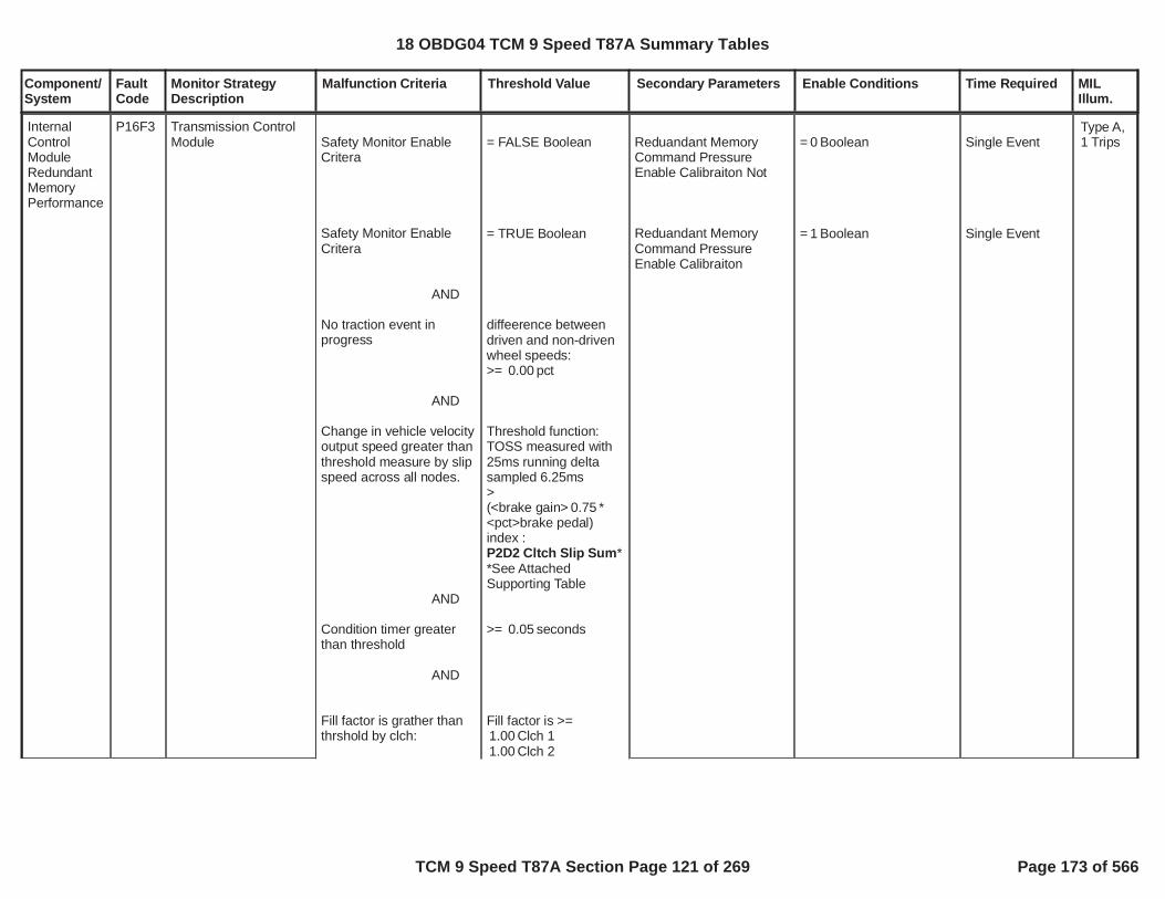
Component/System
FaultCode
Monitor StrategyDescription
Malfunction Criteria Threshold Value Secondary Parameters Enable Conditions Time Required MILIllum.
Safety Monitor EnableCritera
Safety Monitor EnableCritera
AND
No traction event inprogress
AND
Change in vehicle velocityoutput speed greater thanthreshold measure by slipspeed across all nodes.
AND
Condition timer greaterthan threshold
AND
Fill factor is grather thanthrshold by clch:
= FALSE Boolean
= TRUE Boolean
diffeerence betweendriven and non-drivenwheel speeds:>= pct0.00
Threshold function:TOSS measured with25ms running deltasampled 6.25ms>(<brake gain> *0.75<pct>brake pedal)index :
*P2D2 Cltch Slip Sum*See AttachedSupporting Table
>= seconds0.05
Fill factor is >=Clch 11.00Clch 21.00
Reduandant MemoryCommand PressureEnable Calibraiton Not
Reduandant MemoryCommand PressureEnable Calibraiton
= Boolean0
= Boolean1
Single Event
Single Event
InternalControlModuleRedundantMemoryPerformance
P16F3 Transmission ControlModule
Type A,1 Trips
18 OBDG04 TCM 9 Speed T87A Summary Tables
TCM 9 Speed T87A Section Page 121 of 269 Page 173 of 566

Component/System
FaultCode
Monitor StrategyDescription
Malfunction Criteria Threshold Value Secondary Parameters Enable Conditions Time Required MILIllum.
Command clutch pressureon released clutch greaterthan threshold
AND
AND
Clch 31.00Clch 41.00Clch 51.00Clch 61.00Clch 71.00
Calucualte clutch pressby clutch:
(PCS cmnd pressure -pressure offset ) *0.00
( C1 reg gain,1.00C2 reg gain,1.00C3 reg gain,1.51C4 reg gain,2.25C5 reg gain,1.00C6 reg gain,1.00C7 reg gain)1.00
Subtract return spring :adapt value fromABOVE PCS pressure--> value 1
Compare Thresholdsfor clutches by gear:<=P2D2 Decel Pressure- C1<=P2D2 Decel Pressure- C2<=P2D2 Decel Pressure- C3<=P2D2 Decel Pressure- C4<=
18 OBDG04 TCM 9 Speed T87A Summary Tables
TCM 9 Speed T87A Section Page 122 of 269 Page 174 of 566

Component/System
FaultCode
Monitor StrategyDescription
Malfunction Criteria Threshold Value Secondary Parameters Enable Conditions Time Required MILIllum.
AND
Check Min # of clutchesby attained gear and bycomanded gear takelower of the 2 values.
AND
*Monitor is disabled ifFault Active or codes for:Speeds Sensors 1/2/3,High Side Drivers 1/2 orservice fast learn active.
P2D2 Decel Pressure- C5<=P2D2 Decel Pressure- C6<=P2D2 Decel Pressure- C7*See AttachedSupporting Tables
<= NumClchTieUp
Confirmation of tie upcapacity clutches. -This is done by takingvalue 1 above andsubtracting returnspring and confirmingfill factor above tablevalue --> add up # ofclutches calucualted asON.
*See AttachedSupporting Tables:
Reduandant Memory Single Event
18 OBDG04 TCM 9 Speed T87A Summary Tables
TCM 9 Speed T87A Section Page 123 of 269 Page 175 of 566

Component/System
FaultCode
Monitor StrategyDescription
Malfunction Criteria Threshold Value Secondary Parameters Enable Conditions Time Required MILIllum.
Safety Monitor EnableCritera
AND
Safety Monitor EnableCritera
Command gear too lowfor present vehcle velocityand pedal position
IF (incorrect gear stillcommanded)
THEN
= FALSE Boolean
= TRUE Boolean
Commanded GearThreshold by vehiclevelocity:
<= MaxSpdGr1<= MaxSpdGr2<= MaxSpdGr3<= MaxSpdGr4<= MaxSpdGr5<= MaxSpdGr6<= MaxSpdGr7<= MaxSpdGr8<= MaxSpdGr9<= MaxSpdGr10
RPR (return toprevious range ifpossible) Input AccelPosition and Vehcilespeed
-->MinGearAllowedreturn min gear.
seconds hold in5.00gear before repeat upto max # of times( cnt of times that3.00can RPR)
Command Gear EnableCalibraiton Not
Reduandant MemoryCommand Gear EnableCalibraiton
= Boolean0
= Boolean1
18 OBDG04 TCM 9 Speed T87A Summary Tables
TCM 9 Speed T87A Section Page 124 of 269 Page 176 of 566

Component/System
FaultCode
Monitor StrategyDescription
Malfunction Criteria Threshold Value Secondary Parameters Enable Conditions Time Required MILIllum.
*Monitor is diabled if:TISS FA or TOSS FA,SFL or HSD 1 or HSD2 are OFF
*See AttachedSupporting Tables:
Remedial Action EnableCritera
AND
Remedial Action DisableCritera
AND
Wheel Speed EnableCritera
AND
Wheel Speed DisableCritera
ANDVehicle Speed
AND
Change in Output Shaftspeed
AND
Service Brake Pedal
= FALSE Boolean
= TRUE Boolean
= FALSE Boolean
= TRUE Boolean
Vehcile Speed >Kph10.00
< dn output-150.00shaft < -75.00
Pct Brake Pedal <Pct40.00
OR
Reduandant MemoryDDM Enable CalibraitonNot
Reduandant MemoryDDM Enable Calibraiton
Reduandant MemoryDDM Enable CalibraitonNotEnable Calibraiton
Reduandant MemoryDDM Enable CalibraitonEnable Calibraiton
Enable Condition
Enable Condition
Increment TimerCondition
= Boolean0.00
= Boolean1.00
= Boolean0.00
= Boolean1.00
Single Event
18 OBDG04 TCM 9 Speed T87A Summary Tables
TCM 9 Speed T87A Section Page 125 of 269 Page 177 of 566

Component/System
FaultCode
Monitor StrategyDescription
Malfunction Criteria Threshold Value Secondary Parameters Enable Conditions Time Required MILIllum.
AND
Fail Timer Percentage
**Note: This monitor isonly active indevelopment and isdisabled in production.
Pedal Pct < Pct20.00for seconds0.50
= Pct100.00
Decrement TimerCondition
18 OBDG04 TCM 9 Speed T87A Summary Tables
TCM 9 Speed T87A Section Page 126 of 269 Page 178 of 566

Component/System
FaultCode
Monitor StrategyDescription
Malfunction Criteria Threshold Value Secondary Parameters Enable Conditions Time Required MILIllum.
command pressure (tieup) fault detection
minimum # of clutchesON by attained gear andby comanded gear, takelower of the 2 values,where attained gear is thecurrent operating gearand command gear is thetargetted value totranstion toward
see9 speed transmissionclutch definition andgear state to clutch mapand10 speed transmissionclutch definition andgear state to clutch mapattached supportingtables for clutch 1 throughclutch 7 definition andgear state to clutch map
NumClchTieUpSee AttachedSupporting Tables
Reduandant MemoryCommand PressureEnable Calibraiton Not
Reduandant MemoryCommand PressureEnable Calibraiton
No traction event inprogress:ABS((driven wheel speed- non-drive wheel speed) /driven wheel speed)
25 millisecond derivativeTOSS RPM, (TOSS delta25 millisecond loop to 25milsecond loop) / 25millisecondfor time
Clutch 1 hydraulic volumefill factorClutch 2 hydraulic volumefill factorClutch 3 hydraulic volumefill factorClutch 4 hydraulic volumefill factorClutch 5 hydraulic volumefill factorClutch 6 hydraulic volumefill factorClutch 7 hydraulic volumefill factor
when clutch is off going(releasing) clutch thecommanded clutchpressure equation =((pressure controlsolenoid command
= Boolean0
= Boolean1
%0.00
< *0.750P2D2 Cltch Slip Sumsee attached supportingTable
seconds0.0500
unitless1.000
unitless1.000
unitless1.000
unitless1.000
unitless1.000
unitless1.000
unitless1.000
single event
6.25 millisecondupdate rate
InternalControlModuleRedundantMemoryPerformance
P16F3 The diagnostic monitoris a rationalization ofcommand values:command clutchpressures andcommand gear. Themonitor is broken upinto two fault detectionroutines, commandpressure (tie up) faultdetection andcommand gear/shiftfault detection.
The commandpressure (tie up) faultdetection is designed toverify the number ofclutches applied in agiven gear state islimited, in order toprevent a transmissioninternal mechanical tie-up condition. Acondition which couldlead to a vehicledeceleration above thedesign safety metric. Ifcommanded clutchpressures are above athreshold which wouldallow multiple clutchesto carry torque, theclutch is consideredapplied, otherwise theclutch is consideredreleased. If there aremore clutches applied,via the commandedclutch pressures, in agiven gear state than isrational, one or more of
Type A,1 Trips
18 OBDG04 TCM 9 Speed T87A Summary Tables
TCM 9 Speed T87A Section Page 127 of 269 Page 179 of 566

Component/System
FaultCode
Monitor StrategyDescription
Malfunction Criteria Threshold Value Secondary Parameters Enable Conditions Time Required MILIllum.
pressure - pressure offset)* regulator valve gain) -regulator valve returnspring pressure adaptive
when clutch 1 is off goingclutch:clutch 1 commandpressure
clutch 1 state is OFFwhen:clutch 1 commandpressure,else clutch is ON andcount clutch 1 towardminimum # of clutchesON
when clutch 2 is off goingclutch:clutch 2 commandpressure
clutch 2 state is OFFwhen:clutch 2 commandpressure,else clutch is ON andcount clutch 2 towardminimum # of clutchesON
when clutch 3 is off goingclutch:clutch 3 commandpressure
= ((clutch 1 pressurecontrol solenoid commandpressure - ) * ) -0.00 1.00regulator valve returnspring pressure adaptive,kPa
P2D2 Decel Pressure -C1
see attached supportingtables
= ((clutch 2 pressurecontrol solenoid commandpressure - ) * ) -0.00 1.00regulator valve returnspring pressure adaptive,kPa
P2D2 Decel Pressure -C2
see attached supportingtables
= ((clutch 3 pressure
the clutch pressurecommand values are inerror. Given rate ofchange of transmissionoutput shaft speed,command gear stateclutches and clutchhydraulic fill volumes,those clutches intransition from thehydraulic releasedstate to the hydraulicapplied state and fromthe hydraulic appliedstate to the hydraulicreleased state, therationality detects anynumber of commandclutch pressures abovea threshold, that aresimultaneously activeto cause a vehicledeceleration above thedesign safety metric.
The command gear/shift fault detection isdesigned to verify thecommanded gear willnot induce a downshiftresulting in a gear statethat is erroneous givenvehicle operatingconditions. Thedetection rationalizesthe command gearagainst a minimumgear, highest gear ratio,for given vehicle speedand driver acceleratorposition.
18 OBDG04 TCM 9 Speed T87A Summary Tables
TCM 9 Speed T87A Section Page 128 of 269 Page 180 of 566

Component/System
FaultCode
Monitor StrategyDescription
Malfunction Criteria Threshold Value Secondary Parameters Enable Conditions Time Required MILIllum.
clutch 3 state is OFFwhen:clutch 3 commandpressure,else clutch is ON andcount clutch 3 towardminimum # of clutchesON
when clutch 4 is off goingclutch:clutch 4 commandpressure
clutch 4 state is OFFwhen:clutch 4 commandpressure,else clutch is ON andcount clutch 4 towardminimum # of clutchesON
when clutch 5 is off goingclutch:clutch 5 commandpressure
clutch 5 state is OFFwhen:clutch 5 commandpressure,
control solenoid commandpressure - ) *177.00
) - regulator valve1.51return spring pressureadaptive, kPa
P2D2 Decel Pressure -C3
see attached supportingtables
= ((clutch 4 pressurecontrol solenoid commandpressure - ) *160.00
) - regulator valve2.25return spring pressureadaptive, kPa
P2D2 Decel Pressure -C4
see attached supportingtables
= ((clutch 5 pressurecontrol solenoid commandpressure - ) * ) -0.00 1.00regulator valve returnspring pressure adaptive,kPa
18 OBDG04 TCM 9 Speed T87A Summary Tables
TCM 9 Speed T87A Section Page 129 of 269 Page 181 of 566

Component/System
FaultCode
Monitor StrategyDescription
Malfunction Criteria Threshold Value Secondary Parameters Enable Conditions Time Required MILIllum.
else clutch is ON andcount clutch 5 towardminimum # of clutchesON
when clutch 6 is off goingclutch:clutch 6 commandpressure
clutch 6 state is OFFwhen:clutch 6 commandpressure,else clutch is ON andcount clutch 6 towardminimum # of clutchesON
when clutch 7 is off goingclutch:clutch 7 commandpressure
clutch 7 state is OFFwhen:clutch 7 commandpressure,else clutch is ON andcount clutch 7 towardminimum # of clutchesON
service fast learn notactive
P2D2 Decel Pressure -C5
see attached supportingtables
= ((clutch 6 pressurecontrol solenoid commandpressure - ) * ) -0.00 1.00regulator valve returnspring pressure adaptive,kPa
P2D2 Decel Pressure -C6
see attached supportingtables
= ((clutch 7 pressurecontrol solenoid commandpressure - ) * ) -0.00 1.00regulator valve returnspring pressure adaptive,kPa
P2D2 Decel Pressure -C7
see attached supportingtables
18 OBDG04 TCM 9 Speed T87A Summary Tables
TCM 9 Speed T87A Section Page 130 of 269 Page 182 of 566

Component/System
FaultCode
Monitor StrategyDescription
Malfunction Criteria Threshold Value Secondary Parameters Enable Conditions Time Required MILIllum.
no speed sensor DTCsfault active:P0716, P0717, P0721,P0722, P0723, P077C,P077D, P07BF, P07C0,P172A, P172B, P176B,P176C, P176D, P1783,P178F, P17C4, P17C5,P17C6, P17CC, P17CD,P17CE, P17D3, P17D6
no high side driver DTCsfault active:P0658, P2670
command gear/shift faultdetection
1st gear commanded andvehicle seedOR2nd gear commanded andvehicle seedOR3rd gear commanded andvehicle seedOR4th gear commanded andvehicle seedOR5th gear commanded andvehicle seedOR6th gear commanded andvehicle seedOR7th gear commanded andvehicle seedOR8th gear commanded and
> KPH71.00
> KPH100.70
> KPH110.52
> KPH136.10
> KPH173.11
> KPH230.22
> KPH332.90
Reduandant MemoryCommand Gear EnableCalibraiton Not
Reduandant MemoryCommand Gear EnableCalibraiton
service fast learn notactive
no speed sensor DTCsfault active:
P0716, P0717, P0721,P0722, P0723, P077C,P077D, P07BF, P07C0,P172A, P172B, P176B,P176C, P176D, P1783,P178F, P17C4, P17C5,P17C6, P17CC, P17CD,P17CE, P17D3, P17D6
no high side driver DTCsfault active:
= Boolean0
= Boolean1
command gearfail event count
counts3
6.25 millisecondupdate rate
18 OBDG04 TCM 9 Speed T87A Summary Tables
TCM 9 Speed T87A Section Page 131 of 269 Page 183 of 566

Component/System
FaultCode
Monitor StrategyDescription
Malfunction Criteria Threshold Value Secondary Parameters Enable Conditions Time Required MILIllum.
vehicle seedOR9th gear commanded andvehicle seedOR10th gear commandedandvehicle seedTHENincrement command gearfail event countandabort commanded gearanddelay for timebefore next fail evaluation
> KPH445.65
> KPH539.54
> KPH539.54
> seconds5.00
P0658, P2670
18 OBDG04 TCM 9 Speed T87A Summary Tables
TCM 9 Speed T87A Section Page 132 of 269 Page 184 of 566
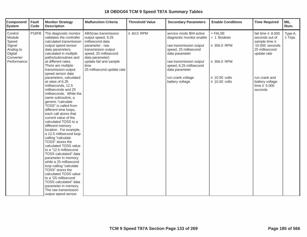
Component/System
FaultCode
Monitor StrategyDescription
Malfunction Criteria Threshold Value Secondary Parameters Enable Conditions Time Required MILIllum.
ControlModuleSpeedSignalAnalog toDigitalConverterPerformance
P16FB The diagnostic monitorvalidates the controllercalculated transmissionoutput speed sensordata parameters,calculated in multiplepaths/subroutines andat different rates.There are multipletransmission outputspeed sensor dataparameters, calculatedat rates of 6.25milliseconds, 12.5milliseconds and 25milliseconds. While thesame subroutine, ageneric “calculateTOSS” is called fromdifferent time loops,each call stores thatcurrent value of thecalculated TOSS to adifferent memorylocation. For example,a 12.5 millisecond loopcalling “calculateTOSS” stores thecalculated TOSS valueto a “12.5 millisecondTOSS calculated” dataparameter in memory,while a 25 millisecondloop calling “calculateTOSS” stores thecalculated TOSS valueto a “25 millisecondTOSS calculated” dataparameter in memory.The raw transmissionoutput speed sensor
ABS(raw transmissionoutput speed, 6.25millisecond dataparameter - rawtransmission outputspeed, 25 milliseconddata parameter)update fail and sampletime25 millisecond update rate
RPM60.0 service mode $04 activediagnsotic monitor enable
raw transmission outputspeed, 25 milliseconddata parameter
raw transmission outputspeed, 6.25 milliseconddata parameter
run crank voltagebattery voltage
= FALSE= Boolean1
RPM356.0
RPM356.0
volts10.00volts10.00
fail time 8.000seconds out ofsample time
seconds10.00025 millisecondupdate rate
run crank andbattery voltagetime 5.000seconds
Type A,1 Trips
18 OBDG04 TCM 9 Speed T87A Summary Tables
TCM 9 Speed T87A Section Page 133 of 269 Page 185 of 566

Component/System
FaultCode
Monitor StrategyDescription
Malfunction Criteria Threshold Value Secondary Parameters Enable Conditions Time Required MILIllum.
signal is diagnosedindependentlyelectrically and forperformance of thisDTC. The transmissionoutput speed sensordata parameters thatare calculated atdifferent rates mustalways be within anegligible difference ofeach other.
18 OBDG04 TCM 9 Speed T87A Summary Tables
TCM 9 Speed T87A Section Page 134 of 269 Page 186 of 566

Component/System
FaultCode
Monitor StrategyDescription
Malfunction Criteria Threshold Value Secondary Parameters Enable Conditions Time Required MILIllum.
Transmission SurgeAccumulatorSystemPerformance
P171D Detects when the surgeaccumulator system,used to providetransmission hydraulicpressure, is notcapable of supplyingadequate hydraulicpressure during anengine auto-start. Thetransmission holdingclutch pressures arecommanded to meetthe engine crank shafttorque output, toprevent clutch slip tothose holding clutches,during the engine auto-start. The diagnosticmonitors transmissioninput shaft speedduring the auto-startevent as the primarymalfunction criteria.Measured input shaftspeed that is excessiveis an indication theholding clutches areslipping due toinadequate hydraulicpressure, as a result ofa failed surgeaccumulator system.
Transmission turbinespeed is greater thanpredicted turbine speedduring autostart event,update initial fail count
P171D predictedturbine speed error
Refer to "TransmissionSupporting Tables" fordetails
PRNDL state defaulted
Transmission shift leverposition
Propulsion system active
Ignition voltageIgnition voltage
Transmission fluid tempTransmission fluid temp
Hybrid stateAutoStop duration min
During autostop Enginespeed was
****************************If above conditions aremet then the followingmust occur:
Turbine speed
Engine speed
Hydraulic pressure delaytime
If above conditions aremet then increment time-out timer.Time-out timer
Note: The initial fail
= False
= Forward range A
= True
> volts9.00< volts31.99
> °C0.00< °C110.00
= Engine offseconds1.200
< RPM5.0
RPM80.0
RPM450.0
P171D hydraulicpressure delay
Refer to "TransmissionSupporting Tables" fordetails
seconds0.38
counts12(initial fail count)Frequency=12.5ms
Once the abovecounts areachieved thenincrement thefinal fail counteronce. The finalfail counter canonly incrementonce perautostart event
counts (final3fail counter)
If above counteris greater thanthreshold thenreport DTCfailed.
Frequency =12.5ms
Type B,2 Trips
18 OBDG04 TCM 9 Speed T87A Summary Tables
TCM 9 Speed T87A Section Page 135 of 269 Page 187 of 566

Component/System
FaultCode
Monitor StrategyDescription
Malfunction Criteria Threshold Value Secondary Parameters Enable Conditions Time Required MILIllum.
counter must achieve it'sfail threshold in less thanthe time-out time.
*****************************If vehicle is launchedthen:
Transmission gear ratio
Trans 1st gear ratio
Trans 1st gear ratio
Trans gear ratio not 1stgearTrans gear ratio not 1stgear
Valid transmission gearratio achieved time
OR
If vehicle is not launchedbut autostart occurs then:
Turbine speed
Turbine speed less thenabove threshold for
Note: During an autostartevent the lack of hydraulicpressure will result inmomentary clutch slip in
= 1st gear ratio4.689= 2nd gear ratio3.306= 3rd gear ratio3.012= 4th gear ratio2.446= 5th gear ratio1.923= 6th gear ratio1.446
% of 1st gear1.120ratio
% of 1st gear0.880ratio
% of gear ratio1.070
% of gear ratio0.930
seconds0.500
RPM5.00
seconds0.500
18 OBDG04 TCM 9 Speed T87A Summary Tables
TCM 9 Speed T87A Section Page 136 of 269 Page 188 of 566

Component/System
FaultCode
Monitor StrategyDescription
Malfunction Criteria Threshold Value Secondary Parameters Enable Conditions Time Required MILIllum.
the C1234 clutch. Afterthe clutch slip event, themain transmission pumpand clutch will gaincapacity, clutch slip will goto zero. If the vehicle islaunching (moving) then avalid transmission ratiocan be achieved. Or if thebrake is continuallyapplied and an autostartoccurs naturally, then noratio can be measured. Inthis case turbine speedwill return to near zerorpm.*****************************
DTCs not fault active CrankSensor_FATransmission OutputShaft Angular VelocityValidityTransmission TurbineAngular Velocity ValidityTransmission OilTemperature ValidityP171AP171BP171CU0101P182EP1915
18 OBDG04 TCM 9 Speed T87A Summary Tables
TCM 9 Speed T87A Section Page 137 of 269 Page 189 of 566

Component/System
FaultCode
Monitor StrategyDescription
Malfunction Criteria Threshold Value Secondary Parameters Enable Conditions Time Required MILIllum.
AccelerationSensorSignalMessageCounterIncorrect
P175F The diagnostic monitordetects an alive rollingcount error orchecksum error in theCAN frame containingthe lateral accelerationsignal value andlongitudinalacceleration sensorsignal value.
rolling count valuereceived from EBCM andexpected TCM calculatedvalue not equalORchecksum lateral andlongitudinal accelerationCAN frame messagevalue error
50 millisecond update rate
= TRUE
= TRUE
enable alive rolling counterror detection:diagnostic monitor enablelateral and longitudinalacceleration CAN framemessage receivedbattery voltagerun crank voltage
enable checksum errordetection:diagnostic monitor enablelateral and longitudinalacceleration CAN framemessage receivednormal CANbattery voltagerun crank voltagecommunication enabled
DTCs not fault active
= Boolean1= TRUE
volts11.0volts11.0
= Boolean1= TRUE
volts11.0volts11.0
= TRUE
U0073
alive rollingcount errors 54out of sample9counts50 millisecondupdate rate
checksum errortime 54.00seconds
SpecialType C
18 OBDG04 TCM 9 Speed T87A Summary Tables
TCM 9 Speed T87A Section Page 138 of 269 Page 190 of 566

Component/System
FaultCode
Monitor StrategyDescription
Malfunction Criteria Threshold Value Secondary Parameters Enable Conditions Time Required MILIllum.
Up andDown ShiftSwitchSignalCircuit
P1761 The alive rolling countnormally cycles 0, 1, 2,and 3 as a serial dataperiodic frame isprocessed normally.The diagnostic monitorcounts the number oftimes an alive rollingcount error occurs overa period of time. TheTCM receives a serialdata frame at a periodicrate, during which, thereceive data isprocessed thecomparing the currentvalue of the alive rollingcount in the frame dateto the incrementedvalue of the diagnosticalive rolling count.When the two values ofthe alive rolling countdo not agree, an aliverolling count error hasoccurred. The errorindicator is saved in anarray buffer, and whenthe number of errorindicators in the bufferexceed the failthreshold the fail time isallowed to time up.
alive rolling count errorcounterupdate fail time100 millisecond updaterate
counts3 service mode $04 activediagnostic monitor enable
run crank voltage
up and down shift serialdata frame receiveoccurred
when up and down shiftserial data frame receiveoccurred:increment the diagnsoticalive rolling count datavalue,if the diagnsotic aliverolling count data value,set alive rolling counterror to TRUE,
when alive rolling counterror ANDprevious alive rollingcount error in 10 elementarrary buffer,increment alive rollingcount error counter
= FALSE= Boolean1
volts9.00
= TRUE
frame alive rolling countdata value
= TRUE
= FALSE
fail time 10.00seconds
run crank voltagetime 0.100seconds
SpecialType C
18 OBDG04 TCM 9 Speed T87A Summary Tables
TCM 9 Speed T87A Section Page 139 of 269 Page 191 of 566

Component/System
FaultCode
Monitor StrategyDescription
Malfunction Criteria Threshold Value Secondary Parameters Enable Conditions Time Required MILIllum.
switch stateupdate fail time 1100 millisecond updaterate
= tap up (upshift) stateactive
service mode $04 activediagnostic monitor enable
run crank voltage
run crank voltageP1761 fault activeP1767 fault activeP1767 test fail this key onP1767 fault pending(P1765 fault active ORP1765 fault active test failthis key on)PRNDL range changetimePRNDL in range:D1 ORD2 ORD3 ORD4 ORD5 ORD6 ORD7 ORD8 ORD9 ORD10 ORNEUTRAL ORPARK ORREVERSE
DTCs not fault pending
= FALSE= Boolean0
volts5.00
volts9.00= FALSE= FALSE= FALSE= FALSE= FALSE= FALSE
= Boolean1= Boolean1= Boolean1= Boolean1= Boolean1= Boolean1= Boolean1= Boolean1= Boolean1= Boolean0= Boolean0= Boolean0= Boolean0
Transmission Shift LeverPosition Validity
fail time 1 1.00seconds
run crank voltagetime 25milliseconds
seconds1.00
UpshiftSwitchCircuit 2
P1765 Diagnoses the state ofthe upshift switchcircuit, stuck in thestate "tap up" (upshift)active.
SpecialType C
switch stateupdate fail time 2100 millisecond updaterate
= tap up (upshift) stateactive
service mode $04 activediagnostic monitor enable
run crank voltage
run crank voltageP1761 fault activeP1767 fault activeP1767 test fail this key on
= FALSE= Boolean0
volts5.00
volts9.00= FALSE= FALSE= FALSE
fail time 2 seconds120.00
run crank voltagetime 25milliseconds
18 OBDG04 TCM 9 Speed T87A Summary Tables
TCM 9 Speed T87A Section Page 140 of 269 Page 192 of 566

Component/System
FaultCode
Monitor StrategyDescription
Malfunction Criteria Threshold Value Secondary Parameters Enable Conditions Time Required MILIllum.
P1767 fault pending(P1765 fault active ORP1765 fault active test failthis key on)PRNDL range changetimePRNDL in range:D1 ORD2 ORD3 ORD4 ORD5 ORD6 ORD7 ORD8 ORD9 ORD10 ORNEUTRAL ORPARK ORREVERSE
DTCs not fault pending
= FALSE= FALSE= FALSE
= Boolean1= Boolean1= Boolean1= Boolean1= Boolean1= Boolean1= Boolean1= Boolean1= Boolean1= Boolean0= Boolean0= Boolean0= Boolean0
Transmission Shift LeverPosition Validity
seconds1.00
18 OBDG04 TCM 9 Speed T87A Summary Tables
TCM 9 Speed T87A Section Page 141 of 269 Page 193 of 566
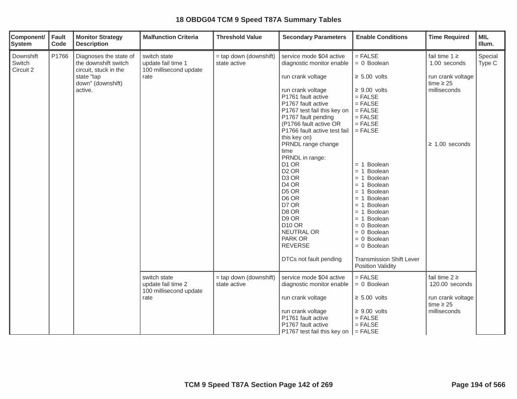
Component/System
FaultCode
Monitor StrategyDescription
Malfunction Criteria Threshold Value Secondary Parameters Enable Conditions Time Required MILIllum.
switch stateupdate fail time 1100 millisecond updaterate
= tap down (downshift)state active
service mode $04 activediagnostic monitor enable
run crank voltage
run crank voltageP1761 fault activeP1767 fault activeP1767 test fail this key onP1767 fault pending(P1766 fault active ORP1766 fault active test failthis key on)PRNDL range changetimePRNDL in range:D1 ORD2 ORD3 ORD4 ORD5 ORD6 ORD7 ORD8 ORD9 ORD10 ORNEUTRAL ORPARK ORREVERSE
DTCs not fault pending
= FALSE= Boolean0
volts5.00
volts9.00= FALSE= FALSE= FALSE= FALSE= FALSE= FALSE
= Boolean1= Boolean1= Boolean1= Boolean1= Boolean1= Boolean1= Boolean1= Boolean1= Boolean1= Boolean0= Boolean0= Boolean0= Boolean0
Transmission Shift LeverPosition Validity
fail time 1 seconds1.00
run crank voltagetime 25milliseconds
seconds1.00
DownshiftSwitchCircuit 2
P1766 Diagnoses the state ofthe downshift switchcircuit, stuck in thestate "tapdown" (downshift)active.
SpecialType C
switch stateupdate fail time 2100 millisecond updaterate
= tap down (downshift)state active
service mode $04 activediagnostic monitor enable
run crank voltage
run crank voltageP1761 fault activeP1767 fault activeP1767 test fail this key on
= FALSE= Boolean0
volts5.00
volts9.00= FALSE= FALSE= FALSE
fail time 2 seconds120.00
run crank voltagetime 25milliseconds
18 OBDG04 TCM 9 Speed T87A Summary Tables
TCM 9 Speed T87A Section Page 142 of 269 Page 194 of 566

Component/System
FaultCode
Monitor StrategyDescription
Malfunction Criteria Threshold Value Secondary Parameters Enable Conditions Time Required MILIllum.
P1767 fault pending(P1766 fault active ORP1766 fault active test failthis key on)PRNDL range changetimePRNDL in range:D1 ORD2 ORD3 ORD4 ORD5 ORD6 ORD7 ORD8 ORD9 ORD10 ORNEUTRAL ORPARK ORREVERSE
DTCs not fault pending
= FALSE= FALSE= FALSE
= Boolean1= Boolean1= Boolean1= Boolean1= Boolean1= Boolean1= Boolean1= Boolean1= Boolean1= Boolean0= Boolean0= Boolean0= Boolean0
Transmission Shift LeverPosition Validity
seconds1.00
18 OBDG04 TCM 9 Speed T87A Summary Tables
TCM 9 Speed T87A Section Page 143 of 269 Page 195 of 566

Component/System
FaultCode
Monitor StrategyDescription
Malfunction Criteria Threshold Value Secondary Parameters Enable Conditions Time Required MILIllum.
Up andDown ShiftSwitchCircuit 2
P1767 Diagnoses the state ofthe upshift/downshiftswitch circuit at anillegal voltage, voltageout of range.
switch stateupdate fail time100 millisecond updaterate
= illegal (voltage out ofrange)
service mode $04 activediagnostic monitor enable
run crank voltagerun crank voltage time
run crank voltageP1761 fault activeP1767 fault active
= FALSE= Boolean0
volts5.00 25 milliseconds
volts9.00= FALSE= FALSE
fail time 60.00seconds
SpecialType C
18 OBDG04 TCM 9 Speed T87A Summary Tables
TCM 9 Speed T87A Section Page 144 of 269 Page 196 of 566

Component/System
FaultCode
Monitor StrategyDescription
Malfunction Criteria Threshold Value Secondary Parameters Enable Conditions Time Required MILIllum.
Transmission PlanetaryGearsetRing GearSpeedSensorCircuitRange/Performance
P176B The diagnostic monitorrationalizes thetransmissionintermediate shaftspeed sensor by usingthe transmission outputshaft output speedsensor and the knownratio between thetransmissionintermediate shaftspeed and thetransmission outputshaft output speedbased on thecommanded gear andthe transmission levernode design. Theestimated transmissionintermediate shaftspeed is equal to thegear ratio times thetransmission outputshaft output speed.The absolute value ofthe delta between themeasured transmissionintermediate shaftspeed and theestimated transmissionintermediate shaftspeed is used todetermine if themeasured transmissionintermediate shaftspeed is rational.
delta1 = ABS(transmission input speed- (transmission outputspeed * gear ratiocommanded))ANDdelta2 = ABS(transmission input speed- (transmissionintermediate speed * ratiocalibration))
update faiil time25 millisecond update rate
> RPM10.0
>
P176B intermediatespeed sensor failRPM threshold
see supporting tables
diagnostic monitor enable
speed sesnorconfiguration calibration issingle OR dual
ratio calibration is functionof command gear andintermediate speedsesnor when notREVERSE
ratio calibration is functionof command gear andintermediate speedsesnor when REVERSE
******************************delay time updates when:estimated transmissionintermediate speed(transmission input
= Boolean1
=CeTNSR_e_NSPD_SingleSpdSnsr
=P176B ratio calibrationwhen not REVERSE
see supporting tables
=P176B ratio calibrationwhen REVERSE
see supporting tables
******************************
P176B minimumestimated transmissionintermediate speed toenable fail evaluation
fail time P176Bintermediatespeed sensorfail timethresholdsee supportingtables
fail timethreshold metincrements failcount,fail count P176Bintermediatespeed sensorfail countthresholdsee supportingtables
*******************delay time
Type A,1 Trips
18 OBDG04 TCM 9 Speed T87A Summary Tables
TCM 9 Speed T87A Section Page 145 of 269 Page 197 of 566

Component/System
FaultCode
Monitor StrategyDescription
Malfunction Criteria Threshold Value Secondary Parameters Enable Conditions Time Required MILIllum.
speed / ratio calibration)with
transmission input speed
input speed sensor readybased on commaned gearand transmissionintermediate speedsensor (state output mustbe FALSE to enable failevaluation)withwith attained gear
*****************************transmission input speedtransmission output speedneutral idle moderange shift stateP0716 fault activeP0717 fault activeP07BF fault activeP07C0 fault activeP0722 fault activeP0723 fault activeP077C fault activeP077D fault activeP176C fault activeP176D fault activebattery voltage
see supporting tables
P176B minimumtransmission inputspeed to enable failevaluation
see supporting tables
=P176B holding clutchstates
see supporting tables
= REVERSEOR= 1st thru 10th
******************************RPM172.0
RPM89.0= nuetral idle mode ON= range shift complete= FALSE= FALSE= FALSE= FALSE= FALSE= FALSE= FALSE= FALSE= FALSE= FALSE
volts9.00
= FALSE
P176B delay toallowtransmissioninput,intermediateand outputspeeds tostablize for failevaluationsee supportingtables
18 OBDG04 TCM 9 Speed T87A Summary Tables
TCM 9 Speed T87A Section Page 146 of 269 Page 198 of 566

Component/System
FaultCode
Monitor StrategyDescription
Malfunction Criteria Threshold Value Secondary Parameters Enable Conditions Time Required MILIllum.
service fast learn activerun crank voltage
transmission hydraulicpressure available:engine speed
volts9.00
RPM400
battery voltagetime 0.100seconds
run crank voltagetime 0.100seconds
engine speedtime engine speedtime fortransmissionhydraulicpressureavailablesee supportingtables
18 OBDG04 TCM 9 Speed T87A Summary Tables
TCM 9 Speed T87A Section Page 147 of 269 Page 199 of 566

Component/System
FaultCode
Monitor StrategyDescription
Malfunction Criteria Threshold Value Secondary Parameters Enable Conditions Time Required MILIllum.
Transmission PlanetaryGearsetRing GearSpeedSensorCircuit Low
P176C Controller specificanalog circuitdiagnoses thetransmissionintermediate speedsensor and wiring for ashort to ground fault bycomparing a voltagemeasurement tocontroller specificvoltage thresholds.
transmission intermediatespeed sesnor raw voltage,update fail time,12.5 millisecond updaterate
volts0.2500 0.5 impedance
between signal andcontroller ground) service mode $04 active
diagnostic monitor enableP176D fault activeservice fast learn
run crank voltagebattery voltage
P176C fault activeP176C test fail this key on
= FALSE= Boolean1= FALSE= FALSE
volts10.00volts10.00
= FALSE= FALSE
fail time 0.050seconds, updatefail count12.5 millisecondupdate rate
fail count 40counts12.5 millisecondupdate rate
run crank andbattery voltagetime 5.000seconds
Type A,1 Trips
18 OBDG04 TCM 9 Speed T87A Summary Tables
TCM 9 Speed T87A Section Page 148 of 269 Page 200 of 566

Component/System
FaultCode
Monitor StrategyDescription
Malfunction Criteria Threshold Value Secondary Parameters Enable Conditions Time Required MILIllum.
Transmission PlanetaryGearsetRing GearSpeedSensorCircuit High
P176D Controller specificanalog circuitdiagnoses thetransmissionintermediate speedsensor and wiring for ashort to voltage fault bycomparing a voltagemeasurement tocontroller specificvoltage thresholds.
transmission intermediatespeed sesnor raw voltage,update fail time,12.5 millisecond updaterate
volts4.7500 0.5 impedance
between signal andcontroller power) service mode $04 active
diagnostic monitor enableP176C fault activeservice fast learn
run crank voltagebattery voltage
P176D fault activeP176D test fail this key on
= FALSE= Boolean1= FALSE= FALSE
volts10.00volts10.00
= FALSE= FALSE
fail time 0.050seconds, updatefail count12.5 millisecondupdate rate
fail count 40counts12.5 millisecondupdate rate
run crank andbattery voltagetime 5.000seconds
Type A,1 Trips
18 OBDG04 TCM 9 Speed T87A Summary Tables
TCM 9 Speed T87A Section Page 149 of 269 Page 201 of 566

Component/System
FaultCode
Monitor StrategyDescription
Malfunction Criteria Threshold Value Secondary Parameters Enable Conditions Time Required MILIllum.
IntermediateSpeedSensor 1DirectionError
P17D3 The diagnostic monitordetermines if thedirection transmissionintermediate speedsensor value iscoherent based on theon period time of thedirectional sensor andraw speed sensorvalue. When the onperiod time indicates atransitional state, thedirection must also betransitional asmeasured by very slowraw signal RPM. Whenthe on period timeindicates a non-transitional state,forward or reverse, thedirection must also betransition, not forwardand not reverse.
intermediate speedsesnor raw directionwhen transitional period =FALSEANDintermediate speedsesnor raw directionwhen transitional period =FALSEORintermediate speedsesnor rawwhen transitional period =TRUE
update fail and sampletime6.26 millisecond updaterate
FORWARD
REVERSE
P17C5 P17D3intermediate speedsensor RPM
service mode $04 activediagnostic monitor enableintermediate speedsesnor count sampleperiodP17D3 fault active ORP17D3 test fail this key onsenor type cailbration(senor type is directional)
transitional perioddetected = FALSE when:on period ORon periodwhen direction unknownORon periodon periodwhen direction is reverseORon periodon periodwhen direction is forward
transitional perioddetected = TRUE when:on periodon periodwhen direction unknown
= FALSE= Boolean1 0 counts
= FALSE= FALSE=CeTNSR_e_NSPD_SingleSpdSnsr
seconds0.4434seconds0.2773
< seconds0.2363> seconds0.1240
< seconds0.0811> seconds0.0088
< seconds0.4434> seconds0.2773
fail time 3.500secondsout of sampletime 5.000seconds
Type A,1 Trips
18 OBDG04 TCM 9 Speed T87A Summary Tables
TCM 9 Speed T87A Section Page 150 of 269 Page 202 of 566

Component/System
FaultCode
Monitor StrategyDescription
Malfunction Criteria Threshold Value Secondary Parameters Enable Conditions Time Required MILIllum.
Transmission Park ValvePositionSensor/Switch ACircuit/Open
P17F5 The diagnostic monitordetects an illegalvoltage on the parkvalve position sensorcircuit.
raw sensor voltageraw sensor voltage
> volts1.263< volts1.504
diagnostic monitor enablebattery voltagebattery voltage timeETRS systemconfiguration is internalERTSpark sensor configurationtype is hall sensor
= Boolean1volts9.00seconds1.00
=CeTRGR_e_InternalETRS
= CePSCR_e_HallSns
seconds0.100in second0.163sample
6.25 millisecondupdate rate
Type A,1 Trips
18 OBDG04 TCM 9 Speed T87A Summary Tables
TCM 9 Speed T87A Section Page 151 of 269 Page 203 of 566

Component/System
FaultCode
Monitor StrategyDescription
Malfunction Criteria Threshold Value Secondary Parameters Enable Conditions Time Required MILIllum.
raw sensor voltage < volts0.414 diagnostic monitor enablebattery voltagebattery voltage timeETRS systemconfiguration is internalERTSpark sensor configurationtype is hall sensor
Boolean1volts9.00seconds1.00
=CeTRGR_e_InternalETRS
= CePSCR_e_HallSns
seconds0.100in second0.163sample
6.25 millisecondupdate rate
Transmission Park ValvePositionSensor/Switch ACircuit Low
P17F6 The diagnostic monitordetects a ground shortor open circuit fault inthe park valve positionsensor circuit.
Type A,1 Trips
sensor voltage directproportion
raw sensor % duty cycle
sensor voltage indirectproportion
raw sensor % duty cycle
=CePSCD_e_VoltDirctProp
% duty cycle9.998
=CePSCD_e_VoltDirctProp
% duty cycle9.998
diagnostic monitor enablebattery voltagebattery voltage timeETRS systemconfiguration is internalERTSpark sensor configurationtype is PWM sensor
= Boolean1volts9.00seconds1.00
=CeTRGR_e_InternalETRS
= CePSCR_e_HallSns
seconds1.000in second1.500sample
6.25 millisecondupdate rate
18 OBDG04 TCM 9 Speed T87A Summary Tables
TCM 9 Speed T87A Section Page 152 of 269 Page 204 of 566

Component/System
FaultCode
Monitor StrategyDescription
Malfunction Criteria Threshold Value Secondary Parameters Enable Conditions Time Required MILIllum.
raw sensor voltage > volts2.538 diagnostic monitor enablebattery voltagebattery voltage timeETRS systemconfiguration is internalERTSpark sensor configurationtype is hall sensor
= Boolean1volts9.00seconds1.00
=CeTRGR_e_InternalETRS
= CePSCR_e_HallSns
seconds0.100in second0.163sample
6.25 millisecondupdate rate
Transmission Park ValvePositionSensor/Switch ACircuit High
P17F7 The diagnostic monitordetects a short tovoltage circuit fault inthe park valve positionsensor circuit.
Type A,1 Trips
sensor voltage directproportion
raw sensor % duty cycle
sensor voltage indirectproportion
raw sensor % duty cycle
=CePSCD_e_VoltDirctProp
% duty cycle91.998
=CePSCD_e_VoltDirctProp
% duty cycle91.998
diagnostic monitor enablebattery voltagebattery voltage timeETRS systemconfiguration is internalERTSpark sensor configurationtype is PWMsensor
= Boolean1volts9.00seconds1.00
=CeTRGR_e_InternalETRS
= CePSCR_e_HallSns
seconds1.000in second1.500sample
6.25 millisecondupdate rate
18 OBDG04 TCM 9 Speed T87A Summary Tables
TCM 9 Speed T87A Section Page 153 of 269 Page 205 of 566

Component/System
FaultCode
Monitor StrategyDescription
Malfunction Criteria Threshold Value Secondary Parameters Enable Conditions Time Required MILIllum.
Transmission Park ValvePositionSensor/Switch BCircuit/Open
P17FA The diagnostic monitordetects an illegalvoltage on the parkvalve position sensorcircuit.
raw sensor voltageraw sensor voltage
> volts1.263< volts1.504
diagnostic monitor enablebattery voltagebattery voltage timeETRS systemconfiguration is internalERTSpark sensor configurationtype is hall sensor
= Boolean1volts9.00seconds1.00
=CeTRGR_e_InternalETRS
= CePSCR_e_HallSns
seconds0.100in second0.163sample
6.25 millisecondupdate rate
Type A,1 Trips
18 OBDG04 TCM 9 Speed T87A Summary Tables
TCM 9 Speed T87A Section Page 154 of 269 Page 206 of 566

Component/System
FaultCode
Monitor StrategyDescription
Malfunction Criteria Threshold Value Secondary Parameters Enable Conditions Time Required MILIllum.
raw sensor voltage < volts0.414 diagnostic monitor enablebattery voltagebattey voltage timeETRS systemconfiguration is internalERTSpark sensor configurationtype is hall sensor
= Boolean1volts9.00seconds1.00
=CeTRGR_e_InternalETRS
= CePSCR_e_HallSns
seconds0.100in second0.163sample
6.25 millisecondupdate rate
Transmission Park ValvePositionSensor/Switch BCircuit Low
P17FB The diagnostic monitordetects a ground shortor open circuit fault inthe park valve positionsensor circuit.
Type A,1 Trips
sensor voltage directproportion
raw sensor % duty cycle
sensor voltage indirectproportion
raw sensor % duty cycle
=CePSCD_e_VoltDirctProp
% duty cycle9.998
=CePSCD_e_VoltDirctProp
% duty cycle9.998
diagnostic monitor enablebattery voltagebattery voltage timeETRS systemconfiguration is internalERTSpark sensor configurationtype is PWM sensor
= Boolean1volts9.00seconds1.00
=CeTRGR_e_InternalETRS
= CePSCR_e_HallSns
seconds1.000in second1.500sample
6.25 millisecondupdate rate
18 OBDG04 TCM 9 Speed T87A Summary Tables
TCM 9 Speed T87A Section Page 155 of 269 Page 207 of 566

Component/System
FaultCode
Monitor StrategyDescription
Malfunction Criteria Threshold Value Secondary Parameters Enable Conditions Time Required MILIllum.
raw sensor voltage > volts2.538 diagnostic monitor enablebattery voltagebattery voltage timeETRS systemconfiguration is internalERTSpark sensor configurationtype is hall sensor
= Boolean1volts9.00seconds1.00
=CeTRGR_e_InternalETRS
= CePSCR_e_HallSns
seconds0.100in second0.163sample
6.25 millisecondupdate rate
Transmission Park ValvePositionSensor/Switch BCircuit High
P17FC The diagnostic monitordetects a short tovoltage circuit fault inthe park valve positionsensor circuit.
Type A,1 Trips
sensor voltage directproportion
raw sensor % duty cycle
sensor voltage indirectproportion
raw sensor % duty cycle
=CePSCD_e_VoltDirctProp
% duty cycle91.998
=CePSCD_e_VoltDirctProp
% duty cycle91.998
diagnostic monitor enablebattery voltagebattery voltage timeETRS systemconfiguration is internalERTSpark sensor configurationtype is PWMsensor
= Boolean1volts9.00seconds1.00
=CeTRGR_e_InternalETRS
= CePSCR_e_HallSns
seconds1.000in second1.500sample
6.25 millisecondupdate rate
18 OBDG04 TCM 9 Speed T87A Summary Tables
TCM 9 Speed T87A Section Page 156 of 269 Page 208 of 566

Component/System
FaultCode
Monitor StrategyDescription
Malfunction Criteria Threshold Value Secondary Parameters Enable Conditions Time Required MILIllum.
Up andDown ShiftSwitchPerformance
P1876 This diagnostic monitorrationalizes thePRNDL, transmissionshift lever position,against the state for thetap-up-tap-down(TUTD) enable switchor the manual-up-manual-down (MUMD)enable switch. Theswitch circuit isconsidered failing whenthe PRNDL is in park,reverse or neutral, andthe switch circuit isindicating the switch inin the enable, or TUTD/MUMD function requeststate. The switch canonly be in the enablestate when the PRNDLis in the appropriatedrive range, forexample D9, D8 or D7,but not in park, reverseor neutral.
(PRNDLORPRNDLORPRNDL)
AND
(shift lever rangecalibration is tap-up-tap-down (TUTD)ORshift lever rangecalibration is manual-up-manual-down (MUMD))
AND
TUTD/MUMD enablerequest (switch state)
update fail time
100 millisecond updaterate
= NEUTRAL
= REVERSE
= PARK
=CeTUDR_e_TUTD_ModeOnly
= TRUE
service mode $04 activediagnostic monitor enable(P1876 test fail this keyon ORP1876 fault active)
PRNDLORPRNDLORPRNDL
DTCs not test fail this keyon
DTCs not fault active
= FALSE= Boolean0= FALSE
= FALSE
= NEUTRAL
= REVERSE
= PARK
P0815, P0816, P0826
Transmission Shift LeverPosition ValidityU0100, P0815, P0816,P0826, P1761, P0707,P0708
fail time 3.00seconds, updatefail count
fail count 5counts
100 millisecondupdate rate
SpecialType C
18 OBDG04 TCM 9 Speed T87A Summary Tables
TCM 9 Speed T87A Section Page 157 of 269 Page 209 of 566

Component/System
FaultCode
Monitor StrategyDescription
Malfunction Criteria Threshold Value Secondary Parameters Enable Conditions Time Required MILIllum.
Transmission Park ValveStuck On
P187D This diagnostic monitorrationalizes the driverETRS commanddirection of “out ofPARK” against theactual park valveposition, as the parkvalve position ismeasured by the parkvalve position sensor Aor B.
when:(Park Valve PositionSensor A ORPark Valve PositionSensor B) AND(out of park statecalculated ORout of park statecalculated)update delay time
when:delay time
increment fail count
= PARK
= PARK
= UNKNOWN
= PARK
KtPSDR_t_ParkVlvStkOn_DlyLim
park servo enableETRS system type isinternal ETRSbattery voltagefor battery voltage timediagnostic monitor enable
park state transtion isTRUE when:(out of park statecalculated ORout of park statecalculated) ANDP187D, P187E Test FailThis Key OnAND((ETRS commanddirection ANDout of park state)OR(ETRS commanddirection ANDout of park state))otherwise park statetransition is FALSE
park state transition AND(P17F5, P17F6, P17F7Fault Active ORP17FA, P17FB, P17FCFault Active) ANDP187D, P187E FaultActive
park servo stuck onavailabe is TRUE when:ETRS command direction((ETRS commanddirection ANDP18AB Test Fail This KeyOn) OR
= Boolean1=CeTRGR_e_InternalETRS
volts9.00seconds1.000
= Boolean1
= PARK
= OUT OF PARK
= FALSE
= PARK
PARK
PARK
OUT OF PARK
= TRUE= FALSE
= FALSE
= FALSE
PARK= DRIVE
fail count 2counts
update rate 6.25milliseconds
Type A,1 Trips
18 OBDG04 TCM 9 Speed T87A Summary Tables
TCM 9 Speed T87A Section Page 158 of 269 Page 210 of 566
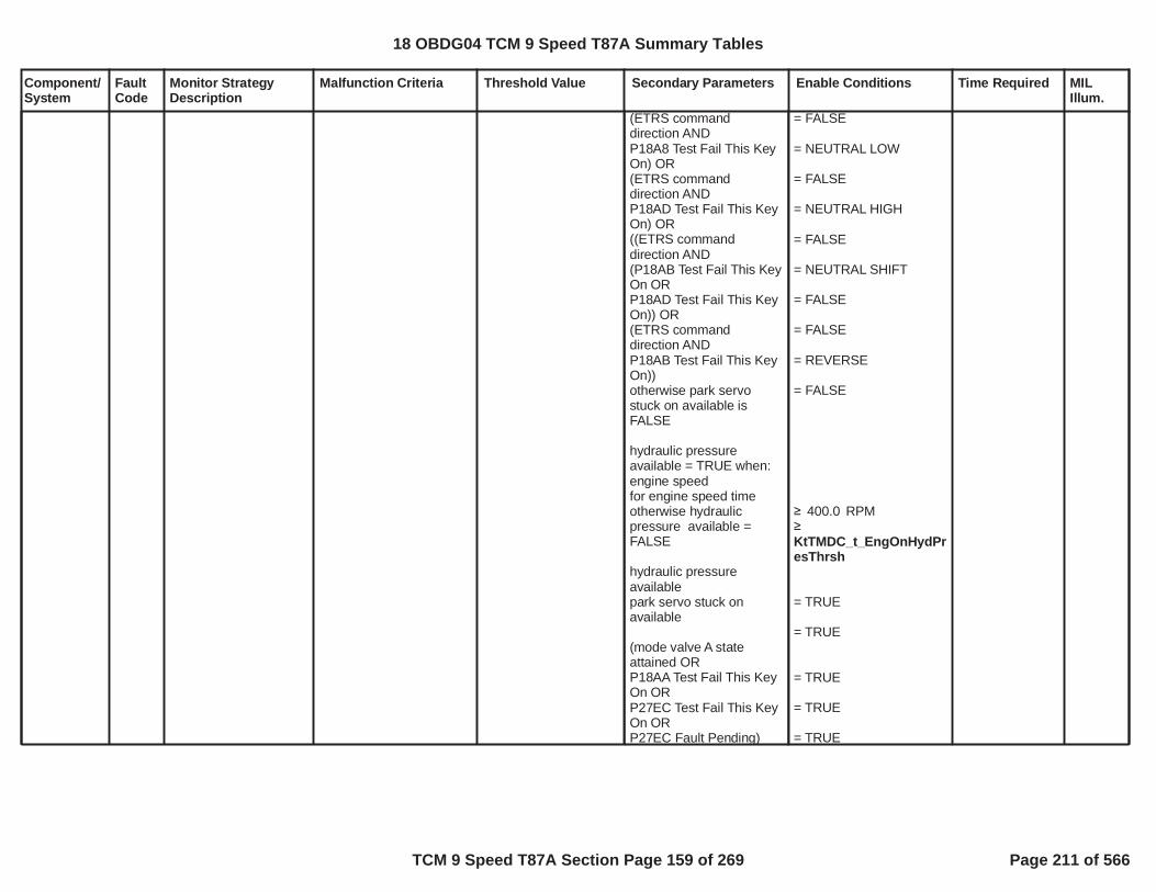
Component/System
FaultCode
Monitor StrategyDescription
Malfunction Criteria Threshold Value Secondary Parameters Enable Conditions Time Required MILIllum.
(ETRS commanddirection ANDP18A8 Test Fail This KeyOn) OR(ETRS commanddirection ANDP18AD Test Fail This KeyOn) OR((ETRS commanddirection AND(P18AB Test Fail This KeyOn ORP18AD Test Fail This KeyOn)) OR(ETRS commanddirection ANDP18AB Test Fail This KeyOn))otherwise park servostuck on available isFALSE
hydraulic pressureavailable = TRUE when:engine speedfor engine speed timeotherwise hydraulicpressure available =FALSE
hydraulic pressureavailablepark servo stuck onavailable
(mode valve A stateattained ORP18AA Test Fail This KeyOn ORP27EC Test Fail This KeyOn ORP27EC Fault Pending)
= FALSE
= NEUTRAL LOW
= FALSE
= NEUTRAL HIGH
= FALSE
= NEUTRAL SHIFT
= FALSE
= FALSE
= REVERSE
= FALSE
RPM400.0
KtTMDC_t_EngOnHydPresThrsh
= TRUE
= TRUE
= TRUE
= TRUE
= TRUE
18 OBDG04 TCM 9 Speed T87A Summary Tables
TCM 9 Speed T87A Section Page 159 of 269 Page 211 of 566

Component/System
FaultCode
Monitor StrategyDescription
Malfunction Criteria Threshold Value Secondary Parameters Enable Conditions Time Required MILIllum.
AND(mode valve B stateattained ORP18AC Test Fail This KeyOn ORP27F0 Test Fail This KeyOn ORP27F0 Fault Pending)
= TRUE
= TRUE
= TRUE
= TRUE
= TRUE
18 OBDG04 TCM 9 Speed T87A Summary Tables
TCM 9 Speed T87A Section Page 160 of 269 Page 212 of 566

Component/System
FaultCode
Monitor StrategyDescription
Malfunction Criteria Threshold Value Secondary Parameters Enable Conditions Time Required MILIllum.
when:ETRS command directionout of park statemode valve A positionmode valve B positionupdate delay time
when:delay time
increment fail time
= PARK PARK
= mode valve low= mode valve low
KtPSDR_t_ParkServo_EngOff_Lim
park servo enableETRS system type isinternal ETRSbattery voltagefor battery voltage timeengine mode run
hydraulic pressureavailable is TRUE when:engine speedfor engine speed timeotherwise hydraulicpressure available isFALSE
hydraulic pressureavailablesurge accumulator on/offrequestengine off diagnosticenabled
P187D, P187E Test FailThis Key On
= Boolean1=CeTRGR_e_InternalETRS
volts9.00seconds1.000
= FALSE
RPM400.0
KtTMDC_t_EngOnHydPresThrsh
= FALSE
= FALSE
= Boolean1
= FALSE
fail time KtPSDR_t_ParkServo_EngOff_Limseconds
update rate 6.25milliseconds
Transmission Park ValveStuck Off
P187E This diagnostic monitorrationalizes the driverETRS commanddirection of “PARK”against the actual parkvalve position, as thepark valve position ismeasured by the modevalve position sensor Aand B.
Type A,1 Trips
when:(Park Valve PositionSensor A ORPark Valve PositionSensor B) AND(out of park statecalculated ORout of park statecalculated)update delay time
when:delay time
= OUT OF PARK
= OUT OF PARK
= UNKNOWN
= OUT OF PARK
KtPSDR_t_ParkVlvStkOff_DlyLim
park servo enableETRS system type isinternal ETRSbattery voltagefor battery voltage timediagnsotic monitor enable
park state transtion isTRUE when:(out of park statecalculated ORout of park statecalculated) ANDP187D, P187E Test FailThis Key OnAND
= Boolean1=CeTRGR_e_InternalETRS
volts9.00seconds1.000
= Boolean1
= PARK
= OUT OF PARK
= FALSE
fail count 2counts
update rate 6.25milliseconds
18 OBDG04 TCM 9 Speed T87A Summary Tables
TCM 9 Speed T87A Section Page 161 of 269 Page 213 of 566
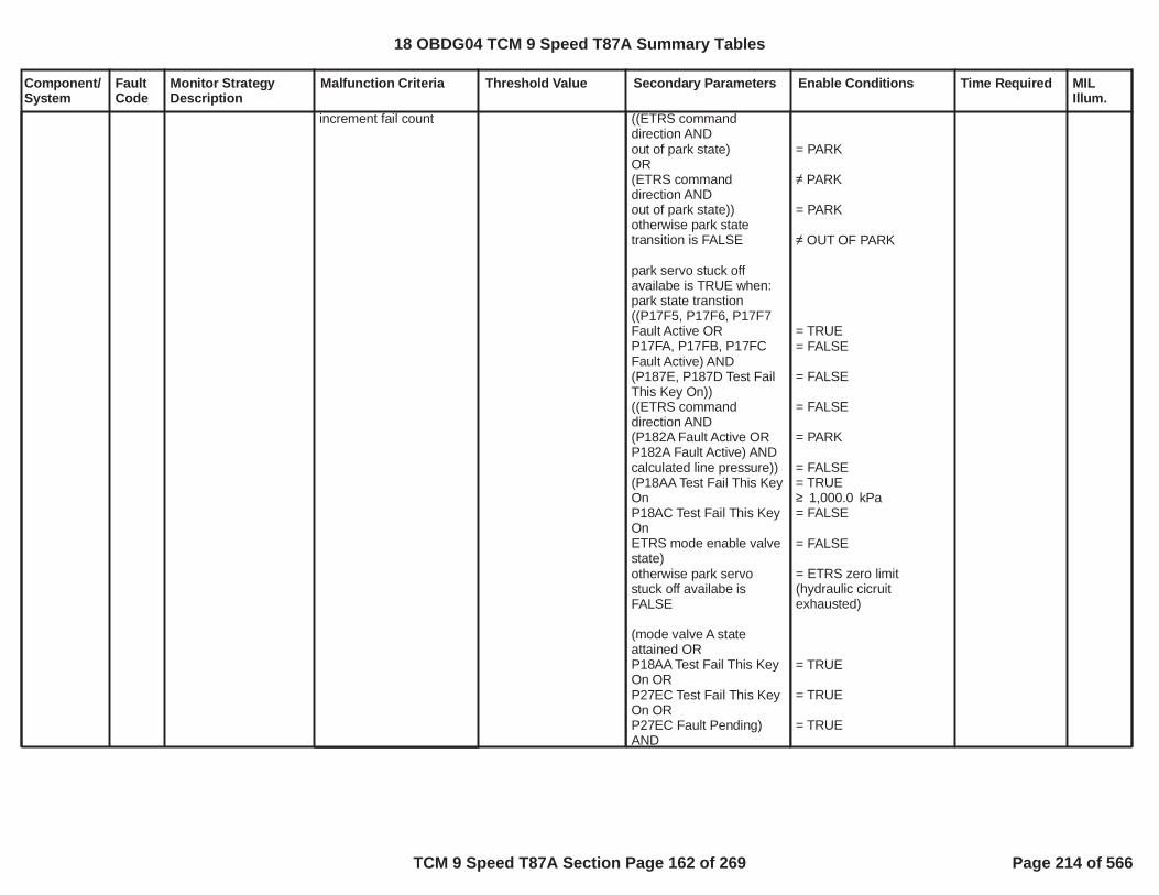
Component/System
FaultCode
Monitor StrategyDescription
Malfunction Criteria Threshold Value Secondary Parameters Enable Conditions Time Required MILIllum.
increment fail count ((ETRS commanddirection ANDout of park state)OR(ETRS commanddirection ANDout of park state))otherwise park statetransition is FALSE
park servo stuck offavailabe is TRUE when:park state transtion((P17F5, P17F6, P17F7Fault Active ORP17FA, P17FB, P17FCFault Active) AND(P187E, P187D Test FailThis Key On))((ETRS commanddirection AND(P182A Fault Active ORP182A Fault Active) ANDcalculated line pressure))(P18AA Test Fail This KeyOnP18AC Test Fail This KeyOnETRS mode enable valvestate)otherwise park servostuck off availabe isFALSE
(mode valve A stateattained ORP18AA Test Fail This KeyOn ORP27EC Test Fail This KeyOn ORP27EC Fault Pending)AND
= PARK
PARK
= PARK
OUT OF PARK
= TRUE= FALSE
= FALSE
= FALSE
= PARK
= FALSE= TRUE
kPa1,000.0= FALSE
= FALSE
= ETRS zero limit(hydraulic cicruitexhausted)
= TRUE
= TRUE
= TRUE
18 OBDG04 TCM 9 Speed T87A Summary Tables
TCM 9 Speed T87A Section Page 162 of 269 Page 214 of 566

Component/System
FaultCode
Monitor StrategyDescription
Malfunction Criteria Threshold Value Secondary Parameters Enable Conditions Time Required MILIllum.
(mode valve B stateattained ORP18AC Test Fail This KeyOn ORP27F0 Test Fail This KeyOn ORP27F0 Fault Pending ORETRS mode enable valvestate)
= TRUE
= TRUE
= TRUE
= TRUE
= TRUE= ETRS zero limit(hydraulic cicruitexhausted)
18 OBDG04 TCM 9 Speed T87A Summary Tables
TCM 9 Speed T87A Section Page 163 of 269 Page 215 of 566
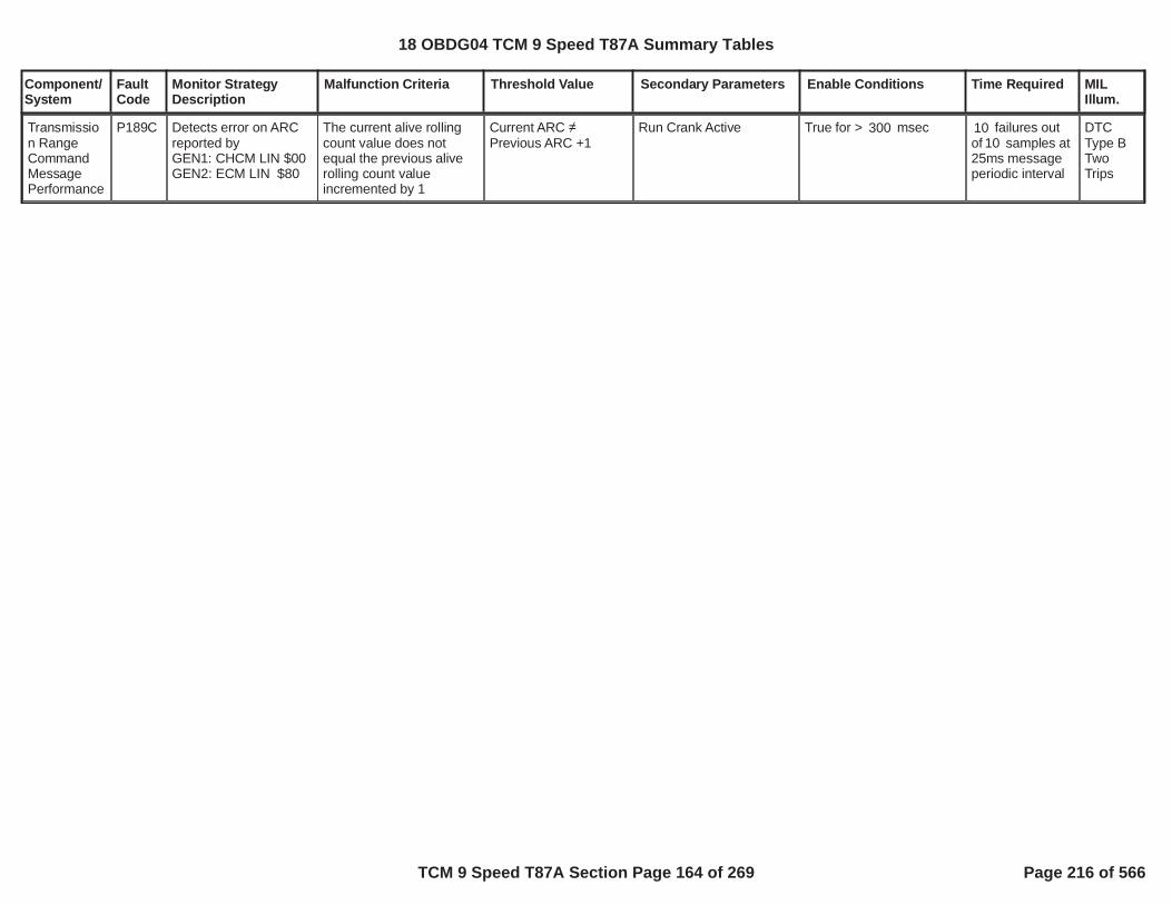
Component/System
FaultCode
Monitor StrategyDescription
Malfunction Criteria Threshold Value Secondary Parameters Enable Conditions Time Required MILIllum.
Transmission RangeCommandMessagePerformance
P189C Detects error on ARCreported byGEN1: CHCM LIN $00GEN2: ECM LIN $80
The current alive rollingcount value does notequal the previous aliverolling count valueincremented by 1
Current ARC Previous ARC +1
Run Crank Active True for > msec300 failures out10of samples at1025ms messageperiodic interval
DTCType BTwoTrips
18 OBDG04 TCM 9 Speed T87A Summary Tables
TCM 9 Speed T87A Section Page 164 of 269 Page 216 of 566

Component/System
FaultCode
Monitor StrategyDescription
Malfunction Criteria Threshold Value Secondary Parameters Enable Conditions Time Required MILIllum.
Transmission Park InhibitActuatorControlCircuit Low
P18A2 Controller specificcircuit diagnosesinternal ETRS parksolenoid for an groundshort or open circuitfailure by comparing avoltage measurementto controller specificvoltage thresholds.
Voltage measurementoutside of controllerspecific acceptable rangeindicates an open circuit
Controller specific circuitvoltage thresholds are setto meet the followingcontroller specification foran open circuit
Increment fail time
200 K impedancebetween signal andcontroller groundOR 0.5 impedance
between signal andcontroller ground
battery voltage
run crank voltageORaccessory voltage active
diagnostic monitor enablecalibration
volts and9.00volts32.00
volts5.00
= TRUE
= Boolean1
seconds1.000
25 milliseconds
12.5 milliseconds
fail time 0.300seconds out ofsample time
seconds0.500
Type A,1 Trips
18 OBDG04 TCM 9 Speed T87A Summary Tables
TCM 9 Speed T87A Section Page 165 of 269 Page 217 of 566

Component/System
FaultCode
Monitor StrategyDescription
Malfunction Criteria Threshold Value Secondary Parameters Enable Conditions Time Required MILIllum.
Transmission Park InhibitActuatorControlCircuit High
P18A4 Controller specificcircuit diagnosesinternal ETRS parksolenoid for a short tovoltage circuit failure bycomparing a voltagemeasurement tocontroller specificvoltage thresholds.
Voltage measurementoutside of controllerspecific acceptable rangeindicates a short tovoltage
Controller specific circuitvoltage thresholds are setto meet the followingcontroller specification fora short to voltage
Increment fail time
0.5 impedancebetween signal andcontroller voltagesource
battery voltage
run crank voltageORaccessory voltage active
diagnostic monitor enablecalibration
volts and9.00volts32.00
volts5.00
= TRUE
= Boolean1
seconds1.000
25 milliseconds
12.5 milliseconds
fail time 0.300seconds out ofsample time
seconds0.500
Type A,1 Trips
18 OBDG04 TCM 9 Speed T87A Summary Tables
TCM 9 Speed T87A Section Page 166 of 269 Page 218 of 566

Component/System
FaultCode
Monitor StrategyDescription
Malfunction Criteria Threshold Value Secondary Parameters Enable Conditions Time Required MILIllum.
when:mode valve A positionmode valve B positionupdate fail time
= mode valve low= mode valve low
park servo enableETRS system type isinternal ETRSbattery voltagefor battery voltage time
hydraulic pressureavailable = TRUE when:engine speedfor engine speed timeotherwise hydraulicpressure available =FALSE
engine mode runhydraulic pressureavailablesurge accumulator on/offrequestengine off diagnosticenable(ETRS commanddirection ORETRS command directionORETRS command directionORETRS command directionORETRS commanddirection)P18A8 Test Fail This KeyOnout of park state
= Boolean1=CeTRGR_e_InternalETRS
volts9.00seconds1.000
RPM400.0
KtTMDC_t_EngOnHydPresThrsh
= FALSE= FALSE
= FALSE
= Boolean1
= DRIVE
= REVERSE
= NEUTRAL LOW
= NEUTRAL HIGH
= NEUTRAL SHIFT
= FALSE
OUT OF PARK
fail time KtPSDR_t_PISA_EngOff_Lim
update rate 6.25milliseconds
Park InhibitSolenoidStuck Off
P18A8 This diagnostic monitorrationalizes the parkinhibit solenoid basedon the driver ETRScommand direction andmode valve states.
Type A,1 Trips
when:ETRS command directionP18A8 Test Fail This Key
Ondiagnostic park state
= NEUTRAL LOW= FALSE
= OUT OF PARK
park servo enableETRS system type isinternal ETRSbattery voltagefor battery voltage time
= Boolean1=CeTRGR_e_InternalETRS
fail time KtPSDR_t_PISA_EngOff_Lim
update rate 6.25
18 OBDG04 TCM 9 Speed T87A Summary Tables
TCM 9 Speed T87A Section Page 167 of 269 Page 219 of 566

Component/System
FaultCode
Monitor StrategyDescription
Malfunction Criteria Threshold Value Secondary Parameters Enable Conditions Time Required MILIllum.
mode valve A positionmode valve B positionout of park state
update fail time
= mode valve low= mode valve low OUT OF PARK
ignition inputs powermode
hydraulic pressureavailable = TRUE when:engine speedfor engine speed timeotherwise hydraulicpressure available =FALSE
hydraulic pressureavailable((out of park state ORout of park state) ANDP187D, P187E Test FailThis Key On)ETRS command direction
volts9.00seconds1.000
power mode off
RPM400.0
KtTMDC_t_EngOnHydPresThrsh
= TRUE
= PARK= OUT OF PARK= FALSE
PARK
milliseconds
18 OBDG04 TCM 9 Speed T87A Summary Tables
TCM 9 Speed T87A Section Page 168 of 269 Page 220 of 566

Component/System
FaultCode
Monitor StrategyDescription
Malfunction Criteria Threshold Value Secondary Parameters Enable Conditions Time Required MILIllum.
Transmission RangeControl APositionSensor/SwitchCircuit StuckOn
P18AA This diagnostic monitordetects a Mode Valve APosition Sensor Statein the "on" or "high"state, which is in error,when hydraulicpressure in the circuitused to move the modevalve is not sufficient toovercome the modevalve return springforce, leaving the modevalve mechanically inthe “off” or “low” state.
Mode Valve A PositionSensor State
Mode Valve Low diagnostic monitor enableETRS systemconfiguration is internalERTSbattery voltagebatyer voltage timeengine run modehydraulic system pressureavailablesurge accumulator on/offrequestGF9 engine off diagnsoticenableP18AA Test Fail This KeyOnMode Valve A PositionSensor State
Mode Valve A delay time
= Boolean1=CeTRGR_e_InternalETRS
volts9.00seconds1.00
= FALSE= FALSE
= FALSE
= Boolean1
= FALSE
Mode Valve Low(updates Mode Valve Adelay time)
KtPSDR_t_ModeVlvA_EngOff_Lim
KtPSDR_t_ModeVlvA_EngOff_Lim
update rate 6.25milleseconds
Type A,1 Trips
18 OBDG04 TCM 9 Speed T87A Summary Tables
TCM 9 Speed T87A Section Page 169 of 269 Page 221 of 566

Component/System
FaultCode
Monitor StrategyDescription
Malfunction Criteria Threshold Value Secondary Parameters Enable Conditions Time Required MILIllum.
Transmission RangeControl BPositionSensor/SwitchCircuit StuckOn
P18AC This diagnostic monitordetects a Mode Valve BPosition Sensor Statein the "on" or "high"state, which is in error,when hydraulicpressure in the circuitused to move the modevalve is not sufficient toovercome the modevalve return springforce, leaving the modevalve mechanically inthe “off” or “low” state.
Mode Valve B PositionSensor State
Mode Valve Low diagnostic monitor enableETRS systemconfiguration is internalERTSbattery voltagebatyer voltage timeengine run modehydraulic system pressureavailablesurge accumulator on/offrequestGF9 engine off diagnsoticenableP18A Test Fail This KeyOnMode Valve A PositionSensor State
Mode Valve A delay time
= Boolean1=CeTRGR_e_InternalETRS
volts9.00seconds1.00
= FALSE= FALSE
= FALSE
= Boolean1
= FALSE
Mode Valve Low(updates Mode Valve Bdelay time)
KtPSDR_t_ModeVlvB_EngOff_Lim
KtPSDR_t_ModeVlvB_EngOff_Lim
update rate 6.25milleseconds
Type A,1 Trips
18 OBDG04 TCM 9 Speed T87A Summary Tables
TCM 9 Speed T87A Section Page 170 of 269 Page 222 of 566

Component/System
FaultCode
Monitor StrategyDescription
Malfunction Criteria Threshold Value Secondary Parameters Enable Conditions Time Required MILIllum.
ActuatorSupplyVoltage BCircuit Low
P2670 Controller specificoutput driver circuitdiagnoses the highsided driver circuit for ashort to ground failurewhen the output ispowered on bycomparing a voltagemeasurement tocontroller specificvoltage thresholds.
Voltage measurementoutside of controllerspecific acceptable rangeduring driver on stateindicates short to groundfailure.
Controller specific outputdriver circuit voltagethresholds are set to meetthe following controllerspecification for a short toground.
0.5 impedancebetween signal andcontroller ground
diagnostic monitor enablehigh side drive 2 ONP2670 fault activeP2670 test fail this key on
= Boolean1= TRUE= FALSE= FALSE
fail count 6countsout of samplecount 2,400counts
6.25 millisecondupdate rate
Type A,1 Trips
18 OBDG04 TCM 9 Speed T87A Summary Tables
TCM 9 Speed T87A Section Page 171 of 269 Page 223 of 566

Component/System
FaultCode
Monitor StrategyDescription
Malfunction Criteria Threshold Value Secondary Parameters Enable Conditions Time Required MILIllum.
PressureControl (PC)Solenoid DStuck Off
P2714 Each pressure controlsolenoid stuck offdiagnostic monitordetects a clutchpressure controlsolenoid failedhydraulically off, whilethe solenoid iselectrically functional.In the failure mode theclutch slip speed, andgear box gear slip, willbe excessive, not nearor at zero RPM. Theclutch slip speed iscalculated based onthe transmission levernode design, requiringtransmission input shaftspeed, transmissionoutput shaft speed,and, one transmissionintermediate shaftspeed. The clutchpressure controlsolenoid is tested afteran automatictransmission shiftoccurs and has beenconsidered shiftcomplete, or, steadystate gear is deemedactive, range shiftcomplete. When theautomatic transmissionshift is complete,steady state gear isconsidered, the clutchpressure controlsolenoid is mapped totransmission line
C1 clutch slip speed,update fail time6.25 milliscond update
RPM200.0
use battery voltagecalibration is FALSEOR(use battery voltagecalibration is TRUEANDbattery voltage
use run crank voltagecalibration is FALSEOR(use run crank voltagecalibration is TRUEANDrun crank voltage
TCM output driver highside driver 1, clutchpressure control solenoiddriver circuit enabled
TCM output driver highside driver 2, clutchpressure control solenoiddriver circuit enabled
service fast learn activeservice solenoid cleaningprocedure active
hydraulic pressure
= Boolean1
= Boolean1
volts9.00
= Boolean0
= Boolean0
volts9.00
= TRUE Boolean
= TRUE Boolean
= FALSE Boolean= FALSE Boolean
fail time 3.00seconds,update fail count,fail count 3counts6.25 milliscondupdate
battery voltagetime 0.100seconds
run crank voltagetime 0.100seconds
Type A,1 Trips
18 OBDG04 TCM 9 Speed T87A Summary Tables
TCM 9 Speed T87A Section Page 172 of 269 Page 224 of 566
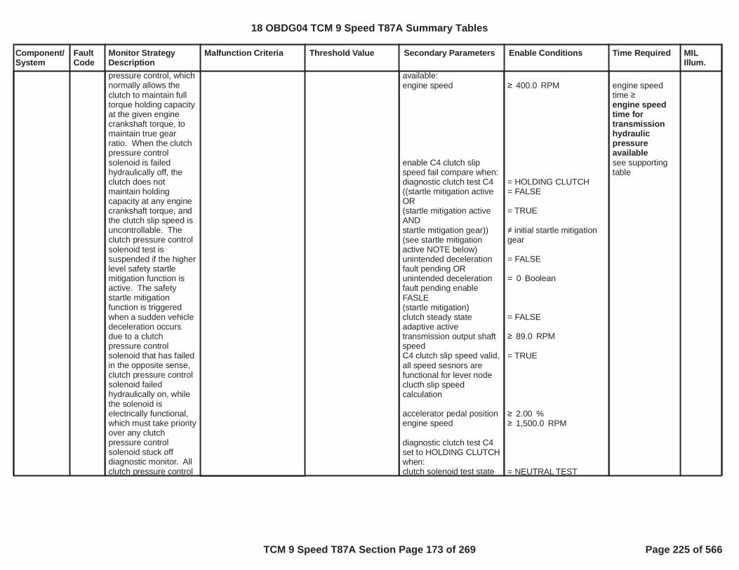
Component/System
FaultCode
Monitor StrategyDescription
Malfunction Criteria Threshold Value Secondary Parameters Enable Conditions Time Required MILIllum.
pressure control, whichnormally allows theclutch to maintain fulltorque holding capacityat the given enginecrankshaft torque, tomaintain true gearratio. When the clutchpressure controlsolenoid is failedhydraulically off, theclutch does notmaintain holdingcapacity at any enginecrankshaft torque, andthe clutch slip speed isuncontrollable. Theclutch pressure controlsolenoid test issuspended if the higherlevel safety startlemitigation function isactive. The safetystartle mitigationfunction is triggeredwhen a sudden vehicledeceleration occursdue to a clutchpressure controlsolenoid that has failedin the opposite sense,clutch pressure controlsolenoid failedhydraulically on, whilethe solenoid iselectrically functional,which must take priorityover any clutchpressure controlsolenoid stuck offdiagnostic monitor. Allclutch pressure control
available:engine speed
enable C4 clutch slipspeed fail compare when:diagnostic clutch test C4((startle mitigation activeOR(startle mitigation activeANDstartle mitigation gear))(see startle mitigationactive NOTE below)unintended decelerationfault pending ORunintended decelerationfault pending enableFASLE(startle mitigation)clutch steady stateadaptive activetransmission output shaftspeedC4 clutch slip speed valid,all speed sesnors arefunctional for lever nodeclucth slip speedcalculation
accelerator pedal positionengine speed
diagnostic clutch test C4set to HOLDING CLUTCHwhen:clutch solenoid test state
RPM400.0
= HOLDING CLUTCH= FALSE
= TRUE
initial startle mitigationgear
= FALSE
= Boolean0
= FALSE
RPM89.0
= TRUE
%2.00RPM1,500.0
= NEUTRAL TEST
engine speedtime engine speedtime fortransmissionhydraulicpressureavailablesee supportingtable
18 OBDG04 TCM 9 Speed T87A Summary Tables
TCM 9 Speed T87A Section Page 173 of 269 Page 225 of 566

Component/System
FaultCode
Monitor StrategyDescription
Malfunction Criteria Threshold Value Secondary Parameters Enable Conditions Time Required MILIllum.
solenoid stuck on/offdiagnostic monitors areemission MIL DTCs.System voltage mustbe normal, all clutchpressure controlsolenoid driver circuitsmust be functional, noclutch pressure controlsolenoid electrical orperformance faults canbe present, and nospeed sensor electricalor performance faultscan be present, or thea clutch pressurecontrol solenoid stuckoff test is disabled.This diagnostic monitoris relative to the GF9C4 C4, or, GR10 C4C123467810R, clutchpressure controlsolenoid.
((startle mitigation activeOR(startle mitigation activeANDstartle mitigation gear))(see startle mitigationactive NOTE below)C4 clutch pressured map
clutch solenoid test stateset to NEUTRAL TESTwhen:test triggerinitialize range shiftcomplete time,whenrange shift state,range shift complete timemust time down to zerowhenrange shift complete
test trigger set to TRUE:enable forward gear ANDdirection requestORenable reverse gear ANDdirection requestcurrent loop test triggerclutch control solenoidtest staterange shift state
NOTE: startle mitigationactive is used to detectunintended decelerationdue to clutch pressurecontrol solenoid stuck on
= FALSE
= TRUE
initial startle mitigationgear
= mapped to linepressure, C4 clutchpressure has transtionedfrom off-applying-applied
= TRUE
range shift completed
= Boolean1= forward gear
= Boolean0= reverse gear= FALSE NEUTRAL TEST
= range shift completed
initialize rangeshift completetime = 1.000seconds,range shiftcomplete timemust time downto zerowhenrange shiftcomplete
18 OBDG04 TCM 9 Speed T87A Summary Tables
TCM 9 Speed T87A Section Page 174 of 269 Page 226 of 566

Component/System
FaultCode
Monitor StrategyDescription
Malfunction Criteria Threshold Value Secondary Parameters Enable Conditions Time Required MILIllum.
failure modes, the clutchpressure control solenoidstuck on DTCs beingP0747 P0777 P0797P2715 P2724 P2733P2821
DTCs not fault pending
DTCs not test fail this keyon
DTCs not fault active
P0716 P0717 P0722P0723 P077C P077DP07BF P07C0
P0707 P0708 P0746P0747 P0776 P0777P0796 P0797 P2714P2715 P2723 P2724P2732 P2733 P2820P2821
AcceleratorPedalFailureCrankSensor_FAP0707 P0708 P0716P0717 P07BF P07C0P0722 P0723 P077CP077D P172A P172BP176B P176C P176DP17C5 P17CC P17CDP17CE P17D3 P17D6P2805
18 OBDG04 TCM 9 Speed T87A Summary Tables
TCM 9 Speed T87A Section Page 175 of 269 Page 227 of 566

Component/System
FaultCode
Monitor StrategyDescription
Malfunction Criteria Threshold Value Secondary Parameters Enable Conditions Time Required MILIllum.
PressureControl (PC)Solenoid DStuck On
P2715 Each pressure controlsolenoid stuck ondiagnostic monitordetects a clutchpressure controlsolenoid failedhydraulically on, whilethe solenoid iselectrically functional.The clutch pressurecontrol solenoid istested during anautomatic transmissionshift by monitoring theoff going clutch slipspeed. With the clutchpressure controlsolenoid failed on, stillallowing hydraulicpressure to the clutchbeing commanded off,the intended off goingclutch continues tomaintain torquecapacity during thetransmission automaticshift. In the failuremode, the off goingclutch slip speed willremain near zero RPMwhen the clutchpressure controlsolenoid is commandedto an off pressure in thenormal operation torelease the holdingclutch. The clutch slipspeed is calculatedbased on thetransmission levernode design, requiring
shift type is power downshift,C4 clutch slip speedORshift type is not powerdown shift,C4 clutch slip speed
update fail time6.25 milliscond update
< RPM50.0
< RPM50.0
use battery voltagecalibration is FALSEOR(use battery voltagecalibration is TRUEANDbattery voltage
use run crank voltagecalibration is FALSEOR(use run crank voltagecalibration is TRUEANDrun crank voltage
TCM output driver highside driver 1, clutchpressure control solenoiddriver circuit enabled
= Boolean1
= Boolean1
volts9.00
= Boolean0
= Boolean0
volts9.00
= TRUE Boolean
shift type ispower downshift,fail time 0.800seconds,ORshift type is notpower downshift,fail time 0.150seconds,
update fail count,fail count 3counts6.25 milliscondupdate
battery voltagetime 0.100seconds
run crank voltagetime 0.100seconds
Type A,1 Trips
18 OBDG04 TCM 9 Speed T87A Summary Tables
TCM 9 Speed T87A Section Page 176 of 269 Page 228 of 566

Component/System
FaultCode
Monitor StrategyDescription
Malfunction Criteria Threshold Value Secondary Parameters Enable Conditions Time Required MILIllum.
transmission input shaftspeed, transmissionoutput shaft speed,and, one transmissionintermediate shaftspeed. As part of thepressure controlsolenoid stuck ondiagnostic monitor, thesafety startle mitigationfunction executes whenin steady state gear, noautomatic transmissionshift in progress. Thesafety startle mitigationfunction is triggeredwhen a sudden vehicledeceleration occursdue to a clutchpressure controlsolenoid that has failedhydraulically on, whilethe solenoid iselectrically functional.All clutch pressurecontrol solenoid stuckon diagnostic monitorsare emission MILDTCs. System voltagemust be normal, allclutch pressure controlsolenoid driver circuitsmust be functional, noclutch pressure controlsolenoid electrical orperformance faults canbe present, and nospeed sensor electricalor performance faultscan be present, or thea clutch pressurecontrol solenoid stuck
TCM output driver highside driver 2, clutchpressure control solenoiddriver circuit enabled
service fast learn activeservice solenoid cleaningprocedure active
hydraulic pressureavailable:engine speed
transmission output shaftspeed
set solenoid stuck on testtrigger to TRUE when:clutch pressure controlsolenoid stuck off stuckintrusive shift requeststartle mitigation active(see startle mitigationactive NOTE below)clutch control solenoidtest stateclutch control solenoidtest state (see clutchcontrol solenoid test stateNOTE below)initialize active clutchcontroller (clutch controlprocessing in process ofsequencing clutches on
= TRUE Boolean
= FALSE Boolean= FALSE Boolean
RPM400.0
RPM89.0
= FALSE
= FALSE
TIE UP TEST TESTSTATE TIE UP TEST HOLD
= TRUE
engine speedtime engine speedtime fortransmissionhydraulicpressureavailablesee supportingtable
18 OBDG04 TCM 9 Speed T87A Summary Tables
TCM 9 Speed T87A Section Page 177 of 269 Page 229 of 566

Component/System
FaultCode
Monitor StrategyDescription
Malfunction Criteria Threshold Value Secondary Parameters Enable Conditions Time Required MILIllum.
on test is disabled.This diagnostic monitoris relative to the GF9C4 C4, or, GR10 C4C123467810R, clutchpressure controlsolenoid.
and off for auto trans shift)(shift type enable forstaged steady state shift -shift in process when newshift type occurs -interrupted shiftORshift type enable forgarage shiftORshift type enable fornegative torque up shiftORshift type enable for openthrottle power on up shiftORshift type enable forclosed throttle down shiftORshift type enable for openthrottle power down shiftORshift type enable forclosed throttle lift foot upshift )ORclutch control solenoidtest stateclutch control solenoidtest state (see clutchcontrol solenoid test stateNOTE below)transition clutch controlleractive clutch controller(staged steady sate shift -shift not in process, nonew shift type occuring,no interrupted shift)
set clutch control solenoidtest state to TIE UP TEST
= Boolean0
= Boolean0
= Boolean1
= Boolean1
= Boolean1
= Boolean1
= Boolean0
= TIE UP TEST TESTSTATE= TIE UP TEST HOLD
= TRUE staged steady state
18 OBDG04 TCM 9 Speed T87A Summary Tables
TCM 9 Speed T87A Section Page 178 of 269 Page 230 of 566

Component/System
FaultCode
Monitor StrategyDescription
Malfunction Criteria Threshold Value Secondary Parameters Enable Conditions Time Required MILIllum.
TEST STATE when:solenoid stuck on testtriggercurrent loop clutch controlsolenoid test stateORcurrent loop clutch controlsolenoid test state (seeclutch control solenoidtest state NOTE below)range shift statesolenoid stuck on testtriggeradditional off going clutchoccured
(clutch control solenoidtest state ORclutch control solenoidtest state) (see clutchcontrol solenoid test stateNOTE below)diagnostic clutch test
(C4 off going clutchpressure control ramptime out complete ANDoff going clutch pressureramp control ramp timeout enable)ORC4 off going clutchpressure
= TRUE
= TEST WAITING
= TIE UP TEST HOLD
range shift complete= TRUE
= TRUE
= TIE UP TEST TESTSTATE= TIE UP TEST HOLD
= OFF GOING CLUTCHTEST= TRUE
= Boolean1
kPa350.0 for C4 off goingclutch pressuretime P2715 C4 clutchexhaust delaytime closedthrottle lift footup shiftOR
18 OBDG04 TCM 9 Speed T87A Summary Tables
TCM 9 Speed T87A Section Page 179 of 269 Page 231 of 566

Component/System
FaultCode
Monitor StrategyDescription
Malfunction Criteria Threshold Value Secondary Parameters Enable Conditions Time Required MILIllum.
engine torqueprimary on coming clutchactiveprimary on coming controlstateclosed throttle lift foot upshift primary on comingclutch pressureORopen throttle power on upshift primary on comingclutch pressureORgarage shift primary on
Nm8,191.8= TRUE
clutch fill phase
kPa850.0
kPA850.0
kPa750.0
P2715 C4 clutchexhaust delaytime openthrottle poweron up shiftORP2715 C4 clutchexhaust delaytime garageshiftORP2715 C4 clutchexhaust delaytime closedthrottle downshiftORP2715 C4 clutchexhaust delaytime negativetorque up shiftORP2715 C4 clutchexhaust delaytime openthrottle powerdown shiftsee supportingtables
18 OBDG04 TCM 9 Speed T87A Summary Tables
TCM 9 Speed T87A Section Page 180 of 269 Page 232 of 566

Component/System
FaultCode
Monitor StrategyDescription
Malfunction Criteria Threshold Value Secondary Parameters Enable Conditions Time Required MILIllum.
coming clutch pressureORnegative torque up shiftprimary on coming clutchpressureORopen throttle power downshift primary on comingclutch pressureORclosed throttle down shiftprimary on coming clutchpressureC4 clutch slip speed valid,all speed sesnors arefunctional for lever nodeclucth slip speedcalculation
NOTE: Clutch controlsolenoid test state TIE UPTEST HOLD is necessary,as it is possible to havemultiple off going clutchesduring one automatictransmission shift. Clutchcontrol solenoid test stateis set to TIE UP TESTHOLD during anautomatic transmissionshift due to twoconditions:Current value of clutchcontrol solenoid test stateis TIE UP TEST TESTSTATE, when one offgoing clutch pressurecontrol solenoid stuck ondiagnostic monitor iscurrently executing.AND
kPa850.0
kPa850.0
kPa850.0
= TRUE
18 OBDG04 TCM 9 Speed T87A Summary Tables
TCM 9 Speed T87A Section Page 181 of 269 Page 233 of 566

Component/System
FaultCode
Monitor StrategyDescription
Malfunction Criteria Threshold Value Secondary Parameters Enable Conditions Time Required MILIllum.
That off going clutchpressure control solenoidstuck on diagnosticmonitor currentlyexecuting passes, thecorresponding clutch slipspeed clutch slip speedfail threshold.Once clutch controlsolenoid test state is setto TIE UP TEST HOLD, itremains TIE UP TESTHOLD during theautomatic transmissionshift, until:An additional off goingclutch occurs, asindicated by solenoidstuck on test trigger =TRUE, subsequentlyclutch control solenoidtest state is reset to TIEUP TEST TEST STATE, toallow the additionalcorresponding off goingclutch pressure controlsolenoid stuck ondiagnostic monitor toexecute.ORThe automatictransmission shiftcompletes, range shiftstate = range shiftcomplete.
NOTE: Startle mitigationis used to detectunintended vehicledeceleration due to aclutch pressure control
18 OBDG04 TCM 9 Speed T87A Summary Tables
TCM 9 Speed T87A Section Page 182 of 269 Page 234 of 566

Component/System
FaultCode
Monitor StrategyDescription
Malfunction Criteria Threshold Value Secondary Parameters Enable Conditions Time Required MILIllum.
solenoid stuck on failuremode that occurs duringsteady state gear, notduring an automatictransmission shift. Thestartle mitigation activethen forces thetransmission clutchpressure control systemto a safe gear or neutralstate, based on the activeand inactive clutches,when the unintendedvehicle decelerationoccurred. Once a safevehicle gear state isattained, the gear andclutch pressure controlsystem allows transitionsof the clutches on and off,to sequence automatictransmission shifts, singlestep shifts. As eachsingle step automatictransmission shift occursthe normal pressurecontrol solenoid stuck ondiagnostic monitorsexecute to verify whichclutch pressure controlsolenoid is in the stuck onfailure mode, allowing oneof the clutch pressurecontrol solenoid stuck onDTCs to set P0747,P0777, P0797, P2715,P2724, P2733, P2821.
DTCs not fault pending P0716 P0717 P0722P0723 P077C P077DP07BF P07C0
18 OBDG04 TCM 9 Speed T87A Summary Tables
TCM 9 Speed T87A Section Page 183 of 269 Page 235 of 566

Component/System
FaultCode
Monitor StrategyDescription
Malfunction Criteria Threshold Value Secondary Parameters Enable Conditions Time Required MILIllum.
DTCs not test fail this keyon
DTCs not fault active
P0707 P0708 P0746P0747 P0776 P0777P0796 P0797 P2714P2715 P2723 P2724P2732 P2733 P2820P2821
AcceleratorPedalFailureCrankSensor_FAP0707 P0708 P0716P0717 P07BF P07C0P0722 P0723 P077CP077D P172A P172BP176B P176C P176DP17C5 P17CC P17CDP17CE P17D3 P17D6P2805
18 OBDG04 TCM 9 Speed T87A Summary Tables
TCM 9 Speed T87A Section Page 184 of 269 Page 236 of 566

Component/System
FaultCode
Monitor StrategyDescription
Malfunction Criteria Threshold Value Secondary Parameters Enable Conditions Time Required MILIllum.
PressureControl (PC)Solenoid DControlCircuit Open
P2718 Controller specificcircuit diagnoses 9speed C4 or 10 speedC123467810R clutchsolenoid for an opencircuit failure bycomparing a voltagemeasurement tocontroller specificvoltage thresholds.
Voltage measurementoutside of controllerspecific acceptable rangeindicates an open circuit
Controller specific circuitvoltage thresholds are setto meet the followingcontroller specification foran open circuit
Increment fail time
200 K impedancebetween signal andcontroller ground
battery voltage
run crank voltageORaccessory voltage active
diagnostic monitor enablecalibration
volts and9.00volts32.00
volts5.00
= TRUE
= Boolean1
seconds1.000
25 milliseconds
12.5 milliseconds
fail time 0.300seconds out ofsample time
seconds0.500
Type A,1 Trips
18 OBDG04 TCM 9 Speed T87A Summary Tables
TCM 9 Speed T87A Section Page 185 of 269 Page 237 of 566

Component/System
FaultCode
Monitor StrategyDescription
Malfunction Criteria Threshold Value Secondary Parameters Enable Conditions Time Required MILIllum.
PressureControl (PC)Solenoid DControlCircuit Low
P2720 Controller specificcircuit diagnoses 9speed C4 or 10 speedC123467810R clutchsolenoid for a groundshort circuit failure bycomparing a voltagemeasurement tocontroller specificvoltage thresholds.
Voltage measurementoutside of controllerspecific acceptable rangeindicates a ground short
Controller specific circuitvoltage thresholds are setto meet the followingcontroller specification fora ground short
Increment fail time
0.5 impedancebetween signal andcontroller ground
battery voltage
run crank voltageORaccessory voltage active
diagnostic monitor enablecalibration
volts and9.00volts32.00
volts5.00
= TRUE
= Boolean1
seconds1.000
25 milliseconds
12.5 milliseconds
fail time 0.300seconds out ofsample time s
econds0.500
Type A,1 Trips
18 OBDG04 TCM 9 Speed T87A Summary Tables
TCM 9 Speed T87A Section Page 186 of 269 Page 238 of 566

Component/System
FaultCode
Monitor StrategyDescription
Malfunction Criteria Threshold Value Secondary Parameters Enable Conditions Time Required MILIllum.
PressureControl (PC)Solenoid DControlCircuit High
P2721 Controller specificcircuit diagnoses 9speed C4 or 10 speedC123467810R clutchsolenoid for a short tovoltage circuit failure bycomparing a voltagemeasurement tocontroller specificvoltage thresholds.
Voltage measurementoutside of controllerspecific acceptable rangeindicates a short tovoltage
Controller specific circuitvoltage thresholds are setto meet the followingcontroller specification fora short to voltage
Increment fail time
0.5 impedancebetween signal andcontroller voltagesource
battery voltage
run crank voltageORaccessory voltage active
diagnostic monitor enablecalibration
volts and9.00volts32.00
volts5.00
= TRUE
= Boolean1
seconds1.000
25 milliseconds
12.5 milliseconds
fail time 0.300seconds out ofsample time
seconds0.500
Type A,1 Trips
18 OBDG04 TCM 9 Speed T87A Summary Tables
TCM 9 Speed T87A Section Page 187 of 269 Page 239 of 566

Component/System
FaultCode
Monitor StrategyDescription
Malfunction Criteria Threshold Value Secondary Parameters Enable Conditions Time Required MILIllum.
PressureControl (PC)Solenoid EStuck Off
P2723 Each pressure controlsolenoid stuck offdiagnostic monitordetects a clutchpressure controlsolenoid failedhydraulically off, whilethe solenoid iselectrically functional.In the failure mode theclutch slip speed, andgear box gear slip, willbe excessive, not nearor at zero RPM. Theclutch slip speed iscalculated based onthe transmission levernode design, requiringtransmission input shaftspeed, transmissionoutput shaft speed,and, one transmissionintermediate shaftspeed. The clutchpressure controlsolenoid is tested afteran automatictransmission shiftoccurs and has beenconsidered shiftcomplete, or, steadystate gear is deemedactive, range shiftcomplete. When theautomatic transmissionshift is complete,steady state gear isconsidered, the clutchpressure controlsolenoid is mapped totransmission line
C1 clutch slip speed,update fail time6.25 milliscond update
RPM200.0
use battery voltagecalibration is FALSEOR(use battery voltagecalibration is TRUEANDbattery voltage
use run crank voltagecalibration is FALSEOR(use run crank voltagecalibration is TRUEANDrun crank voltage
TCM output driver highside driver 1, clutchpressure control solenoiddriver circuit enabled
TCM output driver highside driver 2, clutchpressure control solenoiddriver circuit enabled
service fast learn activeservice solenoid cleaningprocedure active
hydraulic pressure
= Boolean1
= Boolean1
volts9.00
= Boolean0
= Boolean0
volts9.00
= TRUE Boolean
= TRUE Boolean
= FALSE Boolean= FALSE Boolean
fail time 3.00seconds,update fail count,fail count 3counts6.25 milliscondupdate
battery voltagetime 0.100seconds
run crank voltagetime 0.100seconds
Type A,1 Trips
18 OBDG04 TCM 9 Speed T87A Summary Tables
TCM 9 Speed T87A Section Page 188 of 269 Page 240 of 566

Component/System
FaultCode
Monitor StrategyDescription
Malfunction Criteria Threshold Value Secondary Parameters Enable Conditions Time Required MILIllum.
pressure control, whichnormally allows theclutch to maintain fulltorque holding capacityat the given enginecrankshaft torque, tomaintain true gearratio. When the clutchpressure controlsolenoid is failedhydraulically off, theclutch does notmaintain holdingcapacity at any enginecrankshaft torque, andthe clutch slip speed isuncontrollable. Theclutch pressure controlsolenoid test issuspended if the higherlevel safety startlemitigation function isactive. The safetystartle mitigationfunction is triggeredwhen a sudden vehicledeceleration occursdue to a clutchpressure controlsolenoid that has failedin the opposite sense,clutch pressure controlsolenoid failedhydraulically on, whilethe solenoid iselectrically functional,which must take priorityover any clutchpressure controlsolenoid stuck offdiagnostic monitor. Allclutch pressure control
available:engine speed
enable C5 clutch slipspeed fail compare when:diagnostic clutch test C5((startle mitigation activeOR(startle mitigation activeANDstartle mitigation gear))(see startle mitigationactive NOTE below)unintended decelerationfault pending ORunintended decelerationfault pending enableFASLE(startle mitigation)clutch steady stateadaptive activetransmission output shaftspeedC5 clutch slip speed valid,all speed sesnors arefunctional for lever nodeclucth slip speedcalculation
accelerator pedal positionengine speed
diagnostic clutch test C5set to HOLDING CLUTCHwhen:clutch solenoid test state
RPM400.0
= HOLDING CLUTCH= FALSE
= TRUE
initial startle mitigationgear
= FALSE
= Boolean0
= FALSE
RPM89.0
= TRUE
%2.00RPM1,500.0
= NEUTRAL TEST
engine speedtime engine speedtime fortransmissionhydraulicpressureavailablesee supportingtable
18 OBDG04 TCM 9 Speed T87A Summary Tables
TCM 9 Speed T87A Section Page 189 of 269 Page 241 of 566

Component/System
FaultCode
Monitor StrategyDescription
Malfunction Criteria Threshold Value Secondary Parameters Enable Conditions Time Required MILIllum.
solenoid stuck on/offdiagnostic monitors areemission MIL DTCs.System voltage mustbe normal, all clutchpressure controlsolenoid driver circuitsmust be functional, noclutch pressure controlsolenoid electrical orperformance faults canbe present, and nospeed sensor electricalor performance faultscan be present, or thea clutch pressurecontrol solenoid stuckoff test is disabled.This diagnostic monitoris relative to the GF9C5 C57R, or, GR10 C5C1356789, clutchpressure controlsolenoid.
((startle mitigation activeOR(startle mitigation activeANDstartle mitigation gear))(see startle mitigationactive NOTE below)C5 clutch pressured map
clutch solenoid test stateset to NEUTRAL TESTwhen:test triggerinitialize range shiftcomplete time,whenrange shift state,range shift complete timemust time down to zerowhenrange shift complete
test trigger set to TRUE:enable forward gear ANDdirection requestORenable reverse gear ANDdirection requestcurrent loop test triggerclutch control solenoidtest staterange shift state
NOTE: startle mitigationactive is used to detectunintended decelerationdue to clutch pressurecontrol solenoid stuck on
= FALSE
= TRUE
initial startle mitigationgear
= mapped to linepressure, C5 clutchpressure has transtionedfrom off-applying-applied
= TRUE
range shift completed
= Boolean1= forward gear
= Boolean0= reverse gear= FALSE NEUTRAL TEST
= range shift completed
initialize rangeshift completetime = 1.000seconds,range shiftcomplete timemust time downto zerowhenrange shiftcomplete
18 OBDG04 TCM 9 Speed T87A Summary Tables
TCM 9 Speed T87A Section Page 190 of 269 Page 242 of 566
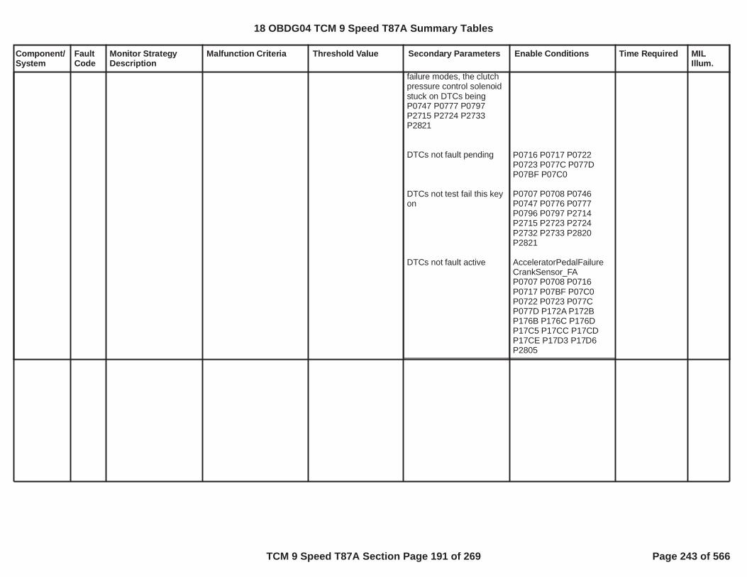
Component/System
FaultCode
Monitor StrategyDescription
Malfunction Criteria Threshold Value Secondary Parameters Enable Conditions Time Required MILIllum.
failure modes, the clutchpressure control solenoidstuck on DTCs beingP0747 P0777 P0797P2715 P2724 P2733P2821
DTCs not fault pending
DTCs not test fail this keyon
DTCs not fault active
P0716 P0717 P0722P0723 P077C P077DP07BF P07C0
P0707 P0708 P0746P0747 P0776 P0777P0796 P0797 P2714P2715 P2723 P2724P2732 P2733 P2820P2821
AcceleratorPedalFailureCrankSensor_FAP0707 P0708 P0716P0717 P07BF P07C0P0722 P0723 P077CP077D P172A P172BP176B P176C P176DP17C5 P17CC P17CDP17CE P17D3 P17D6P2805
18 OBDG04 TCM 9 Speed T87A Summary Tables
TCM 9 Speed T87A Section Page 191 of 269 Page 243 of 566

Component/System
FaultCode
Monitor StrategyDescription
Malfunction Criteria Threshold Value Secondary Parameters Enable Conditions Time Required MILIllum.
PressureControl (PC)Solenoid EStuck On
P2724 Each pressure controlsolenoid stuck ondiagnostic monitordetects a clutchpressure controlsolenoid failedhydraulically on, whilethe solenoid iselectrically functional.The clutch pressurecontrol solenoid istested during anautomatic transmissionshift by monitoring theoff going clutch slipspeed. With the clutchpressure controlsolenoid failed on, stillallowing hydraulicpressure to the clutchbeing commanded off,the intended off goingclutch continues tomaintain torquecapacity during thetransmission automaticshift. In the failuremode, the off goingclutch slip speed willremain near zero RPMwhen the clutchpressure controlsolenoid is commandedto an off pressure in thenormal operation torelease the holdingclutch. The clutch slipspeed is calculatedbased on thetransmission levernode design, requiring
shift type is power downshift,C5 clutch slip speedORshift type is not powerdown shift,C5 clutch slip speed
update fail time6.25 milliscond update
< RPM50.0
< RPM50.0
use battery voltagecalibration is FALSEOR(use battery voltagecalibration is TRUEANDbattery voltage
use run crank voltagecalibration is FALSEOR(use run crank voltagecalibration is TRUEANDrun crank voltage
TCM output driver highside driver 1, clutchpressure control solenoiddriver circuit enabled
= Boolean1
= Boolean1
volts9.00
= Boolean0
= Boolean0
volts9.00
= TRUE Boolean
shift type ispower downshift,fail time 0.400seconds,ORshift type is notpower downshift,fail time 0.150seconds,
update fail count,fail count 3counts6.25 milliscondupdate
battery voltagetime 0.100seconds
run crank voltagetime 0.100seconds
Type A,1 Trips
18 OBDG04 TCM 9 Speed T87A Summary Tables
TCM 9 Speed T87A Section Page 192 of 269 Page 244 of 566

Component/System
FaultCode
Monitor StrategyDescription
Malfunction Criteria Threshold Value Secondary Parameters Enable Conditions Time Required MILIllum.
transmission input shaftspeed, transmissionoutput shaft speed,and, one transmissionintermediate shaftspeed. As part of thepressure controlsolenoid stuck ondiagnostic monitor, thesafety startle mitigationfunction executes whenin steady state gear, noautomatic transmissionshift in progress. Thesafety startle mitigationfunction is triggeredwhen a sudden vehicledeceleration occursdue to a clutchpressure controlsolenoid that has failedhydraulically on, whilethe solenoid iselectrically functional.All clutch pressurecontrol solenoid stuckon diagnostic monitorsare emission MILDTCs. System voltagemust be normal, allclutch pressure controlsolenoid driver circuitsmust be functional, noclutch pressure controlsolenoid electrical orperformance faults canbe present, and nospeed sensor electricalor performance faultscan be present, or thea clutch pressurecontrol solenoid stuck
TCM output driver highside driver 2, clutchpressure control solenoiddriver circuit enabled
service fast learn activeservice solenoid cleaningprocedure active
hydraulic pressureavailable:engine speed
transmission output shaftspeed
set solenoid stuck on testtrigger to TRUE when:clutch pressure controlsolenoid stuck off stuckintrusive shift requeststartle mitigation active(see startle mitigationactive NOTE below)clutch control solenoidtest stateclutch control solenoidtest state (see clutchcontrol solenoid test stateNOTE below)initialize active clutchcontroller (clutch controlprocessing in process ofsequencing clutches on
= TRUE Boolean
= FALSE Boolean= FALSE Boolean
RPM400.0
RPM89.0
= FALSE
= FALSE
TIE UP TEST TESTSTATE TIE UP TEST HOLD
= TRUE
engine speedtime engine speedtime fortransmissionhydraulicpressureavailablesee supportingtable
18 OBDG04 TCM 9 Speed T87A Summary Tables
TCM 9 Speed T87A Section Page 193 of 269 Page 245 of 566

Component/System
FaultCode
Monitor StrategyDescription
Malfunction Criteria Threshold Value Secondary Parameters Enable Conditions Time Required MILIllum.
on test is disabled.This diagnostic monitoris relative to the GF9C5 C57R, or, GR10 C5C1356789, clutchpressure controlsolenoid.
and off for auto trans shift)(shift type enable forstaged steady state shift -shift in process when newshift type occurs -interrupted shiftORshift type enable forgarage shiftORshift type enable fornegative torque up shiftORshift type enable for openthrottle power on up shiftORshift type enable forclosed throttle down shiftORshift type enable for openthrottle power down shiftORshift type enable forclosed throttle lift foot upshift )ORclutch control solenoidtest stateclutch control solenoidtest state (see clutchcontrol solenoid test stateNOTE below)transition clutch controlleractive clutch controller(staged steady sate shift -shift not in process, nonew shift type occuring,no interrupted shift)
set clutch control solenoidtest state to TIE UP TEST
= Boolean0
= Boolean0
= Boolean1
= Boolean1
= Boolean1
= Boolean1
= Boolean0
= TIE UP TEST TESTSTATE= TIE UP TEST HOLD
= TRUE staged steady state
18 OBDG04 TCM 9 Speed T87A Summary Tables
TCM 9 Speed T87A Section Page 194 of 269 Page 246 of 566

Component/System
FaultCode
Monitor StrategyDescription
Malfunction Criteria Threshold Value Secondary Parameters Enable Conditions Time Required MILIllum.
TEST STATE when:solenoid stuck on testtriggercurrent loop clutch controlsolenoid test stateORcurrent loop clutch controlsolenoid test state (seeclutch control solenoidtest state NOTE below)range shift statesolenoid stuck on testtriggeradditional off going clutchoccured
(clutch control solenoidtest state ORclutch control solenoidtest state) (see clutchcontrol solenoid test stateNOTE below)diagnostic clutch test
(C5 off going clutchpressure control ramptime out complete ANDoff going clutch pressureramp control ramp timeout enable)ORC5 off going clutchpressure
= TRUE
= TEST WAITING
= TIE UP TEST HOLD
range shift complete= TRUE
= TRUE
= TIE UP TEST TESTSTATE= TIE UP TEST HOLD
= OFF GOING CLUTCHTEST= TRUE
= Boolean1
kPa350.0 for C5 off goingclutch pressuretime P2724 C5 clutchexhaust delaytime closedthrottle lift footup shiftOR
18 OBDG04 TCM 9 Speed T87A Summary Tables
TCM 9 Speed T87A Section Page 195 of 269 Page 247 of 566

Component/System
FaultCode
Monitor StrategyDescription
Malfunction Criteria Threshold Value Secondary Parameters Enable Conditions Time Required MILIllum.
engine torqueprimary on coming clutchactiveprimary on coming controlstateclosed throttle lift foot upshift primary on comingclutch pressureORopen throttle power on upshift primary on comingclutch pressureORgarage shift primary on
Nm8,191.8= TRUE
clutch fill phase
kPa703.0
kPA703.0
kPa750.0
P2724 C5 clutchexhaust delaytime openthrottle poweron up shiftORP2724 C5 clutchexhaust delaytime garageshiftORP2724 C5 clutchexhaust delaytime closedthrottle downshiftORP2724 C5 clutchexhaust delaytime negativetorque up shiftORP2724 C5 clutchexhaust delaytime openthrottle powerdown shiftsee supportingtables
18 OBDG04 TCM 9 Speed T87A Summary Tables
TCM 9 Speed T87A Section Page 196 of 269 Page 248 of 566

Component/System
FaultCode
Monitor StrategyDescription
Malfunction Criteria Threshold Value Secondary Parameters Enable Conditions Time Required MILIllum.
coming clutch pressureORnegative torque up shiftprimary on coming clutchpressureORopen throttle power downshift primary on comingclutch pressureORclosed throttle down shiftprimary on coming clutchpressureC5 clutch slip speed valid,all speed sesnors arefunctional for lever nodeclucth slip speedcalculation
NOTE: Clutch controlsolenoid test state TIE UPTEST HOLD is necessary,as it is possible to havemultiple off going clutchesduring one automatictransmission shift. Clutchcontrol solenoid test stateis set to TIE UP TESTHOLD during anautomatic transmissionshift due to twoconditions:Current value of clutchcontrol solenoid test stateis TIE UP TEST TESTSTATE, when one offgoing clutch pressurecontrol solenoid stuck ondiagnostic monitor iscurrently executing.AND
kPa703.0
kPa703.0
kPa703.0
= TRUE
18 OBDG04 TCM 9 Speed T87A Summary Tables
TCM 9 Speed T87A Section Page 197 of 269 Page 249 of 566
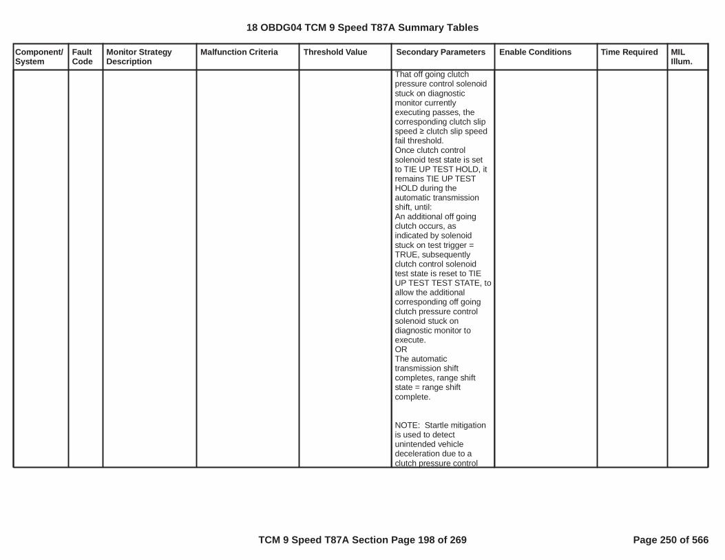
Component/System
FaultCode
Monitor StrategyDescription
Malfunction Criteria Threshold Value Secondary Parameters Enable Conditions Time Required MILIllum.
That off going clutchpressure control solenoidstuck on diagnosticmonitor currentlyexecuting passes, thecorresponding clutch slipspeed clutch slip speedfail threshold.Once clutch controlsolenoid test state is setto TIE UP TEST HOLD, itremains TIE UP TESTHOLD during theautomatic transmissionshift, until:An additional off goingclutch occurs, asindicated by solenoidstuck on test trigger =TRUE, subsequentlyclutch control solenoidtest state is reset to TIEUP TEST TEST STATE, toallow the additionalcorresponding off goingclutch pressure controlsolenoid stuck ondiagnostic monitor toexecute.ORThe automatictransmission shiftcompletes, range shiftstate = range shiftcomplete.
NOTE: Startle mitigationis used to detectunintended vehicledeceleration due to aclutch pressure control
18 OBDG04 TCM 9 Speed T87A Summary Tables
TCM 9 Speed T87A Section Page 198 of 269 Page 250 of 566

Component/System
FaultCode
Monitor StrategyDescription
Malfunction Criteria Threshold Value Secondary Parameters Enable Conditions Time Required MILIllum.
solenoid stuck on failuremode that occurs duringsteady state gear, notduring an automatictransmission shift. Thestartle mitigation activethen forces thetransmission clutchpressure control systemto a safe gear or neutralstate, based on the activeand inactive clutches,when the unintendedvehicle decelerationoccurred. Once a safevehicle gear state isattained, the gear andclutch pressure controlsystem allows transitionsof the clutches on and off,to sequence automatictransmission shifts, singlestep shifts. As eachsingle step automatictransmission shift occursthe normal pressurecontrol solenoid stuck ondiagnostic monitorsexecute to verify whichclutch pressure controlsolenoid is in the stuck onfailure mode, allowing oneof the clutch pressurecontrol solenoid stuck onDTCs to set P0747,P0777, P0797, P2715,P2724, P2733, P2821.
DTCs not fault pending P0716 P0717 P0722P0723 P077C P077DP07BF P07C0
18 OBDG04 TCM 9 Speed T87A Summary Tables
TCM 9 Speed T87A Section Page 199 of 269 Page 251 of 566

Component/System
FaultCode
Monitor StrategyDescription
Malfunction Criteria Threshold Value Secondary Parameters Enable Conditions Time Required MILIllum.
DTCs not test fail this keyon
DTCs not fault active
P0707 P0708 P0746P0747 P0776 P0777P0796 P0797 P2714P2715 P2723 P2724P2732 P2733 P2820P2821
AcceleratorPedalFailureCrankSensor_FAP0707 P0708 P0716P0717 P07BF P07C0P0722 P0723 P077CP077D P172A P172BP176B P176C P176DP17C5 P17CC P17CDP17CE P17D3 P17D6P2805
18 OBDG04 TCM 9 Speed T87A Summary Tables
TCM 9 Speed T87A Section Page 200 of 269 Page 252 of 566

Component/System
FaultCode
Monitor StrategyDescription
Malfunction Criteria Threshold Value Secondary Parameters Enable Conditions Time Required MILIllum.
PressureControl (PC)Solenoid EControlCircuit Open
P2727 Controller specificcircuit diagnoses 9speed C57R or 10speed C1356789 clutchsolenoid for an opencircuit failure bycomparing a voltagemeasurement tocontroller specificvoltage thresholds.
Voltage measurementoutside of controllerspecific acceptable rangeindicates an open circuit
Controller specific circuitvoltage thresholds are setto meet the followingcontroller specification foran open circuit
Increment fail time
200 K impedancebetween signal andcontroller ground
battery voltage
run crank voltageORaccessory voltage active
diagnostic monitor enablecalibration
volts and9.00volts32.00
volts5.00
= TRUE
= Boolean1
seconds1.000
25 milliseconds
12.5 milliseconds
fail time 0.300seconds out ofsample time
seconds0.500
Type A,1 Trips
18 OBDG04 TCM 9 Speed T87A Summary Tables
TCM 9 Speed T87A Section Page 201 of 269 Page 253 of 566
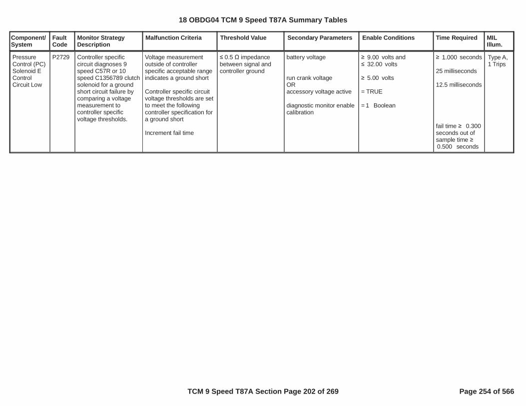
Component/System
FaultCode
Monitor StrategyDescription
Malfunction Criteria Threshold Value Secondary Parameters Enable Conditions Time Required MILIllum.
PressureControl (PC)Solenoid EControlCircuit Low
P2729 Controller specificcircuit diagnoses 9speed C57R or 10speed C1356789 clutchsolenoid for a groundshort circuit failure bycomparing a voltagemeasurement tocontroller specificvoltage thresholds.
Voltage measurementoutside of controllerspecific acceptable rangeindicates a ground short
Controller specific circuitvoltage thresholds are setto meet the followingcontroller specification fora ground short
Increment fail time
0.5 impedancebetween signal andcontroller ground
battery voltage
run crank voltageORaccessory voltage active
diagnostic monitor enablecalibration
volts and9.00volts32.00
volts5.00
= TRUE
= Boolean1
seconds1.000
25 milliseconds
12.5 milliseconds
fail time 0.300seconds out ofsample time
seconds0.500
Type A,1 Trips
18 OBDG04 TCM 9 Speed T87A Summary Tables
TCM 9 Speed T87A Section Page 202 of 269 Page 254 of 566

Component/System
FaultCode
Monitor StrategyDescription
Malfunction Criteria Threshold Value Secondary Parameters Enable Conditions Time Required MILIllum.
PressureControl (PC)Solenoid EControlCircuit High
P2730 Controller specificcircuit diagnoses 9speed C57R or 10speed C1356789 clutchsolenoid for a short tovoltage circuit failure bycomparing a voltagemeasurement tocontroller specificvoltage thresholds.
Voltage measurementoutside of controllerspecific acceptable rangeindicates a short tovoltage
Controller specific circuitvoltage thresholds are setto meet the followingcontroller specification fora short to voltage
Increment fail time
0.5 impedancebetween signal andcontroller voltagesource
battery voltage
run crank voltageORaccessory voltage active
diagnostic monitor enablecalibration
volts and9.00volts32.00
volts5.00
= TRUE
= Boolean1
seconds1.000
25 milliseconds
12.5 milliseconds
fail time 0.300seconds out ofsample time
seconds0.500
Type A,1 Trips
18 OBDG04 TCM 9 Speed T87A Summary Tables
TCM 9 Speed T87A Section Page 203 of 269 Page 255 of 566

Component/System
FaultCode
Monitor StrategyDescription
Malfunction Criteria Threshold Value Secondary Parameters Enable Conditions Time Required MILIllum.
PressureControl (PC)Solenoid FStuck Off
P2732 Each pressure controlsolenoid stuck offdiagnostic monitordetects a clutchpressure controlsolenoid failedhydraulically off, whilethe solenoid iselectrically functional.In the failure mode theclutch slip speed, andgear box gear slip, willbe excessive, not nearor at zero RPM. Theclutch slip speed iscalculated based onthe transmission levernode design, requiringtransmission input shaftspeed, transmissionoutput shaft speed,and, one transmissionintermediate shaftspeed. The clutchpressure controlsolenoid is tested afteran automatictransmission shiftoccurs and has beenconsidered shiftcomplete, or, steadystate gear is deemedactive, range shiftcomplete. When theautomatic transmissionshift is complete,steady state gear isconsidered, the clutchpressure controlsolenoid is mapped totransmission line
C1 clutch slip speed,update fail time6.25 milliscond update
RPM200.0
use battery voltagecalibration is FALSEOR(use battery voltagecalibration is TRUEANDbattery voltage
use run crank voltagecalibration is FALSEOR(use run crank voltagecalibration is TRUEANDrun crank voltage
TCM output driver highside driver 1, clutchpressure control solenoiddriver circuit enabled
TCM output driver highside driver 2, clutchpressure control solenoiddriver circuit enabled
service fast learn activeservice solenoid cleaningprocedure active
hydraulic pressure
= Boolean1
= Boolean1
volts9.00
= Boolean0
= Boolean0
volts9.00
= TRUE Boolean
= TRUE Boolean
= FALSE Boolean= FALSE Boolean
fail time 3.00seconds,update fail count,fail count 3counts6.25 milliscondupdate
battery voltagetime 0.100seconds
run crank voltagetime 0.100seconds
Type A,1 Trips
18 OBDG04 TCM 9 Speed T87A Summary Tables
TCM 9 Speed T87A Section Page 204 of 269 Page 256 of 566

Component/System
FaultCode
Monitor StrategyDescription
Malfunction Criteria Threshold Value Secondary Parameters Enable Conditions Time Required MILIllum.
pressure control, whichnormally allows theclutch to maintain fulltorque holding capacityat the given enginecrankshaft torque, tomaintain true gearratio. When the clutchpressure controlsolenoid is failedhydraulically off, theclutch does notmaintain holdingcapacity at any enginecrankshaft torque, andthe clutch slip speed isuncontrollable. Theclutch pressure controlsolenoid test issuspended if the higherlevel safety startlemitigation function isactive. The safetystartle mitigationfunction is triggeredwhen a sudden vehicledeceleration occursdue to a clutchpressure controlsolenoid that has failedin the opposite sense,clutch pressure controlsolenoid failedhydraulically on, whilethe solenoid iselectrically functional,which must take priorityover any clutchpressure controlsolenoid stuck offdiagnostic monitor. Allclutch pressure control
available:engine speed
enable C6 clutch slipspeed fail compare when:diagnostic clutch test C6((startle mitigation activeOR(startle mitigation activeANDstartle mitigation gear))(see startle mitigationactive NOTE below)unintended decelerationfault pending ORunintended decelerationfault pending enableFASLE(startle mitigation)clutch steady stateadaptive activetransmission output shaftspeedC6 clutch slip speed valid,all speed sesnors arefunctional for lever nodeclucth slip speedcalculation
accelerator pedal positionengine speed
diagnostic clutch test C6set to HOLDING CLUTCHwhen:clutch solenoid test state
RPM400.0
= HOLDING CLUTCH= FALSE
= TRUE
initial startle mitigationgear
= FALSE
= Boolean0
= FALSE
RPM89.0
= TRUE
%2.00RPM1,500.0
= NEUTRAL TEST
engine speedtime engine speedtime fortransmissionhydraulicpressureavailablesee supportingtable
18 OBDG04 TCM 9 Speed T87A Summary Tables
TCM 9 Speed T87A Section Page 205 of 269 Page 257 of 566

Component/System
FaultCode
Monitor StrategyDescription
Malfunction Criteria Threshold Value Secondary Parameters Enable Conditions Time Required MILIllum.
solenoid stuck on/offdiagnostic monitors areemission MIL DTCs.System voltage mustbe normal, all clutchpressure controlsolenoid driver circuitsmust be functional, noclutch pressure controlsolenoid electrical orperformance faults canbe present, and nospeed sensor electricalor performance faultscan be present, or thea clutch pressurecontrol solenoid stuckoff test is disabled.This diagnostic monitoris relative to the GF9C6 C6789/SelectableOne Way Clutch(SOWC) CBR1, or,GR10 C6C45678910R, clutchpressure controlsolenoid.
((startle mitigation activeOR(startle mitigation activeANDstartle mitigation gear))(see startle mitigationactive NOTE below)C6 clutch pressured map
clutch solenoid test stateset to NEUTRAL TESTwhen:test triggerinitialize range shiftcomplete time,whenrange shift state,range shift complete timemust time down to zerowhenrange shift complete
test trigger set to TRUE:enable forward gear ANDdirection requestORenable reverse gear ANDdirection requestcurrent loop test triggerclutch control solenoidtest staterange shift state
NOTE: startle mitigationactive is used to detectunintended decelerationdue to clutch pressurecontrol solenoid stuck on
= FALSE
= TRUE
initial startle mitigationgear
= mapped to linepressure, C6 clutchpressure has transtionedfrom off-applying-applied
= TRUE
range shift completed
= Boolean1= forward gear
= Boolean0= reverse gear= FALSE NEUTRAL TEST
= range shift completed
initialize rangeshift completetime = 1.000seconds,range shiftcomplete timemust time downto zerowhenrange shiftcomplete
18 OBDG04 TCM 9 Speed T87A Summary Tables
TCM 9 Speed T87A Section Page 206 of 269 Page 258 of 566

Component/System
FaultCode
Monitor StrategyDescription
Malfunction Criteria Threshold Value Secondary Parameters Enable Conditions Time Required MILIllum.
failure modes, the clutchpressure control solenoidstuck on DTCs beingP0747 P0777 P0797P2715 P2724 P2733P2821
DTCs not fault pending
DTCs not test fail this keyon
DTCs not fault active
P0716 P0717 P0722P0723 P077C P077DP07BF P07C0
P0707 P0708 P0746P0747 P0776 P0777P0796 P0797 P2714P2715 P2723 P2724P2732 P2733 P2820P2821
AcceleratorPedalFailureCrankSensor_FAP0707 P0708 P0716P0717 P07BF P07C0P0722 P0723 P077CP077D P172A P172BP176B P176C P176DP17C5 P17CC P17CDP17CE P17D3 P17D6P2805
18 OBDG04 TCM 9 Speed T87A Summary Tables
TCM 9 Speed T87A Section Page 207 of 269 Page 259 of 566

Component/System
FaultCode
Monitor StrategyDescription
Malfunction Criteria Threshold Value Secondary Parameters Enable Conditions Time Required MILIllum.
PressureControl (PC)Solenoid FStuck On
P2733 Each pressure controlsolenoid stuck ondiagnostic monitordetects a clutchpressure controlsolenoid failedhydraulically on, whilethe solenoid iselectrically functional.The clutch pressurecontrol solenoid istested during anautomatic transmissionshift by monitoring theoff going clutch slipspeed. With the clutchpressure controlsolenoid failed on, stillallowing hydraulicpressure to the clutchbeing commanded off,the intended off goingclutch continues tomaintain torquecapacity during thetransmission automaticshift. In the failuremode, the off goingclutch slip speed willremain near zero RPMwhen the clutchpressure controlsolenoid is commandedto an off pressure in thenormal operation torelease the holdingclutch. The clutch slipspeed is calculatedbased on thetransmission levernode design, requiring
shift type is power downshift,C6 clutch slip speedORshift type is not powerdown shift,C6 clutch slip speed
update fail time6.25 milliscond update
< RPM50.0
< RPM50.0
use battery voltagecalibration is FALSEOR(use battery voltagecalibration is TRUEANDbattery voltage
use run crank voltagecalibration is FALSEOR(use run crank voltagecalibration is TRUEANDrun crank voltage
TCM output driver highside driver 1, clutchpressure control solenoiddriver circuit enabled
= Boolean1
= Boolean1
volts9.00
= Boolean0
= Boolean0
volts9.00
= TRUE Boolean
shift type ispower downshift,fail time 0.800seconds,ORshift type is notpower downshift,fail time 0.150seconds,
update fail count,fail count 3counts6.25 milliscondupdate
battery voltagetime 0.100seconds
run crank voltagetime 0.100seconds
Type A,1 Trips
18 OBDG04 TCM 9 Speed T87A Summary Tables
TCM 9 Speed T87A Section Page 208 of 269 Page 260 of 566

Component/System
FaultCode
Monitor StrategyDescription
Malfunction Criteria Threshold Value Secondary Parameters Enable Conditions Time Required MILIllum.
transmission input shaftspeed, transmissionoutput shaft speed,and, one transmissionintermediate shaftspeed. As part of thepressure controlsolenoid stuck ondiagnostic monitor, thesafety startle mitigationfunction executes whenin steady state gear, noautomatic transmissionshift in progress. Thesafety startle mitigationfunction is triggeredwhen a sudden vehicledeceleration occursdue to a clutchpressure controlsolenoid that has failedhydraulically on, whilethe solenoid iselectrically functional.All clutch pressurecontrol solenoid stuckon diagnostic monitorsare emission MILDTCs. System voltagemust be normal, allclutch pressure controlsolenoid driver circuitsmust be functional, noclutch pressure controlsolenoid electrical orperformance faults canbe present, and nospeed sensor electricalor performance faultscan be present, or thea clutch pressurecontrol solenoid stuck
TCM output driver highside driver 2, clutchpressure control solenoiddriver circuit enabled
service fast learn activeservice solenoid cleaningprocedure active
hydraulic pressureavailable:engine speed
transmission output shaftspeed
set solenoid stuck on testtrigger to TRUE when:clutch pressure controlsolenoid stuck off stuckintrusive shift requeststartle mitigation active(see startle mitigationactive NOTE below)clutch control solenoidtest stateclutch control solenoidtest state (see clutchcontrol solenoid test stateNOTE below)initialize active clutchcontroller (clutch controlprocessing in process ofsequencing clutches on
= TRUE Boolean
= FALSE Boolean= FALSE Boolean
RPM400.0
RPM89.0
= FALSE
= FALSE
TIE UP TEST TESTSTATE TIE UP TEST HOLD
= TRUE
engine speedtime engine speedtime fortransmissionhydraulicpressureavailablesee supportingtable
18 OBDG04 TCM 9 Speed T87A Summary Tables
TCM 9 Speed T87A Section Page 209 of 269 Page 261 of 566

Component/System
FaultCode
Monitor StrategyDescription
Malfunction Criteria Threshold Value Secondary Parameters Enable Conditions Time Required MILIllum.
on test is disabled. Thisdiagnostic monitor isrelative to the GF9 C6C6789/Selectable OneWay Clutch (SOWC)CBR1, or, GR10 C6C45678910R, clutchpressure controlsolenoid.
and off for auto trans shift)(shift type enable forstaged steady state shift -shift in process when newshift type occurs -interrupted shiftORshift type enable forgarage shiftORshift type enable fornegative torque up shiftORshift type enable for openthrottle power on up shiftORshift type enable forclosed throttle down shiftORshift type enable for openthrottle power down shiftORshift type enable forclosed throttle lift foot upshift )ORclutch control solenoidtest stateclutch control solenoidtest state (see clutchcontrol solenoid test stateNOTE below)transition clutch controlleractive clutch controller(staged steady sate shift -shift not in process, nonew shift type occuring,no interrupted shift)
set clutch control solenoidtest state to TIE UP TEST
= Boolean0
= Boolean0
= Boolean1
= Boolean1
= Boolean1
= Boolean1
= Boolean0
= TIE UP TEST TESTSTATE= TIE UP TEST HOLD
= TRUE staged steady state
18 OBDG04 TCM 9 Speed T87A Summary Tables
TCM 9 Speed T87A Section Page 210 of 269 Page 262 of 566

Component/System
FaultCode
Monitor StrategyDescription
Malfunction Criteria Threshold Value Secondary Parameters Enable Conditions Time Required MILIllum.
TEST STATE when:solenoid stuck on testtriggercurrent loop clutch controlsolenoid test stateORcurrent loop clutch controlsolenoid test state (seeclutch control solenoidtest state NOTE below)range shift statesolenoid stuck on testtriggeradditional off going clutchoccured
(clutch control solenoidtest state ORclutch control solenoidtest state) (see clutchcontrol solenoid test stateNOTE below)diagnostic clutch test
(C6 off going clutchpressure control ramptime out complete ANDoff going clutch pressureramp control ramp timeout enable)ORC6 off going clutchpressure
= TRUE
= TEST WAITING
= TIE UP TEST HOLD
range shift complete= TRUE
= TRUE
= TIE UP TEST TESTSTATE= TIE UP TEST HOLD
= OFF GOING CLUTCHTEST= TRUE
= Boolean1
kPa350.0 for C6 off goingclutch pressuretime P2733 C6 clutchexhaust delaytime closedthrottle lift footup shiftOR
18 OBDG04 TCM 9 Speed T87A Summary Tables
TCM 9 Speed T87A Section Page 211 of 269 Page 263 of 566

Component/System
FaultCode
Monitor StrategyDescription
Malfunction Criteria Threshold Value Secondary Parameters Enable Conditions Time Required MILIllum.
engine torqueprimary on coming clutchactiveprimary on coming controlstateclosed throttle lift foot upshift primary on comingclutch pressureORopen throttle power on upshift primary on comingclutch pressureORgarage shift primary on
Nm8,191.8= TRUE
clutch fill phase
kPa655.0
kPA655.0
kPa750.0
P2733 C6 clutchexhaust delaytime openthrottle poweron up shiftORP2733 C6 clutchexhaust delaytime garageshiftORP2733 C6 clutchexhaust delaytime closedthrottle downshiftORP2733 C6 clutchexhaust delaytime negativetorque up shiftORP2733 C6 clutchexhaust delaytime openthrottle powerdown shiftsee supportingtables
18 OBDG04 TCM 9 Speed T87A Summary Tables
TCM 9 Speed T87A Section Page 212 of 269 Page 264 of 566

Component/System
FaultCode
Monitor StrategyDescription
Malfunction Criteria Threshold Value Secondary Parameters Enable Conditions Time Required MILIllum.
coming clutch pressureORnegative torque up shiftprimary on coming clutchpressureORopen throttle power downshift primary on comingclutch pressureORclosed throttle down shiftprimary on coming clutchpressureC6 clutch slip speed valid,all speed sesnors arefunctional for lever nodeclucth slip speedcalculation
NOTE: Clutch controlsolenoid test state TIE UPTEST HOLD is necessary,as it is possible to havemultiple off going clutchesduring one automatictransmission shift. Clutchcontrol solenoid test stateis set to TIE UP TESTHOLD during anautomatic transmissionshift due to twoconditions:Current value of clutchcontrol solenoid test stateis TIE UP TEST TESTSTATE, when one offgoing clutch pressurecontrol solenoid stuck ondiagnostic monitor iscurrently executing.AND
kPa655.0
kPa655.0
kPa655.0
= TRUE
18 OBDG04 TCM 9 Speed T87A Summary Tables
TCM 9 Speed T87A Section Page 213 of 269 Page 265 of 566

Component/System
FaultCode
Monitor StrategyDescription
Malfunction Criteria Threshold Value Secondary Parameters Enable Conditions Time Required MILIllum.
That off going clutchpressure control solenoidstuck on diagnosticmonitor currentlyexecuting passes, thecorresponding clutch slipspeed clutch slip speedfail threshold.Once clutch controlsolenoid test state is setto TIE UP TEST HOLD, itremains TIE UP TESTHOLD during theautomatic transmissionshift, until:An additional off goingclutch occurs, asindicated by solenoidstuck on test trigger =TRUE, subsequentlyclutch control solenoidtest state is reset to TIEUP TEST TEST STATE, toallow the additionalcorresponding off goingclutch pressure controlsolenoid stuck ondiagnostic monitor toexecute.ORThe automatictransmission shiftcompletes, range shiftstate = range shiftcomplete.
NOTE: Startle mitigationis used to detectunintended vehicledeceleration due to aclutch pressure control
18 OBDG04 TCM 9 Speed T87A Summary Tables
TCM 9 Speed T87A Section Page 214 of 269 Page 266 of 566
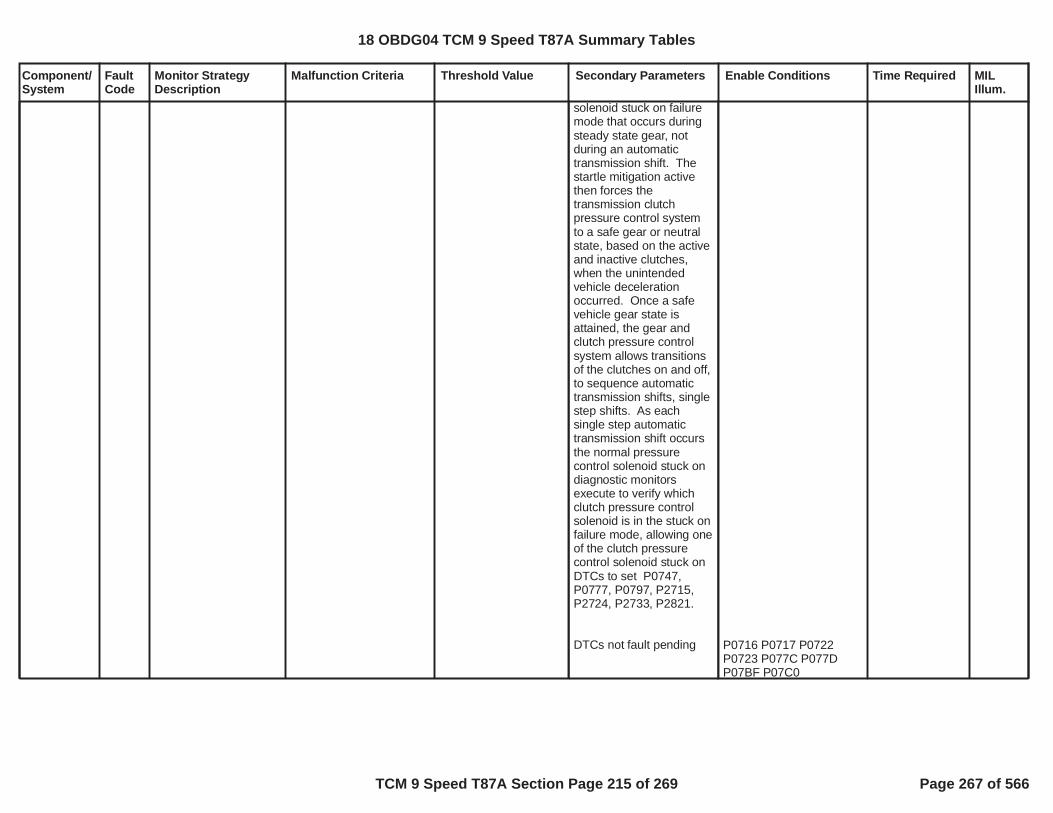
Component/System
FaultCode
Monitor StrategyDescription
Malfunction Criteria Threshold Value Secondary Parameters Enable Conditions Time Required MILIllum.
solenoid stuck on failuremode that occurs duringsteady state gear, notduring an automatictransmission shift. Thestartle mitigation activethen forces thetransmission clutchpressure control systemto a safe gear or neutralstate, based on the activeand inactive clutches,when the unintendedvehicle decelerationoccurred. Once a safevehicle gear state isattained, the gear andclutch pressure controlsystem allows transitionsof the clutches on and off,to sequence automatictransmission shifts, singlestep shifts. As eachsingle step automatictransmission shift occursthe normal pressurecontrol solenoid stuck ondiagnostic monitorsexecute to verify whichclutch pressure controlsolenoid is in the stuck onfailure mode, allowing oneof the clutch pressurecontrol solenoid stuck onDTCs to set P0747,P0777, P0797, P2715,P2724, P2733, P2821.
DTCs not fault pending P0716 P0717 P0722P0723 P077C P077DP07BF P07C0
18 OBDG04 TCM 9 Speed T87A Summary Tables
TCM 9 Speed T87A Section Page 215 of 269 Page 267 of 566

Component/System
FaultCode
Monitor StrategyDescription
Malfunction Criteria Threshold Value Secondary Parameters Enable Conditions Time Required MILIllum.
DTCs not test fail this keyon
DTCs not fault active
P0707 P0708 P0746P0747 P0776 P0777P0796 P0797 P2714P2715 P2723 P2724P2732 P2733 P2820P2821
AcceleratorPedalFailureCrankSensor_FAP0707 P0708 P0716P0717 P07BF P07C0P0722 P0723 P077CP077D P172A P172BP176B P176C P176DP17C5 P17CC P17CDP17CE P17D3 P17D6P2805
18 OBDG04 TCM 9 Speed T87A Summary Tables
TCM 9 Speed T87A Section Page 216 of 269 Page 268 of 566

Component/System
FaultCode
Monitor StrategyDescription
Malfunction Criteria Threshold Value Secondary Parameters Enable Conditions Time Required MILIllum.
PressureControl (PC)Solenoid FControlCircuit Open
P2736 Controller specificcircuit diagnoses 9speed C6789 or 10speed C45678910Rclutch solenoid for anopen circuit failure bycomparing a voltagemeasurement tocontroller specificvoltage thresholds.
Voltage measurementoutside of controllerspecific acceptable rangeindicates an open circuit
Controller specific circuitvoltage thresholds are setto meet the followingcontroller specification foran open circuit
Increment fail time
200 K impedancebetween signal andcontroller ground
battery voltage
run crank voltageORaccessory voltage active
diagnostic monitor enablecalibration
volts and9.00volts32.00
volts5.00
= TRUE
= Boolean1
seconds1.000
25 milliseconds
12.5 milliseconds
fail time 0.300seconds out ofsample time
seconds0.500
Type A,1 Trips
18 OBDG04 TCM 9 Speed T87A Summary Tables
TCM 9 Speed T87A Section Page 217 of 269 Page 269 of 566

Component/System
FaultCode
Monitor StrategyDescription
Malfunction Criteria Threshold Value Secondary Parameters Enable Conditions Time Required MILIllum.
PressureControl (PC)Solenoid FControlCircuit Low
P2738 Controller specificcircuit diagnoses 9speed C6789 or 10speed C45678910Rclutch solenoid for aground short circuitfailure by comparing avoltage measurementto controller specificvoltage thresholds.
Voltage measurementoutside of controllerspecific acceptable rangeindicates a ground short
Controller specific circuitvoltage thresholds are setto meet the followingcontroller specification fora ground short
Increment fail time
0.5 impedancebetween signal andcontroller ground
battery voltage
run crank voltageORaccessory voltage active
diagnostic monitor enablecalibration
volts and9.00volts32.00
volts5.00
= TRUE
= Boolean1
seconds1.000
25 milliseconds
12.5 milliseconds
fail time 0.300seconds out ofsample time
seconds0.500
Type A,1 Trips
18 OBDG04 TCM 9 Speed T87A Summary Tables
TCM 9 Speed T87A Section Page 218 of 269 Page 270 of 566

Component/System
FaultCode
Monitor StrategyDescription
Malfunction Criteria Threshold Value Secondary Parameters Enable Conditions Time Required MILIllum.
PressureControl (PC)Solenoid FControlCircuit High
P2739 Controller specificcircuit diagnoses 9speed C6789 or 10speed C45678910Rclutch solenoid for ashort to voltage circuitfailure by comparing avoltage measurementto controller specificvoltage thresholds.
Voltage measurementoutside of controllerspecific acceptable rangeindicates a short tovoltage
Controller specific circuitvoltage thresholds are setto meet the followingcontroller specification fora short to voltage
Increment fail time
0.5 impedancebetween signal andcontroller voltagesource
battery voltage
run crank voltageORaccessory voltage active
diagnostic monitor enablecalibration
volts and9.00volts32.00
volts5.00
= TRUE
= Boolean1
seconds1.000
25 milliseconds
12.5 milliseconds
fail time 0.300seconds out ofsample time
seconds0.500
Type A,1 Trips
18 OBDG04 TCM 9 Speed T87A Summary Tables
TCM 9 Speed T87A Section Page 219 of 269 Page 271 of 566

Component/System
FaultCode
Monitor StrategyDescription
Malfunction Criteria Threshold Value Secondary Parameters Enable Conditions Time Required MILIllum.
PressureControl (PC)Solenoid ACalibrationIncorrect
P27A7 The diagnostic monitorverifies that thepressure controlsolenoid A (GF9 linepressure or GR10 C1C123456R clutch)characterization data isprogrammed correctlyinto the TCM EEPROMto match the pressurecontrol solenoid Aelectricalcharacteristics of thedevice currentlyinstalled in thetransmission valvebody assembly.
pressure control solenoidcharacterization dataprogramming complete
Matching is defined aspressure control solenoidcharacterization datacorresponding to thetransmission valve bodyassembly componentry.
pressure control solenoidcharacterization dataprogramming complete isset to FALSE when any ofthe following is present:
Solenoid data is notprogrammed orincomplete data fault -occurs when a new orservice TCM is installed.ORSolenoid classprogramming fault – thecharacterization dataindicates a different typeof device than the TCMcalibration dataORChecksum mismatch –the checksum that wascalculated from theprogrammed pressurecontrol solenoidcharacterization dataregion does not match thecalculated valve at thetime of programming.ORAxis data fault – pressure
= FALSE Pressure control solenoidcharacterization data isprogrammed originally atvehicle plant assemblybased on transmissionvalve body assembly partnumber associated to theunit installed in vehicle.
When valve body isserviced, dealershipperforms reprogrammingof TCM with pressurecontrol solenoidcharacterization databased on the associatedtransmission valve bodypart number installed.
execution ofmonitor occursonce percontroller normalpower up eventduring thecontrollerinitializationbefore normalcontroller timeloop execution
Type A,1 Trips
18 OBDG04 TCM 9 Speed T87A Summary Tables
TCM 9 Speed T87A Section Page 220 of 269 Page 272 of 566

Component/System
FaultCode
Monitor StrategyDescription
Malfunction Criteria Threshold Value Secondary Parameters Enable Conditions Time Required MILIllum.
control solenoidcharacterization data hasone or more points thatare less than the previousmatch point, axis datamust be greater than orequal to previous datavalues.
18 OBDG04 TCM 9 Speed T87A Summary Tables
TCM 9 Speed T87A Section Page 221 of 269 Page 273 of 566

Component/System
FaultCode
Monitor StrategyDescription
Malfunction Criteria Threshold Value Secondary Parameters Enable Conditions Time Required MILIllum.
PressureControl (PC)Solenoid BCalibrationIncorrect
P27A8 The diagnostic monitorverifies that thepressure controlsolenoid B (GF9 TCCpressure or GR10 C2C128910R clutch)characterization data isprogrammed correctlyinto the TCM EEPROMto match the pressurecontrol solenoid Belectricalcharacteristics of thedevice currentlyinstalled in thetransmission valvebody assembly.
pressure control solenoidcharacterization dataprogramming complete
Matching is defined aspressure control solenoidcharacterization datacorresponding to thetransmission valve bodyassembly componentry.
pressure control solenoidcharacterization dataprogramming complete isset to FALSE when any ofthe following is present:
Solenoid data is notprogrammed orincomplete data fault -occurs when a new orservice TCM is installed.ORSolenoid classprogramming fault – thecharacterization dataindicates a different typeof device than the TCMcalibration dataORChecksum mismatch –the checksum that wascalculated from theprogrammed pressurecontrol solenoidcharacterization dataregion does not match thecalculated valve at thetime of programming.ORAxis data fault – pressure
= FALSE Pressure control solenoidcharacterization data isprogrammed originally atvehicle plant assemblybased on transmissionvalve body assembly partnumber associated to theunit installed in vehicle.
When valve body isserviced, dealershipperforms reprogrammingof TCM with pressurecontrol solenoidcharacterization databased on the associatedtransmission valve bodypart number installed.
execution ofmonitor occursonce percontroller normalpower eventduring thecontrollerinitializationbefore normaltime loopexecution
Type A,1 Trips
18 OBDG04 TCM 9 Speed T87A Summary Tables
TCM 9 Speed T87A Section Page 222 of 269 Page 274 of 566

Component/System
FaultCode
Monitor StrategyDescription
Malfunction Criteria Threshold Value Secondary Parameters Enable Conditions Time Required MILIllum.
control solenoidcharacterization data hasone or more points thatare less than the previousmatch point, axis datamust be greater than orequal to previous datavalues.
18 OBDG04 TCM 9 Speed T87A Summary Tables
TCM 9 Speed T87A Section Page 223 of 269 Page 275 of 566

Component/System
FaultCode
Monitor StrategyDescription
Malfunction Criteria Threshold Value Secondary Parameters Enable Conditions Time Required MILIllum.
PressureControl (PC)Solenoid CCalibrationIncorrect
P27A9 The diagnostic monitorverifies that thepressure controlsolenoid C (GF9 C1CB123456 clutch orGR10 C3 C23457910clutch) characterizationdata is programmedcorrectly into the TCMEEPROM to match thepressure controlsolenoid C electricalcharacteristics of thedevice currentlyinstalled in thetransmission valvebody assembly.
pressure control solenoidcharacterization dataprogramming complete
Matching is defined aspressure control solenoidcharacterization datacorresponding to thetransmission valve bodyassembly componentry.
pressure control solenoidcharacterization dataprogramming complete isset to FALSE when any ofthe following is present:
Solenoid data is notprogrammed orincomplete data fault -occurs when a new orservice TCM is installed.ORSolenoid classprogramming fault – thecharacterization dataindicates a different typeof device than the TCMcalibration dataORChecksum mismatch –the checksum that wascalculated from theprogrammed pressurecontrol solenoidcharacterization dataregion does not match thecalculated valve at thetime of programming.ORAxis data fault – pressure
= FALSE Pressure control solenoidcharacterization data isprogrammed originally atvehicle plant assemblybased on transmissionvalve body assembly partnumber associated to theunit installed in vehicle.
When valve body isserviced, dealershipperforms reprogrammingof TCM with pressurecontrol solenoidcharacterization databased on the associatedtransmission valve bodypart number installed.
execution ofmonitor occursonce percontroller normalpower up eventduring thecontrollerinitializationbefore normalcontroller timeloop execution
Type A,1 Trips
18 OBDG04 TCM 9 Speed T87A Summary Tables
TCM 9 Speed T87A Section Page 224 of 269 Page 276 of 566

Component/System
FaultCode
Monitor StrategyDescription
Malfunction Criteria Threshold Value Secondary Parameters Enable Conditions Time Required MILIllum.
control solenoidcharacterization data hasone or more points thatare less than the previousmatch point, axis datamust be greater than orequal to previous datavalues.
18 OBDG04 TCM 9 Speed T87A Summary Tables
TCM 9 Speed T87A Section Page 225 of 269 Page 277 of 566

Component/System
FaultCode
Monitor StrategyDescription
Malfunction Criteria Threshold Value Secondary Parameters Enable Conditions Time Required MILIllum.
PressureControl (PC)Solenoid DCalibrationIncorrect
P27AA The diagnostic monitorverifies that thepressure controlsolenoid D (GF9 C2CB29 clutch or GR10C5 C1356789 clutch)characterization data isprogrammed correctlyinto the TCM EEPROMto match the pressurecontrol solenoid Delectricalcharacteristics of thedevice currentlyinstalled in thetransmission valvebody assembly.
pressure control solenoidcharacterization dataprogramming complete
Matching is defined aspressure control solenoidcharacterization datacorresponding to thetransmission valve bodyassembly componentry.
pressure control solenoidcharacterization dataprogramming complete isset to FALSE when any ofthe following is present:
Solenoid data is notprogrammed orincomplete data fault -occurs when a new orservice TCM is installed.ORSolenoid classprogramming fault – thecharacterization dataindicates a different typeof device than the TCMcalibration dataORChecksum mismatch –the checksum that wascalculated from theprogrammed pressurecontrol solenoidcharacterization dataregion does not match thecalculated valve at thetime of programming.ORAxis data fault – pressure
= FALSE Pressure control solenoidcharacterization data isprogrammed originally atvehicle plant assemblybased on transmissionvalve body assembly partnumber associated to theunit installed in vehicle.
When valve body isserviced, dealershipperforms reprogrammingof TCM with pressurecontrol solenoidcharacterization databased on the associatedtransmission valve bodypart number installed.
execution ofmonitor occursonce percontroller normalpower up eventduring thecontrollerinitializationbefore normalcontroller timeloop execution
Type A,1 Trips
18 OBDG04 TCM 9 Speed T87A Summary Tables
TCM 9 Speed T87A Section Page 226 of 269 Page 278 of 566

Component/System
FaultCode
Monitor StrategyDescription
Malfunction Criteria Threshold Value Secondary Parameters Enable Conditions Time Required MILIllum.
control solenoidcharacterization data hasone or more points thatare less than the previousmatch point, axis datamust be greater than orequal to previous datavalues.
18 OBDG04 TCM 9 Speed T87A Summary Tables
TCM 9 Speed T87A Section Page 227 of 269 Page 279 of 566

Component/System
FaultCode
Monitor StrategyDescription
Malfunction Criteria Threshold Value Secondary Parameters Enable Conditions Time Required MILIllum.
PressureControl (PC)Solenoid ECalibrationIncorrect
P27AB The diagnostic monitorverifies that thepressure controlsolenoid E (GF9 C3CB38 clutch or GR10C4 C23467810Rclutch) characterizationdata is programmedcorrectly into the TCMEEPROM to match thepressure controlsolenoid E electricalcharacteristics of thedevice currentlyinstalled in thetransmission valvebody assembly.
pressure control solenoidcharacterization dataprogramming complete
Matching is defined aspressure control solenoidcharacterization datacorresponding to thetransmission valve bodyassembly componentry.
pressure control solenoidcharacterization dataprogramming complete isset to FALSE when any ofthe following is present:
Solenoid data is notprogrammed orincomplete data fault -occurs when a new orservice TCM is installed.ORSolenoid classprogramming fault – thecharacterization dataindicates a different typeof device than the TCMcalibration dataORChecksum mismatch –the checksum that wascalculated from theprogrammed pressurecontrol solenoidcharacterization dataregion does not match thecalculated valve at thetime of programming.ORAxis data fault – pressure
= FALSE Pressure control solenoidcharacterization data isprogrammed originally atvehicle plant assemblybased on transmissionvalve body assembly partnumber associated to theunit installed in vehicle.
When valve body isserviced, dealershipperforms reprogrammingof TCM with pressurecontrol solenoidcharacterization databased on the associatedtransmission valve bodypart number installed.
execution ofmonitor occursonce percontroller normalpower up eventduring thecontrollerinitializationbefore normalcontroller timeloop execution
Type A,1 Trips
18 OBDG04 TCM 9 Speed T87A Summary Tables
TCM 9 Speed T87A Section Page 228 of 269 Page 280 of 566

Component/System
FaultCode
Monitor StrategyDescription
Malfunction Criteria Threshold Value Secondary Parameters Enable Conditions Time Required MILIllum.
control solenoidcharacterization data hasone or more points thatare less than the previousmatch point, axis datamust be greater than orequal to previous datavalues.
18 OBDG04 TCM 9 Speed T87A Summary Tables
TCM 9 Speed T87A Section Page 229 of 269 Page 281 of 566

Component/System
FaultCode
Monitor StrategyDescription
Malfunction Criteria Threshold Value Secondary Parameters Enable Conditions Time Required MILIllum.
PressureControl (PC)Solenoid FCalibrationIncorrect
P27AC The diagnostic monitorverifies that thepressure controlsolenoid F (GF9 C4 C4clutch or GR10 C6C45678910R clutch)characterization data isprogrammed correctlyinto the TCM EEPROMto match the pressurecontrol solenoid Felectricalcharacteristics of thedevice currentlyinstalled in thetransmission valvebody assembly.
pressure control solenoidcharacterization dataprogramming complete
Matching is defined aspressure control solenoidcharacterization datacorresponding to thetransmission valve bodyassembly componentry.
pressure control solenoidcharacterization dataprogramming complete isset to FALSE when any ofthe following is present:
Solenoid data is notprogrammed orincomplete data fault -occurs when a new orservice TCM is installed.ORSolenoid classprogramming fault – thecharacterization dataindicates a different typeof device than the TCMcalibration dataORChecksum mismatch –the checksum that wascalculated from theprogrammed pressurecontrol solenoidcharacterization dataregion does not match thecalculated valve at thetime of programming.ORAxis data fault – pressure
= FALSE Pressure control solenoidcharacterization data isprogrammed originally atvehicle plant assemblybased on transmissionvalve body assembly partnumber associated to theunit installed in vehicle.
When valve body isserviced, dealershipperforms reprogrammingof TCM with pressurecontrol solenoidcharacterization databased on the associatedtransmission valve bodypart number installed.
execution ofmonitor occursonce percontroller normalpower up eventduring thecontrollerinitializationbefore normalcontroller timeloop execution
Type A,1 Trips
18 OBDG04 TCM 9 Speed T87A Summary Tables
TCM 9 Speed T87A Section Page 230 of 269 Page 282 of 566

Component/System
FaultCode
Monitor StrategyDescription
Malfunction Criteria Threshold Value Secondary Parameters Enable Conditions Time Required MILIllum.
control solenoidcharacterization data hasone or more points thatare less than the previousmatch point, axis datamust be greater than orequal to previous datavalues.
18 OBDG04 TCM 9 Speed T87A Summary Tables
TCM 9 Speed T87A Section Page 231 of 269 Page 283 of 566

Component/System
FaultCode
Monitor StrategyDescription
Malfunction Criteria Threshold Value Secondary Parameters Enable Conditions Time Required MILIllum.
PressureControl (PC)Solenoid GCalibrationIncorrect
P27AD The diagnostic monitorverifies that thepressure controlsolenoid G (GF9 C5C57R clutch or GR10line pressure)characterization data isprogrammed correctlyinto the TCM EEPROMto match the pressurecontrol solenoid Gelectricalcharacteristics of thedevice currentlyinstalled in thetransmission valvebody assembly.
pressure control solenoidcharacterization dataprogramming complete
Matching is defined aspressure control solenoidcharacterization datacorresponding to thetransmission valve bodyassembly componentry.
pressure control solenoidcharacterization dataprogramming complete isset to FALSE when any ofthe following is present:
Solenoid data is notprogrammed orincomplete data fault -occurs when a new orservice TCM is installed.ORSolenoid classprogramming fault – thecharacterization dataindicates a different typeof device than the TCMcalibration dataORChecksum mismatch –the checksum that wascalculated from theprogrammed pressurecontrol solenoidcharacterization dataregion does not match thecalculated valve at thetime of programming.ORAxis data fault – pressure
= FALSE Pressure control solenoidcharacterization data isprogrammed originally atvehicle plant assemblybased on transmissionvalve body assembly partnumber associated to theunit installed in vehicle.
When valve body isserviced, dealershipperforms reprogrammingof TCM with pressurecontrol solenoidcharacterization databased on the associatedtransmission valve bodypart number installed.
execution ofmonitor occursonce percontroller normalpower up eventduring thecontrollerinitializationbefore normalcontroller timeloop execution
Type A,1 Trips
18 OBDG04 TCM 9 Speed T87A Summary Tables
TCM 9 Speed T87A Section Page 232 of 269 Page 284 of 566

Component/System
FaultCode
Monitor StrategyDescription
Malfunction Criteria Threshold Value Secondary Parameters Enable Conditions Time Required MILIllum.
control solenoidcharacterization data hasone or more points thatare less than the previousmatch point, axis datamust be greater than orequal to previous datavalues.
18 OBDG04 TCM 9 Speed T87A Summary Tables
TCM 9 Speed T87A Section Page 233 of 269 Page 285 of 566

Component/System
FaultCode
Monitor StrategyDescription
Malfunction Criteria Threshold Value Secondary Parameters Enable Conditions Time Required MILIllum.
PressureControl (PC)Solenoid HCalibrationIncorrect
P27AE The diagnostic monitorverifies that thepressure controlsolenoid H (GF9 C6C6789 clutch or GR10TCC) characterizationdata is programmedcorrectly into the TCMEEPROM to match thepressure controlsolenoid H electricalcharacteristics of thedevice currentlyinstalled in thetransmission valvebody assembly.
pressure control solenoidcharacterization dataprogramming complete
Matching is defined aspressure control solenoidcharacterization datacorresponding to thetransmission valve bodyassembly componentry.
pressure control solenoidcharacterization dataprogramming complete isset to FALSE when any ofthe following is present:
Solenoid data is notprogrammed orincomplete data fault -occurs when a new orservice TCM is installed.ORSolenoid classprogramming fault – thecharacterization dataindicates a different typeof device than the TCMcalibration dataORChecksum mismatch –the checksum that wascalculated from theprogrammed pressurecontrol solenoidcharacterization dataregion does not match thecalculated valve at thetime of programming.ORAxis data fault – pressure
= FALSE Pressure control solenoidcharacterization data isprogrammed originally atvehicle plant assemblybased on transmissionvalve body assembly partnumber associated to theunit installed in vehicle.
When valve body isserviced, dealershipperforms reprogrammingof TCM with pressurecontrol solenoidcharacterization databased on the associatedtransmission valve bodypart number installed.
execution ofmonitor occursonce percontroller normalpower up eventduring thecontrollerinitializationbefore normalcontroller timeloop execution
Type A,1 Trips
18 OBDG04 TCM 9 Speed T87A Summary Tables
TCM 9 Speed T87A Section Page 234 of 269 Page 286 of 566

Component/System
FaultCode
Monitor StrategyDescription
Malfunction Criteria Threshold Value Secondary Parameters Enable Conditions Time Required MILIllum.
control solenoidcharacterization data hasone or more points thatare less than the previousmatch point, axis datamust be greater than orequal to previous datavalues.
18 OBDG04 TCM 9 Speed T87A Summary Tables
TCM 9 Speed T87A Section Page 235 of 269 Page 287 of 566

Component/System
FaultCode
Monitor StrategyDescription
Malfunction Criteria Threshold Value Secondary Parameters Enable Conditions Time Required MILIllum.
when:
(ETRS commanddirectionmode valve delay time
out of park state)
OR
(ETRS commanddirectionmode valve delay time
out of park statemode valve steady statefail
turbine speed)
OR
(ETRS commanddirectionmode valve delay time
out of park statemode valve steady statefail
turbine speed)
OR
(ETRS commanddirectionmode valve delay time
= PARK
KtPSDR_t_ParkStatDlyLim= PARK
= DRIVE
KtPSDR_t_ParkStatDlyLim= OUT OF PARK
KtPSDR_t_ModeVlvA_TurbDlyLim
RPM500.0
= REVERSE
KtPSDR_t_ParkStatDlyLim= OUT OF PARK
KtPSDR_t_ModeVlvA_TurbDlyLim
RPM500.0
= REVERSE
KtPSDR_t_ParkStatDlyLim
park servo enableETRS system type isinternal ETRSbattery voltagefor battery voltage time(engine mode run ORhydraulic pressureavailable)auto stop activediagnostic monitor enable
hydraulic pressureavailable = TRUE when:engine speedfor engine speed timeotherwise hydraulicpressure available =FALSE
hydraulic pressureavailableETRS diagnostic range
P0968, P0970, P0971,P27EB, P27ED, P27EEFault ActiveP18AA, P18AB, P27ECTest Fail This Key Onmode valve A state
set mode valve delay timeenable = TRUE whennone of the followingoccur:[ETRS mode enable valvestate OR
(C3 clutch pressure AND
= Boolean1=CeTRGR_e_InternalETRS
volts9.00seconds1.000
= TRUE= TRUE
= FALSE= Boolean1
RPM400.0
KtTMDC_t_EngOnHydPresThrsh
= TRUE
= ETRS commanddirection= FALSE
= FALSE
KaPSDR_e_GFX_ModeVlvA_StFnl
= ETRS zero limit(hydraulic cicruit
set sensor fault =TRUE, set DTCfault active
update rate 6.25milliseconds
Transmission RangeControl APositionSensor/SwitchCircuitRange/Performance
P27EC Sensor signal fails totransition to PARK,DRIVE or REVERSEstate when solenoidmode valve controlcommands to PARK,DRIVE or REVERSEoccur.
Type A,1 Trips
18 OBDG04 TCM 9 Speed T87A Summary Tables
TCM 9 Speed T87A Section Page 236 of 269 Page 288 of 566

Component/System
FaultCode
Monitor StrategyDescription
Malfunction Criteria Threshold Value Secondary Parameters Enable Conditions Time Required MILIllum.
out of park state)
set sensor fault to TRUE
otherwise set sensor faultto FALSE
OUT OF PARK ETRS drive latch present)AND(ETRS commanddirection ORETRS commanddirection)]OR[(ETRS commanddirection ORETRS command directionORETRS command directionORETRS commanddirection) ANDC3 clutch pressure]
update mode valve delaytime whenmode valve delay timeenable
update mode valve steadystate fail when:mode valve delay timeenablemode valve delay time
exhausted)< kPa200.0= FALSE
= DRIVE
= NEUTRAL SHIFT
= PARK
= REVERSE
= NEUTRAL LO
= NEUTRAL HI
> kPa25.0
= TRUE
= TRUE
KtPSDR_t_ParkStatDlyLim
when:(ETRS commanddirectionETRS mode enable valvestate
out of park state)OR(ETRS commanddirection
= PARK
ETRS zero limit(hydraulic cicruitexhausted)= PARK
= DRIVE
park servo enableETRS system type isinternal ETRSbattery voltagefor battery voltage time(engine mode run ORhydraulic pressureavailable)auto stop activediagnostic monitor enable
= Boolean1=CeTRGR_e_InternalETRS
volts9.00seconds1.000
= TRUE= TRUE
set sensor fault =TRUE, set DTCfault active
update rate 6.25milliseconds
18 OBDG04 TCM 9 Speed T87A Summary Tables
TCM 9 Speed T87A Section Page 237 of 269 Page 289 of 566

Component/System
FaultCode
Monitor StrategyDescription
Malfunction Criteria Threshold Value Secondary Parameters Enable Conditions Time Required MILIllum.
ETRS diagnostic rangeout of park state)
set sensor fault to TRUE
otherwise set sensor faultto FALSE
= PARK= OUT OF PARK hydraulic pressure
available = TRUE when:engine speedfor engine speed timeotherwise hydraulicpressure available =FALSE
******************************ETRS diagnostic range
(range command actuatorANDpark not available)OR(range command actuatorORrange command actuatorORrange command actuatorORrange command actuator)out of park not avaliable
******************************set mode valve stuck ontest to TRUE when:ETRS command directionETRS diagnostic rangediagnostic monitor enabletransmission fluidtemperaturetransmission fluidtemperatureP0962, P0968, P0970,P0971, P2718, P2720,P2721, P2812, P2815,P2738 Fault ActiveP27EC, P27F0 FaultPendingP18AA, P18AB, P18AE,
= FALSE= Boolean1
RPM400.0
KtTMDC_t_EngOnHydPresThrsh
****************************** ETRS command
direction= PARK
= FALSE
= DRIVE
= NEUTRAL
= MANUAL
= REVERSE= FALSE
******************************
= PARK= DRIVE= boolean1
degrees Celsius0.00
degrees Celsius120.00= FALSE
= FALSE
18 OBDG04 TCM 9 Speed T87A Summary Tables
TCM 9 Speed T87A Section Page 238 of 269 Page 290 of 566
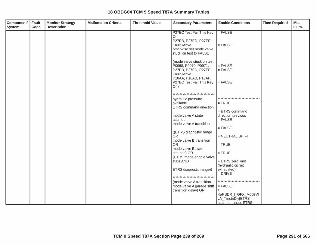
Component/System
FaultCode
Monitor StrategyDescription
Malfunction Criteria Threshold Value Secondary Parameters Enable Conditions Time Required MILIllum.
P27EC Test Fail This KeyOnP27EB, P27ED, P27EEFault Activeotherwise set mode valvestuck on test to FALSE
(mode valve stuck on testP0968, P0970, P0971,P27EB, P27ED, P27EE,Fault ActiveP18AA, P18AB, P18AF,P27EC Test Fail This KeyOn)
******************************hydraulic pressureavailableETRS command direction
mode valve A stateattainedmode valve A transition
((ETRS diagnostic rangeORmode valve B transitionORmode valve B stateattained) OR(ETRS mode enable valvestate AND
ETRS diagnostic range))
******************************(mode valve A transitionmode valve A garage shifttransition delay) OR
= FALSE
= FALSE
= FALSE= FALSE
= FALSE
******************************= TRUE
= ETRS commanddirection previous= FALSE
= FALSE
= NEUTRAL SHIFT
= TRUE
= TRUE
= ETRS zero limit(hydraulic cicruitexhausted)= DRIVE
******************************= FALSE
KaPSDR_t_GFX_ModeVlvA_TrnstnDly[ETRSattained range, ETRS
18 OBDG04 TCM 9 Speed T87A Summary Tables
TCM 9 Speed T87A Section Page 239 of 269 Page 291 of 566
Component/System
FaultCode
Monitor StrategyDescription
Malfunction Criteria Threshold Value Secondary Parameters Enable Conditions Time Required MILIllum.
mode valve A garage shifttransition delay
command range]see supporting tables> 0.0 seconds
18 OBDG04 TCM 9 Speed T87A Summary Tables
TCM 9 Speed T87A Section Page 240 of 269 Page 292 of 566

Component/System
FaultCode
Monitor StrategyDescription
Malfunction Criteria Threshold Value Secondary Parameters Enable Conditions Time Required MILIllum.
Transmission RangeControl APositionSensor/SwitchCircuit Low
P27ED The diagnostic monitordetects a ground shortor open circuit fault onthe mode valve Aposition sensor circuit.
raw sensor voltage < volts0.414 diagnostic monitor enablebattery voltagebattery voltage timeETRS systemconfiguration is internalERTSpark sensor configurationtype is hall sensor
= Boolean1volts9.00seconds1.00
=CeTRGR_e_InternalETRS
= CePSCR_e_HallSns
seconds0.100in second0.163sample
6.25 millisecondupdate rate
Type A,1 Trips
18 OBDG04 TCM 9 Speed T87A Summary Tables
TCM 9 Speed T87A Section Page 241 of 269 Page 293 of 566

Component/System
FaultCode
Monitor StrategyDescription
Malfunction Criteria Threshold Value Secondary Parameters Enable Conditions Time Required MILIllum.
Transmission RangeControl APositionSensor/SwitchCircuit High
P27EE The diagnostic monitordetects a short tovoltage on the modevalve A position sensorcircuit.
raw sensor voltage > volts2.538 diagnostic monitor enablebattery voltagebattery voltage timeETRS systemconfiguration is internalERTSpark sensor configurationtype is hall sensor
= Boolean1volts9.00seconds1.00
=CeTRGR_e_InternalETRS
= CePSCR_e_HallSns
seconds0.100in second0.163sample
6.25 millisecondupdate rate
Type A,1 Trips
18 OBDG04 TCM 9 Speed T87A Summary Tables
TCM 9 Speed T87A Section Page 242 of 269 Page 294 of 566

Component/System
FaultCode
Monitor StrategyDescription
Malfunction Criteria Threshold Value Secondary Parameters Enable Conditions Time Required MILIllum.
Transmission RangeControl BPositionSensor/SwitchCircuit/Open
P27EF The diagnostic monitordetects an illegalvoltage on the modevalve B position sensorcircuit.
raw sensor voltageraw sensor voltage
> volts1.263< volts1.504
diagnostic monitor enablebattery voltagebattery voltage timeETRS systemconfiguration is internalERTSpark sensor configurationtype is hall sensor
= Boolean1volts9.00seconds1.00
=CeTRGR_e_InternalETRS
= CePSCR_e_HallSns
seconds0.100in second0.163sample
6.25 millisecondupdate rate
18 OBDG04 TCM 9 Speed T87A Summary Tables
TCM 9 Speed T87A Section Page 243 of 269 Page 295 of 566

Component/System
FaultCode
Monitor StrategyDescription
Malfunction Criteria Threshold Value Secondary Parameters Enable Conditions Time Required MILIllum.
Transmission RangeControl BPositionSensor/SwitchCircuit Low
P27F1 The diagnostic monitordetects a ground shortor open circuit fault onthe mode valve Bposition sensor circuit.
raw sensor voltage > volts0.414 diagnostic monitor enablebattery voltagebattery voltage timeETRS systemconfiguration is internalERTSpark sensor configurationtype is hall sensor
= Boolean1volts9.00seconds1.00
=CeTRGR_e_InternalETRS
= CePSCR_e_HallSns
seconds0.100in second0.163sample
6.25 millisecondupdate rate
Type A,1 Trips
18 OBDG04 TCM 9 Speed T87A Summary Tables
TCM 9 Speed T87A Section Page 244 of 269 Page 296 of 566

Component/System
FaultCode
Monitor StrategyDescription
Malfunction Criteria Threshold Value Secondary Parameters Enable Conditions Time Required MILIllum.
Transmission RangeControl BPositionSensor/SwitchCircuit High
P27F2 The diagnostic monitordetects a short tovoltage on the modevalve B position sensorcircuit.
raw sensor voltage > volts2.538 diagnostic monitor enablebattery voltagebattery voltage timeETRS systemconfiguration is internalERTSpark sensor configurationtype is hall sensor
= Boolean1volts9.00seconds1.00
=CeTRGR_e_InternalETRS
= CePSCR_e_HallSns
seconds0.100in second0.163sample
6.25 millisecondupdate rate
18 OBDG04 TCM 9 Speed T87A Summary Tables
TCM 9 Speed T87A Section Page 245 of 269 Page 297 of 566
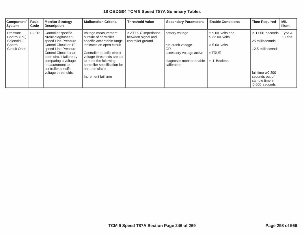
Component/System
FaultCode
Monitor StrategyDescription
Malfunction Criteria Threshold Value Secondary Parameters Enable Conditions Time Required MILIllum.
PressureControl (PC)Solenoid GControlCircuit Open
P2812 Controller specificcircuit diagnoses 9speed Line PressureControl Circuit or 10speed Line PressureControl Circuit for anopen circuit failure bycomparing a voltagemeasurement tocontroller specificvoltage thresholds.
Voltage measurementoutside of controllerspecific acceptable rangeindicates an open circuit
Controller specific circuitvoltage thresholds are setto meet the followingcontroller specification foran open circuit
Increment fail time
200 K impedancebetween signal andcontroller ground
battery voltage
run crank voltageORaccessory voltage active
diagnostic monitor enablecalibration
volts and9.00volts32.00
volts5.00
= TRUE
= Boolean1
seconds1.000
25 milliseconds
12.5 milliseconds
fail time 0.300seconds out ofsample time
seconds0.500
Type A,1 Trips
18 OBDG04 TCM 9 Speed T87A Summary Tables
TCM 9 Speed T87A Section Page 246 of 269 Page 298 of 566
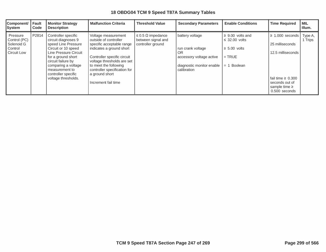
Component/System
FaultCode
Monitor StrategyDescription
Malfunction Criteria Threshold Value Secondary Parameters Enable Conditions Time Required MILIllum.
PressureControl (PC)Solenoid GControlCircuit Low
P2814 Controller specificcircuit diagnoses 9speed Line PressureCircuit or 10 speedLine Pressure Circuitfor a ground shortcircuit failure bycomparing a voltagemeasurement tocontroller specificvoltage thresholds.
Voltage measurementoutside of controllerspecific acceptable rangeindicates a ground short
Controller specific circuitvoltage thresholds are setto meet the followingcontroller specification fora ground short
Increment fail time
0.5 impedancebetween signal andcontroller ground
battery voltage
run crank voltageORaccessory voltage active
diagnostic monitor enablecalibration
volts and9.00volts32.00
volts5.00
= TRUE
= Boolean1
seconds1.000
25 milliseconds
12.5 milliseconds
fail time 0.300seconds out ofsample time
seconds0.500
Type A,1 Trips
18 OBDG04 TCM 9 Speed T87A Summary Tables
TCM 9 Speed T87A Section Page 247 of 269 Page 299 of 566

Component/System
FaultCode
Monitor StrategyDescription
Malfunction Criteria Threshold Value Secondary Parameters Enable Conditions Time Required MILIllum.
PressureControl (PC)Solenoid GControlCircuit High
P2815 Controller specificcircuit diagnoses 9speed Line PressureCircuit or 10 speedLine Pressure Circuitfor a short to voltagecircuit failure bycomparing a voltagemeasurement tocontroller specificvoltage thresholds.
Voltage measurementoutside of controllerspecific acceptable rangeindicates a short tovoltage
Controller specific circuitvoltage thresholds are setto meet the followingcontroller specification fora short to voltage
Increment fail time
0.5 impedancebetween signal andcontroller voltagesource
battery voltage
run crank voltageORaccessory voltage active
diagnostic monitor enablecalibration
volts and9.00volts32.00
volts5.00
= TRUE
= Boolean1
seconds1.000
25 milliseconds
12.5 milliseconds
fail time 0.300seconds out ofsample time
seconds0.500
Type A,1 Trips
18 OBDG04 TCM 9 Speed T87A Summary Tables
TCM 9 Speed T87A Section Page 248 of 269 Page 300 of 566

Component/System
FaultCode
Monitor StrategyDescription
Malfunction Criteria Threshold Value Secondary Parameters Enable Conditions Time Required MILIllum.
PressureControlSolenoid HPerformance/Stuck Off
P2817 The diagnostic monitordetects thetransmission torqueconverter control valvesolenoid failedhydraulically off. Themonitor executes whenthe transmission torqueconverter iscommanded to a “lock”mode during which thetorque converter will becontrolled to near zero(0.0) RPM slip speed,or, an “on” mode duringwhich the torqueconverter will becontrolled to target slipspeed using slip speederror. The transmissiontorque convertercontrol valve solenoidis considered failedhydraulically off whenthe “lock” mode slipspeed is excessive, or,when the ‘on” modeslip speed error isexcessive.
if use TCC slip speederror ORTCC control mode
TCC slip speed error =TCC slip speed - TCCcomand slip speed
else ifTCC control modetorque convert slip =engine speed -transmission input shaftspeed
thenupdate fail time25 millisecond update rate
= Boolean0
= ON mode (controlledslip mode)
P2817 TCC stuck offfail TCC slip speedsee supporting table
= LOCKRPM130.0
diagnostic monitor enable
TCC command capacity
TCC command pressure
(TCC control modepreviousTCC control modepreviousTCC control modeprevious)AND(TCC control modecurrent ORTCC control modecurrent)
(TCC stuck off enableORTCC stuck on enable)hydraulic pressureavailable:engine speed
= Boolean1
%0.00
kPa800.0
TCC control modecurrent ON mode (controlled
slip mode) LOCK
= ON mode (controlledslip mode)= LOCK
= Boolean1
= Boolean1
RPM400.0
fail time 2.500secondsincrement failcountfail count 3counts25 millisecondupdate rate
TCC commandcapacity time
seconds0.00
TCC commandpressure time
seconds2.00
engine speedtime engine speedtime fortransmissionhydraulicpressureavailable
Type B,2 Trips
18 OBDG04 TCM 9 Speed T87A Summary Tables
TCM 9 Speed T87A Section Page 249 of 269 Page 301 of 566

Component/System
FaultCode
Monitor StrategyDescription
Malfunction Criteria Threshold Value Secondary Parameters Enable Conditions Time Required MILIllum.
service fast learn activebattery voltage
run crank voltage
P281B falut activeP281D falut activeP281E falut activeP0722 fault pendingP0723 fault pendingP0716 fault pendingP0717 fault pendingP07BF fault pendingP07C0 fault pending(PTO active ORPTO disable calibration)accelerator pedal positionaccelerator pedal positionrange shift statetransmission fluidtemperaturetransmission fluidtemperatureengine torqueengine torqueP2817 test fail this key on(TCC control mode OR
TCC control mode)break latch state (clutchselect valve solenoid)attained gear
attained gear slip
DTCs not fault active
= FALSEvolts9.00
volts9.00
= FALSE= FALSE= FALSE= FALSE= FALSE= FALSE= FALSE= FALSE= FALSE= FALSE= Boolean1
%8.0%100.0
= range shift complete°C-6.66
°C130.0
Nm50.0Nm8,191.8
= FALSE= ON mode (controlledslip mode)= LOCK= disabled (clutch selectvalve not transitioning) CeCGSR_e_CR_Third
RPM25
AcceleratorPedalFailureEngineTorqueEstInaccurate
see supportinftable
battery voltagetime 0.100secondsrun crank voltagetime 0.100seconds
18 OBDG04 TCM 9 Speed T87A Summary Tables
TCM 9 Speed T87A Section Page 250 of 269 Page 302 of 566

Component/System
FaultCode
Monitor StrategyDescription
Malfunction Criteria Threshold Value Secondary Parameters Enable Conditions Time Required MILIllum.
P0716, P0717, P07BF,P07C0P0722, P0723, P077C,P077D
18 OBDG04 TCM 9 Speed T87A Summary Tables
TCM 9 Speed T87A Section Page 251 of 269 Page 303 of 566

Component/System
FaultCode
Monitor StrategyDescription
Malfunction Criteria Threshold Value Secondary Parameters Enable Conditions Time Required MILIllum.
PressureControlSolenoid HStuck On -GF9 specific
P2818 The diagnostic monitordetects thetransmission torqueconverter control valvesolenoid failedhydraulically on. Thetorque converterhydraulic control circuitis multiplexed with thetransmission clutchselect valve hydrauliccontrol circuit, allowingfor the torque convertercontrol valve solenoidstuck on test to executewhen the clutch selectvalve solenoid iscommanded ON.When the clutch selectvalve solenoid iscommanded ON as thevehicle speeddecreases toward zeroKPH, and, if the torqueconverter control valvesolenoid is stuck on,the torque converterslip speed rate ofchange will have alarge slope whiledecreasing toward zeroRPM, and the torqueconverter slip speedwill remain low nearzero RPM.
while control valve testtime timing down:rate of change of torqueconvert slip speed = (ABS(current loop value torqueconvert slip speed -previous loop valuetorque convert slipspeed) / 25 milliseconds)when clutch select valvesoleniod multiplexed toTCC hydraulicANDtorque convert slip speed= ABS(engine speed -transmission input shaftspeed)ANDtorque convert slip speed= engine speed -transmission input shaftspeedtorque convert slip speedtorque convert slip speedTHENincrement fail time25 millisecond update rate
P2818 torque convertderivative slip speedfail thresholdsee supporting table
P0741 (GF9 specific)TCC slip speed crashRPM
RPM-50.0RPM30.0
diagnostic monitor enable(TCC stuck off enableORTCC stuck on enable)hydraulic pressureavailable:engine speed
service fast learn activebattery voltage
run crank voltage
P281B falut activeP281D falut activeP281E falut active
PRNDLPRNDLtransmission fluidtemperaturetransmission fluid
= Boolean1= Boolean1
= Boolean1
RPM400.0
= FALSEvolts9.00
volts9.00
= FALSE= FALSE= FALSE
NEUTRAL REVERSE
°C-6.66
°C130.00
fail time 1.500secondsincrement failcountfail count 4counts25 millisecondupdate rate
engine speedtime engine speedtime fortransmissionhydraulicpressureavailablesee supportinftable
battery voltagetime 0.100secondsrun crank voltagetime 0.100seconds
Type A,1 Trips
18 OBDG04 TCM 9 Speed T87A Summary Tables
TCM 9 Speed T87A Section Page 252 of 269 Page 304 of 566

Component/System
FaultCode
Monitor StrategyDescription
Malfunction Criteria Threshold Value Secondary Parameters Enable Conditions Time Required MILIllum.
temperatureaccelerator pedal positionaccelerator pedal positionvehicle speedvehicle speedTCC command modebreak latch state (clutchselect valve solenoid)P0722 fault pendingP0723 fault pendingP0716 fault pendingP0717 fault pendingP07BF fault pendingP07C0 fault pending(PTO active ORPTO disable calibration)transmission fluidtemperaturetransmission fluidtemperatureengine torqueengine torqueP2818 test fail this key onvehicle speedengine speedengine speedaccelerator pedal position4WD low state(driver shift mode activeORdriver shift modecalibration)(misfire requests TCC offORmisfire TCC offcalibration)(clucth control solenoidstuck on OR stuck OFFintrusive shift active)P0746 fault pendingP0747 fault pendingP0776 fault pending
%0.00%1.00
KPH3.0KPH9.5
= OFF disabled (clutch select
valve transitioning)= FALSE= FALSE= FALSE= FALSE= FALSE= FALSE= FALSE= Boolean1
°C-6.66
°C130.00
Nm55.0Nm800.0
= FALSEKPH45.0RPM400.0
RPM5,500.0%95.0
= FALSE= FALSE
= Boolean0
= FALSE
= Boolean0
= FALSE
= FALSE= FALSE= FALSE
18 OBDG04 TCM 9 Speed T87A Summary Tables
TCM 9 Speed T87A Section Page 253 of 269 Page 305 of 566

Component/System
FaultCode
Monitor StrategyDescription
Malfunction Criteria Threshold Value Secondary Parameters Enable Conditions Time Required MILIllum.
P0777 fault pendingP0796 fault pendingP0797 fault pendingP2714 fault pendingP2715 fault pendingP2723 fault pendingP2724 fault pendingP2732 fault pendingP2733 fault pendingP2820 fault pendingP2821 fault pendingvehicle speedaccelerator pedal positionhysteresis
when:break latch state (clutchselect valve solenoid)previous break latch state(clutch select valvesolenoid)set stuck on test time andbegin time down,stuck on test time musttime down from calibrationvalue to zero (0.0)seconds
break latch state (clutchselect valve solenoid)AND
previous break latch state(clutch select valvesolenoid)THEN initializecontrol valve test time,control valve test timemust time down fromcalibration value to zero(0.0) seconds
= FALSE= FALSE= FALSE= FALSE= FALSE= FALSE= FALSE= FALSE= FALSE= FALSE= FALSE
KPH8.0%4.0
> %1.0
= disabled (clutch selectvalve not transitioning)= complete (clutch selectvalve transition complete)
=P2818 stuck on test timesee supporting tables
= clutch select valvesolenoid mutliplexed toTCC hydraulic
= disabled (clutch selectvalve not transitioning)
=P2818 (GF9 specific)control valve test timesee supporting tables
18 OBDG04 TCM 9 Speed T87A Summary Tables
TCM 9 Speed T87A Section Page 254 of 269 Page 306 of 566

Component/System
FaultCode
Monitor StrategyDescription
Malfunction Criteria Threshold Value Secondary Parameters Enable Conditions Time Required MILIllum.
DTCs not fault active AcceleratorPedalFailureEngineTorqueEstInaccurateP0716, P0717, P07BF,P07C0P0722, P0723, P077C,P077D
18 OBDG04 TCM 9 Speed T87A Summary Tables
TCM 9 Speed T87A Section Page 255 of 269 Page 307 of 566

Component/System
FaultCode
Monitor StrategyDescription
Malfunction Criteria Threshold Value Secondary Parameters Enable Conditions Time Required MILIllum.
PressureControlSolenoid HControlCircuit/Open
P281B Controller specificcircuit diagnoses 9speed TCC ControlCircuit or 10 speedTCC Control Circuit foran open circuit failureby comparing a voltagemeasurement tocontroller specificvoltage thresholds.
Voltage measurementoutside of controllerspecific acceptable rangeindicates an open circuit
Controller specific circuitvoltage thresholds are setto meet the followingcontroller specification foran open circuit
Increment fail time
200 K impedancebetween signal andcontroller ground
battery voltage
run crank voltageORaccessory voltage active
diagnostic monitor enablecalibration
volts and9.00volts32.00
volts5.00
= TRUE
= Boolean1
seconds1.000
25 milliseconds
12.5 milliseconds
fail time 0.300seconds out ofsample time
seconds0.500
Type B,2 Trips
18 OBDG04 TCM 9 Speed T87A Summary Tables
TCM 9 Speed T87A Section Page 256 of 269 Page 308 of 566

Component/System
FaultCode
Monitor StrategyDescription
Malfunction Criteria Threshold Value Secondary Parameters Enable Conditions Time Required MILIllum.
PressureControlSolenoid HControlCircuit Low
P281D Controller specificcircuit diagnoses 9speed TCC PressureControl Circuit or 10speed TCC ControlCircuit for a groundshort circuit failure bycomparing a voltagemeasurement tocontroller specificvoltage thresholds.
Voltage measurementoutside of controllerspecific acceptable rangeindicates a ground short
Controller specific circuitvoltage thresholds are setto meet the followingcontroller specification fora ground short
Increment fail time
0.5 impedancebetween signal andcontroller ground
battery voltage
run crank voltageORaccessory voltage active
diagnostic monitor enablecalibration
volts and9.00volts32.00
volts5.00
= TRUE
= Boolean1
seconds1.000
25 milliseconds
12.5 milliseconds
fail time 0.300seconds out ofsample time
seconds0.500
Type A,1 Trips
18 OBDG04 TCM 9 Speed T87A Summary Tables
TCM 9 Speed T87A Section Page 257 of 269 Page 309 of 566

Component/System
FaultCode
Monitor StrategyDescription
Malfunction Criteria Threshold Value Secondary Parameters Enable Conditions Time Required MILIllum.
PressureControlSolenoid HControlCircuit High
P281E Controller specificcircuit diagnoses 9speed TCC PressureControl Circuit or 10speed TCC ControlCircuit for a short tovoltage circuit failure bycomparing a voltagemeasurement tocontroller specificvoltage thresholds.
Voltage measurementoutside of controllerspecific acceptable rangeindicates a short tovoltage
Controller specific circuitvoltage thresholds are setto meet the followingcontroller specification fora short to voltage
Increment fail time
0.5 impedancebetween signal andcontroller voltagesource
battery voltage
run crank voltageORaccessory voltage active
diagnostic monitor enablecalibration
volts and9.00volts32.00
volts5.00
= TRUE
= Boolean1
seconds1.000
25 milliseconds
12.5 milliseconds
fail time 0.300seconds out ofsample time
seconds0.500
Type B,2 Trips
18 OBDG04 TCM 9 Speed T87A Summary Tables
TCM 9 Speed T87A Section Page 258 of 269 Page 310 of 566

Component/System
FaultCode
Monitor StrategyDescription
Malfunction Criteria Threshold Value Secondary Parameters Enable Conditions Time Required MILIllum.
PressureControl (PC)Solenoid JStuck Off
P2820 Each pressure controlsolenoid stuck offdiagnostic monitordetects a clutchpressure controlsolenoid failedhydraulically off, whilethe solenoid iselectrically functional.This diagnostic monitordetects the clutchselect valve solenoidfailed hydraulically off.The clutch select valveis used to routehydraulic fluid to, either,the selectable one wayclutch hydraulic circuitused to attaintransmission 1st gearlock state, or, to the C6- C6789 clutchhydraulic circuitnecessary fortransmission highergear states.
When the clutch selectvalve is failedhydraulically off, andtransmission is in 1stgear lock state, it ispossible to measurelow C6 - C6789 clutchslip speed as hydraulicfluid is routed to theclutch C6 - C6789, or,6th gear transmissiongear ratio, based ontransmission levernode design, the
gear ratiogear ratioORC6 clutch slip speed,update fail time6.25 milliscond update
1.700 1.200
RPM20.0
use battery voltagecalibration is FALSEOR(use battery voltagecalibration is TRUEANDbattery voltage
use run crank voltagecalibration is FALSEOR(use run crank voltagecalibration is TRUEANDrun crank voltage
TCM output driver highside driver 1, clutchpressure control solenoiddriver circuit enabled
TCM output driver highside driver 2, clutchpressure control solenoiddriver circuit enabled
service fast learn activeservice solenoid cleaningprocedure active
hydraulic pressure
= Boolean1
= Boolean1
volts9.00
= Boolean0
= Boolean0
volts9.00
= TRUE Boolean
= TRUE Boolean
= FALSE Boolean= FALSE Boolean
fail time 0.250seconds,update fail count,fail count 3counts6.25 milliscondupdate
battery voltagetime 0.100seconds
run crank voltagetime 0.100seconds
Type A,1 Trips
18 OBDG04 TCM 9 Speed T87A Summary Tables
TCM 9 Speed T87A Section Page 259 of 269 Page 311 of 566

Component/System
FaultCode
Monitor StrategyDescription
Malfunction Criteria Threshold Value Secondary Parameters Enable Conditions Time Required MILIllum.
transmission input shaftspeed, thetransmission outputshaft speed, and onetransmissionintermediate shaftspeed, while notcommanding 6th-9thgear, as the indicationof the failure mode.
This diagnostic monitoris relative to the GF9clutch select valvepressure controlsolenoid.
available:engine speed
diagnostic monitorenabledtransmission output shaftspeedtransmission fluidtemperaturetransmission fluidtemperatureP2820 test fail this key on(command gear ORattained gear)
DTCs not fault pending
DTCs not test fail this keyon
DTCs not fault active
RPM400.0
= Booelan1
RPM35
°C-256.00
°C130.0
= FALSE= 1st lock= 1st lock
P0716 P0717 P0722P0723 P077C P077DP07BF P07C0
P0707 P0708 P0746P0747 P0776 P0777P0796 P0797 P2714P2715 P2723 P2724P2732 P2733 P2820P2821
AcceleratorPedalFailureCrankSensor_FAP0707 P0708 P0716P0717 P07BF P07C0P0722 P0723 P077CP077D P172A P172BP176B P176C P176DP17C5 P17CC P17CD
engine speedtime engine speedtime fortransmissionhydraulicpressureavailablesee supportingtable
18 OBDG04 TCM 9 Speed T87A Summary Tables
TCM 9 Speed T87A Section Page 260 of 269 Page 312 of 566

Component/System
FaultCode
Monitor StrategyDescription
Malfunction Criteria Threshold Value Secondary Parameters Enable Conditions Time Required MILIllum.
P17CE P17D3 P17D6P2805
18 OBDG04 TCM 9 Speed T87A Summary Tables
TCM 9 Speed T87A Section Page 261 of 269 Page 313 of 566

Component/System
FaultCode
Monitor StrategyDescription
Malfunction Criteria Threshold Value Secondary Parameters Enable Conditions Time Required MILIllum.
PressureControlSolenoid JStuck On
P2821 Each pressure controlsolenoid stuck ondiagnostic monitordetects a clutchpressure controlsolenoid failedhydraulically on, whilethe solenoid iselectrically functional.The clutch selectpressure controlsolenoid must behydraulically off and theclutch select valve inthe off state, to allowhydraulic fluid supply tothe C3 (CB38) or C4(C4) or C5 (C57R)clutches, such thatwhen activated,commanded gear 3rdor 4th or 5th can beattained. With theclutch select valvepressure controlsolenoid failedhydraulically on,commanded gear 3rdor 4th or 5th cannot beattained. In the failuremode, the clutch slipspeed, and gear boxgear slip, will beexcessive, not near orat zero RPM, whencommanding 3rd or 4thor 5th gear, but due tothe clutch selectpressure controlsolenoid failedhydraulically on and not
Cx clutch slip speed failcompareC3 (CB38) ORC4 (C4) ORC5 (C57R)update Cx clutch slipspeed fail time6.25 milliscond update
once intrusive gear iscommanded andclutch select stuck on testactive remains andCx clutch fail count limitoccurs,increment clutch selectvalve solenoid stuck onfail count andtime up clutch select stuckon test gear time6.25 milliscond update
RPM200.0RPM200.0RPM200.0
= TRUE
Cx clutch slipspeed fail time C3 (CB38) 3.00secondsORC4 (C4) 3.00secondsORC5 (C57R) 3.00secondsupdate Cx failcount,Cx fail count C3 (CB38) 3countsORC4 (C4) 3countsORC5 (C57R) 3counts,Cx clutch failcount limitoccurs6.25 milliscondupdate
clutch selectvalve solenoidstuck on failcount 2countsORclutch selectstuck on testgear time 9.00seconds6.25 milliscondupdate
Type A,1 Trips
18 OBDG04 TCM 9 Speed T87A Summary Tables
TCM 9 Speed T87A Section Page 262 of 269 Page 314 of 566

Component/System
FaultCode
Monitor StrategyDescription
Malfunction Criteria Threshold Value Secondary Parameters Enable Conditions Time Required MILIllum.
individual clutch controlfaults. It is thusnecessary, whenindividual clutch slipoccurs in 3rd or 4th or5th gear and countedtoward the clutchpressure controlsolenoid stuck onfailure, for an intrusivegear commanded from3rd or 4th or 5th toverify the clutch slip inthe remaining gearstates. The individualclutch slip that occursin those intrusivegears, 3rd or 4th or 5th,is also counted towardthe clutch pressurecontrol solenoid stuckon failure. As individualclutch slip isaccumulated in eachcommanded gear 3rdor 4th or 5th, thatfailure time is theverification of the clutchpressure controlsolenoid failedhydraulically on.
The clutch slip speed iscalculated based onthe transmission levernode design, requiringtransmission input shaftspeed, transmissionoutput shaft speed,and, one transmissionintermediate shaftspeed. The clutch
use battery voltagecalibration is FALSEOR(use battery voltagecalibration is TRUEANDbattery voltage
use run crank voltagecalibration is FALSEOR(use run crank voltagecalibration is TRUEANDrun crank voltage
TCM output driver highside driver 1, clutchpressure control solenoiddriver circuit enabled
TCM output driver highside driver 2, clutchpressure control solenoiddriver circuit enabled
service fast learn activeservice solenoid cleaningprocedure active
hydraulic pressureavailable:engine speed
= Boolean1
= Boolean1
volts9.00
= Boolean0
= Boolean0
volts9.00
= TRUE Boolean
= TRUE Boolean
= FALSE Boolean= FALSE Boolean
RPM400.0
battery voltagetime 0.100seconds
run crank voltagetime 0.100seconds
engine speedtime engine speedtime fortransmissionhydraulicpressureavailablesee supporting
18 OBDG04 TCM 9 Speed T87A Summary Tables
TCM 9 Speed T87A Section Page 263 of 269 Page 315 of 566

Component/System
FaultCode
Monitor StrategyDescription
Malfunction Criteria Threshold Value Secondary Parameters Enable Conditions Time Required MILIllum.
pressure controlsolenoid is tested afteran automatictransmission shiftoccurs and has beenconsidered shiftcomplete, or, steadystate gear is deemedactive, range shiftcomplete. When theautomatic transmissionshift is complete,steady state gear isconsidered, the clutchpressure controlsolenoid is mapped totransmission linepressure control, whichnormally allows theclutch to maintain fulltorque holding capacityat the given enginecrankshaft torque, tomaintain true gearratio. When the clutchselect pressure controlsolenoid is failedhydraulically on, C3(CB38) or C4 (C4) orC5 (C57R) clutchescannot maintainholding capacity at anyengine crankshafttorque, and the clutchslip speed isuncontrollable.
The clutch pressurecontrol solenoid test issuspended if the higherlevel safety startlemitigation function is
diagnostic monitor enable
P2821 test fail this key on
test trigger set to TRUE:enable forward gear ANDdirection requestORenable reverse gear ANDdirection requestcurrent loop test triggerclutch control solenoidtest staterange shift state
clutch solenoid test stateset to NEUTRAL TESTwhen:test triggerinitialize range shiftcomplete time,whenrange shift state,range shift complete timemust time down to zerowhenrange shift complete
Cx indicates any one ofthe 4 clutches:C3 (CB38) ORC4 (C4) ORC5 (C57R)
enable Cx clutch slipspeed fail compare when:diagnostic clutch test Cx((startle mitigation active
= Boolean1
= FALSE
= Boolean1= forward gear
= Boolean0= reverse gear= FALSE NEUTRAL TEST
= range shift completed
= TRUE
range shift completed
= HOLDING CLUTCH= FALSE
table
initialize rangeshift completetime = 1.000seconds,range shiftcomplete timemust time downto zerowhenrange shiftcomplete
18 OBDG04 TCM 9 Speed T87A Summary Tables
TCM 9 Speed T87A Section Page 264 of 269 Page 316 of 566

Component/System
FaultCode
Monitor StrategyDescription
Malfunction Criteria Threshold Value Secondary Parameters Enable Conditions Time Required MILIllum.
active. The safetystartle mitigationfunction is triggeredwhen a sudden vehicledeceleration occursdue to a clutchpressure controlsolenoid that has failedhydraulically on, whilethe solenoid iselectrically functional,which, must takepriority over this clutchselect pressure controlsolenoid stuck offdiagnostic monitor. Allclutch pressure controlsolenoid stuck on/offdiagnostic monitors areemission MIL DTCs.System voltage mustbe normal, all clutchpressure controlsolenoid driver circuitsmust be functional, noclutch pressure controlsolenoid electrical orperformance faults canbe present, and nospeed sensor electricalor performance faultscan be present, or thea clutch pressurecontrol solenoid stuckoff test is disabled.
This diagnostic monitoris relative to the GF9clutch select valvepressure controlsolenoid.
OR(startle mitigation activeANDstartle mitigation gear))(see startle mitigationactive NOTE below)unintended decelerationfault pending ORunintended decelerationfault pending enableFASLE(startle mitigation)clutch steady stateadaptive activetransmission output shaftspeedCx clutch slip speed valid,all speed sesnors arefunctional for lever nodeclucth slip speedcalculation
accelerator pedal positionengine speed
diagnostic clutch test Cxset to HOLDING CLUTCHwhen:clutch solenoid test state((startle mitigation activeOR(startle mitigation activeANDstartle mitigation gear))(see startle mitigationactive NOTE below)Cx clutch pressured map
clutch select stuck on test
= TRUE
initial startle mitigationgear
= FALSE
= Boolean0
= FALSE
RPM89.0
%2.00RPM1,500.0
= NEUTRAL TEST= FALSE
= TRUE
initial startle mitigationgear
= mapped to linepressure, Cx clutchpressure has transtionedfrom off-applying-applied
18 OBDG04 TCM 9 Speed T87A Summary Tables
TCM 9 Speed T87A Section Page 265 of 269 Page 317 of 566

Component/System
FaultCode
Monitor StrategyDescription
Malfunction Criteria Threshold Value Secondary Parameters Enable Conditions Time Required MILIllum.
active set to TRUE when:command gearclutch control solenoidtest stateany Cx clutch fail countlimit occursbreak latch state, clutchselect valve hydrauliclatch fluid is applied,hydraulic latch fluid forcebalance acts with clutchselect valve return spring,to force the clutch selectvalve to the off postion innormal operation, allowinghydraulic fluid to C3(CB38) C4 (C4) and C5(C57R) clutches
clutch select stuck on testactivedriver direction (PRNDL)change request,select intrusive gear toverify clutch select valvesolenoid when HOLDINGCLUTCH:C3 (CB38)C4 (C4)C5 (C57R)enable clutch select stuckon test gear time
NOTE: startle mitigationactive is used to detectunintended decelerationdue to clutch pressurecontrol solenoid stuck onfailure modes, the clutchpressure control solenoidstuck on DTCs being
REVERSE= NEUTRAL TEST
= complete
= TRUE
= FALSE
= CeCGSR_e_Fourth= CeCGSR_e_Fifth= CeCGSR_e_Fourth
18 OBDG04 TCM 9 Speed T87A Summary Tables
TCM 9 Speed T87A Section Page 266 of 269 Page 318 of 566

Component/System
FaultCode
Monitor StrategyDescription
Malfunction Criteria Threshold Value Secondary Parameters Enable Conditions Time Required MILIllum.
P0747 P0777 P0797P2715 P2724 P2733P2821
DTCs not fault pending
DTCs not test fail this keyon
DTCs not fault active
P0716 P0717 P0722P0723 P077C P077DP07BF P07C0
P0707 P0708 P0746P0747 P0776 P0777P0796 P0797 P2714P2715 P2723 P2724P2732 P2733 P2820P2821
AcceleratorPedalFailureCrankSensor_FAP0707 P0708 P0716P0717 P07BF P07C0P0722 P0723 P077CP077D P172A P172BP176B P176C P176DP17C5 P17CC P17CDP17CE P17D3 P17D6P2805
18 OBDG04 TCM 9 Speed T87A Summary Tables
TCM 9 Speed T87A Section Page 267 of 269 Page 319 of 566

Component/System
FaultCode
Monitor StrategyDescription
Malfunction Criteria Threshold Value Secondary Parameters Enable Conditions Time Required MILIllum.
PressureControlSolenoid JControlCircuit Low
P2826 Controller specificcircuit diagnoses 9speed Clutch SelectValve Control Circuit or10 speed PISA ValveControl Circuit for aground short circuitfailure by comparing avoltage measurementto controller specificvoltage thresholds.
Voltage measurementoutside of controllerspecific acceptable rangeindicates a ground short
Controller specific circuitvoltage thresholds are setto meet the followingcontroller specification fora ground short
Increment fail time
0.5 impedancebetween signal andcontroller ground
battery voltage
run crank voltageORaccessory voltage active
diagnostic monitor enablecalibration
volts and9.00volts32.00
volts5.00
= TRUE
= Boolean1
seconds1.000
25 milliseconds
12.5 milliseconds
fail time 0.300seconds out ofsample time
seconds0.500
Type A,1 Trips
18 OBDG04 TCM 9 Speed T87A Summary Tables
TCM 9 Speed T87A Section Page 268 of 269 Page 320 of 566
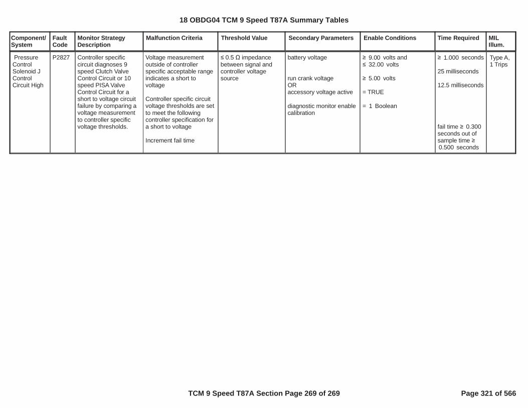
Component/System
FaultCode
Monitor StrategyDescription
Malfunction Criteria Threshold Value Secondary Parameters Enable Conditions Time Required MILIllum.
PressureControlSolenoid JControlCircuit High
P2827 Controller specificcircuit diagnoses 9speed Clutch ValveControl Circuit or 10speed PISA ValveControl Circuit for ashort to voltage circuitfailure by comparing avoltage measurementto controller specificvoltage thresholds.
Voltage measurementoutside of controllerspecific acceptable rangeindicates a short tovoltage
Controller specific circuitvoltage thresholds are setto meet the followingcontroller specification fora short to voltage
Increment fail time
0.5 impedancebetween signal andcontroller voltagesource
battery voltage
run crank voltageORaccessory voltage active
diagnostic monitor enablecalibration
volts and9.00volts32.00
volts5.00
= TRUE
= Boolean1
seconds1.000
25 milliseconds
12.5 milliseconds
fail time 0.300seconds out ofsample time
seconds0.500
Type A,1 Trips
18 OBDG04 TCM 9 Speed T87A Summary Tables
TCM 9 Speed T87A Section Page 269 of 269 Page 321 of 566

Component/ Fault Monitor Strategy Secondary MilSystem Code Description Malfunction Illum.
Transmission Control Module (TCM) P0601 Transmission Electro-Hydraulic
Control Module Read Only MemoryIncorrect program/calibrations
checksum = TRUE Boolean >= 5 Fail Counts One Trip
DisableConditions:
MIL not Illuminated forDTC's:
Transmission Control Module (TCM) P0603
Transmission Electro-Hydraulic Control Module Long-Term Memory Reset
Non-volatile memory (static ordynamic) checksum failure at
Powerup= TRUE Boolean Runs
Continously
One Trip
DisableConditions:
MIL not Illuminated forDTC's:
Transmission Control Module (TCM) P0604
Transmission Electro-Hydraulic Control Module Random Access Memory
RAM Read/Write Failure (SingleWord) = TRUE Boolean >= 5 Fail Counts
One Trip
= 16 Sample Counts
DisableConditions:
MIL not Illuminated forDTC's:
Transmission Control Module (TCM) P062F
Transmission Electro-Hydraulic Control Module Long Term Memory Performance
TCM Non-Volatile Memory bitIncorrect flag at Powerdown = TRUE Boolean Runs
Continously
One Trip
DisableConditions:
MIL not Illuminated forDTC's:
Transmission Control Module (TCM) P0634
Transmission Electro-Hydraulic Control Module Internal Temperature Too High
Fail Case 1Substrate Temperature >= 146.296875 ºC >= 5 Fail Time (Sec)
One Trip
Malfunction Threshold Enable TimeCriteria Value Conditions Required
TCM: P0601
ECM: None
TCM: P0603
ECM: None
TCM: P0604
ECM: None
TCM: P062F
ECM: None
18 OBDG04 TCM 6 Speed T43 Summary Tables
TCM 6 Speed T43 Section Page 1 of 78 Page 322 of 566

Component/ Fault Monitor Strategy Secondary MilSystem Code Description Malfunction Illum.
Malfunction Threshold Enable TimeCriteria Value Conditions Required
Fail Case 2
Substrate Temperature >= 50 ºC >= 2 Fail Time (Sec)
Ignition Voltage >= 18 Volts
Note: either fail case can set the DTC
Ignition Voltage Lo >= 8.5996094 VoltsIgnition Voltage Hi <= 31.990234 Volts
Substrate Temp Lo >= 0 ºCSubstrate Temp Hi <= 170 ºC
Substrate Temp Between Temp Range for Time >= 0.25 Sec
P0634 Status is
Test Failed This Key
On or Fault Active
DisableConditions:
MIL not Illuminated forDTC's:
High Side Driver 1 P0658 Actuator Supply Voltage Circuit Low The HWIO reports a low voltage (open or ground short) error flag = TRUE Boolean >= 4 Fail Counts One Trip
outof 6 Sample Counts
P0658 Status is not =
Test FailedThis Key
On or Fault Active
High Side Driver 1 On = True Boolean
TCM: None
ECM: None
18 OBDG04 TCM 6 Speed T43 Summary Tables
TCM 6 Speed T43 Section Page 2 of 78 Page 323 of 566

Component/ Fault Monitor Strategy Secondary MilSystem Code Description Malfunction Illum.
Malfunction Threshold Enable TimeCriteria Value Conditions Required
DisableConditions:
MIL not Illuminated forDTC's:
Transmission Control Module (TCM) P0667 TCM Internal Temp (substrate)
Sensor Circuit Range/PerformanceIf transmission oil temp to
substrate temp >
Refer to Table 19 in
supporting documents
ºC
TwoTrips
If TCM substrate temp to power up temp >
Refer to Table 20 in
supporting documents
ºC
Both conditions above required toincrement fail counter >= 3000 Fail Counts
(100ms loop)Note: table reference temp = to the
median temp of trans oil temp, substrate temp and power up
temp.
Outof 3750 Sample Counts
(100ms loop)
Non-continuous (intermittent) fail conditions will delay resetting fail
counter until>= 700 Pass Counts
(100ms loop)
Out of 875 Sample Counts
(100ms loop)
Engine Torque Signal Valid = TRUE BooleanAccelerator Position Signal
Valid = TRUE Boolean
Ignition Voltage Lo >= 8.5996094 VoltsIgnition Voltage Hi <= 31.990234 VoltsEngine Speed Lo >= 400 RPMEngine Speed Hi <= 7500 RPM
Engine Speed is within the allowable limits for >= 5 Sec
Brake torque active = FALSEBelow describes the brake
torque entry criteriaEngine Torque >= 90 N*m
TCM: None
ECM: None
18 OBDG04 TCM 6 Speed T43 Summary Tables
TCM 6 Speed T43 Section Page 3 of 78 Page 324 of 566
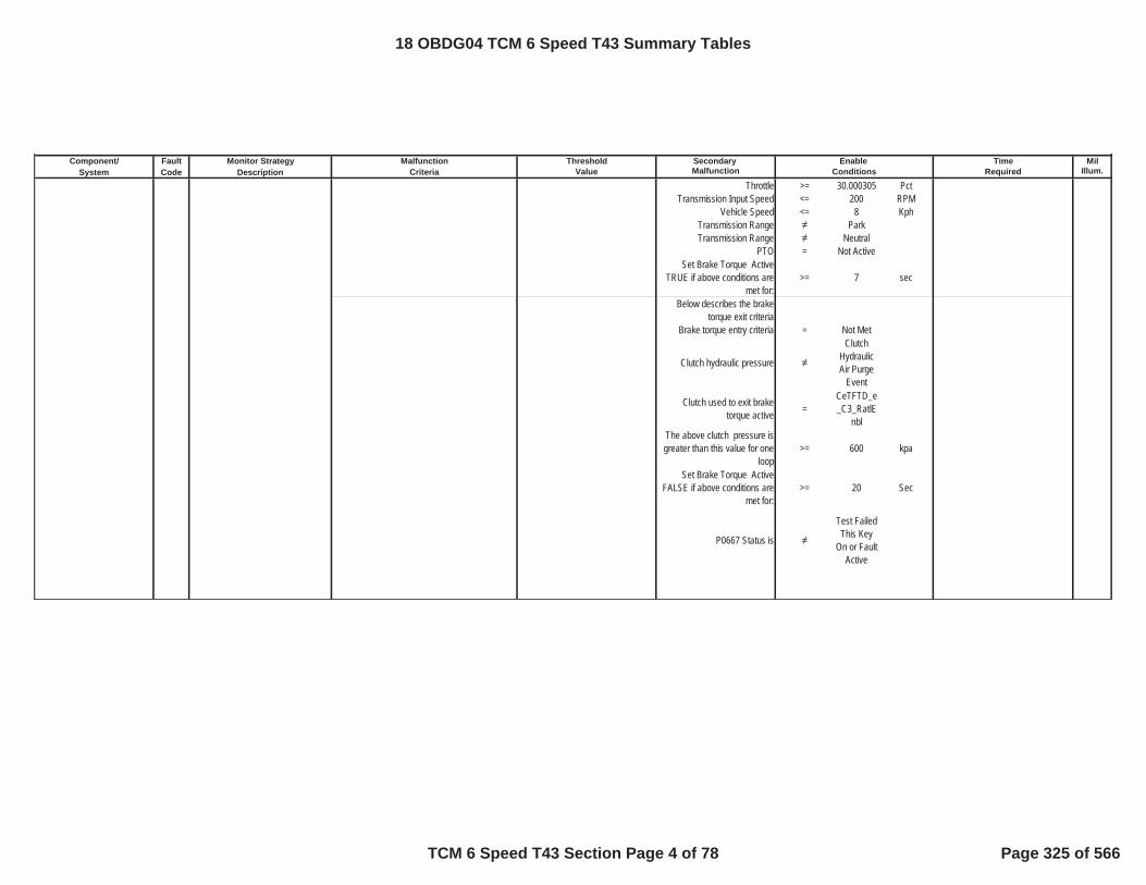
Component/ Fault Monitor Strategy Secondary MilSystem Code Description Malfunction Illum.
Malfunction Threshold Enable TimeCriteria Value Conditions Required
Throttle >= 30.000305 PctTransmission Input Speed <= 200 RPM
Vehicle Speed <= 8 KphTransmission Range ParkTransmission Range Neutral
PTO = Not ActiveSet Brake Torque Active
TRUE if above conditions are met for:
>= 7 sec
Below describes the brake torque exit criteria
Brake torque entry criteria = Not Met
Clutch hydraulic pressure
Clutch Hydraulic Air Purge
Event
Clutch used to exit braketorque active =
CeTFTD_e_C3_RatlE
nblThe above clutch pressure isgreater than this value for one
loop>= 600 kpa
Set Brake Torque Active FALSE if above conditions are
met for:>= 20 Sec
P0667 Status is
Test Failed This Key
On or Fault Active
18 OBDG04 TCM 6 Speed T43 Summary Tables
TCM 6 Speed T43 Section Page 4 of 78 Page 325 of 566

Component/ Fault Monitor Strategy Secondary MilSystem Code Description Malfunction Illum.
Malfunction Threshold Enable TimeCriteria Value Conditions Required
DisableConditions:
MIL not Illuminated forDTC's:
Transmission Control Module (TCM) P0668 TCM internal temperature (substrate)
thermistor failed at a low voltge Type of Sensor Used =CeTFTI_e_VoltageDirectPro
p
TwoTrips
If TCM Substrate TemperatureSensor = Direct Proportional and
Temp<= -249 ºC
If TCM Substrate Temperature Sensor = Indirect Proportional and
Temp>= -249 ºC
Either condition above will satisfy the fail conditions >= 60 Fail Timer (Sec)
Ignition Voltage Lo >= 8.5996094 VoltsIgnition Voltage Hi <= 31.990234 VoltsEngine Speed Lo >= 400 RPMEngine Speed Hi <= 7500 RPM
Engine Speed is within theallowable limits for >= 5 Sec
P0668 Status is
Test Failed This Key
On or Fault Active
DisableConditions:
MIL not Illuminated forDTC's:
TCM: P0658, P0668, P0669, P06AD, P06AE, P0716, P0712, P0713, P0717, P0722, P0723, P0962, P0963, P0966, P0967, P0970, P0971, P215C, P2720, P2721, P2729, P2730
ECM: P0101, P0102, P0103, P0106, P0107, P0108, P0171, P0172, P0174, P0175, P0201, P0202, P0203, P0204, P0205, P0206, P0207, P0208, P0300, P0301, P0302, P0303, P0304, P0305, P0306, P0307, P0308, P0401, P042E
TCM: None
ECM: None
18 OBDG04 TCM 6 Speed T43 Summary Tables
TCM 6 Speed T43 Section Page 5 of 78 Page 326 of 566

Component/ Fault Monitor Strategy Secondary MilSystem Code Description Malfunction Illum.
Malfunction Threshold Enable TimeCriteria Value Conditions Required
Transmission Control Module (TCM) P0669 TCM internal temperature (substrate)
thermistor failed at a high voltage Type of Sensor Used =CeTFTI_e_VoltageDirectPro
p
TwoTrips
If TCM Substrate TemperatureSensor = Direct Proportional and
Temp>= 249 ºC
If TCM Substrate TemperatureSensor = Indirect Proportional and
Temp<= 249 ºC
Either condition above will satisfy the fail conditions >= 60 Fail Timer (Sec)
Ignition Voltage Lo >= 8.5996094 VoltsIgnition Voltage Hi <= 31.990234 VoltsEngine Speed Lo >= 400 RPMEngine Speed Hi <= 7500 RPM
Engine Speed is within the allowable limits for >= 5 Sec
P0669 Status is
Test Failed This Key
On or Fault Active
For Hybrids, below conditions must also be met
Estimated Motor Power Loss >= 0 kWEstimated Motor Power Loss
greater than limit for time >= 0 Sec
Lost Communication with Hybrid Processor Control
Module= FALSE
Estimated Motor Power Loss Fault = FALSE
DisableConditions:
MIL not Illuminated forDTC's:
Transmission Control Module (TCM) P06AC TCM Power-up Temp Sensor Circuit
Range/PerformanceIf TCM power-up temp to substrate
temp >
Refer to Table 20 in
supporting documents
ºC
TwoTrips
TCM: P0716, P0717, P0722, P0723
ECM: None
18 OBDG04 TCM 6 Speed T43 Summary Tables
TCM 6 Speed T43 Section Page 6 of 78 Page 327 of 566
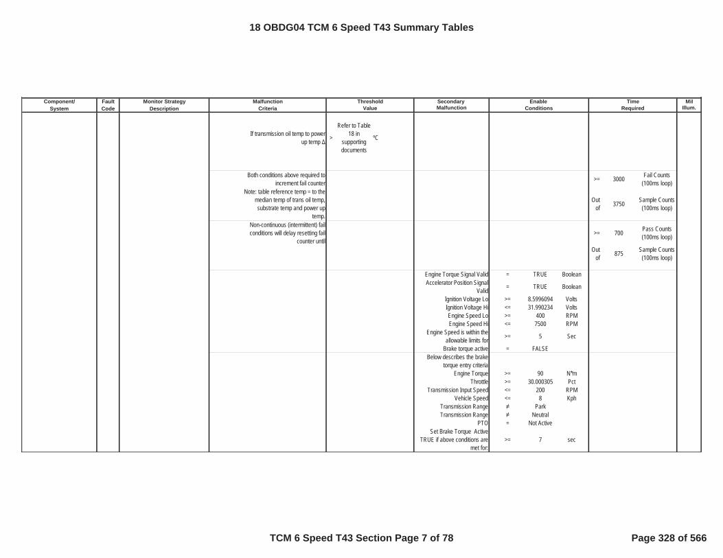
Component/ Fault Monitor Strategy Secondary MilSystem Code Description Malfunction Illum.
Malfunction Threshold Enable TimeCriteria Value Conditions Required
If transmission oil temp to power up temp >
Refer to Table 18 in
supporting documents
ºC
Both conditions above required toincrement fail counter >= 3000 Fail Counts
(100ms loop)Note: table reference temp = to the
median temp of trans oil temp, substrate temp and power up
temp.
Outof 3750 Sample Counts
(100ms loop)
Non-continuous (intermittent) fail conditions will delay resetting fail
counter until>= 700 Pass Counts
(100ms loop)
Out of 875 Sample Counts
(100ms loop)
Engine Torque Signal Valid = TRUE BooleanAccelerator Position Signal
Valid = TRUE Boolean
Ignition Voltage Lo >= 8.5996094 VoltsIgnition Voltage Hi <= 31.990234 VoltsEngine Speed Lo >= 400 RPMEngine Speed Hi <= 7500 RPM
Engine Speed is within the allowable limits for >= 5 Sec
Brake torque active = FALSEBelow describes the brake
torque entry criteriaEngine Torque >= 90 N*m
Throttle >= 30.000305 PctTransmission Input Speed <= 200 RPM
Vehicle Speed <= 8 KphTransmission Range ParkTransmission Range Neutral
PTO = Not ActiveSet Brake Torque Active
TRUE if above conditions are met for:
>= 7 sec
18 OBDG04 TCM 6 Speed T43 Summary Tables
TCM 6 Speed T43 Section Page 7 of 78 Page 328 of 566

Component/ Fault Monitor Strategy Secondary MilSystem Code Description Malfunction Illum.
Malfunction Threshold Enable TimeCriteria Value Conditions Required
Below describes the brake torque exit criteria
Brake torque entry criteria = Not Met
Clutch hydraulic pressure
Clutch Hydraulic Air Purge
Event
Clutch used to exit braketorque active =
CeTFTD_e_C3_RatlE
nblThe above clutch pressure is greater than this value for one
loop>= 600 kpa
Set Brake Torque Active FALSE if above conditions are
met for:>= 20 Sec
P06AC Status is
Test Failed This Key
On or Fault Active
DisableConditions:
MIL not Illuminated forDTC's:
Transmission Control Module (TCM) P06AD TCM power-up thermistor circuit
voltage low Power Up Temp <= -59 ºC >= 60 Fail Time (Sec) TwoTrips
Ignition Voltage Lo >= 8.5996094 VoltsIgnition Voltage Hi <= 31.990234 VoltsEngine Speed Lo >= 400 RPMEngine Speed Hi <= 7500 RPM
TCM: P0658, P0668, P0669, P06AD, P06AE, P0716, P0712, P0713, P0717, P0722, P0723, P0962, P0963, P0966, P0967, P0970, P0971, P215C, P2720, P2721, P2729, P2730
ECM: P0101, P0102, P0103, P0106, P0107, P0108, P0171, P0172, P0174, P0175, P0201, P0202, P0203, P0204, P0205, P0206, P0207, P0208, P0300, P0301, P0302, P0303, P0304, P0305, P0306, P0307, P0308, P0401, P042E
18 OBDG04 TCM 6 Speed T43 Summary Tables
TCM 6 Speed T43 Section Page 8 of 78 Page 329 of 566

Component/ Fault Monitor Strategy Secondary MilSystem Code Description Malfunction Illum.
Malfunction Threshold Enable TimeCriteria Value Conditions Required
Engine Speed is within the allowable limits for >= 5 Sec
P06AD Status is
Test FailedThis Key
On or Fault Active
For Hybrids, below conditions must also be met
Estimated Motor Power Loss >= 0 kWEstimated Motor Power Loss
greater than limit for time >= 0 Sec
Lost Communication withHybrid Processor Control
Module= FALSE
Estimated Motor Power Loss Fault = FALSE
DisableConditions:
MIL not Illuminated forDTC's:
Transmission Control Module (TCM) P06AE TCM power-up thermistor circuit
voltage high Power Up Temp >= 164 ºC >= 60 Fail Time (Sec) TwoTrips
Ignition Voltage Lo >= 8.5996094 VoltsIgnition Voltage Hi <= 31.990234 VoltsEngine Speed Lo >= 400 RPMEngine Speed Hi <= 7500 RPM
Engine Speed is within the allowable limits for >= 5 Sec
P06AE Status is
Test FailedThis Key
On or Fault Active
DisableConditions:
MIL not Illuminated forDTC's:
TCM: P0716, P0717, P0722, P0723
ECM: None
TCM: None
ECM: None
18 OBDG04 TCM 6 Speed T43 Summary Tables
TCM 6 Speed T43 Section Page 9 of 78 Page 330 of 566

Component/ Fault Monitor Strategy Secondary MilSystem Code Description Malfunction Illum.
Malfunction Threshold Enable TimeCriteria Value Conditions Required
Transmission Fluid Temperature Sensor (TFT) P0711 Trans Fluid Temp Sensor Circuit
Range/PerformanceIf transmission oil temp to
substrate temp >
Refer to Table 19 in
supporting documents
ºC
TwoTrips
If transmission oil temp to power up temp >
Refer to Table 18 in
supporting documents
ºC
Both conditions above required toincrement fail counter >= 3000 Fail Counts
(100ms loop)Note: table reference temp = to the
median temp of trans oil temp, substrate temp and power up
temp.
Outof 3750 Sample Counts
(100ms loop)
Non-continuous (intermittent) failconditions will delay resetting fail
counter until>= 700 Pass Counts
(100ms loop)
Out of 875 Sample Counts
(100ms loop)
Engine Torque Signal Valid = TRUE BooleanAccelerator Position Signal
Valid = TRUE Boolean
Ignition Voltage Lo >= 8.5996094 VoltsIgnition Voltage Hi <= 31.990234 VoltsEngine Speed Lo >= 400 RPMEngine Speed Hi <= 7500 RPM
Engine Speed is within theallowable limits for >= 5 Sec
Brake torque active = FALSEBelow describes the brake
torque entry criteriaEngine Torque >= 90 N*m
Throttle >= 30.000305 PctTransmission Input Speed <= 200 RPM
Vehicle Speed <= 8 KphTransmission Range ParkTransmission Range Neutral
PTO = Not Active
18 OBDG04 TCM 6 Speed T43 Summary Tables
TCM 6 Speed T43 Section Page 10 of 78 Page 331 of 566

Component/ Fault Monitor Strategy Secondary MilSystem Code Description Malfunction Illum.
Malfunction Threshold Enable TimeCriteria Value Conditions Required
Set Brake Torque Active TRUE if above conditions are
met for:>= 7 sec
Below describes the brake torque exit criteria
Brake torque entry criteria = Not Met
Clutch hydraulic pressure
Clutch Hydraulic Air Purge
Event
Clutch used to exit braketorque active =
CeTFTD_e_C3_RatlE
nblThe above clutch pressure is greater than this value for one
loop>= 600 kpa
Set Brake Torque Active FALSE if above conditions are
met for:>= 20 Sec
P0711 Status is
Test Failed This Key
On or Fault Active
DisableConditions:
MIL not Illuminated forDTC's:
Transmission Fluid Temperature Sensor (TFT) P0712 Transmission fluid temperature
thermistor failed at a low voltage Type of Sensor Used =CeTFTI_e_VoltageDirectPro
p
TwoTrips
TCM: P0658, P0668, P0669, P06AD, P06AE, P0716, P0712, P0713, P0717, P0722, P0723, P0962, P0963, P0966, P0967, P0970, P0971, P215C, P2720, P2721, P2729, P2730
ECM: P0101, P0102, P0103, P0106, P0107, P0108, P0171, P0172, P0174, P0175, P0201, P0202, P0203, P0204, P0205, P0206, P0207, P0208, P0300, P0301, P0302, P0303, P0304, P0305, P0306, P0307, P0308, P0401, P042E
18 OBDG04 TCM 6 Speed T43 Summary Tables
TCM 6 Speed T43 Section Page 11 of 78 Page 332 of 566
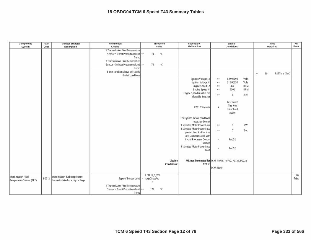
Component/ Fault Monitor Strategy Secondary MilSystem Code Description Malfunction Illum.
Malfunction Threshold Enable TimeCriteria Value Conditions Required
If Transmission Fluid Temperature Sensor = Direct Proportional and
Temp<= -74 ºC
If Transmission Fluid Temperature Sensor = Indirect Proportional and
Temp>= -74 ºC
Either condition above will satisfy the fail conditions >= 60 Fail Time (Sec)
Ignition Voltage Lo >= 8.5996094 VoltsIgnition Voltage Hi <= 31.990234 VoltsEngine Speed Lo >= 400 RPMEngine Speed Hi <= 7500 RPM
Engine Speed is within theallowable limits for >= 5 Sec
P0712 Status is
Test FailedThis Key
On or Fault Active
For Hybrids, below conditionsmust also be met
Estimated Motor Power Loss >= 0 kWEstimated Motor Power Loss
greater than limit for time >= 0 Sec
Lost Communication with Hybrid Processor Control
Module= FALSE
Estimated Motor Power Loss Fault = FALSE
DisableConditions:
MIL not Illuminated forDTC's:
Transmission Fluid Temperature Sensor (TFT) P0713 Transmission fluid temperature
thermistor failed at a high voltage Type of Sensor Used =CeTFTI_e_VoltageDirectPro
p
TwoTrips
If Transmission Fluid TemperatureSensor = Direct Proportional and
Temp>= 174 ºC
TCM: P0716, P0717, P0722, P0723
ECM: None
18 OBDG04 TCM 6 Speed T43 Summary Tables
TCM 6 Speed T43 Section Page 12 of 78 Page 333 of 566

Component/ Fault Monitor Strategy Secondary MilSystem Code Description Malfunction Illum.
Malfunction Threshold Enable TimeCriteria Value Conditions Required
If Transmission Fluid Temperature Sensor = Indirect Proportional and
Temp<= 174 ºC
Either condition above will satisfy the fail conditions >= 60 Fail Time (Sec)
Ignition Voltage Lo >= 8.5996094 VoltsIgnition Voltage Hi <= 31.990234 VoltsEngine Speed Lo >= 400 RPMEngine Speed Hi <= 7500 RPM
Engine Speed is within the allowable limits for >= 5 Sec
P0713 Status is
Test FailedThis Key
On or Fault Active
DisableConditions:
MIL not Illuminated forDTC's:
Transmission Input Speed Sensor (TISS) P0716 Input Speed Sensor Performance Transmission Input Speed Sensor
Drops >= 1350 RPM >= 0.8 Fail Time (Sec) One Trip
Engine Torque is >= 0 N*mEngine Torque is <= 8191.875 N*m
Engine Speed >= 400 RPMEngine Speed <= 7500 RPM
Engine Speed is within the allowable limits for >= 5 Sec
Vehicle Speed is >= 10 KphThrottle Position is >= 0 Pct
--------------Transmission Input Speed is >= 0 RPM
The previous requirement has been satisfied for >= 0 Sec
--------------The change (loop to loop) in transmission input speed is < 8191.875 RPM/Loop
TCM: P0713, P0716, P0717, P0722, P0723
ECM: None
18 OBDG04 TCM 6 Speed T43 Summary Tables
TCM 6 Speed T43 Section Page 13 of 78 Page 334 of 566

Component/ Fault Monitor Strategy Secondary MilSystem Code Description Malfunction Illum.
Malfunction Threshold Enable TimeCriteria Value Conditions Required
The previous requirement has been satisfied for >= 0 Sec
Throttle Position Signal Valid = TRUE BooleanEngine Torque Signal Valid = TRUE Boolean
Ignition Voltage >= 8.5996094 VoltsIgnition Voltage <= 31.990234 Volts
P0716 Status is not =
Test Failed This Key
On or Fault Active
DisableConditions:
MIL not Illuminated forDTC's:
Transmission Input Speed Sensor (TISS) P0717 Input Speed Sensor Circuit Low
VoltageFail Case 1 Transmission Input Speed is < 33 RPM >= 4.5 Fail Time (Sec) One Trip
Fail Case 2 When P0722 DTC Status equal to Test Failed and Transmission Input
Speed is< 1000 RPM Controller uses a single power
supply for the speed sensors = 1 Boolean
Engine Torque is >= 50 N*mEngine Torque is <= 8191.875 N*m
Vehicle Speed >= 16 KphEngine Torque Signal Valid = TRUE Boolean
Ignition Voltage >= 8.5996094 VoltsIgnition Voltage <= 31.990234 Volts
Engine Speed >= 400 RPMEngine Speed <= 7500 RPM
Engine Speed is within theallowable limits for >= 5 Sec
P0717 Status is not =
Test FailedThis Key
On or Fault Active
TCM: P0717, P0752, P0973, P0974
ECM: P0101, P0102, P0103, P0121, P0122, P0123
18 OBDG04 TCM 6 Speed T43 Summary Tables
TCM 6 Speed T43 Section Page 14 of 78 Page 335 of 566

Component/ Fault Monitor Strategy Secondary MilSystem Code Description Malfunction Illum.
Malfunction Threshold Enable TimeCriteria Value Conditions Required
DisableConditions:
MIL not Illuminated forDTC's:
Mode Switch P071A Transmission Mode Switch A Circuit Tow Haul Mode Switch state = TRUE Boolean >= 600 Fail Time (Sec) Special No MIL
Ignition Voltage Lo >= 8.5996094 VoltsIgnition Voltage Hi <= 31.990234 VoltsEngine Speed Lo >= 400 RPMEngine Speed Hi <= 7500 RPM
Engine Speed is within the allowable limits for >= 5 Sec
DisableConditions:
MIL not Illuminated forDTC's:
Transmission Output Speed Sensor (TOSS) P0722 Output Speed Sensor Circuit Low
VoltageTransmission Output Speed
Sensor Raw Speed <= 35 RPM >= 3.75 Fail Time (Sec) One Trip
P0722 Status is not =
Test Failed This Key
On or Fault Active
Transmission Input Speed Check = TRUE Boolean
Engine Torque Check = TRUE BooleanThrottle Position >= 8.0001831 Pct
Transmission Fluid Temperature >= -40 ºC
Disable this DTC if the PTO is active = 1 Boolean
Engine Torque Signal Valid = TRUE BooleanThrottle Position Signal Valid = TRUE Boolean
Ignition Voltage is >= 8.5996094 VoltsIgnition Voltage is <= 31.990234 Volts
Engine Speed is >= 400 RPMEngine Speed is <= 7500 RPM
Engine Speed is within theallowable limits for >= 5 Sec
TCM: P1762
ECM: None
TCM: P0722, P0723
ECM: P0101, P0102, P0103
18 OBDG04 TCM 6 Speed T43 Summary Tables
TCM 6 Speed T43 Section Page 15 of 78 Page 336 of 566

Component/ Fault Monitor Strategy Secondary MilSystem Code Description Malfunction Illum.
Malfunction Threshold Enable TimeCriteria Value Conditions Required
Enable_Flags Defined Below
The Engine Torque Check is TRUE, if either of the two
following conditions are TRUE
Engine Torque Condition 1
Range Shift StatusRange
shift completed
ENUM
OR
Transmission Range is = Park or Neutral
Engine Torque is >= 8191.75 N*mEngine Torque is <= 8191.75 N*m
Engine Torque Condition 2Engine Torque is >= 35 N*mEngine Torque is <= 8191.75 N*m----------------------
The Transmission Input Speed (TIS) Check is TRUE, if either of the two following conditions
are TRUE
TIS Check Condition 1Transmission Input Speed is >= 1000 RPMTransmission Input Speed is <= 8191 RPM
TIS Check Condition 2Engine Speed without the
brake applied is >= 3200 RPM
Engine Speed with the brake applied is >= 3200 RPM
Engine Speed is <= 8191 RPMController uses a single power
supply for the speed sensors = 1 Boolean
Powertrain Brake Pedal is Valid = TRUE Boolean
18 OBDG04 TCM 6 Speed T43 Summary Tables
TCM 6 Speed T43 Section Page 16 of 78 Page 337 of 566

Component/ Fault Monitor Strategy Secondary MilSystem Code Description Malfunction Illum.
Malfunction Threshold Enable TimeCriteria Value Conditions Required
DisableConditions:
MIL not Illuminated forDTC's:
Transmission Output Speed Sensor (TOSS) P0723 Output Speed Sensor Circuit
IntermittentTransmission Output Speed
Sensor Raw Speed >= 105 RPM >= 0.2 Enable Time (Sec)
One Trip
Output Speed Delta <= 8191 RPM >= 0 Enable Time (Sec)
Output Speed Drop > 650 RPM >= 1.5Output Speed Drop Recovery Fail Time (Sec)
AND
Transmission Range is = Driven range (R,D)
----------------------Range_Disable = FALSE See Below
OR----------------------
Neutral_Range_Enable = TRUE See BelowAnd
Neutral_Speed_Enable = TRUE See Beloware TRUE concurrently
----------------------Transmission_Range_Enable = TRUE See Below
Transmission_Input_Speed_Enable = TRUE See Below
No Change in Transfer Case Range (High <-> Low) for >= 5 Seconds
P0723 Status is not =
Test Failed This Key
On or Fault Active
Disable this DTC if the PTO is active = 1 Boolean
Ignition Voltage is >= 8.5996094 VoltsIgnition Voltage is <= 31.990234 Volts
Engine Speed is >= 400 RPMEngine Speed is <= 7500 RPM
Engine Speed is within the allowable limits for >= 5 Sec
TCM: P0716, P0717, P0723
ECM: P0101, P0102, P0103, P0121, P0122, P0123
18 OBDG04 TCM 6 Speed T43 Summary Tables
TCM 6 Speed T43 Section Page 17 of 78 Page 338 of 566

Component/ Fault Monitor Strategy Secondary MilSystem Code Description Malfunction Illum.
Malfunction Threshold Enable TimeCriteria Value Conditions Required
Enable_Flags Defined Below
Transmission_Input_Speed_Enable is TRUE when either TIS Condition 1 or TIS Condition 2
is TRUE:
TIS Condition 1 is TRUE whenboth of the following conditions
are satsified for >= 0 Enable Time
(Sec)
Input Speed Delta <= 4095 RPMRaw Input Speed >= 500 RPM
TIS Condition 2 is TRUE when ALL of the next two conditions
are satisfiedInput Speed = 0 RPM
A Single Power Supply is used for all speed sensors = TRUE Boolean
----------------------Neutral_Range_Enable is
TRUE when any of the next 3 conditions are TRUE
Transmission Range is = Neutral ENUM
Transmission Range is =Reverse/N
eutral Transitonal
ENUM
Transmission Range is =
Neutral/Drive
Transitional
ENUM
And when a drop occurs
Loop to Loop Drop ofTransmission Output Speed is > 650 RPM
----------------------Range_Disable is TRUE when
any of the next three conditions are TRUE
Transmission Range is = Park ENUM
18 OBDG04 TCM 6 Speed T43 Summary Tables
TCM 6 Speed T43 Section Page 18 of 78 Page 339 of 566

Component/ Fault Monitor Strategy Secondary MilSystem Code Description Malfunction Illum.
Malfunction Threshold Enable TimeCriteria Value Conditions Required
Transmission Range is =Park/Rever
se Transitonal
ENUM
Input Clutch is not = ON (Fully Applied) ENUM
----------------------Neutral_Speed_Enable is
TRUE when All of the next three conditions are satsified
for
> 1.5 Seconds
Transmission Output Speed > 130 RPM
The loop to loop change of the Transmission Output Speed is < 20 RPM
The loop to loop change of theTransmission Output Speed is > -10 RPM
----------------------Transmission_Range_Enable is TRUE when one of the next
six conditions is TRUETransmission Range is = Neutral ENUM
Transmission Range is =
Reverse/Neutral
Transitional
ENUM
Transmission Range is =
Neutral/Drive
Transitional
ENUM
Time since a driven range(R,D) has been selected >=
Table Based Time
Please Refer to
Table 21 insupporting documents
Sec
18 OBDG04 TCM 6 Speed T43 Summary Tables
TCM 6 Speed T43 Section Page 19 of 78 Page 340 of 566

Component/ Fault Monitor Strategy Secondary MilSystem Code Description Malfunction Illum.
Malfunction Threshold Enable TimeCriteria Value Conditions Required
Transmission Output Speed Sensor Raw Speed >= 500 RPM
Output Speed when a faultwas detected >= 500 RPM
DisableConditions:
MIL not Illuminated forDTC's:
Torque Converter Clutch (TCC) P0741 TCC System Stuck OFF TCC Pressure >= 750 Kpa >= 2 Enable Time (Sec)
TwoTrips
Either Condition (A) or (B) Must be Met
(A) TCC Slip Error @ TCC On Mode >=
Refer to Table 1 in
Supporting Documents
RPM >= 5 Fail Time (Sec)
(B) TCC Slip @ Lock On Mode >= 130 RPM >= 5 Fail Time (Sec)If Above Conditions Have been
Met, and Fail Timer Expired, Increment Fail Counter
>= 2 TCC Stuck Off Fail Counter
TCC Mode = On or Lock
Ignition Voltage Lo >= 8.5996094 VoltsIgnition Voltage Hi <= 31.990234 Volts
Engine Speed >= 400 RPMEngine Speed <= 7500 RPM
Engine Speed is within theallowable limits for >= 5 Sec
Engine Torque Lo >= 50 N*mEngine Torque Hi <= 8191.875 N*m
Throttle Position Lo >= 8.0001831 PctThrottle Position Hi <= 99.998474 Pct2nd Gear Ratio Lo >= 2.6710205 Ratio
2nd Gear Ratio High <= 3.072998 Ratio3rd Gear Ratio Lo >= 1.7130127 Ratio
3rd Gear Ratio High <= 1.9709473 Ratio4th Gear Ratio Lo >= 1.3150635 Ratio
4th Gear Ratio High <= 1.5129395 Ratio
TCM: P0973, P0974, P0976, P0977
ECM: P0101, P0102, P0103, P0121, P0122, P0123
18 OBDG04 TCM 6 Speed T43 Summary Tables
TCM 6 Speed T43 Section Page 20 of 78 Page 341 of 566
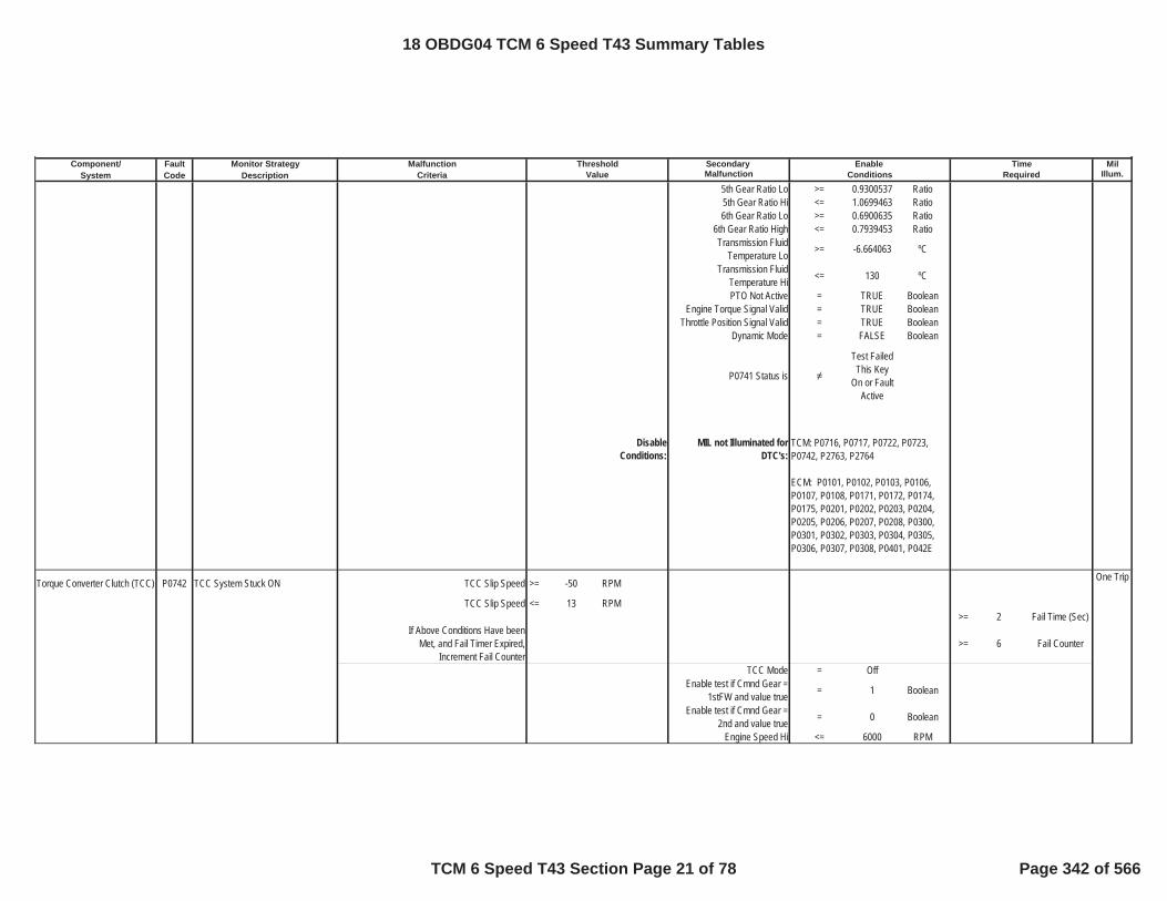
Component/ Fault Monitor Strategy Secondary MilSystem Code Description Malfunction Illum.
Malfunction Threshold Enable TimeCriteria Value Conditions Required
5th Gear Ratio Lo >= 0.9300537 Ratio5th Gear Ratio Hi <= 1.0699463 Ratio6th Gear Ratio Lo >= 0.6900635 Ratio
6th Gear Ratio High <= 0.7939453 RatioTransmission Fluid
Temperature Lo >= -6.664063 ºC
Transmission Fluid Temperature Hi <= 130 ºC
PTO Not Active = TRUE BooleanEngine Torque Signal Valid = TRUE Boolean
Throttle Position Signal Valid = TRUE BooleanDynamic Mode = FALSE Boolean
P0741 Status is
Test Failed This Key
On or Fault Active
DisableConditions:
MIL not Illuminated forDTC's:
Torque Converter Clutch (TCC) P0742 TCC System Stuck ON TCC Slip Speed >= -50 RPM One Trip
TCC Slip Speed <= 13 RPM>= 2 Fail Time (Sec)
If Above Conditions Have been Met, and Fail Timer Expired,
Increment Fail Counter>= 6 Fail Counter
TCC Mode = OffEnable test if Cmnd Gear =
1stFW and value true = 1 Boolean
Enable test if Cmnd Gear = 2nd and value true = 0 Boolean
Engine Speed Hi <= 6000 RPM
TCM: P0716, P0717, P0722, P0723, P0742, P2763, P2764
ECM: P0101, P0102, P0103, P0106, P0107, P0108, P0171, P0172, P0174, P0175, P0201, P0202, P0203, P0204, P0205, P0206, P0207, P0208, P0300, P0301, P0302, P0303, P0304, P0305, P0306, P0307, P0308, P0401, P042E
18 OBDG04 TCM 6 Speed T43 Summary Tables
TCM 6 Speed T43 Section Page 21 of 78 Page 342 of 566

Component/ Fault Monitor Strategy Secondary MilSystem Code Description Malfunction Illum.
Malfunction Threshold Enable TimeCriteria Value Conditions Required
Engine Speed Lo >= 500 RPMVehicle Speed HI <= 511 KPHVehicle Speed Lo >= 1 KPHEngine Torque Hi <= 8191.875 NmEngine Torque Lo >= 80 Nm
Current Range Neutral RangeCurrent Range Reverse Range
Transmission Sump Temperature <= 130 ºC
Transmission SumpTemperature >= 18 ºC
Throttle Position Hyst High >= 5.0003052 PctAND
Max Vehicle Speed to Meet Throttle Enable <= 8 KPH
Once Hyst High has been met, the enable will remain while
Throttle Position>= 2.0004272 Pct
Disable for Throttle Position >= 75 PctDisable if PTO active and
value true = 1 Boolean
Disable if in D1 and value true = 1 BooleanDisable if in D2 and value true = 1 BooleanDisable if in D3 and value true = 1 BooleanDisable if in D4 and value true = 1 BooleanDisable if in D5 and value true = 1 BooleanDisable if in MUMD and value
true = 1 Boolean
Disable if in TUTD and valuetrue = 1 Boolean
4 Wheel Drive Low Active = FALSE BooleanDisable if Air Purge active and
value false = 0 Boolean
RVT Diagnostic Active = FALSE BooleanIgnition Voltage >= 8.5996094 VIgnition Voltage <= 31.990234 VVehicle Speed <= 511 KPHEngine Speed >= 400 RPMEngine Speed <= 7500 RPM
Engine Speed is within theallowable limits for >= 5 Sec
Engine Torque Signal Valid = TRUE Boolean
18 OBDG04 TCM 6 Speed T43 Summary Tables
TCM 6 Speed T43 Section Page 22 of 78 Page 343 of 566

Component/ Fault Monitor Strategy Secondary MilSystem Code Description Malfunction Illum.
Malfunction Threshold Enable TimeCriteria Value Conditions Required
Throttle Position Signal Valid = TRUE Boolean
P0742 Status is
Test Failed This Key
On or Fault Active
DisableConditions:
MIL not Illuminated forDTC's:
Mode 2 Multiplex Valve P0751 Shift Solenoid Valve A Stuck Off Commaned Gear Slip >= 400 RPM TwoTrips
Commanded Gear = 1st Lock rpmGear Ratio <= 1.484985352 >= 0.3 Fail TmrGear Ratio >= 1.343017578 = 5 Fail Counts
If the above parameters are true
0 Neutral Timer (Sec)
>= 0.3 Fail Timer (Sec)
>= 8 CountsIgnition Voltage Lo >= 8.5996094 VoltsIgnition Voltage Hi <= 31.990234 VoltsEngine Speed Lo >= 400 RPMEngine Speed Hi <= 7500 RPM
Engine Speed is within theallowable limits for >= 5 Sec
Transmission Fluid Temperature >= -6.65625 ºC
Range Shift State =RangeShift
CompletedENUM
TCM: P0716, P0717, P0722, P0723, P0741, P2763, P2764
ECM: P0101, P0102, P0103, P0106, P0107, P0108, P0171, P0172, P0174, P0175, P0201, P0202, P0203, P0204, P0205, P0206, P0207, P0208, P0300, P0301, P0302, P0303, P0304, P0305, P0306, P0307, P0308, P0401, P042E
18 OBDG04 TCM 6 Speed T43 Summary Tables
TCM 6 Speed T43 Section Page 23 of 78 Page 344 of 566

Component/ Fault Monitor Strategy Secondary MilSystem Code Description Malfunction Illum.
Malfunction Threshold Enable TimeCriteria Value Conditions Required
TPS >= 0.5004883 %OR
Output Speed >= 36 RPMThrottle Position Signal Valid
from ECM = TRUE Boolean
Engine Torque Signal Valid from ECM, High side driver is
enabled= TRUE Boolean
High-Side Driver is Enabled = TRUE BooleanInput Speed Sensor fault = FALSE Boolean
Output Speed Sensor fault = FALSE BooleanDefault Gear Option is not
present = TRUE
DisableConditions:
MIL not Illuminated forDTC's:
Mode 2 Multiplex Valve P0752 Shift Solenoid Valve A Stuck On Gear Box Slip >= 400 RPM One Trip
Commanded Gear = 3rd GearCommanded Gear has Achieved
1st Locked OR 1st Free-Wheel OR 2nd with Mode 2 Sol. Commanded
On
= TRUE Boolean
If the above parameters are true
>=
Please Refer to Table 16 in
Supporting Documents
Neutral Timer (Sec)
Command 4th Gear once Output Shaft Speed <= 800 RPM
If Gear Ratio >= 4.259765625And Gear Ratio <= 4.708251953
TCM: P0716, P0717, P0722, P0723, P182E
ECM: P0101, P0102, P0103, P0106, P0107, P0108, P0171, P0172, P0174, P0175, P0201, P0202, P0203, P0204, P0205, P0206, P0207, P0208, P0300, P0301, P0302, P0303, P0304, P0305, P0306, P0307, P0308, P0401, P042E
18 OBDG04 TCM 6 Speed T43 Summary Tables
TCM 6 Speed T43 Section Page 24 of 78 Page 345 of 566

Component/ Fault Monitor Strategy Secondary MilSystem Code Description Malfunction Illum.
Malfunction Threshold Enable TimeCriteria Value Conditions Required
>= 1.5 Fail Timer (Sec)
>= 5 CountsIgnition Voltage Lo >= 8.5996094 VoltsIgnition Voltage Hi <= 31.990234 VoltsEngine Speed Lo >= 400 RPMEngine Speed Hi <= 7500 RPM
Engine Speed is within the allowable limits for >= 5 Sec
High-Side Driver is Enabled = TRUE BooleanThrottle Position Signal Valid
from ECM = TRUE Boolean
Output Speed >= 36 RPMOR
TPS >= 0.5004883 %
Range Shift State =RangeShift
CompletedENUM
Transmission Fluid Temperature >= -6.65625 ºC
Input Speed Sensor fault = FALSE BooleanOutput Speed Sensor fault = FALSE BooleanDefault Gear Option is not
present = TRUE
DisableConditions:
MIL not Illuminated forDTC's:
Mode 2 Multiplex Valve P0756 Shift Solenoid Valve B Stuck Off Fail Case 1 Commanded Gear = 1st Locked One Trip
TCM: P0716, P0717, P0722, P0723, P182E
ECM: P0101, P0102, P0103, P0106, P0107, P0108, P0171, P0172, P0174, P0175, P0201, P0202, P0203, P0204, P0205, P0206, P0207, P0208, P0300, P0301, P0302, P0303, P0304, P0305, P0306, P0307, P0308, P0401, P042E
18 OBDG04 TCM 6 Speed T43 Summary Tables
TCM 6 Speed T43 Section Page 25 of 78 Page 346 of 566

Component/ Fault Monitor Strategy Secondary MilSystem Code Description Malfunction Illum.
Malfunction Threshold Enable TimeCriteria Value Conditions Required
Gear Box Slip >= 400 RPM >=
Please Refer to Table 5 in Supporting Documents
Neutral Timer (Sec)
Intrusive Shift to 2ndCommanded Gear Previous = 1st Locked Gear
Gear Ratio <= 3.015991211Gear Ratio >= 2.728027344
If the above parameters are true>= 1 sec>= 3 counts
Ignition Voltage Lo >= 8.5996094 VoltsIgnition Voltage Hi <= 31.990234 VoltsEngine Speed Lo >= 400 RPMEngine Speed Hi <= 7500 RPM
Engine Speed is within the allowable limits for >= 5 Sec
Output Speed >= 36 RPMOR
TPS >= 0.5004883 %
Range Shift State =RangeShift
CompletedENUM
Transmission FluidTemperature >= -6.65625 ºC
High-Side Driver is Enabled = TRUE BooleanThrottle Position Signal Valid
from ECM = TRUE Boolean
Input Speed Sensor fault = FALSE BooleanOutput Speed Sensor fault = FALSE BooleanDefault Gear Option is not
present = TRUE
18 OBDG04 TCM 6 Speed T43 Summary Tables
TCM 6 Speed T43 Section Page 26 of 78 Page 347 of 566

Component/ Fault Monitor Strategy Secondary MilSystem Code Description Malfunction Illum.
Malfunction Threshold Enable TimeCriteria Value Conditions Required
DisableConditions:
MIL not Illuminated forDTC's:
Variable Bleed Solenoid (VBS) P0776 Pressure Control (PC) Solenoid B Stuck Off [C35R]
Fail Case 1 Case: Steady State 3rd Gear One Trip
Commanded Gear = 3rd GearGearbox Slip >= 400 RPM
>=
Please Refer to Table 16 in
Supporting Documents
Neutral Timer (Sec)
Command 4th Gear once OutputShaft Speed <= 800 RPM
If Gear Ratio >= 1.343261719And Gear Ratio <= 1.484741211
>= 3 Fail Timer (Sec)
It the above condiations are true, Increment 3rd gear fail counter >= 3 3rd Gear Fail
Countsor
and C35R Fail counter >= 14 3-5R Clutch Fail Counts
Fail Case 2 Case: Steady State 5th GearCommanded Gear = 5th Gear
Gearbox Slip >= 400 Rpm >=
Please Refer to Table 5 in Supporting Documents
Neutral Timer (Sec)
Intrusive Test: Command 6th Gear
TCM: P0716, P0717, P0722, P0723, P182E
ECM: P0101, P0102, P0103, P0106, P0107, P0108, P0171, P0172, P0174, P0175, P0201, P0202, P0203, P0204, P0205, P0206, P0207, P0208, P0300, P0301, P0302, P0303, P0304, P0305, P0306, P0307, P0308, P0401, P042E
18 OBDG04 TCM 6 Speed T43 Summary Tables
TCM 6 Speed T43 Section Page 27 of 78 Page 348 of 566

Component/ Fault Monitor Strategy Secondary MilSystem Code Description Malfunction Illum.
Malfunction Threshold Enable TimeCriteria Value Conditions Required
If attained Gear=6th gear Time >=
Please refer toTable 3 in supporting documents
Shift Time (Sec)
It the above condiations are true,Increment 5th gear fail counter >= 3 5th Gear Fail
Countsor
and C35R Fail counter >= 14 3-5R Clutch FailCounts
PRNDL State defaulted = FALSE Booleaninhibit RVT = FALSE Boolean
IMS fault pending indication = FALSE BooleanTPS validity flag = TRUE Boolean
Hydraulic System Pressurized = TRUE Boolean
Minimum output speed for RVT >= 36 RPM
A OR B(A) Output speed enable >= 36 RPM
(B) Accelerator Pedal enable >= 0.5004883 PctCommon Enable Criteria
Ignition Voltage Lo >= 8.5996094 VoltsIgnition Voltage Hi <= 31.990234 VoltsEngine Speed Lo >= 400 RPMEngine Speed Hi <= 7500 RPM
Engine Speed is within theallowable limits for >= 5 Sec
Throttle Position Signal valid = TRUE BooleanHSD Enabled = TRUE Boolean
Transmission Fluid Temperature >= -6.65625 ºC
Input Speed Sensor fault = FALSE BooleanOutput Speed Sensor fault = FALSE BooleanDefault Gear Option is not
present = TRUE
18 OBDG04 TCM 6 Speed T43 Summary Tables
TCM 6 Speed T43 Section Page 28 of 78 Page 349 of 566

Component/ Fault Monitor Strategy Secondary MilSystem Code Description Malfunction Illum.
Malfunction Threshold Enable TimeCriteria Value Conditions Required
DisableConditions:
MIL not Illuminated forDTC's:
Variable Bleed Solenoid (VBS) P0777 Pressure Control (PC) Solinoid B Stuck On [C35R] (Steady State)
Fail Case 1 Case: Steady State 1st One Trip
Attained Gear slip >= 400 RPM
If the Above is True for Time >=
Table Based Time Please
Refer to Table 4 in
supporting documents
Enable Time (Sec)
Intrusive test:(CBR1 clutch exhausted)
Gear Ratio <= 1.933959961Gear Ratio >= 1.75
If the above parameters are true
>= 1.1 Fail Timer (Sec)
>= 2 Fail Count in 1stGear
or
>= 3 Total Fail Counts
Fail Case 2 Case: Steady State 2nd gear
Max Delta Output Speed Hysteresis >=
Table Based value Please
Refer to Table 22 in
supporting documents
rpm/sec
TCM: P0716, P0717, P0722, P0723, P182E
ECM: P0101, P0102, P0103, P0106, P0107, P0108, P0171, P0172, P0174, P0175, P0201, P0202, P0203, P0204, P0205, P0206, P0207, P0208, P0300, P0301, P0302, P0303, P0304, P0305, P0306, P0307, P0308, P0401, P042E
18 OBDG04 TCM 6 Speed T43 Summary Tables
TCM 6 Speed T43 Section Page 29 of 78 Page 350 of 566

Component/ Fault Monitor Strategy Secondary MilSystem Code Description Malfunction Illum.
Malfunction Threshold Enable TimeCriteria Value Conditions Required
Min Delta Output Speed Hysteresis >=
Table Based value Please
Refer to Table 23 in
supporting documents
rpm/sec
If the Above is True for Time >=
Table Based Time Please
Refer to Table 17 in
supporting documents
Sec
Intrusive test: (CB26 clutch exhausted)
Gear Ratio <= 1.933959961Gear Ratio >= 1.75
If the above parameters are true
>= 1.1 Fail Timer (Sec)
>= 3 Fail Count in 2nd Gear
or
>= 3 Total Fail Counts
Fail Case 3 Case: Steady State 4th gear
Max Delta Output Speed Hysteresis >=
Table Based value Please
Refer to Table 22 in
supporting documents
rpm/sec
Min Delta Output Speed Hysteresis >=
Table Based value Please
Refer to Table 23 in
supporting documents
rpm/sec
18 OBDG04 TCM 6 Speed T43 Summary Tables
TCM 6 Speed T43 Section Page 30 of 78 Page 351 of 566
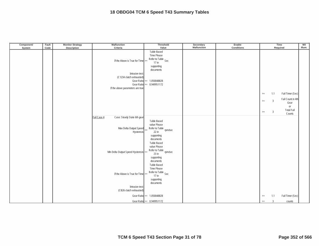
Component/ Fault Monitor Strategy Secondary MilSystem Code Description Malfunction Illum.
Malfunction Threshold Enable TimeCriteria Value Conditions Required
If the Above is True for Time >=
Table Based Time Please
Refer to Table 17 in
supporting documents
Sec
Intrusive test: (C1234 clutch exhausted)
Gear Ratio <= 1.050048828Gear Ratio >= 0.949951172
If the above parameters are true
>= 1.1 Fail Timer (Sec)
>= 3 Fail Count in 4thGear
or
>= 3 Total Fail Counts
Fail Case 4 Case: Steady State 6th gear
Max Delta Output Speed Hysteresis >=
Table Based value Please
Refer to Table 22 in
supporting documents
rpm/sec
Min Delta Output Speed Hysteresis >=
Table Based value Please
Refer to Table 23 in
supporting documents
rpm/sec
If the Above is True for Time >=
Table Based Time Please
Refer to Table 17 in
supporting documents
Sec
Intrusive test: (CB26 clutch exhausted)
Gear Ratio <= 1.050048828 >= 1.1 Fail Timer (Sec)
Gear Ratio >= 0.949951172 >= 3 counts
18 OBDG04 TCM 6 Speed T43 Summary Tables
TCM 6 Speed T43 Section Page 31 of 78 Page 352 of 566

Component/ Fault Monitor Strategy Secondary MilSystem Code Description Malfunction Illum.
Malfunction Threshold Enable TimeCriteria Value Conditions Required
If the above parameters are true
>= 1.1 Fail Timer (Sec)
>= 3 Fail Count in 6th Gear
or
>= 3 Total Fail Counts
PRNDL State defaulted = FALSE Booleaninhibit RVT = FALSE Boolean
IMS fault pending indication = FALSE Booleanoutput speed >= 0 RPM
TPS validity flag = TRUE BooleanHSD Enabled = TRUE Boolean
Hydraulic_System_Pressurized = TRUE Boolean
A OR B(A) Output speed enable >= 36 Nm
(B) Accelerator Pedal enable >= 0.5004883 NmIgnition Voltage Lo >= 8.5996094 VoltsIgnition Voltage Hi <= 31.990234 VoltsEngine Speed Lo >= 400 RPMEngine Speed Hi <= 7500 RPM
Engine Speed is within the allowable limits for >= 5 Sec
if Attained Gear=1st FW Accelerator Pedal enable >= 5.0003052 Pct
if Attained Gear=1st FW Engine Torque Enable >= 20 Nm
if Attained Gear=1st FW Engine Torque Enable <= 8191.875 Nm
Transmission FluidTemperature >= -6.65625 ºC
Input Speed Sensor fault = FALSE BooleanOutput Speed Sensor fault = FALSE Boolean
18 OBDG04 TCM 6 Speed T43 Summary Tables
TCM 6 Speed T43 Section Page 32 of 78 Page 353 of 566

Component/ Fault Monitor Strategy Secondary MilSystem Code Description Malfunction Illum.
Malfunction Threshold Enable TimeCriteria Value Conditions Required
DisableConditions:
MIL not Illuminated forDTC's:
Variable Bleed Solenoid (VBS) P0777 Pressure Control (PC) Solenoid B StuckOn [C35R] (Dymanic)
Primary Offgoing Clutch is exhausted (See Table 12 in
Supporting Documents for Exhaust Delay Timers)
= TRUE Boolean
One Trip
Primary Oncoming Clutch Pressure Command Status = Maximum
pressurized
Primary Offgoing Clutch PressureCommand Status =
Clutch exhaust
command
Range Shift Status Initial Clutch Control
Attained Gear Slip <= 40 RPM
If the above conditions are true runappropriate Fail 1 Timers Below:
fail timer 1(3-1 shifting with Closed Throttle) >= 0.5 Fail Time (Sec)
fail timer 1(3-2 shifting with Throttle) >= 0.5 Fail Time (Sec)
fail timer 1(3-2 shifting with Closed Throttle) >= 0.5 Fail Time (Sec)
fail timer 1(3-4 shifting with Throttle) >= 0.5 Fail Time (Sec)
fail timer 1(3-4shifting with Closed Throttle) >= 0.5 Fail Time (Sec)
fail timer 1(3-5 shifting with Throttle) >= 0.5 Fail Time (Sec)
fail timer 1(3-5 shifting with Closed Throttle) >= 0.5 Fail Time (Sec)
TCM: P0716, P0717, P0722, P0723, P182E
ECM: P0101, P0102, P0103, P0106, P0107, P0108, P0171, P0172, P0174, P0175, P0201, P0202, P0203, P0204, P0205, P0206, P0207, P0208, P0300, P0301, P0302, P0303, P0304, P0305, P0306, P0307, P0308, P0401, P042E
18 OBDG04 TCM 6 Speed T43 Summary Tables
TCM 6 Speed T43 Section Page 33 of 78 Page 354 of 566

Component/ Fault Monitor Strategy Secondary MilSystem Code Description Malfunction Illum.
Malfunction Threshold Enable TimeCriteria Value Conditions Required
fail timer 1(5-3 shifting with Throttle) >= 0.5 Fail Time (Sec)
fail timer 1(5-3 shifting with Closed Throttle) >= 0.5 Fail Time (Sec)
fail timer 1(5-4 shifting with Throttle) >= 0.5 Fail Time (Sec)
fail timer 1(5-4 shifting with Closed Throttle) >= 0.5 Fail Time (Sec)
fail timer 1(5-6 shifting with Throttle) >= 0.5 Fail Time (Sec)
fail timer 1(5-6 shifting with Closed Throttle) >= 0.5 Fail Time (Sec)
If Attained Gear Slip is Less thanAbove Cal Increment Fail Timers >=
Total Fail Time = (Fail 1 + Fail 2) See
Enable Timers for Fail Timer
1, and Reference Supporting Table 15 for Fail Timer 2
sec
If fail timer is greater than thresholdincrement corresponding gear fail
counter and total fail counter
3rd gear fail counter >= 3 3rd gear fail counts
OR
5th gear fail counter >= 5 5th gear fail counts
ORTotal fail counter >= 5 total fail counts
TUT Enable temperature >= -6.65625 ºCInput Speed Sensor fault = FALSE Boolean
Output Speed Sensor fault = FALSE BooleanCommand / Attained Gear 1st Boolean
High Side Driver ON = TRUE Booleanoutput speed limit for TUT >= 100 RPM
input speed limit for TUT >= 200 RPMPRNDL state defaulted = FALSE Boolean
18 OBDG04 TCM 6 Speed T43 Summary Tables
TCM 6 Speed T43 Section Page 34 of 78 Page 355 of 566

Component/ Fault Monitor Strategy Secondary MilSystem Code Description Malfunction Illum.
Malfunction Threshold Enable TimeCriteria Value Conditions Required
IMS Fault Pending = FALSE BooleanService Fast Learn Mode = FALSE Boolean
HSD Enabled = TRUE BooleanDefault Gear Option is not
present = TRUE
DisableConditions:
MIL not Illuminated forDTC's:
Variable Bleed Solenoid (VBS) P0796 Pressure Control (PC) Solenoid C Stuck Off [C456] (Steady State)
Fail Case 1 Case: Steady State 4th Gear One Trip
Gear slip >= 400 RPM >=
Please See Table 5 For
Neutral Time Cal
Neutral Timer (Sec)
Intrusive test:commanded 5th gear
If attained Gear 5th for time >=
Please refer toTable 3 in Supporting Documents
Shift Time (Sec)
if the above conditions have been met
Increment 4th Gear Fail Counter >= 3 4th Gear Fail Count
OR
and C456 Fail Counters >= 14 C456 Fail Counts
Fail Case 2 Case: Steady State 5th Gear
Gear slip >= 400 RPM >=
Please See Table 5 For
Neutral Time Cal
Neutral Timer (Sec)
TCM: P0716, P0717, P0722, P0723, P182E
ECM: P0101, P0102, P0103, P0106, P0107, P0108, P0171, P0172, P0174, P0175, P0201, P0202, P0203, P0204, P0205, P0206, P0207, P0208, P0300, P0301, P0302, P0303, P0304, P0305, P0306, P0307, P0308, P0401, P042E
18 OBDG04 TCM 6 Speed T43 Summary Tables
TCM 6 Speed T43 Section Page 35 of 78 Page 356 of 566

Component/ Fault Monitor Strategy Secondary MilSystem Code Description Malfunction Illum.
Malfunction Threshold Enable TimeCriteria Value Conditions Required
Intrusive test:commanded 6th gear
If attained Gear 6th for time >=
Please Refer to Table 3 in Supporting Documents
Shift Time (Sec)
if the above conditions have beenmet
Increment 5th Gear Fail Counter >= 3 5th Gear Fail Count
OR
and C456 Fail Counters >= 14 C456 Fail Counts
Fail Case 3 Case: Steady State 6th Gear
Gear slip >= 400 RPM >=
Please See Table 5 For
Neutral Time Cal
Neutral Timer (Sec)
Intrusive test:commanded 5th gear
If attained Gear 5th for time >=
Please refer toTable 3 in Supporting Documents
Shift Time (Sec)
if the above conditions have beenmet
Increment 6th Gear Fail Counter and C456 Fail Counter >= 3 6th Gear Fail
CountOR
and C456 Fail Counter >= 14 C456 Fail Counts
PRNDL State defaulted = FALSE Booleaninhibit RVT = FALSE Boolean
IMS fault pending indication = FALSE BooleanTPS validity flag = TRUE Boolean
Hydraulic System Pressurized = TRUE Boolean
Minimum output speed for RVT >= 36 RPM
A OR B(A) Output speed enable >= 36 RPM
(B) Accelerator Pedal enable >= 0.5004883 PctCommon Enable Criteria
18 OBDG04 TCM 6 Speed T43 Summary Tables
TCM 6 Speed T43 Section Page 36 of 78 Page 357 of 566

Component/ Fault Monitor Strategy Secondary MilSystem Code Description Malfunction Illum.
Malfunction Threshold Enable TimeCriteria Value Conditions Required
Ignition Voltage Lo >= 8.5996094 VoltsIgnition Voltage Hi <= 31.990234 VoltsEngine Speed Lo >= 400 RPMEngine Speed Hi <= 7500 RPM
Engine Speed is within the allowable limits for >= 5 Sec
Throttle Position Signal valid = TRUE BooleanHSD Enabled = TRUE Boolean
Transmission Fluid Temperature >= -6.65625 ºC
Input Speed Sensor fault = FALSE BooleanOutputSpeed Sensor fault = FALSE BooleanDefault Gear Option is not
present = TRUE
DisableConditions:
MIL not Illuminated forDTC's:
Variable Bleed Solenoid (VBS) P0797 Pressure Control (PC) Solenoid C Stuck On [C456] (Steady State)
Fail Case 1 Case: Steady State 1st One Trip
Attained Gear slip >= 400 RPM
If the Above is True for Time >=
Table Based Time Please
Refer to Table 4 in
supporting documents
Enable Time (Sec)
Intrusive test:(CBR1 clutch exhausted)
Gear Ratio <= 1.484985352Gear Ratio >= 1.343017578
If the above parameters are true
TCM: P0716, P0717, P0722, P0723, P182E
ECM: P0101, P0102, P0103, P0106, P0107, P0108, P0171, P0172, P0174, P0175, P0201, P0202, P0203, P0204, P0205, P0206, P0207, P0208, P0300, P0301, P0302, P0303, P0304, P0305, P0306, P0307, P0308, P0401, P042E
18 OBDG04 TCM 6 Speed T43 Summary Tables
TCM 6 Speed T43 Section Page 37 of 78 Page 358 of 566

Component/ Fault Monitor Strategy Secondary MilSystem Code Description Malfunction Illum.
Malfunction Threshold Enable TimeCriteria Value Conditions Required
>= 1.1 Fail Timer (Sec)
>= 2 Fail Count in 1st Gear
or
>= 3 Total Fail Counts
Fail Case 2 Case Steady State 2nd
Max Delta Output Speed Hysteresis >=
Table Based value Please
Refer to Table 22 in
supporting documents
rpm/sec
Min Delta Output Speed Hysteresis >=
Table Based value Please
Refer to Table 23 in
supporting documents
rpm/sec
If the Above is True for Time >=
Table Based Time Please
Refer to Table 17 in
supporting documents
Sec
Intrusive test: (CB26 clutch exhausted)
Gear Ratio <= 1.484985352Gear Ratio >= 1.343017578
If the above parameters are true
>= 1.1 Fail Timer (Sec)
>= 3 Fail Count in 2nd Gear
or
>= 3 Total fail counts
Fail Case 3 Case Steady State 3rd
18 OBDG04 TCM 6 Speed T43 Summary Tables
TCM 6 Speed T43 Section Page 38 of 78 Page 359 of 566

Component/ Fault Monitor Strategy Secondary MilSystem Code Description Malfunction Illum.
Malfunction Threshold Enable TimeCriteria Value Conditions Required
Max Delta Output Speed Hysteresis >=
Table Based value Please
Refer to Table 22 in
supporting documents
rpm/sec
Min Delta Output Speed Hysteresis >=
Table Based value Please
Refer to Table 23 in
supporting documents
rpm/sec
If the Above is True for Time >=
Table Based Time Please
Refer to Table 17 in
supporting documents
Sec
Intrusive test: (C35R clutch exhausted)
Gear Ratio <= 1.484985352Gear Ratio >= 1.343017578
If the above parameters are true
>= 1.1 Fail Timer (Sec)
>= 3 Fail Count in 3rd Gear
OR
>= 3 Total Fail Counts
PRNDL State defaulted = FALSE Booleaninhibit RVT = FALSE Boolean
IMS fault pending indication = FALSE Booleanoutput speed >= 0 RPM
TPS validity flag = TRUE BooleanHSD Enabled = TRUE Boolean
Hydraulic_System_Pressurized = TRUE Boolean
A OR B(A) Output speed enable >= 36 Nm
(B) Accelerator Pedal enable >= 0.5004883 NmIgnition Voltage Lo >= 8.5996094 Volts
18 OBDG04 TCM 6 Speed T43 Summary Tables
TCM 6 Speed T43 Section Page 39 of 78 Page 360 of 566

Component/ Fault Monitor Strategy Secondary MilSystem Code Description Malfunction Illum.
Malfunction Threshold Enable TimeCriteria Value Conditions Required
Ignition Voltage Hi <= 31.990234 VoltsEngine Speed Lo >= 400 RPMEngine Speed Hi <= 7500 RPM
Engine Speed is within the allowable limits for >= 5 Sec
if Attained Gear=1st FWAccelerator Pedal enable >= 5.0003052 Pct
if Attained Gear=1st FWEngine Torque Enable >= 20 Nm
if Attained Gear=1st FWEngine Torque Enable <= 8191.875 Nm
Transmission Fluid Temperature >= -6.65625 ºC
Input Speed Sensor fault = FALSE BooleanOutput Speed Sensor fault = FALSE BooleanDefault Gear Option is not
present = TRUE
DisableConditions:
MIL not Illuminated forDTC's:
Variable Bleed Solenoid (VBS) P0797 Pressure Control (PC) Solenoid C Stuck On [C456] (Dynamic)
Primary Offgoing Clutch is exhausted (See Table 11 in
Supporting Documents for Exhaust Delay Timers)
= TRUE Boolean
One Trip
Primary Oncoming Clutch Pressure Command Status = Maximum
pressurized
Primary Offgoing Clutch PressureCommand Status =
Clutch exhaust
command
Range Shift Status Initial Clutch Control
Attained Gear Slip <= 40 RPM
TCM: P0716, P0717, P0722, P0723, P182E
ECM: P0101, P0102, P0103, P0106, P0107, P0108, P0171, P0172, P0174, P0175, P0201, P0202, P0203, P0204, P0205, P0206, P0207, P0208, P0300, P0301, P0302, P0303, P0304, P0305, P0306, P0307, P0308, P0401, P042E
18 OBDG04 TCM 6 Speed T43 Summary Tables
TCM 6 Speed T43 Section Page 40 of 78 Page 361 of 566

Component/ Fault Monitor Strategy Secondary MilSystem Code Description Malfunction Illum.
Malfunction Threshold Enable TimeCriteria Value Conditions Required
If the above conditions are true increment appropriate Fail 1
Timers Below:fail timer 1
(4-1 shifting with throttle) >= 0.5 Fail Time (Sec)
fail timer 1(4-1 shifting without throttle) >= 0.5 Fail Time (Sec)
fail timer 1(4-2 shifting with throttle) >= 0.5 Fail Time (Sec)
fail timer 1(4-2 shifting without throttle) >= 0.5 Fail Time (Sec)
fail timer 1(4-3 shifting with throttle) >= 0.5 Fail Time (Sec)
fail timer 1(4-3 shifting without throttle) >= 0.5 Fail Time (Sec)
fail timer 1(5-3 shifting with throttle) >= 0.5 Fail Time (Sec)
fail timer 1(5-3 shifting without throttle) >= 0.5 Fail Time (Sec)
fail timer 1(6-2 shifting with throttle) >= 0.5 Fail Time (Sec)
fail timer 1(6-2 shifting without throttle) >= 0.5 Fail Time (Sec)
If Attained Gear Slip is Less thanAbove Cal Increment Fail Timers >=
Total Fail Time = (Fail 1 + Fail 2) See
Enable Timersfor Fail Timer
1, and Reference Supporting Table 15 for Fail Timer 2
sec
If fail timer is greater than threshold increment corresponding gear fail
counter and total fail counter
4th gear fail counter >= 3 Fail Counter From 4th Gear
OR
18 OBDG04 TCM 6 Speed T43 Summary Tables
TCM 6 Speed T43 Section Page 41 of 78 Page 362 of 566

Component/ Fault Monitor Strategy Secondary MilSystem Code Description Malfunction Illum.
Malfunction Threshold Enable TimeCriteria Value Conditions Required
5th gear fail counter >= 3 Fail Counter From 5th Gear
OR
6th gear fail counter >= 3 Fail Counter From 6th Gear
OR
Total fail counter >= 5 Total Fail Counter
TUT Enable temperature >= -6.65625 ºCInput Speed Sensor fault = FALSE Boolean
Output Speed Sensor fault = FALSE BooleanCommand / Attained Gear 1st Boolean
High Side Driver ON = TRUE Booleanoutput speed limit for TUT >= 100 RPM
input speed limit for TUT >= 200 RPMPRNDL state defaulted = FALSE Boolean
IMS Fault Pending = FALSE BooleanService Fast Learn Mode = FALSE Boolean
HSD Enabled = TRUE Boolean
DisableConditions:
MIL not Illuminated forDTC's:
Tap Up Tap Down Switch (TUTD) P0815 Upshift Switch Circuit Fail Case 1 Tap Up Switch Stuck in the Up
Position in Range 1 Enabled = 0 Boolean Special No MIL
Tap Up Switch Stuck in the Up Position in Range 2 Enabled = 0 Boolean
Tap Up Switch Stuck in the Up Position in Range 3 Enabled = 0 Boolean
Tap Up Switch Stuck in the Up Position in Range 4 Enabled = 0 Boolean
Tap Up Switch Stuck in the UpPosition in Range 5 Enabled = 0 Boolean
TCM: P0716, P0717, P0722, P0723, P182E
ECM: P0101, P0102, P0103, P0106, P0107, P0108, P0171, P0172, P0174, P0175, P0201, P0202, P0203, P0204, P0205, P0206, P0207, P0208, P0300, P0301, P0302, P0303, P0304, P0305, P0306, P0307, P0308, P0401, P042E
18 OBDG04 TCM 6 Speed T43 Summary Tables
TCM 6 Speed T43 Section Page 42 of 78 Page 363 of 566

Component/ Fault Monitor Strategy Secondary MilSystem Code Description Malfunction Illum.
Malfunction Threshold Enable TimeCriteria Value Conditions Required
Tap Up Switch Stuck in the Up Position in Range 6 Enabled = 0 Boolean
Tap Up Switch Stuck in the UpPosition in Neutral Enabled = 1 Boolean
Tap Up Switch Stuck in the Up Position in Park Enabled = 1 Boolean
Tap Up Switch Stuck in the Up Position in Reverse Enabled = 0 Boolean
Tap Up Switch ON = TRUE Boolean >= 1 Fail Time (Sec)
Fail Case 2 Tap Up Switch Stuck in the Up Position in Range 1 Enabled = 1 Boolean
Tap Up Switch Stuck in the UpPosition in Range 2 Enabled = 1 Boolean
Tap Up Switch Stuck in the UpPosition in Range 3 Enabled = 1 Boolean
Tap Up Switch Stuck in the UpPosition in Range 4 Enabled = 1 Boolean
Tap Up Switch Stuck in the Up Position in Range 5 Enabled = 1 Boolean
Tap Up Switch Stuck in the Up Position in Range 6 Enabled = 1 Boolean
Tap Up Switch Stuck in the Up Position in Neutral Enabled = 0 Boolean
Tap Up Switch Stuck in the Up Position in Park Enabled = 0 Boolean
Tap Up Switch Stuck in the Up Position in Reverse Enabled = 0 Boolean
Tap Up Switch ON = TRUE BooleanNOTE: Both Failcase1 and
Failcase 2 Must Be Met >= 600 Fail Time (Sec)
18 OBDG04 TCM 6 Speed T43 Summary Tables
TCM 6 Speed T43 Section Page 43 of 78 Page 364 of 566

Component/ Fault Monitor Strategy Secondary MilSystem Code Description Malfunction Illum.
Malfunction Threshold Enable TimeCriteria Value Conditions Required
Time Since Last Range Change >= 1 Enable Time
(Sec)Ignition Voltage Lo >= 8.5996094 VoltsIgnition Voltage Hi <= 31.990234 VoltsEngine Speed Lo >= 400 RPMEngine Speed Hi <= 7500 RPM
Engine Speed is within the allowable limits for >= 5 Sec
P0815 Status is
Test FailedThis Key
On or Fault Active
DisableConditions:
MIL not Illuminated forDTC's:
Tap Up Tap Down Switch (TUTD) P0816 Downshift Switch Circuit
Fail Case 1 Tap Down Switch Stuck in the Down Position in Range 1 Enabled = 0 Boolean
Special No MIL
Tap Down Switch Stuck in theDown Position in Range 2 Enabled = 0 Boolean
Tap Down Switch Stuck in theDown Position in Range 3 Enabled = 0 Boolean
Tap Down Switch Stuck in the Down Position in Range 4 Enabled = 0 Boolean
Tap Down Switch Stuck in theDown Position in Range 5 Enabled = 0 Boolean
Tap Down Switch Stuck in the Down Position in Range 6 Enabled = 0 Boolean
Tap Down Switch Stuck in the Down Position in Range Neutral
Enabled= 1 Boolean
TCM: P0816, P0826, P182E, P1876, P1877, P1915, P1761
ECM: None
18 OBDG04 TCM 6 Speed T43 Summary Tables
TCM 6 Speed T43 Section Page 44 of 78 Page 365 of 566

Component/ Fault Monitor Strategy Secondary MilSystem Code Description Malfunction Illum.
Malfunction Threshold Enable TimeCriteria Value Conditions Required
Tap Down Switch Stuck in the Down Position in Range Park
Enabled= 1 Boolean
Tap Down Switch Stuck in the Down Position in Range Reverse
Enabled= 0 Boolean
Tap Down Switch ON = TRUE Boolean >= 1 sec
Fail Case 2 Tap Down Switch Stuck in the Down Position in Range 1 Enabled = 1 Boolean
Tap Down Switch Stuck in theDown Position in Range 2 Enabled = 1 Boolean
Tap Down Switch Stuck in theDown Position in Range 3 Enabled = 1 Boolean
Tap Down Switch Stuck in the Down Position in Range 4 Enabled = 1 Boolean
Tap Down Switch Stuck in theDown Position in Range 5 Enabled = 1 Boolean
Tap Down Switch Stuck in the Down Position in Range 6 Enabled = 1 Boolean
Tap Down Switch Stuck in the Down Position in Neutral Enabled = 0 Boolean
Tap Down Switch Stuck in the Down Position in Park Enabled = 0 Boolean
Tap Down Switch Stuck in the Down Position in Reverse Enabled = 0 Boolean
Tap Down Switch ON = TRUE BooleanNOTE: Both Failcase1 and
Failcase 2 Must Be Met >= 600 sec
18 OBDG04 TCM 6 Speed T43 Summary Tables
TCM 6 Speed T43 Section Page 45 of 78 Page 366 of 566

Component/ Fault Monitor Strategy Secondary MilSystem Code Description Malfunction Illum.
Malfunction Threshold Enable TimeCriteria Value Conditions Required
Time Since Last Range Change >= 1 Enable Time
(Sec)Ignition Voltage Lo >= 8.5996094 VoltsIgnition Voltage Hi <= 31.990234 VoltsEngine Speed Lo >= 400 RPMEngine Speed Hi <= 7500 RPM
Engine Speed is within theallowable limits for >= 5 Sec
P0816 Status is
Test FailedThis Key
On or Fault Active
DisableConditions:
MIL not Illuminated forDTC's:
Tap Up Tap Down Switch (TUTD) P0826 Up and Down Shift Switch Circuit TUTD Circuit Reads Invalid
Voltage = TRUE Boolean >= 60 Fail Time (Sec) Special No MIL
Ignition Voltage Lo >= 8.5996094 VoltsIgnition Voltage Hi <= 31.990234 VoltsEngine Speed Lo >= 400 RPMEngine Speed Hi <= 7500 RPM
Engine Speed is within the allowable limits for >= 5 Sec
P0826 Status is
Test Failed This Key
On or Fault Active
TCM: P0815, P0826, P182E, P1876, P1877, P1915, P1761
ECM: None
18 OBDG04 TCM 6 Speed T43 Summary Tables
TCM 6 Speed T43 Section Page 46 of 78 Page 367 of 566

Component/ Fault Monitor Strategy Secondary MilSystem Code Description Malfunction Illum.
Malfunction Threshold Enable TimeCriteria Value Conditions Required
DisableConditions:
MIL not Illuminated forDTC's:
Variable Bleed Solenoid (VBS) P0961Pressure Control (PC) Solenoid A Control Circuit Rationality Test(Line Pressure VBS)
The HWIO reports an invalidvoltage (out of range) error flag = TRUE Boolean >= 4.4 Fail Time (Sec)
TwoTrips
outof 5 Sample Time
(Sec)Ignition Voltage >= 8.5996094 VoltsIgnition Voltage <= 31.990234 Volts
Engine Speed >= 400 RPMEngine Speed <= 7500 RPM
Engine Speed is within theallowable limits for >= 5 Sec
DisableConditions:
MIL not Illuminated forDTC's:
Variable Bleed Solenoid (VBS) P0962Pressure Control (PC) Solenoid A Control Circuit Low Voltage(Line Pressure VBS)
The HWIO reports a low voltage (ground short) error flag = TRUE Boolean >= 1.5 Fail Time (Sec)
One Trip
outof 1.875 Sample Time
(Sec)Ignition Voltage >= 8.5996094 VoltsIgnition Voltage <= 31.990234 Volts
Engine Speed >= 400 RPMEngine Speed <= 7500 RPM
Engine Speed is within the allowable limits for >= 5 Sec
DisableConditions:
MIL not Illuminated forDTC's:
TCM: P1761
ECM: None
TCM: None
ECM: None
TCM: None
ECM: None
18 OBDG04 TCM 6 Speed T43 Summary Tables
TCM 6 Speed T43 Section Page 47 of 78 Page 368 of 566

Component/ Fault Monitor Strategy Secondary MilSystem Code Description Malfunction Illum.
Malfunction Threshold Enable TimeCriteria Value Conditions Required
Variable Bleed Solenoid (VBS) P0963Pressure Control (PC) Solenoid A Control Circuit High Voltage(Line Pressure VBS)
The HWIO reports a high voltage (open or power short) error flag = TRUE Boolean >= 4.4 Fail Time (Sec)
TwoTrips
outof 5 Sample Time
(Sec)Ignition Voltage >= 8.5996094 VoltsIgnition Voltage <= 31.990234 Volts
Engine Speed >= 400 RPMEngine Speed <= 7500 RPM
Engine Speed is within theallowable limits for >= 5 Sec
DisableConditions:
MIL not Illuminated forDTC's:
Variable Bleed Solenoid (VBS) P0966Pressure Control (PC) Solenoid B Control Circuit Low Voltage(C35R VBS)
The HWIO reports a low voltage (ground short) error flag = TRUE Boolean >= 0.3 Fail Time (Sec)
One Trip
outof 0.375 Sample Time
(Sec)Ignition Voltage >= 8.5996094 VoltsIgnition Voltage <= 31.990234 Volts
Engine Speed >= 400 RPMEngine Speed <= 7500 RPM
Engine Speed is within theallowable limits for >= 5 Sec
P0966 Status is not =
Test FailedThis Key
On or Fault Active
TCM: None
ECM: None
18 OBDG04 TCM 6 Speed T43 Summary Tables
TCM 6 Speed T43 Section Page 48 of 78 Page 369 of 566

Component/ Fault Monitor Strategy Secondary MilSystem Code Description Malfunction Illum.
Malfunction Threshold Enable TimeCriteria Value Conditions Required
DisableConditions:
MIL not Illuminated forDTC's:
Variable Bleed Solenoid (VBS) P0967Pressure Control (PC) Solenoid B Control Circuit High Voltage(C35R VBS)
The HWIO reports a high voltage(open or power short) error flag = TRUE Boolean >= 0.3 Fail Time (Sec)
One Trip
outof 0.375 Sample Time
(Sec)Ignition Voltage >= 8.5996094 VoltsIgnition Voltage <= 31.990234 Volts
Engine Speed >= 400 RPMEngine Speed <= 7500 RPM
Engine Speed is within theallowable limits for >= 5 Sec
P0967 Status is not =
Test FailedThis Key
On or Fault Active
DisableConditions:
MIL not Illuminated forDTC's:
Variable Bleed Solenoid (VBS) P0970Pressure Control (PC) Solenoid C Control Circuit Low Voltage(C456/CBR1 VBS)
The HWIO reports a low voltage(ground short) error flag = TRUE Boolean >= 0.3 Fail Time (Sec)
One Trip
outof 0.375 Sample Time
(Sec)
P0970 Status is not =
Test FailedThis Key
On or Fault Active
Ignition Voltage >= 8.5996094 VoltsIgnition Voltage <= 31.990234 Volts
Engine Speed >= 400 RPMEngine Speed <= 7500 RPM
Engine Speed is within the allowable limits for >= 5 Sec
TCM: None
ECM: None
TCM: None
ECM: None
18 OBDG04 TCM 6 Speed T43 Summary Tables
TCM 6 Speed T43 Section Page 49 of 78 Page 370 of 566

Component/ Fault Monitor Strategy Secondary MilSystem Code Description Malfunction Illum.
Malfunction Threshold Enable TimeCriteria Value Conditions Required
DisableConditions:
MIL not Illuminated forDTC's:
Variable Bleed Solenoid (VBS) P0971Pressure Control (PC) Solenoid C Control Circuit High Voltage(C456/CBR1 VBS)
The HWIO reports a high voltage (open or power short) error flag = TRUE Boolean >= 0.3 Fail Time (Sec)
One Trip
outof 0.375 Sample Time
(Sec)
P0971 Status is not =
Test Failed This Key
On or Fault Active
Ignition Voltage >= 8.5996094 VoltsIgnition Voltage <= 31.990234 Volts
Engine Speed >= 400 RPMEngine Speed <= 7500 RPM
Engine Speed is within the allowable limits for >= 5 Sec
DisableConditions:
MIL not Illuminated forDTC's:
Shift Solinoid P0973 Shift Solenoid A Control Circuit Low(Mode 2 Solenoid)
The HWIO reports a low voltage (ground short) error flag = TRUE Boolean >= 1.2 Fail Time (Sec) One Trip
outof 1.5 Sample Time
(Sec)
P0973 Status is not =
Test Failed This Key
On or Fault Active
Ignition Voltage >= 8.5996094 VoltsIgnition Voltage <= 31.990234 Volts
Engine Speed >= 400 RPMEngine Speed <= 7500 RPM
TCM: None
ECM: None
TCM: None
ECM: None
18 OBDG04 TCM 6 Speed T43 Summary Tables
TCM 6 Speed T43 Section Page 50 of 78 Page 371 of 566

Component/ Fault Monitor Strategy Secondary MilSystem Code Description Malfunction Illum.
Malfunction Threshold Enable TimeCriteria Value Conditions Required
Engine Speed is within the allowable limits for >= 5 Sec
DisableConditions:
MIL not Illuminated forDTC's:
Shift Solinoid P0974 Shift Solenoid A Control Circuit High(Mode 2 Solenoid)
The HWIO reports a high voltage (open or power short) error flag = TRUE Boolean >= 1.2 Fail Time (Sec) Two
Tripsout
of 1.5 Sample Time (Sec)
P0974 Status is not =
Test FailedThis Key
On or Fault Active
Ignition Voltage >= 8.5996094 VoltsIgnition Voltage <= 31.990234 Volts
Engine Speed >= 400 RPMEngine Speed <= 7500 RPM
Engine Speed is within the allowable limits for >= 5 Sec
DisableConditions:
MIL not Illuminated forDTC's:
Mode 3 Multiplex Valve P0977 Shift Solenoid B Control Circuit High(Mode 3 Solenoid)
The HWIO reports a high voltage (open or power short) error flag = TRUE Boolean >= 1.2 Sec One Trip
outof 1.5 Sec
P0977 Status is not =
Test Failed This Key
On or Fault Active
Ignition Voltage >= 8.5996094 VoltsIgnition Voltage <= 31.990234 Volts
TCM: None
ECM: None
TCM: None
ECM: None
18 OBDG04 TCM 6 Speed T43 Summary Tables
TCM 6 Speed T43 Section Page 51 of 78 Page 372 of 566

Component/ Fault Monitor Strategy Secondary MilSystem Code Description Malfunction Illum.
Malfunction Threshold Enable TimeCriteria Value Conditions Required
Engine Speed >= 400 RPMEngine Speed <= 7500 RPM
Engine Speed is within the allowable limits for >= 5 Sec
DisableConditions:
MIL not Illuminated forDTC's:
Tap Up Tap Down Switch (TUTD) P1761 Tap Up and Down switch signal
circuit (rolling count)
Rolling count value received fromBCM does not match expected
value= TRUE Boolean >= 3 Fail Counter
Special No MIL
> 10 Sample Timer (Sec)
Tap Up Tap Down MessageHealth = TRUE Boolean
Engine Speed Lo >= 400 RPMEngine Speed Hi <= 7500 RPM
Engine Speed is within theallowable limits for >= 5 Sec
DisableConditions:
MIL not Illuminated forDTC's:
Mode Switch P1762 Transmission Mode Switch Signal Circuit (rolling count)
Rolling count value received fromBCM does not match expected
value= TRUE Boolean >= 3 Fail Counter
Special No MIL
> 10 Sample Timer (Sec)
Pattern Switch Message Health = TRUE Boolean
Engine Speed Lo >= 400 RPMEngine Speed Hi <= 7500 RPM
Engine Speed is within theallowable limits for >= 5 Sec
TCM: None
ECM: None
TCM: None
ECM: None
18 OBDG04 TCM 6 Speed T43 Summary Tables
TCM 6 Speed T43 Section Page 52 of 78 Page 373 of 566

Component/ Fault Monitor Strategy Secondary MilSystem Code Description Malfunction Illum.
Malfunction Threshold Enable TimeCriteria Value Conditions Required
DisableConditions:
MIL not Illuminated forDTC's:
Internal Mode Switch (IMS) P182E Internal Mode Switch - Invalid RangeFail Case 1
Current range =Transition 1
(bit state 1110)
RangeOne Trip
Previous range CeTRGR_e_PRNDL_Drive6 Range
Previous range CeTRGR_e_PRNDL_Drive4 Range
Range Shift State = Range Shift Completed ENUM
Absolute Attained Gear Slip <= 50 rpmAttained Gear <= SixthAttained Gear >= First
Throttle Position Available = TRUEThrottle Position >= 8.000183105 pct
Output Speed >= 200 rpmEngine Torque >= 50 NmEngine Torque <= 8191.75 Nm
If the above conditions are metthen Increment Fail Timer >= 1 Fail Seconds
If Fail Timer has Expired then Increment Fail Counter >= 5 Fail Counts
Fail Case 2 Output Speed <= 70 rpmThe following PRNDL sequence events occur in this exact order:
PRNDL state = Drive 6 (bit state 0110) Range
PRNDL state = Drive 6 for >= 1 Sec
PRNDL state =Transition 8
(bit state 0111)
Range
PRNDL state = Drive 6 (bit state 0110) Range
TCM: None
ECM: None
18 OBDG04 TCM 6 Speed T43 Summary Tables
TCM 6 Speed T43 Section Page 53 of 78 Page 374 of 566

Component/ Fault Monitor Strategy Secondary MilSystem Code Description Malfunction Illum.
Malfunction Threshold Enable TimeCriteria Value Conditions Required
PRNDL state =Transition 1
(bit state 1110)
Range
Above sequencing occurs in <= 1 SecNeutral Idle Mode = Inactive
If all conditions above are met Increment delay Timer
If the below two conditions are met Increment Fail Timer >= 3 Fail Seconds
delay timer >= 1 SecInput Speed >= 400 Sec
If Fail Timer has Expired thenIncrement Fail Counter >= 2 Fail Counts
Fail Case 3Current range =
Transition 13 (bit state
0010)Range Previous range
CeTRGR_e_PRNDL_Drive4
Engine Torque >= -8192 Nm Previous rangeCeTRGR_e_PRNDL_Drive1
Engine Torque <= 8191.75 Nm IMS is 7 position configuration = 0 Boolean
If the above conditions are metthen, Increment Fail Timer
If the IMS 7 Position config =1 then the "previous range" criteria above must also be satsified when the "current
range" = "Transition 13"
>= 0.225 Seconds
If Fail Timer has Expired then Increment Fail Counter >= 15 Fail Counts
Fail Case 4
Current range = Transition 8
(bit state 0111)
RangeDisable Fail Case 4 if last
positive range was Drive 6 and current range is transition 8
Inhibit bit (see definition) = FALSE
Set inhibit bit true if PRNDL = 1100 (rev) or 0100 (Rev-Neu
transition 11)Set inhibit bit false if PRNDL =
1001 (park)Steady State Engine Torque >= 100 NmSteady State Engine Torque <= 8191.75 Nm
If the above conditions are met then Increment Fail Timer >= 0.225 Seconds
If the above Condtions have been met, Increment Fail Counter >= 15 Fail Counts
18 OBDG04 TCM 6 Speed T43 Summary Tables
TCM 6 Speed T43 Section Page 54 of 78 Page 375 of 566

Component/ Fault Monitor Strategy Secondary MilSystem Code Description Malfunction Illum.
Malfunction Threshold Enable TimeCriteria Value Conditions Required
Fail Case 5 Throttle Position Available = TRUE BooleanThe following PRNDL sequence events occur in this exact order:
PRNDL State = Reverse (bit state 1100) Range
PRNDL State =Transition 11
(bit state 0100)
Range
PRNDL State = Neutral (bit state 0101) Range
PRNDL State =Transition 11
(bit state 0100)
Range
Above sequencing occurs in <= 1 SecThen delay timer increments
Delay timer >= 5 sec
Range Shift State = Range Shift Complete
Absolute Attained Gear Slip <= 50 rpmAttained Gear <= SixthAttained Gear >= First
Throttle Position >= 8.000183105 pctOutput Speed >= 200 rpm
If the above conditions are metIncrement Fail Timer >= 20 Seconds
Fail Case 6Current range =
Illegal (bit state 0000 or 1000 or 0001)
A Open Circuit Definition (flag set false if the following
conditions are met):
and Current RangeTransition
11 (bit state 0100)
A Open Circuit (See Definition) = FALSE Boolean or
Last positive state Neutral (bit state 0101)
or
Previous transition state Transition 8 (bit state
0111)Fail case 5 delay timer = 0 sec
18 OBDG04 TCM 6 Speed T43 Summary Tables
TCM 6 Speed T43 Section Page 55 of 78 Page 376 of 566

Component/ Fault Monitor Strategy Secondary MilSystem Code Description Malfunction Illum.
Malfunction Threshold Enable TimeCriteria Value Conditions Required
If the above Condtions are met then, Increment Fail timer >= 6.25 Seconds
Fail Case 7 Current PRNDL State = PRNDL circuit ABCP = 1101 Range
and
Previous PRNDL state = PRNDL circuit ABCP =1111 Range
Input Speed >= 150 RPMReverse Trans Ratio <= 2.678344727 ratioReverse Trans Ratio >= 3.081542969 ratio
If the above Condtions are met then, Increment Fail timer >= 6.25 Seconds
P182E will report test fail when anyof the above 7 fail cases are met
Ignition Voltage Lo >= 8.5996094 VoltsIgnition Voltage Hi <= 31.990234 VoltsEngine Speed Lo >= 400 RPMEngine Speed Hi <= 7500 RPM
Engine Speed is within theallowable limits for >= 5 Sec
Engine Torque Signal Valid = TRUE Boolean
DisableConditions:
MIL not Illuminated forDTC's:
Internal Mode Switch (IMS) P1915Internal Mode Switch Does Not Indicate Park/Neutral (P/N) During Start
PRNDL State is Park or Neutral Enumeration
One Trip
TCM: P0716, P0717, P0722, P0723, P07C0, P07BF, P077C, P077D
ECM: P0101, P0102, P0103, P0106, P0107, P0108, P0171, P0172, P0174, P0175, P0201, P0202, P0203, P0204, P0205, P0206, P0207, P0208, P0300, P0301, P0302, P0303, P0304, P0305, P0306, P0307, P0308, P0401, P042E
18 OBDG04 TCM 6 Speed T43 Summary Tables
TCM 6 Speed T43 Section Page 56 of 78 Page 377 of 566

Component/ Fault Monitor Strategy Secondary MilSystem Code Description Malfunction Illum.
Malfunction Threshold Enable TimeCriteria Value Conditions Required
The following events must occur Sequentially
Initial Engine speed <= 50 RPM >= 0.25 Enable Time (Sec)
ThenEngine Speed Between Following
Cals Engine Speed Lo Hist >= 50 RPM
Engine Speed Hi Hist <= 480 RPM >= 0.06875 Enable Time (Sec)
ThenFinal Engine Speed >= 525 RPM
Final Transmission Input Speed >= 100 RPM >= 1.25 Fail Time (Sec)
DTC has Ran this Key Cycle? = FALSE Boolean
Ignition Voltage Lo >= 6 VIgnition Voltage Hi <= 31.999023 V
Ignition Voltage Hyst High (enables above this value) >= 5 V
Ignition Voltage Hyst Low (disabled below this value) <= 2 V
Transmission Output Speed <= 90 rpm
P1915 Status is
Test FailedThis Key
On or Fault Active
DisableConditions:
MIL not Illuminated forDTC's:
Transmission Control Module (TCM) P2534 Ignition Switch Run/Start Position
Circuit LowTCM Run crank active (based on
voltage thresholds below) = FALSE Boolean One Trip
Ignition Voltage High Hyst (run crank goes true when above this
value)5 Volts >= 280 Fail Counts
(25ms loop)
TCM: P0722, P0723
ECM: None
18 OBDG04 TCM 6 Speed T43 Summary Tables
TCM 6 Speed T43 Section Page 57 of 78 Page 378 of 566

Component/ Fault Monitor Strategy Secondary MilSystem Code Description Malfunction Illum.
Malfunction Threshold Enable TimeCriteria Value Conditions Required
Ignition Voltage Low Hyst (run crank goes false when below this
value)2 Volts Out
of 280 Sample Counts (25ms loop)
ECM run/crank active statusavailable = TRUE Boolean
ECM run/crank active status = TRUE Boolean
DisableConditions:
MIL not Illuminated forDTC's:
Transmission Control Module (TCM) P2535 Ignition Switch Run/Start Position
Circuit HighTCM Run crank active (based on
voltage thresholds below) = TRUE Boolean One Trip
Ignition Voltage High Hyst (runcrank goes true when above this
value)5 Volts >= 280 Fail Counts
(25ms loop)
Ignition Voltage Low Hyst (run crank goes false when below this
value)2 Volts Out
of 280 Sample Counts (25ms loop)
ECM run/crank active statusavailable = TRUE Boolean
ECM run/crank active status = FALSE Boolean
DisableConditions:
MIL not Illuminated forDTC's:
Variable Bleed Solenoid (VBS) P2714 Pressure Control (PC) Solenoid D Stuck Off [CB26]
Fail Case 1 Case: Steady State 2nd Gear One Trip
Gear slip >= 400 RPM >=
Please See Table 5 For
Neutral Time Cal
Neutral Timer (Sec)
Intrusive test:commanded 3rd gear
If attained Gear = 3rd for Time >=
Table Based Time Please
see Table 2 in Supporting Documents
Enable Time (Sec)
TCM: None
ECM: None
TCM: None
ECM: None
18 OBDG04 TCM 6 Speed T43 Summary Tables
TCM 6 Speed T43 Section Page 58 of 78 Page 379 of 566

Component/ Fault Monitor Strategy Secondary MilSystem Code Description Malfunction Illum.
Malfunction Threshold Enable TimeCriteria Value Conditions Required
If Above Conditions have been met
Increment 2nd gear fail count >= 3 2nd Gear Fail Count
or
and CB26 Fail Count >= 14 CB26 Fail Count
Fail Case 2 Case: Steady State 6th Gear
Gear slip >= 400 RPM >=
Please See Table 5 For
Neutral Time Cal
Neutral Timer (Sec)
Intrusive test:commanded 5th gear
If attained Gear = 5th For Time >=
Table Based Time Please
see Table 2 in Supporting Documents
Enable Time (Sec)
If Above Conditions have beenmet, Increment 5th gear fail
counter>= 3 5th Gear Fail
Count
or
and CB26 Fail Count >= 14 CB26 Fail Count
PRNDL State defaulted = FALSE Booleaninhibit RVT = FALSE Boolean
IMS fault pending indication = FALSE BooleanTPS validity flag = TRUE Boolean
Hydraulic System Pressurized = TRUE Boolean
Minimum output speed for RVT >= 0 RPM
A OR B(A) Output speed enable >= 36 RPM
(B) Accelerator Pedal enable >= 0.5004883 PctCommon Enable Criteria
Ignition Voltage Lo >= 8.5996094 VoltsIgnition Voltage Hi <= 31.990234 VoltsEngine Speed Lo >= 400 RPMEngine Speed Hi <= 7500 RPM
Engine Speed is within theallowable limits for >= 5 Sec
18 OBDG04 TCM 6 Speed T43 Summary Tables
TCM 6 Speed T43 Section Page 59 of 78 Page 380 of 566
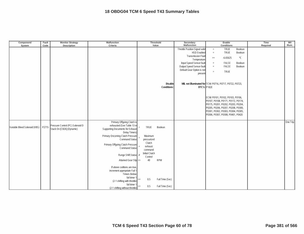
Component/ Fault Monitor Strategy Secondary MilSystem Code Description Malfunction Illum.
Malfunction Threshold Enable TimeCriteria Value Conditions Required
Throttle Position Signal valid = TRUE BooleanHSD Enabled = TRUE Boolean
Transmission Fluid Temperature >= -6.65625 ºC
Input Speed Sensor fault = FALSE BooleanOutput Speed Sensor fault = FALSE BooleanDefault Gear Option is not
present = TRUE
DisableConditions:
MIL not Illuminated forDTC's:
Variable Bleed Solenoid (VBS) P2715 Pressure Control (PC) Solenoid D Stuck On [CB26] (Dynamic)
Primary Offgoing Clutch isexhausted (See Table 13 in
Supporting Documents for Exhaust Delay Timers)
= TRUE Boolean
One Trip
Primary Oncoming Clutch Pressure Command Status = Maximum
pressurized
Primary Offgoing Clutch Pressure Command Status =
Clutch exhaust
command
Range Shift Status Initial Clutch Control
Attained Gear Slip <= 40 RPM
If above coditons are true,increment appropriate Fail 1
Timers Below:fail timer 1
(2-1 shifting with throttle) >= 0.5 Fail Time (Sec)
fail timer 1(2-1 shifting without throttle) >= 0.5 Fail Time (Sec)
TCM: P0716, P0717, P0722, P0723, P182E
ECM: P0101, P0102, P0103, P0106, P0107, P0108, P0171, P0172, P0174, P0175, P0201, P0202, P0203, P0204, P0205, P0206, P0207, P0208, P0300, P0301, P0302, P0303, P0304, P0305, P0306, P0307, P0308, P0401, P042E
18 OBDG04 TCM 6 Speed T43 Summary Tables
TCM 6 Speed T43 Section Page 60 of 78 Page 381 of 566

Component/ Fault Monitor Strategy Secondary MilSystem Code Description Malfunction Illum.
Malfunction Threshold Enable TimeCriteria Value Conditions Required
fail timer 1(2-3 shifting with throttle) >= 0.5 Fail Time (Sec)
fail timer 1(2-3 shifting without throttle) >= 0.5 Fail Time (Sec)
fail timer 1(2-4 shifting with throttle) >= 0.5 Fail Time (Sec)
fail timer 1(2-4 shifting without throttle) >= 0.5 Fail Time (Sec)
fail timer 1(6-4 shifting with throttle) >= 0.5 Fail Time (Sec)
fail timer 1(6-4 shifting without throttle) >= 0.5 Fail Time (Sec)
fail timer 1(6-5 shifting with throttle) >= 0.5 Fail Time (Sec)
fail timer 1(6-5 shifting without throttle) >= 0.5 Fail Time (Sec)
If Attained Gear Slip is Less thanAbove Cal Increment Fail Timers >=
Total Fail Time = (Fail 1 + Fail 2) See
Enable Timers for Fail Timer
1, and Reference Supporting Table 15 for Fail Timer 2
sec
If fail timer is greater than thresholdincrement corresponding gear fail
counter and total fail counter
2nd gear fail counter >= 3 Fail Counter From 2nd Gear
OR
6th gear fail counter >= 3 Fail Counter From 6th Gear
OR
total fail counter >= 5 Total Fail Counter
TUT Enable temperature >= -6.65625 ºCInput Speed Sensor fault = FALSE Boolean
18 OBDG04 TCM 6 Speed T43 Summary Tables
TCM 6 Speed T43 Section Page 61 of 78 Page 382 of 566
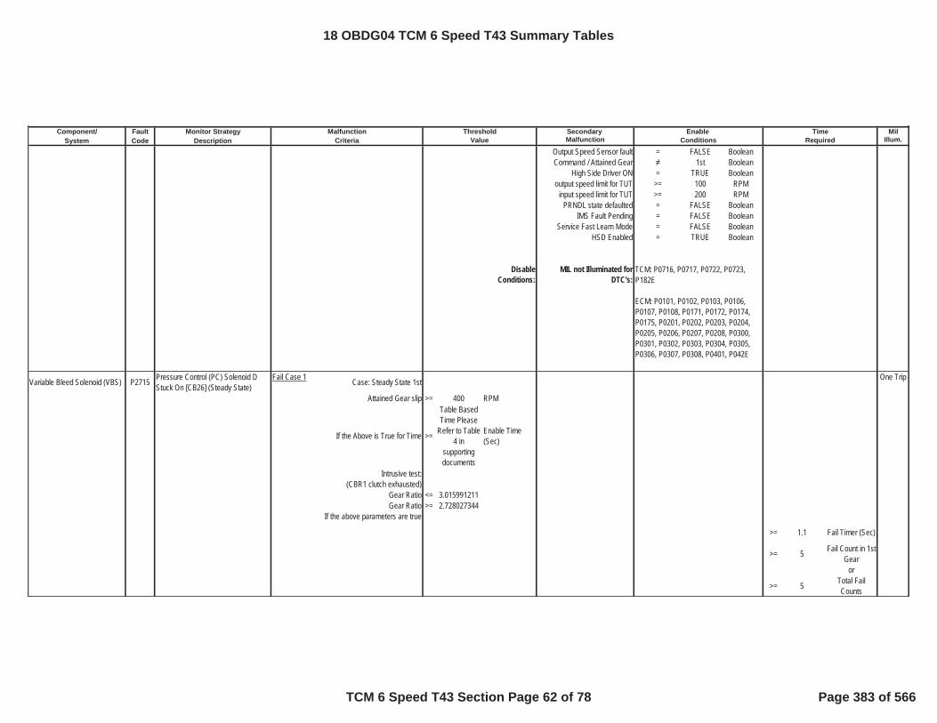
Component/ Fault Monitor Strategy Secondary MilSystem Code Description Malfunction Illum.
Malfunction Threshold Enable TimeCriteria Value Conditions Required
Output Speed Sensor fault = FALSE BooleanCommand / Attained Gear 1st Boolean
High Side Driver ON = TRUE Booleanoutput speed limit for TUT >= 100 RPM
input speed limit for TUT >= 200 RPMPRNDL state defaulted = FALSE Boolean
IMS Fault Pending = FALSE BooleanService Fast Learn Mode = FALSE Boolean
HSD Enabled = TRUE Boolean
DisableConditions:
MIL not Illuminated forDTC's:
Variable Bleed Solenoid (VBS) P2715 Pressure Control (PC) Solenoid D Stuck On [CB26] (Steady State)
Fail Case 1 Case: Steady State 1st One Trip
Attained Gear slip >= 400 RPM
If the Above is True for Time >=
Table Based Time Please
Refer to Table 4 in
supporting documents
Enable Time (Sec)
Intrusive test:(CBR1 clutch exhausted)
Gear Ratio <= 3.015991211Gear Ratio >= 2.728027344
If the above parameters are true
>= 1.1 Fail Timer (Sec)
>= 5 Fail Count in 1stGear
or
>= 5 Total Fail Counts
TCM: P0716, P0717, P0722, P0723, P182E
ECM: P0101, P0102, P0103, P0106, P0107, P0108, P0171, P0172, P0174, P0175, P0201, P0202, P0203, P0204, P0205, P0206, P0207, P0208, P0300, P0301, P0302, P0303, P0304, P0305, P0306, P0307, P0308, P0401, P042E
18 OBDG04 TCM 6 Speed T43 Summary Tables
TCM 6 Speed T43 Section Page 62 of 78 Page 383 of 566

Component/ Fault Monitor Strategy Secondary MilSystem Code Description Malfunction Illum.
Malfunction Threshold Enable TimeCriteria Value Conditions Required
Fail Case 2 Case: Steady State 3rd Gear
Max Delta Output Speed Hysteresis >=
Table Based value Please
Refer to Table 22 in
supporting documents
rpm/sec
Min Delta Output Speed Hysteresis >=
Table Based value Please
Refer to Table 23 in
supporting documents
rpm/sec
If the Above is True for Time >=
Table Based Time Please
Refer to Table 17 in
supporting documents
Sec
Intrusive test: (C35R clutch exhausted)
Gear Ratio <= 3.015991211Gear Ratio >= 2.728027344
If the above parameters are true
>= 1.1 Fail Timer (Sec)
>= 3 Fail Count in 3rd Gear
or
>= 5 Total Fail Counts
Fail Case 3 Case: Steady State 4rd Gear
Max Delta Output Speed Hysteresis >=
Table Based value Please
Refer to Table 22 in
supporting documents
rpm/sec
18 OBDG04 TCM 6 Speed T43 Summary Tables
TCM 6 Speed T43 Section Page 63 of 78 Page 384 of 566

Component/ Fault Monitor Strategy Secondary MilSystem Code Description Malfunction Illum.
Malfunction Threshold Enable TimeCriteria Value Conditions Required
Min Delta Output Speed Hysteresis >=
Table Based value Please
Refer to Table 23 in
supporting documents
rpm/sec
If the Above is True for Time >=
Table Based Time Please
Refer to Table 17 in
supporting documents
Sec
Intrusive test: (C1234 clutch exhausted)
Gear Ratio <= 0.779052734Gear Ratio >= 0.704956055
If the above parameters are true
>= 1.1 Fail Timer (Sec)
>= 3 Fail Count in 4thGear
or
>= 5 Total Fail Counts
Fail Case 4 Case: Steady State 5th Gear
Max Delta Output Speed Hysteresis >=
Table Based value Please
Refer to Table 22 in
supporting documents
rpm/sec
Min Delta Output Speed Hysteresis >=
Table Based value Please
Refer to Table 23 in
supporting documents
rpm/sec
18 OBDG04 TCM 6 Speed T43 Summary Tables
TCM 6 Speed T43 Section Page 64 of 78 Page 385 of 566

Component/ Fault Monitor Strategy Secondary MilSystem Code Description Malfunction Illum.
Malfunction Threshold Enable TimeCriteria Value Conditions Required
If the Above is True for Time >=
Table Based Time Please
Refer to Table 17 in
supporting documents
Sec
Intrusive test: (C35R clutch exhausted)
Gear Ratio <= 0.779052734Gear Ratio >= 0.704956055
If the above parameters are true
>= 1.1 Fail Timer (Sec)
>= 3 Fail Count in 5thGear
or
>= 5 Total Fail Counts
PRNDL State defaulted = FALSE Booleaninhibit RVT = FALSE Boolean
IMS fault pending indication = FALSE Booleanoutput speed >= 0 RPM
TPS validity flag = TRUE BooleanHSD Enabled = TRUE Boolean
Hydraulic_System_Pressurized = TRUE Boolean
A OR B(A) Output speed enable >= 36 Nm
(B) Accelerator Pedal enable >= 0.5004883 NmIgnition Voltage Lo >= 8.5996094 VoltsIgnition Voltage Hi <= 31.990234 VoltsEngine Speed Lo >= 400 RPMEngine Speed Hi <= 7500 RPM
Engine Speed is within theallowable limits for >= 5 Sec
if Attained Gear=1st FW Accelerator Pedal enable >= 5.0003052 Pct
if Attained Gear=1st FW Engine Torque Enable >= 20 Nm
if Attained Gear=1st FW Engine Torque Enable <= 8191.875 Nm
18 OBDG04 TCM 6 Speed T43 Summary Tables
TCM 6 Speed T43 Section Page 65 of 78 Page 386 of 566

Component/ Fault Monitor Strategy Secondary MilSystem Code Description Malfunction Illum.
Malfunction Threshold Enable TimeCriteria Value Conditions Required
Transmission Fluid Temperature >= -6.65625 ºC
Input Speed Sensor fault = FALSE BooleanOutput Speed Sensor fault = FALSE BooleanDefault Gear Option is not
present = TRUE
DisableConditions:
MIL not Illuminated forDTC's:
Variable Bleed Solenoid (VBS) P2720Pressure Control (PC) Solenoid D Control Circuit Low(CB26 VBS)
The HWIO reports a low voltage (ground short) error flag = TRUE Boolean >= 0.3 Fail Time (Sec)
One Trip
outof 0.375 Sample Time
(Sec)
P2770 Status is not =
Test Failed This Key
On or Fault Active
Ignition Voltage >= 8.5996094 VoltsIgnition Voltage <= 31.990234 Volts
Engine Speed >= 400 RPMEngine Speed <= 7500 RPM
Engine Speed is within the allowable limits for >= 5 Sec
DisableConditions:
MIL not Illuminated forDTC's:
TCM: None
ECM: None
TCM: P0716, P0717, P0722, P0723, P182E
ECM: P0101, P0102, P0103, P0106, P0107, P0108, P0171, P0172, P0174, P0175, P0201, P0202, P0203, P0204, P0205, P0206, P0207, P0208, P0300, P0301, P0302, P0303, P0304, P0305, P0306, P0307, P0308, P0401, P042E
18 OBDG04 TCM 6 Speed T43 Summary Tables
TCM 6 Speed T43 Section Page 66 of 78 Page 387 of 566

Component/ Fault Monitor Strategy Secondary MilSystem Code Description Malfunction Illum.
Malfunction Threshold Enable TimeCriteria Value Conditions Required
Variable Bleed Solenoid (VBS) P2721Pressure Control (PC) Solenoid D Control Circuit High(CB26 VBS)
The HWIO reports a high voltage (open or power short) error flag = TRUE Boolean >= 0.3 Fail Time (Sec)
One Trip
outof 0.375 Sample Time
(Sec)
P2721 Status is not =
Test Failed This Key
On or Fault Active
Ignition Voltage >= 8.5996094 VoltsIgnition Voltage <= 31.990234 Volts
Engine Speed >= 400 RPMEngine Speed <= 7500 RPM
Engine Speed is within the allowable limits for >= 5 Sec
DisableConditions:
MIL not Illuminated forDTC's:
Variable Bleed Solenoid (VBS) P2723 Pressure Control (PC) Solenoid E Stuck Off
Fail Case 1 Case: Steady State 1st Gear One Trip
Gear slip >= 400 RPM >=
Please See Table 5 For
Neutral Time Cal
Neutral Timer (Sec)
Intrusive test:commanded 2nd gear
If attained Gear 2nd for Time >=
Please refer toTable 3 in Supporting Documents
Shift Time (Sec)
If Above Conditions have been met, Increment 1st gear fail
counter>= 3 1st Gear Fail
Count
or
and C1234 fail counter >= 14 C1234 Clutch Fail Count
Fail Case 2 Case: Steady State 2nd Gear
TCM: None
ECM: None
18 OBDG04 TCM 6 Speed T43 Summary Tables
TCM 6 Speed T43 Section Page 67 of 78 Page 388 of 566

Component/ Fault Monitor Strategy Secondary MilSystem Code Description Malfunction Illum.
Malfunction Threshold Enable TimeCriteria Value Conditions Required
Gear slip >= 400 RPM >=
Please See Table 5 For
Neutral Time Cal
Neutral Timer (Sec)
Intrusive test:commanded 3rd gear
If attained Gear 3rd for Time >=
Please refer toTable 3 in Supporting Documents
Shift Time (Sec)
If Above Conditions have beenmet, Increment 2nd gear fail
counter>= 3 2nd Gear Fail
Count
or
and C1234 fail counter >= 14 C1234 Clutch Fail Count
Fail Case 3 Case: Steady State 3rd Gear
Gear slip >= 400 RPM >=
Please See Table 5 For
Neutral Time Cal
Neutral Timer (Sec)
Intrusive test:commanded 4th gear
If attained Gear 4th for time >=
Please refer toTable 3 in Supporting Documents
Shift Time (Sec)
If Above Conditions have beenmet, Increment 3rd gear fail
counter>= 3 3rd Gear Fail
Count
or
and C1234 fail counter >= 14 C1234 Clutch Fail Count
Fail Case 4 Case: Steady State 4th Gear
Gear slip >= 400 RPM >=
Please See Table 5 For
Neutral Time Cal
Neutral Timer (Sec)
Intrusive test:commanded 5th gear
18 OBDG04 TCM 6 Speed T43 Summary Tables
TCM 6 Speed T43 Section Page 68 of 78 Page 389 of 566

Component/ Fault Monitor Strategy Secondary MilSystem Code Description Malfunction Illum.
Malfunction Threshold Enable TimeCriteria Value Conditions Required
If attained Gear = 5th For Time >=
Please refer toTable 3 in Supporting Documents
Shift Time (Sec)
If Above Conditions have beenmet, Increment 4th gear fail
counter>= 3 4th Gear Fail
Count
or
and C1234 fail counter >= 14 C1234 Clutch Fail Count
PRNDL State defaulted = FALSE Booleaninhibit RVT = FALSE Boolean
IMS fault pending indication = FALSE BooleanTPS validity flag = TRUE Boolean
Hydraulic System Pressurized = TRUE Boolean
Minimum output speed for RVT >= 0 RPM
A OR B(A) Output speed enable >= 36 RPM
(B) Accelerator Pedal enable >= 0.5004883 PctCommon Enable Criteria
Ignition Voltage Lo >= 8.5996094 VoltsIgnition Voltage Hi <= 31.990234 VoltsEngine Speed Lo >= 400 RPMEngine Speed Hi <= 7500 RPM
Engine Speed is within theallowable limits for >= 5 Sec
Throttle Position Signal valid = TRUE BooleanHSD Enabled = TRUE Boolean
Transmission Fluid Temperature >= -6.65625 ºC
Input Speed Sensor fault = FALSE BooleanOutput Speed Sensor fault = FALSE BooleanDefault Gear Option is not
present = TRUE
18 OBDG04 TCM 6 Speed T43 Summary Tables
TCM 6 Speed T43 Section Page 69 of 78 Page 390 of 566

Component/ Fault Monitor Strategy Secondary MilSystem Code Description Malfunction Illum.
Malfunction Threshold Enable TimeCriteria Value Conditions Required
DisableConditions:
MIL not Illuminated forDTC's:
Variable Bleed Solenoid (VBS) P2724 Pressure Control (PC) Solenoid E Stuck On (Dynamic)
Primary Offgoing Clutch is exhausted (See Table 10 in
Supporting Documents for Exhaust Delay Timers)
= TRUE Boolean
One Trip
Primary Oncoming Clutch Pressure Command Status = Maximum
pressurized
Primary Offgoing Clutch PressureCommand Status =
Clutch exhaust
command
Range Shift Status Initial Clutch Control
Attained Gear Slip <= 40 RPMIf the above conditions are true
increment appropriate Fail 1 Timers Below:
fail timer 1(2-6 shifting with throttle) >= 0.5 sec
fail timer 1(2-6 shifting without throttle) >= 0.5 sec
fail timer 1(3-5 shifting with throttle) >= 0.5 sec
fail timer 1(3-5 shifting without throttle) >= 0.5 sec
fail timer 1(4-5 shifting with throttle) >= 0.5 sec
fail timer 1(4-5 shifting without throttle) >= 0.5 sec
fail timer 1(4-6 shifting with throttle) >= 0.5 sec
fail timer 1(4-6 shifting without throttle) >= 0.5 sec
TCM: P0716, P0717, P0722, P0723, P182E
ECM: P0101, P0102, P0103, P0106, P0107, P0108, P0171, P0172, P0174, P0175, P0201, P0202, P0203, P0204, P0205, P0206, P0207, P0208, P0300, P0301, P0302, P0303, P0304, P0305, P0306, P0307, P0308, P0401, P042E
18 OBDG04 TCM 6 Speed T43 Summary Tables
TCM 6 Speed T43 Section Page 70 of 78 Page 391 of 566

Component/ Fault Monitor Strategy Secondary MilSystem Code Description Malfunction Illum.
Malfunction Threshold Enable TimeCriteria Value Conditions Required
If Attained Gear Slip is Less than Above Cal Increment Fail Timers >=
Total Fail Time = (Fail 1 + Fail 2) See
Enable Timers for Fail Timer
1, and Reference Supporting Table 15 for Fail Timer 2
sec
If fail timer is greater than thresholdincrement corresponding gear fail
counter and total fail counter
2nd gear fail counter >= 3 Fail Counter From 2nd Gear
3rd gear fail counter >= 3 Fail Counter From 3rd Gear
4th gear fail counter >= 3 Fail Counter From 4th Gear
total fail counter >= 5 Total Fail Counter
TUT Enable temperature >= -6.65625 ºCInput Speed Sensor fault = FALSE Boolean
Output Speed Sensor fault = FALSE BooleanCommand / Attained Gear 1st Boolean
High Side Driver ON = TRUE Booleanoutput speed limit for TUT >= 100 RPM
input speed limit for TUT >= 200 RPMPRNDL state defaulted = FALSE Boolean
IMS Fault Pending = FALSE BooleanService Fast Learn Mode = FALSE Boolean
HSD Enabled = TRUE Boolean
18 OBDG04 TCM 6 Speed T43 Summary Tables
TCM 6 Speed T43 Section Page 71 of 78 Page 392 of 566

Component/ Fault Monitor Strategy Secondary MilSystem Code Description Malfunction Illum.
Malfunction Threshold Enable TimeCriteria Value Conditions Required
DisableConditions:
MIL not Illuminated forDTC's:
Variable Bleed Solenoid (VBS) P2724 Pressure Control (PC) Solenoid E Stuck On (Steady State)
Fail Case 1 Case: 5th Gear One Trip
Max Delta Output Speed Hysteresis >=
Table Based value Please
Refer to Table 22 in
supporting documents
rpm/sec
Min Delta Output Speed Hysteresis >=
Table Based value Please
Refer to Table 23 in
supporting documents
rpm/sec
If the Above is True for Time >=
Table Based Time Please
Refer to Table 17 in
supporting documents
Sec
Intrusive test:(C35R clutch exhausted)
Gear Ratio <= 1.484985352Gear Ratio >= 1.343017578
If the above parameters are true
>= 1.1 Fail Timer (Sec)
>= 3 Fail Count in 5thGearOR
>= 3 Total Fail Counts
TCM: P0716, P0717, P0722, P0723, P182E
ECM: P0101, P0102, P0103, P0106, P0107, P0108, P0171, P0172, P0174, P0175, P0201, P0202, P0203, P0204, P0205, P0206, P0207, P0208, P0300, P0301, P0302, P0303, P0304, P0305, P0306, P0307, P0308, P0401, P042E
18 OBDG04 TCM 6 Speed T43 Summary Tables
TCM 6 Speed T43 Section Page 72 of 78 Page 393 of 566
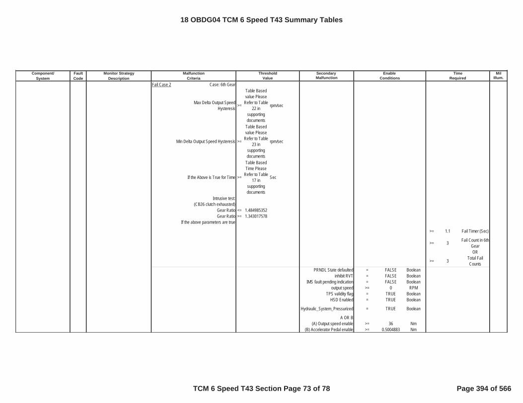
Component/ Fault Monitor Strategy Secondary MilSystem Code Description Malfunction Illum.
Malfunction Threshold Enable TimeCriteria Value Conditions Required
Fail Case 2 Case: 6th Gear
Max Delta Output Speed Hysteresis >=
Table Based value Please
Refer to Table 22 in
supporting documents
rpm/sec
Min Delta Output Speed Hysteresis >=
Table Based value Please
Refer to Table 23 in
supporting documents
rpm/sec
If the Above is True for Time >=
Table Based Time Please
Refer to Table 17 in
supporting documents
Sec
Intrusive test:(CB26 clutch exhausted)
Gear Ratio <= 1.484985352Gear Ratio >= 1.343017578
If the above parameters are true
>= 1.1 Fail Timer (Sec)
>= 3 Fail Count in 6thGearOR
>= 3 Total Fail Counts
PRNDL State defaulted = FALSE Booleaninhibit RVT = FALSE Boolean
IMS fault pending indication = FALSE Booleanoutput speed >= 0 RPM
TPS validity flag = TRUE BooleanHSD Enabled = TRUE Boolean
Hydraulic_System_Pressurized = TRUE Boolean
A OR B(A) Output speed enable >= 36 Nm
(B) Accelerator Pedal enable >= 0.5004883 Nm
18 OBDG04 TCM 6 Speed T43 Summary Tables
TCM 6 Speed T43 Section Page 73 of 78 Page 394 of 566

Component/ Fault Monitor Strategy Secondary MilSystem Code Description Malfunction Illum.
Malfunction Threshold Enable TimeCriteria Value Conditions Required
Ignition Voltage Lo >= 8.5996094 VoltsIgnition Voltage Hi <= 31.990234 VoltsEngine Speed Lo >= 400 RPMEngine Speed Hi <= 7500 RPM
Engine Speed is within the allowable limits for >= 5 Sec
if Attained Gear=1st FW Accelerator Pedal enable >= 5.0003052 Pct
if Attained Gear=1st FW Engine Torque Enable >= 20 Nm
if Attained Gear=1st FWEngine Torque Enable <= 8191.875 Nm
Transmission FluidTemperature >= -6.65625 ºC
Input Speed Sensor fault = FALSE BooleanOutput Speed Sensor fault = FALSE BooleanDefault Gear Option is not
present = TRUE
DisableConditions:
MIL not Illuminated forDTC's:
Variable Bleed Solenoid (VBS) P2729Pressure Control (PC) Solenoid E Control Circuit Low(C1234 VBS)
The HWIO reports a low voltage(ground short) error flag = TRUE Boolean >= 0.3 Fail Time (Sec)
One Trip
outof 0.375 Sample Time
(Sec)
P2729 Status is not =
Test FailedThis Key
On or Fault Active
Ignition Voltage >= 8.5996094 Volt
TCM: P0716, P0717, P0722, P0723, P182E
ECM: P0101, P0102, P0103, P0106, P0107, P0108, P0171, P0172, P0174, P0175, P0201, P0202, P0203, P0204, P0205, P0206, P0207, P0208, P0300, P0301, P0302, P0303, P0304, P0305, P0306, P0307, P0308, P0401, P042E
18 OBDG04 TCM 6 Speed T43 Summary Tables
TCM 6 Speed T43 Section Page 74 of 78 Page 395 of 566

Component/ Fault Monitor Strategy Secondary MilSystem Code Description Malfunction Illum.
Malfunction Threshold Enable TimeCriteria Value Conditions Required
Ignition Voltage <= 31.990234 VoltEngine Speed >= 400 RPMEngine Speed <= 7500 RPM
Engine Speed is within the allowable limits for >= 5 Sec
DisableConditions:
MIL not Illuminated forDTC's:
Variable Bleed Solenoid (VBS) P2730Pressure Control (PC) Solenoid E Control Circuit High(C1234 VBS)
The HWIO reports a high voltage(open or power short) error flag = TRUE Boolean >= 0.3 Fail Time (Sec)
One Trip
outof 0.375 Sample Time
(Sec)
P2730 Status is not =
Test Failed This Key
On or Fault Active
Ignition Voltage >= 8.5996094 VoltIgnition Voltage <= 31.990234 Volt
Engine Speed >= 400 RPMEngine Speed <= 7500 RPM
Engine Speed is within the allowable limits for >= 5 Sec
DisableConditions:
MIL not Illuminated forDTC's:
Variable Bleed Solenoid (VBS) P2763 Torque Converter Clutch Pressure High
The HWIO reports a lowpressure/high voltage (open or
power short) error flag= TRUE Boolean >= 4.4 Fail Time (Sec)
TwoTrips
outof 5 Sample Time
(Sec)
TCM: None
ECM: None
TCM: None
ECM: None
18 OBDG04 TCM 6 Speed T43 Summary Tables
TCM 6 Speed T43 Section Page 75 of 78 Page 396 of 566

Component/ Fault Monitor Strategy Secondary MilSystem Code Description Malfunction Illum.
Malfunction Threshold Enable TimeCriteria Value Conditions Required
P2763 Status is not =
Test FailedThis Key
On or Fault Active
Ignition Voltage >= 8.5996094 VoltIgnition Voltage <= 31.990234 Volt
Engine Speed >= 400 RPMEngine Speed <= 7500 RPM
Engine Speed is within the allowable limits for >= 5 Sec
High Side Driver Enabled = TRUE Boolean
DisableConditions:
MIL not Illuminated forDTC's:
Variable Bleed Solenoid (VBS) P2764 Torque Converter Clutch Pressure Control Solenoid Control Circuit Low
The HWIO reports a high pressure/low voltage (ground
short) error flag= TRUE Boolean >= 4.4 Fail Time (Sec)
One Trip
outof 5 Sample Time
(Sec)
P2764 Status is not =
Test FailedThis Key
On or Fault Active
Ignition Voltage >= 8.5996094 VoltIgnition Voltage <= 31.990234 Volt
Engine Speed >= 400 RPMEngine Speed <= 7500 RPM
Engine Speed is within the allowable limits for >= 5 Sec
High Side Driver Enabled = TRUE Boolean
DisableConditions:
MIL not Illuminated forDTC's:
TCM: P0658, P0659
ECM: None
TCM: P0658, P0659
ECM: None
18 OBDG04 TCM 6 Speed T43 Summary Tables
TCM 6 Speed T43 Section Page 76 of 78 Page 397 of 566

Component/ Fault Monitor Strategy Secondary MilSystem Code Description Malfunction Illum.
Malfunction Threshold Enable TimeCriteria Value Conditions Required
Communication U0073 Controller Area Network Bus Communication Error
CAN Hardware Circuitry Detects a Low Voltage Error = TRUE Boolean >= 62 Fail counts (
10 seconds)One Trip
Delay timer >= 0.1125 sec Out of 70 Sample Counts
( 11 seconds)Stabilization delay >= 3 sec
Ignition Voltage >= 8.5996094 VoltIgnition Voltage <= 31.990234 Volt
Power Mode = Run
DisableConditions:
MIL not Illuminated forDTC's:
Communication U0100 Lost Communications with ECM (Engine Control Module)
CAN messages from ECM are notreceived by the TCM = TRUE Boolean >= 12 sec One Trip
Stabilization delay >= 3 secIgnition Voltage >= 8.5996094 VoltIgnition Voltage <= 31.990234 Volt
Power Mode = Run
DisableConditions:
MIL not Illuminated forDTC's:
Transmission Control Module (TCM) C1251 The lateral accleration signal is stuck
at a high magnitude in range absolute value (lateral accleration) >= 0.529999971 g's absolute value (lateral accleration) for stablity >= 0.53 g's >= 75 Sec Special
No MIL
absolute value (lateral accleration) <= 3.849999905 g's absolute value (lateral accleration) for stablity <= 3.8499999 g's
stability time >= 30 SecDiagnostic shifting override
command = FALSE Boolean
Attained Gear State = 1st through 8th
Attained Gear Slip <= 100 RPM
Transmission Type =
Clutch to Clutch
Transmission
High Side Drivers enabled = TRUE Boolean
TCM: None
ECM: None
TCM: U0073
ECM: None
18 OBDG04 TCM 6 Speed T43 Summary Tables
TCM 6 Speed T43 Section Page 77 of 78 Page 398 of 566
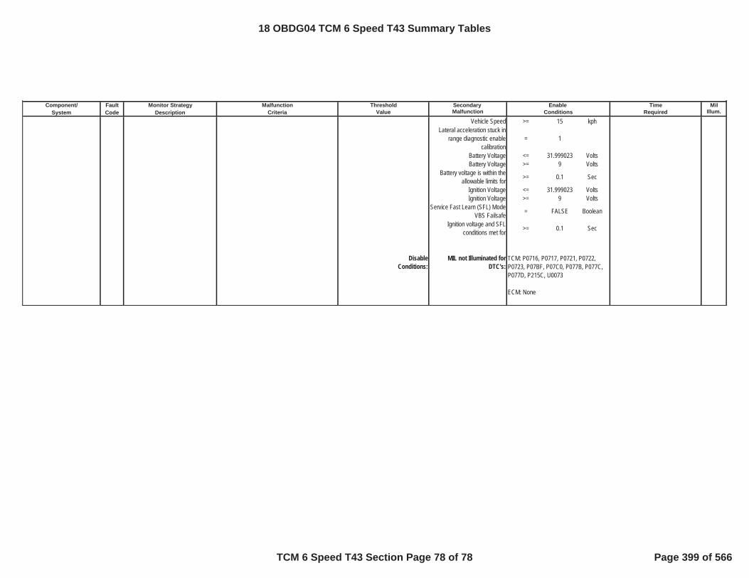
Component/ Fault Monitor Strategy Secondary MilSystem Code Description Malfunction Illum.
Malfunction Threshold Enable TimeCriteria Value Conditions Required
Vehicle Speed >= 15 kphLateral acceleration stuck in
range diagnostic enable calibration
= 1
Battery Voltage <= 31.999023 VoltsBattery Voltage >= 9 Volts
Battery voltage is within the allowable limits for >= 0.1 Sec
Ignition Voltage <= 31.999023 VoltsIgnition Voltage >= 9 Volts
Service Fast Learn (SFL) Mode VBS Failsafe = FALSE Boolean
Ignition voltage and SFL conditions met for >= 0.1 Sec
DisableConditions:
MIL not Illuminated forDTC's:
TCM: P0716, P0717, P0721, P0722, P0723, P07BF, P07C0, P077B, P077C, P077D, P215C, U0073
ECM: None
18 OBDG04 TCM 6 Speed T43 Summary Tables
TCM 6 Speed T43 Section Page 78 of 78 Page 399 of 566

Table 1KaCANG_RxDeviceIndx Axis CeCANG_e_RcvMsg_0BE_BusA CeCANG_e_RcvMsg_0C1_BusA CeCANG_e_RcvMsg_0C5_BusA CeCANG_e_RcvMsg_0C9_BusA frameKaCANG_RxDeviceIndx Curve CeCANR_e_BusA_ECM CeCANR_e_BusA_ABS CeCANR_e_BusA_ABS CeCANR_e_BusA_ECM enable or invalid
Axis CeCANG_e_RcvMsg_0D0_BusA CeCANG_e_RcvMsg_0F1_BusA CeCANG_e_RcvMsg_191_BusA CeCANG_e_RcvMsg_1A1_BusA frameCurve CeCANR_e_BusA_ABS CeCANR_e_BusA_BCM CeCANR_e_BusA_ECM CeCANR_e_BusA_ECM enable or invalid
Axis CeCANG_e_RcvMsg_1CF_BusA CeCANG_e_RcvMsg_1E1_BusA CeCANG_e_RcvMsg_1E9_BusA CeCANG_e_RcvMsg_1F3_BusA frameCurve CeCANR_e_InvalidRxDevice CeCANR_e_BusA_BCM CeCANR_e_BusA_ABS CeCANR_e_BusA_BCM enable or invalid
Axis CeCANG_e_RcvMsg_1F9_BusA CeCANG_e_RcvMsg_1FC_BusA CeCANG_e_RcvMsg_287_BusA CeCANG_e_RcvMsg_2C3_BusA frameCurve CeCANR_e_BusA_PTO CeCANR_e_InvalidRxDevice CeCANR_e_BusA_ECM CeCANR_e_BusA_ECM enable or invalid
Axis CeCANG_e_RcvMsg_2D1_BusA CeCANG_e_RcvMsg_2F9_BusA CeCANG_e_RcvMsg_3B9_BusA CeCANG_e_RcvMsg_3D1_BusA frameCurve CeCANR_e_InvalidRxDevice CeCANR_e_BusA_ABS CeCANR_e_BusA_ECM CeCANR_e_BusA_ECM enable or invalid
Axis CeCANG_e_RcvMsg_3E9_BusA CeCANG_e_RcvMsg_3F1_BusA CeCANG_e_RcvMsg_3F9_BusA CeCANG_e_RcvMsg_4C1_BusA frameCurve CeCANR_e_BusA_ECM CeCANR_e_BusA_BCM CeCANR_e_BusA_ECM CeCANR_e_BusA_ECM enable or invalid
Axis CeCANG_e_RcvMsg_4F1_BusA frameCurve CeCANR_e_BusA_ECM enable or invalid
DIAGNOSTIC SUPPORTING TABLE--TCM 6 Speed T87A
18 OBDG04
TCM 6 Speed T87A Supporting Table Page 1 of 1 Page 400 of 566

Initial Supporting table - 10 speed transmission clutch definition and gear state to clutch map
Description: indicates clutch definition and gear state verses applied and released clutches for 10 speed transmission
Value Units: applied or releasedX Unit: clutchY Units: gear index Y axis, actual gear column 1
y/x 1 2 3 4 5 6 7 81 C1 = C123456R C2 = C1289-10R C3 = C234579-10 C4 = C234678-10R C5 = C1356789 C6 = C456789-10R C7 = OWC122 1st gear braking applied applied released released applied released applied3 1st gear free wheel applied applied released released applied released released4 2nd gear braking applied applied applied applied released released applied5 2nd gear free wheel applied applied applied applied released released released6 3rd gear applied released applied applied applied released released7 4th gear applied released applied applied released applied released8 5th gear applied released applied released applied applied released9 6th gear applied released released released applied applied released10 7th gear released released applied applied applied applied released11 8th gear released applied released applied applied applied released12 9th gear released applied applied released applied applied released13 10th gear released applied applied applied released applied released14 reverse gear applied applied released applied released released released
18 OBDG04 TCM 9 Speed T87A Supporting Tables
TCM 9 Speed T87A Supporting Tables Page 1 of 161 Page 401 of 566

Initial Supporting table - 9 speed transmission clutch definition and gear state to clutch map
Description: indicates clutch definition and gear state verses applied and released clutches for 9 speed transmission
Value Units: applied or releasedX Unit: clutchY Units: gear index Y axis, actual gear column 1
y/x 1 2 3 4 5 6 7 81 C1 = CB123456 C2 = C6789 C3 = CB1R C4 = CB29 C5 = CB38 C6 = C4 C7 = C57R2 1st gear braking applied released applied released released released released3 1st gear free wheel applied released released released released released released4 2nd gear applied released released applied released released released5 3rd gear applied released released released applied released released6 4th gear applied released released released released applied released7 5th gear applied released released released released released applied8 6th gear applied applied released released released released released9 7th gear released applied released released released released applied10 8th gear released applied released released applied released released11 9th gear released applied released applied released released released12 reverse gear released released applied released released released applied
18 OBDG04 TCM 9 Speed T87A Supporting Tables
TCM 9 Speed T87A Supporting Tables Page 2 of 161 Page 402 of 566

Initial Supporting table - engine speed time for transmission hydraulic pressure available
Description: time needed for engine speed to trigger "transmission hydraulic pressure available"
Value Units: secondsX Unit: °C
y/x -40.00 -30.00 -20.00 0.00 40.001 0.300 0.300 0.275 0.200 0.100
18 OBDG04 TCM 9 Speed T87A Supporting Tables
TCM 9 Speed T87A Supporting Tables Page 3 of 161 Page 403 of 566

Initial Supporting table - engine speed time for transmission hydraulic pressure available
Description: time needed for engine speed to trigger "transmission hydraulic pressure available"
Value Units: secondsX Unit: °C
y/x -40.00 -30.00 -20.00 0.00 40.001 0.300 0.300 0.275 0.200 0.100
18 OBDG04 TCM 9 Speed T87A Supporting Tables
TCM 9 Speed T87A Supporting Tables Page 4 of 161 Page 404 of 566

Initial Supporting table - engine speed time for transmission hydraulic pressure available
Description: time needed for engine speed to trigger "transmission hydraulic pressure available"
Value Units: secondsX Unit: transmission fluid temperature °C
y/x -40.00 -30.00 -20.00 0.00 40.001 0.300 0.300 0.275 0.200 0.100
18 OBDG04 TCM 9 Speed T87A Supporting Tables
TCM 9 Speed T87A Supporting Tables Page 5 of 161 Page 405 of 566

Initial Supporting table - engine speed time for transmission hydraulic pressure available
Description: time needed for engine speed to trigger "transmission hydraulic pressure available"
Value Units: secondsX Unit: °C
y/x -40.00 -30.00 -20.00 0.00 40.001 0.300 0.300 0.275 0.200 0.100
18 OBDG04 TCM 9 Speed T87A Supporting Tables
TCM 9 Speed T87A Supporting Tables Page 6 of 161 Page 406 of 566

Initial Supporting table - KtPSDR_t_ModeVlvA_EngOff_Lim
Description: used for both engine off mode valve A stability delay time required to enable fail time update and fail time threshold
Value Units: secondsX Unit: transmission fluid temperature, degrees CelsiusY Units: unitless
y/x -40 -20 0 20 1301 0.650 0.650 0.650 0.650 0.650
18 OBDG04 TCM 9 Speed T87A Supporting Tables
TCM 9 Speed T87A Supporting Tables Page 7 of 161 Page 407 of 566

Initial Supporting table - KtPSDR_t_ModeVlvA_TurbDlyLim
Description: mode valve A transtion delay
Value Units: secondsX Unit: transmission fluid temperature, degrees CelsiusY Units: unitless
y/x -40 -20 0 20 1301 1.500 1.000 0.750 0.500 0.300
18 OBDG04 TCM 9 Speed T87A Supporting Tables
TCM 9 Speed T87A Supporting Tables Page 8 of 161 Page 408 of 566

Initial Supporting table - KtPSDR_t_ModeVlvB_EngOff_Lim
Description: used for both engine off mode valve B stability delay time required to enable fail time update and fail time threshold
Value Units: secondsX Unit: transmission fluid temperature, degrees Celsius
y/x -40 -20 0 20 1301 0.250 0.250 0.250 0.250 0.250
18 OBDG04 TCM 9 Speed T87A Supporting Tables
TCM 9 Speed T87A Supporting Tables Page 9 of 161 Page 409 of 566

Initial Supporting table - KtPSDR_t_ParkServo_EngOff_Lim
Description: P187E time engine must be not running to enable fail time update
Value Units: secondsX Unit: transmission fluid temperature, degrees CelsiusY Units: unitless
y/x -40.00 -20.00 0.00 20.00 130.001 0.250 0.250 0.250 0.250 0.250
18 OBDG04 TCM 9 Speed T87A Supporting Tables
TCM 9 Speed T87A Supporting Tables Page 10 of 161 Page 410 of 566

Initial Supporting table - KtPSDR_t_ParkStatDlyLim
Description: fail delay time
Value Units: secondsX Unit: transmission fluid temperature, degrees CelsiusY Units: unitless
y/x -40.00 -20.00 0.00 20.00 130.001 0.500 0.500 0.500 0.500 0.500
18 OBDG04 TCM 9 Speed T87A Supporting Tables
TCM 9 Speed T87A Supporting Tables Page 11 of 161 Page 411 of 566

Initial Supporting table - KtPSDR_t_ParkVlvStkOff_DlyLim
Description: P187E Transmission Park Valve Stuck Off fail enable delay time
Value Units: secondsX Unit: transmission fluid temperature, degrees CelsiusY Units: unitless
y/x -40.00 -20.00 0.00 20.00 130.001 1.250 1.250 1.250 1.250 1.250
18 OBDG04 TCM 9 Speed T87A Supporting Tables
TCM 9 Speed T87A Supporting Tables Page 12 of 161 Page 412 of 566

Initial Supporting table - KtPSDR_t_ParkVlvStkOn_DlyLim
Description: P187D Transmission Park Valve Stuck On fail enable delay time
Value Units: secondsX Unit: transmission fluid temperature, degrees CelsiusY Units: unitless
y/x -40.00 -20.00 0.00 20.00 130.001.00 1.250 1.250 1.250 1.250 1.250
18 OBDG04 TCM 9 Speed T87A Supporting Tables
TCM 9 Speed T87A Supporting Tables Page 13 of 161 Page 413 of 566
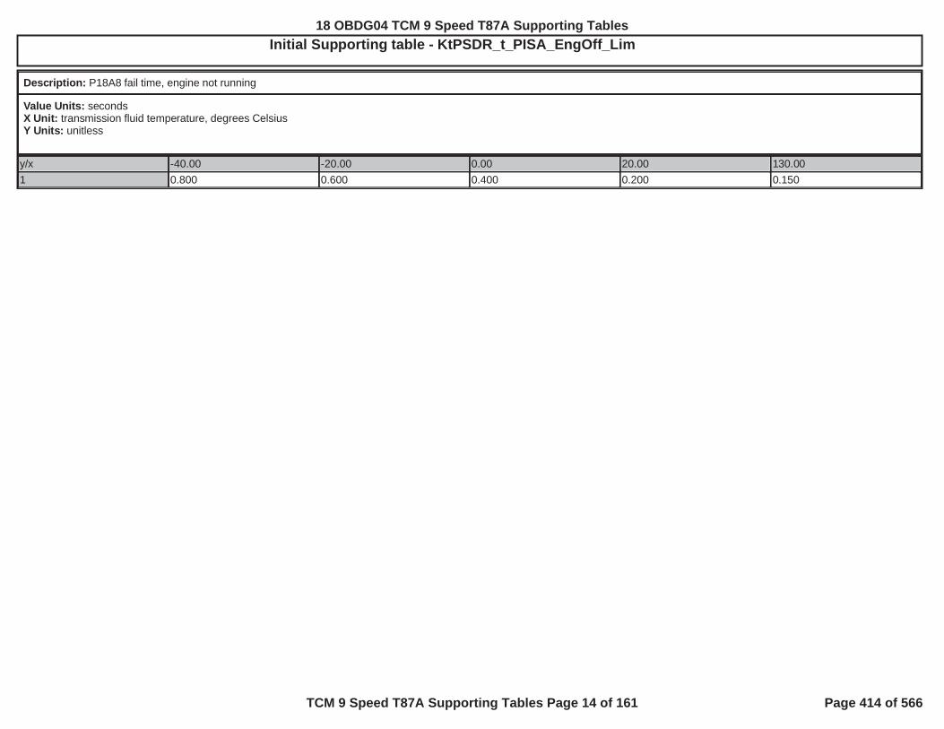
Initial Supporting table - KtPSDR_t_PISA_EngOff_Lim
Description: P18A8 fail time, engine not running
Value Units: secondsX Unit: transmission fluid temperature, degrees CelsiusY Units: unitless
y/x -40.00 -20.00 0.00 20.00 130.001 0.800 0.600 0.400 0.200 0.150
18 OBDG04 TCM 9 Speed T87A Supporting Tables
TCM 9 Speed T87A Supporting Tables Page 14 of 161 Page 414 of 566
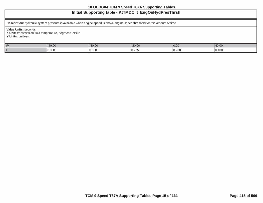
Initial Supporting table - KtTMDC_t_EngOnHydPresThrsh
Description: hydraulic system pressure is available when engine speed is above engine speed threshold for this amount of time
Value Units: secondsX Unit: transmission fluid temperature, degrees CelsiusY Units: unitless
y/x -40.00 -30.00 -20.00 0.00 40.001 0.300 0.300 0.275 0.200 0.100
18 OBDG04 TCM 9 Speed T87A Supporting Tables
TCM 9 Speed T87A Supporting Tables Page 15 of 161 Page 415 of 566

Initial Supporting table - MaxSpdGr1
Description: MaxSpdGr1
Value Units: KphX Unit: Cmnd GearY Units: Kph
y/x 11 71
18 OBDG04 TCM 9 Speed T87A Supporting Tables
TCM 9 Speed T87A Supporting Tables Page 16 of 161 Page 416 of 566

Initial Supporting table - MaxSpdGr1
Description: MaxSpdGr1
Value Units: KPHX Unit: command gearY Units: unitless
y/x 11 71
18 OBDG04 TCM 9 Speed T87A Supporting Tables
TCM 9 Speed T87A Supporting Tables Page 17 of 161 Page 417 of 566

Initial Supporting table - MaxSpdGr10
Description: MaxSpdGr10
Value Units: KphX Unit: Cmnd GearY Units: Kph
y/x 11 540
18 OBDG04 TCM 9 Speed T87A Supporting Tables
TCM 9 Speed T87A Supporting Tables Page 18 of 161 Page 418 of 566

Initial Supporting table - MaxSpdGr10
Description: MaxSpdGr10
Value Units: KphX Unit: Cmnd GearY Units: Kph
y/x 11 540
18 OBDG04 TCM 9 Speed T87A Supporting Tables
TCM 9 Speed T87A Supporting Tables Page 19 of 161 Page 419 of 566

Initial Supporting table - MaxSpdGr2
Description: MaxSpdGr2
Value Units: KphX Unit: Cmnd GearY Units: Kph
y/x 11 101
18 OBDG04 TCM 9 Speed T87A Supporting Tables
TCM 9 Speed T87A Supporting Tables Page 20 of 161 Page 420 of 566

Initial Supporting table - MaxSpdGr2
Description: MaxSpdGr2
Value Units: KphX Unit: Cmnd GearY Units: Kph
y/x 11 101
18 OBDG04 TCM 9 Speed T87A Supporting Tables
TCM 9 Speed T87A Supporting Tables Page 21 of 161 Page 421 of 566

Initial Supporting table - MaxSpdGr3
Description: MaxSpdGr3
Value Units: KphX Unit: Cmnd GearY Units: Kph
y/x 11 111
18 OBDG04 TCM 9 Speed T87A Supporting Tables
TCM 9 Speed T87A Supporting Tables Page 22 of 161 Page 422 of 566
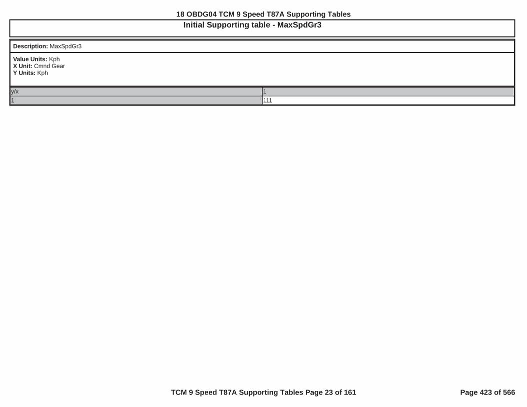
Initial Supporting table - MaxSpdGr3
Description: MaxSpdGr3
Value Units: KphX Unit: Cmnd GearY Units: Kph
y/x 11 111
18 OBDG04 TCM 9 Speed T87A Supporting Tables
TCM 9 Speed T87A Supporting Tables Page 23 of 161 Page 423 of 566

Initial Supporting table - MaxSpdGr4
Description: MaxSpdGr4
Value Units: KphX Unit: Cmnd GearY Units: Kph
y/x 11 136
18 OBDG04 TCM 9 Speed T87A Supporting Tables
TCM 9 Speed T87A Supporting Tables Page 24 of 161 Page 424 of 566

Initial Supporting table - MaxSpdGr4
Description: MaxSpdGr4
Value Units: KphX Unit: Cmnd GearY Units: Kph
y/x 11 136
18 OBDG04 TCM 9 Speed T87A Supporting Tables
TCM 9 Speed T87A Supporting Tables Page 25 of 161 Page 425 of 566

Initial Supporting table - MaxSpdGr5
Description: MaxSpdGr5
Value Units: KphX Unit: Cmnd GearY Units: Kph
y/x 11 173
18 OBDG04 TCM 9 Speed T87A Supporting Tables
TCM 9 Speed T87A Supporting Tables Page 26 of 161 Page 426 of 566

Initial Supporting table - MaxSpdGr5
Description: MaxSpdGr5
Value Units: KphX Unit: Cmnd GearY Units: Kph
y/x 11 173
18 OBDG04 TCM 9 Speed T87A Supporting Tables
TCM 9 Speed T87A Supporting Tables Page 27 of 161 Page 427 of 566

Initial Supporting table - MaxSpdGr6
Description: MaxSpdGr6
Value Units: KphX Unit: Cmnd GearY Units: Kph
y/x 11 230
18 OBDG04 TCM 9 Speed T87A Supporting Tables
TCM 9 Speed T87A Supporting Tables Page 28 of 161 Page 428 of 566

Initial Supporting table - MaxSpdGr6
Description: MaxSpdGr6
Value Units: KphX Unit: Cmnd GearY Units: Kph
y/x 11 230
18 OBDG04 TCM 9 Speed T87A Supporting Tables
TCM 9 Speed T87A Supporting Tables Page 29 of 161 Page 429 of 566

Initial Supporting table - MaxSpdGr7
Description: MaxSpdGr7
Value Units: KphX Unit: Cmnd GearY Units: Kph
y/x 11 333
18 OBDG04 TCM 9 Speed T87A Supporting Tables
TCM 9 Speed T87A Supporting Tables Page 30 of 161 Page 430 of 566

Initial Supporting table - MaxSpdGr7
Description: MaxSpdGr7
Value Units: KphX Unit: Cmnd GearY Units: Kph
y/x 11 333
18 OBDG04 TCM 9 Speed T87A Supporting Tables
TCM 9 Speed T87A Supporting Tables Page 31 of 161 Page 431 of 566

Initial Supporting table - MaxSpdGr8
Description: MaxSpdGr8
Value Units: KphX Unit: Cmnd GearY Units: Kph
y/x 11 446
18 OBDG04 TCM 9 Speed T87A Supporting Tables
TCM 9 Speed T87A Supporting Tables Page 32 of 161 Page 432 of 566

Initial Supporting table - MaxSpdGr8
Description: MaxSpdGr8
Value Units: KphX Unit: Cmnd GearY Units: Kph
y/x 11 446
18 OBDG04 TCM 9 Speed T87A Supporting Tables
TCM 9 Speed T87A Supporting Tables Page 33 of 161 Page 433 of 566

Initial Supporting table - MaxSpdGr9
Description: MaxSpdGr9
Value Units: KphX Unit: Cmnd GearY Units: Kph
y/x 11 540
18 OBDG04 TCM 9 Speed T87A Supporting Tables
TCM 9 Speed T87A Supporting Tables Page 34 of 161 Page 434 of 566

Initial Supporting table - MaxSpdGr9
Description: MaxSpdGr9
Value Units: KphX Unit: Cmnd GearY Units: Kph
y/x 11 540
18 OBDG04 TCM 9 Speed T87A Supporting Tables
TCM 9 Speed T87A Supporting Tables Page 35 of 161 Page 435 of 566
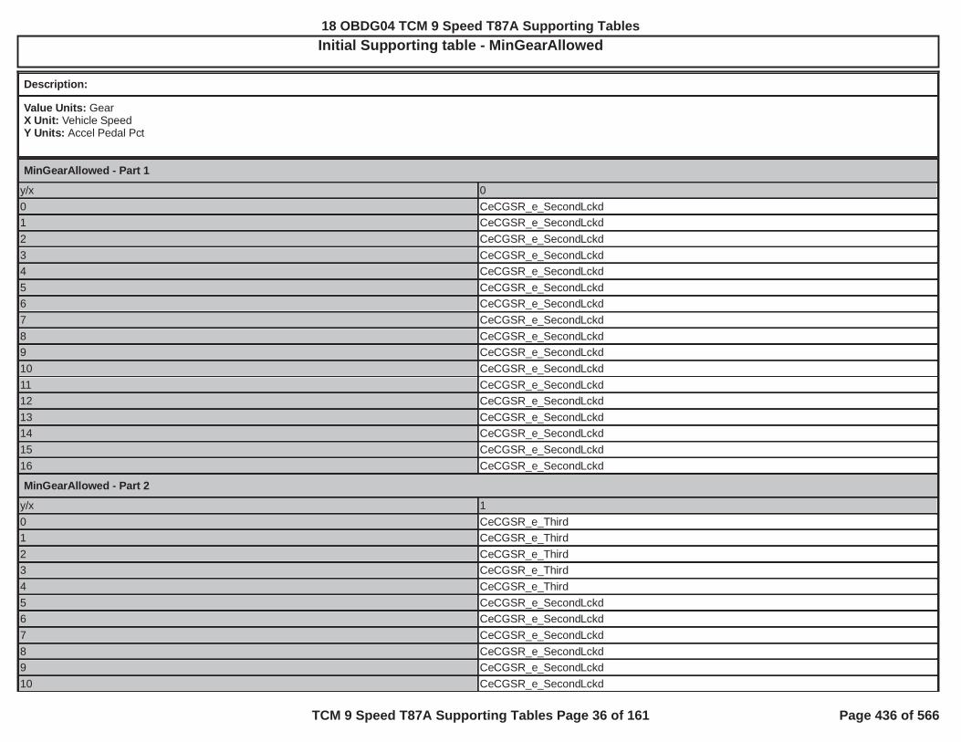
Initial Supporting table - MinGearAllowed
Description:
Value Units: GearX Unit: Vehicle SpeedY Units: Accel Pedal Pct
MinGearAllowed - Part 1
y/x 00 CeCGSR_e_SecondLckd1 CeCGSR_e_SecondLckd2 CeCGSR_e_SecondLckd3 CeCGSR_e_SecondLckd4 CeCGSR_e_SecondLckd5 CeCGSR_e_SecondLckd6 CeCGSR_e_SecondLckd7 CeCGSR_e_SecondLckd8 CeCGSR_e_SecondLckd9 CeCGSR_e_SecondLckd10 CeCGSR_e_SecondLckd11 CeCGSR_e_SecondLckd12 CeCGSR_e_SecondLckd13 CeCGSR_e_SecondLckd14 CeCGSR_e_SecondLckd15 CeCGSR_e_SecondLckd16 CeCGSR_e_SecondLckd
MinGearAllowed - Part 2
y/x 10 CeCGSR_e_Third1 CeCGSR_e_Third2 CeCGSR_e_Third3 CeCGSR_e_Third4 CeCGSR_e_Third5 CeCGSR_e_SecondLckd6 CeCGSR_e_SecondLckd7 CeCGSR_e_SecondLckd8 CeCGSR_e_SecondLckd9 CeCGSR_e_SecondLckd10 CeCGSR_e_SecondLckd
18 OBDG04 TCM 9 Speed T87A Supporting Tables
TCM 9 Speed T87A Supporting Tables Page 36 of 161 Page 436 of 566

Initial Supporting table - MinGearAllowed
11 CeCGSR_e_SecondLckd12 CeCGSR_e_SecondLckd13 CeCGSR_e_SecondLckd14 CeCGSR_e_SecondLckd15 CeCGSR_e_SecondLckd16 CeCGSR_e_SecondLckd
MinGearAllowed - Part 3
y/x 20 CeCGSR_e_Fourth1 CeCGSR_e_Fourth2 CeCGSR_e_Fourth3 CeCGSR_e_Fourth4 CeCGSR_e_Fourth5 CeCGSR_e_Fourth6 CeCGSR_e_SecondLckd7 CeCGSR_e_SecondLckd8 CeCGSR_e_SecondLckd9 CeCGSR_e_SecondLckd10 CeCGSR_e_SecondLckd11 CeCGSR_e_SecondLckd12 CeCGSR_e_SecondLckd13 CeCGSR_e_SecondLckd14 CeCGSR_e_SecondLckd15 CeCGSR_e_SecondLckd16 CeCGSR_e_SecondLckd
MinGearAllowed - Part 4
y/x 30 CeCGSR_e_Fifth1 CeCGSR_e_Fifth2 CeCGSR_e_Fifth3 CeCGSR_e_Fifth4 CeCGSR_e_Fifth5 CeCGSR_e_Fifth6 CeCGSR_e_Fourth7 CeCGSR_e_Fourth8 CeCGSR_e_SecondLckd9 CeCGSR_e_SecondLckd
18 OBDG04 TCM 9 Speed T87A Supporting Tables
TCM 9 Speed T87A Supporting Tables Page 37 of 161 Page 437 of 566

Initial Supporting table - MinGearAllowed
10 CeCGSR_e_SecondLckd11 CeCGSR_e_SecondLckd12 CeCGSR_e_SecondLckd13 CeCGSR_e_SecondLckd14 CeCGSR_e_SecondLckd15 CeCGSR_e_SecondLckd16 CeCGSR_e_SecondLckd
MinGearAllowed - Part 5
y/x 40 CeCGSR_e_Sixth1 CeCGSR_e_Sixth2 CeCGSR_e_Sixth3 CeCGSR_e_Sixth4 CeCGSR_e_Sixth5 CeCGSR_e_Sixth6 CeCGSR_e_Fifth7 CeCGSR_e_Fourth8 CeCGSR_e_Fourth9 CeCGSR_e_Fourth10 CeCGSR_e_SecondLckd11 CeCGSR_e_SecondLckd12 CeCGSR_e_SecondLckd13 CeCGSR_e_SecondLckd14 CeCGSR_e_SecondLckd15 CeCGSR_e_SecondLckd16 CeCGSR_e_SecondLckd
MinGearAllowed - Part 6
y/x 50 CeCGSR_e_Seventh1 CeCGSR_e_Seventh2 CeCGSR_e_Seventh3 CeCGSR_e_Seventh4 CeCGSR_e_Seventh5 CeCGSR_e_Sixth6 CeCGSR_e_Sixth7 CeCGSR_e_Fifth8 CeCGSR_e_Fifth
18 OBDG04 TCM 9 Speed T87A Supporting Tables
TCM 9 Speed T87A Supporting Tables Page 38 of 161 Page 438 of 566

Initial Supporting table - MinGearAllowed
9 CeCGSR_e_Fourth10 CeCGSR_e_Fourth11 CeCGSR_e_Fourth12 CeCGSR_e_SecondLckd13 CeCGSR_e_SecondLckd14 CeCGSR_e_SecondLckd15 CeCGSR_e_SecondLckd16 CeCGSR_e_SecondLckd
MinGearAllowed - Part 7
y/x 60 CeCGSR_e_Seventh1 CeCGSR_e_Seventh2 CeCGSR_e_Seventh3 CeCGSR_e_Seventh4 CeCGSR_e_Seventh5 CeCGSR_e_Seventh6 CeCGSR_e_Sixth7 CeCGSR_e_Sixth8 CeCGSR_e_Fifth9 CeCGSR_e_Fifth10 CeCGSR_e_Fourth11 CeCGSR_e_Fourth12 CeCGSR_e_Fourth13 CeCGSR_e_Fourth14 CeCGSR_e_SecondLckd15 CeCGSR_e_SecondLckd16 CeCGSR_e_SecondLckd
MinGearAllowed - Part 8
y/x 70 CeCGSR_e_Eighth1 CeCGSR_e_Eighth2 CeCGSR_e_Eighth3 CeCGSR_e_Eighth4 CeCGSR_e_Eighth5 CeCGSR_e_Seventh6 CeCGSR_e_Seventh7 CeCGSR_e_Sixth
18 OBDG04 TCM 9 Speed T87A Supporting Tables
TCM 9 Speed T87A Supporting Tables Page 39 of 161 Page 439 of 566

Initial Supporting table - MinGearAllowed
8 CeCGSR_e_Fifth9 CeCGSR_e_Fifth10 CeCGSR_e_Fifth11 CeCGSR_e_Fourth12 CeCGSR_e_Fourth13 CeCGSR_e_Fourth14 CeCGSR_e_Fourth15 CeCGSR_e_Fourth16 CeCGSR_e_SecondLckd
MinGearAllowed - Part 9
y/x 80 CeCGSR_e_Eighth1 CeCGSR_e_Eighth2 CeCGSR_e_Eighth3 CeCGSR_e_Eighth4 CeCGSR_e_Eighth5 CeCGSR_e_Eighth6 CeCGSR_e_Seventh7 CeCGSR_e_Seventh8 CeCGSR_e_Sixth9 CeCGSR_e_Sixth10 CeCGSR_e_Fifth11 CeCGSR_e_Fifth12 CeCGSR_e_Fifth13 CeCGSR_e_Fourth14 CeCGSR_e_Fourth15 CeCGSR_e_Fourth16 CeCGSR_e_Fourth
MinGearAllowed - Part 10
y/x 90 CeCGSR_e_Ninth1 CeCGSR_e_Ninth2 CeCGSR_e_Ninth3 CeCGSR_e_Ninth4 CeCGSR_e_Ninth5 CeCGSR_e_Ninth6 CeCGSR_e_Eighth
18 OBDG04 TCM 9 Speed T87A Supporting Tables
TCM 9 Speed T87A Supporting Tables Page 40 of 161 Page 440 of 566

Initial Supporting table - MinGearAllowed
7 CeCGSR_e_Seventh8 CeCGSR_e_Sixth9 CeCGSR_e_Sixth10 CeCGSR_e_Sixth11 CeCGSR_e_Fifth12 CeCGSR_e_Fifth13 CeCGSR_e_Fifth14 CeCGSR_e_Fifth15 CeCGSR_e_Fifth16 CeCGSR_e_Fourth
MinGearAllowed - Part 11
y/x 100 CeCGSR_e_Ninth1 CeCGSR_e_Ninth2 CeCGSR_e_Ninth3 CeCGSR_e_Ninth4 CeCGSR_e_Ninth5 CeCGSR_e_Ninth6 CeCGSR_e_Eighth7 CeCGSR_e_Seventh8 CeCGSR_e_Seventh9 CeCGSR_e_Sixth10 CeCGSR_e_Sixth11 CeCGSR_e_Sixth12 CeCGSR_e_Fifth13 CeCGSR_e_Fifth14 CeCGSR_e_Fifth15 CeCGSR_e_Fifth16 CeCGSR_e_Fourth
MinGearAllowed - Part 12
y/x 110 CeCGSR_e_Ninth1 CeCGSR_e_Ninth2 CeCGSR_e_Ninth3 CeCGSR_e_Ninth4 CeCGSR_e_Ninth5 CeCGSR_e_Ninth
18 OBDG04 TCM 9 Speed T87A Supporting Tables
TCM 9 Speed T87A Supporting Tables Page 41 of 161 Page 441 of 566

Initial Supporting table - MinGearAllowed
6 CeCGSR_e_Eighth7 CeCGSR_e_Eighth8 CeCGSR_e_Seventh9 CeCGSR_e_Seventh10 CeCGSR_e_Sixth11 CeCGSR_e_Sixth12 CeCGSR_e_Sixth13 CeCGSR_e_Fifth14 CeCGSR_e_Fifth15 CeCGSR_e_Fifth16 CeCGSR_e_Fifth
MinGearAllowed - Part 13
y/x 120 CeCGSR_e_Ninth1 CeCGSR_e_Ninth2 CeCGSR_e_Ninth3 CeCGSR_e_Ninth4 CeCGSR_e_Ninth5 CeCGSR_e_Ninth6 CeCGSR_e_Ninth7 CeCGSR_e_Eighth8 CeCGSR_e_Seventh9 CeCGSR_e_Seventh10 CeCGSR_e_Seventh11 CeCGSR_e_Sixth12 CeCGSR_e_Sixth13 CeCGSR_e_Sixth14 CeCGSR_e_Sixth15 CeCGSR_e_Sixth16 CeCGSR_e_Fifth
MinGearAllowed - Part 14
y/x 130 CeCGSR_e_Ninth1 CeCGSR_e_Ninth2 CeCGSR_e_Ninth3 CeCGSR_e_Ninth4 CeCGSR_e_Ninth
18 OBDG04 TCM 9 Speed T87A Supporting Tables
TCM 9 Speed T87A Supporting Tables Page 42 of 161 Page 442 of 566

Initial Supporting table - MinGearAllowed
5 CeCGSR_e_Ninth6 CeCGSR_e_Ninth7 CeCGSR_e_Eighth8 CeCGSR_e_Eighth9 CeCGSR_e_Seventh10 CeCGSR_e_Seventh11 CeCGSR_e_Sixth12 CeCGSR_e_Sixth13 CeCGSR_e_Sixth14 CeCGSR_e_Sixth15 CeCGSR_e_Sixth16 CeCGSR_e_Fifth
MinGearAllowed - Part 15
y/x 140 CeCGSR_e_Ninth1 CeCGSR_e_Ninth2 CeCGSR_e_Ninth3 CeCGSR_e_Ninth4 CeCGSR_e_Ninth5 CeCGSR_e_Ninth6 CeCGSR_e_Ninth7 CeCGSR_e_Eighth8 CeCGSR_e_Eighth9 CeCGSR_e_Eighth10 CeCGSR_e_Seventh11 CeCGSR_e_Seventh12 CeCGSR_e_Sixth13 CeCGSR_e_Sixth14 CeCGSR_e_Sixth15 CeCGSR_e_Sixth16 CeCGSR_e_Sixth
MinGearAllowed - Part 16
y/x 150 CeCGSR_e_Ninth1 CeCGSR_e_Ninth2 CeCGSR_e_Ninth3 CeCGSR_e_Ninth
18 OBDG04 TCM 9 Speed T87A Supporting Tables
TCM 9 Speed T87A Supporting Tables Page 43 of 161 Page 443 of 566

Initial Supporting table - MinGearAllowed
4 CeCGSR_e_Ninth5 CeCGSR_e_Ninth6 CeCGSR_e_Ninth7 CeCGSR_e_Ninth8 CeCGSR_e_Eighth9 CeCGSR_e_Eighth10 CeCGSR_e_Seventh11 CeCGSR_e_Seventh12 CeCGSR_e_Seventh13 CeCGSR_e_Sixth14 CeCGSR_e_Sixth15 CeCGSR_e_Sixth16 CeCGSR_e_Sixth
MinGearAllowed - Part 17
y/x 160 CeCGSR_e_Ninth1 CeCGSR_e_Ninth2 CeCGSR_e_Ninth3 CeCGSR_e_Ninth4 CeCGSR_e_Ninth5 CeCGSR_e_Ninth6 CeCGSR_e_Ninth7 CeCGSR_e_Ninth8 CeCGSR_e_Eighth9 CeCGSR_e_Eighth10 CeCGSR_e_Eighth11 CeCGSR_e_Seventh12 CeCGSR_e_Seventh13 CeCGSR_e_Sixth14 CeCGSR_e_Sixth15 CeCGSR_e_Sixth16 CeCGSR_e_Sixth
MinGearAllowed - Part 18
y/x012
18 OBDG04 TCM 9 Speed T87A Supporting Tables
TCM 9 Speed T87A Supporting Tables Page 44 of 161 Page 444 of 566

Initial Supporting table - MinGearAllowed
345678910111213141516
MinGearAllowed - Part 19
y/x012345678910111213141516
MinGearAllowed - Part 20
y/x01
18 OBDG04 TCM 9 Speed T87A Supporting Tables
TCM 9 Speed T87A Supporting Tables Page 45 of 161 Page 445 of 566

Initial Supporting table - MinGearAllowed
2345678910111213141516
18 OBDG04 TCM 9 Speed T87A Supporting Tables
TCM 9 Speed T87A Supporting Tables Page 46 of 161 Page 446 of 566

Initial Supporting table - NumClchTieUp
Description: NumClchTieUp
Value Units: # of clutchesX Unit: Cmnd GrY Units: # of clutches
NumClchTieUp - Part 1
y/x CeCGSR_e_NullForSched
CeCGSR_e_NeutralNoClutch
CeCGSR_e_NeutralC1
CeCGSR_e_NeutralC2
CeCGSR_e_NeutralC3
CeCGSR_e_NeutralC4
CeCGSR_e_NeutralC5
1 2 3 2 2 2 2 2
NumClchTieUp - Part 2
y/x CeCGSR_e_NeutralC6
CeCGSR_e_NeutralC7
CeCGSR_e_NeutralC1C2
CeCGSR_e_NeutralC1C3
CeCGSR_e_NeutralC1C4
CeCGSR_e_NeutralC1C5
CeCGSR_e_NeutralC2C3
1 2 2 1 1 1 1 1
NumClchTieUp - Part 3
y/x CeCGSR_e_NeutralC2C4
CeCGSR_e_NeutralC2C5
CeCGSR_e_NeutralC2C6
CeCGSR_e_NeutralC3C4
CeCGSR_e_NeutralC3C5
CeCGSR_e_NeutralC3C6
CeCGSR_e_NeutralC4C5
1 1 1 1 1 1 1 1
NumClchTieUp - Part 4
y/x CeCGSR_e_NeutralC4C6
CeCGSR_e_NeutralC2C3C4C5
CeCGSR_e_Park_wNC
CeCGSR_e_Park_wNC1
CeCGSR_e_Park_wNC2
CeCGSR_e_Park_wNC3
CeCGSR_e_Park_wNC4
1 1 1 3 2 2 2 2
NumClchTieUp - Part 5
y/x CeCGSR_e_Park_wNC5
CeCGSR_e_Park_wNC6
CeCGSR_e_Park_wNC7
CeCGSR_e_Park_wNC1C2
CeCGSR_e_Park_wNC2C3
CeCGSR_e_Park_wNC2C4
CeCGSR_e_Park_wNC2C5
1 2 2 2 1 1 1 1
NumClchTieUp - Part 6
y/x CeCGSR_e_Park_wNC2C6
CeCGSR_e_Park_wNC3C4
CeCGSR_e_Park_wNC3C5
CeCGSR_e_Park_wNC3C6
CeCGSR_e_Park_wNC4C5
CeCGSR_e_Park_wNC4C6
CeCGSR_e_Park_wNC2C3C4C5
1 1 1 1 1 1 1 1
NumClchTieUp - Part 7
y/x CeCGSR_e_Reverse CeCGSR_e_FirstLckd CeCGSR_e_FirstFW CeCGSR_e_SecondLckd
CeCGSR_e_SecondFW
CeCGSR_e_Third CeCGSR_e_Fourth
1 1 1 2 1 1 1 1
NumClchTieUp - Part 8
y/x CeCGSR_e_Fifth CeCGSR_e_Sixth CeCGSR_e_Seventh CeCGSR_e_Eighth CeCGSR_e_Ninth CeCGSR_e_Tenth
18 OBDG04 TCM 9 Speed T87A Supporting Tables
TCM 9 Speed T87A Supporting Tables Page 47 of 161 Page 447 of 566

Initial Supporting table - NumClchTieUp
1 1 1 1 1 1 1
18 OBDG04 TCM 9 Speed T87A Supporting Tables
TCM 9 Speed T87A Supporting Tables Page 48 of 161 Page 448 of 566

Initial Supporting table - NumClchTieUp
Description: NumClchTieUp
Value Units: minimum # of clutchesX Unit: command gear or attained gearY Units: not applicable, no units, single row table f(gear)
NumClchTieUp - Part 1
y/x CeCGSR_e_NullForSched
CeCGSR_e_NeutralNoClutch
CeCGSR_e_NeutralC1
CeCGSR_e_NeutralC2
CeCGSR_e_NeutralC3
CeCGSR_e_NeutralC4
CeCGSR_e_NeutralC5
1 2 3 2 2 2 2 2
NumClchTieUp - Part 2
y/x CeCGSR_e_NeutralC6
CeCGSR_e_NeutralC7
CeCGSR_e_NeutralC1C2
CeCGSR_e_NeutralC1C3
CeCGSR_e_NeutralC1C4
CeCGSR_e_NeutralC1C5
CeCGSR_e_NeutralC2C3
1 2 2 1 1 1 1 1
NumClchTieUp - Part 3
y/x CeCGSR_e_NeutralC2C4
CeCGSR_e_NeutralC2C5
CeCGSR_e_NeutralC2C6
CeCGSR_e_NeutralC3C4
CeCGSR_e_NeutralC3C5
CeCGSR_e_NeutralC3C6
CeCGSR_e_NeutralC4C5
1 1 1 1 1 1 1 1
NumClchTieUp - Part 4
y/x CeCGSR_e_NeutralC4C6
CeCGSR_e_NeutralC2C3C4C5
CeCGSR_e_Park_wNC
CeCGSR_e_Park_wNC1
CeCGSR_e_Park_wNC2
CeCGSR_e_Park_wNC3
CeCGSR_e_Park_wNC4
1 1 1 3 2 2 2 2
NumClchTieUp - Part 5
y/x CeCGSR_e_Park_wNC5
CeCGSR_e_Park_wNC6
CeCGSR_e_Park_wNC7
CeCGSR_e_Park_wNC1C2
CeCGSR_e_Park_wNC2C3
CeCGSR_e_Park_wNC2C4
CeCGSR_e_Park_wNC2C5
1 2 2 2 1 1 1 1
NumClchTieUp - Part 6
y/x CeCGSR_e_Park_wNC2C6
CeCGSR_e_Park_wNC3C4
CeCGSR_e_Park_wNC3C5
CeCGSR_e_Park_wNC3C6
CeCGSR_e_Park_wNC4C5
CeCGSR_e_Park_wNC4C6
CeCGSR_e_Park_wNC2C3C4C5
1 1 1 1 1 1 1 1
NumClchTieUp - Part 7
y/x CeCGSR_e_Reverse CeCGSR_e_FirstLckd CeCGSR_e_FirstFW CeCGSR_e_SecondLckd
CeCGSR_e_SecondFW
CeCGSR_e_Third CeCGSR_e_Fourth
1 1 1 2 1 1 1 1
NumClchTieUp - Part 8
y/x CeCGSR_e_Fifth CeCGSR_e_Sixth CeCGSR_e_Seventh CeCGSR_e_Eighth CeCGSR_e_Ninth CeCGSR_e_Tenth
18 OBDG04 TCM 9 Speed T87A Supporting Tables
TCM 9 Speed T87A Supporting Tables Page 49 of 161 Page 449 of 566

Initial Supporting table - NumClchTieUp
1 1 1 1 1 1 1
18 OBDG04 TCM 9 Speed T87A Supporting Tables
TCM 9 Speed T87A Supporting Tables Page 50 of 161 Page 450 of 566

Initial Supporting table - P0606_Last Seed Timeout f(Loop Time)
Description: The max time for the Last Seed Timeout as a function of operating loop time sequence.
Value Units: Max Time for Last Seed Timeout (ms)X Unit: Operating Loop Sequence (enum)
P0606_Last Seed Timeout f(Loop Time) - Part 1
y/x CePISR_e_5msSeq CePISR_e_6p25msSeq
CePISR_e_10msSeq CePISR_e_12p5msSeq
CePISR_e_20msSeq CePISR_e_25msSeq CePISR_e_40msSeq
1 200.000 200.000 200.000 200.000 200.000 200.000 200.000
P0606_Last Seed Timeout f(Loop Time) - Part 2
y/x CePISR_e_50msSeq CePISR_e_80msSeq CePISR_e_100msSeq CePISR_e_EventA_Seq
CePISR_e_EventB_Seq
CePISR_e_EventC_Seq
1 200.000 200.000 200.000 8,191.875 8,191.875 8,191.875
18 OBDG04 TCM 9 Speed T87A Supporting Tables
TCM 9 Speed T87A Supporting Tables Page 51 of 161 Page 451 of 566

Initial Supporting table - P0606_Program Sequence Watch Enable f(Core, Loop Time)
Description: The enabling flags for the program sequence watch as a function of processor core and operating loop time sequence.
Value Units: PSW enable flag (boolean)X Unit: Processor Core (enum)Y Units: Operating Loop Time Sequence (enum)
y/x CeTSKR_e_CPU CeTSKR_e_CPU2 CeTSKR_e_CPU3 CeTSKR_e_CPU4CePISR_e_5msSeq 0 0 0 0CePISR_e_6p25msSeq 1 0 0 0CePISR_e_10msSeq 0 0 0 0CePISR_e_12p5msSeq 1 0 0 0CePISR_e_20msSeq 0 0 0 0CePISR_e_25msSeq 1 0 0 0CePISR_e_40msSeq 0 0 0 0CePISR_e_50msSeq 0 0 0 0CePISR_e_80msSeq 0 0 0 0CePISR_e_100msSeq 0 0 0 0CePISR_e_EventA_Seq 0 0 0 0CePISR_e_EventB_Seq 0 0 0 0CePISR_e_EventC_Seq 0 0 0 0
18 OBDG04 TCM 9 Speed T87A Supporting Tables
TCM 9 Speed T87A Supporting Tables Page 52 of 161 Page 452 of 566

Initial Supporting table - P0606_PSW Sequence Fail f(Loop Time)
Description: Fail threshold for PSW per operating loop.
Value Units: Fail threshold for PSW (count)X Unit: Operating Loop (enum)
P0606_PSW Sequence Fail f(Loop Time) - Part 1
y/x CePISR_e_5msSeq CePISR_e_6p25msSeq
CePISR_e_10msSeq CePISR_e_12p5msSeq
CePISR_e_20msSeq CePISR_e_25msSeq CePISR_e_40msSeq
1 3 3 3 3 3 3 3
P0606_PSW Sequence Fail f(Loop Time) - Part 2
y/x CePISR_e_50msSeq CePISR_e_80msSeq CePISR_e_100msSeq CePISR_e_EventA_Seq
CePISR_e_EventB_Seq
CePISR_e_EventC_Seq
1 3 3 3 3 3 3
18 OBDG04 TCM 9 Speed T87A Supporting Tables
TCM 9 Speed T87A Supporting Tables Page 53 of 161 Page 453 of 566

Initial Supporting table - P0606_PSW Sequence Sample f(Loop Time)
Description: Sample threshold for PSW per operating loop.
Value Units: Sample threshold for PSW (count)X Unit: Operating Loop (enum)
P0606_PSW Sequence Sample f(Loop Time) - Part 1
y/x CePISR_e_5msSeq CePISR_e_6p25msSeq
CePISR_e_10msSeq CePISR_e_12p5msSeq
CePISR_e_20msSeq CePISR_e_25msSeq CePISR_e_40msSeq
1 4 4 4 4 4 4 4
P0606_PSW Sequence Sample f(Loop Time) - Part 2
y/x CePISR_e_50msSeq CePISR_e_80msSeq CePISR_e_100msSeq CePISR_e_EventA_Seq
CePISR_e_EventB_Seq
CePISR_e_EventC_Seq
1 4 4 4 4 4 4
18 OBDG04 TCM 9 Speed T87A Supporting Tables
TCM 9 Speed T87A Supporting Tables Page 54 of 161 Page 454 of 566

Initial Supporting table - P0723 transmission engaged state time threshold
Description: time necessary after transmission engaged state indicates transmsision engaged to allow P0723 enable
Value Units: secondsX Unit: transmission fluid temperature °C
y/x -40.000 0.000 40.0001 5.000 3.000 1.000
18 OBDG04 TCM 9 Speed T87A Supporting Tables
TCM 9 Speed T87A Supporting Tables Page 55 of 161 Page 455 of 566

Initial Supporting table - P0741 stuck on test time
Description: Value to initialize the TCC Stuck On test time to after transition of clutch select valve allowing TCC hydraulic circuit connectivity. Window is a time down window from thecalibration value to zero (0.0) seconds.
Value Units: secondsX Unit: transmission fluid temperature °C
y/x -7.00 10.00 40.001 1.500 1.250 1.000
18 OBDG04 TCM 9 Speed T87A Supporting Tables
TCM 9 Speed T87A Supporting Tables Page 56 of 161 Page 456 of 566

Initial Supporting table - P0747 C1 clutch exhaust delay time closed throttle down shift
Description: P0747 C1 clutch hydraulic circuit exhaust time in closed throttle down shift
Value Units: secondsX Unit: transmission fluid temperature °C
y/x -40.00 -20.00 0.00 30.00 110.001 1.600 1.100 0.950 0.850 0.850
18 OBDG04 TCM 9 Speed T87A Supporting Tables
TCM 9 Speed T87A Supporting Tables Page 57 of 161 Page 457 of 566

Initial Supporting table - P0747 C1 clutch exhaust delay time closed throttle lift foot up shift
Description: P0747 C1 clutch hydraulic circuit exhaust time in closed throttle lift foot up shift
Value Units: secondsX Unit: transmission fluid temperature °C
y/x -40.00 -20.00 0.00 30.00 110.001 1.600 1.100 0.950 0.850 0.850
18 OBDG04 TCM 9 Speed T87A Supporting Tables
TCM 9 Speed T87A Supporting Tables Page 58 of 161 Page 458 of 566

Initial Supporting table - P0747 C1 clutch exhaust delay time garage shift
Description: P0747 C1 clutch hydraulic circuit exhaust time in garage shift
Value Units: secondsX Unit: transmission fluid temperature °C
y/x -40.00 -20.00 0.00 30.00 110.001 1.600 1.100 0.950 0.850 0.850
18 OBDG04 TCM 9 Speed T87A Supporting Tables
TCM 9 Speed T87A Supporting Tables Page 59 of 161 Page 459 of 566

Initial Supporting table - P0747 C1 clutch exhaust delay time negative torque up shift
Description: P0747 C1 clutch hydraulic circuit exhaust time in negative torque up shift
Value Units: secondsX Unit: transmission fluid temperature °C
y/x -40.00 -20.00 0.00 30.00 110.001 0.500 0.500 0.500 0.500 0.500
18 OBDG04 TCM 9 Speed T87A Supporting Tables
TCM 9 Speed T87A Supporting Tables Page 60 of 161 Page 460 of 566

Initial Supporting table - P0747 C1 clutch exhaust delay time open throttle power down shift
Description: P0747 C1 clutch hydraulic circuit exhaust time in open throttle power down shift
Value Units: secondsX Unit: transmission fluid temperature °C
y/x -40.00 -20.00 0.00 30.00 110.001 1.600 1.100 0.950 0.850 0.850
18 OBDG04 TCM 9 Speed T87A Supporting Tables
TCM 9 Speed T87A Supporting Tables Page 61 of 161 Page 461 of 566

Initial Supporting table - P0747 C1 clutch exhaust delay time open throttle power on up shift
Description: P0747 C1 clutch hydraulic circuit exhaust time in open throttle power on up shift
Value Units: secondsX Unit: transmission fluid temperature °C
y/x -40.00 -20.00 0.00 30.00 110.001 2.000 1.100 0.813 0.500 0.269
18 OBDG04 TCM 9 Speed T87A Supporting Tables
TCM 9 Speed T87A Supporting Tables Page 62 of 161 Page 462 of 566

Initial Supporting table - P0777 C2 clutch exhaust delay time closed throttle down shift
Description: P0777 C2 clutch hydraulic circuit exhaust time in closed throttle down shift
Value Units: secondsX Unit: transmission fluid temperature °C
y/x -40.00 -20.00 0.00 30.00 110.001 1.600 1.100 0.950 0.350 0.200
18 OBDG04 TCM 9 Speed T87A Supporting Tables
TCM 9 Speed T87A Supporting Tables Page 63 of 161 Page 463 of 566

Initial Supporting table - P0777 C2 clutch exhaust delay time closed throttle lift foot up shift
Description: P0777 C2 clutch hydraulic circuit exhaust time in closed throttle lift foot up shift
Value Units: secondsX Unit: transmission fluid temperature °C
y/x -40.00 -20.00 0.00 30.00 110.001 1.600 1.100 0.950 0.850 0.850
18 OBDG04 TCM 9 Speed T87A Supporting Tables
TCM 9 Speed T87A Supporting Tables Page 64 of 161 Page 464 of 566
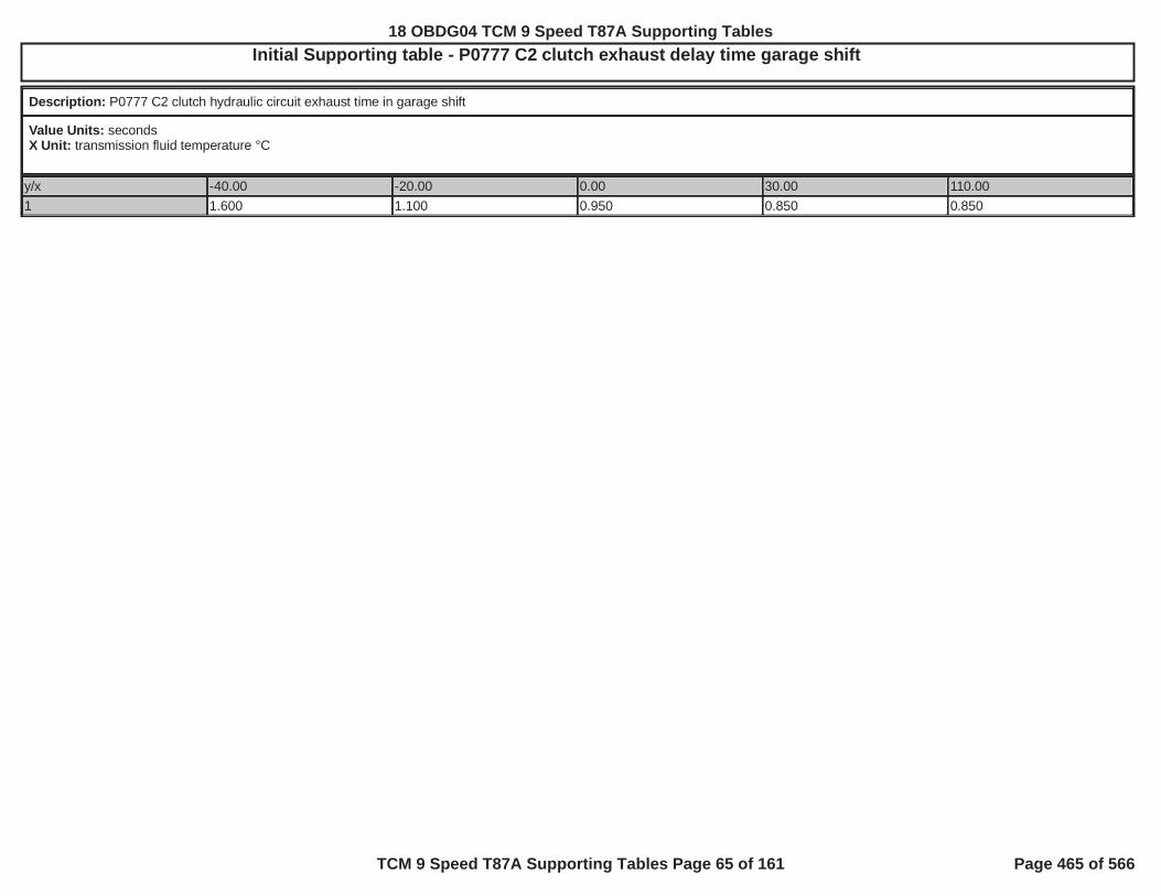
Initial Supporting table - P0777 C2 clutch exhaust delay time garage shift
Description: P0777 C2 clutch hydraulic circuit exhaust time in garage shift
Value Units: secondsX Unit: transmission fluid temperature °C
y/x -40.00 -20.00 0.00 30.00 110.001 1.600 1.100 0.950 0.850 0.850
18 OBDG04 TCM 9 Speed T87A Supporting Tables
TCM 9 Speed T87A Supporting Tables Page 65 of 161 Page 465 of 566

Initial Supporting table - P0777 C2 clutch exhaust delay time negative torque up shift
Description: P0777 C2 clutch hydraulic circuit exhaust time in negative torque up shift
Value Units: secondsX Unit: transmission fluid temperature °C
y/x -40.00 -20.00 0.00 30.00 110.001 0.500 0.500 0.500 0.500 0.500
18 OBDG04 TCM 9 Speed T87A Supporting Tables
TCM 9 Speed T87A Supporting Tables Page 66 of 161 Page 466 of 566

Initial Supporting table - P0777 C2 clutch exhaust delay time open throttle power down shift
Description: P0777 C2 clutch hydraulic circuit exhaust time in open throttle power down shift
Value Units: secondsX Unit: transmission fluid temperature °C
y/x -40.00 -20.00 0.00 30.00 110.001 1.600 1.100 0.950 0.212 0.212
18 OBDG04 TCM 9 Speed T87A Supporting Tables
TCM 9 Speed T87A Supporting Tables Page 67 of 161 Page 467 of 566

Initial Supporting table - P0777 C2 clutch exhaust delay time open throttle power on up shift
Description: P0777 C2 clutch hydraulic circuit exhaust time in open throttle power on up shift
Value Units: secondsX Unit: transmission fluid temperature °C
y/x -40.00 -20.00 0.00 30.00 110.001 3.100 0.900 0.800 0.700 0.262
18 OBDG04 TCM 9 Speed T87A Supporting Tables
TCM 9 Speed T87A Supporting Tables Page 68 of 161 Page 468 of 566

Initial Supporting table - P0797 C3 clutch exhaust delay time closed throttle down shift
Description: P0797 C3 clutch hydraulic circuit exhaust time in closed throttle down shift
Value Units: secondsX Unit: transmission fluid temperature °C
y/x -40.00 -20.00 0.00 30.00 110.001 1.300 1.000 0.950 0.469 0.200
18 OBDG04 TCM 9 Speed T87A Supporting Tables
TCM 9 Speed T87A Supporting Tables Page 69 of 161 Page 469 of 566

Initial Supporting table - P0797 C3 clutch exhaust delay time closed throttle lift foot up shift
Description: P0797 C3 clutch hydraulic circuit exhaust time in closed throttle lift foot up shift
Value Units: secondsX Unit: transmission fluid temperature °C
y/x -40.00 -20.00 0.00 30.00 110.001 1.600 1.100 0.950 0.850 0.850
18 OBDG04 TCM 9 Speed T87A Supporting Tables
TCM 9 Speed T87A Supporting Tables Page 70 of 161 Page 470 of 566

Initial Supporting table - P0797 C3 clutch exhaust delay time negative torque up shift
Description: P0797 C3 clutch hydraulic circuit exhaust time in negative torque up shift
Value Units: secondsX Unit: transmission fluid temperature °C
y/x -40.00 -20.00 0.00 30.00 110.001 0.500 0.500 0.500 0.500 0.500
18 OBDG04 TCM 9 Speed T87A Supporting Tables
TCM 9 Speed T87A Supporting Tables Page 71 of 161 Page 471 of 566

Initial Supporting table - P0797 C3 clutch exhaust delay time open throttle power down shift
Description: P0797 C3 clutch hydraulic circuit exhaust time in open throttle power down shift
Value Units: secondsX Unit: transmission fluid temperature °C
y/x -40.00 -20.00 0.00 30.00 110.001 1.600 1.100 0.950 0.387 0.144
18 OBDG04 TCM 9 Speed T87A Supporting Tables
TCM 9 Speed T87A Supporting Tables Page 72 of 161 Page 472 of 566

Initial Supporting table - P0797 C3 clutch exhaust delay time open throttle power on up shift
Description: P0797 C3 clutch hydraulic circuit exhaust time in open throttle power on up shift
Value Units: secondsX Unit: transmission fluid temperature °C
y/x -40.00 -20.00 0.00 30.00 110.001 1.900 0.800 0.750 0.650 0.256
18 OBDG04 TCM 9 Speed T87A Supporting Tables
TCM 9 Speed T87A Supporting Tables Page 73 of 161 Page 473 of 566

Initial Supporting table - P0797 C3clutch exhaust delay time garage shift
Description: P0797 C3 clutch hydraulic circuit exhaust time in garage shift
Value Units: secondsX Unit: transmission fluid temperature °C
y/x -40.00 -20.00 0.00 30.00 110.001 1.600 1.100 0.950 0.850 0.850
18 OBDG04 TCM 9 Speed T87A Supporting Tables
TCM 9 Speed T87A Supporting Tables Page 74 of 161 Page 474 of 566
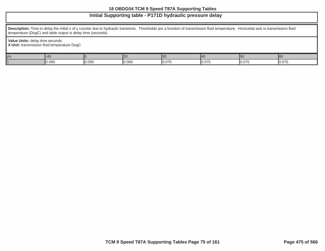
Initial Supporting table - P171D hydraulic pressure delay
Description: Time to delay the initial x of y counter due to hydraulic transients. Thresholds are a function of transmission fluid temperature. Horizontal axis is transmission fluidtemperature (DegC) and table output is delay time (seconds).
Value Units: delay time secondsX Unit: transmission fluid temperature DegC
y/x -40 0 20 30 40 50 601 0.090 0.090 0.080 0.075 0.075 0.075 0.075
18 OBDG04 TCM 9 Speed T87A Supporting Tables
TCM 9 Speed T87A Supporting Tables Page 75 of 161 Page 475 of 566

Initial Supporting table - P171D predicted turbine speed error
Description: Predicted turbine speed vs actual turbine speed error. Thresholds are a function of engine speed and transmission fliud temperature. Diagnostic is considered failing abovethese values. Table vertical axis is engine speed (RPM), horizontal axis is transmission fluid temperature (DegC) and table output is predicted turbine speed error (RPM).
Value Units: turbine speed RPM errorX Unit: transmission fluid temperature DegCY Units: engine speed RPM
y/x -40 0 10 20 400 350 350 350 350 350500 350 350 350 350 3501,100 350 350 350 350 3501,500 350 350 350 350 3502,500 350 350 350 350 350
18 OBDG04 TCM 9 Speed T87A Supporting Tables
TCM 9 Speed T87A Supporting Tables Page 76 of 161 Page 476 of 566

Initial Supporting table - P176B delay to allow transmission input, intermediate and output speeds to stablize for fail evaluation
Description: delay to allow transmission input, intermediate and output speeds to stablize for fail evaluation
Value Units: secondsX Unit: intermediate speed sensor select
y/x CeTSRR_e_C2C_ClchSpdSnsr1 CeTSRR_e_C2C_ClchSpdSnsr21 1.000 1.000
18 OBDG04 TCM 9 Speed T87A Supporting Tables
TCM 9 Speed T87A Supporting Tables Page 77 of 161 Page 477 of 566

Initial Supporting table - P176B holding clutch states
Description: inditaces when the clutch states allow transmission intermediate speed sensor evaluation, when rotating components can trigger speed sesnor, holding clutches will not allowevaluation while clutches not holding will allow evaluation
Value Units: TRUE or FALSEX Unit: intermediate speed sensor selectY Units: commanded gear
y/x CeTSRR_e_C2C_ClchSpdSnsr1 CeTSRR_e_C2C_ClchSpdSnsr2CeCGSR_e_CR_NullForSched 1 1CeCGSR_e_CR_Neutral 1 1CeCGSR_e_CR_Park 1 1CeCGSR_e_CR_Reverse 0 1CeCGSR_e_CR_First 0 1CeCGSR_e_CR_Second 0 1CeCGSR_e_CR_Third 1 1CeCGSR_e_CR_Fourth 0 1CeCGSR_e_CR_Fifth 0 1CeCGSR_e_CR_Sixth 0 1CeCGSR_e_CR_Seventh 0 1CeCGSR_e_CR_Eighth 1 1CeCGSR_e_CR_Ninth 0 1CeCGSR_e_CR_Tenth 1 1
18 OBDG04 TCM 9 Speed T87A Supporting Tables
TCM 9 Speed T87A Supporting Tables Page 78 of 161 Page 478 of 566

Initial Supporting table - P176B intermediate speed sensor fail count threshold
Description: P176B intermediate speed sensor fail count threshold
Value Units: fail countsX Unit: intermediate speed sensor select
y/x CeTSRR_e_C2C_ClchSpdSnsr1 CeTSRR_e_C2C_ClchSpdSnsr21 4 4
18 OBDG04 TCM 9 Speed T87A Supporting Tables
TCM 9 Speed T87A Supporting Tables Page 79 of 161 Page 479 of 566

Initial Supporting table - P176B intermediate speed sensor fail RPM threshold
Description:
Value Units: RPMX Unit: command gearY Units: intermediate speed sensor select
y/x CeTGRR_e_Gear1
CeTGRR_e_Gear2
CeTGRR_e_Gear3
CeTGRR_e_Gear4
CeTGRR_e_Gear5
CeTGRR_e_Gear6
CeTGRR_e_Gear7
CeTGRR_e_Gear8
CeTGRR_e_Gear9
CeTGRR_e_Gear10
CeTSRR_e_C2C_ClchSpdSnsr1
251 382 10,000 248 50 133 50 10,000 121 10,000
CeTSRR_e_C2C_ClchSpdSnsr2
0 0 0 0 0 0 0 0 0 0
18 OBDG04 TCM 9 Speed T87A Supporting Tables
TCM 9 Speed T87A Supporting Tables Page 80 of 161 Page 480 of 566
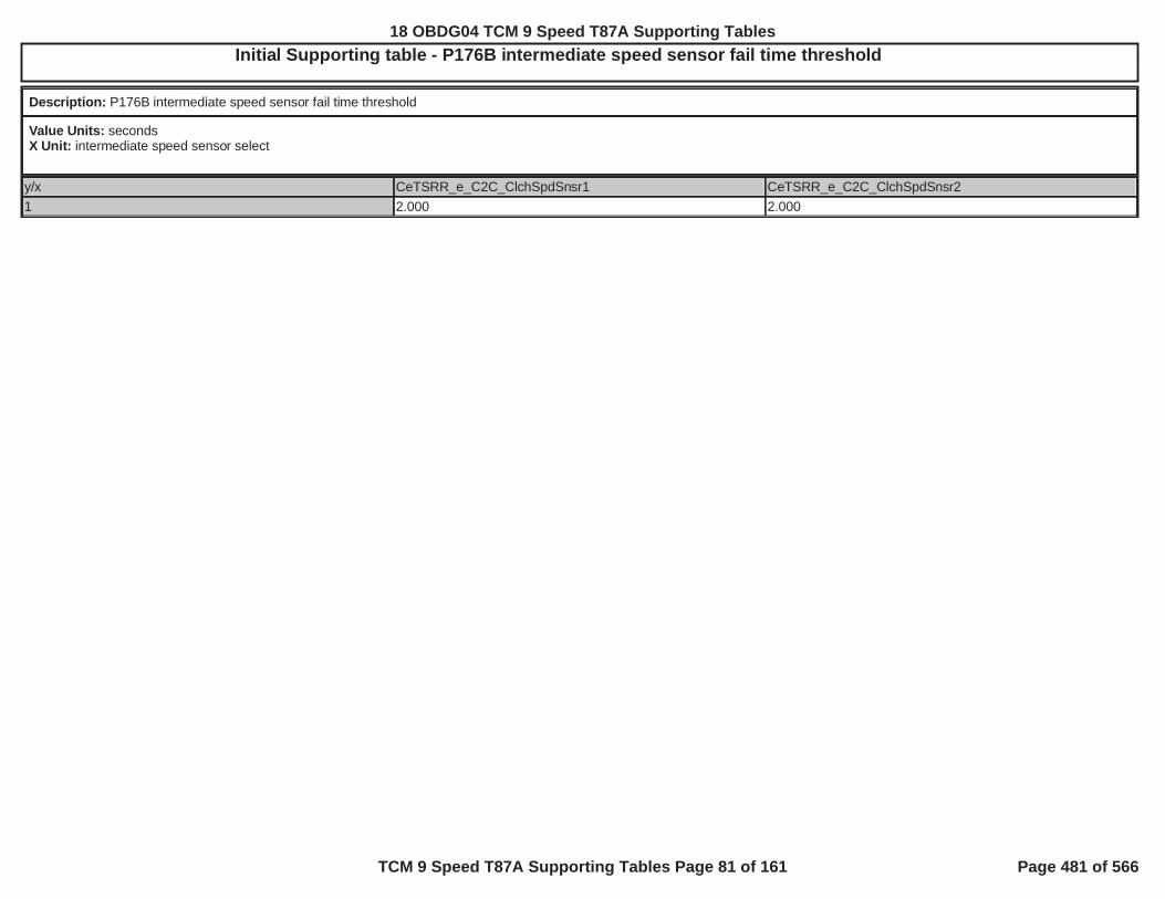
Initial Supporting table - P176B intermediate speed sensor fail time threshold
Description: P176B intermediate speed sensor fail time threshold
Value Units: secondsX Unit: intermediate speed sensor select
y/x CeTSRR_e_C2C_ClchSpdSnsr1 CeTSRR_e_C2C_ClchSpdSnsr21 2.000 2.000
18 OBDG04 TCM 9 Speed T87A Supporting Tables
TCM 9 Speed T87A Supporting Tables Page 81 of 161 Page 481 of 566

Initial Supporting table - P176B minimum estimated transmission intermediate speed to enable fail evaluation
Description: minimum estimated transmission intermediate speed to enable fail evaluation, where estimate is based on transmission input speed / ratio calibration, where ratio calibrationis either P176B ratio calibration when REVERSE or P176B ratio calibration when not REVERSE
Value Units: estimated transmission intermediate speed RPMX Unit: intermediate speed sensor select
y/x CeTSRR_e_C2C_ClchSpdSnsr1 CeTSRR_e_C2C_ClchSpdSnsr21 172.0 172.0
18 OBDG04 TCM 9 Speed T87A Supporting Tables
TCM 9 Speed T87A Supporting Tables Page 82 of 161 Page 482 of 566

Initial Supporting table - P176B minimum transmission input speed to enable fail evaluation
Description: minimum transmission input speed to enable fail evaluation
Value Units: transmission input speed RPMX Unit: intermediate speed sensor select
y/x CeTSRR_e_C2C_ClchSpdSnsr1 CeTSRR_e_C2C_ClchSpdSnsr21 172.0 172.0
18 OBDG04 TCM 9 Speed T87A Supporting Tables
TCM 9 Speed T87A Supporting Tables Page 83 of 161 Page 483 of 566

Initial Supporting table - P176B ratio calibration when not REVERSE
Description: used to estimate transmission input speed based on transmission intermediate speed when range is not REVERSE
Value Units: ratioX Unit: commanded gearY Units: intermediate speed sensor select
y/x CeTGRR_e_Gear1
CeTGRR_e_Gear2
CeTGRR_e_Gear3
CeTGRR_e_Gear4
CeTGRR_e_Gear5
CeTGRR_e_Gear6
CeTGRR_e_Gear7
CeTGRR_e_Gear8
CeTGRR_e_Gear9
CeTGRR_e_Gear10
CeTSRR_e_C2C_ClchSpdSnsr1
1.5848 6.3694 1.0000 2.4450 1.0000 0.5227 1.0000 1.0000 1.1905 1.0000
CeTSRR_e_C2C_ClchSpdSnsr2
1.0000 1.0000 1.0000 1.0000 1.0000 1.0000 1.0000 1.0000 1.0000 1.0000
18 OBDG04 TCM 9 Speed T87A Supporting Tables
TCM 9 Speed T87A Supporting Tables Page 84 of 161 Page 484 of 566
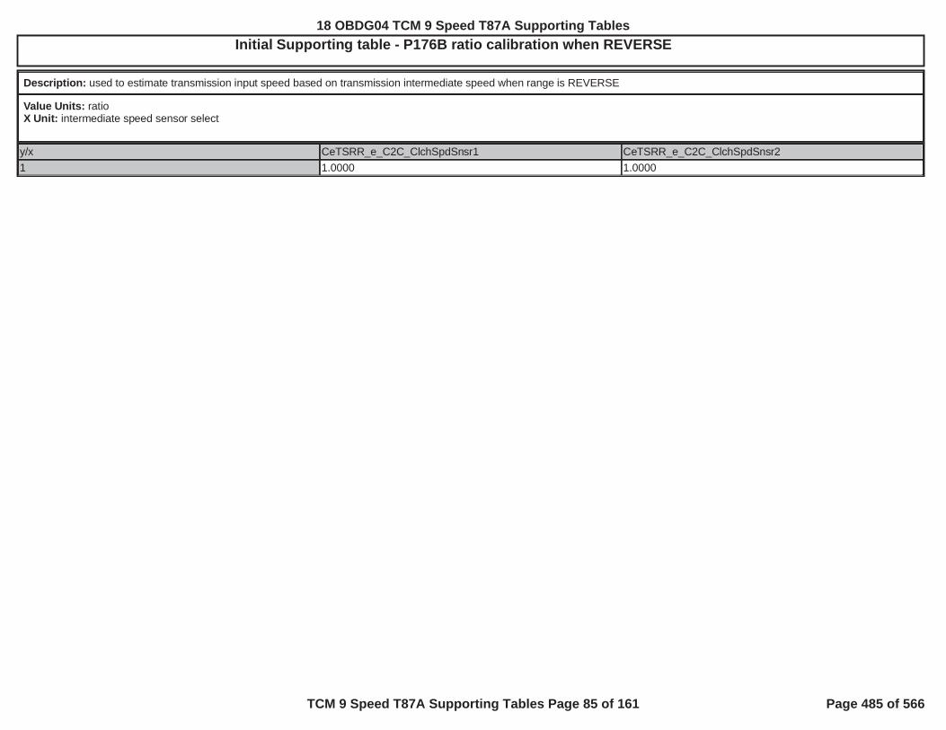
Initial Supporting table - P176B ratio calibration when REVERSE
Description: used to estimate transmission input speed based on transmission intermediate speed when range is REVERSE
Value Units: ratioX Unit: intermediate speed sensor select
y/x CeTSRR_e_C2C_ClchSpdSnsr1 CeTSRR_e_C2C_ClchSpdSnsr21 1.0000 1.0000
18 OBDG04 TCM 9 Speed T87A Supporting Tables
TCM 9 Speed T87A Supporting Tables Page 85 of 161 Page 485 of 566

Initial Supporting table - P17C5 P17D3 intermediate speed sensor RPM
Description: P17C5 P17D3 intermediate speed sensor RPM at signal period transtion to enable fail time update
Value Units: intermediate speed sensor RPMX Unit: intermediate speed sensor 1 or 2
y/x 0 11 25 25
18 OBDG04 TCM 9 Speed T87A Supporting Tables
TCM 9 Speed T87A Supporting Tables Page 86 of 161 Page 486 of 566

Initial Supporting table - P2715 C4 clutch exhaust delay time closed throttle down shift
Description: P2715 C4 clutch hydraulic circuit exhaust time in closed throttle down shift
Value Units: secondsX Unit: transmission fluid temperature °C
y/x -40.00 -20.00 0.00 30.00 110.001 1.400 0.750 0.700 0.663 0.225
18 OBDG04 TCM 9 Speed T87A Supporting Tables
TCM 9 Speed T87A Supporting Tables Page 87 of 161 Page 487 of 566

Initial Supporting table - P2715 C4 clutch exhaust delay time closed throttle lift foot up shift
Description: P2715 C4 clutch hydraulic circuit exhaust time in closed throttle lift foot up shift
Value Units: secondsX Unit: transmission fluid temperature °C
y/x -40.00 -20.00 0.00 30.00 110.001 1.600 1.100 0.950 0.850 0.850
18 OBDG04 TCM 9 Speed T87A Supporting Tables
TCM 9 Speed T87A Supporting Tables Page 88 of 161 Page 488 of 566

Initial Supporting table - P2715 C4 clutch exhaust delay time garage shift
Description: P2715 C4 clutch hydraulic circuit exhaust time in garage shift
Value Units: secondsX Unit: transmission fluid temperature °C
y/x -40.00 -20.00 0.00 30.00 110.001 1.600 1.100 0.950 0.850 0.850
18 OBDG04 TCM 9 Speed T87A Supporting Tables
TCM 9 Speed T87A Supporting Tables Page 89 of 161 Page 489 of 566

Initial Supporting table - P2715 C4 clutch exhaust delay time negative torque up shift
Description: P2715 C4 clutch hydraulic circuit exhaust time in negative torque up shift
Value Units: secondsX Unit: transmission fluid temperature °C
y/x -40.00 -20.00 0.00 30.00 110.001 0.500 0.500 0.500 0.500 0.500
18 OBDG04 TCM 9 Speed T87A Supporting Tables
TCM 9 Speed T87A Supporting Tables Page 90 of 161 Page 490 of 566

Initial Supporting table - P2715 C4 clutch exhaust delay time open throttle power down shift
Description: P2715 C4 clutch hydraulic circuit exhaust time in open throttle power down shift
Value Units: secondsX Unit: transmission fluid temperature °C
y/x -40.00 -20.00 0.00 30.00 110.001 1.600 1.100 0.950 0.119 0.119
18 OBDG04 TCM 9 Speed T87A Supporting Tables
TCM 9 Speed T87A Supporting Tables Page 91 of 161 Page 491 of 566

Initial Supporting table - P2715 C4 clutch exhaust delay time open throttle power on up shift
Description: P2715 C4 clutch hydraulic circuit exhaust time in open throttle power on up shift
Value Units: secondsX Unit: transmission fluid temperature °C
y/x -40.00 -20.00 0.00 30.00 110.001 1.900 0.650 0.600 0.550 0.300
18 OBDG04 TCM 9 Speed T87A Supporting Tables
TCM 9 Speed T87A Supporting Tables Page 92 of 161 Page 492 of 566

Initial Supporting table - P2724 C5 clutch exhaust delay time closed throttle down shift
Description: P2724 C5 clutch hydraulic circuit exhaust time in closed throttle down shift
Value Units: secondsX Unit: transmission fluid temperature °C
y/x -40.00 -20.00 0.00 30.00 110.001 1.700 1.369 1.100 0.650 0.337
18 OBDG04 TCM 9 Speed T87A Supporting Tables
TCM 9 Speed T87A Supporting Tables Page 93 of 161 Page 493 of 566

Initial Supporting table - P2724 C5 clutch exhaust delay time closed throttle lift foot up shift
Description: P2724 C5 clutch hydraulic circuit exhaust time in closed throttle lift foot up shift
Value Units: secondsX Unit: transmission fluid temperature °C
y/x -40.00 -20.00 0.00 30.00 110.001 1.600 1.100 0.950 0.850 0.850
18 OBDG04 TCM 9 Speed T87A Supporting Tables
TCM 9 Speed T87A Supporting Tables Page 94 of 161 Page 494 of 566

Initial Supporting table - P2724 C5 clutch exhaust delay time garage shift
Description: P2724 C5 clutch hydraulic circuit exhaust time in garage shift
Value Units: secondsX Unit: transmission fluid temperature °C
y/x -40 -20 0 30 1101 2 1 1 1 1
18 OBDG04 TCM 9 Speed T87A Supporting Tables
TCM 9 Speed T87A Supporting Tables Page 95 of 161 Page 495 of 566

Initial Supporting table - P2724 C5 clutch exhaust delay time negative torque up shift
Description: P0747 C1 clutch hydraulic circuit exhaust time in negative torque up shift
Value Units: secondsX Unit: transmission fluid temperature °C
y/x -40.00 -20.00 0.00 30.00 110.001 0.500 0.500 0.500 0.500 0.500
18 OBDG04 TCM 9 Speed T87A Supporting Tables
TCM 9 Speed T87A Supporting Tables Page 96 of 161 Page 496 of 566

Initial Supporting table - P2724 C5 clutch exhaust delay time open throttle power down shift
Description: P2724 C5 clutch hydraulic circuit exhaust time in open throttle power down shift
Value Units: secondsX Unit: transmission fluid temperature °C
y/x -40.00 -20.00 0.00 30.00 110.001 0.900 0.613 0.450 0.300 0.163
18 OBDG04 TCM 9 Speed T87A Supporting Tables
TCM 9 Speed T87A Supporting Tables Page 97 of 161 Page 497 of 566

Initial Supporting table - P2724 C5 clutch exhaust delay time open throttle power on up shift
Description: P2724 C5 clutch hydraulic circuit exhaust time in open throttle power on up shift
Value Units: secondsX Unit: transmission fluid temperature °C
y/x -40.00 -20.00 0.00 30.00 110.001 2.900 1.350 1.100 0.850 0.406
18 OBDG04 TCM 9 Speed T87A Supporting Tables
TCM 9 Speed T87A Supporting Tables Page 98 of 161 Page 498 of 566
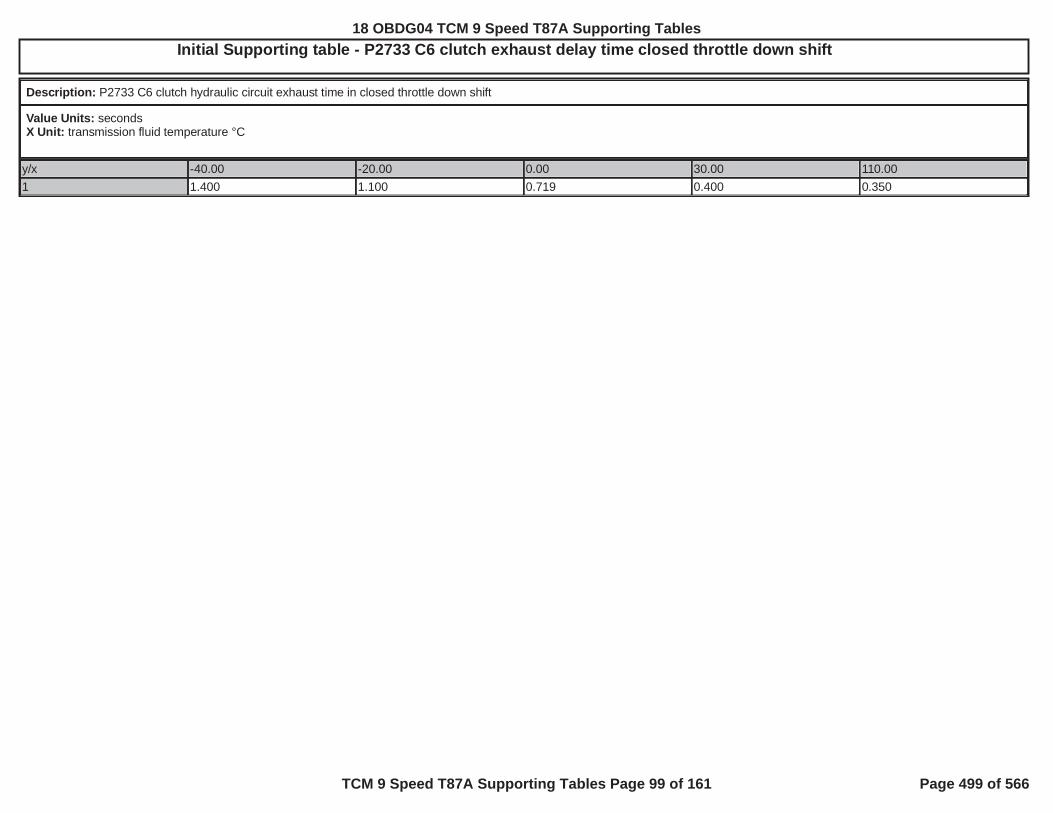
Initial Supporting table - P2733 C6 clutch exhaust delay time closed throttle down shift
Description: P2733 C6 clutch hydraulic circuit exhaust time in closed throttle down shift
Value Units: secondsX Unit: transmission fluid temperature °C
y/x -40.00 -20.00 0.00 30.00 110.001 1.400 1.100 0.719 0.400 0.350
18 OBDG04 TCM 9 Speed T87A Supporting Tables
TCM 9 Speed T87A Supporting Tables Page 99 of 161 Page 499 of 566

Initial Supporting table - P2733 C6 clutch exhaust delay time closed throttle lift foot up shift
Description: P2733 C6 clutch hydraulic circuit exhaust time in closed throttle lift foot up shift
Value Units: secondsX Unit: transmission fluid temperature °C
y/x -40.00 -20.00 0.00 30.00 110.001 1.600 1.100 0.950 0.850 0.850
18 OBDG04 TCM 9 Speed T87A Supporting Tables
TCM 9 Speed T87A Supporting Tables Page 100 of 161 Page 500 of 566

Initial Supporting table - P2733 C6 clutch exhaust delay time garage shift
Description: P2733 C6 clutch hydraulic circuit exhaust time in garage shift
Value Units: secondsX Unit: transmission fluid temperature °C
y/x -40.00 -20.00 0.00 30.00 110.001 1.600 1.100 0.950 0.850 0.850
18 OBDG04 TCM 9 Speed T87A Supporting Tables
TCM 9 Speed T87A Supporting Tables Page 101 of 161 Page 501 of 566
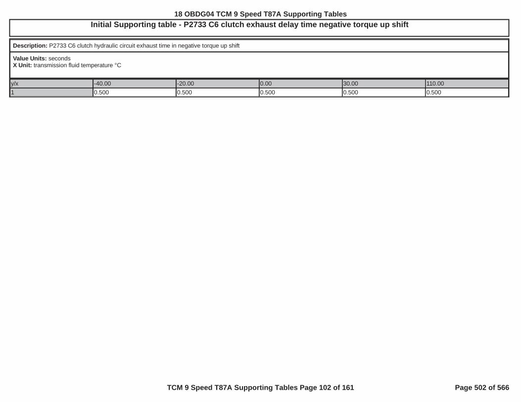
Initial Supporting table - P2733 C6 clutch exhaust delay time negative torque up shift
Description: P2733 C6 clutch hydraulic circuit exhaust time in negative torque up shift
Value Units: secondsX Unit: transmission fluid temperature °C
y/x -40.00 -20.00 0.00 30.00 110.001 0.500 0.500 0.500 0.500 0.500
18 OBDG04 TCM 9 Speed T87A Supporting Tables
TCM 9 Speed T87A Supporting Tables Page 102 of 161 Page 502 of 566

Initial Supporting table - P2733 C6 clutch exhaust delay time open throttle power down shift
Description: P2733 C6 clutch hydraulic circuit exhaust time in open throttle power down shift
Value Units: secondsX Unit: transmission fluid temperature °C
y/x -40.00 -20.00 0.00 30.00 110.001 0.850 0.350 0.300 0.238 0.131
18 OBDG04 TCM 9 Speed T87A Supporting Tables
TCM 9 Speed T87A Supporting Tables Page 103 of 161 Page 503 of 566
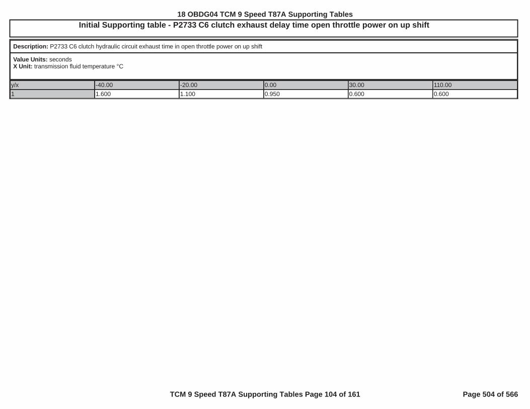
Initial Supporting table - P2733 C6 clutch exhaust delay time open throttle power on up shift
Description: P2733 C6 clutch hydraulic circuit exhaust time in open throttle power on up shift
Value Units: secondsX Unit: transmission fluid temperature °C
y/x -40.00 -20.00 0.00 30.00 110.001 1.600 1.100 0.950 0.600 0.600
18 OBDG04 TCM 9 Speed T87A Supporting Tables
TCM 9 Speed T87A Supporting Tables Page 104 of 161 Page 504 of 566
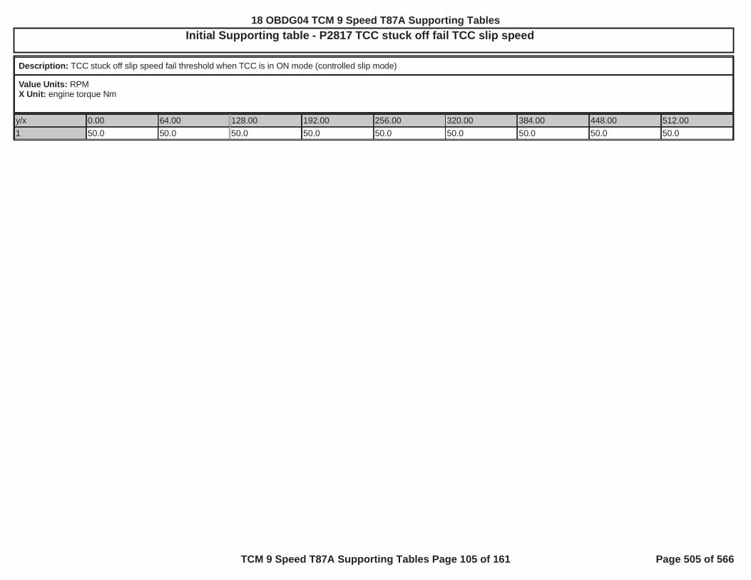
Initial Supporting table - P2817 TCC stuck off fail TCC slip speed
Description: TCC stuck off slip speed fail threshold when TCC is in ON mode (controlled slip mode)
Value Units: RPMX Unit: engine torque Nm
y/x 0.00 64.00 128.00 192.00 256.00 320.00 384.00 448.00 512.001 50.0 50.0 50.0 50.0 50.0 50.0 50.0 50.0 50.0
18 OBDG04 TCM 9 Speed T87A Supporting Tables
TCM 9 Speed T87A Supporting Tables Page 105 of 161 Page 505 of 566

Initial Supporting table - P2818 stuck on test time
Description: Value to initialize the TCC Stuck On test time to after transition of clutch select valve allowing TCC hydraulic circuit connectivity. Window is a time down window from thecalibration value to zero (0.0) seconds.
Value Units: secondsX Unit: transmission fluid temperature °C
y/x -7.00 10.00 40.001 1.500 1.250 1.000
18 OBDG04 TCM 9 Speed T87A Supporting Tables
TCM 9 Speed T87A Supporting Tables Page 106 of 161 Page 506 of 566

Initial Supporting table - P2818 torque convert derivative slip speed fail threshold
Description: The fail threshold, rate of change of torque converter slip speed, at which the torque convert clutch is considered stuck on.
Value Units: RPM/secondX Unit: transmission fluid temperature °C
y/x -7.00 10.00 40.000 -600.0 -600.0 -600.015 -600.0 -600.0 -600.025 -900.0 -900.0 -900.050 -1,200.0 -1,200.0 -1,200.075 -1,500.0 -1,500.0 -1,500.0
18 OBDG04 TCM 9 Speed T87A Supporting Tables
TCM 9 Speed T87A Supporting Tables Page 107 of 161 Page 507 of 566

Initial Supporting table - P2D2 Cltch Slip Sum
Description:
Value Units: dn output rpmX Unit: <brake gain> * brake pedal %Y Units: dn output speed threshold
y/x 0 15 20 30 35 50 75 88 1001 -8,192 -8,192 -8,192 -8,192 -8,192 -8,192 -8,192 -8,192 -8,192
18 OBDG04 TCM 9 Speed T87A Supporting Tables
TCM 9 Speed T87A Supporting Tables Page 108 of 161 Page 508 of 566

Initial Supporting table - P2D2 Cltch Slip Sum
Description:
Value Units: rate of change of output rpm (dn) per 25 millisecondsX Unit: % brake pedal positionY Units: not applicable, no units, single row table f(brake pedal position)
y/x 0 15 20 30 35 50 75 88 1001 -8,192 -8,192 -8,192 -8,192 -8,192 -8,192 -8,192 -8,192 -8,192
18 OBDG04 TCM 9 Speed T87A Supporting Tables
TCM 9 Speed T87A Supporting Tables Page 109 of 161 Page 509 of 566

Initial Supporting table - P2D2 Decel Pressure - C1
Description:
Value Units: KpaX Unit: Cmnd GearY Units: Kpa
P2D2 Decel Pressure - C1 - Part 1
y/x CeCGSR_e_NullForSched CeCGSR_e_NeutralNoClutch CeCGSR_e_NeutralC1 CeCGSR_e_NeutralC2 CeCGSR_e_NeutralC31 251 251 9,999 251 251
P2D2 Decel Pressure - C1 - Part 2
y/x CeCGSR_e_NeutralC4 CeCGSR_e_NeutralC5 CeCGSR_e_NeutralC6 CeCGSR_e_NeutralC7 CeCGSR_e_NeutralC1C21 251 251 251 251 9,999
P2D2 Decel Pressure - C1 - Part 3
y/x CeCGSR_e_NeutralC1C3 CeCGSR_e_NeutralC1C4 CeCGSR_e_NeutralC1C5 CeCGSR_e_NeutralC2C3 CeCGSR_e_NeutralC2C41 9,999 9,999 9,999 251 251
P2D2 Decel Pressure - C1 - Part 4
y/x CeCGSR_e_NeutralC2C5 CeCGSR_e_NeutralC2C6 CeCGSR_e_NeutralC3C4 CeCGSR_e_NeutralC3C5 CeCGSR_e_NeutralC3C61 251 251 251 251 251
P2D2 Decel Pressure - C1 - Part 5
y/x CeCGSR_e_NeutralC4C5 CeCGSR_e_NeutralC4C6 CeCGSR_e_NeutralC2C3C4C5
CeCGSR_e_Park_wNC CeCGSR_e_Park_wNC1
1 251 251 251 251 9,999
P2D2 Decel Pressure - C1 - Part 6
y/x CeCGSR_e_Park_wNC2 CeCGSR_e_Park_wNC3 CeCGSR_e_Park_wNC4 CeCGSR_e_Park_wNC5 CeCGSR_e_Park_wNC61 251 251 251 251 251
P2D2 Decel Pressure - C1 - Part 7
y/x CeCGSR_e_Park_wNC7 CeCGSR_e_Park_wNC1C2 CeCGSR_e_Park_wNC2C3 CeCGSR_e_Park_wNC2C4 CeCGSR_e_Park_wNC2C51 251 9,999 251 251 251
P2D2 Decel Pressure - C1 - Part 8
y/x CeCGSR_e_Park_wNC2C6 CeCGSR_e_Park_wNC3C4 CeCGSR_e_Park_wNC3C5 CeCGSR_e_Park_wNC3C6 CeCGSR_e_Park_wNC4C51 251 251 251 251 251
P2D2 Decel Pressure - C1 - Part 9
y/x CeCGSR_e_Park_wNC4C6 CeCGSR_e_Park_wNC2C3C4C5
CeCGSR_e_Reverse CeCGSR_e_FirstLckd CeCGSR_e_FirstFW
1 251 251 216 9,999 9,999
18 OBDG04 TCM 9 Speed T87A Supporting Tables
TCM 9 Speed T87A Supporting Tables Page 110 of 161 Page 510 of 566

Initial Supporting table - P2D2 Decel Pressure - C1
P2D2 Decel Pressure - C1 - Part 10
y/x CeCGSR_e_SecondLckd CeCGSR_e_SecondFW CeCGSR_e_Third CeCGSR_e_Fourth CeCGSR_e_Fifth1 9,999 9,999 9,999 9,999 9,999
P2D2 Decel Pressure - C1 - Part 11
y/x CeCGSR_e_Sixth CeCGSR_e_Seventh CeCGSR_e_Eighth CeCGSR_e_Ninth CeCGSR_e_Tenth1 9,999 1,056 671 564 251
P2D2 Decel Pressure - C1 - Part 12
y/x1
18 OBDG04 TCM 9 Speed T87A Supporting Tables
TCM 9 Speed T87A Supporting Tables Page 111 of 161 Page 511 of 566

Initial Supporting table - P2D2 Decel Pressure - C1
Description: clutch 1 command pressure threshold below which clutch 1 is considered released, such that, clutch 1 cannot carry enough clutch torque that would induce a vehicledeceleration above the design safety metric
Value Units: kPaX Unit: command gearY Units: not applicable, no units, single row table f(command gear)
P2D2 Decel Pressure - C1 - Part 1
y/x CeCGSR_e_NullForSched CeCGSR_e_NeutralNoClutch CeCGSR_e_NeutralC1 CeCGSR_e_NeutralC2 CeCGSR_e_NeutralC31 250.9 250.9 9,999.0 250.9 250.9
P2D2 Decel Pressure - C1 - Part 2
y/x CeCGSR_e_NeutralC4 CeCGSR_e_NeutralC5 CeCGSR_e_NeutralC6 CeCGSR_e_NeutralC7 CeCGSR_e_NeutralC1C21 250.9 250.9 250.9 250.9 9,999.0
P2D2 Decel Pressure - C1 - Part 3
y/x CeCGSR_e_NeutralC1C3 CeCGSR_e_NeutralC1C4 CeCGSR_e_NeutralC1C5 CeCGSR_e_NeutralC2C3 CeCGSR_e_NeutralC2C41 9,999.0 9,999.0 9,999.0 250.9 250.9
P2D2 Decel Pressure - C1 - Part 4
y/x CeCGSR_e_NeutralC2C5 CeCGSR_e_NeutralC2C6 CeCGSR_e_NeutralC3C4 CeCGSR_e_NeutralC3C5 CeCGSR_e_NeutralC3C61 250.9 250.9 250.9 250.9 250.9
P2D2 Decel Pressure - C1 - Part 5
y/x CeCGSR_e_NeutralC4C5 CeCGSR_e_NeutralC4C6 CeCGSR_e_NeutralC2C3C4C5
CeCGSR_e_Park_wNC CeCGSR_e_Park_wNC1
1 250.9 250.9 250.9 250.9 9,999.0
P2D2 Decel Pressure - C1 - Part 6
y/x CeCGSR_e_Park_wNC2 CeCGSR_e_Park_wNC3 CeCGSR_e_Park_wNC4 CeCGSR_e_Park_wNC5 CeCGSR_e_Park_wNC61 250.9 250.9 250.9 250.9 250.9
P2D2 Decel Pressure - C1 - Part 7
y/x CeCGSR_e_Park_wNC7 CeCGSR_e_Park_wNC1C2 CeCGSR_e_Park_wNC2C3 CeCGSR_e_Park_wNC2C4 CeCGSR_e_Park_wNC2C51 250.9 9,999.0 250.9 250.9 250.9
P2D2 Decel Pressure - C1 - Part 8
y/x CeCGSR_e_Park_wNC2C6 CeCGSR_e_Park_wNC3C4 CeCGSR_e_Park_wNC3C5 CeCGSR_e_Park_wNC3C6 CeCGSR_e_Park_wNC4C51 250.9 250.9 250.9 250.9 250.9
P2D2 Decel Pressure - C1 - Part 9
y/x CeCGSR_e_Park_wNC4C6 CeCGSR_e_Park_wNC2C3C4C5
CeCGSR_e_Reverse CeCGSR_e_FirstLckd CeCGSR_e_FirstFW
18 OBDG04 TCM 9 Speed T87A Supporting Tables
TCM 9 Speed T87A Supporting Tables Page 112 of 161 Page 512 of 566

Initial Supporting table - P2D2 Decel Pressure - C1
1 250.9 250.9 215.8 9,999.0 9,999.0
P2D2 Decel Pressure - C1 - Part 10
y/x CeCGSR_e_SecondLckd CeCGSR_e_SecondFW CeCGSR_e_Third CeCGSR_e_Fourth CeCGSR_e_Fifth1 9,999.0 9,999.0 9,999.0 9,999.0 9,999.0
P2D2 Decel Pressure - C1 - Part 11
y/x CeCGSR_e_Sixth CeCGSR_e_Seventh CeCGSR_e_Eighth CeCGSR_e_Ninth CeCGSR_e_Tenth1 9,999.0 1,055.9 671.3 564.3 250.9
P2D2 Decel Pressure - C1 - Part 12
y/x1
18 OBDG04 TCM 9 Speed T87A Supporting Tables
TCM 9 Speed T87A Supporting Tables Page 113 of 161 Page 513 of 566

Initial Supporting table - P2D2 Decel Pressure - C2
Description:
Value Units: KpaX Unit: Cmnd GearY Units: Kpa
P2D2 Decel Pressure - C2 - Part 1
y/x CeCGSR_e_NullForSched CeCGSR_e_NeutralNoClutch CeCGSR_e_NeutralC1 CeCGSR_e_NeutralC2 CeCGSR_e_NeutralC31 403 403 403 9,999 403
P2D2 Decel Pressure - C2 - Part 2
y/x CeCGSR_e_NeutralC4 CeCGSR_e_NeutralC5 CeCGSR_e_NeutralC6 CeCGSR_e_NeutralC7 CeCGSR_e_NeutralC1C21 403 403 403 403 9,999
P2D2 Decel Pressure - C2 - Part 3
y/x CeCGSR_e_NeutralC1C3 CeCGSR_e_NeutralC1C4 CeCGSR_e_NeutralC1C5 CeCGSR_e_NeutralC2C3 CeCGSR_e_NeutralC2C41 403 403 403 9,999 9,999
P2D2 Decel Pressure - C2 - Part 4
y/x CeCGSR_e_NeutralC2C5 CeCGSR_e_NeutralC2C6 CeCGSR_e_NeutralC3C4 CeCGSR_e_NeutralC3C5 CeCGSR_e_NeutralC3C61 9,999 9,999 403 403 403
P2D2 Decel Pressure - C2 - Part 5
y/x CeCGSR_e_NeutralC4C5 CeCGSR_e_NeutralC4C6 CeCGSR_e_NeutralC2C3C4C5
CeCGSR_e_Park_wNC CeCGSR_e_Park_wNC1
1 403 403 9,999 403 403
P2D2 Decel Pressure - C2 - Part 6
y/x CeCGSR_e_Park_wNC2 CeCGSR_e_Park_wNC3 CeCGSR_e_Park_wNC4 CeCGSR_e_Park_wNC5 CeCGSR_e_Park_wNC61 9,999 403 403 403 403
P2D2 Decel Pressure - C2 - Part 7
y/x CeCGSR_e_Park_wNC7 CeCGSR_e_Park_wNC1C2 CeCGSR_e_Park_wNC2C3 CeCGSR_e_Park_wNC2C4 CeCGSR_e_Park_wNC2C51 403 9,999 9,999 9,999 9,999
P2D2 Decel Pressure - C2 - Part 8
y/x CeCGSR_e_Park_wNC2C6 CeCGSR_e_Park_wNC3C4 CeCGSR_e_Park_wNC3C5 CeCGSR_e_Park_wNC3C6 CeCGSR_e_Park_wNC4C51 9,999 403 403 403 403
P2D2 Decel Pressure - C2 - Part 9
y/x CeCGSR_e_Park_wNC4C6 CeCGSR_e_Park_wNC2C3C4C5
CeCGSR_e_Reverse CeCGSR_e_FirstLckd CeCGSR_e_FirstFW
1 403 9,999 216 251 251
18 OBDG04 TCM 9 Speed T87A Supporting Tables
TCM 9 Speed T87A Supporting Tables Page 114 of 161 Page 514 of 566

Initial Supporting table - P2D2 Decel Pressure - C2
P2D2 Decel Pressure - C2 - Part 10
y/x CeCGSR_e_SecondLckd CeCGSR_e_SecondFW CeCGSR_e_Third CeCGSR_e_Fourth CeCGSR_e_Fifth1 9,999 9,999 471 721 1,648
P2D2 Decel Pressure - C2 - Part 11
y/x CeCGSR_e_Sixth CeCGSR_e_Seventh CeCGSR_e_Eighth CeCGSR_e_Ninth CeCGSR_e_Tenth1 719 1,056 671 9,999 403
P2D2 Decel Pressure - C2 - Part 12
y/x1
18 OBDG04 TCM 9 Speed T87A Supporting Tables
TCM 9 Speed T87A Supporting Tables Page 115 of 161 Page 515 of 566

Initial Supporting table - P2D2 Decel Pressure - C2
Description: clutch 2 command pressure threshold below which clutch 2 is considered released, such that, clutch 2 cannot carry enough clutch torque that would induce a vehicledeceleration above the design safety metric
Value Units: kPaX Unit: command gearY Units: not applicable, no units, single row table f(command gear)
P2D2 Decel Pressure - C2 - Part 1
y/x CeCGSR_e_NullForSched CeCGSR_e_NeutralNoClutch CeCGSR_e_NeutralC1 CeCGSR_e_NeutralC2 CeCGSR_e_NeutralC31 403 403 403 9,999 403
P2D2 Decel Pressure - C2 - Part 2
y/x CeCGSR_e_NeutralC4 CeCGSR_e_NeutralC5 CeCGSR_e_NeutralC6 CeCGSR_e_NeutralC7 CeCGSR_e_NeutralC1C21 403 403 403 403 9,999
P2D2 Decel Pressure - C2 - Part 3
y/x CeCGSR_e_NeutralC1C3 CeCGSR_e_NeutralC1C4 CeCGSR_e_NeutralC1C5 CeCGSR_e_NeutralC2C3 CeCGSR_e_NeutralC2C41 403 403 403 9,999 9,999
P2D2 Decel Pressure - C2 - Part 4
y/x CeCGSR_e_NeutralC2C5 CeCGSR_e_NeutralC2C6 CeCGSR_e_NeutralC3C4 CeCGSR_e_NeutralC3C5 CeCGSR_e_NeutralC3C61 9,999 9,999 403 403 403
P2D2 Decel Pressure - C2 - Part 5
y/x CeCGSR_e_NeutralC4C5 CeCGSR_e_NeutralC4C6 CeCGSR_e_NeutralC2C3C4C5
CeCGSR_e_Park_wNC CeCGSR_e_Park_wNC1
1 403 403 9,999 403 403
P2D2 Decel Pressure - C2 - Part 6
y/x CeCGSR_e_Park_wNC2 CeCGSR_e_Park_wNC3 CeCGSR_e_Park_wNC4 CeCGSR_e_Park_wNC5 CeCGSR_e_Park_wNC61 9,999 403 403 403 403
P2D2 Decel Pressure - C2 - Part 7
y/x CeCGSR_e_Park_wNC7 CeCGSR_e_Park_wNC1C2 CeCGSR_e_Park_wNC2C3 CeCGSR_e_Park_wNC2C4 CeCGSR_e_Park_wNC2C51 403 9,999 9,999 9,999 9,999
P2D2 Decel Pressure - C2 - Part 8
y/x CeCGSR_e_Park_wNC2C6 CeCGSR_e_Park_wNC3C4 CeCGSR_e_Park_wNC3C5 CeCGSR_e_Park_wNC3C6 CeCGSR_e_Park_wNC4C51 9,999 403 403 403 403
P2D2 Decel Pressure - C2 - Part 9
y/x CeCGSR_e_Park_wNC4C6 CeCGSR_e_Park_wNC2C3C4C5
CeCGSR_e_Reverse CeCGSR_e_FirstLckd CeCGSR_e_FirstFW
18 OBDG04 TCM 9 Speed T87A Supporting Tables
TCM 9 Speed T87A Supporting Tables Page 116 of 161 Page 516 of 566
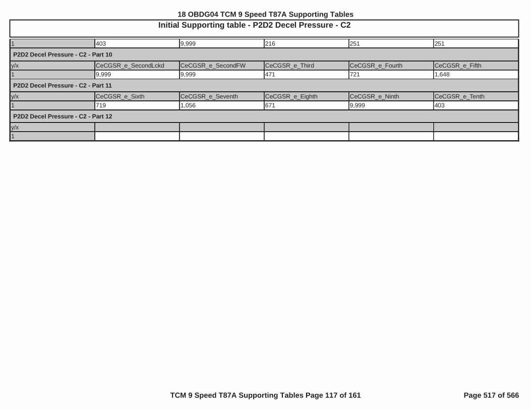
Initial Supporting table - P2D2 Decel Pressure - C2
1 403 9,999 216 251 251
P2D2 Decel Pressure - C2 - Part 10
y/x CeCGSR_e_SecondLckd CeCGSR_e_SecondFW CeCGSR_e_Third CeCGSR_e_Fourth CeCGSR_e_Fifth1 9,999 9,999 471 721 1,648
P2D2 Decel Pressure - C2 - Part 11
y/x CeCGSR_e_Sixth CeCGSR_e_Seventh CeCGSR_e_Eighth CeCGSR_e_Ninth CeCGSR_e_Tenth1 719 1,056 671 9,999 403
P2D2 Decel Pressure - C2 - Part 12
y/x1
18 OBDG04 TCM 9 Speed T87A Supporting Tables
TCM 9 Speed T87A Supporting Tables Page 117 of 161 Page 517 of 566

Initial Supporting table - P2D2 Decel Pressure - C3
Description:
Value Units: KpaX Unit: Cmnd GearY Units: Kpa
P2D2 Decel Pressure - C3 - Part 1
y/x CeCGSR_e_NullForSched CeCGSR_e_NeutralNoClutch CeCGSR_e_NeutralC1 CeCGSR_e_NeutralC2 CeCGSR_e_NeutralC31 471 471 471 471 9,999
P2D2 Decel Pressure - C3 - Part 2
y/x CeCGSR_e_NeutralC4 CeCGSR_e_NeutralC5 CeCGSR_e_NeutralC6 CeCGSR_e_NeutralC7 CeCGSR_e_NeutralC1C21 471 471 471 2,500 471
P2D2 Decel Pressure - C3 - Part 3
y/x CeCGSR_e_NeutralC1C3 CeCGSR_e_NeutralC1C4 CeCGSR_e_NeutralC1C5 CeCGSR_e_NeutralC2C3 CeCGSR_e_NeutralC2C41 9,999 471 471 9,999 471
P2D2 Decel Pressure - C3 - Part 4
y/x CeCGSR_e_NeutralC2C5 CeCGSR_e_NeutralC2C6 CeCGSR_e_NeutralC3C4 CeCGSR_e_NeutralC3C5 CeCGSR_e_NeutralC3C61 471 471 9,999 9,999 9,999
P2D2 Decel Pressure - C3 - Part 5
y/x CeCGSR_e_NeutralC4C5 CeCGSR_e_NeutralC4C6 CeCGSR_e_NeutralC2C3C4C5
CeCGSR_e_Park_wNC CeCGSR_e_Park_wNC1
1 471 471 9,999 471 471
P2D2 Decel Pressure - C3 - Part 6
y/x CeCGSR_e_Park_wNC2 CeCGSR_e_Park_wNC3 CeCGSR_e_Park_wNC4 CeCGSR_e_Park_wNC5 CeCGSR_e_Park_wNC61 471 9,999 471 471 471
P2D2 Decel Pressure - C3 - Part 7
y/x CeCGSR_e_Park_wNC7 CeCGSR_e_Park_wNC1C2 CeCGSR_e_Park_wNC2C3 CeCGSR_e_Park_wNC2C4 CeCGSR_e_Park_wNC2C51 471 471 9,999 471 471
P2D2 Decel Pressure - C3 - Part 8
y/x CeCGSR_e_Park_wNC2C6 CeCGSR_e_Park_wNC3C4 CeCGSR_e_Park_wNC3C5 CeCGSR_e_Park_wNC3C6 CeCGSR_e_Park_wNC4C51 471 9,999 9,999 9,999 471
P2D2 Decel Pressure - C3 - Part 9
y/x CeCGSR_e_Park_wNC4C6 CeCGSR_e_Park_wNC2C3C4C5
CeCGSR_e_Reverse CeCGSR_e_FirstLckd CeCGSR_e_FirstFW
1 471 9,999 216 251 251
18 OBDG04 TCM 9 Speed T87A Supporting Tables
TCM 9 Speed T87A Supporting Tables Page 118 of 161 Page 518 of 566

Initial Supporting table - P2D2 Decel Pressure - C3
P2D2 Decel Pressure - C3 - Part 10
y/x CeCGSR_e_SecondLckd CeCGSR_e_SecondFW CeCGSR_e_Third CeCGSR_e_Fourth CeCGSR_e_Fifth1 403 403 9,999 721 1,648
P2D2 Decel Pressure - C3 - Part 11
y/x CeCGSR_e_Sixth CeCGSR_e_Seventh CeCGSR_e_Eighth CeCGSR_e_Ninth CeCGSR_e_Tenth1 719 1,056 9,999 564 1,082
P2D2 Decel Pressure - C3 - Part 12
y/x1
18 OBDG04 TCM 9 Speed T87A Supporting Tables
TCM 9 Speed T87A Supporting Tables Page 119 of 161 Page 519 of 566

Initial Supporting table - P2D2 Decel Pressure - C3
Description: clutch 3 command pressure threshold below which clutch 3 is considered released, such that, clutch 3 cannot carry enough clutch torque that would induce a vehicledeceleration above the design safety metric
Value Units: kPaX Unit: command gearY Units: not applicable, no units, single row table f(command gear)
P2D2 Decel Pressure - C3 - Part 1
y/x CeCGSR_e_NullForSched CeCGSR_e_NeutralNoClutch CeCGSR_e_NeutralC1 CeCGSR_e_NeutralC2 CeCGSR_e_NeutralC31 471 471 471 471 9,999
P2D2 Decel Pressure - C3 - Part 2
y/x CeCGSR_e_NeutralC4 CeCGSR_e_NeutralC5 CeCGSR_e_NeutralC6 CeCGSR_e_NeutralC7 CeCGSR_e_NeutralC1C21 471 471 471 2,500 471
P2D2 Decel Pressure - C3 - Part 3
y/x CeCGSR_e_NeutralC1C3 CeCGSR_e_NeutralC1C4 CeCGSR_e_NeutralC1C5 CeCGSR_e_NeutralC2C3 CeCGSR_e_NeutralC2C41 9,999 471 471 9,999 471
P2D2 Decel Pressure - C3 - Part 4
y/x CeCGSR_e_NeutralC2C5 CeCGSR_e_NeutralC2C6 CeCGSR_e_NeutralC3C4 CeCGSR_e_NeutralC3C5 CeCGSR_e_NeutralC3C61 471 471 9,999 9,999 9,999
P2D2 Decel Pressure - C3 - Part 5
y/x CeCGSR_e_NeutralC4C5 CeCGSR_e_NeutralC4C6 CeCGSR_e_NeutralC2C3C4C5
CeCGSR_e_Park_wNC CeCGSR_e_Park_wNC1
1 471 471 9,999 471 471
P2D2 Decel Pressure - C3 - Part 6
y/x CeCGSR_e_Park_wNC2 CeCGSR_e_Park_wNC3 CeCGSR_e_Park_wNC4 CeCGSR_e_Park_wNC5 CeCGSR_e_Park_wNC61 471 9,999 471 471 471
P2D2 Decel Pressure - C3 - Part 7
y/x CeCGSR_e_Park_wNC7 CeCGSR_e_Park_wNC1C2 CeCGSR_e_Park_wNC2C3 CeCGSR_e_Park_wNC2C4 CeCGSR_e_Park_wNC2C51 471 471 9,999 471 471
P2D2 Decel Pressure - C3 - Part 8
y/x CeCGSR_e_Park_wNC2C6 CeCGSR_e_Park_wNC3C4 CeCGSR_e_Park_wNC3C5 CeCGSR_e_Park_wNC3C6 CeCGSR_e_Park_wNC4C51 471 9,999 9,999 9,999 471
P2D2 Decel Pressure - C3 - Part 9
y/x CeCGSR_e_Park_wNC4C6 CeCGSR_e_Park_wNC2C3C4C5
CeCGSR_e_Reverse CeCGSR_e_FirstLckd CeCGSR_e_FirstFW
18 OBDG04 TCM 9 Speed T87A Supporting Tables
TCM 9 Speed T87A Supporting Tables Page 120 of 161 Page 520 of 566

Initial Supporting table - P2D2 Decel Pressure - C3
1 471 9,999 216 251 251
P2D2 Decel Pressure - C3 - Part 10
y/x CeCGSR_e_SecondLckd CeCGSR_e_SecondFW CeCGSR_e_Third CeCGSR_e_Fourth CeCGSR_e_Fifth1 403 403 9,999 721 1,648
P2D2 Decel Pressure - C3 - Part 11
y/x CeCGSR_e_Sixth CeCGSR_e_Seventh CeCGSR_e_Eighth CeCGSR_e_Ninth CeCGSR_e_Tenth1 719 1,056 9,999 564 1,082
P2D2 Decel Pressure - C3 - Part 12
y/x1
18 OBDG04 TCM 9 Speed T87A Supporting Tables
TCM 9 Speed T87A Supporting Tables Page 121 of 161 Page 521 of 566

Initial Supporting table - P2D2 Decel Pressure - C4
Description:
Value Units: KpaX Unit: Cmnd GearY Units: Kpa
P2D2 Decel Pressure - C4 - Part 1
y/x CeCGSR_e_NullForSched CeCGSR_e_NeutralNoClutch CeCGSR_e_NeutralC1 CeCGSR_e_NeutralC2 CeCGSR_e_NeutralC31 721 721 721 721 721
P2D2 Decel Pressure - C4 - Part 2
y/x CeCGSR_e_NeutralC4 CeCGSR_e_NeutralC5 CeCGSR_e_NeutralC6 CeCGSR_e_NeutralC7 CeCGSR_e_NeutralC1C21 9,999 721 721 721 721
P2D2 Decel Pressure - C4 - Part 3
y/x CeCGSR_e_NeutralC1C3 CeCGSR_e_NeutralC1C4 CeCGSR_e_NeutralC1C5 CeCGSR_e_NeutralC2C3 CeCGSR_e_NeutralC2C41 721 9,999 721 721 9,999
P2D2 Decel Pressure - C4 - Part 4
y/x CeCGSR_e_NeutralC2C5 CeCGSR_e_NeutralC2C6 CeCGSR_e_NeutralC3C4 CeCGSR_e_NeutralC3C5 CeCGSR_e_NeutralC3C61 721 721 9,999 721 721
P2D2 Decel Pressure - C4 - Part 5
y/x CeCGSR_e_NeutralC4C5 CeCGSR_e_NeutralC4C6 CeCGSR_e_NeutralC2C3C4C5
CeCGSR_e_Park_wNC CeCGSR_e_Park_wNC1
1 9,999 9,999 9,999 721 721
P2D2 Decel Pressure - C4 - Part 6
y/x CeCGSR_e_Park_wNC2 CeCGSR_e_Park_wNC3 CeCGSR_e_Park_wNC4 CeCGSR_e_Park_wNC5 CeCGSR_e_Park_wNC61 721 721 9,999 721 721
P2D2 Decel Pressure - C4 - Part 7
y/x CeCGSR_e_Park_wNC7 CeCGSR_e_Park_wNC1C2 CeCGSR_e_Park_wNC2C3 CeCGSR_e_Park_wNC2C4 CeCGSR_e_Park_wNC2C51 721 721 721 9,999 721
P2D2 Decel Pressure - C4 - Part 8
y/x CeCGSR_e_Park_wNC2C6 CeCGSR_e_Park_wNC3C4 CeCGSR_e_Park_wNC3C5 CeCGSR_e_Park_wNC3C6 CeCGSR_e_Park_wNC4C51 721 9,999 721 721 9,999
P2D2 Decel Pressure - C4 - Part 9
y/x CeCGSR_e_Park_wNC4C6 CeCGSR_e_Park_wNC2C3C4C5
CeCGSR_e_Reverse CeCGSR_e_FirstLckd CeCGSR_e_FirstFW
1 9,999 9,999 216 251 251
18 OBDG04 TCM 9 Speed T87A Supporting Tables
TCM 9 Speed T87A Supporting Tables Page 122 of 161 Page 522 of 566

Initial Supporting table - P2D2 Decel Pressure - C4
P2D2 Decel Pressure - C4 - Part 10
y/x CeCGSR_e_SecondLckd CeCGSR_e_SecondFW CeCGSR_e_Third CeCGSR_e_Fourth CeCGSR_e_Fifth1 403 403 471 9,999 1,648
P2D2 Decel Pressure - C4 - Part 11
y/x CeCGSR_e_Sixth CeCGSR_e_Seventh CeCGSR_e_Eighth CeCGSR_e_Ninth CeCGSR_e_Tenth1 719 1,056 671 564 721
P2D2 Decel Pressure - C4 - Part 12
y/x1
18 OBDG04 TCM 9 Speed T87A Supporting Tables
TCM 9 Speed T87A Supporting Tables Page 123 of 161 Page 523 of 566

Initial Supporting table - P2D2 Decel Pressure - C4
Description: clutch 4 command pressure threshold below which clutch 4 is considered released, such that, clutch 4 cannot carry enough clutch torque that would induce a vehicledeceleration above the design safety metric
Value Units: kPaX Unit: command gearY Units: not applicable, no units, single row table f(command gear)
P2D2 Decel Pressure - C4 - Part 1
y/x CeCGSR_e_NullForSched CeCGSR_e_NeutralNoClutch CeCGSR_e_NeutralC1 CeCGSR_e_NeutralC2 CeCGSR_e_NeutralC31 721 721 721 721 721
P2D2 Decel Pressure - C4 - Part 2
y/x CeCGSR_e_NeutralC4 CeCGSR_e_NeutralC5 CeCGSR_e_NeutralC6 CeCGSR_e_NeutralC7 CeCGSR_e_NeutralC1C21 9,999 721 721 721 721
P2D2 Decel Pressure - C4 - Part 3
y/x CeCGSR_e_NeutralC1C3 CeCGSR_e_NeutralC1C4 CeCGSR_e_NeutralC1C5 CeCGSR_e_NeutralC2C3 CeCGSR_e_NeutralC2C41 721 9,999 721 721 9,999
P2D2 Decel Pressure - C4 - Part 4
y/x CeCGSR_e_NeutralC2C5 CeCGSR_e_NeutralC2C6 CeCGSR_e_NeutralC3C4 CeCGSR_e_NeutralC3C5 CeCGSR_e_NeutralC3C61 721 721 9,999 721 721
P2D2 Decel Pressure - C4 - Part 5
y/x CeCGSR_e_NeutralC4C5 CeCGSR_e_NeutralC4C6 CeCGSR_e_NeutralC2C3C4C5
CeCGSR_e_Park_wNC CeCGSR_e_Park_wNC1
1 9,999 9,999 9,999 721 721
P2D2 Decel Pressure - C4 - Part 6
y/x CeCGSR_e_Park_wNC2 CeCGSR_e_Park_wNC3 CeCGSR_e_Park_wNC4 CeCGSR_e_Park_wNC5 CeCGSR_e_Park_wNC61 721 721 9,999 721 721
P2D2 Decel Pressure - C4 - Part 7
y/x CeCGSR_e_Park_wNC7 CeCGSR_e_Park_wNC1C2 CeCGSR_e_Park_wNC2C3 CeCGSR_e_Park_wNC2C4 CeCGSR_e_Park_wNC2C51 721 721 721 9,999 721
P2D2 Decel Pressure - C4 - Part 8
y/x CeCGSR_e_Park_wNC2C6 CeCGSR_e_Park_wNC3C4 CeCGSR_e_Park_wNC3C5 CeCGSR_e_Park_wNC3C6 CeCGSR_e_Park_wNC4C51 721 9,999 721 721 9,999
P2D2 Decel Pressure - C4 - Part 9
y/x CeCGSR_e_Park_wNC4C6 CeCGSR_e_Park_wNC2C3C4C5
CeCGSR_e_Reverse CeCGSR_e_FirstLckd CeCGSR_e_FirstFW
18 OBDG04 TCM 9 Speed T87A Supporting Tables
TCM 9 Speed T87A Supporting Tables Page 124 of 161 Page 524 of 566

Initial Supporting table - P2D2 Decel Pressure - C4
1 9,999 9,999 216 251 251
P2D2 Decel Pressure - C4 - Part 10
y/x CeCGSR_e_SecondLckd CeCGSR_e_SecondFW CeCGSR_e_Third CeCGSR_e_Fourth CeCGSR_e_Fifth1 403 403 471 9,999 1,648
P2D2 Decel Pressure - C4 - Part 11
y/x CeCGSR_e_Sixth CeCGSR_e_Seventh CeCGSR_e_Eighth CeCGSR_e_Ninth CeCGSR_e_Tenth1 719 1,056 671 564 721
P2D2 Decel Pressure - C4 - Part 12
y/x1
18 OBDG04 TCM 9 Speed T87A Supporting Tables
TCM 9 Speed T87A Supporting Tables Page 125 of 161 Page 525 of 566

Initial Supporting table - P2D2 Decel Pressure - C5
Description:
Value Units: KpaX Unit: Cmnd GearY Units: Kpa
P2D2 Decel Pressure - C5 - Part 1
y/x CeCGSR_e_NullForSched CeCGSR_e_NeutralNoClutch CeCGSR_e_NeutralC1 CeCGSR_e_NeutralC2 CeCGSR_e_NeutralC31 719 719 719 719 719
P2D2 Decel Pressure - C5 - Part 2
y/x CeCGSR_e_NeutralC4 CeCGSR_e_NeutralC5 CeCGSR_e_NeutralC6 CeCGSR_e_NeutralC7 CeCGSR_e_NeutralC1C21 719 9,999 719 719 719
P2D2 Decel Pressure - C5 - Part 3
y/x CeCGSR_e_NeutralC1C3 CeCGSR_e_NeutralC1C4 CeCGSR_e_NeutralC1C5 CeCGSR_e_NeutralC2C3 CeCGSR_e_NeutralC2C41 719 719 9,999 719 719
P2D2 Decel Pressure - C5 - Part 4
y/x CeCGSR_e_NeutralC2C5 CeCGSR_e_NeutralC2C6 CeCGSR_e_NeutralC3C4 CeCGSR_e_NeutralC3C5 CeCGSR_e_NeutralC3C61 9,999 719 719 9,999 719
P2D2 Decel Pressure - C5 - Part 5
y/x CeCGSR_e_NeutralC4C5 CeCGSR_e_NeutralC4C6 CeCGSR_e_NeutralC2C3C4C5
CeCGSR_e_Park_wNC CeCGSR_e_Park_wNC1
1 9,999 719 9,999 719 719
P2D2 Decel Pressure - C5 - Part 6
y/x CeCGSR_e_Park_wNC2 CeCGSR_e_Park_wNC3 CeCGSR_e_Park_wNC4 CeCGSR_e_Park_wNC5 CeCGSR_e_Park_wNC61 719 719 719 9,999 719
P2D2 Decel Pressure - C5 - Part 7
y/x CeCGSR_e_Park_wNC7 CeCGSR_e_Park_wNC1C2 CeCGSR_e_Park_wNC2C3 CeCGSR_e_Park_wNC2C4 CeCGSR_e_Park_wNC2C51 719 719 719 719 9,999
P2D2 Decel Pressure - C5 - Part 8
y/x CeCGSR_e_Park_wNC2C6 CeCGSR_e_Park_wNC3C4 CeCGSR_e_Park_wNC3C5 CeCGSR_e_Park_wNC3C6 CeCGSR_e_Park_wNC4C51 719 719 9,999 719 9,999
P2D2 Decel Pressure - C5 - Part 9
y/x CeCGSR_e_Park_wNC4C6 CeCGSR_e_Park_wNC2C3C4C5
CeCGSR_e_Reverse CeCGSR_e_FirstLckd CeCGSR_e_FirstFW
1 719 9,999 9,999 251 251
18 OBDG04 TCM 9 Speed T87A Supporting Tables
TCM 9 Speed T87A Supporting Tables Page 126 of 161 Page 526 of 566

Initial Supporting table - P2D2 Decel Pressure - C5
P2D2 Decel Pressure - C5 - Part 10
y/x CeCGSR_e_SecondLckd CeCGSR_e_SecondFW CeCGSR_e_Third CeCGSR_e_Fourth CeCGSR_e_Fifth1 403 403 471 721 9,999
P2D2 Decel Pressure - C5 - Part 11
y/x CeCGSR_e_Sixth CeCGSR_e_Seventh CeCGSR_e_Eighth CeCGSR_e_Ninth CeCGSR_e_Tenth1 719 9,999 671 564 719
P2D2 Decel Pressure - C5 - Part 12
y/x1
18 OBDG04 TCM 9 Speed T87A Supporting Tables
TCM 9 Speed T87A Supporting Tables Page 127 of 161 Page 527 of 566

Initial Supporting table - P2D2 Decel Pressure - C5
Description: clutch 5 command pressure threshold below which clutch 5 is considered released, such that, clutch 5 cannot carry enough clutch torque that would induce a vehicledeceleration above the design safety metric
Value Units: kPaX Unit: command gearY Units: not applicable, no units, single row table f(command gear)
P2D2 Decel Pressure - C5 - Part 1
y/x CeCGSR_e_NullForSched CeCGSR_e_NeutralNoClutch CeCGSR_e_NeutralC1 CeCGSR_e_NeutralC2 CeCGSR_e_NeutralC31 719 719 719 719 719
P2D2 Decel Pressure - C5 - Part 2
y/x CeCGSR_e_NeutralC4 CeCGSR_e_NeutralC5 CeCGSR_e_NeutralC6 CeCGSR_e_NeutralC7 CeCGSR_e_NeutralC1C21 719 9,999 719 719 719
P2D2 Decel Pressure - C5 - Part 3
y/x CeCGSR_e_NeutralC1C3 CeCGSR_e_NeutralC1C4 CeCGSR_e_NeutralC1C5 CeCGSR_e_NeutralC2C3 CeCGSR_e_NeutralC2C41 719 719 9,999 719 719
P2D2 Decel Pressure - C5 - Part 4
y/x CeCGSR_e_NeutralC2C5 CeCGSR_e_NeutralC2C6 CeCGSR_e_NeutralC3C4 CeCGSR_e_NeutralC3C5 CeCGSR_e_NeutralC3C61 9,999 719 719 9,999 719
P2D2 Decel Pressure - C5 - Part 5
y/x CeCGSR_e_NeutralC4C5 CeCGSR_e_NeutralC4C6 CeCGSR_e_NeutralC2C3C4C5
CeCGSR_e_Park_wNC CeCGSR_e_Park_wNC1
1 9,999 719 9,999 719 719
P2D2 Decel Pressure - C5 - Part 6
y/x CeCGSR_e_Park_wNC2 CeCGSR_e_Park_wNC3 CeCGSR_e_Park_wNC4 CeCGSR_e_Park_wNC5 CeCGSR_e_Park_wNC61 719 719 719 9,999 719
P2D2 Decel Pressure - C5 - Part 7
y/x CeCGSR_e_Park_wNC7 CeCGSR_e_Park_wNC1C2 CeCGSR_e_Park_wNC2C3 CeCGSR_e_Park_wNC2C4 CeCGSR_e_Park_wNC2C51 719 719 719 719 9,999
P2D2 Decel Pressure - C5 - Part 8
y/x CeCGSR_e_Park_wNC2C6 CeCGSR_e_Park_wNC3C4 CeCGSR_e_Park_wNC3C5 CeCGSR_e_Park_wNC3C6 CeCGSR_e_Park_wNC4C51 719 719 9,999 719 9,999
P2D2 Decel Pressure - C5 - Part 9
y/x CeCGSR_e_Park_wNC4C6 CeCGSR_e_Park_wNC2C3C4C5
CeCGSR_e_Reverse CeCGSR_e_FirstLckd CeCGSR_e_FirstFW
18 OBDG04 TCM 9 Speed T87A Supporting Tables
TCM 9 Speed T87A Supporting Tables Page 128 of 161 Page 528 of 566
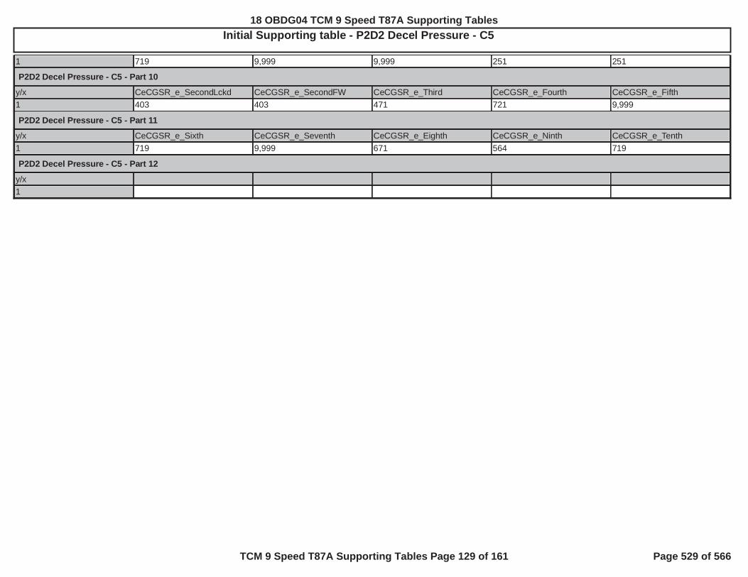
Initial Supporting table - P2D2 Decel Pressure - C5
1 719 9,999 9,999 251 251
P2D2 Decel Pressure - C5 - Part 10
y/x CeCGSR_e_SecondLckd CeCGSR_e_SecondFW CeCGSR_e_Third CeCGSR_e_Fourth CeCGSR_e_Fifth1 403 403 471 721 9,999
P2D2 Decel Pressure - C5 - Part 11
y/x CeCGSR_e_Sixth CeCGSR_e_Seventh CeCGSR_e_Eighth CeCGSR_e_Ninth CeCGSR_e_Tenth1 719 9,999 671 564 719
P2D2 Decel Pressure - C5 - Part 12
y/x1
18 OBDG04 TCM 9 Speed T87A Supporting Tables
TCM 9 Speed T87A Supporting Tables Page 129 of 161 Page 529 of 566

Initial Supporting table - P2D2 Decel Pressure - C6
Description:
Value Units: KpaX Unit: Cmnd GearY Units: Kpa
P2D2 Decel Pressure - C6 - Part 1
y/x CeCGSR_e_NullForSched CeCGSR_e_NeutralNoClutch CeCGSR_e_NeutralC1 CeCGSR_e_NeutralC2 CeCGSR_e_NeutralC31 494 494 494 494 494
P2D2 Decel Pressure - C6 - Part 2
y/x CeCGSR_e_NeutralC4 CeCGSR_e_NeutralC5 CeCGSR_e_NeutralC6 CeCGSR_e_NeutralC7 CeCGSR_e_NeutralC1C21 494 494 9,999 9,999 494
P2D2 Decel Pressure - C6 - Part 3
y/x CeCGSR_e_NeutralC1C3 CeCGSR_e_NeutralC1C4 CeCGSR_e_NeutralC1C5 CeCGSR_e_NeutralC2C3 CeCGSR_e_NeutralC2C41 494 494 494 494 494
P2D2 Decel Pressure - C6 - Part 4
y/x CeCGSR_e_NeutralC2C5 CeCGSR_e_NeutralC2C6 CeCGSR_e_NeutralC3C4 CeCGSR_e_NeutralC3C5 CeCGSR_e_NeutralC3C61 494 9,999 494 494 9,999
P2D2 Decel Pressure - C6 - Part 5
y/x CeCGSR_e_NeutralC4C5 CeCGSR_e_NeutralC4C6 CeCGSR_e_NeutralC2C3C4C5
CeCGSR_e_Park_wNC CeCGSR_e_Park_wNC1
1 494 9,999 494 494 494
P2D2 Decel Pressure - C6 - Part 6
y/x CeCGSR_e_Park_wNC2 CeCGSR_e_Park_wNC3 CeCGSR_e_Park_wNC4 CeCGSR_e_Park_wNC5 CeCGSR_e_Park_wNC61 494 494 494 494 9,999
P2D2 Decel Pressure - C6 - Part 7
y/x CeCGSR_e_Park_wNC7 CeCGSR_e_Park_wNC1C2 CeCGSR_e_Park_wNC2C3 CeCGSR_e_Park_wNC2C4 CeCGSR_e_Park_wNC2C51 494 494 494 494 494
P2D2 Decel Pressure - C6 - Part 8
y/x CeCGSR_e_Park_wNC2C6 CeCGSR_e_Park_wNC3C4 CeCGSR_e_Park_wNC3C5 CeCGSR_e_Park_wNC3C6 CeCGSR_e_Park_wNC4C51 9,999 494 494 9,999 494
P2D2 Decel Pressure - C6 - Part 9
y/x CeCGSR_e_Park_wNC4C6 CeCGSR_e_Park_wNC2C3C4C5
CeCGSR_e_Reverse CeCGSR_e_FirstLckd CeCGSR_e_FirstFW
1 9,999 494 9,999 251 251
18 OBDG04 TCM 9 Speed T87A Supporting Tables
TCM 9 Speed T87A Supporting Tables Page 130 of 161 Page 530 of 566

Initial Supporting table - P2D2 Decel Pressure - C6
P2D2 Decel Pressure - C6 - Part 10
y/x CeCGSR_e_SecondLckd CeCGSR_e_SecondFW CeCGSR_e_Third CeCGSR_e_Fourth CeCGSR_e_Fifth1 403 403 471 721 1,648
P2D2 Decel Pressure - C6 - Part 11
y/x CeCGSR_e_Sixth CeCGSR_e_Seventh CeCGSR_e_Eighth CeCGSR_e_Ninth CeCGSR_e_Tenth1 9,999 9,999 9,999 9,999 494
P2D2 Decel Pressure - C6 - Part 12
y/x1
18 OBDG04 TCM 9 Speed T87A Supporting Tables
TCM 9 Speed T87A Supporting Tables Page 131 of 161 Page 531 of 566

Initial Supporting table - P2D2 Decel Pressure - C6
Description: clutch 6 command pressure threshold below which clutch 6 is considered released, such that, clutch 6 cannot carry enough clutch torque that would induce a vehicledeceleration above the design safety metric
Value Units: kPaX Unit: command gearY Units: not applicable, no units, single row table f(command gear)
P2D2 Decel Pressure - C6 - Part 1
y/x CeCGSR_e_NullForSched CeCGSR_e_NeutralNoClutch CeCGSR_e_NeutralC1 CeCGSR_e_NeutralC2 CeCGSR_e_NeutralC31 494 494 494 494 494
P2D2 Decel Pressure - C6 - Part 2
y/x CeCGSR_e_NeutralC4 CeCGSR_e_NeutralC5 CeCGSR_e_NeutralC6 CeCGSR_e_NeutralC7 CeCGSR_e_NeutralC1C21 494 494 9,999 9,999 494
P2D2 Decel Pressure - C6 - Part 3
y/x CeCGSR_e_NeutralC1C3 CeCGSR_e_NeutralC1C4 CeCGSR_e_NeutralC1C5 CeCGSR_e_NeutralC2C3 CeCGSR_e_NeutralC2C41 494 494 494 494 494
P2D2 Decel Pressure - C6 - Part 4
y/x CeCGSR_e_NeutralC2C5 CeCGSR_e_NeutralC2C6 CeCGSR_e_NeutralC3C4 CeCGSR_e_NeutralC3C5 CeCGSR_e_NeutralC3C61 494 9,999 494 494 9,999
P2D2 Decel Pressure - C6 - Part 5
y/x CeCGSR_e_NeutralC4C5 CeCGSR_e_NeutralC4C6 CeCGSR_e_NeutralC2C3C4C5
CeCGSR_e_Park_wNC CeCGSR_e_Park_wNC1
1 494 9,999 494 494 494
P2D2 Decel Pressure - C6 - Part 6
y/x CeCGSR_e_Park_wNC2 CeCGSR_e_Park_wNC3 CeCGSR_e_Park_wNC4 CeCGSR_e_Park_wNC5 CeCGSR_e_Park_wNC61 494 494 494 494 9,999
P2D2 Decel Pressure - C6 - Part 7
y/x CeCGSR_e_Park_wNC7 CeCGSR_e_Park_wNC1C2 CeCGSR_e_Park_wNC2C3 CeCGSR_e_Park_wNC2C4 CeCGSR_e_Park_wNC2C51 494 494 494 494 494
P2D2 Decel Pressure - C6 - Part 8
y/x CeCGSR_e_Park_wNC2C6 CeCGSR_e_Park_wNC3C4 CeCGSR_e_Park_wNC3C5 CeCGSR_e_Park_wNC3C6 CeCGSR_e_Park_wNC4C51 9,999 494 494 9,999 494
P2D2 Decel Pressure - C6 - Part 9
y/x CeCGSR_e_Park_wNC4C6 CeCGSR_e_Park_wNC2C3C4C5
CeCGSR_e_Reverse CeCGSR_e_FirstLckd CeCGSR_e_FirstFW
18 OBDG04 TCM 9 Speed T87A Supporting Tables
TCM 9 Speed T87A Supporting Tables Page 132 of 161 Page 532 of 566

Initial Supporting table - P2D2 Decel Pressure - C6
1 9,999 494 9,999 251 251
P2D2 Decel Pressure - C6 - Part 10
y/x CeCGSR_e_SecondLckd CeCGSR_e_SecondFW CeCGSR_e_Third CeCGSR_e_Fourth CeCGSR_e_Fifth1 403 403 471 721 1,648
P2D2 Decel Pressure - C6 - Part 11
y/x CeCGSR_e_Sixth CeCGSR_e_Seventh CeCGSR_e_Eighth CeCGSR_e_Ninth CeCGSR_e_Tenth1 9,999 9,999 9,999 9,999 494
P2D2 Decel Pressure - C6 - Part 12
y/x1
18 OBDG04 TCM 9 Speed T87A Supporting Tables
TCM 9 Speed T87A Supporting Tables Page 133 of 161 Page 533 of 566
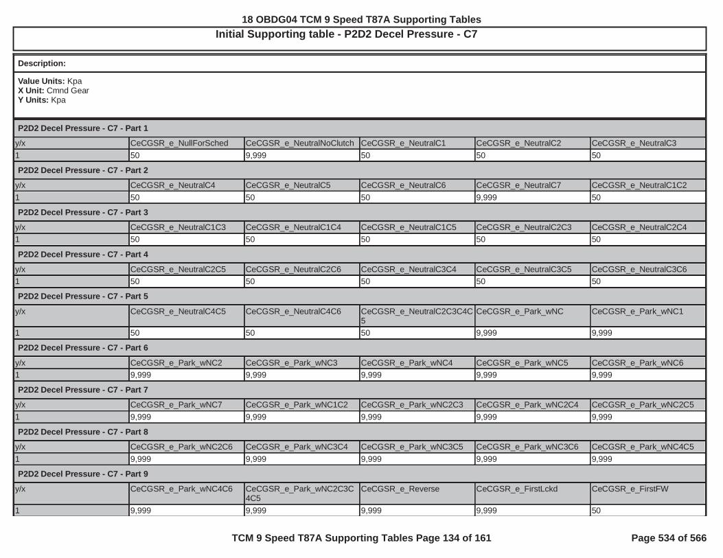
Initial Supporting table - P2D2 Decel Pressure - C7
Description:
Value Units: KpaX Unit: Cmnd GearY Units: Kpa
P2D2 Decel Pressure - C7 - Part 1
y/x CeCGSR_e_NullForSched CeCGSR_e_NeutralNoClutch CeCGSR_e_NeutralC1 CeCGSR_e_NeutralC2 CeCGSR_e_NeutralC31 50 9,999 50 50 50
P2D2 Decel Pressure - C7 - Part 2
y/x CeCGSR_e_NeutralC4 CeCGSR_e_NeutralC5 CeCGSR_e_NeutralC6 CeCGSR_e_NeutralC7 CeCGSR_e_NeutralC1C21 50 50 50 9,999 50
P2D2 Decel Pressure - C7 - Part 3
y/x CeCGSR_e_NeutralC1C3 CeCGSR_e_NeutralC1C4 CeCGSR_e_NeutralC1C5 CeCGSR_e_NeutralC2C3 CeCGSR_e_NeutralC2C41 50 50 50 50 50
P2D2 Decel Pressure - C7 - Part 4
y/x CeCGSR_e_NeutralC2C5 CeCGSR_e_NeutralC2C6 CeCGSR_e_NeutralC3C4 CeCGSR_e_NeutralC3C5 CeCGSR_e_NeutralC3C61 50 50 50 50 50
P2D2 Decel Pressure - C7 - Part 5
y/x CeCGSR_e_NeutralC4C5 CeCGSR_e_NeutralC4C6 CeCGSR_e_NeutralC2C3C4C5
CeCGSR_e_Park_wNC CeCGSR_e_Park_wNC1
1 50 50 50 9,999 9,999
P2D2 Decel Pressure - C7 - Part 6
y/x CeCGSR_e_Park_wNC2 CeCGSR_e_Park_wNC3 CeCGSR_e_Park_wNC4 CeCGSR_e_Park_wNC5 CeCGSR_e_Park_wNC61 9,999 9,999 9,999 9,999 9,999
P2D2 Decel Pressure - C7 - Part 7
y/x CeCGSR_e_Park_wNC7 CeCGSR_e_Park_wNC1C2 CeCGSR_e_Park_wNC2C3 CeCGSR_e_Park_wNC2C4 CeCGSR_e_Park_wNC2C51 9,999 9,999 9,999 9,999 9,999
P2D2 Decel Pressure - C7 - Part 8
y/x CeCGSR_e_Park_wNC2C6 CeCGSR_e_Park_wNC3C4 CeCGSR_e_Park_wNC3C5 CeCGSR_e_Park_wNC3C6 CeCGSR_e_Park_wNC4C51 9,999 9,999 9,999 9,999 9,999
P2D2 Decel Pressure - C7 - Part 9
y/x CeCGSR_e_Park_wNC4C6 CeCGSR_e_Park_wNC2C3C4C5
CeCGSR_e_Reverse CeCGSR_e_FirstLckd CeCGSR_e_FirstFW
1 9,999 9,999 9,999 9,999 50
18 OBDG04 TCM 9 Speed T87A Supporting Tables
TCM 9 Speed T87A Supporting Tables Page 134 of 161 Page 534 of 566

Initial Supporting table - P2D2 Decel Pressure - C7
P2D2 Decel Pressure - C7 - Part 10
y/x CeCGSR_e_SecondLckd CeCGSR_e_SecondFW CeCGSR_e_Third CeCGSR_e_Fourth CeCGSR_e_Fifth1 50 50 50 50 50
P2D2 Decel Pressure - C7 - Part 11
y/x CeCGSR_e_Sixth CeCGSR_e_Seventh CeCGSR_e_Eighth CeCGSR_e_Ninth CeCGSR_e_Tenth1 50 50 50 50 50
P2D2 Decel Pressure - C7 - Part 12
y/x1
18 OBDG04 TCM 9 Speed T87A Supporting Tables
TCM 9 Speed T87A Supporting Tables Page 135 of 161 Page 535 of 566

Initial Supporting table - P2D2 Decel Pressure - C7
Description: clutch 7 command pressure threshold below which clutch 7 is considered released, such that, clutch 7 cannot carry enough clutch torque that would induce a vehicledeceleration above the design safety metric
Value Units: kPaX Unit: command gearY Units: not applicable, no units, single row table f(command gear)
P2D2 Decel Pressure - C7 - Part 1
y/x CeCGSR_e_NullForSched CeCGSR_e_NeutralNoClutch CeCGSR_e_NeutralC1 CeCGSR_e_NeutralC2 CeCGSR_e_NeutralC31 50 9,999 50 50 50
P2D2 Decel Pressure - C7 - Part 2
y/x CeCGSR_e_NeutralC4 CeCGSR_e_NeutralC5 CeCGSR_e_NeutralC6 CeCGSR_e_NeutralC7 CeCGSR_e_NeutralC1C21 50 50 50 9,999 50
P2D2 Decel Pressure - C7 - Part 3
y/x CeCGSR_e_NeutralC1C3 CeCGSR_e_NeutralC1C4 CeCGSR_e_NeutralC1C5 CeCGSR_e_NeutralC2C3 CeCGSR_e_NeutralC2C41 50 50 50 50 50
P2D2 Decel Pressure - C7 - Part 4
y/x CeCGSR_e_NeutralC2C5 CeCGSR_e_NeutralC2C6 CeCGSR_e_NeutralC3C4 CeCGSR_e_NeutralC3C5 CeCGSR_e_NeutralC3C61 50 50 50 50 50
P2D2 Decel Pressure - C7 - Part 5
y/x CeCGSR_e_NeutralC4C5 CeCGSR_e_NeutralC4C6 CeCGSR_e_NeutralC2C3C4C5
CeCGSR_e_Park_wNC CeCGSR_e_Park_wNC1
1 50 50 50 9,999 9,999
P2D2 Decel Pressure - C7 - Part 6
y/x CeCGSR_e_Park_wNC2 CeCGSR_e_Park_wNC3 CeCGSR_e_Park_wNC4 CeCGSR_e_Park_wNC5 CeCGSR_e_Park_wNC61 9,999 9,999 9,999 9,999 9,999
P2D2 Decel Pressure - C7 - Part 7
y/x CeCGSR_e_Park_wNC7 CeCGSR_e_Park_wNC1C2 CeCGSR_e_Park_wNC2C3 CeCGSR_e_Park_wNC2C4 CeCGSR_e_Park_wNC2C51 9,999 9,999 9,999 9,999 9,999
P2D2 Decel Pressure - C7 - Part 8
y/x CeCGSR_e_Park_wNC2C6 CeCGSR_e_Park_wNC3C4 CeCGSR_e_Park_wNC3C5 CeCGSR_e_Park_wNC3C6 CeCGSR_e_Park_wNC4C51 9,999 9,999 9,999 9,999 9,999
P2D2 Decel Pressure - C7 - Part 9
y/x CeCGSR_e_Park_wNC4C6 CeCGSR_e_Park_wNC2C3C4C5
CeCGSR_e_Reverse CeCGSR_e_FirstLckd CeCGSR_e_FirstFW
18 OBDG04 TCM 9 Speed T87A Supporting Tables
TCM 9 Speed T87A Supporting Tables Page 136 of 161 Page 536 of 566

Initial Supporting table - P2D2 Decel Pressure - C7
1 9,999 9,999 9,999 9,999 50
P2D2 Decel Pressure - C7 - Part 10
y/x CeCGSR_e_SecondLckd CeCGSR_e_SecondFW CeCGSR_e_Third CeCGSR_e_Fourth CeCGSR_e_Fifth1 50 50 50 50 50
P2D2 Decel Pressure - C7 - Part 11
y/x CeCGSR_e_Sixth CeCGSR_e_Seventh CeCGSR_e_Eighth CeCGSR_e_Ninth CeCGSR_e_Tenth1 50 50 50 50 50
P2D2 Decel Pressure - C7 - Part 12
y/x1
18 OBDG04 TCM 9 Speed T87A Supporting Tables
TCM 9 Speed T87A Supporting Tables Page 137 of 161 Page 537 of 566

Initial Supporting table - transmission fluid temperature warm up time
Description:
Value Units: transmission fluid temperature normal warn up time, secondsX Unit: transmission fluid temperature at controller power up, °C
y/x -40.00 -30.00 -20.00 0.00 20.001 1,800.0 1,500.0 1,200.0 600.0 60.0
18 OBDG04 TCM 9 Speed T87A Supporting Tables
TCM 9 Speed T87A Supporting Tables Page 138 of 161 Page 538 of 566

Initial Supporting table - engine speed time for transmission hydraulic pressure available
Description: ime needed for engine speed to trigger "transmission hydraulic pressure available"
Value Units: secondsX Unit: transmission fluid temperature °C
y/x -40.00 -30.00 -20.00 0.00 40.001 0.300 0.300 0.275 0.200 0.100
18 OBDG04 TCM 9 Speed T87A Supporting Tables
TCM 9 Speed T87A Supporting Tables Page 139 of 161 Page 539 of 566

Initial Supporting table - KtPSDR_t_ModeVlvA_EngOff_Lim
Description: used for both engine off mode valve A stability delay time required to enable fail time update and fail time threshold
Value Units: secondsX Unit: transmission fluid temperature, degrees CelsiusY Units: unitless
y/x -40 -20 0 20 1301 0.650 0.650 0.650 0.650 0.650
18 OBDG04 TCM 9 Speed T87A Supporting Tables
TCM 9 Speed T87A Supporting Tables Page 140 of 161 Page 540 of 566

Initial Supporting table - KtPSDR_t_ModeVlvA_TurbDlyLim
Description: mode valve A transtion delay
Value Units: secondsX Unit: transmission fluid temperature, degrees CelsiusY Units: unitless
y/x -40 -20 0 20 1301 1.500 1.000 0.750 0.500 0.300
18 OBDG04 TCM 9 Speed T87A Supporting Tables
TCM 9 Speed T87A Supporting Tables Page 141 of 161 Page 541 of 566

Initial Supporting table - KtPSDR_t_ModeVlvB_EngOff_Lim
Description: used for both engine off mode valve B stability delay time required to enable fail time update and fail time threshold
Value Units: secondsX Unit: transmission fluid temperature, degrees Celsius
y/x -40 -20 0 20 1301 0.250 0.250 0.250 0.250 0.250
18 OBDG04 TCM 9 Speed T87A Supporting Tables
TCM 9 Speed T87A Supporting Tables Page 142 of 161 Page 542 of 566

Initial Supporting table - KtPSDR_t_ParkServo_EngOff_Lim
Description: P187E time engine must be not running to enable fail time update
Value Units: secondsX Unit: transmission fluid temperature, degrees CelsiusY Units: unitless
y/x -40.00 -20.00 0.00 20.00 130.001 0.250 0.250 0.250 0.250 0.250
18 OBDG04 TCM 9 Speed T87A Supporting Tables
TCM 9 Speed T87A Supporting Tables Page 143 of 161 Page 543 of 566

Initial Supporting table - KtPSDR_t_ParkStatDlyLim
Description: fail delay time
Value Units: secondsX Unit: transmission fluid temperature, degrees CelsiusY Units: unitless
y/x -40.00 -20.00 0.00 20.00 130.001 0.500 0.500 0.500 0.500 0.500
18 OBDG04 TCM 9 Speed T87A Supporting Tables
TCM 9 Speed T87A Supporting Tables Page 144 of 161 Page 544 of 566

Initial Supporting table - KtPSDR_t_ParkVlvStkOff_DlyLim
Description: P187E Transmission Park Valve Stuck Off fail enable delay time
Value Units: secondsX Unit: transmission fluid temperature, degrees CelsiusY Units: unitless
y/x -40.00 -20.00 0.00 20.00 130.001 1.250 1.250 1.250 1.250 1.250
18 OBDG04 TCM 9 Speed T87A Supporting Tables
TCM 9 Speed T87A Supporting Tables Page 145 of 161 Page 545 of 566

Initial Supporting table - KtPSDR_t_ParkVlvStkOn_DlyLim
Description: P187D Transmission Park Valve Stuck On fail enable delay time
Value Units: secondsX Unit: transmission fluid temperature, degrees CelsiusY Units: unitless
y/x -40.00 -20.00 0.00 20.00 130.001.00 1.250 1.250 1.250 1.250 1.250
18 OBDG04 TCM 9 Speed T87A Supporting Tables
TCM 9 Speed T87A Supporting Tables Page 146 of 161 Page 546 of 566

Initial Supporting table - KtPSDR_t_PISA_EngOff_Lim
Description: P18A8 fail time, engine not running
Value Units: secondsX Unit: transmission fluid temperature, degrees CelsiusY Units: unitless
y/x -40.00 -20.00 0.00 20.00 130.001 0.800 0.600 0.400 0.200 0.150
18 OBDG04 TCM 9 Speed T87A Supporting Tables
TCM 9 Speed T87A Supporting Tables Page 147 of 161 Page 547 of 566

Initial Supporting table - KtTMDC_t_EngOnHydPresThrsh
Description: hydraulic system pressure is available when engine speed is above engine speed threshold for this amount of time
Value Units: secondsX Unit: transmission fluid temperature, degrees CelsiusY Units: unitless
y/x -40.00 -30.00 -20.00 0.00 40.001 0.300 0.300 0.275 0.200 0.100
18 OBDG04 TCM 9 Speed T87A Supporting Tables
TCM 9 Speed T87A Supporting Tables Page 148 of 161 Page 548 of 566

Initial Supporting table - P0723 transmission engaged state time threshold
Description: time necessary after transmission engaged state indicates transmsision engaged to allow P0723 enable
Value Units: secondsX Unit: transmission fluid temperature °C
y/x -40.000 0.000 40.0001 5.000 3.000 1.000
18 OBDG04 TCM 9 Speed T87A Supporting Tables
TCM 9 Speed T87A Supporting Tables Page 149 of 161 Page 549 of 566
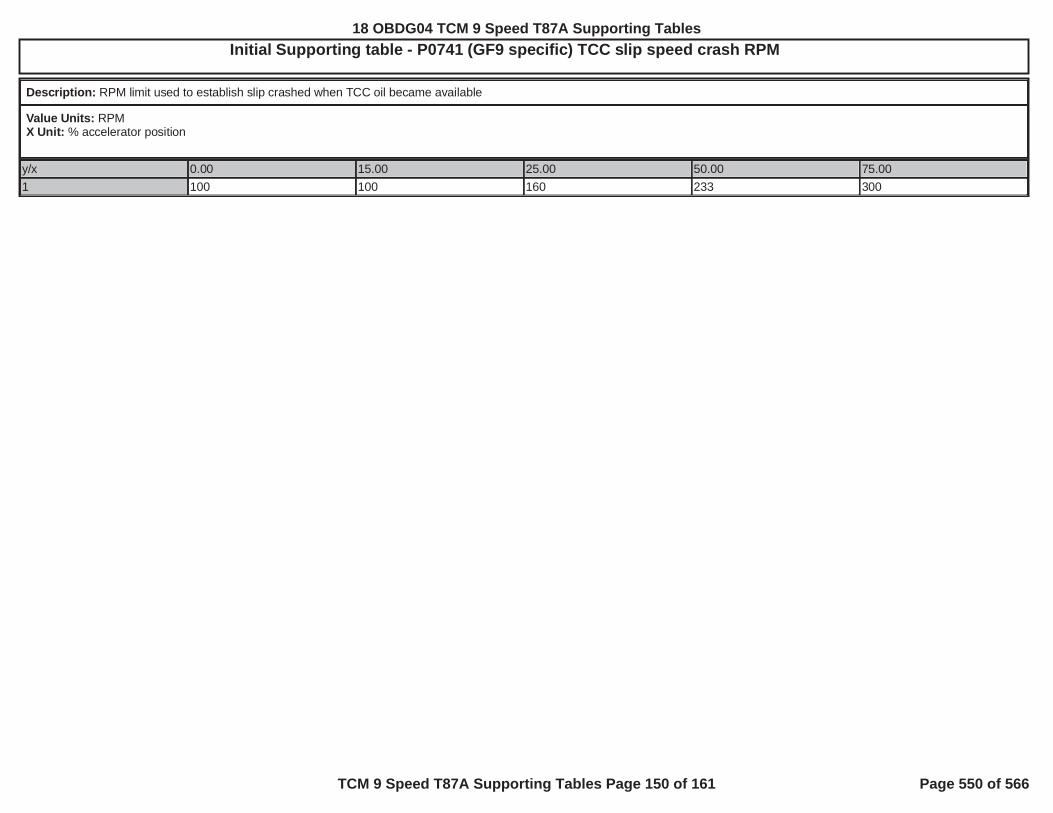
Initial Supporting table - P0741 (GF9 specific) TCC slip speed crash RPM
Description: RPM limit used to establish slip crashed when TCC oil became available
Value Units: RPMX Unit: % accelerator position
y/x 0.00 15.00 25.00 50.00 75.001 100 100 160 233 300
18 OBDG04 TCM 9 Speed T87A Supporting Tables
TCM 9 Speed T87A Supporting Tables Page 150 of 161 Page 550 of 566

Initial Supporting table - P0741 (GF9 specific) torque convert derivative slip speed fail threshold
Description: he fail threshold, rate of change of torque converter slip speed, at which the torque convert clutch is considered stuck on.
Value Units: RPM/secondX Unit: transmission fluid temperature °C
y/x -7.00 10.00 40.000 -600 -600 -60015 -600 -600 -60025 -900 -900 -90050 -1,200 -1,200 -1,20075 -1,500 -1,500 -1,500
18 OBDG04 TCM 9 Speed T87A Supporting Tables
TCM 9 Speed T87A Supporting Tables Page 151 of 161 Page 551 of 566

Initial Supporting table - P176B delay to allow transmission input, intermediate and output speeds to stablize for fail evaluation
Description: delay to allow transmission input, intermediate and output speeds to stablize for fail evaluation
Value Units: secondsX Unit: intermediate speed sensor select
y/x CeTSRR_e_C2C_ClchSpdSnsr1 CeTSRR_e_C2C_ClchSpdSnsr21 1.000 1.000
18 OBDG04 TCM 9 Speed T87A Supporting Tables
TCM 9 Speed T87A Supporting Tables Page 152 of 161 Page 552 of 566

Initial Supporting table - P176B holding clutch states
Description: inditaces when the clutch states allow transmission intermediate speed sensor evaluation, when rotating components can trigger speed sesnor, holding clutches will not allowevaluation while clutches not holding will allow evaluation
Value Units: TRUE or FALSEX Unit: intermediate speed sensor selectY Units: commanded gear
y/x CeTSRR_e_C2C_ClchSpdSnsr1 CeTSRR_e_C2C_ClchSpdSnsr2CeCGSR_e_CR_NullForSched 1 1CeCGSR_e_CR_Neutral 1 1CeCGSR_e_CR_Park 1 1CeCGSR_e_CR_Reverse 0 1CeCGSR_e_CR_First 0 1CeCGSR_e_CR_Second 0 1CeCGSR_e_CR_Third 1 1CeCGSR_e_CR_Fourth 0 1CeCGSR_e_CR_Fifth 0 1CeCGSR_e_CR_Sixth 0 1CeCGSR_e_CR_Seventh 0 1CeCGSR_e_CR_Eighth 1 1CeCGSR_e_CR_Ninth 0 1CeCGSR_e_CR_Tenth 1 1
18 OBDG04 TCM 9 Speed T87A Supporting Tables
TCM 9 Speed T87A Supporting Tables Page 153 of 161 Page 553 of 566
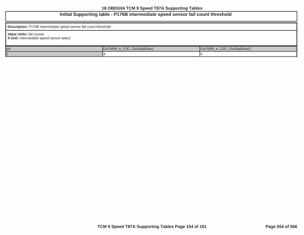
Initial Supporting table - P176B intermediate speed sensor fail count threshold
Description: P176B intermediate speed sensor fail count threshold
Value Units: fail countsX Unit: intermediate speed sensor select
y/x CeTSRR_e_C2C_ClchSpdSnsr1 CeTSRR_e_C2C_ClchSpdSnsr21 4 4
18 OBDG04 TCM 9 Speed T87A Supporting Tables
TCM 9 Speed T87A Supporting Tables Page 154 of 161 Page 554 of 566

Initial Supporting table - P176B intermediate speed sensor fail RPM threshold
Description:
Value Units: RPMX Unit: command gearY Units: intermediate speed sensor select
y/x CeTGRR_e_Gear1
CeTGRR_e_Gear2
CeTGRR_e_Gear3
CeTGRR_e_Gear4
CeTGRR_e_Gear5
CeTGRR_e_Gear6
CeTGRR_e_Gear7
CeTGRR_e_Gear8
CeTGRR_e_Gear9
CeTGRR_e_Gear10
CeTSRR_e_C2C_ClchSpdSnsr1
251 382 10,000 248 50 133 50 10,000 121 10,000
CeTSRR_e_C2C_ClchSpdSnsr2
0 0 0 0 0 0 0 0 0 0
18 OBDG04 TCM 9 Speed T87A Supporting Tables
TCM 9 Speed T87A Supporting Tables Page 155 of 161 Page 555 of 566

Initial Supporting table - P176B intermediate speed sensor fail time threshold
Description: P176B intermediate speed sensor fail time threshold
Value Units: secondsX Unit: intermediate speed sensor select
y/x CeTSRR_e_C2C_ClchSpdSnsr1 CeTSRR_e_C2C_ClchSpdSnsr21 2.000 2.000
18 OBDG04 TCM 9 Speed T87A Supporting Tables
TCM 9 Speed T87A Supporting Tables Page 156 of 161 Page 556 of 566

Initial Supporting table - P176B minimum estimated transmission intermediate speed to enable fail evaluation
Description: minimum estimated transmission intermediate speed to enable fail evaluation, where estimate is based on transmission input speed / ratio calibration, where ratio calibrationis either P176B ratio calibration when REVERSE or P176B ratio calibration when not REVERSE
Value Units: estimated transmission intermediate speed RPMX Unit: intermediate speed sensor select
y/x CeTSRR_e_C2C_ClchSpdSnsr1 CeTSRR_e_C2C_ClchSpdSnsr21 172.0 172.0
18 OBDG04 TCM 9 Speed T87A Supporting Tables
TCM 9 Speed T87A Supporting Tables Page 157 of 161 Page 557 of 566

Initial Supporting table - P176B minimum transmission input speed to enable fail evaluation
Description: minimum transmission input speed to enable fail evaluation
Value Units: transmission input speed RPMX Unit: intermediate speed sensor select
y/x CeTSRR_e_C2C_ClchSpdSnsr1 CeTSRR_e_C2C_ClchSpdSnsr21 172.0 172.0
18 OBDG04 TCM 9 Speed T87A Supporting Tables
TCM 9 Speed T87A Supporting Tables Page 158 of 161 Page 558 of 566

Initial Supporting table - P176B ratio calibration when not REVERSE
Description: used to estimate transmission input speed based on transmission intermediate speed when range is not REVERSE
Value Units: ratioX Unit: commanded gearY Units: intermediate speed sensor select
y/x CeTGRR_e_Gear1
CeTGRR_e_Gear2
CeTGRR_e_Gear3
CeTGRR_e_Gear4
CeTGRR_e_Gear5
CeTGRR_e_Gear6
CeTGRR_e_Gear7
CeTGRR_e_Gear8
CeTGRR_e_Gear9
CeTGRR_e_Gear10
CeTSRR_e_C2C_ClchSpdSnsr1
1.5848 6.3694 1.0000 2.4450 1.0000 0.5227 1.0000 1.0000 1.1905 1.0000
CeTSRR_e_C2C_ClchSpdSnsr2
1.0000 1.0000 1.0000 1.0000 1.0000 1.0000 1.0000 1.0000 1.0000 1.0000
18 OBDG04 TCM 9 Speed T87A Supporting Tables
TCM 9 Speed T87A Supporting Tables Page 159 of 161 Page 559 of 566

Initial Supporting table - P176B ratio calibration when REVERSE
Description: used to estimate transmission input speed based on transmission intermediate speed when range is REVERSE
Value Units: ratioX Unit: intermediate speed sensor select
y/x CeTSRR_e_C2C_ClchSpdSnsr1 CeTSRR_e_C2C_ClchSpdSnsr21 1.0000 1.0000
18 OBDG04 TCM 9 Speed T87A Supporting Tables
TCM 9 Speed T87A Supporting Tables Page 160 of 161 Page 560 of 566

Initial Supporting table - P17C5 P17D3 intermediate speed sensor RPM
Description: P17C5 P17D3 intermediate speed sensor RPM at signal period transtion to enable fail time update
Value Units: intermediate speed sensor RPMX Unit: intermediate speed sensor 1 or 2
y/x 0 11 25 25
18 OBDG04 TCM 9 Speed T87A Supporting Tables
TCM 9 Speed T87A Supporting Tables Page 161 of 161 Page 561 of 566
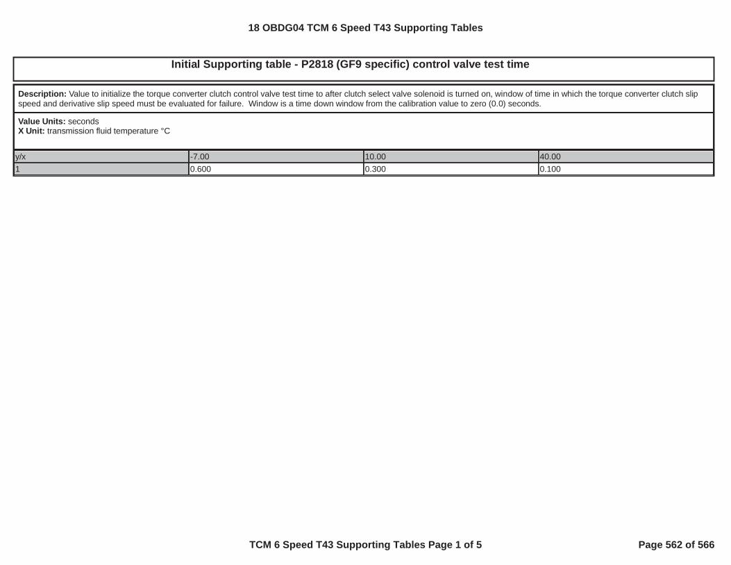
Initial Supporting table - P2818 (GF9 specific) control valve test time
Description: Value to initialize the torque converter clutch control valve test time to after clutch select valve solenoid is turned on, window of time in which the torque converter clutch slipspeed and derivative slip speed must be evaluated for failure. Window is a time down window from the calibration value to zero (0.0) seconds.
Value Units: secondsX Unit: transmission fluid temperature °C
y/x -7.00 10.00 40.001 0.600 0.300 0.100
18 OBDG04 TCM 6 Speed T43 Supporting Tables
TCM 6 Speed T43 Supporting Tables Page 1 of 5 Page 562 of 566

Table 1Axis 0.00 64.00 128.00 192.00 256.00 320.00 384.00 448.00 512.00 N*m
Curve 50.00 50.00 50.00 50.00 50.00 50.00 50.00 50.00 50.00 RPM
Table 2Axis -6.67 -6.66 40.00 ºC
Curve 409.59 2.00 2.00 Sec
Table 3Axis -6.67 -6.66 40.00 ºC
Curve 409.59 4.00 4.00 Sec
Table 4Axis -6.67 -6.66 40.00 ºC
Curve 409.59 2.00 2.00 Sec
Table 5Axis -6.67 -6.66 40.00 ºC
Curve 409.59 3.00 3.00 Sec
Table 6Axis -6.67 -6.66 40.00 80.00 120.00 ºC
Curve 409.00 3.60 1.60 1.40 1.40 Sec
2D Supporting Tables T43
18 OBDG04 TCM 6 Speed T43 Supporting Tables
TCM 6 Speed T43 Supporting Tables Page 2 of 5 Page 563 of 566

2D Supporting Tables T43
Table 7Axis -6.67 -6.66 40.00 80.00 120.00 ºC
Curve 409.00 3.40 1.40 1.30 1.20 Sec
Table 8Axis -6.67 -6.66 40.00 80.00 120.00 ºC
Curve 409.00 3.60 1.60 1.50 1.40 Sec
Table 9Axis -6.67 -6.66 40.00 80.00 120.00 ºC
Curve 409.00 3.30 1.30 1.20 1.10 Sec
Table 10Axis -6.67 -6.66 40.00 80.00 120.00 ºC
Curve 3.10 1.90 1.10 0.80 0.60 Sec
Table 11Axis -6.67 -6.66 40.00 80.00 120.00 ºC
Curve 1.80 1.20 0.60 0.40 0.30 Sec
Table 12Axis -6.67 -6.66 40.00 80.00 120.00 ºC
Curve 2.20 1.40 0.90 0.70 0.40 Sec
18 OBDG04 TCM 6 Speed T43 Supporting Tables
TCM 6 Speed T43 Supporting Tables Page 3 of 5 Page 564 of 566

2D Supporting Tables T43
Table 13Axis -6.67 -6.66 40.00 80.00 120.00 ºC
Curve 2.60 1.00 0.50 0.30 0.20 Sec
Table 14Axis -6.67 -6.66 40.00 80.00 120.00 ºC
Curve 3.00 0.90 0.50 0.30 0.20 Sec
Table 15Axis -40.00 -30.00 -20.00 -10.00 0.00 10.00 20.00 30.00 40.00 ºC
Curve 0.00 0.00 0.00 0.00 0.00 0.00 0.00 0.00 0.00 Sec
Table 16Axis -6.67 -6.66 40.00 ºC
Curve 409.59 2.50 2.50 Sec
Table 17Axis -6.67 -6.66 40.00 ºC
Curve 0.40 0.35 0.30 Sec
Table 18Axis -40.10 -40.00 -20.00 0.00 30.00 60.00 100.00 149.00 149.10 ºC
Curve 256.00 50.00 45.00 40.00 34.00 25.00 20.00 20.00 256.00 ºC
18 OBDG04 TCM 6 Speed T43 Supporting Tables
TCM 6 Speed T43 Supporting Tables Page 4 of 5 Page 565 of 566

2D Supporting Tables T43
Table 19Axis -40.10 -40.00 -20.00 0.00 30.00 60.00 100.00 149.00 149.10 ºC
Curve 256.00 50.00 45.00 40.00 34.00 25.00 20.00 20.00 256.00 ºC
Table 20Axis -40.10 -40.00 -20.00 0.00 30.00 60.00 100.00 149.00 149.10 ºC
Curve 256.00 10.00 8.00 8.00 8.00 8.00 8.00 8.00 256.00 ºC
Table 21Axis -40.00 -20.00 40.00 ºC
Curve 5.00 3.00 1.00 Sec
Table 22Axis -6.67 -6.66 40.00 ºC
Curve 8191.75 8191.75 8191.75 RPM/Sec
Table 23Axis -6.67 -6.66 40.00 ºC
Curve 8191.75 8191.75 8191.75 RPM/Sec
18 OBDG04 TCM 6 Speed T43 Supporting Tables
TCM 6 Speed T43 Supporting Tables Page 5 of 5 Page 566 of 566