172 Skyline Yarder - Madill 1/09983… · 172 Skyline Yarder Operator's Manual 099831- Page 1 of 87...
87
172 Skyline Yarder Operator's Manual 099831- Page 1 of 87 172 Skyline Yarder Operation Manual Table of Contents 1 PREFACE ........................................................................................................................................3 2 SAFETY PRECAUTIONS .............................................................................................................4 3 EMERGENCY ESCAPE .............................................................................................................. 12 4 GENERAL DESCRIPTION ....................................................................................................... 14 5 LEXAN & MARGUARD WINDOWS ...................................................................................... 23 6 YARDER DIMENSIONS............................................................................................................ 25 7 OPERATION ............................................................................................................................... 27 8 SEAT CONTROLS ...................................................................................................................... 29 9 CONTROL PANEL SWITCHES ............................................................................................... 30 10 CONTROL PANEL INDICATORS ........................................................................................... 32 11 ADDITIONAL CAB CONTROLS ............................................................................................. 34 12 YARDER OPERATION ............................................................................................................. 41 13 INSTALLING LINES .................................................................................................................. 46 14 RAISING AND TILTING SPAR ............................................................................................... 48 15 YARDING OPERATION ........................................................................................................... 51 16 YARDING METHODS ............................................................................................................... 53 17 LUBRICATION AND MAINTENANCE .................................................................................. 62 18 TROUBLESHOOTING .............................................................................................................. 74 19 ONBOARD DIAGNOSTICS - DDEC V .................................................................................... 77 20 TRANSMISSION DIAGNOSTIC TROUBLE CODES ........................................................... 82
-
Upload
nguyendien -
Category
Documents
-
view
236 -
download
2
Transcript of 172 Skyline Yarder - Madill 1/09983… · 172 Skyline Yarder Operator's Manual 099831- Page 1 of 87...
172 Skyline Yarder Operator's Manual 099831- Page 1 of 87
172 Skyline Yarder
Operation Manual
Table of Contents
1 PREFACE ........................................................................................................................................3
2 SAFETY PRECAUTIONS .............................................................................................................4
3 EMERGENCY ESCAPE .............................................................................................................. 12
4 GENERAL DESCRIPTION ....................................................................................................... 14
5 LEXAN & MARGUARD WINDOWS ...................................................................................... 23
6 YARDER DIMENSIONS............................................................................................................ 25
7 OPERATION ............................................................................................................................... 27
8 SEAT CONTROLS ...................................................................................................................... 29
9 CONTROL PANEL SWITCHES ............................................................................................... 30
10 CONTROL PANEL INDICATORS ........................................................................................... 32
11 ADDITIONAL CAB CONTROLS ............................................................................................. 34
12 YARDER OPERATION ............................................................................................................. 41
13 INSTALLING LINES .................................................................................................................. 46
14 RAISING AND TILTING SPAR ............................................................................................... 48
15 YARDING OPERATION ........................................................................................................... 51
16 YARDING METHODS ............................................................................................................... 53
17 LUBRICATION AND MAINTENANCE .................................................................................. 62
18 TROUBLESHOOTING .............................................................................................................. 74
19 ONBOARD DIAGNOSTICS - DDEC V .................................................................................... 77
20 TRANSMISSION DIAGNOSTIC TROUBLE CODES ........................................................... 82
172 Skyline Yarder Operator's Manual 099831- Page 2 of 87
Table of Figures Figure 1 – ECM & VIH Locations ............................................................................................ 7
Figure 2 - Air Amplifier & TCM Locations .............................................................................. 8
Figure 3 - Emergency Escape Removal .............................................................................. 12
Figure 4 - Emergency Escape Releases ............................................................................. 13
Figure 5 - Drum Capacities .................................................................................................... 17
Figure 6 - 172 Shaft Arrangement ........................................................................................ 19
Figure 7 - 172 Shipping Dimension ...................................................................................... 25
Figure 8 - 172 Working Dimensions ..................................................................................... 26
Figure 9 - Seat Control Locations ......................................................................................... 29
Figure 10 - Warning Light and Buzzer Operation ............................................................... 33
Figure 11 - 172 Yarder Controls ............................................................................................ 35
Figure 12 - Skyline Tension Chart ........................................................................................ 40
Figure 13 - Guyline Winch Colour Code .............................................................................. 43
Figure 14 - Guyline Positioning ............................................................................................. 44
Figure 15 - Guyline Safety Strap ........................................................................................... 46
Figure 16 - Maximum Yarding Angle .................................................................................... 52
Figure 17 - Typical Slackpuller Carriage .............................................................................. 55
Figure 18 - Slackpuller Rigging ............................................................................................. 58
Figure 19 - Slackpuller Arrangement.................................................................................... 59
Figure 20 - Shotgun Arrangement ........................................................................................ 61
Figure 21 - Lubrication Diagram............................................................................................ 67
Figure 22 - Transmission Filling and Checking Location .................................................. 70
Figure 23 - Track Carrier Maintenance ................................................................................ 72
Figure 24 - DDEC V System Diagnostic Codes ................................................................. 80
Figure 25 - DDEC V - Reading Codes ................................................................................. 81
172 Skyline Yarder Operator's Manual 099831- Page 3 of 87
1 Preface The operating and maintenance manual is designed to familiarize the operator of this machine with all the necessary information so that they may take full advantage of the capabilities built into the machine. If the machine is operated and maintained properly, it will yield profitable results. For this reason, it is imperative that the basic needs of the machine be satisfied. When the machine is lubricated with the recommended lubricants at the recommended intervals, abnormal part wear and failures will be avoided. Using the correct hydraulic oil for the prevailing temperatures and conditions, and careful maintenance of the hydraulic oil filters will help ensure a trouble free and dependable hydraulic system.
When ordering parts, please include the serial number of the machine. Also serviceable parts will be covered in the parts manual with the exception of the engine and the transmission, which will have their own Parts & Service manuals.
Note: Madill Equipment reserves the right to make technical changes on the machine without notice or incurring any liability where it simplifies or improves efficiency and productivity.
172 Skyline Yarder Operator's Manual 099831- Page 4 of 87
2 Safety Precautions
2.1 General Safety Precautions
The following are some safety tips that you should follow when operating the 172 Skyline Yarder for the protection of the people who work around you and for your own protection.
2.1.1 Before you start
Know your machine. Inspect it thoroughly. Keep it clean. Wear close fitting clothing and protective items. Make sure protective guards are in place. Check height, weight and width restrictions for your work area. Be sure you know about any hazards. Make sure you agree with your signal person on hand signals.
NOTE: This machine is designed to operate on prepared landings with slopes not more than 20%
2.1.2 Starting Up
Make sure all controls are in proper position for starting. Check for warning tags. Start the machine only from the operator’s cab and do not leave the cab while the engine is running. Warm the machine up gradually. Practice with the function controls. Report any unusual noises or conditions for immediate repair. Stop accidents before they stop you!
NOTE: Allow air pressure to reach 120 Psi before operating the winch.
2.1.3 While Operating
PAY ATTENTION! Know the working range of your machine. Know where any obstructions might be. Do not move the machine unnecessarily fast. Be sure everyone is in the clear before moving any part of the machine. Never swing or position any attachment or load over ground crew or truck cab. Never allow any-one to ride on any attachment or load. Never attempt to operate the machine from any position outside the operator’s cab. Never operate in a location where the machine or load may contact electric power lines. ALWAYS operate with seat belt fastened.
2.1.4 While Travelling
Make sure that no one is endangered before you make your move. Never get on or off the machine while it is in motion. Cross obstacles at an angle and at low speed. Watch to see that your boom clears all obstacles. Shift the transmission and yarding control to neutral. This machine is designed to operate on prepared landings with slopes not more than 20%.

172 Skyline Yarder Operator's Manual 099831- Page 5 of 87
2.1.5 Before Performing Service
Slack lines, shut off engine and remove keys from ignition. Attach a “DO NOT OPERATE” tag in an obvious place in operator’s cab. And lock out the Night Switch located in the battery box.
2.1.6 Overloading
Overloading is hazardous. Make certain you are within the safe load and limits of your machine for prevailing conditions. Overloading the machine can result in rollover which may cause serious injury or death, damage or an increased rate of wear that will not be covered by warranty.
2.1.7 Fire prevention
Due to the operating conditions found in mechanized logging there are significant fire hazards that can arise over time if the equipment is not kept clean and well maintained on a continual basis. In order to minimize the fire hazards present on the machine it is important to reduce or eliminate both potential sources of fuel for a fire and potential sources of ignition. Sources of fuel can accumulate due to normal operation, service or component failure. These include such materials as needles, leaves, bark, wood chips, sawdust, hydraulic oil, grease and fuel. Sources of ignition include overheating engine and hydraulic components, exhaust components, and sparks due to damage to the electrical system.
The following precautions must be taken for the safe operation of the machine:
• Accumulation of needles, leaves, bark, wood chips, sawdust or other debris must be removed daily.
• Hydraulic leaks, accumulations of grease, fuel or oil must be repaired and cleaned up immediately.
• Electrical wires, battery cables, hydraulic hoses and fuel lines must be inspected daily and replaced immediately if damaged or worn.
• The radiator and engine cooling system should be cleaned and serviced daily to maintain moderate engine temperatures.
• Ensure a fire extinguisher and other required firefighting equipment are on the machine and properly maintained.
• When welding on the machine, ensure that the area to be welded has been thoroughly cleaned of any flammable materials and that a fire extinguisher is within close reach.
• Refuel the machine only after the engine has been stopped and allowed to cool down.
172 Skyline Yarder Operator's Manual 099831- Page 6 of 87
For machines with an automatic fire suppression system the following precautions are required to ensure maximum effectiveness:
• The house must be kept down with all access doors closed while the machine is running except when required for service, maintenance and inspections.
• If a fire is detected before the system has discharged, activate the system manually.
• DO NOT wait for the system to automatically activate.
• In the event of a fire while the house is open, immediately close the house after ensuring that all personnel are clear of the area. Once closed, manually activate fire suppression system.
2.1.8 Safe Winch Operation
Do not use the machine for operations other than it was intended. This machine is designed as a log yarder, to be operated within the parameters specified in this manual. Any other use must be approved by the manufacturer.
Do not operate the machine if inspection reveals any structural damage to the spar, gantry legs or their anchor points. Inspect these parts on a regular basis, at the monthly greasing intervals or more frequently.
Do not leave the machine with a load suspended in the air. Exception: The unloaded grapple or carriage may be “parked” in the air overnight with the winch spring-brakes (“maxies”) set, but only if it can be determined that this will not create a hazard for anyone in, or passing by the area.
2.1.9 Welding Precautions
To prevent damage to the electronic control systems on this machine, the following steps must be taken before welding:
1. Battery - disconnect both the positive and negative terminals.
2. Engine Control Module (ECM) – Disconnect the plug to the ECM on the engine. The ECM is located at the rear of the machine.
172 Skyline Yarder Operator's Manual 099831- Page 7 of 87
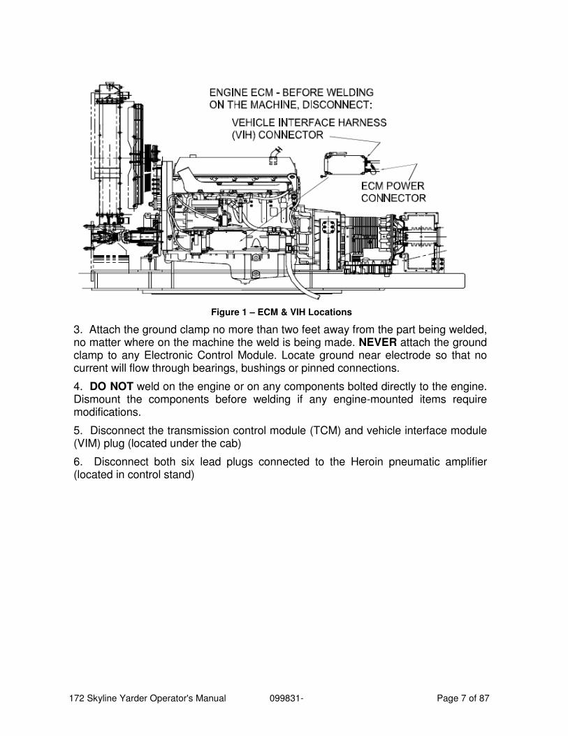
Figure 1 – ECM & VIH Locations
3. Attach the ground clamp no more than two feet away from the part being welded, no matter where on the machine the weld is being made. NEVER attach the ground clamp to any Electronic Control Module. Locate ground near electrode so that no current will flow through bearings, bushings or pinned connections.
4. DO NOT weld on the engine or on any components bolted directly to the engine. Dismount the components before welding if any engine-mounted items require modifications.
5. Disconnect the transmission control module (TCM) and vehicle interface module (VIM) plug (located under the cab)
6. Disconnect both six lead plugs connected to the Heroin pneumatic amplifier (located in control stand)
172 Skyline Yarder Operator's Manual 099831- Page 8 of 87
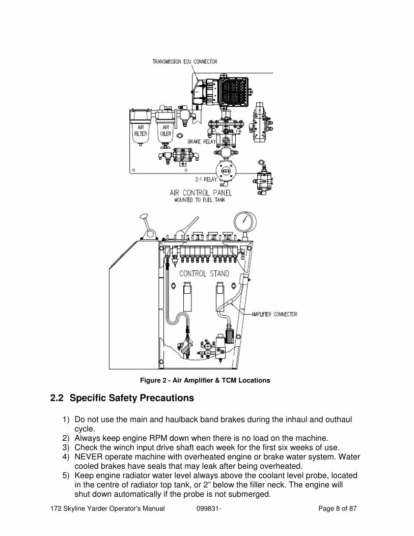
Figure 2 - Air Amplifier & TCM Locations
2.2 Specific Safety Precautions
1) Do not use the main and haulback band brakes during the inhaul and outhaul
cycle. 2) Always keep engine RPM down when there is no load on the machine. 3) Check the winch input drive shaft each week for the first six weeks of use. 4) NEVER operate machine with overheated engine or brake water system. Water
cooled brakes have seals that may leak after being overheated. 5) Keep engine radiator water level always above the coolant level probe, located
in the centre of radiator top tank, or 2” below the filler neck. The engine will shut down automatically if the probe is not submerged.
172 Skyline Yarder Operator's Manual 099831- Page 9 of 87
6) Before yarding, ensure that the guyline drum pawls are firmly engaged into the ratchet. If this is not done, an excessive load will be placed on the guyline winch drive train and a failure will result. This type of damage is not covered by repairs under warranty.
7) When raising the spar, care must be taken to avoid catching loose lines on the structure as damage will result. Once the spar is up, the cab-side pin must be installed immediately. Do not run lines on or off the drums while the spar is held only by the raising cylinder.
8) Do not weld or burn near air or hydraulic hoses. ALSO SEE NOTE 2.2.9 9) Keep all fluids up to proper level. 10) Never leave machine without first having all spring brakes and crawler brakes
engaged. 11) When the engine is running and the transmission is in gear, all gears on the
winch are turning, along with the clutches attached to them. When the transmission is in neutral and the engine is running, the gear train may still turn with the substantial torque due to transmission drag. Therefore, NEVER enter the house guards while the engine is running.
12) EXTREME CAUTION SHOULD BE TAKEN WHEN TILTing THE CAB. It can be tilted without the engine running and the crew must be aware of this. Careful observation of potential pinch points must be made at all times.
13) Do not allow the crew to stand directly under the carriage. 14) Do not climb the spar without a safety belt and fall-arresting lanyard adjusted to
proper length. 15) Operator must ensure they are aware of the brake pedal configuration setting
before operating (see Section 15 on yarding controls). The brake pedal configuration selector has a neutral position in which the brakes will not work.
16) Before each shift, clean and warm the skyline band brake by powering the drum in and out with the brake lightly applied. See skyline band brake burnishing procedure for more details. Routinely check the brake and actuator for proper adjustment.
172 Skyline Yarder Operator's Manual 099831- Page 10 of 87
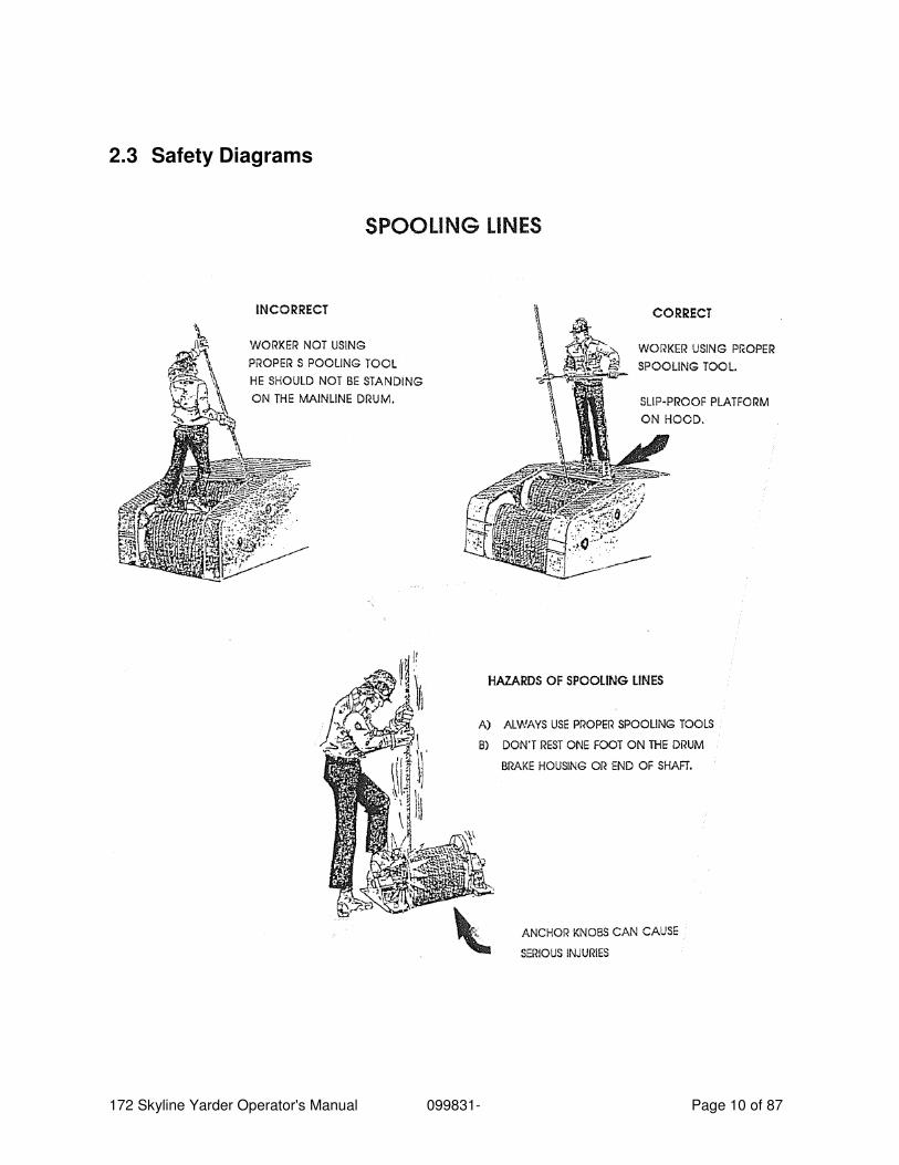
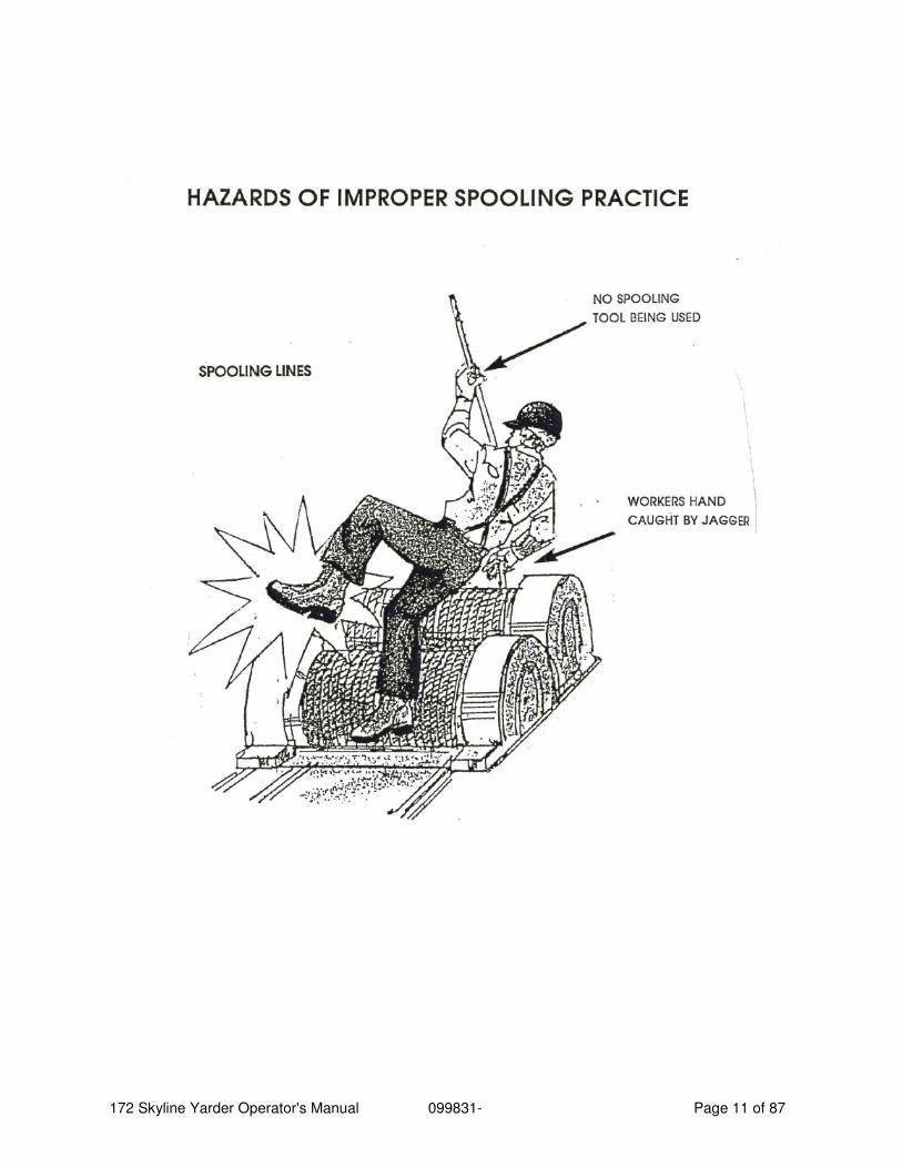
2.3 Safety Diagrams
172 Skyline Yarder Operator's Manual 099831- Page 11 of 87
172 Skyline Yarder Operator's Manual 099831- Page 12 of 87
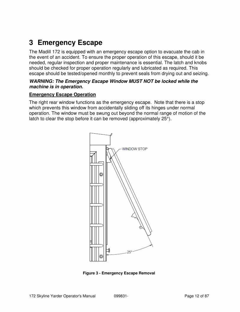
3 Emergency Escape The Madill 172 is equipped with an emergency escape option to evacuate the cab in the event of an accident. To ensure the proper operation of this escape, should it be needed, regular inspection and proper maintenance is essential. The latch and knobs should be checked for proper operation regularly and lubricated as required. This escape should be tested/opened monthly to prevent seals from drying out and seizing.
WARNING: The Emergency Escape Window MUST NOT be locked while the machine is in operation.
Emergency Escape Operation
The right rear window functions as the emergency escape. Note that there is a stop which prevents this window from accidentally sliding off its hinges under normal operation. The window must be swung out beyond the normal range of motion of the latch to clear the stop before it can be removed (approximately 25°).
Figure 3 - Emergency Escape Removal
172 Skyline Yarder Operator's Manual 099831- Page 13 of 87
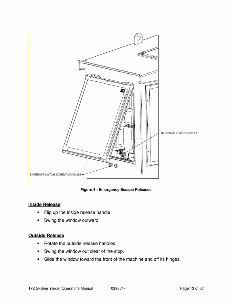
Figure 4 - Emergency Escape Releases
Inside Release
• Flip up the inside release handle.
• Swing the window outward.
Outside Release
• Rotate the outside release handles.
• Swing the window out clear of the stop.
• Slide the window toward the front of the machine and off its hinges.
172 Skyline Yarder Operator's Manual 099831- Page 14 of 87
4 General Description
4.1 Power Unit
The Madill 172 Skyline Yarder is powered by a Detroit Diesel Series 60 14.0L, 450 H.P. diesel engine. The engine is direct coupled to an Allison S5600 series power shift transmission, providing power to the yarding winch.
Start, stop and throttle controls are located in the operators cab. Start and stop functions are operated by a key switch. The throttle is electrically operated and controlled by the left joystick hand control. This control has a friction-hold device built in to maintain any selected setting. Pull back for full throttle, push forward for idle. A “neutral start” switch is incorporated in the circuitry to permit the engine to be started only when the transmission is in neutral.
4.2 Allison S5620 Transmission
The torque converter is directly coupled to the engine flywheel. An internal pump charges the converter with automatic transmission fluid from reservoir common with the transmission. The transmission has 6 forward gears, and one reverse. The transmission has been matched to select the proper converter lockup ratio, to optimize the operation of the winch speeds and pulls. This gives the operator full control of the speed and pull of the winch during inhaul and outhaul.
The electronic control unit powers up in "NEUTRAL" and all shifts are made by electronic signal to the transmission's internal valving. There is no external shift linkage. The range selected and the range attained are displayed on the keypad. The display will also show service diagnostic codes when keyed in the proper sequence. "NEUTRAL" should be selected when the rigging is stopped.
"SIXTH" (D^) is selected by pressing "D" on the keypad. Forward-range Shifts are then made by depressing either the shift “UP” or “DOWN” button on the throttle lever, backwards for downshifts and forward for upshifts, in sequence. "NEUTRAL" and "REVERSE" must be selected from the keypad. The "D 1-select" feature is activated by the keypad "mode" button. For sustained idle operation, "NEUTRAL" must be selected from the keypad for less chance of inadvertent "DRIVE" engagement.
Do not select "REVERSE" unless specifically required to unspool line. Except for the unspooling drum, all drums should have their pull clutches disengaged and brakes applied whenever “REVERSE” is selected.
When the machine is cold the transmission neutral drag may be enough that the tail shaft output speed is above the maximum allowable to shift out of neutral. If this problem occurs slow the output of the transmission by applying the winch park brake and engaging a clutch.
172 Skyline Yarder Operator's Manual 099831- Page 15 of 87
4.3 Frame
The frame is formed of a single, integral welded unit. These frames are bored on a numerical controlled machining center to provide accurately positioned shafts and to ensure parallelism. Coupling this with our precision gearing means that it is unnecessary to adjust for gear mesh resulting in a quiet, smooth running winch.
4.4 Operator’s Cab
Forward positioning of the cab provides the operator with excellent visibility while steel tube and plate construction provide safety. Simple layout and hands on controls facilitate simultaneous functions. Standard features include air conditioning and a Satellite AM/FM Radio/CD/ Bluetooth Player.
The protective guarding of the operators cab is designed and manufactured to meet the operator protection requirements of the following Workers’ compensation Board of British Columbia (Canada) Standards.
WCB Standard: G601 Log Loader and Log Yarder Backstops
WCB Standard: G602 Log Loader and Log Yarder Raised Cabs
WCB Standard: G603 Log Loader and Log Yarder Window Guards
WCB Standard: G608 Mobile Equipment Roof Structures – Heavy Duty
As well as the requirements specified by Oregon OSHA 437-007-0775
ISO 8083, ISO 8084, SAE J1356
The cab can also be hydraulically tilted to the side reducing the machine height for transport and allow access for service.
4.5 Guards
All guards serve a needed safety function; they must be replaced upon completion of any service work done on the machine, or if damaged in operation.
When the engine is running and the transmission is in gear, all gears on the winch are turning, along with the clutches attached to them. When the transmission is in neutral and the engine is running, the gear train may still turn with substantial torque due to transmission drag. Therefore, NEVER enter the house guards while the engine is running.
4.6 Handrails
Handrails must be included in regularly scheduled safety inspections. Ensure that the handrails are not broken or severely bent, paying close attention to the welds at the base of all the supports. Any handrails that are damaged should be repaired or
172 Skyline Yarder Operator's Manual 099831- Page 16 of 87
replaced immediately. Ensure that all handrails are securely fastened to the machine especially after transport.
4.7 Horn (Whistle)
The function of the horn must be tested daily and subsequently at the start of each shift. Do not operate the machine with a malfunctioning horn.
4.8 Cables (Lines)
Replace worn or damaged cables. Do not operate the machine with worn, broken, or frayed cable. Install new cables when the old ones give any indication that they may fail. Inspect cables and clamps frequently. Use only cables conforming to the requirements shown on the specification plate affixed to the yarder. Boom hoist lines and pendant straps must be replaced according to the requirements of this manual. Do not use larger running lines than are specified by the manufacturer.
Keep hands and body clear of moving cables. Never guide cables onto drums without using a proper spooling tool.
Do not allow the crew to stand directly under the carriage, whether loaded or unloaded, or in the bight of lines.
172 Skyline Yarder Operator's Manual 099831- Page 17 of 87
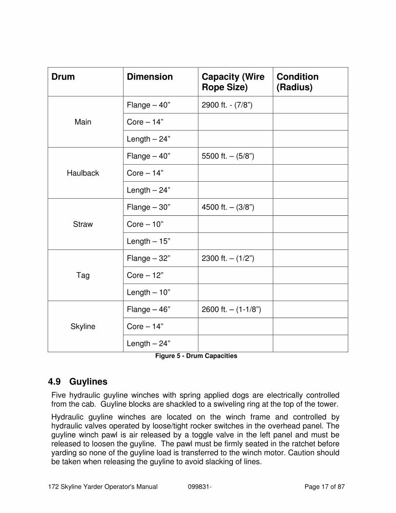
Drum Dimension Capacity (Wire Rope Size)
Condition (Radius)
Main
Flange – 40” 2900 ft. - (7/8”)
Core – 14”
Length – 24”
Haulback
Flange – 40” 5500 ft. – (5/8”)
Core – 14”
Length – 24”
Straw
Flange – 30” 4500 ft. – (3/8”)
Core – 10”
Length – 15”
Tag
Flange – 32” 2300 ft. – (1/2”)
Core – 12”
Length – 10”
Skyline
Flange – 46” 2600 ft. – (1-1/8”)
Core – 14”
Length – 24”
Figure 5 - Drum Capacities
4.9 Guylines
Five hydraulic guyline winches with spring applied dogs are electrically controlled from the cab. Guyline blocks are shackled to a swiveling ring at the top of the tower.
Hydraulic guyline winches are located on the winch frame and controlled by hydraulic valves operated by loose/tight rocker switches in the overhead panel. The guyline winch pawl is air released by a toggle valve in the left panel and must be released to loosen the guyline. The pawl must be firmly seated in the ratchet before yarding so none of the guyline load is transferred to the winch motor. Caution should be taken when releasing the guyline to avoid slacking of lines.
172 Skyline Yarder Operator's Manual 099831- Page 18 of 87
4.10 Brakes
Keep brakes and clutches properly adjusted. Adjust brakes and clutches immediately when any indication of slipping is noted. Serious injury to ground personnel or damage to property and equipment could result if adjustments are neglected. The main, slackpuller and haulback band brakes are not to be used under continuous, prolonged slipping during the inhaul and outhaul cycle. Overheating and loss of braking will result.
Do not hold the carriage or grapple stalled on the torque converter. Use the brakes.
4.11 Spar
The 72 ft. telescoping spar is fabricated steel construction with the skyline sheave 72 feet off the ground. The upper section of the spar retracts 20 feet to reduce the machine length for spar-down travelling.
4.12 Levelling Jacks
Located either side of the fuel tank, the levelling jacks are used to hold the machine level while yarding. They are operated by valves in the same bank as the guyline winch and controlled by switches in the overhead panel or by an auxiliary set of switches on the side of the guyline winch.
4.13 Spar Raising and Telescoping
These are also operated by valves in the guyline winch valve bank. Operation (by means of switches in the overhead panel) is covered under “Spar Raising and Lowering".
4.14 Spar Brace Cylinder
Tilts the spar forward to the yarding position and is operated in a similar manner to the to the two spar cylinders. This cylinder should always have 1-1/2" of extension to maintain its shock-absorbing feature.
4.15 Cab Tilt
Used to lower the cab for transport to reduce overall height. The cab tilt cylinder is actuated by the battery-powered power pack below the fuel tank, and controlled by a key switch next to the levelling jack switches on the side of the guyline winch. The hinge points are at the cab base, either side of the door. To tilt the cab down, secure alt loose items in the cab, close and latch the windows, ensure all winch parking brakes are applied, and stop the engine. Externally, secure the window guards and remove the handrail beside the cab door. Unbolt the hold-down bolts at the winch. With all personnel in the clear, activate the switch to tilt the cab. Watch that the safety strap does not catch, and beware of falling objects. Before the cab hits the fuel tank, the safety strap should come up tight.
CAUTION: This function can be performed without the engine running. To raise the cab, reverse the procedure and be alert to pinch point hazards.
172 Skyline Yarder Operator's Manual 099831- Page 19 of 87
4.16 Winch
The three major drum shafts are controlled each by a clutch and two brakes, the pulling clutch, the water-cooled brake and the band brake. With the pulling clutch applied and the transmission in forward, line will always be pulled in. Applying the clutch with the transmission in reverse will always feed out line on any of the three drum shafts. The water-cooled brakes are used to provide dynamic tension to lift or hold back the rigging while it is in motion. The band brakes are used to hold the lines when they are stopped and, with the exception of the skyline band brake, are not used for slipping.
4.17 Winch Drive
The winch is directly driven by a Spicer drive shaft which couples the transmission output shaft to the winch power input pinion shaft.
4.18 Electrical
24 volt electrical system with 8D batteries charged by a 75 Amp alternator.
4.19 Pneumatic System
One engine mounted air compressor supplying 28 cubic feet (free air) per minute.
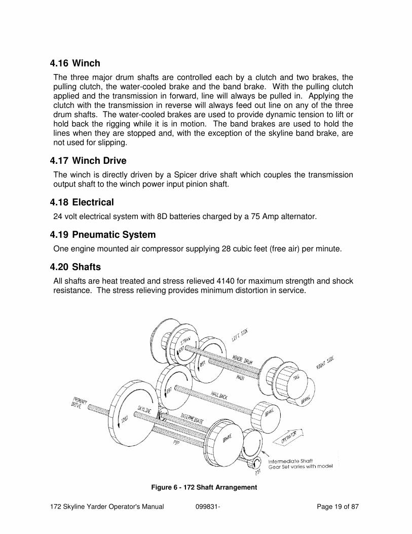
4.20 Shafts
All shafts are heat treated and stress relieved 4140 for maximum strength and shock resistance. The stress relieving provides minimum distortion in service.
Figure 6 - 172 Shaft Arrangement
172 Skyline Yarder Operator's Manual 099831- Page 20 of 87
4.21 Power Input Shaft
This shaft transmits power from the drive shaft to the winch drum shafts, increasing the torque and reducing the speed through the gear sets. NOTE: the special greasing requirements for the gear on this shaft.
4.22 Haulback Shaft
Directly in front of the spar base, it supports the haulback drum, gear, band brake, a water cooled slip brake and an air cooled pulling clutch. The haulback line runs over the top fairlead on the spar front, through a tail block and back to the yarder to pull the rigging away from the machine in the yarding operation. The line is spooled onto the drum by engaging the pulling clutch using the yarding control lever located on the right side of the operators seat. Pushing the lever handle forward engages the haulback clutch alone in the first 15° of travel. Beyond 15° handle travel, the main water-cooled brake is progressively engaged as well. The yarder is then in outhaul mode whereby the line tension generated by the clutch is maintained by the weight of the rigging and the torque of the slipping mainline water-cooled brake.
The haulback pull clutch can also be engaged, for running on line, by pushing the lever forward 15°. The haulback water-cooled brake can be actuated by the foot pedal, which is graduated to allow variable brake torque. The brake can also be gradually applied, in inhaul mode, by moving the Yarding control back past 15°. (NOTE: The main pull clutch will be also engaged at the time.)
The haulback band brake has a spring chamber for holding the rigging when the machine is shut off, with a toggle valve control on the left panel. The brake is to be used as a holding brake only.
4.23 Main Shaft
The front shaft in the drum set supports the mainline drum, gear, band brake, water cooled brake and an air cooled pulling clutch. The mainline is used for pulling in the load and is spooled onto the drum by engaging the pull clutch using the yarding control lever. Pulling the valve handle backward up to 15° engages the main pull clutch. Beyond 15° the haulback water-cooled brake is progressively engaged for tension in the inhaul direction. The mainline water cooled brake is engaged along with the haulback pull clutch in the outhaul direction by the yarding control.
The mainline band brake has a spring chamber for holding the rigging when the machine is shut off with a toggle valve control in the left panel. The water-cooled brake is controlled by the outside right foot pedal. The band brake is to be used as a holding brake only.
4.24 Skyline Shaft
The rear shaft in the drum set supports the skyline drum, gear, band brake, a water cooled brake and an air cooled pulling clutch. The skyline is used to hold up a carriage or other Ioad-carrying rigging. The main function of the skyline shaft is controlled by the hand brake hand valve and regulator in the left panel. The skyline
172 Skyline Yarder Operator's Manual 099831- Page 21 of 87
pull clutch is also engaged by the toggle valve in the left panel. The skyline water-cooled brake is progressively engaged by the left foot pedal on the floor.
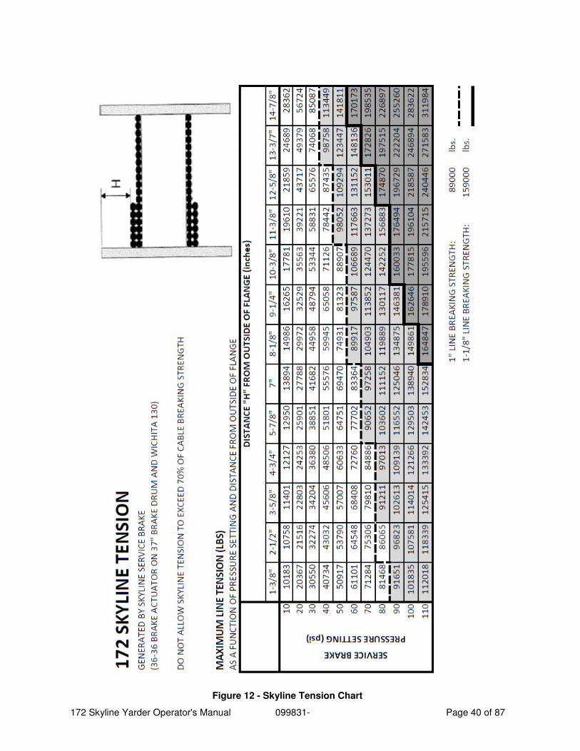
The skyline band brake has a spring chamber for holding the rigging when the machine is shut off, with a maxi toggle control in the left panel. The service chamber of the brake is controlled by the outside hand valve referred to above. The brake is to be used as a holding brake only. Prolonged slipping of the brake will result in overheating and fading. For proper setting of the brake regulator, refer to the yarding instructions and the skyline brake regulator chart ("172 Skyline Tension” Chart).
In order to provide a smoother transition from the service (band) brake to the water-cooled (pedal applied) brake when lowering the skyline, the two are operated together from the hand valve. The band predominates however, and the service brake should never be allowed to slip for more than a few turns of the drum. NEVER compound the brake by engaging the maxi and the service brake together when the skyline is loaded.
4.25 Drums
Drums are fabricated. Skyline, main, and haulback are pressed on the shafts. Straw and tag drums float on ball bearings. Five hydraulic guyline drums are provided on each machine and must be used for all yarding conditions.
4.25.1 Tagline Drum
The tagline drum is directly in front of the cab. The tagline is used to pull slack in a dropline or slackpulling carriage, to allow the dropline to be lowered to the ground while carriage is suspended by the skyline. Mounted on one end of the “minor drum shaft”, it has a water-cooled slipping clutch and a band brake with service and spring chambers. In standard yarding mode, the clutch is activated at full pressure by the button in the yarding control handle. The clutch is also activated at reduced pressure by the "drag" controls in the left panel. The "tag maxi" toggle controls the spring chamber of the brake. It is used for holding only. The service chamber is activated by a button in the yarding control handle. A regulator under the cab can be used to limit the brake torque. The third button in the control handle cuts the "tag drag" off momentarily.
4.25.2 Strawline Drum
The strawline drum assembly consists of the drum, air cooled clutch and disc brake located on the minor drum shaft. The spring brake control is located in the left panel. The graduated brake valve is located on the left side of the seat. The graduated clutch valve is located on the right side of the seat.
4.26 Gears
Helical gears are made of specially heat treated 8637 gear steel. This provides for a good grained shock resistance. They are completely machined for balance and the teeth hobbed on a precision production hobber. They are then high frequency
172 Skyline Yarder Operator's Manual 099831- Page 22 of 87
induction heat treated to provide a good wear surface and increase strength. Pinions are carburized.
This construction provides for gears which have little run out or internal variances, and makes for a smooth running gear set.
4.27 Clutches
Haulback Pulling - Madill 26 x 5
Main Pulling - Madill 26 x 5
Skyline Pulling - Madill 26 x 7
Straw - Wichita ATD 118
Tagline - Eaton 218 WCB
4.28 Brakes
Haulback Water Cooled Brake: Eaton 218
Band Brake: 30” x 4”
Main Water Cooled Brake: Eaton 218
Band Brake: 30” x 4”
Skyline Water Cooled Brake – Wichita 130H
Band Brake – 37” x 6”
Straw Disc Brake: 38-1/2” O.D.
Tagline Band Brake: 30” x 4”
Five Guylines Drum Dog
Crawler Multiple Disc, Spring Applied
4.29 Carrier Drive - Track
The 087 Carrier is driven hydraulically by the pump connected to the engine crankshaft pulley. A directional control valve for each track is located on the frame cross-member between the two final drives. The valves are proportional, providing flow metering to control travel speed. The load-sense control system provides for flow only on demand, and “load compensation” to maintain flow at each track as set by the operator, regardless of individual track operating pressure requirements. The travel motors can be shifted into high or low gear depending upon the ground condition. Two travel controls are located at the front of the cab in the center of the floor. Counter rotation of the track drive is possible by pushing one control forward and pulling back on the other.
172 Skyline Yarder Operator's Manual 099831- Page 23 of 87
5 Lexan & Marguard Windows
5.1 Replacement
It is important that damaged Lexan or Marguard windows be replaced with the equivalent product. Substitution with an inferior product may greatly reduce the level of protection to the operator and WCB requirements may not be met. For example, the impact strength of Lexan is 200 times that of glass and 30 times that of acrylic.
Protect the operator - do not substitute an inferior product!
5.2 Cleaning Instructions
When Lexan sheet is first installed, glazing compound and masking paper adhesive can be easily removed by applying naphtha (VM&P) or kerosene with a soft cloth, followed immediately with a thorough soap and water cleaning. DO NOT USE GASOLINE! Adherence to regular and proper cleaning procedures is recommended to preserve appearance.
5.3 Washing to Minimize Scratching
Wash LEXAN XL sheet and LEXAN THERMOCLEAR sheet with a mild soap or deter- gent (e.g. JOY Dishwashing Liquid) and lukewarm water, using a clean sponge or a soft cloth. Rinse well with clean water. Dry thoroughly with a chamois or moist cellulose sponge to prevent water spots. Do not scrub or use brushes on these products; their coating is UV-resistant, not mar-resistant. Fresh paint splashes, grease and smeared glazing compounds can be removed easily before drying by rubbing lightly with a good grade of VM&P naphtha or isopropyl alcohol. Afterward, a warm final wash should be made, using a mild soap or detergent solution and ending with a thorough rinsing with clean water.
5.4 Minimize Hairline Scratches
Scratches and minor abrasions can be minimized by using a mild automobile polish. Three such products that tend to polish and fill scratches are Johnson Paste Wax, Novus Plastic Polish No.1 & No.2, Novus Inc. Minneapolis, MN and Micor Glaze plastic polish (M.G.M.10), Mirror Bright Polish Co., Pasadena, CA. It is suggested that a test be made on a sample of LEXAN sheet with the product selected and that the polish manufacturer’s instructions be followed.
5.5 Some Important “Don'ts”
• DO NOT use abrasive or highly alkaline cleaners on LEXAN sheet products.
• NEVER scrape LEXAN sheet products with squeegees, razor blades or other sharp instruments.
• Benzene, gasoline, acetone or carbon tetrachloride should NEVER be used on LEXAN sheet products.
172 Skyline Yarder Operator's Manual 099831- Page 24 of 87
• DO NOT clean LEXAN sheet products in hot sun or at elevated temperatures.
• DO NOT use butyl cellosolve on XL-1 or TC-2.
5.6 Compatible Cleaners for Lexan Sheet Products
The following cleaning agents have been found compatible with LEXAN sheet, LEXAN XL sheet and LEXAN THERMOCLEAR sheet. The manufacturer’s recommendations and instructions should be followed.
• JOY
• Freib T.F.
• Palmolive Liquid
• Top Job
• VM&P grade naphtha
• Windex with Ammonia D
5.7 Marguard Sheet Cleaning Instructions
Because of this material’s highly mar-and UV resistant coating, avoid the use of abrasive cleaners and/or cleaning implements that may mar or gouge the coating.
5.8 Graffiti Removal for MARGUARD Sheet
• Butyl cellosolve works well for removal of paints, marking pen inks, lipstick, etc.
• Masking tape, adhesive tape or lint removal tools work well for lifting off old, weathered paints.
To remove labels, stickers, etc., the use of kerosene or VM&P naphtha is generally effective. When the solvent will not penetrate sticker material, apply heat (hair dryer) to soften the adhesive and promote removal. GASOLINE SHOULD NOT BE USED.
172 Skyline Yarder Operator's Manual 099831- Page 25 of 87
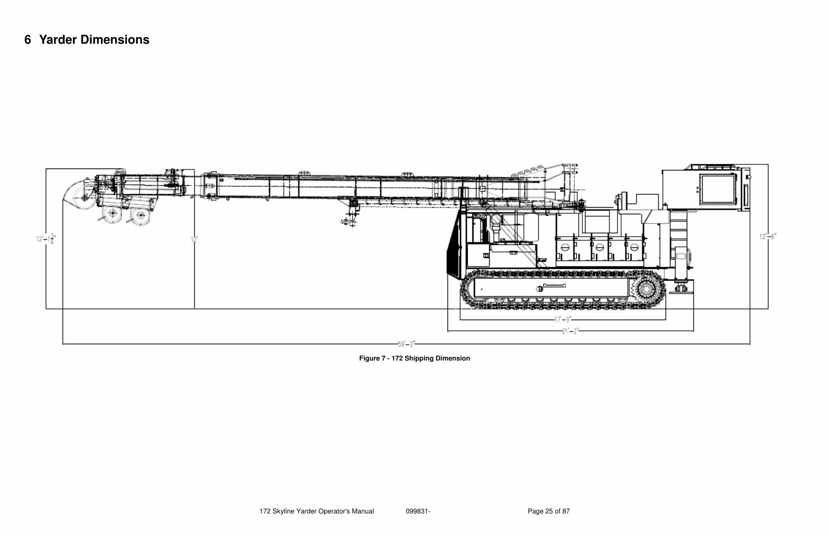
6 Yarder Dimensions
Figure 7 - 172 Shipping Dimension
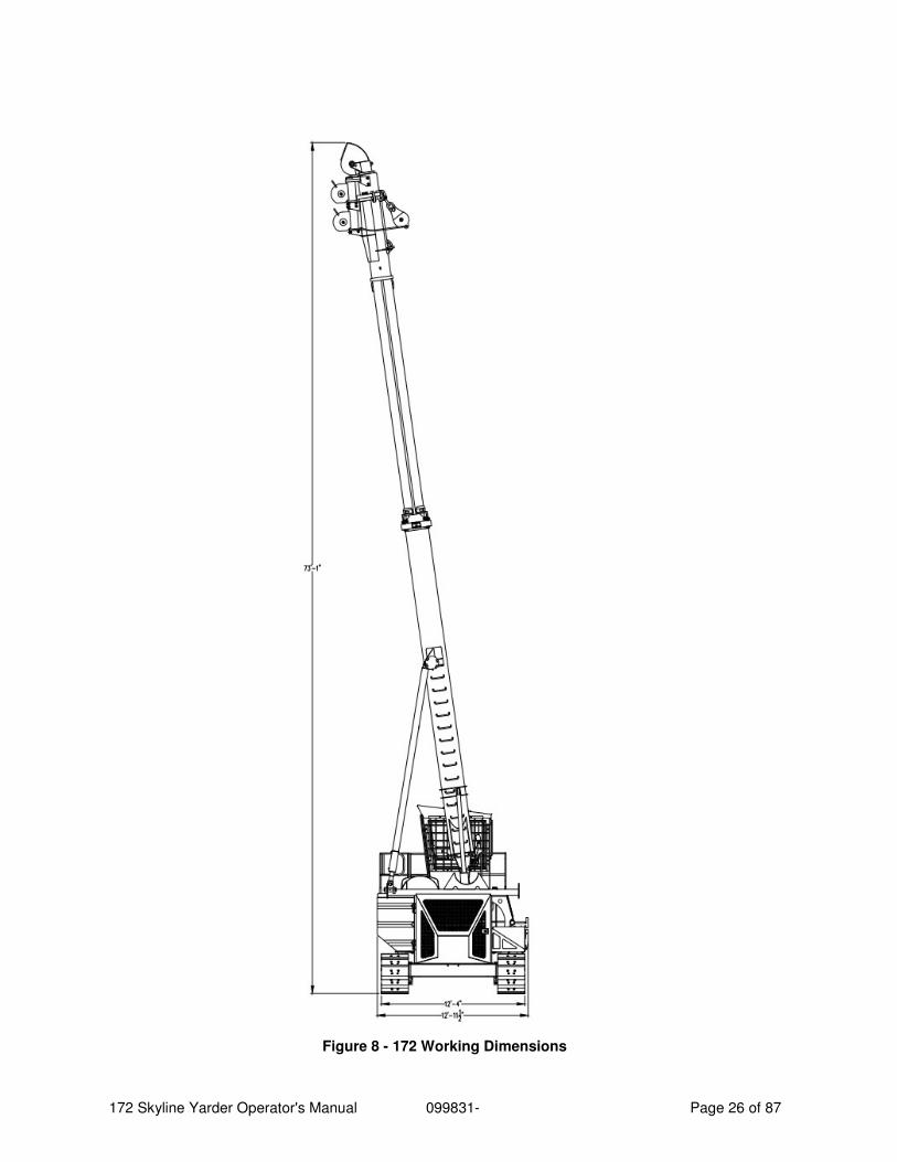
172 Skyline Yarder Operator's Manual 099831- Page 26 of 87
Figure 8 - 172 Working Dimensions
172 Skyline Yarder Operator's Manual 099831- Page 27 of 87
7 Operation
7.1 General Operation Notes
When checking for leaks in the hydraulic system, use a piece of cardboard or wood. A small stream of high pressure oil can penetrate the skin and cause serious injury. DO NOT USE YOUR HAND OR FINGERS TO SEARCH FOR LEAKS. If you are struck by pressurized hydraulic fluid, see a doctor at once.
When a machine is first delivered, it is important to go through a series of inspections and checks before placing the machine in service. Each machine has been thoroughly inspected. A comprehensive post-delivery inspection by the distributor will detect any problems developed in transit, so they may be corrected before the machine reaches its ultimate user.
Checking the positions of the shipping blocks supporting the machine can indicate what type of damage may have occurred during shipping. All blocking should be tightly in place and all cables should be properly tensioned. Loose cables and blocks mean the machine has probably been jarred and moved around, and subjected to unusual vibration. This could mean loose parts and bolts. Inspect the machine surface for damage. Walk around the machine and perform a visual inspection, checking for oil leaks.
Before the machine is run, the oil level in the engine should be checked to ensure proper level. Also check the coolant level and concentration in the radiator. Hydraulic fluid in the reservoir should be in the proper range pointed out on the sight glass; do not overfill this, room must be allowed for fluid expansion due to heat. Check the oil level in all gearboxes, add if too low, drain if over filled. Consult the lubrication instructions for correct service procedures. Lubricate all fittings to be sure they will accept grease. Re-torque bolts if necessary.
Read the procedure for machine start-up before running the engine on assembled machine.
Start and run the engine until it warms up. Cycle the various functions and examine the machine for hydraulic oil leaks.
Normally the first hours of operation are the most crucial to the machine because this is when the parts are breaking in. It is at this time that bolts loosen due to wearing-in process and metal contact is greatest in the hydraulic system. Bolts should be re-torqued at several intervals in the first 80 hours of operation.
7.2 Travel Restrictions & Precautions
1. Switch travel speed selector to low when travelling downgrades or when loading/unloading machine.
2. ** Important** re-torque the track pad bolts after their first 40 hours of operation.
3. Keep the driving sprockets to the rear while travelling.
172 Skyline Yarder Operator's Manual 099831- Page 28 of 87
7.3 Travel Brake Function
The multi-disc spring applied, hydraulically released travel brakes are automatically released when any travel control is engaged. Loss of system pressure will cause the brake to apply automatically.
7.4 Rollers & Rails
Rollers and rails, and related component life can be increased by the following preventative maintenance steps:
1. Make daily visual inspections of your equipment. Check for loose bolts, leaking seals and abnormal wear.
2. Check track tension regularly and perform a regular inspection of the rollers.
3. Consider a program of switching rollers to equalize wear. It takes time, but the dollars saved in equalizing wear usually justify the effort. The front and rear rollers take approximately 80% of the wear on track machines. The wear drops off to a minimum on center rollers.
7.5 Inspection
A proper pre-start visual inspection each day of operation will help spot problems or potential problems in their early stages and save on expensive repairs and down time. This daily inspection should be done in conjunction with any and all necessary daily lubrication requirements.
All lubrication procedures along with their locations are explained in the lubrication section of this manual.
Open the doors of the machine and look over the wiring, hoses, clamps and piping. Check the fluid levels of the engine and radiator. Check the oil level in the hydraulic oil reservoir. Inspect the side frames for oil on the rollers and the drive gear boxes. The regular inspection of this machine is the first step in a good maintenance program. Following our recommended procedures will assure you efficient and profitable operation.
172 Skyline Yarder Operator's Manual 099831- Page 29 of 87
8 Seat Controls
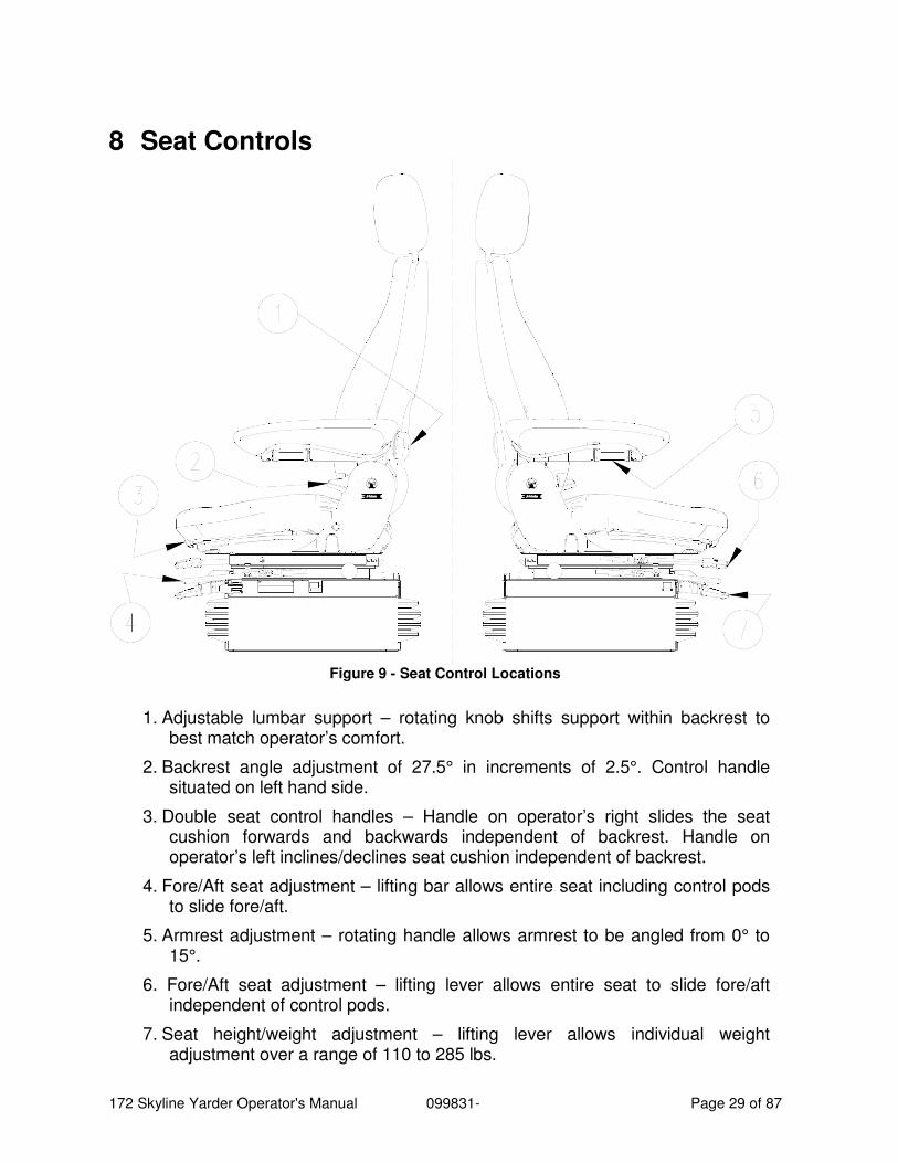
Figure 9 - Seat Control Locations
1. Adjustable lumbar support – rotating knob shifts support within backrest to best match operator’s comfort.
2. Backrest angle adjustment of 27.5° in increments of 2.5°. Control handle situated on left hand side.
3. Double seat control handles – Handle on operator’s right slides the seat cushion forwards and backwards independent of backrest. Handle on operator’s left inclines/declines seat cushion independent of backrest.
4. Fore/Aft seat adjustment – lifting bar allows entire seat including control pods to slide fore/aft.
5. Armrest adjustment – rotating handle allows armrest to be angled from 0° to 15°.
6. Fore/Aft seat adjustment – lifting lever allows entire seat to slide fore/aft independent of control pods.
7. Seat height/weight adjustment – lifting lever allows individual weight adjustment over a range of 110 to 285 lbs.
172 Skyline Yarder Operator's Manual 099831- Page 30 of 87
9 Control Panel Switches
9.1 Engine Diagnostic / Shutdown Override
Rocker switch:
Press and hold to activate diagnostic flash codes or override automatic engine shutdown.
9.2 Mode Selector
Rocker switch:
Depress UP to switch to “TRAVEL” mode, yarding winch will be deactivated.
Depress DOWN to switch to “YARD” mode, machine will not travel.
9.3 Travel Mode
Rocker switch:
Depress DOWN to lock in low speed travel.
Depress UP to allow automatic shifting between high and low.
Track drive motors have two speeds. Low speed provides high drive torque. High speed provides low drive torque.
Lock in low speed when descending grades or loading/unloading machine onto a trailer. To improve control while operating in rough terrain low speed should be engaged.
9.4 Buzzer Override
Momentary rocker switch:
Depress down to silence warning buzzer.
Buzzer will come on again only if a second warning signal is received.
9.5 Yarding Mode
Depress UP for Standard
Depress DOWN for Gravity (Shotgun)
When in “Gravity Mode”, the skyline clutch can be operated by pressing the “Tag Clutch” button in the yarder control handle. (In "gravity” mode, the tagline night brake should be on at all times.)
9.6 Levelling – Left Jack
Rocker switch:
Depress UP to raise jack (retract)
Depress DOWN to lower jack (extend)
172 Skyline Yarder Operator's Manual 099831- Page 31 of 87
9.7 Levelling – Right Jack
Rocker switch:
Depress UP to raise jack (retract)
Depress DOWN to lower jack (extend)
9.8 Guyline Winch – All Drums
Dual position rocker switches are located in the overhead control pod. To use the guyline and winch drums the dogs must be released using the toggle valves in the control stand. Operate one drum at a time, checking that line is correctly spooled, correct mis-spooled line immediately.
Rocker switch:
Depress UP for line in (tighten)
Depress DOWN for line out (slack)
9.9 Ignition
3 position key switch:
OFF - Shuts off all electrical power via relay operated battery switch
ON - Switches on electrical power
START - Energizes engine starter solenoid, warning light bulb test circuit and warning buzzer.
9.10 Heater - A/C
Turn AC knob to switch the AC System ON or OFF.
Turn the temperature knob to adjust temperature.
Turn fan knob to desired location to control fan speed.
9.11 Wiper
Rotary switch: 2 speed
Separate switches control upper & lower wipers
9.12 Diagnostic Plug
A plug is provided for connection of engine diagnostic equipment
It is located at the back of the control panel.
9.13 Circuit Breakers
Circuit breakers provide individual protection to electric circuits. Overloading will cause circuit breaker to trip and the button to pop out.
To reset, push button in.
172 Skyline Yarder Operator's Manual 099831- Page 32 of 87
9.14 Dome Light
Aircraft style dome light is controlled by a switch incorporated into the light.
9.15 Defroster Fan
Swiveling fan controlled by switch on fan.
10 Control Panel Indicators
10.1 Brake Water Temperature Light
Illuminates when water temperature reaches 190°F (88°C), sustained operation above this temperature may result in slip-clutch seal damage.
10.2 Brake Water Pressure Light
Indicates low water pressure in the slip-clutch (regen) cooling water circuit. At or near idle this light may illuminate, depending on the pressure setting. Check the system in the light fails to go out once throttle is applied.
10.3 Check Transmission Light
Indicates that the Allison Electronic Control Module has detected an error condition in the transmission, and transmission function may be affected. Refer to the Allison Operators manual for further information.
10.4 Check Engine Light (Yellow)
Indicates an engine problem that will not cause immediate catastrophic failure, but that must be diagnosed and attended to at the earliest opportunity.
10.5 Stop Engine Light (Red)
Indicates an engine problem that may cause failure. Stop the engine and diagnose immediately. See the Detroit Diesel “Engine Operators Guide” for more detail.
10.6 Low Hydraulic Oil Level Light
Indicates that the oil level in the tank is below the level of the sight glass, top up the tank.
10.7 Hydraulic Oil Temperature Light
Indicates that the hydraulic tank temperature is high, continued operation at high temperatures may result in component damage and loss of steering control.
10.8 Low Fuel Light
Indicates low fuel level in the tank, refuel immediately to prevent fuel pump starvation and loss of prime.
172 Skyline Yarder Operator's Manual 099831- Page 33 of 87
10.9 Air Pressure Gauge
Displays the air pressure in the system reservoir, Do not operate the yarder controls until the gauge shows 120 psi.
10.10 Hourmeter
Displays accumulated machine hours, record and use for maintenance.
10.11 Water Temperature
Engine water temperature reading.
10.12 Engine Oil Pressure
Engine oil pressure reading.
10.13 Voltmeter
Shows charging voltage produced by the alternator, normally 27.5v although a range of 24-30v is acceptable.
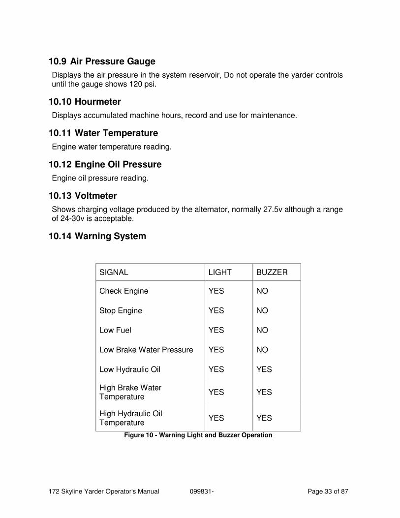
10.14 Warning System
SIGNAL LIGHT BUZZER
Check Engine YES NO
Stop Engine YES NO
Low Fuel YES NO
Low Brake Water Pressure YES NO
Low Hydraulic Oil YES YES
High Brake Water Temperature
YES YES
High Hydraulic Oil Temperature
YES YES
Figure 10 - Warning Light and Buzzer Operation

172 Skyline Yarder Operator's Manual 099831- Page 34 of 87
11 Additional Cab Controls
11.1 Travel-Left & Right Pedals
To maximize undercarriage component life keep the drive sprockets to the rear of the machine. This orientation is assumed for travel direction descriptions.
FORWARD Depress front of both pedals
REVERSE Depress rear for both pedals
STEER LEFT Depress front of right pedal and rear of left pedal to steer left
STEER RIGHT Depress front of left pedal and rear of right pedal to steer right
11.2 Guyline Dogs
Toggle valves are used for the guyline dogs.
NOTE: Always visually check the guyline and winches to confirm that the dogs are properly seated before beginning the yarding operation.
11.3 “All Pull” Button
The all pull button located in the handle of the yarding control applies the main and haulback clutches simultaneously.
11.4 Parking Brake
The parking brake toggle located in the control stand applies all drum service brakes simultaneously. This includes: skyline, haulback, mainline, strawline, and tagline night brakes. This switch must be off while yarding.
11.5 Brake Pedal Configuration Selector
A selector valve located under the cab can be used to change the configuration of the brake pedals. The operator must always ensure they are aware of the configuration before operating the machine,
In position "A" (valve handle pulled away from valve body) the haulback brake is on the left pedal and the skyline brake is on the inner right pedal. The mainline brake is on the outside right.
In position "B", (valve handle pushed toward valve body) the skyline brake is on the left and the haulback brake is on the inner right. The mainline brake remains on the outside right.
NOTE: The selector valve has a neutral position. In this neutral position THE HAULBACK AND SKYLINE BRAKES WILL NOT OPERATE.
172 Skyline Yarder Operator's Manual 099831- Page 35 of 87
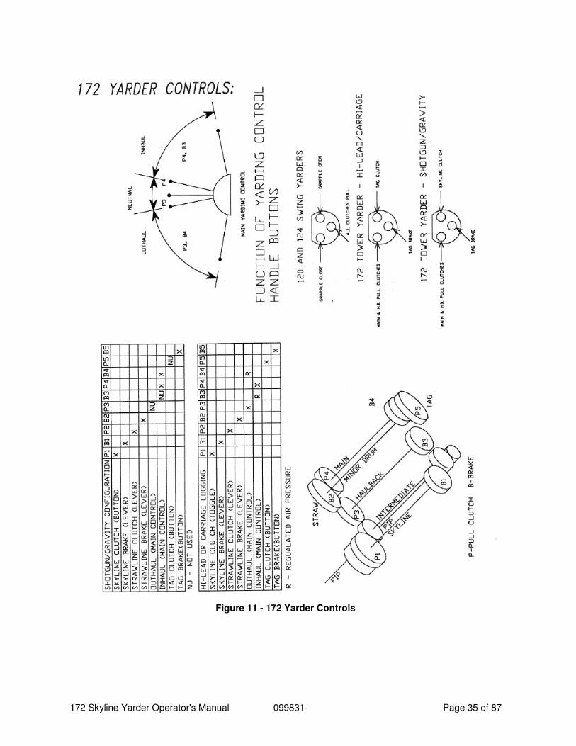
Figure 11 - 172 Yarder Controls
172 Skyline Yarder Operator's Manual 099831- Page 36 of 87
11.6 Skyline Maxi
The skyline night brake (maxi) is controlled (“on” or “off”) by a toggle switch located in the left control panel. Switching to “on” exhausts the air in the spring chamber of the actuator and applies the night brake. This brake is only to be used to hold up the skyline at night when the air pressure is 0 psi. The skyline night brake switch is to remain in the “off” position at all times during skyline yarding.
11.7 Skyline Service Brake
The skyline service brake is used to hold up the skyline when yarding. The skyline service brake control, a hand valve, is located in the left control panel. The skyline service brake air pressure must be regulated based on the line size, actuator size, and amount of line remaining on the drum. The regulator is located in the left control panel.
To set the skyline brake pressure, check the actuator and line size, and when the line is run out to the tailhold, check the amount of line left on the drum. With no load on the brake, pull the hand valve towards the seat to pressurize the brake. Adjust the regulator until the air pressure reaches the desired setting. This pressure setting will allow the brake to slip before the skyline becomes overloaded.
NOTE: The skyline service brake (hand valve) is a band brake, which is not particularly suitable for continued slipping. Reduce tension and control slipping using the pedal actuated water cooled brake on its own.
11.8 Skyline Water Cooled Brake
The skyline water cooled brake is used when lowering the skyline, and when pulling out the skyline to the tail hold when rigging up. A foot pedal (left of three or middle of three) located on the floor of the cab in front of the operator actuates the brake. The skyline water cooled brake is used mainly in conjunction with the skyline service brake when lowering the skyline. With skyline tension set on service brake, apply water cooled brake, slowly release service brake, then release water cooled brake until desired tension on the skyline is achieve. Always operate in this order to prevent unnecessary slipping of the service brake.
11.9 Skyline Clutch
The skyline clutch is controlled by a toggle switch on the panel to the left of the operator. To engage the clutch, move the switch toward the seat. The valve is either open or closed, so there is no ability to slip the clutch. The drum speed must be controlled using the engine throttle, or by applying the water cooled brake.
11.10 Haulback Maxi
The haulback night brake (maxi) is controlled (“on” or “off”) by a toggle switch located in the left control panel. When yarding, the toggle switch must be pulled toward the center of the cab to release the night brake at all times. The only exception is when the yarding method (i.e. shotgun) does not use the haulback line.
172 Skyline Yarder Operator's Manual 099831- Page 37 of 87
The night brake must be used only as a parking brake to hold the line when the machine is stopped.
11.11 Haulback Water Cooled Brake
The haulback service brake is a water cooled brake. It is used to hold back the carriage when on a downhill outhaul. There are two controls for this brake, the yarding control on the right side of the seat, and the middle foot pedal on the floor in front of the operator. The haulback brake air pressure will be indicated by the gauge in the left panel. This gauge will read the higher of the main or haulback water cooled brake pressures.
When using the haulback (and main) water cooled brake, the water pressure and the temperature must be checked frequently. Warning lights for these are located in the overhead panel. Water pressure will increase as engine speed increases. Water temperature should not exceed 180°F. Should the light come on, the machine should be run with the water cooled brakes released to circulate and cool the water. The pressure light may come on at low engine speed, but normally go out just above idle.
11.12 Haulback Clutch
The haulback clutch is controlled by a micro switch in the yarding control on the right hand side of the seat. To engage the clutch, move the lever ahead 15° to trip the switch and actuate the valve. The valve is either open or closed, so there is no ability to slip the clutch. The drum speed must be controlled using the engine throttle, or by applying the water cooled brake. Movement of the lever past 15°sends a graduated signal to a proportional valve that actuates the mainline water cooled brake. Outhaul tension can thus be controlled by a single lever.
11.13 Mainline Maxi
The mainline night brake (maxi) is controlled (“on” or “off”) by a toggle switch located in the left control panel. Pushing the toggle toward the window applies the night brake. When yarding, the toggle switch must be pulled toward the center of the cab to release the night brake. The night brake must be used only as a parking brake to hold the line when the machine is stopped.
11.14 Mainline Water Cooled Brake
The mainline service brake is a water cooled brake. It is used to hold back the carriage when on a downhill outhaul similar to the haulback. There are two controls for this brake, the foot pedal all the way to the right, and also by moving the yarding control lever back past 15°. In addition, the main and haulback service brakes can be applied together at full pressure by means of the rearmost toggle valve in the left panel. This should only be done once the drums have been brought to a complete stop using the water cooled brakes.
172 Skyline Yarder Operator's Manual 099831- Page 38 of 87
11.15 Mainline Clutch
The mainline clutch is controlled in a similar manner as the haulback clutch. To engage the clutch, move the lever back 15° to trip the switch and actuate the valve. The valve is either open or closed, so there is no ability to slip the clutch. Movement of the lever past 15°sends a graduated signal to a proportional valve that actuates the haulback water cooled brake. Inhaul tension can thus be controlled by a single lever.
11.16 Strawline Brakes
The Strawline night brake and service brake controls operate the disc brake caliper. The night brake is controlled ("on" or "off") by a toggle valve in the left panel. Push toggle toward the window to apply the brake. The night brake is used to hold the straw drum whenever the strawline is not being used. To release the brake (when air pressure is high enough) pull the toggle toward the center of the cab.
The strawline service brake is controlled by a hand valve located in the right side seat pod which allows the air pressure at the brake to be varied for slipping purposes. The air pressure will show on the gauge on the valve mounting plate. Zero pressure means the service brake is released.
11.17 Strawline clutch
The strawline clutch control is a graduated hand valve located on the left side seat pod. This allows for variable air pressure at the clutch for slipping purposes. The air pressure at the clutch will show on the gauge on the valve mounting plate. Pull the valve handle toward the operator's seat to engage the clutch. Do not slip the clutch too much or it will overheat.
11.18 Tagline Brake
The tagline brake is operated in 2 ways. There is a night brake (“on” or “off”) toggle in the left panel. There is also a “Tag Brake” button in the handle of the yarding control that engages and disengages the brake. This button is connected through a latching relay, allowing the brake to be applied without holding the button. Briefly pressing the tag button will apply the tag brake. To release the tag brake, briefly press the tag brake button a second time. This machine is also equipped with a graduated hand valve tag brake control. This is located at the rear of the control stand.
11.19 Tagline Clutch
The tagline clutch is controlled by the “Tag Clutch” button in the handle of the yarding control.
11.20 Tagline “Drag In”
The "tag drag in" is controlled by a (“on” or “off”) toggle in the left panel. When on, regulated air is supplied to the tagline clutch. It will only do this when the main clutch is engaged. The "tag drag in" control is used to pick up slack in the tag line when
172 Skyline Yarder Operator's Manual 099831- Page 39 of 87
the carriage is pulled in by the mainline. A light pressure on the tagline clutch causes the drum to turn and pick up the slack without constant attention to the controls. The air pressure regulator is located next to the "tag drag out" in the top section of the control stand and should be set for 8-12 psi indicated on the gauge attached to the regulator.
11.21 Tagline “Drag Out”
The "tag drag out" is controlled by a (“on” or “off”) toggle in the left panel. When on, regulated air is supplied to the tagline water-cooled clutch. It will only do this when the haulback clutch is engaged. The "tag drag out" control is used to keep tension in the tagline and prevent the drum from over spooling when the tagline is pulled out by the haulback (as done in carriage logging). The air pressure regulator is located in the top section of the control stand and should be set for 6-10 psi, indicated on the gauge attached to the regulator.
172 Skyline Yarder Operator's Manual 099831- Page 40 of 87
Figure 12 - Skyline Tension Chart
172 Skyline Yarder Operator's Manual 099831- Page 41 of 87
12 Yarder Operation
12.1 Engine Start-up
• Before starting engine, check entire machine to be sure all is in proper working order and all workers are clear of moving parts.
• Check oil level in engine, transmission, and hydraulic tank as well as water level in brake end engine cooling system. Transmission oil level can be checked using the OLS sensor on shift selector.
• Ensure fuel line valve is open.
• Turn the key to the “accessory” or “ignition” position. This will energize the battery relay and connect the electrical system to the batteries. The panel indicator lights will light up.
• Check that the transmission neutral indicator comes on in the shift keypad. (The cab control for the transmission is located in the left panel.)
• Refer to the engine manual for details on starting (see parts manual). Crank the engine over using the key switch.
• Allow air pressure to build up to 120 PSI before operating the winch.
• For cold weather, starting aids may be required. See parts manual.
• Avoid cranking engine more than 30 seconds at one time.
• Check hydraulic system level indicator, transmission oil indicator and engine gauges.
12.2 Self-Propelled Travelling
• Walk around the machine to check for proper track tension. Look for, and remove, obstructions in the tracks and around the crawler. Observe the orientation of the drive sprockets relative to the intended direction.
• Check that the transmission is in neutral.
• Ensure that the crawler brakes are on (both travel control valves in the neutral position).
• Set mode selector switch to “Travel”.
• Ensure that all working lines and guylines are in with the loose end hooked to the machine. For short moves on level ground (provided there is overhead clearance) the yarder can be moved with the tower up IF it is upright (vertical) and the tower top is retracted.
• Using the lever on the left side of the seat, set the throttle to the desired level. (This may be just off idle for inching on level ground, or near full engine speed for road travel.)
• Steer using the steering control valves. These valves are a pair of floor mounted lever / pedal actuated controls directly in front of the operator’s seat.
172 Skyline Yarder Operator's Manual 099831- Page 42 of 87
The track motors will automatically switch from “High Speed Travel” to “Low Speed Travel” as the grade increases and more torque is required to keep the machine moving. For safety on grades and low speed inching the track motors can be held in “Low Speed Travel” using the Travel High/Low switch mounted in the control panel.
CAUTION: Ensure that the travel control valves are in the neutral position before leaving the cab; this allows the crawler brakes to automatically engage. If the machine is to be parked switch into “Yarding” mode.
12.3 General Travel Recommendations
• Travel with the spar down, lines pulled in with their free ends hooked to the machine, level jacks retracted.
• Where stability is a concern (steep hills, severe cross-road slope), travel only with the spar down, in “low”. For steep downhill travel, reverse down the hill with the spar lowered and pointing uphill. ( A spotter is recommended for this type of move)
• For extended moves, tie the lines and rigging close to the machine rather than have it hanging from the fairleads.
CAUTION: Be alert for overhead hazards such as tree limbs, rock bluffs and, especially power lines.
Do not attempt to tow along the road any rigging that is attached to the tower.
172 Skyline Yarder Operator's Manual 099831- Page 43 of 87
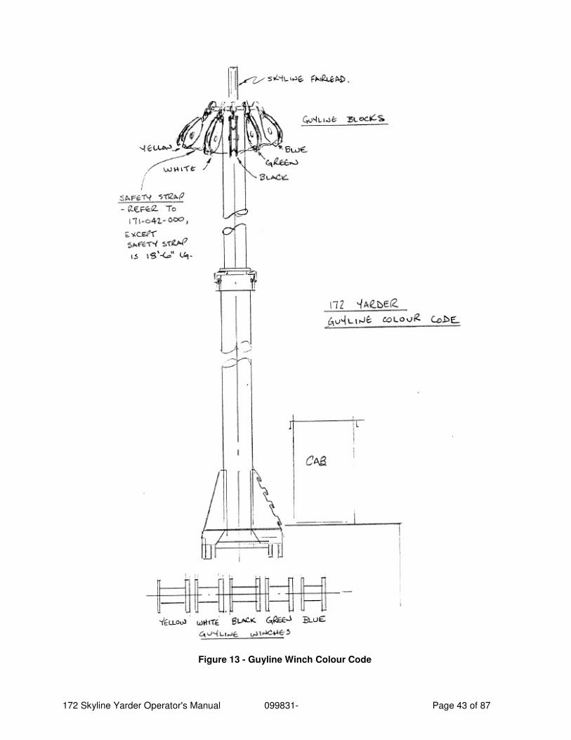
Figure 13 - Guyline Winch Colour Code
172 Skyline Yarder Operator's Manual 099831- Page 44 of 87
12.4 Guyline Operation
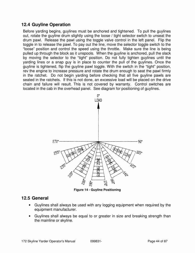
Before yarding begins, guylines must be anchored and tightened. To pull the guylines out, rotate the guyline drum slightly using the loose / tight selector switch to unseat the drum pawl. Release the pawl using the toggle valve control in the left panel. Flip the toggle in to release the pawl. To pay out the line, move the selector toggle switch to the “loose” position and control the speed using the throttle. Make sure the line is being pulled up through the block as it unspools. When the guyline is anchored, pull the slack by moving the selector to the “tight” position. Do not fully tighten guylines until the yarding lines or a snap guy is in place to counter the pull of the guylines. Once the guyline is tightened, flip the guyline pawl toggle. With the switch in the “tight” position, rev the engine to increase pressure and rotate the drum enough to seat the pawl firmly in the ratchet. Do not begin yarding before checking that all five guyline pawls are seated in the ratchets. If this is not done, an excessive load will be placed on the drive chain and failure will result. This is not covered by warranty. Control switches are located in the cab in the overhead panel. See diagram for positioning of guylines.
Figure 14 - Guyline Positioning
12.5 General
• Guylines shall always be used with any logging equipment when required by the equipment manufacturer.
• Guylines shall always be equal to or greater in size and breaking strength than the mainline or skyline.
172 Skyline Yarder Operator's Manual 099831- Page 45 of 87
• No attachments or auxiliary equipment should be affixed to any guyline or the machine.
• Ratchets on guyline drums must be firmly set, reverse drum to engage pawl before starting to yard in logs.
• On machines with more than one guyline, the load must always be shared equally by at least two guylines.
• Inspect guylines closely before yarding, damaged lines should be replaced before yarding commences.
• Guylines should be made of plow steel or better material.
• Splicing of guylines is not recommended.
• Extensions and connections must be of equal or greater breaking strength than the guyline.
• Always try to rig guylines as shown in the diagrams, keeping lines inside the shaded areas.
• Tighten or loosen guylines only with the guyline winch motor. Do not tighten by walking the machine away from stumps. Also do not pull lines off drum by walking the machine, as this will damage the winches and make them unsafe for yarding.
Never operate the yarder with a missing or damaged guyline safety strap.
• Guylines should not be fully tightened until the yarding lines or a snap guy is in place to counter the pull of the guylines.
172 Skyline Yarder Operator's Manual 099831- Page 46 of 87
13 Installing Lines With the spar down, hang the guyline blocks. For 5 guyline winches the order is blue on the top, then green, then black, then white, and then yellow on the bottom.
String guylines through blocks one at a time (blue, green, black, white, yellow) pushing through the block toward the spar. Tie the five lines to the winch frame with enough extra length to install a ferrule at drum anchors. Before attaching ferrule, raise the spar, check for twists and crossovers and then anchor the line to its corresponding winch with ferrule. Spool the line in until approximately 8 feet off the ground. Repeat with the next guyline.
Lower the spar and hook the eyes of the guylines to the hooks on the spar. Pull the guylines snug, making sure they lay over the posts above the guyline winches. When raising and lowering the spar, leave plenty of slack in the guylines.
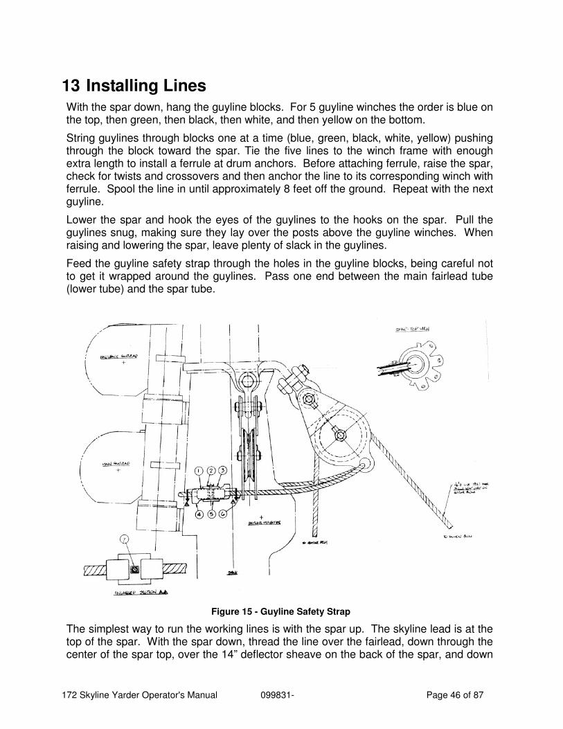
Feed the guyline safety strap through the holes in the guyline blocks, being careful not to get it wrapped around the guylines. Pass one end between the main fairlead tube (lower tube) and the spar tube.
Figure 15 - Guyline Safety Strap
The simplest way to run the working lines is with the spar up. The skyline lead is at the top of the spar. With the spar down, thread the line over the fairlead, down through the center of the spar top, over the 14” deflector sheave on the back of the spar, and down
172 Skyline Yarder Operator's Manual 099831- Page 47 of 87
to the drum. Install the correct size (1-1/8”) ferrule (knob) on the end of the line. Insert the line, knob end first, into the hole in the drum core. Turn the line end so that the line rests in the slot leading out onto the outside of the core. Pull back on the line to firmly seat the knob shoulder against the bearing plate.
The haulback is the upper of the two fairleads on the front of the spar, the lower is the main. With the spar down, thread these two lines over the fairleads, and down through the tubes to the drums. Install the knobs on the lines onto their drum cores as was done with the skyline.
The tagline fairlead is on the cab side of the spar and the strawline is on the raising cylinder side. Pass these lines through the ferrules in the drum cores and install the wedges. Pull back on the lines to seat the wedges. These two drums are under-spooled.
Once all of the lines have been threaded, the spar can be raised. And lines spooled on following local Workers Compensation / OSHA safety rules and the manufacturers recommendation. Always use a line spooling tool.
For maximum allowable line sizes and minimum guyline diameters, see the Machine Specification Plate fastened to the cab.
172 Skyline Yarder Operator's Manual 099831- Page 48 of 87
14 Raising and Tilting Spar These instructions are for guidance only. Use common sense and react to the situation that exists. Make sure the area around the raising cylinder is clear and nothing obstructs movement of the cylinder or spar.
Raising and lowering of the spar should be done with the winch transmission in neutral except when necessary to pay out or spool in line. Guyline winches are hydraulic and will operate with the transmission in neutral.
All crew should stand well clear of the spar during raising and lowering. If it is necessary to re-adjust lines or rigging, it should be done from a secure footing away from the spar and clear of potential pinch points.
14.1 Raising the Spar
• Check that the hinges are lubricated, and the pins are secure. Check the condition of hydraulic hoses and fittings.
• Check winch lines to see that they are slack and free to move as the spar comes up. Make sure there are no loose objects that could fall off of the spar as it is raised.
• Follow the starting instructions and start the engine from the yarder cab.
• Pressurize the brace cylinder to hold it in extending position.
• Extend the raising cylinder slowly, watching lines to ensure they don’t bind.
• When the spar reaches the vertical position, the spar hinge lug will line up with the saddle on the winch frame next to the cab. The pin must now be inserted and secured with the collar, retainer bolt, and nut. Do not proceed until this pin is in place. It may be necessary to lift the spar slightly to line the pin up. Never put your fingers in the bore to check alignment.
• With the spar pinned in the vertical position, extend the telescoping spar top, and lock it in position.
• Pull guylines out and anchor.
• Retract the brace cylinder to approximately 1-1/2” from end of stroke, so spar is at 7°-8° yarding angle and the weight is taken by the guylines. Adjust guylines and reset pawls as necessary. Run out working lines and rigging.
NOTE: some machines (at owners request) have been equipped with a bypass valve to allow the brace cylinder to float during yarding operation. ALWAYS close this valve while adjusting the spar position.
14.2 Lowering the Spar
• Check that the hinges are lubricated, and the pins are secure.
• Check the condition of hydraulic hoses and fittings.
172 Skyline Yarder Operator's Manual 099831- Page 49 of 87
• Pull in the rigging and working lines. Remove carriage, if used. Leave lines slack on the ground. Loosen guylines. If the telescoping spar is extended, carry out steps 4 & 5.
• Extend brace cylinder to tip spar up to vertical position.
• Retract the upper spar section.
• Extent raising cylinder briefly to make sure the base is filled and all of the plumbing functional.
• With all lines pulled in and slack on the ground next to the machine, and with the raising cylinder ready to take the load, remove the hinge pin located next to the cab.
• Lower the spar slowly by retracting the raising cylinder, while making sure that the lines do not foul and that the spar engages properly with the saddle.
14.3 Extending Telescoping Spar
• Raise and pin the spar as outlined above.
• Yarding lines should be tied to the carriage, or some other weight on the ground. Guylines should be anchored and left slack. Close the bypass valve at the base of the telescoping cylinder.
• Actuate the extending cylinder to push the spar out approximately 6”.
• Release the spar locks using the switch in the overhead panel.
• Actuate the telescoping cylinder to slowly extend the spar. Check that all lines are moving freely over their sheaves. If the guylines tighten, they will need to be powered out. Extend the cylinder to its maximum stroke.
• Check that the stop collar is clear of the locks, then engage the locks. Visually check that all 4 locks are engaged.
• Allow the spar upper section to come down far enough to seat the stop collar on the spar locks.
• Open the bypass valve to allow the telescoping cylinder to retract under its own weight.
14.4 Retracting Telescoping Spar
• Lines should be hooked up, but slightly slack. Spar to be in the vertical position. Close the telescoping cylinder bypass valve.
• Actuate the telescoping cylinder to extend the spar and lift the stop collar clear of the spar locks. Release the spar locks.
• Visually check that all 4 locks have released enough to allow the stop collar to pass.
• Allow the upper section to retract under its own weight, holding back with the telescoping cylinder and controlling the speed with the hydraulic valve.
172 Skyline Yarder Operator's Manual 099831- Page 50 of 87
• Pick up slack in the lines by powering the drums to prevent “bird nesting”.
• Before the spar is fully retracted, engage the spar locks so the spar is resting, when fully retracted, on the locks.
NOTE: The bypass valve on the telescoping cylinder allows hydraulic oil to pass back to the tank, allowing the cylinder to fall under its own weight when not in use, which will prolong the cylinder life. It must not be opened when the cylinder is supporting the weight of the spar.
172 Skyline Yarder Operator's Manual 099831- Page 51 of 87
15 Yarding Operation
15.1 Preparation For Yarding Rig Up
1. Line up the machine with the yarding road so that the track rollers are level with each other and the track sprockets are level with or lower than the idlers. Extend the levelling jacks. (Extend cylinders only as much as is required to level machine.)
2. Raise spar following "Raising and Tilting" instructions.
3. The guylines should be rigged as shown on the diagram "Guyline Placement" following also the instructions under "Installing Lines" and local WCB/OSHA regulations.
4. When tightening the powered guylines pull only until weight of spar is taken up by all five guylines equally. Any more will only tip the machine.
5. Guyline Drum Operation - IMPORTANT NOTE: Each drum dog must be firmly seated in its ratchet before yarding commences. If this is not done, an excessive load will be placed on the drive chain and hydraulic motor resulting in failure. THIS TYPE OF BREAK IS NOT COVERED BY REPAIRS UNDER WARRANTY.
6. Follow local Compensation Board/OSHA rules for attaching guylines to stumps.
7. CAUTION: Yarding beyond 30° either side of “fairlead” (in line with centerline of winch frame) may cause excessive loads on the spar hinge and crawler drive gears.
15.2 Rig Up
1. The yarding method will be selected to match the site conditions and equipment available. See the descriptions on the pages following.
2. The working lines and guylines are generally pulled out from the yarder with the lighter "strawline" or “haywire". This line is pulled off its drum by hand, out to a tailblock or utility block anchored to a stump, and back to the machine. Alternatively, the strawline may be assembled by hooking together the ends of short sections strung out end-to-end manually along a line from the yarder to the tailhold. Once the extreme end of the strawline is back at the machine, it is connected to a guyline or working line and that line is pulled to its anchor point by engaging the strawline clutch and releasing the brake to wind the strawline onto its drum. Always set the guylines out first.
3. When spooling strawline, keep the clutch air pressure low to avoid damaging the line. Apply the brake slightly to keep the drum from free-wheeling. Select a lower gear and keep the engine speed down. Do not allow the drum to become too full, the wedging action of the hooks and eyes can exert extreme pressure on the drum flanges. It may be necessary to stop occasionally, tie the bush-end of the line to the machine, unhook the connection and peel a couple of sections off the drum before re-hooking and proceeding.
4. When rig-up is complete, tie the strawline end to the yarder, set the maxi and release the clutch and service brake.
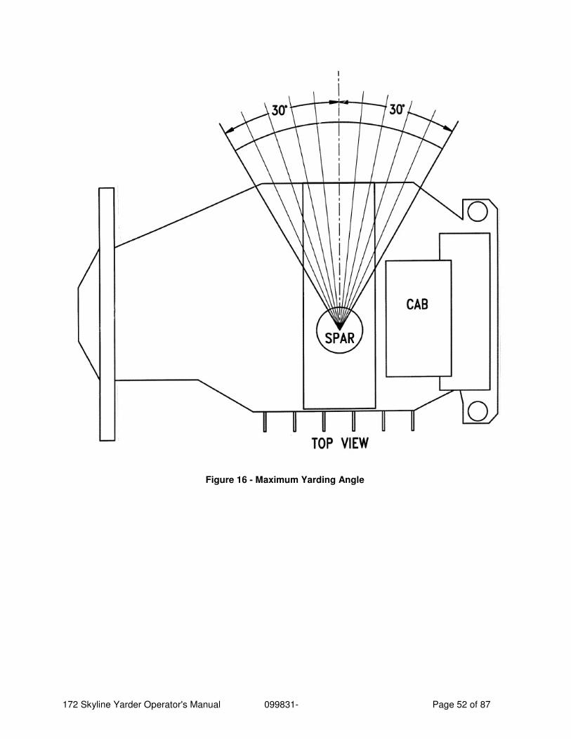
172 Skyline Yarder Operator's Manual 099831- Page 52 of 87
Figure 16 - Maximum Yarding Angle
172 Skyline Yarder Operator's Manual 099831- Page 53 of 87
16 Yarding Methods
16.1 Highlead Yarding
1. Feed the strawline through the tailblock by hand and hook to the haulback line through the tailblock and attach it to the rear of the butt rigging. Attach the mainline to the front of the butt rigging.
2. Tighten the lines by applying the main drum service (water cooled) brake and taking in line on the haulback drum. (Release the haulback brakes and engage the haulback clutch by pushing the yarding control lever ahead 15 degrees.)
3. As soon as the lines are tight increase RPM to accelerate the rigging to the fallen trees. (Adjust air pressure on the main drum brake using foot pedal or hand valve to maintain desired line tension. The yarding control handle, when pushed ahead past 15° will gradually Increase actuation pressure to the main drum water-cooled brake and can be used instead of the foot pedal on outhaul.)
4. When the rigging reaches the desired location reduce throttle and apply main and haulback brakes, using the foot pedals. Disengage the haulback clutch by returning the yarding control lever to the neutral (center) position.
5. To lower rigging for setting chokers, reduce either haulback or main service brake pressure or both. Use the foot pedals for this operation.
6. To raise the turn, apply the haulback service brake (foot pedal), engage the main clutch and release the main brake. (The clutch is engaged by pulling back 15° on the yarding control lever.)
7. To bring the turn to the landing, increase the engine pull on the mainline until it overcomes the haulback brake. Maintain only enough haulback brake pressure to keep the turn up off the ground. The haulback brake pressure can be maintained either by actuating the foot pedal or by pulling the yarding control lever back further than 15°.
8. To stop the turn at the landing, apply the main service brake and disengage the mainline clutch. Use the brake foot pedals at this point and return the yarding control lever to the neutral position to disengage the clutch.
9. To lower the turn, proceed as in #5.
10. After the turn is released, repeat the procedure.
11. To hold the rigging in position while setting or unhooking chokers, or while attending additional rigging, use the main and haulback service brake toggle in the left panel.
NOTE: For yarding operations the transmission must be in one of the forward ("D") ranges. Start in a lower range ("D1" or "D2") and upshift as required. Do not use the transmission for braking the winch. When winch functions are stopped, neutral ("N") should be selected for safety. Occasionally, during rig-up for example, it may be desirable to select reverse ("R"). Do this only when all drums are stopped and the
172 Skyline Yarder Operator's Manual 099831- Page 54 of 87
clutches disengaged. When cold, the transmission may 'drag" in reverse, even though "NEUTRAL" has been selected which may affect hand pulling operation of the strawline.
CAUTION Do not use full throttle in First (D1) gear, as this lower gear ratio should only be used to move the lines at a controlled speed. Select neutral and hold the load with the parking brake located on the control panel whenever the rigging is stopped for the crew to hook or unhook a turn.
It is recommended that the skyline be anchored to a stump in front, clear of the yarding road, for use as a snap guy when highlead yarding.
16.2 Slackpuller Carriage Line Spooling
1. Release the skyline night brake (toggle valve in left panel) and pull the skyline out to the tailhold with the strawline.
2. Mount the carriage on the skyline with the roller fairleads #1 and #2 toward the yarder. (The fairleads #1 and #2 allow the mainline and tagline to spool onto the carriage.)
3. Run the haulback line out through its tailblock and back to the carriage. Attach it to the haulback anchor on the other end of the carriage.
4. Insert the mainline through the upper left roller fairlead (#2) and over the left section of the drum. Anchor it to the drum.
5. Fill the left section of the drum with mainline by hand or with a wrap of strawline.
6. Insert the tagline through lower right roller fairlead (#1) under the drum and anchor it in the right section of the drum. The tagline will be used as the slackpuller line.
7. Skin off the mainline to put 2 or 3 wraps of tagline on the right section of the drum. (The mainline and tagline spool on the carriage in opposite directions.)
8. Insert the "tongline" or "dropline" (a separate line - typically 150 - 250 feet of 5/8" to 3/4" line depending on carriage model) through the bumper plate in the bottom of the carriage and around the center section of the drum in the same direction as the tagline. Anchor the tongline to the drum center section.
9. Skin off the mainline to fill the tag and tong sections. The line lengths have to be adjusted so that the tongline is wound on completely with 2 or 3 wraps of mainline left on the carriage drum, and so that the carriage drum fills with mainline when there are still 2 or 3 wraps of tongline and tagline on the drum. Follow carriage manufacturer's recommendations.
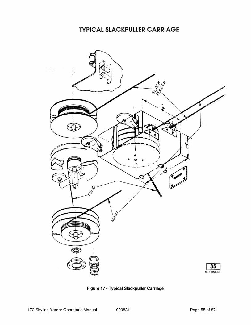
172 Skyline Yarder Operator's Manual 099831- Page 55 of 87
Figure 17 - Typical Slackpuller Carriage
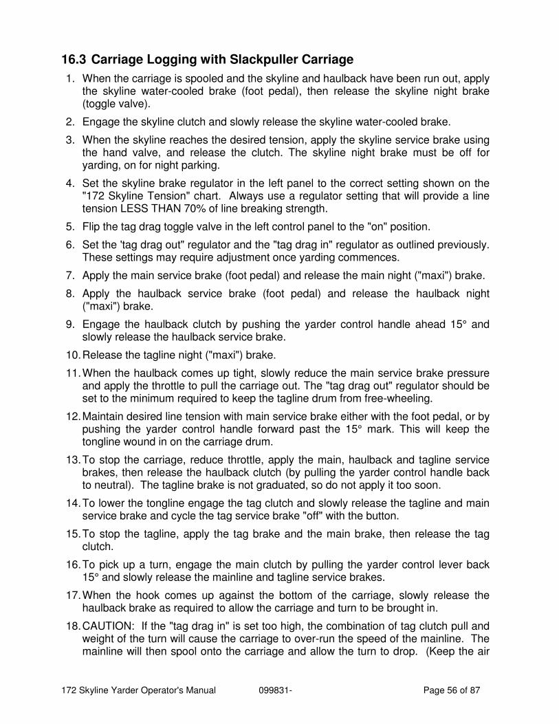
172 Skyline Yarder Operator's Manual 099831- Page 56 of 87
16.3 Carriage Logging with Slackpuller Carriage
1. When the carriage is spooled and the skyline and haulback have been run out, apply the skyline water-cooled brake (foot pedal), then release the skyline night brake (toggle valve).
2. Engage the skyline clutch and slowly release the skyline water-cooled brake.
3. When the skyline reaches the desired tension, apply the skyline service brake using the hand valve, and release the clutch. The skyline night brake must be off for yarding, on for night parking.
4. Set the skyline brake regulator in the left panel to the correct setting shown on the "172 Skyline Tension" chart. Always use a regulator setting that will provide a line tension LESS THAN 70% of line breaking strength.
5. Flip the tag drag toggle valve in the left control panel to the "on" position.
6. Set the 'tag drag out" regulator and the "tag drag in" regulator as outlined previously. These settings may require adjustment once yarding commences.
7. Apply the main service brake (foot pedal) and release the main night ("maxi") brake.
8. Apply the haulback service brake (foot pedal) and release the haulback night ("maxi") brake.
9. Engage the haulback clutch by pushing the yarder control handle ahead 15° and slowly release the haulback service brake.
10. Release the tagline night ("maxi") brake.
11. When the haulback comes up tight, slowly reduce the main service brake pressure and apply the throttle to pull the carriage out. The "tag drag out" regulator should be set to the minimum required to keep the tagline drum from free-wheeling.
12. Maintain desired line tension with main service brake either with the foot pedal, or by pushing the yarder control handle forward past the 15° mark. This will keep the tongline wound in on the carriage drum.
13. To stop the carriage, reduce throttle, apply the main, haulback and tagline service brakes, then release the haulback clutch (by pulling the yarder control handle back to neutral). The tagline brake is not graduated, so do not apply it too soon.
14. To lower the tongline engage the tag clutch and slowly release the tagline and main service brake and cycle the tag service brake "off" with the button.
15. To stop the tagline, apply the tag brake and the main brake, then release the tag clutch.
16. To pick up a turn, engage the main clutch by pulling the yarder control lever back 15° and slowly release the mainline and tagline service brakes.
17. When the hook comes up against the bottom of the carriage, slowly release the haulback brake as required to allow the carriage and turn to be brought in.
18. CAUTION: If the "tag drag in" is set too high, the combination of tag clutch pull and weight of the turn will cause the carriage to over-run the speed of the mainline. The mainline will then spool onto the carriage and allow the turn to drop. (Keep the air
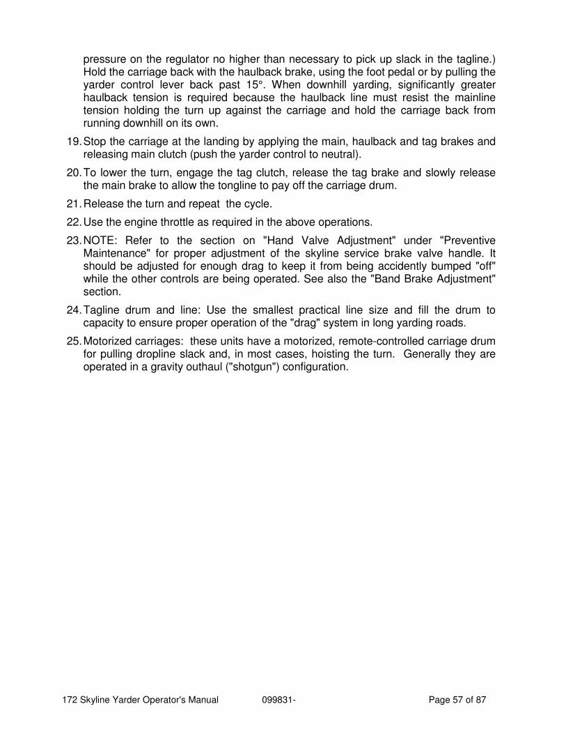
172 Skyline Yarder Operator's Manual 099831- Page 57 of 87
pressure on the regulator no higher than necessary to pick up slack in the tagline.) Hold the carriage back with the haulback brake, using the foot pedal or by pulling the yarder control lever back past 15°. When downhill yarding, significantly greater haulback tension is required because the haulback line must resist the mainline tension holding the turn up against the carriage and hold the carriage back from running downhill on its own.
19. Stop the carriage at the landing by applying the main, haulback and tag brakes and releasing main clutch (push the yarder control to neutral).
20. To lower the turn, engage the tag clutch, release the tag brake and slowly release the main brake to allow the tongline to pay off the carriage drum.
21. Release the turn and repeat the cycle.
22. Use the engine throttle as required in the above operations.
23. NOTE: Refer to the section on "Hand Valve Adjustment" under "Preventive Maintenance" for proper adjustment of the skyline service brake valve handle. It should be adjusted for enough drag to keep it from being accidently bumped "off" while the other controls are being operated. See also the "Band Brake Adjustment" section.
24. Tagline drum and line: Use the smallest practical line size and fill the drum to capacity to ensure proper operation of the "drag" system in long yarding roads.
25. Motorized carriages: these units have a motorized, remote-controlled carriage drum for pulling dropline slack and, in most cases, hoisting the turn. Generally they are operated in a gravity outhaul ("shotgun") configuration.
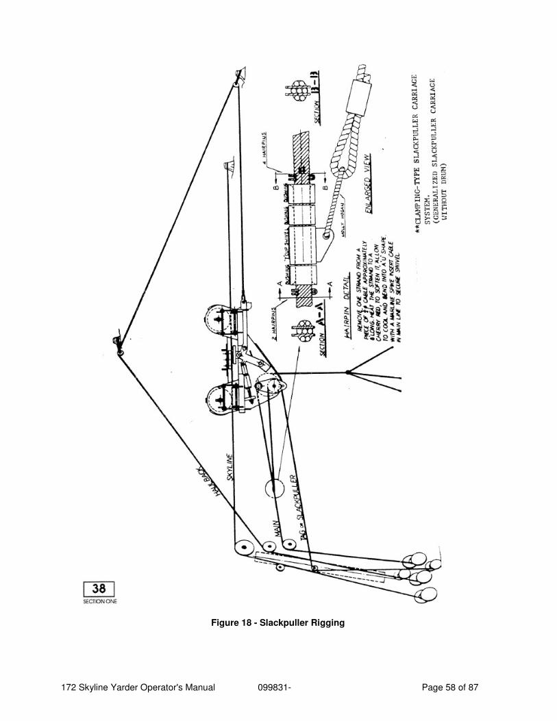
172 Skyline Yarder Operator's Manual 099831- Page 58 of 87
Figure 18 - Slackpuller Rigging
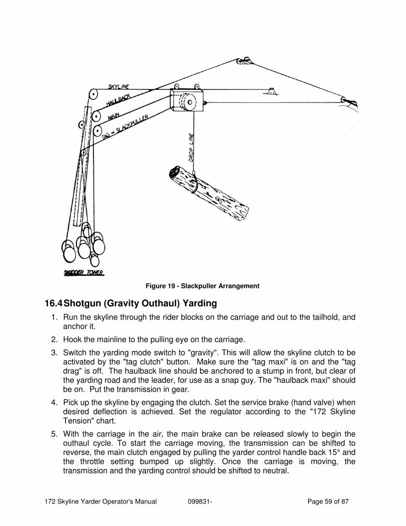
172 Skyline Yarder Operator's Manual 099831- Page 59 of 87
Figure 19 - Slackpuller Arrangement
16.4 Shotgun (Gravity Outhaul) Yarding
1. Run the skyline through the rider blocks on the carriage and out to the tailhold, and anchor it.
2. Hook the mainline to the pulling eye on the carriage.
3. Switch the yarding mode switch to "gravity". This will allow the skyline clutch to be activated by the "tag clutch" button. Make sure the "tag maxi" is on and the "tag drag" is off. The haulback line should be anchored to a stump in front, but clear of the yarding road and the leader, for use as a snap guy. The "haulback maxi" should be on. Put the transmission in gear.
4. Pick up the skyline by engaging the clutch. Set the service brake (hand valve) when desired deflection is achieved. Set the regulator according to the "172 Skyline Tension" chart.
5. With the carriage in the air, the main brake can be released slowly to begin the outhaul cycle. To start the carriage moving, the transmission can be shifted to reverse, the main clutch engaged by pulling the yarder control handle back 15° and the throttle setting bumped up slightly. Once the carriage is moving, the transmission and the yarding control should be shifted to neutral.
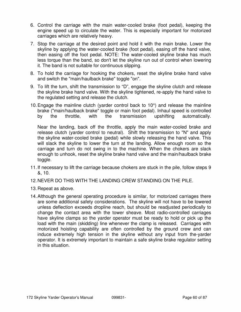
172 Skyline Yarder Operator's Manual 099831- Page 60 of 87
6. Control the carriage with the main water-cooled brake (foot pedal), keeping the engine speed up to circulate the water. This is especially important for motorized carriages which are relatively heavy.
7. Stop the carriage at the desired point and hold it with the main brake. Lower the skyline by applying the water-cooled brake (foot pedal), easing off the hand valve, then easing off the foot pedal. NOTE: The water-cooled skyline brake has much less torque than the band, so don't let the skyline run out of control when lowering it. The band is not suitable for continuous slipping.
8. To hold the carriage for hooking the chokers, reset the skyline brake hand valve and switch the "main/haulback brake" toggle "on".
9. To lift the turn, shift the transmission to “D”, engage the skyline clutch and release the skyline brake hand valve. With the skyline tightened, re-apply the hand valve to the regulated setting and release the clutch.
10. Engage the mainline clutch (yarder control back to 10°) and release the mainline brake ("main/haulback brake" toggle or main foot pedal). Inhaul speed is controlled by the throttle, with the transmission upshifting automatically. Near the landing, back off the throttle, apply the main water-cooled brake and release clutch (yarder control to neutral). Shift the transmission to "N" and apply the skyline water-cooled brake (pedal) while slowly releasing the hand valve. This will slack the skyline to lower the turn at the landing. Allow enough room so the carriage and turn do not swing in to the machine. When the chokers are slack enough to unhook, reset the skyline brake hand valve and the main/haulback brake toggle.
11. If necessary to lift the carriage because chokers are stuck in the pile, follow steps 9 &, 10.
12. NEVER DO THIS WITH THE LANDING CREW STANDING ON THE PILE.
13. Repeat as above.
14. Although the general operating procedure is similar, for motorized carriages there are some additional safety considerations. The skyline will not have to be lowered unless deflection exceeds dropline reach, but should be readjusted periodically to change the contact area with the tower sheave. Most radio-controlled carriages have skyline clamps so the yarder operator must be ready to hold or pick up the load with the main (skidding) line whenever the clamp is released. Carriages with motorized hoisting capability are often controlled by the ground crew and can induce extremely high tension in the skyline without any input from the-yarder operator. It is extremely important to maintain a safe skyline brake regulator setting in this situation.
172 Skyline Yarder Operator's Manual 099831- Page 61 of 87
Figure 20 - Shotgun Arrangement
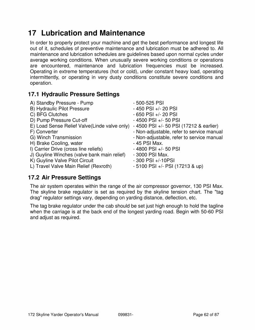
172 Skyline Yarder Operator's Manual 099831- Page 62 of 87
17 Lubrication and Maintenance In order to properly protect your machine and get the best performance and longest life out of it, schedules of preventive maintenance and lubrication must be adhered to. All maintenance and lubrication schedules are guidelines based upon normal cycles under average working conditions. When unusually severe working conditions or operations are encountered, maintenance and lubrication frequencies must be increased. Operating in extreme temperatures (hot or cold), under constant heavy load, operating intermittently, or operating in very dusty conditions constitute severe conditions and operation.
17.1 Hydraulic Pressure Settings
A) Standby Pressure - Pump - 500-525 PSI B) Hydraulic Pilot Pressure - 450 PSI +/- 20 PSI C) BFG Clutches - 650 PSI +/- 20 PSI D) Pump Pressure Cut-off - 4500 PSI +/- 50 PSI E) Load Sense Relief Valve(Linde valve only) - 4500 PSI +/- 50 PSI (17212 & earlier) F) Converter - Non-adjustable, refer to service manual G) Winch Transmission - Non-adjustable, refer to service manual H) Brake Cooling, water - 45 PSI Max. I) Carrier Drive (cross line reliefs) - 4800 PSI +/- 50 PSI J) Guyline Winches (valve bank main relief) - 3000 PSI Max. K) Guyline Valve Pilot Circuit - 300 PSI +/-10PSI L) Travel Valve Main Relief (Rexroth) - 5100 PSI +/- PSI (17213 & up)
17.2 Air Pressure Settings
The air system operates within the range of the air compressor governor, 130 PSI Max. The skyline brake regulator is set as required by the skyline tension chart. The "tag drag" regulator settings vary, depending on yarding distance, deflection, etc.
The tag brake regulator under the cab should be set just high enough to hold the tagline when the carriage is at the back end of the longest yarding road. Begin with 50-60 PSI and adjust as required.
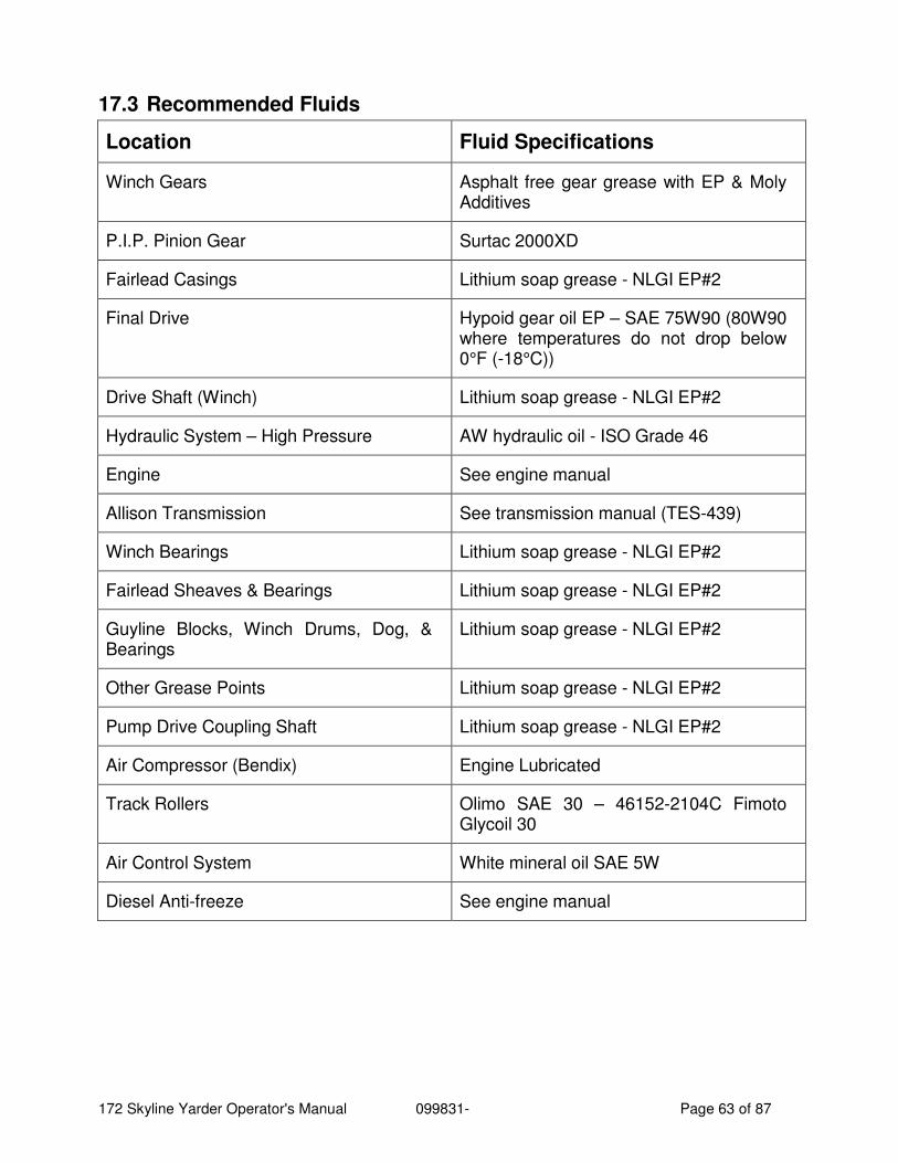
172 Skyline Yarder Operator's Manual 099831- Page 63 of 87
17.3 Recommended Fluids
Location Fluid Specifications
Winch Gears Asphalt free gear grease with EP & Moly Additives
P.I.P. Pinion Gear Surtac 2000XD
Fairlead Casings Lithium soap grease - NLGI EP#2
Final Drive Hypoid gear oil EP – SAE 75W90 (80W90 where temperatures do not drop below 0°F (-18°C))
Drive Shaft (Winch) Lithium soap grease - NLGI EP#2
Hydraulic System – High Pressure AW hydraulic oil - ISO Grade 46
Engine See engine manual
Allison Transmission See transmission manual (TES-439)
Winch Bearings Lithium soap grease - NLGI EP#2
Fairlead Sheaves & Bearings Lithium soap grease - NLGI EP#2
Guyline Blocks, Winch Drums, Dog, & Bearings
Lithium soap grease - NLGI EP#2
Other Grease Points Lithium soap grease - NLGI EP#2
Pump Drive Coupling Shaft Lithium soap grease - NLGI EP#2
Air Compressor (Bendix) Engine Lubricated
Track Rollers Olimo SAE 30 – 46152-2104C Fimoto Glycoil 30
Air Control System White mineral oil SAE 5W
Diesel Anti-freeze See engine manual
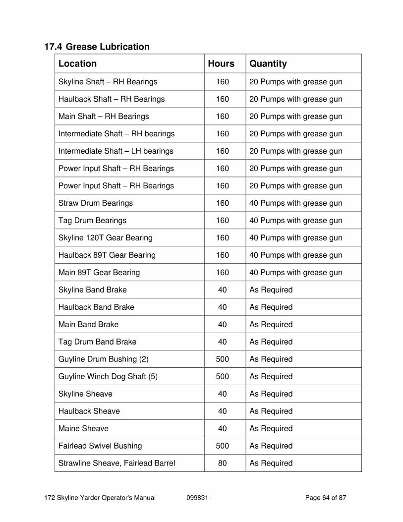
172 Skyline Yarder Operator's Manual 099831- Page 64 of 87
17.4 Grease Lubrication
Location Hours Quantity
Skyline Shaft – RH Bearings 160 20 Pumps with grease gun
Haulback Shaft – RH Bearings 160 20 Pumps with grease gun
Main Shaft – RH Bearings 160 20 Pumps with grease gun
Intermediate Shaft – RH bearings 160 20 Pumps with grease gun
Intermediate Shaft – LH bearings 160 20 Pumps with grease gun
Power Input Shaft – RH Bearings 160 20 Pumps with grease gun
Power Input Shaft – RH Bearings 160 20 Pumps with grease gun
Straw Drum Bearings 160 40 Pumps with grease gun
Tag Drum Bearings 160 40 Pumps with grease gun
Skyline 120T Gear Bearing 160 40 Pumps with grease gun
Haulback 89T Gear Bearing 160 40 Pumps with grease gun
Main 89T Gear Bearing 160 40 Pumps with grease gun
Skyline Band Brake 40 As Required
Haulback Band Brake 40 As Required
Main Band Brake 40 As Required
Tag Drum Band Brake 40 As Required
Guyline Drum Bushing (2) 500 As Required
Guyline Winch Dog Shaft (5) 500 As Required
Skyline Sheave 40 As Required
Haulback Sheave 40 As Required
Maine Sheave 40 As Required
Fairlead Swivel Bushing 500 As Required
Strawline Sheave, Fairlead Barrel 80 As Required
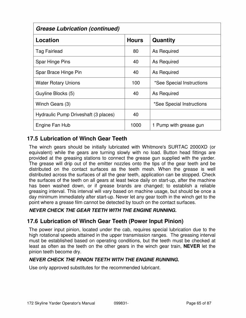
172 Skyline Yarder Operator's Manual 099831- Page 65 of 87
Grease Lubrication (continued)
Location Hours Quantity
Tag Fairlead 80 As Required
Spar Hinge Pins 40 As Required
Spar Brace Hinge Pin 40 As Required
Water Rotary Unions 100 *See Special Instructions
Guyline Blocks (5) 40 As Required
Winch Gears (3) *See Special Instructions
Hydraulic Pump Driveshaft (3 places) 40
Engine Fan Hub 1000 1 Pump with grease gun
17.5 Lubrication of Winch Gear Teeth
The winch gears should be initially lubricated with Whitmore's SURTAC 2000XD (or equivalent) while the gears are turning slowly with no load. Button head fittings are provided at the greasing stations to connect the grease gun supplied with the yarder. The grease will drip out of the emitter nozzles onto the tips of the gear teeth and be distributed on the contact surfaces as the teeth mesh. When the grease is well distributed across the surfaces of all the gear teeth, application can be stopped. Check the surfaces of the teeth on all gears at least twice daily on start-up, after the machine has been washed down, or if grease brands are changed; to establish a reliable greasing interval. This interval will vary based on machine usage, but should be once a day minimum immediately after start-up. Never let any gear tooth in the winch get to the point where a grease film cannot be detected by touch on the contact surfaces.
NEVER CHECK THE GEAR TEETH WITH THE ENGINE RUNNING.
17.6 Lubrication of Winch Gear Teeth (Power Input Pinion)
The power input pinion, located under the cab, requires special lubrication due to the high rotational speeds attained in the upper transmission ranges. The greasing interval must be established based on operating conditions, but the teeth must be checked at least as often as the teeth on the other gears in the winch gear train, NEVER let the pinion teeth become dry.
NEVER CHECK THE PINION TEETH WITH THE ENGINE RUNNING.
Use only approved substitutes for the recommended lubricant.
172 Skyline Yarder Operator's Manual 099831- Page 66 of 87
17.7 Greasing Instructions for Water Rotary Union
Water rotary unions are normally equipped with lubricated and sealed bearings. These units are equipped with plugs that have been drilled to provide drainage. NO GREASING IS REQUIRED on these units. On some repaired roto unions where the seat in the bearing has failed and has been removed, the grease nipple was installed and greasing procedure as outlined should be followed.
The water rotary unions should be greased with three (3) shots of grease every day per fitting. Have the engine running fast enough to develop a minimum of 10 PSI brake water pressure, while the rotary unions are being greased. It is best to grease while the machine is warm. Should you notice an excessive amount of grease being forced out of the union, this is a clear indication you are over-greasing.
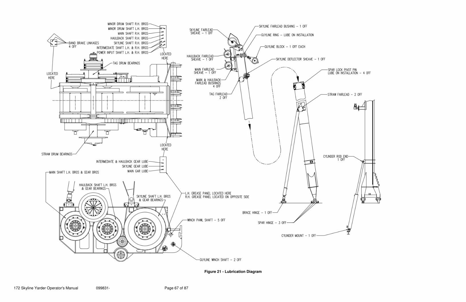
172 Skyline Yarder Operator's Manual 099831- Page 67 of 87
Figure 21 - Lubrication Diagram
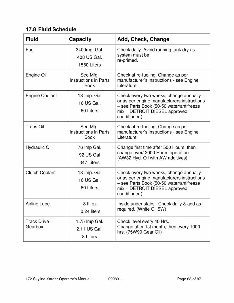
172 Skyline Yarder Operator's Manual 099831- Page 68 of 87
17.8 Fluid Schedule
Fluid Capacity Add, Check, Change
Fuel 340 Imp. Gal.
408 US Gal.
1550 Liters
Check daily. Avoid running tank dry as system must be re-primed.
Engine Oil See Mfg. Instructions in Parts
Book
Check at re-fueling. Change as per manufacturer’s instructions - see Engine Literature
Engine Coolant 13 Imp. Gal
16 US Gal.
60 Liters
Check every two weeks, change annually or as per engine manufacturers instructions – see Parts Book (50-50 water/antifreeze mix + DETROIT DIESEL approved conditioner.)
Trans Oil See Mfg. Instructions in Parts
Book
Check at re-fueling. Change as per manufacturer’s instructions - see Engine Literature
Hydraulic Oil 76 Imp Gal.
92 US Gal
347 Liters
Change first time after 500 Hours, then change ever/ 2000 Hours operation. (AW32 Hyd. Oil with AW additives)
Clutch Coolant 13 Imp. Gal
16 US Gal.
60 Liters
Check every two weeks, change annually or as per engine manufacturers instructions – see Parts Book (50-50 water/antifreeze mix + DETROIT DIESEL approved conditioner.)
Airline Lube 8 fl. oz.
0.24 liters
Inside under stairs. Check daily & add as required. (White Oil 5W)
Track Drive Gearbox
1.75 Imp Gal.
2.11 US Gal.
8 Liters
Check level every 40 Hrs. Change after 1st month, then every 1000 hrs. (75W90 Gear Oil)
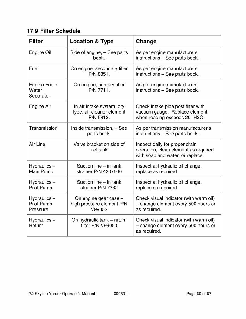
172 Skyline Yarder Operator's Manual 099831- Page 69 of 87
17.9 Filter Schedule
Filter Location & Type Change
Engine Oil Side of engine, – See parts book.
As per engine manufacturers instructions – See parts book.
Fuel On engine, secondary filter P/N 8851.
As per engine manufacturers instructions – See parts book.
Engine Fuel / Water Separator
On engine, primary filter P/N 7711.
As per engine manufacturers instructions – See parts book.
Engine Air In air intake system, dry type, air cleaner element
P/N 5813.
Check intake pipe post filter with vacuum gauge. Replace element when reading exceeds 20” H2O.
Transmission Inside transmission, – See parts book.
As per transmission manufacturer’s instructions – See parts book.
Air Line Valve bracket on side of fuel tank.
Inspect daily for proper drain operation, clean element as required with soap and water, or replace.
Hydraulics – Main Pump
Suction line – in tank strainer P/N 4237660
Inspect at hydraulic oil change, replace as required
Hydraulics – Pilot Pump
Suction line – in tank strainer P/N 7332
Inspect at hydraulic oil change, replace as required
Hydraulics – Pilot Pump Pressure
On engine gear case – high pressure element P/N
V99052
Check visual indicator (with warm oil) – change element every 500 hours or as required.
Hydraulics – Return
On hydraulic tank – return filter P/N V99053
Check visual indicator (with warm oil) – change element every 500 hours or as required.
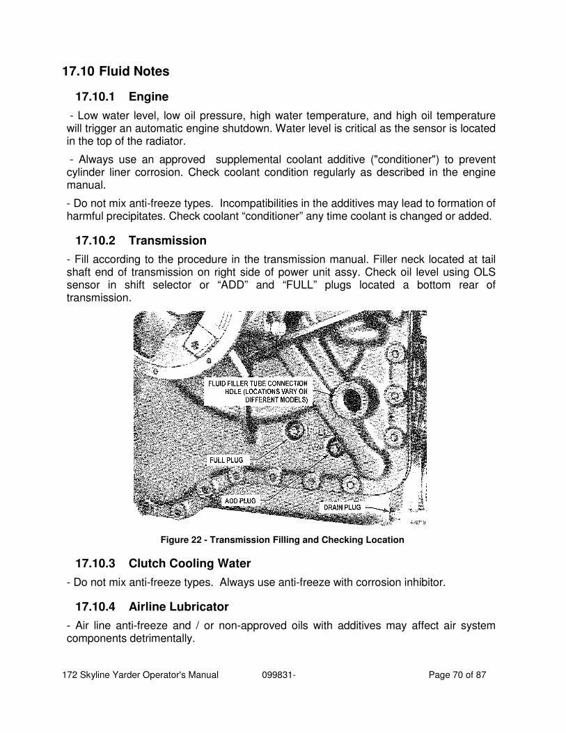
172 Skyline Yarder Operator's Manual 099831- Page 70 of 87
17.10 Fluid Notes
17.10.1 Engine
- Low water level, low oil pressure, high water temperature, and high oil temperature will trigger an automatic engine shutdown. Water level is critical as the sensor is located in the top of the radiator.
- Always use an approved supplemental coolant additive ("conditioner") to prevent cylinder liner corrosion. Check coolant condition regularly as described in the engine manual.
- Do not mix anti-freeze types. Incompatibilities in the additives may lead to formation of harmful precipitates. Check coolant “conditioner” any time coolant is changed or added.
17.10.2 Transmission
- Fill according to the procedure in the transmission manual. Filler neck located at tail shaft end of transmission on right side of power unit assy. Check oil level using OLS sensor in shift selector or “ADD” and “FULL” plugs located a bottom rear of transmission.
Figure 22 - Transmission Filling and Checking Location
17.10.3 Clutch Cooling Water
- Do not mix anti-freeze types. Always use anti-freeze with corrosion inhibitor.
17.10.4 Airline Lubricator
- Air line anti-freeze and / or non-approved oils with additives may affect air system components detrimentally.
172 Skyline Yarder Operator's Manual 099831- Page 71 of 87
17.10.5 Track Drive
- 80W90 grade oils may be used if a complete draw and refill is made. This grade is most suitable for above freezing operation.
17.11 High Torque Clutch Burnishing Procedure
Adjust the clutch valve manifold pressure down to 130-135 PSI (from the normal 650 PSI) for burnishing. Run the winch in first gear with engine speed between 1200 and 1500 RPM while monitoring the clutch drum temperature. When the drum reaches 400-425°F adjust the engine speed to maintain the drum temperature for 3 minutes. Let the clutch drum cool to a maximum of 100°F before repeating the process again in order to ensure that the linings are properly work cured.
It is normal for the clutch lining to smoke during the burnishing procedure. If 400°F has not been reached within 5 minutes stop the burnishing procedure and let the clutch cool for 3-4 hours. Repeat the process with a slightly higher clutch manifold pressure.
The reason it is important to have the linings reach burnishing temperature within five minutes is due to the fact that dragging the clutch beyond this time limit will cause excessive heat to soak through the brake to the expander tube. This heat will shorten the service life of the tube.
17.12 Skyline Band Brake – Care and Burnishing Procedure
Due to the nature of some skyline yarding methods, the skyline band brake may be infrequently released and applied. This can lead to unpredictable brake slipping when the brake is overloaded. In order to increase the predictability and ensure proper operation, the following suggestions are made:
1) Use a warm-up procedure
To clear the skyline brake of moisture, condensation and oxidation a warm-up procedure should be used prior to each shift. During this warm-up procedure, the drum should be powered in and out two or three times against a lightly applied band brake for approximately 20 seconds each.
2) Check the mechanism for proper adjustment
Frequently check the adjustment of the skyline brake actuator mechanism. The large nuts at the top of the band should be adjusted so that the rod in the brake pot travels 1" to 1-1/4" when the maxi brake is applied. (No other brakes applied.)
3) Burnishing new bands. Burnishing this lining wears the lining to produce a better fit. Following is a procedure to "burnish" a new 172 skyline band brake.
1. Ensure the band has 100% contact with the drum.
2. Ensure the band is parallel to the drum and that there are no twists.
3. Apply the brake gently with the transmission in reverse for 1 - 3 minutes. The brake lining should never be subject to temperatures above 450 °F. (230 °C.)
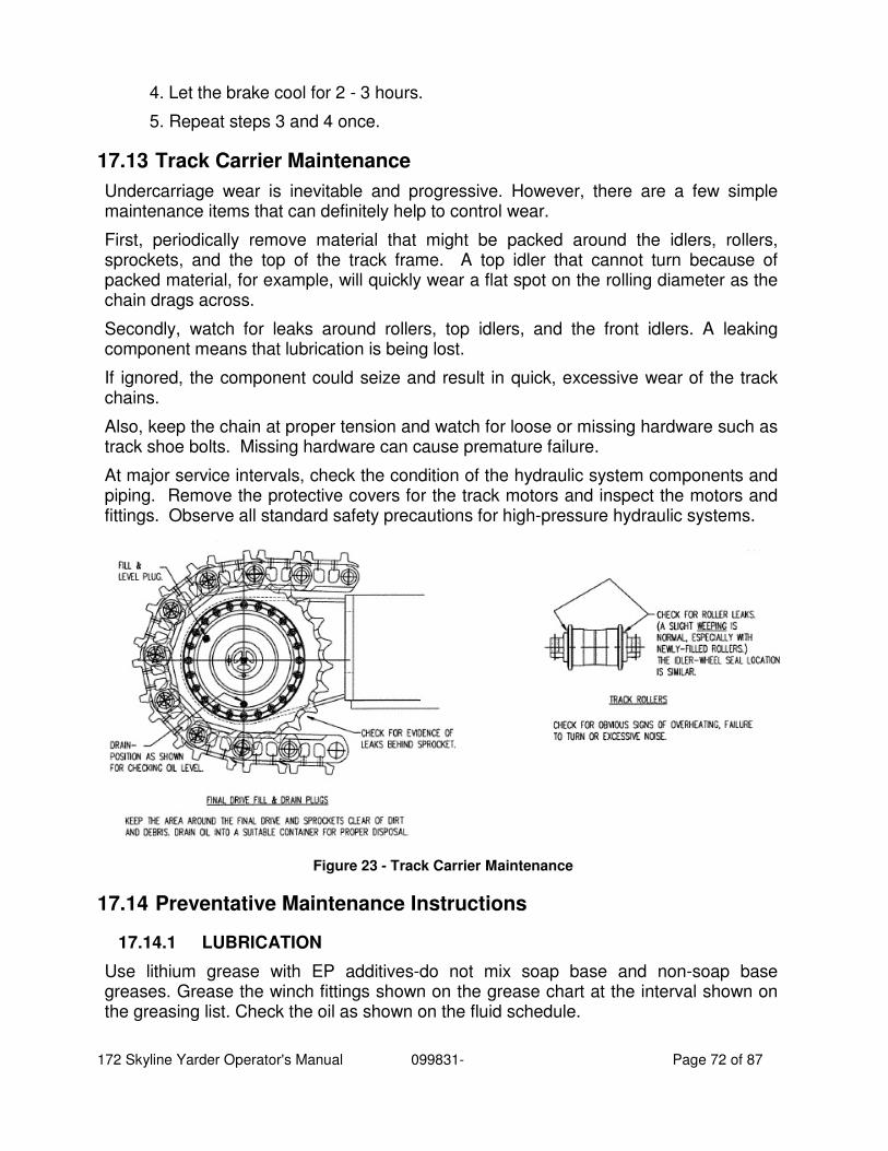
172 Skyline Yarder Operator's Manual 099831- Page 72 of 87
4. Let the brake cool for 2 - 3 hours.
5. Repeat steps 3 and 4 once.
17.13 Track Carrier Maintenance
Undercarriage wear is inevitable and progressive. However, there are a few simple maintenance items that can definitely help to control wear.
First, periodically remove material that might be packed around the idlers, rollers, sprockets, and the top of the track frame. A top idler that cannot turn because of packed material, for example, will quickly wear a flat spot on the rolling diameter as the chain drags across.
Secondly, watch for leaks around rollers, top idlers, and the front idlers. A leaking component means that lubrication is being lost.
If ignored, the component could seize and result in quick, excessive wear of the track chains.
Also, keep the chain at proper tension and watch for loose or missing hardware such as track shoe bolts. Missing hardware can cause premature failure.
At major service intervals, check the condition of the hydraulic system components and piping. Remove the protective covers for the track motors and inspect the motors and fittings. Observe all standard safety precautions for high-pressure hydraulic systems.
Figure 23 - Track Carrier Maintenance
17.14 Preventative Maintenance Instructions
17.14.1 LUBRICATION
Use lithium grease with EP additives-do not mix soap base and non-soap base greases. Grease the winch fittings shown on the grease chart at the interval shown on the greasing list. Check the oil as shown on the fluid schedule.
172 Skyline Yarder Operator's Manual 099831- Page 73 of 87
IMPORTANT - Gear dope instructions - Whitmore's SURTAC 2000XD or equivalent on winch gears. Apply gear dope to the open gears daily. Check gear train at least twice a day while logging. The power input pinion requires special attention due to the high gear speed. The pinion is located near the haulback water-cooled brake.
17.14.2 DRIVE SHAFTS
Inspect the pump and winch drive shafts weekly. Check the condition of the u-joints and sliders and grease accordingly.
17.14.3 CLUTCHES
The strawline pull clutch on the machine is a disc type air actuated clutch. The haulback, main and slackpuller pull clutches are drum types and hydraulically actuated through an expanding tube. The air cooled clutches are designed to operate in an on-off manner. A slipping clutch will wear more rapidly. If the pneumatically operated disc clutches slip, check for a leaking diaphragm, worn plates or discs, low air pressure, obstructions or leaks in air lines or water in the tanks. In the event of a slipping hydraulically actuated clutch, check for a leaking tube, worn or oily shoes, low hydraulic pressure, obstructions, leaks or air in the lines, glazed or worn drums. Check installation of new plates in the pneumatic clutches to ensure adequate movement, for complete disengagement. Similarly, for the hydraulic clutches, there should be adequate clearance between the linings and the drum. Normal air pressure for pneumatic clutches is 120 - 130 PSI, normal pressure for hydraulic clutches is 575 - 650 PSI.
17.14.4 WATER COOLED BRAKES, TAG CLUTCH
This machine is equipped with water cooled disc brakes. The cooling system which consists of a radiator, pump, and reservoir, is charged with an anti-corrosive, anti-freeze and water solution, and is effective to -40°F to -60°F, which should be maintained upon recharging. The system must ALWAYS contain a rust inhibiting ingredient. Overheating: Temperature gauges give warning of coolant temperatures exceeding 180°F in the brake circuit. This is an indication of: a defective pump; loose belt; obstructed coolant passage; damaged radiator fins; low supply of coolant; excessive use of clutch; or faulty instruments. A flow obstruction may be diagnosed by abnormally high pump output pressure or a lack of turbulence in the radiator while the motor is run at high idle. Each of the coolant passages may be tested separately for obstructions by blocking the remaining passages and observing pump output pressure and tank turbulence at high idle conditions. Coolant pressure should be 30 - 40 PSI. Read the manufacturers manual in the parts book for correct method of checking and adjusting for clutch wear.
17.14.5 CARRIER
A) Change oil in planetary (final drive) according to the lube chart. B) On track carriers, check track tension before each move. Check for evidence of oil leaks in final drives and rollers. See also "Track Carrier Maintenance".
17.14.6 ENGINE
See manufacturers maintenance manual
172 Skyline Yarder Operator's Manual 099831- Page 74 of 87
17.14.7 FILTERS
One of the most common problems on a yarder is the contamination of the oil water and fuel systems. Therefore, whenever you experience heating problems or insufficient flow in any of the above mentioned systems, please check your filter and strainer first.
17.14.8 BAND BRAKES, STRAWLINE DISC BRAKE
Check band brakes weekly for foreign material in the linings and proper adjustment of the linkage to keep the actuator stroke in the 1-1/2" to 2-1/4" range. Pay special attention to the condition of the skyline band.
17.14.9 AIR CONDITIONING UNIT
The air conditioning unit in your Madill equipment must be cycled on a bi-weekly basis to ensure that the compressor seals remain lubricated. Refrigerant may leak from the compressor if the unit is not run regularly, particularly over the fall and winter months. The air conditioner warranty does not cover claims for refrigerant loss that are compressor seal related if the unit has not been run on a regular basis.
18 Troubleshooting The electronic control systems will display diagnostic codes for trouble shooting. The engine is programmed to shut down on detection of low oil pressure or coolant level. Some diagnostic codes indicate circuit faults, which can be caused by loose, broken or shorted wires and bent or wet connector pins. Always exercise caution when checking the wiring for faults. If the “STOP ENGINE” or “DO NOT SHIFT” light come on, shut the engine off immediately.
NOTE: Due to the location of the coolant level probe in the radiator top tank a low coolant shutdown can occur when operating the machine on any steep angle, unless the radiator is completely filled.
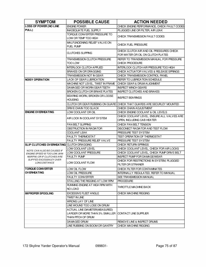
172 Skyline Yarder Operator's Manual 099831- Page 75 of 87
SYMPTOM POSSIBLE CAUSE ACTION NEEDEDENGINE POWER CHECK ENGINE PERFORMANCE, CHECK FAULT CODES
INADEQUATE FUEL SUPPLY PLUGGED LINE OR FILTER, AIR LEAK
TORQUE CONVERTER PRESSURE TO
LOW OR TEMP TOO HIGHCHECK TRANSMISSION FAULT CODES
MALFUNCIONING RELIEF VALVE ON
FUEL PUMPCHECK FUEL PRESSURE
CLUTCHES SLIPPINGCHECK CLUTCH AIR AND OIL PRESSURES CHECK
FOR WATER OR OIL ON CLUTCH PLATES
TRANSMISSION CLUTCH PRESSURE
TOO LOW
REFER TO TRANSMISSION MANUAL FOR PRESSURE
CHECK PROCEDURE
INTERLOCK CLUTCH APPLIED INTERLOCK CLUTCH AIR PRESSURE TOO HIGH
BRAKES ON OR DRAGGING CHECK ACTUATOR VALVES & RELEASE SPRINGS
TRANSMISSION NOT IN GEAR CHECK TRANSMISSION CONTROL PANEL
NOISY OPERATION LACK OF GEAR LUBRICATION REFER TO LUBRICATION SCHEDULE
MACHINE NOT LEVEL, TWIST IN FRAME CHECK GEAR & DRUM ALIGNMENT
DAMAGED OR WORN GEAR TEETH INSPECT WINCH GEARS
BROKEN CLUTCH OR BRAKE PLATES INSPECT CLUTCHES AND BRAKES
BEARING WORN, BROKEN OR LOOSE
HOUSINGINSPECT BEARINGS
CLUTCH OR GEAR RUBBING ON GUARD CHECK THAT GUARDS ARE SECURLEY MOUNTED
DRIVE CHAIN TOO SLACK CHECK CHAIN ADJUSTMENT
ENGINE OVERHEATING LOW COOLANT OR OIL CHECK ENGINE COOLANT & OIL LEVELS
AIR LOCK IN COOLANT SYSTEMCHECK COOLANT LEVEL, ENSURE ALL VALVES ARE
OPEN, INCLUDING CAB HEATER
FAN BELT SLIPPING CHECK FAN BELT TENSION
OBSTRUCTION IN RADIATOR DISCONECT RADIATOR AND TEST FLOW
COOLANT LEAK PRESSURE TEST SYSTEM
FAULTY THERMOSTAT TEST OPERATION OF THERMOSTAT
FAULTY PRESSURE RELIEF VALVE PRESSURE TEST SYSTEM
SLIP CLUTCHES OVERHEATING CLUTCH DRAGGING CHECK RETURN SPRINGS
LOW COOLANT LEVEL CHECK COOLANT LEVEL, CHECK FOR AIR LOCKS
LOW COOLANT PRESSURE CHECK COOLANT LEVEL, CHECK PUMP DRIVE BELT
FAULTY PUMP INSPECT PUMP FOR DAMAGE/WEAR
LOW COOLANT FLOWCHECK FOR RESTRICTIONS IN SYSTEM, PLUGGED
FILTER OR STRAINER
LOW OIL FLOW CHECK FILTER FOR CONTAMINATES
LOW OIL PRESSURE INTERNALLY REGULATED, REFER TO MANUAL
FAULTY CONVERTER SEE TRANSMISSION MANUAL
STALLING THE RIGGING AT LOW RPM PROCEDURE
RUNNING ENGINE AT HIGH RPM WITH
NO LOADTHROTTLE MACHINE BACK
IMPROPER SPOOLING EXCESSIVE FLEET ANGLE CHECK MACHINE RIGGING
TWIST IN LINE
WRONG LAY OF LINE
LINE WOUND TOO LOSE ON DRUM
ACTUAL LINE DIAMETER(MEASURED)
LARGER OR MORE THAN 3% SMALLER
THAN PITCH OF DRUM
CONTACT LINE SUPPLIER
DAMAGED DRUM REMOVE LINE & INSPECT DRUMS
LINE RUBBING ON BOOM OR GANTRY CHECK MACHINE RIGGING
LOSS OF POWER (NO LINE
PULL)
NOTE: CAN ALSO BE CAUSED IF
ENGINE SPEED IS TOO LOW, (M IN
1100RPM ) OR IF CLUTCHES ARE
SLIPPED EXCESSIVLEY OVER
LONG DISTANCE
TORQUE CONVERTER
OVERHEATING
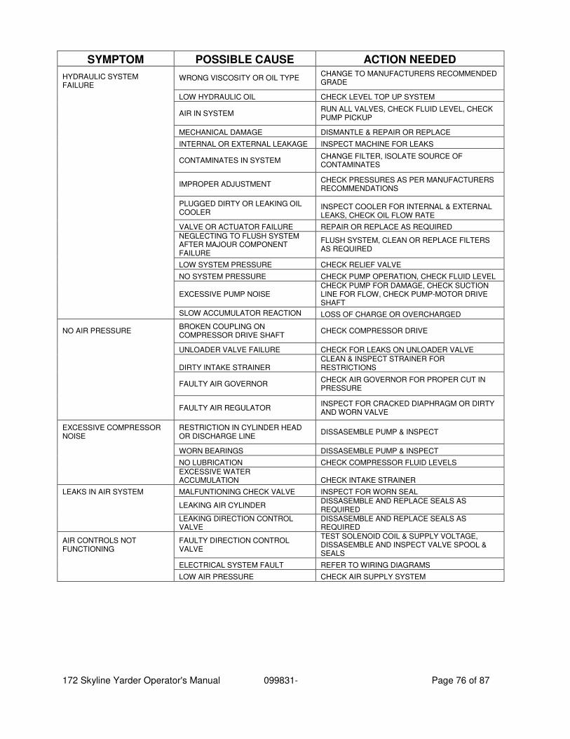
172 Skyline Yarder Operator's Manual 099831- Page 76 of 87
SYMPTOM POSSIBLE CAUSE ACTION NEEDED
HYDRAULIC SYSTEM FAILURE
WRONG VISCOSITY OR OIL TYPE CHANGE TO MANUFACTURERS RECOMMENDED GRADE
LOW HYDRAULIC OIL CHECK LEVEL TOP UP SYSTEM
AIR IN SYSTEM
RUN ALL VALVES, CHECK FLUID LEVEL, CHECK PUMP PICKUP
MECHANICAL DAMAGE DISMANTLE & REPAIR OR REPLACE
INTERNAL OR EXTERNAL LEAKAGE INSPECT MACHINE FOR LEAKS
CONTAMINATES IN SYSTEM
CHANGE FILTER, ISOLATE SOURCE OF CONTAMINATES
IMPROPER ADJUSTMENT CHECK PRESSURES AS PER MANUFACTURERS RECOMMENDATIONS
PLUGGED DIRTY OR LEAKING OIL COOLER
INSPECT COOLER FOR INTERNAL & EXTERNAL LEAKS, CHECK OIL FLOW RATE
VALVE OR ACTUATOR FAILURE REPAIR OR REPLACE AS REQUIRED
NEGLECTING TO FLUSH SYSTEM AFTER MAJOUR COMPONENT FAILURE
FLUSH SYSTEM, CLEAN OR REPLACE FILTERS AS REQUIRED
LOW SYSTEM PRESSURE CHECK RELIEF VALVE
NO SYSTEM PRESSURE CHECK PUMP OPERATION, CHECK FLUID LEVEL
EXCESSIVE PUMP NOISE
CHECK PUMP FOR DAMAGE, CHECK SUCTION LINE FOR FLOW, CHECK PUMP-MOTOR DRIVE SHAFT
SLOW ACCUMULATOR REACTION LOSS OF CHARGE OR OVERCHARGED
NO AIR PRESSURE BROKEN COUPLING ON COMPRESSOR DRIVE SHAFT
CHECK COMPRESSOR DRIVE
UNLOADER VALVE FAILURE CHECK FOR LEAKS ON UNLOADER VALVE
DIRTY INTAKE STRAINER CLEAN & INSPECT STRAINER FOR RESTRICTIONS
FAULTY AIR GOVERNOR
CHECK AIR GOVERNOR FOR PROPER CUT IN PRESSURE
FAULTY AIR REGULATOR
INSPECT FOR CRACKED DIAPHRAGM OR DIRTY AND WORN VALVE
EXCESSIVE COMPRESSOR NOISE
RESTRICTION IN CYLINDER HEAD OR DISCHARGE LINE
DISSASEMBLE PUMP & INSPECT
WORN BEARINGS DISSASEMBLE PUMP & INSPECT
NO LUBRICATION CHECK COMPRESSOR FLUID LEVELS
EXCESSIVE WATER ACCUMULATION CHECK INTAKE STRAINER
LEAKS IN AIR SYSTEM MALFUNTIONING CHECK VALVE INSPECT FOR WORN SEAL
LEAKING AIR CYLINDER
DISSASEMBLE AND REPLACE SEALS AS REQUIRED
LEAKING DIRECTION CONTROL VALVE
DISSASEMBLE AND REPLACE SEALS AS REQUIRED
AIR CONTROLS NOT FUNCTIONING
FAULTY DIRECTION CONTROL VALVE
TEST SOLENOID COIL & SUPPLY VOLTAGE, DISSASEMBLE AND INSPECT VALVE SPOOL & SEALS
ELECTRICAL SYSTEM FAULT REFER TO WIRING DIAGRAMS
LOW AIR PRESSURE CHECK AIR SUPPLY SYSTEM
172 Skyline Yarder Operator's Manual 099831- Page 77 of 87
19 Onboard Diagnostics - DDEC V Since the DDEC system is electronic, a battery is required to operate the computer. The system operates at 24 volts. However, in the event of a power supply malfunction, the system will continue to operate at reduced voltage. When this occurs the "Check Engine" light will come on. The engine will only operate at reduced rpm until the battery voltage reaches a point where the ECM will no longer function and the engine shuts down.
Should the "Check Engine" light come on for any reason, the vehicle can still be operated and you can proceed to your destination. This condition should be reported to a DDEC technician as soon as possible.
WARNING:
When the "Stop Engine" light comes on, the computer has detected a major malfunction in the engine that requires immediate attention. It is the operator's responsibility to shut down the engine to avoid serious damage.
The engine can be configured to give a warning only, to ramp down (reduce power), or to shut down. Ramp down will reduce engine rpm to a predetermined speed, but will not shut down the engine. With the 30 second shutdown option the engine will begin a 30 second, stepped, power-down sequence until it shuts down completely. A "Stop Engine Override" can be supplied in case the vehicle is to operate in a critical situation.
NOTE:
The "Stop Engine Override" and "Diagnostic Request" switch is the same.
In this situation the operator may elect to "override" the automatic stop engine sequence by pressing the "Stop Engine Override" switch, located on the instrument panel, until a safe stop can be made. The operator only needs to press the override switch every 15 to 20 seconds to prevent engine shutdown from occurring.
The engine should not be restarted after it has been shut down by the engine protection system unless the problem has been located and corrected.
The conditions that will cause the "Stop Engine" light (SEL) to come on are:
■ High coolant temperature ■ Loss of coolant
■ High oil temperature ■ Low oil pressure
■ Auxiliary shutdown
It is important to point out that whenever the "Check Engine" light (CEL) or the "Stop Engine" light (SEL) comes on, the DDEC computer will determine where the problem is, and will then store this information in its memory.
If the malfunction is intermittent, the "Lights" will come on and go off as the computer senses the changing engine condition.
172 Skyline Yarder Operator's Manual 099831- Page 78 of 87
A special diagnostic tool (Diagnostic Data Reader or "DDR") is available that can be plugged into the engine computer memory to extract information related to the cause of the problem.
Once the malfunction has been corrected, the DDEC system will return the engine to normal operation.
The DDR can distinguish between codes now active and those stored in the ECM memory (inactive).
The malfunction code recorded in the computer memory will remain until it is erased by a technician.
The malfunction code can also be obtained by the operator. A "Diagnostic Request" switch is provided which, when pressed, will cause the "Check Engine" light (CEL) to flash a code number. It will, for example, flash twice...pause...flash five times...pause. In other words, a code 25. See Figure 24
Code 25 indicates all systems are working satisfactorily. The active codes will be flashed on the "Stop Engine" light (SEL) in the order of most recent to least recent occurrence based on engine hours. If there are no active codes, a code "25" will be lashed.
The inactive codes will be flashed on the "Check Engine" light (CEL. If there are no inactive codes, a code "25" will be flashed.
Note that only one light will be flashing codes at any time. When code flashing is initiated, the active codes (or code "25") will be flashed on the SEL. Then the inactive codes (or code "25") will be flashed on the CEL. When all the inactive codes (or code "25") have been flashed, the process of flashing all the active codes followed by all the inactive codes will repeat until the conditions for code lashing are no longer satisfied.
The codes will continue to flash and repeat as long as the diagnostic request switch is held in the "On" position with the ignition on. Other diagnostic codes are listed in Table 2.
TO READ CODES: Use the diagnostic data reader or depress and hold the diagnostic request switch with the ignition on, engine at idle or not running. Press and hold the switch. Active codes will be flashed on the "Stop Engine" light (SEL) followed by the inactive codes being flashed on the "Check Engine" light (CEL). The cycle will repeat until the operator releases the diagnostic request switch.
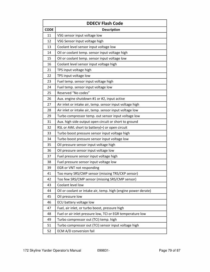
172 Skyline Yarder Operator's Manual 099831- Page 79 of 87
DDECV Flash Code
CODE Description
11 VSG sensor input voltage low
12 VSG Sensor Input voltage high
13 Coolant level sensor input voltage low
14 Oil or coolant temp. sensor input voltage high
15 Oil or coolant temp. sensor input voltage low
16 Coolant level sensor input voltage high
21 TPS input voltage high
22 TPS input voltage low
23 Fuel temp. sensor input voltage high
24 Fuel temp. sensor input voltage low
25 Reserved “No codes”
26 Aux. engine shutdown #1 or #2, input active
27 Air inlet or intake air, temp. sensor input voltage high
28 Air inlet or intake air, temp. sensor input voltage low
29 Turbo compressor temp. out sensor input voltage low
31 Aux. high side output open circuit or short to ground
32 RSL or AWL short to battery(+) or open circuit
33 Turbo boost pressure sensor input voltage high
34 Turbo boost pressure sensor input voltage low
35 Oil pressure sensor input voltage high
36 Oil pressure sensor input voltage low
37 Fuel pressure sensor input voltage high
38 Fuel pressure sensor input voltage low
39 EGR or VNT not responding
41 Too many SRS/CMP sensor (missing TRS/CKP sensor)
42 Too few SRS/CMP sensor (missing SRS/CMP sensor)
43 Coolant level low
44 Oil or coolant or intake air, temp. high (engine power derate)
45 Oil pressure low
46 ECU battery voltage low
47 Fuel, air inlet, or turbo boost, pressure high
48 Fuel or air inlet pressure low, TCI or EGR temperature low
49 Turbo compressor out (TCI) temp. high
51 Turbo compressor out (TCI) sensor input voltage high
52 ECM A/D conversion fail
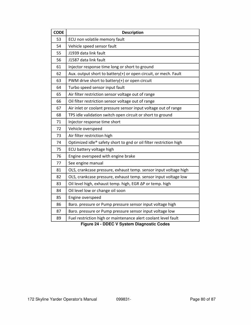
172 Skyline Yarder Operator's Manual 099831- Page 80 of 87
CODE Description
53 ECU non volatile memory fault
54 Vehicle speed sensor fault
55 J1939 data link fault
56 J1587 data link fault
61 Injector response time long or short to ground
62 Aux. output short to battery(+) or open circuit, or mech. Fault
63 PWM drive short to battery(+) or open circuit
64 Turbo speed sensor input fault
65 Air filter restriction sensor voltage out of range
66 Oil filter restriction sensor voltage out of range
67 Air inlet or coolant pressure sensor input voltage out of range
68 TPS idle validation switch open circuit or short to ground
71 Injector response time short
72 Vehicle overspeed
73 Air filter restriction high
74 Optimized idle® safety short to gnd or oil filter restriction high
75 ECU battery voltage high
76 Engine overspeed with engine brake
77 See engine manual
81 OLS, crankcase pressure, exhaust temp. sensor input voltage high
82 OLS, crankcase pressure, exhaust temp. sensor input voltage low
83 Oil level high, exhaust temp. high, EGR ΔP or temp. high
84 Oil level low or change oil soon
85 Engine overspeed
86 Baro. pressure or Pump pressure sensor input voltage high
87 Baro. pressure or Pump pressure sensor input voltage low
89 Fuel restriction high or maintenance alert coolant level fault
Figure 24 - DDEC V System Diagnostic Codes
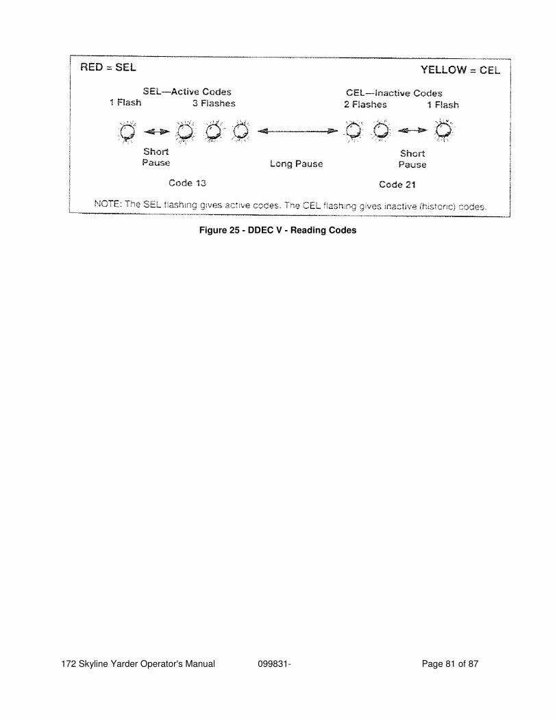
172 Skyline Yarder Operator's Manual 099831- Page 81 of 87
Figure 25 - DDEC V - Reading Codes

172 Skyline Yarder Operator's Manual 099831- Page 82 of 87
20 Transmission Diagnostic Trouble Codes
20.1 Overview
Diagnostic features are provided with the transmission control system to assist in troubleshooting of malfunctions and/or the monitoring of specific operating parameters. When a control system malfunction is detected, a series of Diagnostic Trouble Codes (DTCs) are used to identify and clarify the nature of the malfunction. These DTCs are each named by a 5 character alphanumeric string that refers to a diagnostic algorithm running pass/fail tests to help identify a malfunction in the transmission or vehicle operation. Most DTCs have some kind of diagnostic response that the operator notices, such as an illuminated CHECK TRANS light, selector display change, lock in range, or inhibit shifts condition. DTCs are logged in the Transmission Control Module (TCM) memory by severity and by their active/inactive status with the most severe and active codes listed first. A maximum of five DTCs (numbered d1-d5) from most recent to oldest may be read from the shift selector. As DTCs are added, the oldest inactive DTC (historic) is dropped from the list. If all DTCs are active, the DTC with the lowest priority is dropped from the list. An active code is any code that is current in the TCM decision-making process and has failed the DTC test(s) associated with that specific diagnostic algorithm. Historical codes, which are by definition inactive, are codes that are no longer failing their algorithm but are retained in the TCM in order to help the technician analyze possible causes and provide them direction if the vehicle is brought in before they are cleared from the queue. DTCs can be cleared manually by the operator or they clear automatically from last (d5) to first (d1) in the queue after a number of engine starts, without becoming active again.
20.2 Diagnostic Trouble Code Response
The electronic control system is programmed to inform the operator of a problem with the transmission system via the CHECK TRANS light and shift selector display while it automatically takes action to protect the operator, vehicle, and transmission. When the Transmission Control Module (TCM) flags a Diagnostic Trouble Code (DTC) as active, the TCM may take a combination of diagnostic responses. The TCM separately stores the active and historical (nonactive) codes. An active code is any code that is current in the TCM decision-making process. Historical codes are codes that are retained in the TCM's memory and will not necessarily affect the TCM decision-making process. Historical codes are useful in determining if a problem is: • Isolated • Intermittent
172 Skyline Yarder Operator's Manual 099831- Page 83 of 87
• Results from a previous malfunction When the diagnostic mode is entered, the first code (position d1) is displayed as follows (each display item lasts for about one second): d, 1, main code (two digits displayed one digit at a time), subcode (two digits displayed one digit at a time), sequence repeats. Press the MODE button momentarily to display codes for positions d2-d5 in the same manner. After a fixed number of ignition cycles, a code may be deleted from memory if it has not recurred. The shift selector diagnostic mode will end automatically after two minutes without operator input.
20.2.1 Check Trans Light
Each time the engine is started, the CHECK TRANS light illuminates briefly for a bulb check. After a few seconds it should turn off. If the CHECK TRANS light does not illuminate briefly after the ignition is turned on, or if the CHECK TRANS light remains steadily on after ignition and engine start, have the vehicle and transmission system checked by a qualified Allison Transmission technician. If the CHECK TRANS light is steadily illuminated due to an active OTC, the shift selector blinks the SELECT RANGE and only shows a range the transmission has locked into in the MONITOR window of the selector, seek immediate attention from a qualified Allison Transmission technician. Perform service as soon as possible in order to minimize the potential for damage to the transmission or vehicle. The transmission can be operated for a short time in the current attained range in order to get the vehicle to a safe location for service assistance. If the vehicle engine is turned off, prepare for the possibility that at engine restart the transmission may be locked in N (Neutral) and will not accept operator requests to change range if a OTC that causes a CHECK TRANS light is active at time of engine restart. _______________________________________________________________________ NOTE: Some OTCs may be logged without the TCM activating the CHECK TRANS light. Contact your Allison Transmission authorized service outlet whenever there is a transmission-related concern. They have the equipment to access and troubleshoot OTCs.
20.3 Using Shift Selector for Accessing Diagnostics Information
20.3.1 Interpreting DTC Message Sequence across Selector Displays
Up to five DTCs may be displayed from the selector once the diagnostic display mode has been initiated by the operator (refer to 6.3.4 READ/CLEAR DIAGNOSTIC TROUBLE CODES (DTCs) USING LEVER SHIFT SELECTOR, and 6.3.5 READ/CLEAR DIAGNOSTIC TROUBLE CODES (DTCs) USING KEYPAD PUSHBUTTON SHIFT SELECTOR).
172 Skyline Yarder Operator's Manual 099831- Page 84 of 87
DTCs are seven characters in length and are displayed in four character strings. Three of the four character strings consist of two characters. The first position in the character string is one character in length and it is the code type, designated by a P or U. Each character string displays for 1-2 seconds in a sequential pattern in the selector display until the DTC completes the message cycle. The message continues to repeat itself until the operator presses the MODE button to read the next DTC in the queue (if any) or requests to exit diagnostics mode (refer to 6.3.4.2 EXITING DIAGNOSTIC MODE USING LEVER SHIFT SELECTOR and 6.3.5.2 EXITING DIAGNOSTIC MODE USING KEYPAD PUSHBUTTON SHIFT SELECTOR). The diagnostics mode times out and returns the selector to normal operating mode after approximately 10 minutes of operator inactivity. The first two characters in the first string displays the position of the DTC in the queue, d1 (newest) through d5 (oldest). The next five characters that display in the selector define the DTC. The following example illustrates the method for displaying any DTC stored in the queue. In this example we have the newest code, d1, as it would appear in the selector display for DTC P2637:
Displaying DTC P2637 Stored in the Queue RANGE SELECT WINDOW RANGE MONITOR WINDOW
d* 1* (blank display) P**
2*** 6*** 3**** 7****
* d1 Code list position (Note: d1 = newest code, d5 = oldest code in memory) ** Code Type *** Main Code **** Sub Code
• d1; P; 26; 37 repeats until the next OTC (d2) is accessed by pressing the MODE button or when the operator exits diagnostic display mode. _____________________________________________________________________ NOTE: The MODE indicator on the selector will be illuminated simultaneously with the display of the OTC if the OTC is currently active. If the MODE indicator is not illuminated then the OTC is inactive (historic). Inactive OTCs will not inhibit or limit transmission performance. Only active OTCs limit transmission performance. The inactive codes kept in the queue for reference to assist with troubleshooting an intermittent problem.
20.3.2 Meaning of Mode Indicator in Diagnostic Mode
If the MODE indicator is illuminated, while reading OTCs out of the selector display, the displayed OTC is active. If the MODE indicator is not illuminated, the displayed OTC is inactive (historic).
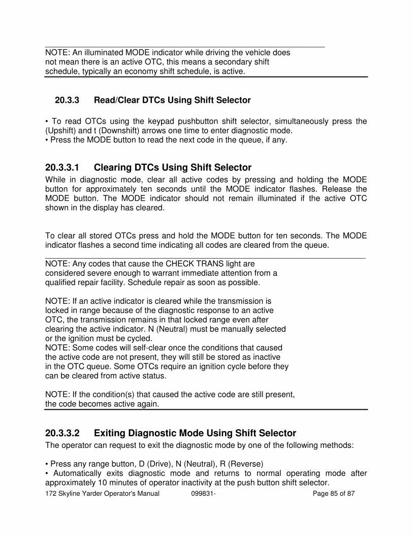
172 Skyline Yarder Operator's Manual 099831- Page 85 of 87
______________________________________________________________ NOTE: An illuminated MODE indicator while driving the vehicle does not mean there is an active OTC, this means a secondary shift schedule, typically an economy shift schedule, is active.
20.3.3 Read/Clear DTCs Using Shift Selector
• To read OTCs using the keypad pushbutton shift selector, simultaneously press the (Upshift) and t (Downshift) arrows one time to enter diagnostic mode. • Press the MODE button to read the next code in the queue, if any.
20.3.3.1 Clearing DTCs Using Shift Selector
While in diagnostic mode, clear all active codes by pressing and holding the MODE button for approximately ten seconds until the MODE indicator flashes. Release the MODE button. The MODE indicator should not remain illuminated if the active OTC shown in the display has cleared. To clear all stored OTCs press and hold the MODE button for ten seconds. The MODE indicator flashes a second time indicating all codes are cleared from the queue. _______________________________________________________________________ NOTE: Any codes that cause the CHECK TRANS light are considered severe enough to warrant immediate attention from a qualified repair facility. Schedule repair as soon as possible. NOTE: If an active indicator is cleared while the transmission is locked in range because of the diagnostic response to an active OTC, the transmission remains in that locked range even after clearing the active indicator. N (Neutral) must be manually selected or the ignition must be cycled. NOTE: Some codes will self-clear once the conditions that caused the active code are not present, they will still be stored as inactive in the OTC queue. Some OTCs require an ignition cycle before they can be cleared from active status. NOTE: If the condition(s) that caused the active code are still present, the code becomes active again.
20.3.3.2 Exiting Diagnostic Mode Using Shift Selector
The operator can request to exit the diagnostic mode by one of the following methods: • Press any range button, D (Drive), N (Neutral), R (Reverse) • Automatically exits diagnostic mode and returns to normal operating mode after approximately 10 minutes of operator inactivity at the push button shift selector.
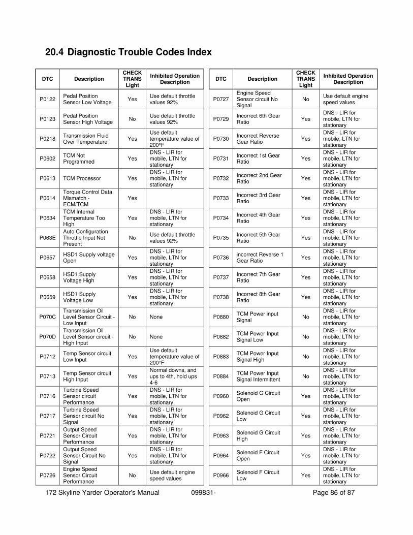
172 Skyline Yarder Operator's Manual 099831- Page 86 of 87
20.4 Diagnostic Trouble Codes Index
DTC Description CHECK TRANS Light
Inhibited Operation Description
P0122 Pedal Position Sensor Low Voltage
Yes Use default throttle values 92%
P0123 Pedal Position Sensor High Voltage
No Use default throttle values 92%
P0218 Transmission Fluid Over Temperature
Yes Use default temperature value of 200°F
P0602 TCM Not Programmed
Yes DNS - LIR for mobile, LTN for stationary
P0613 TCM Processor Yes DNS - LIR for mobile, LTN for stationary
P0614 Torque Control Data Mismatch - ECM/TCM
Yes
P0634 TCM Internal Temperature Too High
Yes DNS - LIR for mobile, LTN for stationary
P063E Auto Configuration Throttle Input Not Present
No Use default throttle values 92%
P0657 HSD1 Supply voltage Open
Yes DNS - LIR for mobile, LTN for stationary
P0658 HSD1 Supply Voltage High
Yes DNS - LIR for mobile, LTN for stationary
P0659 HSD1 Supply Voltage Low
Yes DNS - LIR for mobile, LTN for stationary
P070C Transmission Oil Level Sensor Circuit - Low Input
No None
P070D Transmission Oil Level Sensor circuit - High Input
No None
P0712 Temp Sensor circuit Low Input
Yes Use default temperature value of 200°F
P0713 Temp Sensor circuit High Input
Yes Normal downs, and ups to 4th, hold ups 4-6
P0716 Turbine Speed Sensor circuit Performance
Yes DNS - LIR for mobile, LTN for stationary
P0717 Turbine Speed Sensor circuit No Signal
Yes DNS - LIR for mobile, LTN for stationary
P0721 Output Speed Sensor Circuit Performance
Yes DNS - LIR for mobile, LTN for stationary
P0722 Output Speed Sensor Circuit No Signal
Yes DNS - LIR for mobile, LTN for stationary
P0726 Engine Speed Sensor Circuit Performance
No Use default engine speed values
DTC Description CHECK TRANS Light
Inhibited Operation Description
P0727 Engine Speed Sensor circuit No Signal
No Use default engine speed values
P0729 Incorrect 6th Gear Ratio
Yes DNS - LIR for mobile, LTN for stationary
P0730 Incorrect Reverse Gear Ratio
Yes DNS - LIR for mobile, LTN for stationary
P0731 Incorrect 1st Gear Ratio
Yes DNS - LIR for mobile, LTN for stationary
P0732 Incorrect 2nd Gear Ratio
Yes DNS - LIR for mobile, LTN for stationary
P0733 Incorrect 3rd Gear Ratio
Yes DNS - LIR for mobile, LTN for stationary
P0734 Incorrect 4th Gear Ratio
Yes DNS - LIR for mobile, LTN for stationary
P0735 Incorrect 5th Gear Ratio
Yes DNS - LIR for mobile, LTN for stationary
P0736 incorrect Reverse 1 Gear Ratio
Yes DNS - LIR for mobile, LTN for stationary
P0737 Incorrect 7th Gear Ratio
Yes DNS - LIR for mobile, LTN for stationary
P0738 Incorrect 8th Gear Ratio
Yes DNS - LIR for mobile, LTN for stationary
P0880 TCM Power input Signal
No DNS - LIR for mobile, LTN for stationary
P0882 TCM Power Input Signal Low
No DNS - LIR for mobile, LTN for stationary
P0883 TCM Power Input Signal High
No DNS - LIR for mobile, LTN for stationary
P0884 TCM Power Input Signal Intermittent
No DNS - LIR for mobile, LTN for stationary
P0960 Solenoid G Circuit Open
Yes DNS - LIR for mobile, LTN for stationary
P0962 Solenoid G Circuit Low
Yes DNS - LIR for mobile, LTN for stationary
P0963 Solenoid G Circuit High
Yes DNS - LIR for mobile, LTN for stationary
P0964 Solenoid F Circuit Open
Yes DNS - LIR for mobile, LTN for stationary
P0966 Solenoid F Circuit Low
Yes DNS - LIR for mobile, LTN for stationary

172 Skyline Yarder Operator's Manual 099831- Page 87 of 87
DTC Description CHECK TRANS Light
Inhibited Operation Description
P0967 Solenoid F Circuit High
Yes DNS - LIR for mobile, LTN for stationary
P0968 Solenoid C Circuit Open
Yes DNS - LIR for mobile, LTN for stationary
P0970 Solenoid C Circuit Low
Yes DNS - LIR for mobile, LTN for stationary
P0971 Solenoid C Circuit High
Yes DNS - LIR for mobile, LTN for stationary
P0972 Solenoid H/J Circuit Open
Yes DNS - LIR for mobile, LTN for stationary
P0973 Solenoid H/J Circuit Low
Yes DNS - LIR for mobile, LTN for stationary
P0974 Solenoid H/J Circuit High
Yes DNS - LIR for mobile, LTN for stationary
P0975 Solenoid D Circuit Open
Yes DNS - LIR for mobile, LTN for stationary
P0976 Solenoid D Circuit Low
Yes DNS - LIR for mobile, LTN for stationary
P0977 Solenoid D Circuit High
Yes DNS - LIR for mobile, LTN for stationary
P0978 Solenoid E Circuit Open
Yes DNS - LIR for mobile, LTN for stationary
P0979 Solenoid E Circuit Low
Yes DNS - LIR for mobile, LTN for stationary
P0980 Solenoid E Circuit High
Yes DNS - LIR for mobile, LTN for stationary
P0982 Solenoid K Circuit Open
Yes DNS - LIR for mobile, LTN for stationary
P0983 Solenoid K Circuit Low
Yes DNS - LIR for mobile, LTN for stationary
P0984 Solenoid K Circuit High
Yes DNS - LIR for mobile, LTN for stationary
P1710 Transmission Cold Oil
Yes DNS - LIR for mobile, LTN for stationary
P1711 Transmission medium Cold Oil
Yes Normal Downs, Hold Ups
P1899 Hydraulic Lock In Range (Neutral Verification Check)
Yes DNS - LIR for mobile, LTN for stationary
P2637 Torque Management Feedback Signal (SEM)
Yes
DTC Description CHECK TRANS Light
Inhibited Operation Description
P2641 Torque management Feedback Signal (LRTP)
Yes
P2669 HSD2 Supply Voltage Open
Yes DNS - LIR for mobile, LTN for stationary
P2670 HSD2 Supply Voltage Low
Yes DNS - LIR for mobile, LTN for stationary
P2671 HSD2 Supply Voltage High
Yes DNS - LIR for mobile, LTN for stationary
P2684 HSD3 Supply Voltage Open
Yes DNS - LIR for mobile, LTN for stationary
P2685 HSD3 Supply voltage Low
Yes DNS - LIR for mobile, LTN for stationary
P2686 HSD3 Supply Voltage High
Yes DNS - LIR for mobile, LTN for stationary
P2727 Solenoid I Circuit Open
Yes DNS - LIR for mobile, LTN for stationary
P2729 Solenoid I Circuit Low
Yes DNS - LIR for mobile, LTN for stationary
P2730 Solenoid I Circuit High
Yes DNS - LIR for mobile, LTN for stationary
P2736 Solenoid A Circuit Open
Yes DNS - LIR for mobile, LTN for stationary
P2738 Solenoid A Circuit Low
Yes DNS - LIR for mobile, LTN for stationary
P2739 Solenoid A Circuit High
Yes DNS - LIR for mobile, LTN for stationary
P2761 Solenoid B Circuit Open
Yes DNS - LIR for mobile, LTN for stationary
P2763 Solenoid B Circuit Low
Yes DNS - LIR for mobile, LTN for stationary
P2764 Solenoid B Circuit High
Yes DNS - LIR for mobile, LTN for stationary
P3702 Transmission Oil Filter Clogged
Yes DNS - LIR for mobile, LTN for stationary
U0010 CAN1/SAE J1939 Bus Reste Counter Overrun
No
U0103 Lost Communication With Gear Shift Module 1
Yes
U0291 Lost Communication With Gear Shift Module 2
Yes