
17132 / Hero of Switzerland, 142 Loughborough Road, SW9 ...
162
17132 / Hero of Switzerland, 142 Loughborough Road, SW9 7LL April 2019 / Basement Method Statement Rev Date Description - 25 March 2019 Submission for inclusion in planning application A 08 April 2019 Updated to unify application material B 16 April 2019 Updated to incorporate Scott White and Hookins’ Capacity Assessment Prepared by: Robert Dean BEng (Hons) CEng MIStructE Authorised by: Michael Hadi BEng (Hons) CEng MIStructE Issued by: Robert Dean BEng (Hons) CEng MIStructE Non-Technical Summary This note is a Basement Method Statement (BMS), as requested by Lambeth Council’s pre-application advice letter dated 5/6/17. The existing public house property has three storeys, including a basement level that does not cover the full site footprint. It is proposed the existing building be demolished and replaced by a 13-storey building (plus basement, mezzanine floor levels and roof level access), with residential accommodation at levels 1 to 12, public house at ground floor and mezzanine levels, a full basement level and a roof garden. The construction of the basement is feasible and will not have an adverse impact on flooding, surface flow, groundwater flow, ground stability or adjacent structures. A safe method and sequence of construction has been identified and is presented in this document.
Transcript of 17132 / Hero of Switzerland, 142 Loughborough Road, SW9 ...

17132 / Hero of Switzerland, 142 Loughborough Road, SW9 7LL
April 2019 / Basement Method Statement
Rev Date Description
- 25 March 2019 Submission for inclusion in planning application
A 08 April 2019 Updated to unify application material
B 16 April 2019 Updated to incorporate Scott White and Hookins’ Capacity Assessment
Prepared by: Robert Dean BEng (Hons) CEng MIStructE
Authorised by: Michael Hadi BEng (Hons) CEng MIStructE
Issued by: Robert Dean BEng (Hons) CEng MIStructE
Non-Technical Summary
This note is a Basement Method Statement (BMS), as requested by Lambeth Council’s pre-application advice letter
dated 5/6/17.
The existing public house property has three storeys, including a basement level that does not cover the full site
footprint.
It is proposed the existing building be demolished and replaced by a 13-storey building (plus basement, mezzanine
floor levels and roof level access), with residential accommodation at levels 1 to 12, public house at ground floor
and mezzanine levels, a full basement level and a roof garden.
The construction of the basement is feasible and will not have an adverse impact on flooding, surface flow,
groundwater flow, ground stability or adjacent structures.
A safe method and sequence of construction has been identified and is presented in this document.

17132 / Hero of Switzerland – Basement Method Statement 2
Contents
Summary
1 Introduction
3
2 The existing site and structure
3
3 Nearby structures
4
4 Proposed Development 4
5 (a) Detailed site-specific analysis of hydrological and geotechnical local ground conditions 5
6 (b) Analysis of how the excavation of the basement may impact on the water table and any
ground water, and whether water perched is present
5
7 (c) Details of how flood risk, including risk from groundwater and surface water flooding has
been addressed in the design, including details of any proposed mitigation measures
6
8 (d) Details of measures proposed to mitigate any risks in relation to land instability
6
9 (e) Demonstration of how cumulative effects have been considered 8
Appendix A – Potential Sequence of Basement Construction
Appendix B – Extracts from Soil Consultant’s site investigation report, dated September ‘18
Appendix C – Scott White and Hookins’ Flood Risk Assessment and Drainage Strategy,
dated April 2019
Appendix D – Scott White and Hookin’s Capacity Assessment

17132 / Hero of Switzerland – Basement Method Statement 3
1.0 Introduction The existing public house property has three storeys, including a partial basement. It is proposed the existing building be demolished and replaced by a 13-storey building (plus basement, mezzanine floor levels and roof level access), with residential accommodation at levels 1 to 12, a public house at ground floor and mezzanine levels, a full basement level and a roof garden. The information contained in this note is based upon: - Lambeth Council’s pre-application advice letter dated 5/6/17 - Site visits - Gensler Architect’s drawings. - British Geological Survey Maps - Nicholas Barton’s book, The Lost Rivers of London - LCC Bomb Damage Maps, 1939-1945 - URS’ Lambeth’s Strategic Flood Risk Assessment report, dated March 2013 - Arup’s Lambeth Residential Basement Study, Report of Findings, dated April 2016 - Soil Consultant’s Site Investigation Report, dated September 2018 - Scott White and Hookins’ Flood Risk Assessment and Drainage Strategy, dated April 2019 - K2 Consultancy Ltd’s Demolition & Construction Management Plan, dated June 2018. - RPS’ Tree Survey Report, dated August 2018. This report has been prepared for the benefit of the Client and others can take no reliance without written agreement from Michael Hadi Associates Ltd. For ease of reference, the relevant text from Lambeth Council’s pre-application advice letter of 5/6/17 under the heading ‘Basement Construction and Flooding’ is pasted below: Policy EN5 seeks to minimise the impact of flooding in the borough. Basement proposals shall incorporate appropriate mitigation measures to ensure the development is safe from all forms of flooding and does not increase flood risk elsewhere. Paragraph 9.33 of the Local Plan requires applications to demonstrate that the proposal would not cause harm to the built and natural environment and local amenity and would not result in flooding or ground instability. As a basement is proposed, a Flood Risk Assessment (FRA) and a Basement Method Statement will be required with full application. The basement method statement, along with the FRA, must contain the following details: a) Detailed site specific analysis of hydrological and geotechnical local ground conditions; b) Analysis of how the excavation of the basement may impact on the water table and any ground
water, and whether water perched is present; c) Details of how flood risk, including risk from groundwater and surface water flooding has been
addressed in the design, including details of any proposed mitigation measures; d) Details of measures proposed to mitigate any risks in relation to land instability; e) Demonstration of how cumulative effects have been considered; f) A comprehensive non- technical summary document of the assessments provided and information
submitted against (a) to (e) of this condition.
2.0 The existing site and structure The property is located on Loughborough Road, with Featley Road at the rear of the site. We understand the public house was constructed during the 1960s and utilises load-bearing masonry walls with concrete ground and basement floors. The basement footprint is less than the footprint of the ground floor level over and the retaining walls are presumably formed from masonry. The existing site is relatively level with the pavement level at approximately 11m AOD, taken from Arena Property Services measured survey drawing. The London County Council (LCC) record WW2 bomb damage maps show the site having been hit by a V1 flying bomb and buildings on the site were damaged beyond repair (refer to appendix D of Soil Consultants’ report in Appendix B). Thames Water’s records do not show their sewers to be running under the site (see their records contained within Scott White and Hookins document in Appendix C).

17132 / Hero of Switzerland – Basement Method Statement 4
UK Power Networks records provided by the M&E engineer show some two high voltage cable running across the grassed area to the northwest of the site, however indicative CAT scan tracing and the viewing of inspection chamber locations suggested the cables do not immediately abut the site. A Wild Cherry tree approximately 9m high (ref. RPS’ Tree Survey Report) is located approximately 3m from the northwest corner of the site. RPS’ report this tree to be in poor condition and recommend it be removed.
3.0 Nearby Structures There are three buildings near the proposed basement. These are: 150-160 Loughborough Road (including 1-9 Featley Road) – approximately 2m away from the southwest corner of the site. Post WW2 construction of three storeys, presumably without a basement. Leicester House – approximately 10m away to the north of the site. Large residential building of eleven storeys above ground. 10 Featley Road – approximately 11m away to the southwest of the site. Large residential four storey building, presumably constructed within the last 20 years.
4.0 Proposed Development It is proposed the 13-storey tower be formed from reinforced concrete, utilising flat slabs supported on columns and core walls. The core walls provide the lateral stability to the superstructure. The proposed single storey basement is to be formed from perimeter contiguous piles and is to utilise a piled raft slab. The basement construction is discussed in detail in section 8 (d) and on the drawing in Appendix A.
Indicative 3D image of the structure

17132 / Hero of Switzerland – Basement Method Statement 5
5.0 (a) Detailed site-specific analysis of hydrological and geotechnical local ground conditions
Ground investigations were undertaken by Soil Consultants Ltd (SCL) and Appendix B contains relevant
extracts from their report dated September 2018. The full report can be provided upon request. The
team interpreting the site findings include a Chartered Geologist (CGeol) and a Chartered Civil Engineer
(MICE).
The geotechnical ground conditions are summarised in section 5.0 and the hydrological conditions in
Appendix E (written by a hydrogeologist) of SCL’s report.
The site investigations included a 12m deep borehole and trial pits. Made ground was found to a depth
of between 0.9m and 1.4m below ground level, over Taplow Gravel to a depth of 5.9m, over London
Clay. Ground water was encountered during drilling within the Taplow Gravel at a depth of 4.2m and
during subsequent monitoring at a depth of 3.95m in the standpipe.
British Geological Survey (BGS) records suggest the interface of the London Clay and the underlying
Lambeth Group is likely to be at a depth in excess of 25m below ground level.
Non-technical summary:
The geology determined during site investigation works was in line with the expected geology based on
published British Geological Survey records.
The ground water level was found to be at around a depth of 4m below ground level.
6.0 (b) Analysis of how the excavation of the basement may impact on the water table and any ground water, and whether water perched is present
The hydrogeological assessment contained in Appendix E of SCL’s report states ‘The gradient of the water table appears to be approximately northwards (towards the Thames) but the exact groundwater flow direction is unknown. Typically, if the system were to be modelled, and if the basement fully penetrated the sand and gravel aquifer, the rise in groundwater level might be expected to be no more than perhaps 0.4 m on the upstream edge. Since the proposed basement extends only a very small distance below the water table (relative to the full saturated thickness) this assumed rise will be a considerable over-estimate. There are no basements upstream of the proposed basement at the Hero of Switzerland. Hence, even if there was to be a change in groundwater level there is no basement to be affected. It is unfeasible to imagine that the groundwater level might rise above ground surface in these conditions (i.e. starting at around 4.0 m below ground).’
They conclude ‘There are no basements up hydraulic gradient from the basement so there is no risk to adjacent basements even if groundwater levels were to rise slightly as a result of basement construction.’
Non-technical summary:
The ground water level was found to be at around a depth of 4m below ground level and it is assumed
the water flows northwards towards the Thames. The basement construction may cause the local
upstream ground water level to rise, but no more than 0.4m.
Adjacent basements were not observed in the vicinity of the site and there is no risk of the potential small
elevation in local ground water level effecting neighbouring buildings.

17132 / Hero of Switzerland – Basement Method Statement 6
7.0 (c) Details of how flood risk, including risk from groundwater and surface water flooding has been addressed in the design, including details of any proposed mitigation measures
Flood risk has been assessed and addressed under Scott White and Hookins Flood Risk Assessment
and Drainage Strategy contained in Appendix C.
The site is located within the Environment Agency (EA) Flood Zone 1 defined as land assessed as having
a less than 1 in 1,000 annual probability of river or sea flooding (<0.1%) and is therefore considered to
be at low risk of flooding. No flood mitigation measures are deemed to be required.
Surface water runoff from the proposed roof and hard landscaped areas will be attenuated by the
provision of a cellular water storage crates located at the Loughborough Road side of the site, before
discharging into the existing combined sewer. There will be no overall increase in man-made
impermeable area and therefore the amount of surface water runoff will not be increased by the
development and no water will flow to ground directly.
Lambeth Council’s Surface Water Management Plan indicates that the site is not within a critical area
for surface water flooding.
Groundwater flooding has also been assessed by the hydrogeological assessment contained in
Appendix E of SCL’s report (in Appendix B) and stated there are no cited records of groundwater flooding
on or near to Loughborough Road.
Non-technical summary:
The site is located within an area considered to be at low risk of flooding (zone 1). No flood mitigation
measures are deemed to be required.
It is anticipated that the works will not increase the risk of surface water flooding. All surface water will
be discharged to the existing sewer, via underground attenuation storage tanks that will restrict the water
discharge to the sewer system during an extreme rainfall event.
The development of the site will not increase the area of impermeable surfaces and all surface water will
be discharged to the existing sewer, via underground attenuation storage tanks.
There are no cited records of groundwater flooding on or near to Loughborough Road.
8.0 (d) Details of measures proposed to mitigate any risks in relation to land instability
Geological and land stability issues have been assessed and addressed within section 7.0 of Soil
Consultant Ltd’s Report (Appendix B) using an impact assessment approach.
SCL state that the risk to ground stability from this development should be relatively low and that further
groundwater monitoring should be undertaken prior to construction to verify levels, particularly during
wet periods, as this may have an impact on the construction methodology. The expected peak elevation
of the ground water level during winter maybe around 0.3m above the summer level observed in the
standpipe. If the ground water level were found to be elevated before construction, then a secant piled
wall could be used for the basement perimeter to seal the excavation from water ingress (a cofferdam).
SCL conclude that for the proposed basement construction, it should be possible to design the
construction methods to ensure that ground movements do not adversely affect either adjacent
properties or infrastructure.
It is proposed that the basement structure be formed with a perimeter contiguous piled wall and a piled
raft slab. The formation level is expected to be at a depth of around 4m below ground level.
The head of the retaining wall is to remain propped at all times, to provide a rigid construction to keep
ground movements to an acceptable minimum. Temporary props and a reinforced concrete capping
beam waler are to be used during construction until the ground floor slab has been cast and is sufficiently
cured.
The depth of the existing foundations to 15-160 Loughborough Road are not know, but an appropriate
surcharge pressure is to be accommodated in the retaining wall and propping design. This property
does not immediately abut the site.
17132 / Hero of Switzerland – Basement Method Statement 7
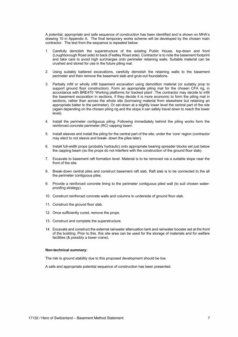
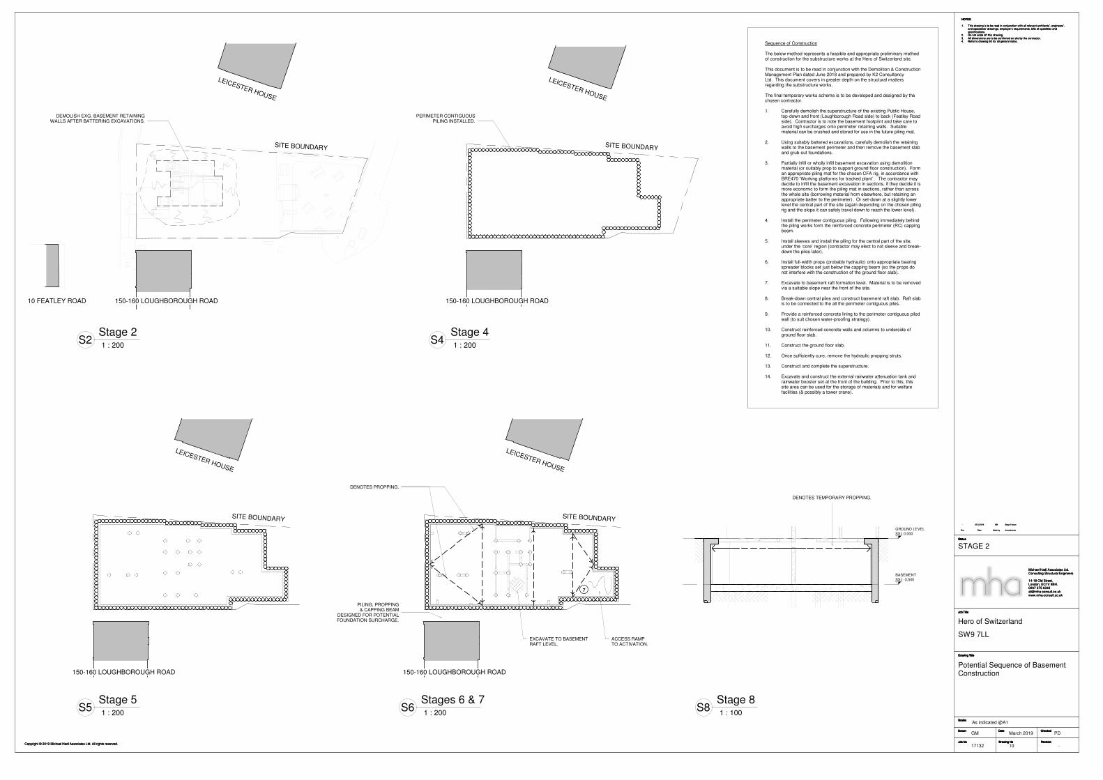
A potential, appropriate and safe sequence of construction has been identified and is shown on MHA’s
drawing 10 in Appendix A. The final temporary works scheme will be developed by the chosen main
contractor. The text from the sequence is repeated below:
1. Carefully demolish the superstructure of the existing Public House, top-down and front
(Loughborough Road side) to back (Featley Road side). Contractor is to note the basement footprint
and take care to avoid high surcharges onto perimeter retaining walls. Suitable material can be
crushed and stored for use in the future piling mat.
2. Using suitably battered excavations, carefully demolish the retaining walls to the basement
perimeter and then remove the basement slab and grub-out foundations.
3. Partially infill or wholly infill basement excavation using demolition material (or suitably prop to
support ground floor construction). Form an appropriate piling mat for the chosen CFA rig, in
accordance with BRE470 ‘Working platforms for tracked plant’. The contractor may decide to infill
the basement excavation in sections, if they decide it is more economic to form the piling mat in
sections, rather than across the whole site (borrowing material from elsewhere but retaining an
appropriate batter to the perimeter). Or set-down at a slightly lower level the central part of the site
(again depending on the chosen piling rig and the slope it can safely travel down to reach the lower
level).
4. Install the perimeter contiguous piling. Following immediately behind the piling works form the
reinforced concrete perimeter (RC) capping beam.
5. Install sleeves and install the piling for the central part of the site, under the ‘core’ region (contractor
may elect to not sleeve and break- down the piles later).
6. Install full-width props (probably hydraulic) onto appropriate bearing spreader blocks set just below
the capping beam (so the props do not interfere with the construction of the ground floor slab).
7. Excavate to basement raft formation level. Material is to be removed via a suitable slope near the
front of the site.
8. Break-down central piles and construct basement raft slab. Raft slab is to be connected to the all
the perimeter contiguous piles.
9. Provide a reinforced concrete lining to the perimeter contiguous piled wall (to suit chosen water-
proofing strategy).
10. Construct reinforced concrete walls and columns to underside of ground floor slab.
11. Construct the ground floor slab.
12. Once sufficiently cured, remove the props.
13. Construct and complete the superstructure.
14. Excavate and construct the external rainwater attenuation tank and rainwater booster set at the front
of the building. Prior to this, this site area can be used for the storage of materials and for welfare
facilities (& possibly a tower crane).
Non-technical summary:
The risk to ground stability due to this proposed development should be low.
A safe and appropriate potential sequence of construction has been presented.

17132 / Hero of Switzerland – Basement Method Statement 8
9.0 (e) Demonstration of how cumulative effects have been considered
There are no known existing basements in the vicinity of the site, thus cumulative effects are deemed to
be insignificant.
In terms of groundwater flow, Arup’s Residential Basement Study, Report of Findings, dated April 2016,
for Lambeth states ‘A solitary, isolated basement which intersects the groundwater table is unlikely to affect the groundwater flows in the wider area: the water will simply flow around the obstruction. The effects on water level are likely to be small and less significant than seasonal or other existing variations in the groundwater table.’
The hydrogeological assessment in Appendix E of Soil Consultant Ltd’s report (contained in Appendix
B) states ‘Typically, if the system were to be modelled, and if the basement fully penetrated the sand and gravel aquifer, the rise in groundwater level might be expected to be no more than perhaps 0.4 m on the upstream edge. Since the proposed basement extends only a very small distance below the water table (relative to the full saturated thickness) this assumed rise will be a considerable over-estimate. There are no basements upstream of the proposed basement at the Hero of Switzerland. Hence, even if there was to be a change in groundwater level there is no basement to be affected.’
Non-technical summary:
The cumulative effects of multiple adjacent basements are not applicable, as there are no known
basements in the vicinity.
It should also be noted that an existing basement exists on the site, it is just being enlarged.

17132 / Hero of Switzerland – Basement Method Statement 9
Appendix A – Potential Sequence of Basement Construction MHA’s drawing 10
SITE BOUNDARY
LEICESTER HOUSE
150-160 LOUGHBOROUGH ROAD
DEMOLISH EXG. BASEMENT RETAINING WALLS AFTER BATTERING EXCAVATIONS.
10 FEATLEY ROAD
SITE BOUNDARY
PERIMETER CONTIGUOUS PILING INSTALLED.
LEICESTER HOUSE
150-160 LOUGHBOROUGH ROAD
SITE BOUNDARY
LEICESTER HOUSE
150-160 LOUGHBOROUGH ROAD
SITE BOUNDARY
7
DENOTES PROPPING.
EXCAVATE TO BASEMENT RAFT LEVEL.
LEICESTER HOUSE
150-160 LOUGHBOROUGH ROAD
PILING, PROPPING & CAPPING BEAM
DESIGNED FOR POTENTIAL FOUNDATION SURCHARGE.
ACCESS RAMP TO ACTIVATION.
SSL 0,000GROUND LEVEL
SSL -3,500BASEMENT
DENOTES TEMPORARY PROPPING.
Status
Drawing No
Date
Drawing Title
Job Title
Checked
RevisionJob No
Scales
Drawn
Status
Drawing No
Date
Drawing Title
Job Title
Checked
RevisionJob No
Scales
Drawn
Copyright © 2019 Michael Hadi Associates Ltd. All rights reserved.
NOTES
1. This drawing is to be read in conjunction with all relevant architects’, engineers’, and specialists’ drawings, employer’s requirements, bills of quantities and specifications.
2. Do not scale off this drawing.3. All dimensions are to be confirmed on site by the contractor.4. Refer to drawing 80 for all general notes.
Michael Hadi Associates Ltd.Consulting Structural Engineers
14-18 Old Street,London, EC1V 9BH.0207 375 [email protected]
As indicated @A1
-
Hero of Switzerland
GM PD
17132 10
Potential Sequence of BasementConstruction
STAGE 2
March 2019
SW9 7LL
Status
Drawing No
Date
Drawing Title
Job Title
Checked
RevisionJob No
Scales
Drawn
Status
Drawing No
Date
Drawing Title
Job Title
Checked
RevisionJob No
Scales
Drawn
Copyright © 2019 Michael Hadi Associates Ltd. All rights reserved.
NOTES
1. This drawing is to be read in conjunction with all relevant architects’, engineers’, and specialists’ drawings, employer’s requirements, bills of quantities and specifications.
2. Do not scale off this drawing.3. All dimensions are to be confirmed on site by the contractor.4. Refer to drawing 80 for all general notes.
Michael Hadi Associates Ltd.Consulting Structural Engineers
14-18 Old Street,London, EC1V 9BH.0207 375 [email protected]
As indicated @A1
-
Hero of Switzerland
GM PD
17132 10
Potential Sequence of BasementConstruction
STAGE 2
March 2019
SW9 7LL
1 : 200
Stage 2S2
1 : 200
Stage 4S4
1 : 200
Stage 5S5
1 : 200
Stages 6 & 7S6
1 : 100
Stage 8S8
Sequence of Construction
The below method represents a feasible and appropriate preliminary method of construction for the substructure works at the Hero of Switzerland site.
This document is to be read in conjunction with the Demolition & Construction Management Plan dated June 2018 and prepared by K2 Consultancy Ltd. This document covers in greater depth on the structural matters regarding the substructure works.
The final temporary works scheme is to be developed and designed by the chosen contractor.
1. Carefully demolish the superstructure of the existing Public House, top-down and front (Loughborough Road side) to back (Featley Road side). Contractor is to note the basement footprint and take care to avoid high surcharges onto perimeter retaining walls. Suitable material can be crushed and stored for use in the future piling mat.
2. Using suitably battered excavations, carefully demolish the retaining walls to the basement perimeter and then remove the basement slab and grub-out foundations.
3. Partially infill or wholly infill basement excavation using demolition material (or suitably prop to support ground floor construction). Form an appropriate piling mat for the chosen CFA rig, in accordance with BRE470 ‘Working platforms for tracked plant’ . The contractor may decide to infill the basement excavation in sections, if they decide it is more economic to form the piling mat in sections, rather than across the whole site (borrowing material from elsewhere, but retaining an appropriate batter to the perimeter). Or set-down at a slightly lower level the central part of the site (again depending on the chosen piling rig and the slope it can safely travel down to reach the lower level).
4. Install the perimeter contiguous piling. Following immediately behind the piling works form the reinforced concrete perimeter (RC) capping beam.
5. Install sleeves and install the piling for the central part of the site, under the ‘core’ region (contractor may elect to not sleeve and break-down the piles later).
6. Install full-width props (probably hydraulic) onto appropriate bearing spreader blocks set just below the capping beam (so the props do not interfere with the construction of the ground floor slab).
7. Excavate to basement raft formation level. Material is to be removed via a suitable slope near the front of the site.
8. Break-down central piles and construct basement raft slab. Raft slab is to be connected to the all the perimeter contiguous piles.
9. Provide a reinforced concrete lining to the perimeter contiguous piled wall (to suit chosen water-proofing strategy).
10. Construct reinforced concrete walls and columns to underside of ground floor slab.
11. Construct the ground floor slab.
12. Once sufficiently cure, remove the hydraulic propping struts.
13. Construct and complete the superstructure.
14. Excavate and construct the external rainwater attenuation tank and rainwater booster set at the front of the building. Prior to this, this site area can be used for the storage of materials and for welfare facilities (& possibly a tower crane).
Rev Date Made by Amendments
- 22.03.2019 GM Stage 2 Issue
Rev Date Made by Amendments
- 22.03.2019 GM Stage 2 Issue
Rev Date Made by Amendments
- 22.03.2019 GM Stage 2 Issue

17132 / Hero of Switzerland – Basement Method Statement 10
Appendix B – Extracts from Soil Consultant’s site investigation report, dated September 2018 76 pages, including appendices
Head Office Chiltern House, Earl Howe Road Holmer Green, High Wycombe Buckinghamshire HP15 6QT t: 01494 712 494 e: [email protected] w: www.soilconsultants.co.uk
Harwich Office Haven House, Albemarle Street Harwich, Essex CO12 3HL t: 01255 241639 e: [email protected]
Registered in England No 1814762 VAT No 491 8249 15
Cardiff Office 23 Romilly Road Cardiff CF5 1FH t: 02920 403575 e: [email protected]
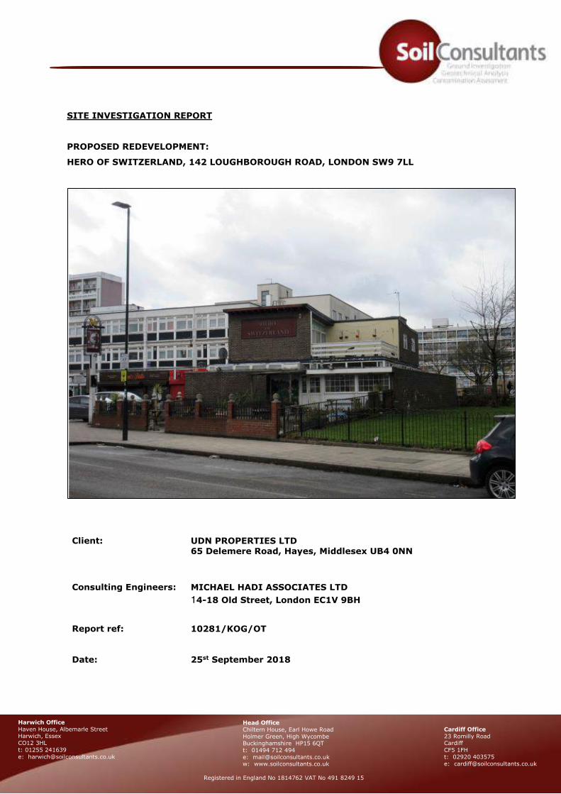
SITE INVESTIGATION REPORT
PROPOSED REDEVELOPMENT:
HERO OF SWITZERLAND, 142 LOUGHBOROUGH ROAD, LONDON SW9 7LL
Client:
UDN PROPERTIES LTD 65 Delemere Road, Hayes, Middlesex UB4 0NN
Consulting Engineers:
MICHAEL HADI ASSOCIATES LTD
14-18 Old Street, London EC1V 9BH
Report ref: 10281/KOG/OT
Date: 25st September 2018

10281/KOG/OT Site Investigation Report – Hero of Switzerland, 142 Loughborough Road, London SW9 7LL
UDN Properties Ltd Michael Hadi Associates Ltd
25st September 2018 (Rev 0)
SITE INVESTIGATION REPORT
PROPOSED REDEVELOPMENT:
HERO OF SWITZERLAND, 142 LOUGHBOROUGH ROAD, LONDON SW9 7LL
DOCUMENT ISSUE STATUS:
Issue Date Description Author Checked/approved
Rev 0 25/09/18 First issue
Keith Gibbs
BSc, MSc, FGS
Opher Tolkovsky
BSc, MSC, DIC, FGS, CGeol
Alan Watson
BSc [Eng] CEnv CEng MICE
Soil Consultants Ltd (SCL) has prepared this Report for the Client in accordance with the Terms of Appointment under which our services were performed. No other warranty, expressed or implied, is made as to the professional advice included in this Report or any other services provided by us. This Report may not be relied upon by any other party without the prior and express written agreement of SCL.

10281/KOG/OT Site Investigation Report – Hero of Switzerland, 142 Loughborough Road, London SW9 7LL
UDN Properties Ltd Michael Hadi Associates Ltd
25st September 2018 (Rev 0)
TABLE OF CONTENTS
1.0 Introduction ..................................................................................................................... 1 2.0 Site description ................................................................................................................. 2 3.0 Phase 1 Preliminary Risk Assessment (Desk Study) ............................................................... 3
3.1 Review of historical information ....................................................................................... 3 3.2 Database information ..................................................................................................... 5 3.3 Other information .......................................................................................................... 7 3.4 Walk-over survey .......................................................................................................... 8 3.5 Potential pollution linkages and Initial Conceptual Site Model .............................................. 8 3.6 Recommendations for intrusive investigation .................................................................. 11
4.0 Exploratory work and laboratory testing ............................................................................. 12 4.1 Rotary auger borehole.................................................................................................. 12 4.2 Trial pits ..................................................................................................................... 12 4.3 Groundwater and gas monitoring ................................................................................... 12 4.4 Geotechnical laboratory testing ..................................................................................... 12 4.5 Chemical and contamination testing ............................................................................... 12
5.0 Ground conditions ........................................................................................................... 13 5.1 Made ground ............................................................................................................... 13 5.2 Taplow Gravel ............................................................................................................. 13 5.3 London Clay Formation ................................................................................................. 13 5.4 Groundwater ............................................................................................................... 14 5.5 Existing foundations ..................................................................................................... 14 5.6 Environmental observations .......................................................................................... 14
6.0 Geotechnical assessment ................................................................................................. 15 6.1 Basement excavation and retaining wall ......................................................................... 15 6.2 Piled foundations ......................................................................................................... 16 6.5 Foundation concrete .................................................................................................... 18
7.0 Basement impact assessment – land stability ..................................................................... 19 7.1 Stage 1 - screening ..................................................................................................... 19 7.2 Stage 2 – scoping ........................................................................................................ 21 7.3 Stage 3 – site investigation ........................................................................................... 22 7.4 Stage 4 – impact assessment ........................................................................................ 22 7.5 Conclusions ................................................................................................................ 23
8.0 Environmental assessment ............................................................................................... 24 8.1 Environmental setting and context ................................................................................. 24 8.2 Contamination sources and testing ................................................................................ 24 8.3 Ground gas/vapour monitoring ...................................................................................... 25 8.4 Disposal of excavated soils ........................................................................................... 26 8.5 Unexploded ordnance risks ........................................................................................... 26 8.6 Refined Conceptual Site Model ...................................................................................... 27
9.0 Additional investigation .................................................................................................... 28
General Information, Limitations and Exception

10281/KOG/OT Site Investigation Report – Hero of Switzerland, 142 Loughborough Road, London SW9 7LL
UDN Properties Ltd Michael Hadi Associates Ltd
25st September 2018 (Rev 0)
APPENDIX A
Fieldwork, in-situ testing and monitoring
Foreword Borehole record Standard Penetration Test results SPT hammer calibration certificate Trial pit record Groundwater and gas monitoring results
Laboratory testing
Index property testing Plasticity chart Unconsolidated undrained triaxial test results (QUT) Particle size distribution tests
Ground profiles
Plot of SPT ‘N’ value and undrained cohesion versus depth
Contamination and chemical testing
Foreword General soil suite WAC test results Sulphate/pH suite
Plans, drawings & photographs
Site photographs Proposed development plans and sections Site Plan Location Maps
APPENDIX B
GroundSure historical maps (Ref SCL-5320272) GroundSure EnviroInsight Report (Ref SCL-5320270) GroundSure GeoInsight Report (Ref SCL-5320271)
APPENDIX C
Lambeth Council Contaminated land and historical land use search report
APPENDIX D
GroundSure Preliminary Unexploded Ordnance Risk Report (Ref SCL–532073) RPS UXO Classification Email Report dated 24 September 2018
APPENDIX E
Stephen Buss Environmental Consulting Ltd, Hero of Switzerland, 142 Loughborough Road, Basement Impact Assessment. Report ref. 2018-003-050-001, September 2018

10281/KOG/OT Site Investigation Report – Hero of Switzerland, 142 Loughborough Road, London SW9 7LL Page 1
UDN Properties Ltd Michael Hadi Associates Ltd
25st September 2018 (Rev 0)
1.0 INTRODUCTION
The proposed redevelopment of the site will involve demolition of the existing public house and the
construction of a new 14 storey apartment building incorporating a full footprint single level basement. In
connection with the proposed works, Soil Consultants Ltd (SCL) were commissioned by Michael Hadi
Associates Ltd (MHA) on behalf of the Client UDN Properties Ltd, to carry out a site investigation to include
the following elements:
Phase 1 Preliminary Risk Assessment (PRA) including initial Conceptual Site Model (CSM)
Phase 2 intrusive investigation
Provision of advice on foundations, basement excavation, retaining walls and floor slab
Contamination risk assessment and refine Conceptual Site Model (CSM)
Basement Impact Assessment (BIA) – SCL have provided the Land stability element of the BIA.
We commissioned a hydrogeological report from Environmental Consulting Ltd and this is included
as an Appendix to this report.
10281/KOG/OT Site Investigation Report – Hero of Switzerland, 142 Loughborough Road, London SW9 7LL Page 2
UDN Properties Ltd Michael Hadi Associates Ltd
25st September 2018 (Rev 0)
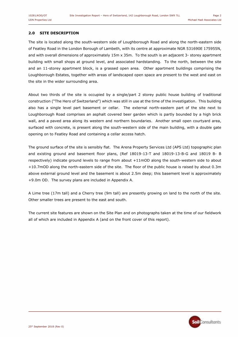
2.0 SITE DESCRIPTION
The site is located along the south-western side of Loughborough Road and along the north-eastern side
of Featley Road in the London Borough of Lambeth, with its centre at approximate NGR 531690E 175955N,
and with overall dimensions of approximately 15m x 35m. To the south is an adjacent 3- storey apartment
building with small shops at ground level, and associated hardstanding. To the north, between the site
and an 11-storey apartment block, is a grassed open area. Other apartment buildings comprising the
Loughborough Estates, together with areas of landscaped open space are present to the west and east on
the site in the wider surrounding area.
About two thirds of the site is occupied by a single/part 2 storey public house building of traditional
construction (“The Hero of Switzerland”) which was still in use at the time of the investigation. This building
also has a single level part basement or cellar. The external north-eastern part of the site next to
Loughborough Road comprises an asphalt covered beer garden which is partly bounded by a high brick
wall, and a paved area along its western and northern boundaries. Another small open courtyard area,
surfaced with concrete, is present along the south-western side of the main building, with a double gate
opening on to Featley Road and containing a cellar access hatch.
The ground surface of the site is sensibly flat. The Arena Property Services Ltd (APS Ltd) topographic plan
and existing ground and basement floor plans, (Ref 18019-13-T and 18019-13-B-G and 18019 B- B
respectively) indicate ground levels to range from about +11mOD along the south-western side to about
+10.7mOD along the north-eastern side of the site. The floor of the public house is raised by about 0.3m
above external ground level and the basement is about 2.5m deep; this basement level is approximately
+9.0m OD. The survey plans are included in Appendix A.
A Lime tree (17m tall) and a Cherry tree (9m tall) are presently growing on land to the north of the site.
Other smaller trees are present to the east and south.
The current site features are shown on the Site Plan and on photographs taken at the time of our fieldwork
all of which are included in Appendix A (and on the front cover of this report).
10281/KOG/OT Site Investigation Report – Hero of Switzerland, 142 Loughborough Road, London SW9 7LL Page 3
UDN Properties Ltd Michael Hadi Associates Ltd
25st September 2018 (Rev 0)
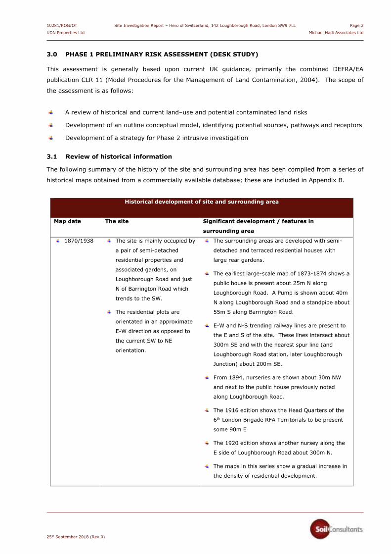
3.0 PHASE 1 PRELIMINARY RISK ASSESSMENT (DESK STUDY)
This assessment is generally based upon current UK guidance, primarily the combined DEFRA/EA
publication CLR 11 (Model Procedures for the Management of Land Contamination, 2004). The scope of
the assessment is as follows:
A review of historical and current land–use and potential contaminated land risks
Development of an outline conceptual model, identifying potential sources, pathways and receptors
Development of a strategy for Phase 2 intrusive investigation
3.1 Review of historical information
The following summary of the history of the site and surrounding area has been compiled from a series of
historical maps obtained from a commercially available database; these are included in Appendix B.
Historical development of site and surrounding area
Map date The site Significant development / features in
surrounding area
1870/1938 The site is mainly occupied by
a pair of semi-detached
residential properties and
associated gardens, on
Loughborough Road and just
N of Barrington Road which
trends to the SW.
The residential plots are
orientated in an approximate
E-W direction as opposed to
the current SW to NE
orientation.
The surrounding areas are developed with semi-
detached and terraced residential houses with
large rear gardens.
The earliest large-scale map of 1873-1874 shows a
public house is present about 25m N along
Loughborough Road. A Pump is shown about 40m
N along Loughborough Road and a standpipe about
55m S along Barrington Road.
E-W and N-S trending railway lines are present to
the E and S of the site. These lines intersect about
300m SE and with the nearest spur line (and
Loughborough Road station, later Loughborough
Junction) about 200m SE.
From 1894, nurseries are shown about 30m NW
and next to the public house previously noted
along Loughborough Road.
The 1916 edition shows the Head Quarters of the
6th London Brigade RFA Territorials to be present
some 90m E
The 1920 edition shows another nursey along the
E side of Loughborough Road about 300m N.
The maps in this series show a gradual increase in
the density of residential development.

10281/KOG/OT Site Investigation Report – Hero of Switzerland, 142 Loughborough Road, London SW9 7LL Page 4
UDN Properties Ltd Michael Hadi Associates Ltd
25st September 2018 (Rev 0)
Historical development of site and surrounding area
Map date The site Significant development / features in
surrounding area
1948 The site is shown as clear of
any development with all
traces of former houses now
absent. This absence may be
indicative of WW2 bomb
damage.
The immediate area around the junction of
Barrington Road and Loughborough Road is shown
as devoid of any structures which we attribute to
demolition following likely bomb damage in WW2
(see later discussion).
1950 - 1954 The site comprises gardens of
new houses constructed along
Barrington Road Gardens.
A Ruin (previously noted former public house) is
shown 20m to 25m N which is surrounded by
undeveloped open space. Similar open space is
shown to the S of Barrington Road Gardens and to
the SW of Angell Road.
New housing layouts are shown to the E and S.
Electricity substation is shown 170m E.
1958-1968 The site is again shown as
clear of any development with
the former houses along
Barrington Road Close now
absent.
Featley Road has been constructed and a block of
terraced houses is shown immediately to the S of
the site.
A new high-rise apartment building (Leicester
House) is shown about 10m N of the site. Other
similar tower blocks are shown to the N, W and S.
New terraced houses have been built along the NE
side of Loughborough Road.
Works identified 150m E of the site.
1973 to
present
The current site outline is
now present, with the
majority of the site occupied
by a public house building
and associated external
areas.
The surrounding areas have remained largely
unchanged and remain predominantly residential
in character.
An electricity substation is shown 30m S of the site
adjacent to a Child Health Centre (building
redeveloped in early 2000’s and substation not
currently observed from street).
Council Yard identified 100m E of the site.

10281/KOG/OT Site Investigation Report – Hero of Switzerland, 142 Loughborough Road, London SW9 7LL Page 5
UDN Properties Ltd Michael Hadi Associates Ltd
25st September 2018 (Rev 0)
3.2 Database information
The database report includes information of local activities encompassing a range of subjects related to
land use, pollution, and geological/hydrological conditions. Our assessment of contaminative uses and
other environmental issues relevant to the site and its surroundings is provided below. The full database
report is included as Appendix B and this should be read and understood fully in conjunction with this
summary.
Groundsure EnviroInsight Report (Ref SCL-5320270)
Historical Industrial Sites
Potentially contaminated uses (within 250m): Various nurseries are identified in the local area with
the nearest record for the 1894 map on-site. Our map review (see above) has, however, noted the
site to straddle two residential properties at this time. In this review the nearest nurseries were
identified about 20m N. The remaining entries within 250m relate to railway buildings/station.
Historical tank database (within 250m): Unspecified tanks noted 98m NE, 137m N, 178m NE and
196m S.
Historical energy features database (within 250m): Electricity substations noted 28m S, 84m N,
116m SW, 117m NW, 170m NW, 173m E, and 180m NW.
Historical petrol and fuel site database: No data present.
Historical garage and motor vehicle repair database: Nearest 388m W.
Potentially infilled land (within 250m): Nearest 422m S for unspecified heap.
Environmental Permits, Incidents and Registers
Records of Part A(2) and Part B Activities: 225m SE and 405m NW for dry cleaners, 409m SE
Waste oil burning, 429m SE for Petrol service station – Historical permit, 445 SE Herne Hill petrol
station – Current permit. No enforcements for any of these locations.
Records of Category 3 or 4 Radioactive Substances Licences: None.
Records of Licensed Discharge Consents: None within 500m.
Landfill and other Waste Sites
Waste treatment, transfer/disposal sites with 500m: 80m E for scrap yard – historical. 351m SE
for recycling facility – historical.
Records of Environment Agency waste sites within 500m: Nearest 180m E and 244m NE - vehicle
depollution facility, 274m SE for Tenmead Ltd for HCI waste TS and treatment, 461m SE London
Borough of Lambeth for a clinical waste transfer station.

10281/KOG/OT Site Investigation Report – Hero of Switzerland, 142 Loughborough Road, London SW9 7LL Page 6
UDN Properties Ltd Michael Hadi Associates Ltd
25st September 2018 (Rev 0)
Current Land Use
Potentially contaminative uses: 26m S, 94m N, 116m SW, 119m NW, 169m NW, 182m E -
electricity substations. Others notable entries include scrap metal merchants 175m NE, 192m E
and 241m NE, unspecified works or factories 180m E, vehicle repair 221m-234m SE and 237m-
248m NE, Loughborough Junction Rail Station 245m SE. A number of entries probably refer to
office premises and would not therefore be contaminative
Petrol and Fuel sites: 431m SE for Herne Hill Service Station – open.
Hydrogeology and Hydrology
Aquifer within superficial deposits: ‘Secondary A’ (Taplow Gravel).
Aquifer within bedrock deposits: ‘Unproductive’ (London Clay).
Groundwater Abstraction: None within 500m of site, the nearest being 646m E, Thames
groundwater borehole.
Surface Water Features: None identified within 250m.
Potable Water Abstraction: None within 1000m of the site, the nearest being 1976m SW.
Source Protection Zones: The site is not within any source protection zones.
River Quality: No data.
Detailed River Network: No data.
Flooding
No Zone 2 or 3 floodplains or flood defences within 250m of site.
Risk of flooding: Very low.
Groundwater Flooding Susceptibility Areas: Clearwater flooding of superficial deposits with potential
at surface (moderate confidence).
Designated Environmentally Sensitive Areas: None

10281/KOG/OT Site Investigation Report – Hero of Switzerland, 142 Loughborough Road, London SW9 7LL Page 7
UDN Properties Ltd Michael Hadi Associates Ltd
25st September 2018 (Rev 0)
Groundsure Geo Insight Report (Ref SCL-5320271)
Geology
Artificial /Made Ground: No records.
Superficial Deposits/Drift Geology: Taplow Gravel (high to very high permeability) on site.
Bedrock/Solid Geology: London Clay (very low to low permeability).
Radon: The property is not in a Radon Affected Area (<1% of properties are above action level) -
no protective measures required.
Historical Surface/Underground Workings: No records.
Mining, Extraction & Natural Cavities: Single record for chalk mining 903m NE (considered not
relevant to site). No other entries.
Natural Ground Subsidence: Very low to negligible risks for all categories where identified.
Borehole Records Map: 16no within 250m of site.
Estimated Soil Background Chemistry: No data
Railways and Tunnels: Historical tunnels 188m E and 224m E. Nearest Active railways 191m E.
3.3 Other information
Local Authority search
The London Borough of Lambeth hold a database of historical land uses which is not included in the
Groundsure database. A report was commissioned from Lambeth Council and this is incorporated as
Appendix C.
Their report concludes that their database search for the site and the surrounding area has found no records
of contamination. They also have no enforcement concerns relating to Part IIA of the Environmental
Protection Act 1990 and therefore do not intend to carry out any investigation under this legislation.
The report goes on to list various current and historical records for activities around the site. These are
broadly consistent with those outlined in the Groundsure review above.
Groundsure Unexploded Ordnance risk assessment reports
The preliminary Groundsure UXO threat assessment report (Ref SCL-5320271] noted a High Risk
classification for WWS2 related unexploded ordnance at the site. A subsequent review by RPS confirmed
a lower level ALARP (as low as reasonably practicable) classification with an allowance for a UXO clearance
engineer to be on call and to attend site if any suspicious objects were discovered during intrusive works.
Both the Groundsure and RPS reports are included in Appendix D.

10281/KOG/OT Site Investigation Report – Hero of Switzerland, 142 Loughborough Road, London SW9 7LL Page 8
UDN Properties Ltd Michael Hadi Associates Ltd
25st September 2018 (Rev 0)
3.4 Walk-over survey
A site walk-over survey was undertaken on 23rd August 2018. A description of the general features of the
site and the topography is provided in Section 2.0 above. From inspection of visible and accessible areas,
a summary of specific features relevant to the land quality assessment is as follows:
Feature
Commentary
Electricity substations and
transformers
None identified in proximity to site although the desk study review has noted a
substation 28m S
Fuel storage tanks None on site
Fuel interceptors None on site
General chemical
storage/waste
None noted in external areas
Storage contained in basement/cellar consistent with existing site usage as public
house
Invasive species None noted
Evidence of gas protection None noted
Surface water
contamination
No surface water present
Waste storage Site is reasonably tidy and in use as Public house
ACMs None noted but may be present in rooting/flooring and as lagging around pipes in
basement
Anecdotal information During fieldwork the pub landlord informed that the cellar has been known to
slightly flood in the past, though this flooding did not wholly coincide with
increased rainfall.
3.5 Potential pollution linkages and Initial Conceptual Site Model
The information in the preceding sections has been used to undertake the Preliminary Risk Assessment and
to compile the Initial Site Conceptual Model below. The assessment follows as risk-based approach, with
the potential risks determined qualitatively using the ‘source-pathway-receptor’ linkage concept; a risk of
harm may only exist where a plausible linkage is present. The assessment has been formulated based on
the following table:
Consequences
Severe Medium Mild Minor
Pro
bab
ilit
y
High likelihood Very high risk
High risk Moderate risk Moderate/low risk
Likely High risk
Moderate risk Moderate/low risk Low risk
Low likelihood Moderate risk
Moderate/low risk Low risk Very low risk
Unlikely Moderate/low risk
Low risk Very low risk Very low risk

10281/KOG/OT Site Investigation Report – Hero of Switzerland, 142 Loughborough Road, London SW9 7LL Page 9
UDN Properties Ltd Michael Hadi Associates Ltd
25st September 2018 (Rev 0)
Definitions of the risks are summarised as follows:
Very high: high probability that severe harm could occur, or there is evidence that it is currently
occurring. If realised, the risk could result in substantial liability. Urgent investigation/remediation
High: harm is likely to occur, realisation is likely to present substantial liability. Urgent
investigation required. Remedial works may be required in short-term, will be in long-term
Moderate: possible that harm could arise, but unlikely to be severe. Investigation normally
required to clarify risk and liability. Remedial works may be necessary in long-term
Low: possible that harm could occur, but this would at worst be mild
Very low: low possibility of harm, unlikely to be severe
The assessment has been carried out by identifying and evaluating the potential sources of contamination,
the potential receptors and the plausible pathways for contamination migration are summarised as follows:
Potential sources of contamination
Potential Source
Element/Compound potential
On site
Building built pre-2000 Asbestos
Made ground
Commercial public house usage
Hydrocarbons (TPH, PAH)
Heavy metals/semi metals
Inorganic or organic chemicals
Ground gas and VOCs
Off site
No significant potential sources identified
apart from historical record of nearby
substation
No significant risk of cross contamination
identified apart from possible relict PCB
contamination
Potential receptors
In the context of the proposed development, the following potential receptors have been identified:
Human health: inhabitants/users of building, construction workers, adjacent site users
Controlled waters: Secondary aquifer of the Taplow Gravel underlain by Unproductive London Clay.
The site is not located within a source protection zone and there are no relevant surface or
groundwater within a relevant distance of the site. The site is assessed as being of Low to
medium environmental sensitivity
Building fabric and services: buried foundations, basement wall, potable water pipes

10281/KOG/OT Site Investigation Report – Hero of Switzerland, 142 Loughborough Road, London SW9 7LL Page 10
UDN Properties Ltd Michael Hadi Associates Ltd
25st September 2018 (Rev 0)
Plausible pathways
Ingestion of soil, dust or water
Inhalation of dust, gas or vapours
Direct physical contact with contaminated soil/water
Vertical and lateral migration of contamination including leaching
Chemical attack of building infrastructure, including water supply pipes
Migration of ground gas/vapour through permeable soils or open pathways
The Initial Conceptual Site Model and an estimate of the risk associated with each potential linkage is shown
in the following table:
Source Pathway Receptor Assessed risk and commentary/justification
On-site:
contaminated soil
Ingestion, contact,
inhalation
End user,
construction
workers and
infrastructure
Low risk: no significant historical potential sources
identified on site and currently, the main potential source
is the anticipated made ground layer. Proposed basement
will remove bulk of made ground with hardstanding
proposed over remaining new beer garden so potential for
direct contact would be eliminated
Leaching from
contaminated soils
and migration in
groundwater
Aquifer and
surface water
Low risk: basement will remove bulk of made ground and
proposed scheme envisages 100% hard cover eliminating
any water infiltration. High permeability secondary
aquifer present above relatively impermeable London Clay
which would provide barrier above any deeper chalk
aquifer
Off-site:
contaminated soil
Lateral migration of
contaminants to site
in groundwater
End user
Low risk: main identified off-site sources are historical
commercial/industrial activities in the general area (none
identified in immediate vicinity of the site); however,
these were largely redeveloped into residential use
following WW2. Historical record of substation nearby.
On-site and off-
site: ground gas
and vapours
Lateral and vertical
migration of
gas/vapour
End-user and
buildings
Low risk: no significant potential gas/vapour sources
identified. The site is not in a radon affected area
The overall risk rating for the site is assessed as being Low to moderate.

10281/KOG/OT Site Investigation Report – Hero of Switzerland, 142 Loughborough Road, London SW9 7LL Page 11
UDN Properties Ltd Michael Hadi Associates Ltd
25st September 2018 (Rev 0)
3.6 Recommendations for intrusive investigation
The Initial Conceptual Site Model identified potential pollution linkages resulting in the overall assessed risk
rating of moderate. The following programme of intrusive investigation is recommended:
Suitable intrusive investigation to confirm the ground sequence, allow soil sampling and the
installation of monitoring pipes
No specific contamination sources were identified by the PRA so the investigation should provide
general suite of analysis with possible targeted PCB analysis in area closest to the location of the
substation noted in desk study review to the south of the site
Soil samples should be recovered where relevant and be analysed for a range of general
contaminants to include petroleum hydrocarbons, PAHs and asbestos screening
Groundwater and gas monitoring
The Initial Conceptual Site Model should then be revised to include complete pollution linkages and outline
mitigation/remedial measures should be identified, together with any requirements for additional
investigation.

10281/KOG/OT Site Investigation Report – Hero of Switzerland, 142 Loughborough Road, London SW9 7LL Page 12
UDN Properties Ltd Michael Hadi Associates Ltd
25st September 2018 (Rev 0)
4.0 EXPLORATORY WORK AND LABORATORY TESTING
The scope of the initial phase of ground investigation was devised by the structural engineer, and it was
carried out on 23rd August 2018. At this time only a limited area was available for investigation due to the
continued commercial operation of the public house; a further deep borehole is proposed at a later stage
to provide full pile design information. The investigation comprised the following elements.
4.1 Rotary auger borehole
A single borehole was carried out in the beer garden area using a tracked auger equipment under the
supervision of an experienced engineer. In-situ testing was carried out at appropriate intervals and
representative samples, both disturbed and relatively undisturbed U100s were taken for geotechnical and
environmental testing. PID headspace testing was also carried out. The borehole was taken to 12m depth
and a monitoring pipe was installed in the borehole to 6m depth upon completion. The hammer Energy
Ratio (Er) for the equipment used was 78%; the relevant test certificate is appended.
4.2 Trial pits
Two trial pits were undertaken using hand tools. TP1 which was positioned in the existing basement was
terminated when groundwater inflow occurred at shallow depth. TP2 was excavated along the
external/northern side of the pubic house.
4.3 Groundwater and gas monitoring
Water and gas monitoring was carried out on one occasion following completion of the site works on 4th
September 2018.
4.4 Geotechnical laboratory testing
The following geotechnical laboratory testing was completed:
Index properties tests (Atterberg Limits)
Particle size distribution tests
Unconsolidated, undrained triaxial tests
4.5 Chemical and contamination testing
Selected soil samples were delivered to a specialist laboratory (DETS Ltd) and the following testing was
carried out:
General soil suite - 3no samples
Asbestos screening - 3no samples
Waste Acceptance Criteria (WAC) - 1no sample
Soluble sulphate/sulphur/pH analyses - 8no samples
The engineering borehole and trial pit logs and the laboratory testing results are included in Appendix A
10281/KOG/OT Site Investigation Report – Hero of Switzerland, 142 Loughborough Road, London SW9 7LL Page 13
UDN Properties Ltd Michael Hadi Associates Ltd
25st September 2018 (Rev 0)
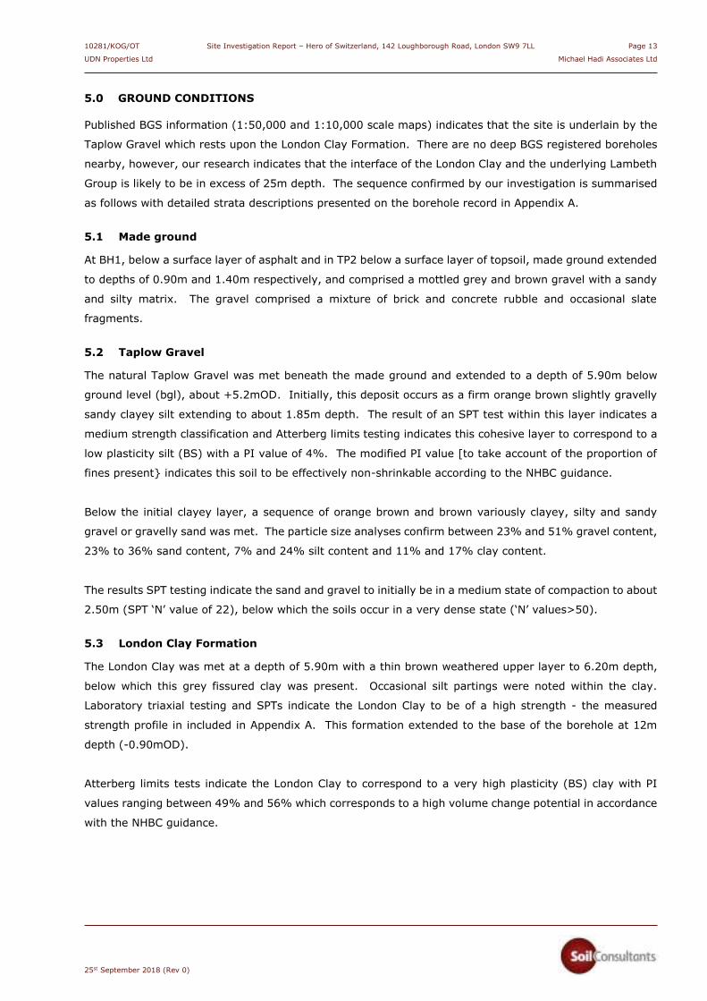
5.0 GROUND CONDITIONS
Published BGS information (1:50,000 and 1:10,000 scale maps) indicates that the site is underlain by the
Taplow Gravel which rests upon the London Clay Formation. There are no deep BGS registered boreholes
nearby, however, our research indicates that the interface of the London Clay and the underlying Lambeth
Group is likely to be in excess of 25m depth. The sequence confirmed by our investigation is summarised
as follows with detailed strata descriptions presented on the borehole record in Appendix A.
5.1 Made ground
At BH1, below a surface layer of asphalt and in TP2 below a surface layer of topsoil, made ground extended
to depths of 0.90m and 1.40m respectively, and comprised a mottled grey and brown gravel with a sandy
and silty matrix. The gravel comprised a mixture of brick and concrete rubble and occasional slate
fragments.
5.2 Taplow Gravel
The natural Taplow Gravel was met beneath the made ground and extended to a depth of 5.90m below
ground level (bgl), about +5.2mOD. Initially, this deposit occurs as a firm orange brown slightly gravelly
sandy clayey silt extending to about 1.85m depth. The result of an SPT test within this layer indicates a
medium strength classification and Atterberg limits testing indicates this cohesive layer to correspond to a
low plasticity silt (BS) with a PI value of 4%. The modified PI value [to take account of the proportion of
fines present} indicates this soil to be effectively non-shrinkable according to the NHBC guidance.
Below the initial clayey layer, a sequence of orange brown and brown variously clayey, silty and sandy
gravel or gravelly sand was met. The particle size analyses confirm between 23% and 51% gravel content,
23% to 36% sand content, 7% and 24% silt content and 11% and 17% clay content.
The results SPT testing indicate the sand and gravel to initially be in a medium state of compaction to about
2.50m (SPT ‘N’ value of 22), below which the soils occur in a very dense state (‘N’ values>50).
5.3 London Clay Formation
The London Clay was met at a depth of 5.90m with a thin brown weathered upper layer to 6.20m depth,
below which this grey fissured clay was present. Occasional silt partings were noted within the clay.
Laboratory triaxial testing and SPTs indicate the London Clay to be of a high strength - the measured
strength profile in included in Appendix A. This formation extended to the base of the borehole at 12m
depth (-0.90mOD).
Atterberg limits tests indicate the London Clay to correspond to a very high plasticity (BS) clay with PI
values ranging between 49% and 56% which corresponds to a high volume change potential in accordance
with the NHBC guidance.

10281/KOG/OT Site Investigation Report – Hero of Switzerland, 142 Loughborough Road, London SW9 7LL Page 14
UDN Properties Ltd Michael Hadi Associates Ltd
25st September 2018 (Rev 0)
5.4 Groundwater
In BH1, groundwater was encountered during drilling within the Taplow Gravel at about 4.2m depth, and
a rest level of 3.95m was measured during subsequent monitoring of the standpipe. A water inflow met
during the shallow excavation from basement level of TP1, we attribute to the local occurrence of trapped
water directly below the slab.
Groundwater levels can of course vary seasonally and with prevailing weather conditions.
5.5 Existing foundations
A detailed record of the trial pit is included in Appendix A. A summary of the findings of the internal trial
pits is as follows:
TP ref Location Foundation details
TP1 Basement of existing public house Slab estimated at 300mm to 400mm thick by pilot drilling. Water seepage at 0.05m. Pit not completed
TP 2 Wall along northern side of public house Masonry wall extends to 0.75m depth. Concrete footing underside possibly at 1.40m in dense
gravel (unable to fully confirm depth due to services)
5.6 Environmental observations
No obvious olfactory or visual signs of soil or groundwater contamination were encountered in the
boreholes. PID headspace testing (for VOC concentrations) has been undertaken and no elevated levels
were noted.
10281/KOG/OT Site Investigation Report – Hero of Switzerland, 142 Loughborough Road, London SW9 7LL Page 15
UDN Properties Ltd Michael Hadi Associates Ltd
25st September 2018 (Rev 0)
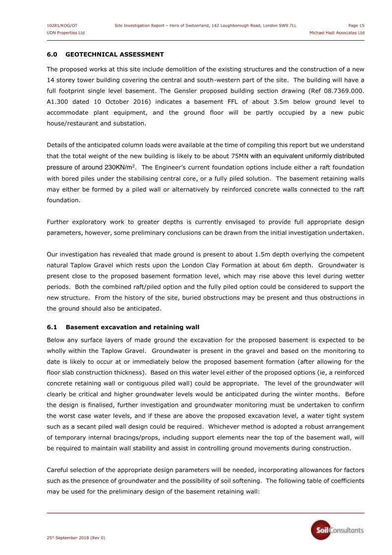
6.0 GEOTECHNICAL ASSESSMENT
The proposed works at this site include demolition of the existing structures and the construction of a new
14 storey tower building covering the central and south-western part of the site. The building will have a
full footprint single level basement. The Gensler proposed building section drawing (Ref 08.7369.000.
A1.300 dated 10 October 2016) indicates a basement FFL of about 3.5m below ground level to
accommodate plant equipment, and the ground floor will be partly occupied by a new pubic
house/restaurant and substation.
Details of the anticipated column loads were available at the time of compiling this report but we understand
that the total weight of the new building is likely to be about 75MN with an equivalent uniformly distributed pressure of around 230KN/m2. The Engineer’s current foundation options include either a raft foundation
with bored piles under the stabilising central core, or a fully piled solution. The basement retaining walls
may either be formed by a piled wall or alternatively by reinforced concrete walls connected to the raft
foundation.
Further exploratory work to greater depths is currently envisaged to provide full appropriate design
parameters, however, some preliminary conclusions can be drawn from the initial investigation undertaken.
Our investigation has revealed that made ground is present to about 1.5m depth overlying the competent
natural Taplow Gravel which rests upon the London Clay Formation at about 6m depth. Groundwater is
present close to the proposed basement formation level, which may rise above this level during wetter
periods. Both the combined raft/piled option and the fully piled option could be considered to support the
new structure. From the history of the site, buried obstructions may be present and thus obstructions in
the ground should also be anticipated.
6.1 Basement excavation and retaining wall
Below any surface layers of made ground the excavation for the proposed basement is expected to be
wholly within the Taplow Gravel. Groundwater is present in the gravel and based on the monitoring to
date is likely to occur at or immediately below the proposed basement formation (after allowing for the
floor slab construction thickness). Based on this water level either of the proposed options (ie, a reinforced
concrete retaining wall or contiguous piled wall) could be appropriate. The level of the groundwater will
clearly be critical and higher groundwater levels would be anticipated during the winter months. Before
the design is finalised, further investigation and groundwater monitoring must be undertaken to confirm
the worst case water levels, and if these are above the proposed excavation level, a water tight system
such as a secant piled wall design could be required. Whichever method is adopted a robust arrangement
of temporary internal bracings/props, including support elements near the top of the basement wall, will
be required to maintain wall stability and assist in controlling ground movements during construction.
Careful selection of the appropriate design parameters will be needed, incorporating allowances for factors
such as the presence of groundwater and the possibility of soil softening. The following table of coefficients
may be used for the preliminary design of the basement retaining wall:

10281/KOG/OT Site Investigation Report – Hero of Switzerland, 142 Loughborough Road, London SW9 7LL Page 16
UDN Properties Ltd Michael Hadi Associates Ltd
25st September 2018 (Rev 0)
Stratum Bulk density
(Mg/m3)
Effective cohesion, c’
(kN/m2)
Effective friction angle, I’
(degrees)
Made ground
1.80 0 22
Taplow Gravel
2.00 0 35
London Clay:
<5m below basement level
>5m below basement level
2.00
2.00
0
5
21
21
Eurocode 7 stipulates that partial material factors must be applied to the best estimates of geotechnical
soil properties during the design stage. The design engineer must ensure that the correct comparisons are
made between Design Actions and Design Resistances after the application of appropriate partial factors.
The determination of appropriate earth pressure coefficients and the pattern of earth pressure distribution
should be carried out by the geotechnical designer; these will depend upon the type/geometry of the wall
and the overall design approach. If a piled perimeter wall is adopted then these piles may of course also
be used to provide vertical load capacity subject to the necessary allowance being made for interaction
effects. We recommend that a specialist contractor is consulted to confirm the most appropriate type of
wall and to provide the final wall design.
6.2 Piled foundations
The final design of piled foundations will need to be informed with data from greater depths than that
currently achieved. For the ground conditions encountered to date, with groundwater being present within
the Taplow Gravel and likely present as minor inflows within the deeper lying London Clay/Lambeth Group,
we consider that CFA piles will present the optimum type.
If piles need to be extended into the Lambeth Group strata then some modification of the pile parameters
or downgrading of the pile capacities may be warranted to mitigate the possible risk of clay softening,
although this should be minimal with well-installed CFA piles. In this situation consideration could be given
to designing the piles to achieve the required capacity wholly within the more uniform London Clay.
A piling specialist must be consulted at an early stage to advise on the most appropriate pile type and to
ultimately provide the final pile design. This should address issues such as the potential clay softening and
the relative performance of the probable clay and sand layers within the Lambeth Group. If pile testing is
undertaken it will be possible to apply lower partial factors, resulting in increased pile resistances, however,
this may not be economical given the relatively small scale of this project.

10281/KOG/OT Site Investigation Report – Hero of Switzerland, 142 Loughborough Road, London SW9 7LL Page 17
UDN Properties Ltd Michael Hadi Associates Ltd
25st September 2018 (Rev 0)
6.3 Basement slab [non-raft] and heave
If a fully piled foundation is to be adopted to support he structural loads, then a conventional basement
floor slab will be constructed. The basement excavation will involve the removal of up to 4m [allowing for
basement slab thickness) of soil below the proposed building footprint, resulting in unloading of about
80kPa. This stress reduction will theoretically result in an element of heave in the London Clay.
The potential long-term effect of this heave in the London Clay as it recovers should be considered during
slab design. The slab could be designed as a fully suspended structure, supported on the main foundations,
and incorporating an effective void beneath to accommodate future heave movement. Assuming a worst-
case situation of the maximum reduction in overburden (up to say 4m) over the maximum basement area
(14m x 20m), preliminary analysis indicates that a total unrestrained heave of between about 20mm to
30mm could occur as a result of the unloading. Approximately 50% of this heave movement is likely to
occur during a typical construction programme, leaving a maximum possible post-construction heave of
10mm to 15mm to be accommodated.
In reality the amount of heave will also be affected by other factors such as the fact that a basement
already exists to about 2.5m depth over part of the site, therefore some unloading of the London Clay
would already have occurred in this area. Also the length of the construction programme and the
restraining effect of the basement slab stiffness and not least the presence of the remaining Taplow Gravel
below the basement slab can all have significant impacts.
The alternative to a fully suspended voided slab would be to use a ground bearing slab which is designed
to withstand potential heave forces/movements. If it is (reasonably) assumed that the relationship
between heave movement and pressure is linear, the maximum heave pressure for an infinitely stiff slab
could therefore be about 35kPa for the fully constrained condition. However, this will not occur in reality
and the heave pressure beneath a more flexible slab will clearly be less (due stress dissipation as the slab
deflects); we anticipate that an ‘average’ stiffness slab would experience heave pressures of the order of
15kPa with heave movements of <10mm.
It will be necessary to consider uplift of the slab due to potential hydrostatic pressures and in this respect
the guidelines incorporated in BS8102:2009 should be followed. The slab design will need to take account
of potential seasonal fluctuations and/or accidental and flood conditions. We recommend that a design
water level at 1m depth below current ground level is adopted for preliminary purposes and this would
result in a hydrostatic uplift pressure of about 25kPa on the basement slab; this design water level may
need to be agreed with the local building control.
6.4 Basement raft foundation
If the layout and configuration of the new loads permit, a reinforced concrete basement raft could be
considered (subject to acceptable stresses/settlements). This would be a significantly more robust
structure than the basement slab and would be designed to effectively distribute the loads over the whole
new basement footprint.

10281/KOG/OT Site Investigation Report – Hero of Switzerland, 142 Loughborough Road, London SW9 7LL Page 18
UDN Properties Ltd Michael Hadi Associates Ltd
25st September 2018 (Rev 0)
Initial calculations indicate at the design pressure the raft foundation would experience a total settlement
of up between 100mm and 150mm. This settlement is likely to be excessive and it is considered that a
hybrid piled-raft foundation will be required to control settlements. The number and configuration of the
piles would be need to be determined following further investigation and finalisation of the loads. A detailed
Ground Movement Analysis (GMA) will probably be required to address potential settlements in detail,
particularly along the site boundaries and to determine soil/structure interactions for the piled raft structural
design.
6.5 Foundation concrete
Low concentrations of water soluble sulphates (2:1 water/soil extract) were measured in selected soil
samples, with slightly alkaline pH values. The results fall into Site Design Class DS-1 of Table C2 given in
BRE Special Digest 1 (2005). We assess the site as having ‘mobile’ groundwater and this would result in
an ACEC Site Class of AC-1.
Consideration should also be given to the potential oxidation of pyritic soils. Following the procedure
recommended in the BRE digest, the amount of oxidisable sulphides is seen to be >0.3% in two of the
samples of London Clay, suggesting that pyrite is probably present. The characteristic value of Total
Potential Sulphate is 1.05%, which equates to Class DS-3 with a resultant classification of ACEC AC-3. If
it is deemed unlikely that the piles and basement raft/slab will be exposed to disturbed ground which might
be vulnerable to oxidation, this more onerous classification may not be required; this must be determined
by the pile/raft designer who should provide the final classification.

10281/KOG/OT Site Investigation Report – Hero of Switzerland, 142 Loughborough Road, London SW9 7LL Page 19
UDN Properties Ltd Michael Hadi Associates Ltd
25st September 2018 (Rev 0)
7.0 BASEMENT IMPACT ASSESSMENT – LAND STABILITY
This section of the report assesses the potential impact relating to the proposed subterranean development
in terms of ‘Land Stability’ as required by Lambeth Council’s ‘Basement Development SPD’, October 2017.
This guidance requires the impacts of the proposed development to be adequately considered using
appropriate professional expertise, and that the structural stability of neighbouring buildings and
infrastructure will not be put at risk.
The hydrological/hydrogeological aspects of the basement impact assessment have been assessed
separately by a specialist hydrogeologist (Stephen Buss – Environmental Consulting Ltd), which is attached
as Appendix E.
7.1 Stage 1 - screening
The proposed development involves the replacement of the existing public house with a multi-storey
apartment building. The new building will have single level basement extended beneath the whole footprint
which will require some deepening below the existing part basement. The ground investigation reported
above provides site-specific information on the ground and groundwater conditions at this site to allow an
informed assessment to be made.
The following section addresses the key geological/land stability issues upon which the construction method
statement (usually reported by the project Structural Engineer) needs to be based.
The purpose of the screening stage is to determine whether a full Basement Impact Assessment is required.
In the absence of specific questions raised in the Lambeth Council document, we have based our
assessment on Camden Council’s comprehensive CPG4 which provides flowcharts for this purpose,
identifying a series of questions. An answer of ‘Yes’ or ‘Unknown’ will require progression to Stage 2 of the
CPG4 categories. Answers of ‘No’ indicate that no further investigation is generally required - these answers
require written justification. The purpose of this section is to present the screening stage for the Land
Stability discipline as follow;
Impact question Answer Justification Reference
1) Does the existing site include
slopes, natural or man-made
greater than 7° (approximately 1
in 8)?
No x The site does not contain significantly sloping ground and is sensibly flat and level
x Observations during site visit and topographic plans
2) Will the proposed re-profiling of
landscaping at site change slopes
at the property boundary to more
than 7°?
No x No re-profiling or landscaping proposed
x Proposed development plans/architectural drawings
x Discussions with engineer
3) Does the development
neighbour land, including railway
cuttings and the like, with a slope
greater than 7°?
No x No significant slopes present in neighbouring land
x OS mapping and observations during site visit

10281/KOG/OT Site Investigation Report – Hero of Switzerland, 142 Loughborough Road, London SW9 7LL Page 20
UDN Properties Ltd Michael Hadi Associates Ltd
25st September 2018 (Rev 0)
Impact question Answer Justification Reference
4) Is the site within a wider
hillside setting in which the
general slope is greater than 7°?
No x Surrounding areas have slopes of <7° x OS mapping indicates approximate
slope angles of 1v:50h in the wider area
x OS mapping
5) Is the London Clay the
shallowest stratum at the site?
No x Made ground and Taplow Gravel are present above the London Clay (see SCL report above)
x BGS mapping x This site investigation report
6) Will any trees be felled as part
of the proposed development
and/or any works proposed within
any tree protection zones where
trees are to be retained?
No x Trees are not present on the site
x Observations during site visit x RPS tree survey report (Ref JSL
3129- 770, dated 20th August 2018)
7) Is there a history of seasonal
shrinkage/swelling subsidence to
the local area, and or evidence of
such effects at the site?
Not as far
as known
x Shrinkable clay soils are not present at shallow depth and we are not aware of any issues with seasonal shrinkage/swelling subsidence in the local area
x This site investigation report x It is recommended that
insurance claim data are checked in this regard
8) Is the site within 100m of a
watercourse or a potential spring
line?
No x No surface water features/spring lines identified within 100m of site in the desk study information Nearest watercourse shown on Lost Rivers of London map is River Effra, 500m west.
x Groundsure desk study information
x Lost Rivers of London by Nicholas Barton
9) Is the site within an area of
previously worked ground?
No x None identified
x Groundsure desk study information
x BGS mapping
10) Is the site within an aquifer?
If so will the proposed basement
extend beneath the water table
such that dewatering may be
required during construction?
Yes
x The site is underlain by bedrock classified as ‘Unproductive’ and a ‘Secondary A’ superficial aquifer There is a possibility that dewatering may be required during construction and this should be checked by future additional ground investigation and groundwater monitoring.
x Groundsure desk study information
x This site investigation report
11) Is the site within 5m of a
highway or pedestrian right of
way?
Yes x The site borders Loughborough Road to the north-east and Featley Road to the south-west (the main proposed basement work only borders Featley Road)
x Site plans and proposed scheme drawings
12) Will the proposed basement
significantly increase the
differential depth of foundations
relative to neighbouring
properties?
Unknown x The proposed basement will require foundations at about 3.5m depth. The depth of foundations to neighbouring properties is unknown. There are however no neighbouring structures directly abutting the site
x Site observations

10281/KOG/OT Site Investigation Report – Hero of Switzerland, 142 Loughborough Road, London SW9 7LL Page 21
UDN Properties Ltd Michael Hadi Associates Ltd
25st September 2018 (Rev 0)
Impact question Answer Justification Reference
13) Is the site over (or within) the
exclusion zone of any tunnels, e.g.
railway lines?
No x Nearest known active railway line is located 190m east of the site
x TfL Property Asset Register (Public Access) indicates the nearest exclusion zone is located along the Victoria Underground Line at Brixton Station some 600m SW of site
x OS mapping x TfL Property Asset Register
(Public Access) website
Responses of note are as follows:
Question 7 (Shrink/swell) is answered ‘Not as far as known’.
We are not aware of any insurance claims at the neighbouring properties but the shrink/swell risk is
considered very low for this site based on the lack of current observed significant vegetation and the
presence of non-shrinkable soils to 5.9m depth on site. The database of insurance claims in this regard
should be consulted to verify this assumption
Question 10 is answered ‘Yes’. A groundwater inflow as also noted during the exaction of TP1 at about
2.14m depth on 23rd August 2018, which is within the depth of the proposed basement excavation but
may be indicative of trapped water below the existing basement slab. We consider a more reliable
indicator of the groundwater level would be that measured in BH1 at a depth of 3.95m, on 4th
September 2018 which would be just at or just below the likely basement formation. In any event
the potential for seasonal fluctuations in groundwater conditions indicates that further investigation
and monitoring is recommended.
Question 11 (is the site within 5m of a highway or pedestrian right of way?) is answered ‘Yes’: this is
considered further in the following stages.
Question 12 (Will the proposed basement significantly increase the differential depth of foundations
relative to neighbouring properties?) is answered ‘Unknown’: There are however no neighbouring
buildings immediately adjacent to the site and the risk of the proposed construction significantly
affecting neighbouring buildings is considered to be low.
7.2 Stage 2 – scoping
The purpose of the Scoping Stage is to assess the potential impacts of the proposed scheme that Stage 1
has indicated require further consideration.
As identified above, the slopes within influential distance of the site are all shallow (<7°) and no significant
impact is anticipated on sloping ground in terms of land stability.
Groundwater conditions may be subject to seasonal variations and may be a significant construction issue
(Question 10) as seepages were noted at existing basement level in the investigation and the main water
level within the Taplow Gravel may be at or very close to the basement excavation formation. Additional
monitoring will be required to verify seasonal variation. If water levels rise above basement level then the
construction methodology will have to be re-assessed. Any groundwater control should utilise screened

10281/KOG/OT Site Investigation Report – Hero of Switzerland, 142 Loughborough Road, London SW9 7LL Page 22
UDN Properties Ltd Michael Hadi Associates Ltd
25st September 2018 (Rev 0)
pumps to prevent loss of fines. The hydrology/hydrogeology aspects are further discussed by Stephen
Buss Environmental Consulting Ltd (see Appendix E and Section 7.4 below).
With regard to the proximity of a highway or pedestrian right of way (Question 11), whilst Loughborough
Road is located north-east of the site, the basement excavation will be set back from this thoroughfare by
the retention of a ground level hardstanding area. To the south-west the basement would be immediately
adjacent to Featley Road. A pedestrian area and car park are also present along the south-eastern side.
A carefully-designed and constructed retaining structure will ensure that no adverse effects occur due to
the construction; the movement expected from a properly constructed and supported wall should be very
small.
There are no party walls to the proposed basement however an assessment of the effect on the differential
depth of foundations for adjacent properties within the zone of influence of the basement should be
undertaken (Question 12).
7.3 Stage 3 – site investigation
A preliminary ground investigation has been conducted by SCL at the site in order to provide information
on ground/groundwater conditions and so allow the Stage 4 (Impact Assessment) to be conducted.
7.4 Stage 4 – impact assessment
The purpose of Stage 4 is to assess the potential impacts of the proposed scheme that the preceding stages
have indicated require further consideration. These are summarised below
Potentially impacting
attribute
Assessed Impact Mitigation measures required and further notes
Ground movement/
stability
Exposure in excavation
and support for new foundations
Both made ground and natural Taplow Gravel are expected
to be present within the excavation depth and the latter stratum should form the bearing soil for any new foundations. Settlements/ground movements should be
assessed based on the results from the ground investigation already conducted and any future investigations

10281/KOG/OT Site Investigation Report – Hero of Switzerland, 142 Loughborough Road, London SW9 7LL Page 23
UDN Properties Ltd Michael Hadi Associates Ltd
25st September 2018 (Rev 0)
Potentially impacting
attribute
Assessed Impact Mitigation measures required and further notes
Groundwater
Question 10
Unlikely impact subject
to further monitoring
The current investigation indicates that groundwater may
be subject to seasonal variation and there may be periods
when groundwater is within the proposed basement
excavation depth.
The hydrology BIA by SBEC indicates that winter levels may
peak about 0.3m above summer levels, however, should
future monitoring indicate a significant rise in groundwater
level, above the proposed basement excavation, then the
construction methodology will have to be re-assessed and a
water-tight embedded piled solution (such as a secant wall)
will likely have to be considered. In this scenario, pumping
will be required as part of the construction process,
following installation of the retaining wall
Ground Stability
Questions 11 & 12
Likely impact A retaining wall will be required to form the new basement.
This work must be undertaken following careful design and
construction methods that provide both short- and long-
term support to neighbouring land and minimise any ground
movements
Initial and final condition surveys should be undertaken for the neighbouring buildings; monitoring to be undertaken during construction and a plan of action to be instigated in
response to any departures from appropriately set limits
7.5 Conclusions
From the available information, we consider that the risk to ground stability from this development should
be relatively low. Most ground movement problems occur due to construction issues thus the works must
be undertaken by reputable experienced specialists and the temporary and permanent works are
adequately designed, with due consideration to the geology and hydrogeology of the site and surrounding
areas. Further groundwater monitoring will need to be undertaken prior to construction to verify levels,
particularly during wet periods, as this may have a significant impact on the construction methodology.
We conclude that for the proposed basement construction, it should be possible to design the construction
methods to ensure that ground movements do not adversely affect either adjacent properties or
infrastructure. A ground movement analysis should be undertaken to quantify the degree and extent of
movement anticipated.

10281/KOG/OT Site Investigation Report – Hero of Switzerland, 142 Loughborough Road, London SW9 7LL Page 24
UDN Properties Ltd Michael Hadi Associates Ltd
25st September 2018 (Rev 0)
8.0 ENVIRONMENTAL ASSESSMENT
This appraisal is generally based on the DEFRA/EA publication CLR 11 (Model Procedures for the
Management of Contaminated Land, 2004), adopting current UK practice which uses the
Source-Pathway-Receptor methodology to assess contamination risks. For a site to be designated as
contaminated a plausible linkage between any identified sources and receptors must be identified, ie
whether significant pollution linkages (SPLs) are present. In considering the potential for contamination to
cause a significant effect, the extent and nature of the potential source are assessed and
pathways/receptors identified; without an SPL there is theoretically no risk to the receptors from
contamination. The assessed risks to the various potential receptors are summarised in the tabulated
Conceptual Site Model which forms Section 8.6 of this report.
8.1 Environmental setting and context
The Site is underlain by the Taplow Gravel which has a Superficial Aquifer Designation of ‘Secondary
Aquifer – A’. The underlying London Clay has an ‘Unproductive’ Bedrock Aquifer Designation. The site
does not lie within a Source Protection Zone and there are no surface water features nearby. Environment
Agency records indicate that the nearest water abstraction point is about 650m distant.
The site is assessed as being of Low to Moderate Environmental Sensitivity.
8.2 Contamination sources and testing
The Preliminary Risk Assessment presented in Section 3.5 identified the following potential contaminative
sources:
Potential Source
Element/Compound potential
On site
Building built pre-2000 Asbestos
Made ground
Commercial public house usage
Hydrocarbons (TPH, PAH)
Heavy metals/semi metals
Inorganic or organic chemicals
Ground gas and VOCs
Off site
No significant potential sources identified
apart from historical record of nearby
substation
No significant risk of cross contamination
identified apart from possible relict PCB
contamination
Laboratory testing of three soil samples has been carried out at this stage from BH1 & TP2 to identify
whether contamination is present. The analysis was for a general range of contaminants to determine the
presence of any contamination within the made ground and top of natural soil. Possible relict PCB
contamination related to the substation noted to the south of the site will need to be addressed by further
investigation once closer access on site is available.

10281/KOG/OT Site Investigation Report – Hero of Switzerland, 142 Loughborough Road, London SW9 7LL Page 25
UDN Properties Ltd Michael Hadi Associates Ltd
25st September 2018 (Rev 0)
The results have been assessed where relevant against the DEFRA Soil Guideline Values (SGV) and
Category 4 Screening Levels (C4SLs), together with the LQM/CIEH Suitable 4 Use Level (S4UL) for Human
Health Risk Assessment in which Generic Assessment Criteria (GACs) have been derived from the current
CLEA Model (2nd Edition, 2009). For Extractable/Total Petroleum Hydrocarbons, the results have been
compared with the frequently used EA remedial target of 1,000mg/kg. The contamination testing was
carried out specifically for the purpose of providing a general guidance evaluation for the proposed
development. Reference should be made to the foreword to the appended contamination test results in
order to fully understand the context in which this discussion should be viewed.
The redevelopment will include 100% of hard cover by the new building/basement and external (beer
garden) area. We have used, where relevant, the trigger levels for a residential without home grown
produce development to assess the results of the contamination testing.
Using these criteria the following results are of note:
Lead: elevated concentrations of lead of 543mg/kg and 378mg/kg were measured in both of
the samples of made ground tested in BH1 and TP2 at 0.50m depth, when compared to the
C4SL threshold level of 310mg/kg. We note that these results were below the BGS published
‘Normal background concentrations of contaminants in England’ of 820mg/kg
Petroleum hydrocarbons: generally low in all samples
Polycyclic Aromatic Hydrocarbons (PAH): all below relevant thresholds
Asbestos: not detected in any samples
Notwithstanding these test results, the proposed scheme does not involve any effective change in usage
and thus end user contact with soil is expected to be negligible If the scheme is amended to include new
landscaped areas then we recommend that a layer of certified clean imported topsoil is placed to create a
capping layer and hence a barrier between end users and the made ground.
The implications of these results are addressed in the revised Conceptual Site Model below.
Although Asbestos-containing materials (ACM) were neither observed on site nor identified in the samples
examined, we note that buildings (especially those constructed before 2000) are a potential source of ACM.
Furthermore, any made ground, construction or demolition materials on site may also contain ACM. These
matters should be addressed in the Pe-construction H&S plan prior to any demolition or earthworks.
8.3 Ground gas/vapour monitoring
No specific gas generating uses/risks were identified by the PRA, but with ‘made ground’ being identified
as a possible source. Gas monitoring was undertaken on a single occasion following completion of the
borehole. No elevated levels of methane, carbon dioxide, carbon monoxide or hydrogen sulphide were
measured. PID readings in the borehole installations were generally <1ppm, with one measurement of
2.1ppm in BH1 on the monitoring visit. On the basis of these results, we consider that Characteristic
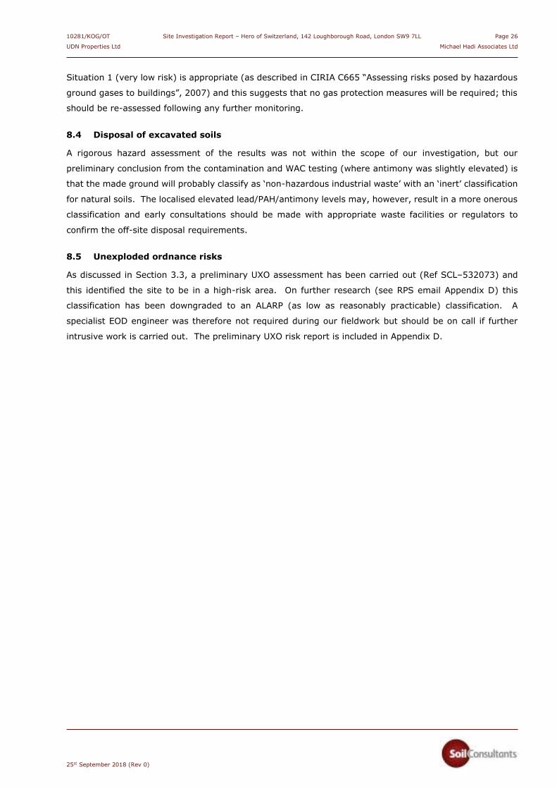
10281/KOG/OT Site Investigation Report – Hero of Switzerland, 142 Loughborough Road, London SW9 7LL Page 26
UDN Properties Ltd Michael Hadi Associates Ltd
25st September 2018 (Rev 0)
Situation 1 (very low risk) is appropriate (as described in CIRIA C665 “Assessing risks posed by hazardous
ground gases to buildings”, 2007) and this suggests that no gas protection measures will be required; this
should be re-assessed following any further monitoring.
8.4 Disposal of excavated soils
A rigorous hazard assessment of the results was not within the scope of our investigation, but our
preliminary conclusion from the contamination and WAC testing (where antimony was slightly elevated) is
that the made ground will probably classify as ‘non-hazardous industrial waste’ with an ‘inert’ classification
for natural soils. The localised elevated lead/PAH/antimony levels may, however, result in a more onerous
classification and early consultations should be made with appropriate waste facilities or regulators to
confirm the off-site disposal requirements.
8.5 Unexploded ordnance risks
As discussed in Section 3.3, a preliminary UXO assessment has been carried out (Ref SCL–532073) and
this identified the site to be in a high-risk area. On further research (see RPS email Appendix D) this
classification has been downgraded to an ALARP (as low as reasonably practicable) classification. A
specialist EOD engineer was therefore not required during our fieldwork but should be on call if further
intrusive work is carried out. The preliminary UXO risk report is included in Appendix D.

10281/KOG/OT Site Investigation Report – Hero of Switzerland, 142 Loughborough Road, London SW9 7LL Page 27
UDN Properties Ltd Michael Hadi Associates Ltd
25st September 2018 (Rev 0)
8.6 Refined Conceptual Site Model
Taking into account the above discussion, the assessed risks to potential receptors identified in the PRA
are summarised in the refined Conceptual Site Model (CSM) below. This includes recommendations for
appropriate mitigation measures to render any SPLs inactive and reduce the risks to receptors to acceptable
levels:
Source
Pathway Receptor Assessed risk, justification and measures to mitigate the risk
to acceptable levels
On site:
contaminated
soil/water
Ingestion &
direct contact
End user Low
Elevated concentrations of lead detected in the made ground.
The near-surface soils were free from visual/olfactory evidence
of volatile compounds/vapours; this was corroborated by
analysis (TPH, PID readings). The SPL to human health will be
inactive.
Made ground will be removed from proposed building footprint
during basement excavation. Beer garden at NE side of site will
remain as hardstanding. The SPL to human health will be
significantly reduced or rendered inactive. If scheme is amended
to include landscaped areas, then all made ground must be
removed, say to 0.60m depth, and replaced with certified clean
imported topsoil with a geofabric separator. The source and
pathway will be removed so the SPL to human health will then
be inactive.
A careful watching brief should be kept during construction and if
obvious or suspected contamination is encountered this should
be dealt with prescriptively.
Ingestion,
contact &
inhalation
Construction
workers and
third parties
Low:
Elevated Lead in made ground identified as SPL to human health.
Any residual risks to these receptors will be managed through
health & safety procedures and CDM regulations
Leaching from
contaminated
soils and
migration in
groundwater
Aquifer and
surface water
Low
100% hard cover expected by the redevelopment which will
prevent any contaminant leaching into the aquifer
100% of made ground will be removed within the building
footprint during basement excavation
Direct contact
with soil/water
Building fabric
and
infrastructure
Low:
The effects of soluble sulphates and alkali/acidic ground are
discussed in Section 6.5 of this report
Detailed assessment of soil/groundwater contamination with
respect to water supply pipes is outside the scope of this report.
See the relevant water authority requirements and UKWIR
‘Guidance for the selection of water supply pipes to be used in
brownfield sites’, 2010.

10281/KOG/OT Site Investigation Report – Hero of Switzerland, 142 Loughborough Road, London SW9 7LL Page 28
UDN Properties Ltd Michael Hadi Associates Ltd
25st September 2018 (Rev 0)
Source
Pathway Receptor Assessed risk, justification and measures to mitigate the risk
to acceptable levels
Off site:
contaminated
soil/water
(see 8.2
above)
Lateral
migration of
contaminants in
groundwater
End-user and
buildings
Low:
No contamination measured in soils which may be associated
with off-site sources.
Further testing including PCB analysis is recommended from site
area closest to recorded substation to south of site
On-site and
off-site:
ground gas &
vapour
Lateral
migration
through strata,
service runs and
cracks in
buildings
End-user and
buildings
Very Low
No significant potential gas sources were identified by the PRA.
Bulk of made ground as potential on-site source will be removed
during basement excavation.
Subsequent monitoring has revealed no elevated levels of
ground gases. The SPL from ground gas is therefore considered
to be inactive.
Radon gas protection measures not required according to
Groundsure report.
In conclusion, based upon the information reviewed and the results of the investigation, our assessment is
that the with appropriate mitigation measures, it should be possible to reduce the risks to acceptable levels.
The required mitigation measures identified above include the replacement of any made ground with
imported topsoil in landscaped areas if these are proposed outside the proposed basement area.
Limited access to the site was available and it is self-evident that there may be zones of contamination
within the site which were not encountered. A careful watching brief should be kept during construction to
ensure that any potentially contaminated soil encountered is disposed of in a safe and controlled manner.
Site workers should observe normal hygiene precautions when handling soils and if material suspected of
being contaminated is identified during construction, this should be set aside under protective cover and
further tests undertaken to verify the nature and levels of contamination present. If contamination is
present, a full site re-assessment may be required and a contingency should be in place in this regard.
9.0 ADDITIONAL INVESTIGATION
Piled foundations or a piled-raft foundation options are the likely options. In this situation additional
investigation to greater depth will be required to provide the appropriate pile design parameters. Further
contamination testing should form part of this additional work to provide additional site coverage for a
more comprehensive assessment.
i i i i i i i i i i i i i i i i i

10281/KOG/OT Site Investigation Report – Hero of Switzerland, 142 Loughborough Road, London SW9 7LL Page 29
UDN Properties Ltd Michael Hadi Associates Ltd
25st September 2018 (Rev 0)
GENERAL INFORMATION, LIMITATIONS AND EXCEPTIONS
Unless otherwise stated, our Report should be construed as being a Ground Investigation Report (GIR) as defined in BS EN1997-2. Our Report is not intended to be and should not be viewed or treated as a Geotechnical Design Report (GDR) as defined in EN1997-2. Any ‘design’ recommendations which are provided are for guidance only and are intended to allow the designer to assess the results and implications of our investigation/testing and to permit preliminary design of relevant elements of the proposed scheme.
The methods of investigation used have been chosen taking into account the constraints of the site including but not limited to access and space limitations. Where it has not been possible to reasonably use an EC7 compliant investigation technique we have adopted a practical technique to obtain indicative soil parameters and any interpretation is based upon our engineering experience and relevant published information.
The Report is issued on the condition that Soil Consultants Ltd will under no circumstances be liable for any loss arising directly or indirectly from ground conditions between the exploratory points which differ from those identified during our investigation. In addition, Soil Consultants Ltd will not be liable for any loss arising directly or indirectly from any opinion given on the possible configuration of strata both between the exploratory points and/or below the maximum depth of the investigation; such opinions, where given, are for guidance only and no liability can be accepted as to their accuracy. The results of any measurements taken may vary spatially or with time and further confirmatory measurements should be made after any significant delay in using this Report.
Comments made relating to ground-water or ground-gas are based upon observations made during our investigation unless otherwise stated. Ground-water and ground-gas conditions may vary with time from those reported due to factors such as seasonal effects, atmospheric effects and and/or tidal conditions. We recommend that if monitoring installations have been included as part of our investigation, continued monitoring should be carried out to maximise the information gained.
Specific geotechnical features/hazards such as (but not limited to) areas of root-related desiccation and dissolution features in chalk/soluble rock can exist in discrete localised areas - there can be no certainty that any or all of such features/hazards have been located, sampled or identified. Where a risk is identified the designer should provide appropriate contingencies to mitigate the risk through additional exploratory work and/or an engineered solution.
Where a specific risk of ground dissolution features has been identified in our Report (anything above a ‘low’ risk rating), reference should be made to the local building control to establish whether there are any specific local requirements for foundation design and appropriate allowances should be incorporated into the design. If such a risk assessment was not within the scope of our investigation and where it is deemed that the ground sequence may give rise to such a risk (for example near-surface chalk strata) it is recommended that an appropriate assessment should be undertaken prior to design of foundations.
Where spread foundations are used, we recommend that all excavations are inspected and approved by suitably experienced personnel; appropriate inspection records should be kept. This should also apply to any structures which are in direct contact with the soil where the soil could have a detrimental effect on performance or integrity of the structure.
Ground contamination often exists in small discrete areas - there can be no certainty that any or all such areas have been located, sampled or identified.
The findings and opinions conveyed in this Report may be based on information from a variety of sources such as previous desk studies, investigations or chemical analyses. Soil Consultants Limited cannot and does not provide any guarantee as to the authenticity, accuracy or reliability of such information from third parties; such information has not been independently verified unless stated in our Report.
Our Report is written in the context of an agreed scope of work between Soil Consultants Ltd and the Client and should not be used in any different context. In light of additional information becoming available, improved practices and changes in legislation, amendment or re-interpretation of the assessment or the Report in part or in whole may be necessary after its original publication.
Unless otherwise stated our investigation does not include an arboricultural survey, asbestos survey, ecological survey or flood risk assessment and these should be deemed to be outside the scope of our investigation.
We will identify tree and plant species if possible, but a suitably qualified arboriculturalist/botanist should be consulted to provide definitive identification

10281/KOG/OT Site Investigation Report – Hero of Switzerland, 142 Loughborough Road, London SW9 7LL
UDN Properties Ltd Michael Hadi Associates Ltd
25st September 2018 (Rev 0)
APPENDIX A
Fieldwork, in-situ testing and monitoring
Foreword Borehole record Standard Penetration Test results SPT hammer calibration certificate Trial pit record Groundwater and gas monitoring results
Laboratory testing
Index property testing Plasticity chart Unconsolidated undrained triaxial test results (QUT) Particle size distribution tests
Ground profiles
Plot of SPT ‘N’ value and undrained cohesion versus depth
Contamination and chemical testing
Foreword General soil suite WAC test results Sulphate/pH suite
Plans, drawings & photographs
Site photographs Proposed development plans and sections Site Plan Location Maps
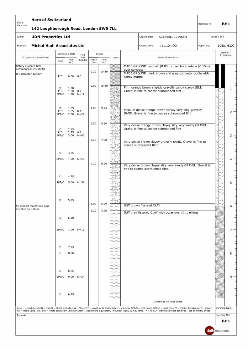
Progress & Observations
Rotary augered hole commenced: 23/08/18
RH diameter 125mm
50 mm ID monitoring pipe installed to 6.00m
Samples & Tests
Type Depth(m)
FieldTest
Results
Strata
Depth(m)
Level(m)
10.80
10.20
9.25
8.60
7.90
6.90
5.20
4.90
Legend Strata Descriptions
MADE GROUND: asphalt (0.05m) over brick rubble (0.15m) over concreteMADE GROUND: dark brown and grey concrete rubble with sandy matrix
Firm orange brown slightly gravelly sandy clayey SILT. Gravel is fine to coarse subrounded flint
Medium dense orange brown clayey very silty gravelly SAND. Gravel is fine to coarse subrounded flint
Very dense orange brown clayey silty very sandy GRAVEL. Gravel is fine to coarse subrounded flint
Very dense brown clayey gravelly SAND. Gravel is fine to coarse subrounded flint
Very dense brown clayey silty very sandy GRAVEL. Gravel is fine to coarse subrounded flint.
Stiff brown fissured CLAY
Stiff grey fissured CLAY with occasional silt partings
Continued on next sheet
Backfill / Installation
1
2
3
4
5
6
7
8
9
PID 0.50 0.3
D 1.00PID 1.00 0.2
SPT/S 1.20 N=11
D 1.85PID 1.85 0.1
SPT/C 2.00 N=22
D 2.75PID 2.75 0.2
SPT/C 3.00 N=63
D 3.75
SPT/C 4.00 N=55
D 4.75
SPT/C 5.00 N=51
D 5.75
U 6.50
SPT/C 7.00 N=13
D 7.75
U 8.00
D 8.75
SPT/C 9.00 N=24
D 9.75
0.30
0.90
1.85
2.50
3.20
4.20
5.90
6.20
Site &Location:
Hero of Switzerland
142 Loughborough Road, London SW9 7LLBorehole No: BH1
Client: UDN Properties Ltd Coordinates: 531695E, 175965N Sheet 1 of 2
Engineer: Michal Hadi Associates Ltd Ground Level: +11.10mOD Report No: 10281/KOG
Key: U = Undisturbed B = Bulk D = Small disturbed W = Water ES = glass jar & plastic tub E = glass jar SPT/S = split spoon SPT/C = solid cone PP = Pocket Penetrometer [kg/cm²]HV = Hand Vane [kPa] PID = Photo Ionisation Detector [ppm - Isobutylene Equivalent, PhoCheck Tiger, 10.6eV lamp] * = full SPT penetration not achieved - see summary sheet
Borehole type:
Remarks: Borehole No:
BH1

Progress & Observations
RH complete: 23/08/18 RH depth: 12.00m Casing installed to 6.00m Water depth: 4.20m
Samples & Tests
Type Depth(m)
FieldTest
Results
Strata
Depth(m)
Level(m)
1.10
-0.90
Legend Strata Descriptions
Stiff grey fissured CLAY with occasional silt partings
End of hole at 12.00m
Backfill / Installation
10
11
12
13
14
15
16
17
18
19
U 10.00
D 10.75
U 11.00
D 11.55SPT/C 11.55 N=29
10.00
12.00
Site &Location:
Hero of Switzerland
142 Loughborough Road, London SW9 7LLBorehole No: BH1
Client: UDN Properties Ltd Coordinates: 531695E, 175965N Sheet 2 of 2
Engineer: Michal Hadi Associates Ltd Ground Level: +11.10mOD Report No: 10281/KOG
Key: U = Undisturbed B = Bulk D = Small disturbed W = Water ES = glass jar & plastic tub E = glass jar SPT/S = split spoon SPT/C = solid cone PP = Pocket Penetrometer [kg/cm²]HV = Hand Vane [kPa] PID = Photo Ionisation Detector [ppm - Isobutylene Equivalent, PhoCheck Tiger, 10.6eV lamp] * = full SPT penetration not achieved - see summary sheet
Borehole type:
Remarks: Borehole No:
BH1

Site & Hero of Switzerland Report
Location 142 Loughborough Road, London SW9 7LL No:
STANDARD PENETRATION TEST SUMMARY
BH Depth Test N value Blow-counts and penetration Casing Water Remarks
ID (m) type (Note b) Seating blows Test blows depth (m) depth (m)
BH1 1.20 S N=11 1 1 2 2 3 4 0.00 Dry
BH1 2.00 C N=22 3 4 4 5 5 8 0.00 Dry
BH1 3.00 C N=63 7 15 18 20 18 7 0.00 Dry
BH1 4.00 C N=55 10 14 14 12 15 14 0.00 Dry
BH1 5.00 C N=51 9 10 10 12 15 14 0.00 4.20
BH1 7.00 C N=13 3 3 3 3 4 3 6.00 Dry
BH1 9.00 C N=24 3 4 5 6 6 7 6.00 Dry
BH1 11.55 C N=29 6 6 7 7 7 8 6.00 Dry
a) Standard Penetration Test : BS EN ISO 22476:2005 Part 3
b) Where full penetration was not achieved, the total test blow-counts are reported
c) Hammer Energy Ratio, Er = 78%
10281/KOG

Site & Location Hero of Switzerland,
142 Loughborough Road, London SW9 7LL
Report No:
10281/KOG
SPT hammer energy test report

SiteLocation Hero of Switzerland
142 Loughborough Road, London SW9 7LL
Trial Pit No:
TP 01[1 of 1]
Client:
Engineer:
UDN Properties Ltd
Michael Hadi Associates Ltd
Report No:
10281/KOG
D = small disturbed sample, B = bulk sample, HV = hand shear vane test [kPa], pp = pocket penetrometer [kg/cm2]
Date: 23rd August 2018 Groundwater details Samples
Equipment: Excavated with hand tools and breaker • Groundwater seepage met, excavation halted
Stability: Stable
Remarks: Basement level +9.0mOD Logged by: OT
PHOTOGRAPHS:

SiteLocation Hero of Switzerland
142 Loughborough Road, London SW9 7LL
Trial Pit No:
TP 02 [1 of 1]
Client:
Engineer:
UDN Properties Ltd
Michael Hadi Associates Ltd
Report No:
10281/KOG
D = small disturbed sample, B = bulk sample, HV = hand shear vane test [kPa], pp = pocket penetrometer [kg/cm2]
Date: 23rd August 2018 Groundwater details Samples
Equipment: Excavated with hand tools • Dry D 0.50
Stability: Stable
Remarks: Ground level +11.0mOD Logged by: OT
SECTION: A – A’
PHOTOGRAPHS:
GL
0.35
Wall of Public House
TOPSOIL
Concrete
1.40
NW SE
MADE GROUND: brown silt/sand with brick rubble, occasional slate, concrete, mortar, glass and occasional flints
0.75
Unable to penetrate base of pit (due to presence of very dense gravel) or probe underneath concrete with Mackintosh probe (possible natural stratum). Foundation base not proven
Black pipe @ 50mm dia. At abut 0.70m
Pipe
0.15

Date: Monitoring equipmentInstrument: GA5000. Serial No. G505055
Barometric pressure: Calibration check details:a) Trend (24hrs): Falling Next calibration date: b) At start (mB): 2022c) At end (mB): 2022 Notes:
1)
Recorded by: TBH2)
Surface ground conditions: Dry
Weather conditions: Cloudy 3)
Ambient air temp (oC): 17
Results
Max Steady Max Steady Min Steady CO H2S10:40 0.2 0.2 1.8 1.0 16.9 18.3 0.0 0.0 2.1
(mb)5.50 0.0704/09/2018 BH1 3.95 0.10
Date Time (24hr)
Borehole ID GW depth Depth to base CH4 (%) CO2 (%) O2 (%) Highest (ppm) Emission rate Relative pressure PID (m) (m) (l/hr)
Site &Location
Results of groundwater/gas monitoring
04 Sep 18
12 Jan 19
Hero of Switzerland, 142 Loughborough Road, London SW9 7LL 10281/OT
Report No:
Barometric pressure trend and ambient air temperature is recorded from metoffice.gov.uk website on the day of the monitoring visit
Calibration check is performed at start of monitoring against ambient air and also periodically with a 5% CH4, 5% CO2 and 6% O2 gas mixture
CH4 = methane; CO2 = carbon dioxide; CO = carbon monoxide; O2 = oxygen; H2S = hydrogen sulphide
See note 2 below

Site & Report
Location No:
SUMMARY OF UNDRAINED SHEAR STRENGTH TEST RESULTS
BH ID Depth (m)
Moisture content (%)
Bulk density (Mg/m3)
Dry density (Mg/m3)
Cell pressure (kPa)
Deviator stress (kPa)
Failure strain (%)
Failure mode
Undrained cohesion (kPa)
Remarks
BH1 6.50 29 1.94 1.50 130 180 10.00 B 90
BH1 8.00 28 1.89 1.48 160 159 9.00 B 80
BH1 10.00 28 1.93 1.51 200 214 6.00 B 107
BH1 11.00 29 1.93 1.50 220 193 3.00 B 97
Testing in accordance with BS EN ISO 17892. UU = unconsolidated, undrained; MUU = multistage, unconsolidated, undrainedDate: 04 September 18
Unless stated otherwise: a) Rate of strain = 2mm/min and b) Standard latex membrame used with thickness = 0.5mm
Failure modes: B = brittle, I = intermediate, P = plastic
Hero of Switzerland10281/KOG
142 Loughborough Road, London SW9 7LL
(Triaxial Sheet 1 of 1)

Site & Report
Location No:
SUMMARY OF CLASSIFICATION TEST RESULTS
BH ID Depth (m)
Type w (%)
wL
(%)wP
(%)Pass 425 (%)
IP
(%)Mod IP
(%)
IL
(%)LOI (%)
BH1 1.00 D 12 19 15 77** 4 3 -0.75
BH1 6.50 U 29 76 20 >95 56 0.17
BH1 8.00 U 28 76 20 >95 56 0.15
BH1 10.00 U 28 78 29 >95 49 -0.03
BH1 11.00 U 29 83 29 >95 54 0.00
Testing in accordance with BS EN ISO 17892 unless specified otherwise Date: 13 Sep 18
Modified Plasticity Index calculated in accordance with NHBC Standards Chapter 4.2 (reported if %passing 425mm <95%)
Percent passing 425mm: by estimation, by hand* or by sieving**
Hero of Switzerland10281/KOG
142 Loughborough Road, London SW9 7LL
Description
Orange brown slightly gravelly sandy clayey silt
Grey CLAY
Grey CLAY
Grey CLAY
Grey CLAY
(Classification Sheet 1 of 1)

Site & Report
Location No:
M - SILT [plots below the A-Line}
C - CLAY [plots above the A-Line]
Classification in accordance with BS5930:2015 "Code of practice for site investigations"
Hero of Switzerland10281/KOG
142 Loughborough Road, London SW9 7LL
Plasticity Chart
0
10
20
30
40
50
60
70
0 10 20 30 40 50 60 70 80 90 100 110 120
Pla
stic
ity
Ind
ex (
%)
Liquid Limit (%)
London Clay Terrace gravel
L - Low I - intermediate H - High V - Very high E - Extremely high
CL
CI
CH
CE
ML
MI
MV
ME
MH
Upper Plasticity range
CV
London Clay Formation Taplow Gravel

Site Report
Location No:
PARTICLE SIZE DISTRIBUTION
Hole ID: BH1 Description:Depth (m): 1.85
Sieving Sedimentation Sample proportions %Size (mm) % passing Size (mm) % passing Cobbles 0
75 100.0 32.0 26.7 Gravel 2363 100.0 23.0 26.4 Sand 3650 100.0 15.0 24.7 Silt 24
37.5 100.0 11.0 23.7 Clay 1728 100.0 7.0 2220 97.5 5.0 21 Grading analysis
14 92.8 4.0 20.1 D60 mm 0.2610 89.6 3.0 19.2 D30 mm 0.0376.3 0.0 2.0 17.5 D10 mm N/A5 0.0 1.0 17
3.35 17.5 0.3 13.9 Uniformity Coefficient2 19.2 Curvature Coefficient
1.18 20.10.6 21.0 Test method and date
0.425 22.0 Testing in accordance with BS EN ISO 17892:0.3 23.7 - Wet sieving method
0.212 24.7 - Hydrometer method0.15 26.40.063 26.7 Reporting date:
Hero of Switzerland10281/KOG
142 Loughborough Road, London SW9 7LL
Orange brown clayey very silty very gravelly SAND
10 Sep 18
SILT
Fine Medium Coarse
SAND
Fine Medium Coarse
GRAVEL
Fine Medium CoarseCLAY COBBLES BOULDERS
0
10
20
30
40
50
60
70
80
90
100
0.001 0.01 0.1 1 10 100 1000
Perc
en
tag
e P
assin
g
%
Particle Size mm

Site Report
Location No:
PARTICLE SIZE DISTRIBUTION
Hole ID: BH1 Description:Depth (m): 3.75
Sieving Sedimentation Sample proportions %Size (mm) % passing Size (mm) % passing Cobbles 0
75 100.0 32.0 25 Gravel 4263 100.0 22.0 24.8 Sand 3050 100.0 15.0 23.4 Silt 14
37.5 100.0 11.0 22.9 Clay 1428 100.0 8.0 21.220 95.5 5.0 20.1 Grading analysis
14 84.7 4.0 18.6 D60 mm 2.8010 75.7 3.0 17.7 D30 mm 0.0896.3 0.0 2.0 15.6 D10 mm N/A5 0.0 1.0 14.4
3.35 15.6 0.3 11.1 Uniformity Coefficient2 17.7 Curvature Coefficient
1.18 18.60.6 20.1 Test method and date
0.425 21.2 Testing in accordance with BS EN ISO 17892:0.3 22.9 - Wet sieving method
0.212 23.4 - Hydrometer method0.15 24.80.063 25.0 Reporting date:
Hero of Switzerland10281/KOG
142 Loughborough Road, London SW9 7LL
Brown clayey silty very sandy GRAVEL
10 Sep 18
SILT
Fine Medium Coarse
SAND
Fine Medium Coarse
GRAVEL
Fine Medium CoarseCLAY COBBLES BOULDERS
0
10
20
30
40
50
60
70
80
90
100
0.001 0.01 0.1 1 10 100 1000
Perc
en
tag
e P
assin
g
%
Particle Size mm

Site Report
Location No:
PARTICLE SIZE DISTRIBUTION
Hole ID: BH1 Description:
Depth (m): 5.75
Sieving Sedimentation Sample proportions %
Size (mm) % passing Size (mm) % passing Cobbles 0
75 100.0 25.0 16 Gravel 60
63 100.0 18.0 15.7 Sand 23
50 100.0 12.0 15 Silt 7
37.5 90.7 9.0 14.3 Clay 11
28 83.5 6.0 13.8
20 78.0 4.0 13.1 Grading analysis
14 62.9 3.0 11.9 D60 mm 12.15
10 56.0 2.0 11.2 D30 mm 0.378
6.3 0.0 1.0 10.5 D10 mm 0.001
5 0.0 0.9 9.55
3.35 0.0 0.2 7.5 Uniformity Coefficient
2 11.2 Curvature Coefficient
1.18 11.9
0.6 13.1 Test method and date
0.425 13.8 Testing in accordance with BS EN ISO 17892:
0.3 14.3 - Wet sieving method
0.212 15.0 - Hydrometer method
0.15 15.7
0.063 16.0 Reporting date:
Hero of Switzerland10281/KOG
142 Loughborough Road, London SW9 7LL
Brown clayey silty very sandy GRAVEL
10 Sep 18
SILT
Fine Medium Coarse
SAND
Fine Medium Coarse
GRAVEL
Fine Medium CoarseCLAY COBBLES BOULDERS
0
10
20
30
40
50
60
70
80
90
100
0.001 0.01 0.1 1 10 100 1000
Perc
en
tag
e P
ass
ing
%
Particle Size mm

Site & Report No:
Location
Hero of Switzerland10281/KOG
142 Loughborough Road, London SW9 7LL
Undrained cohesion and SPT-N vs depth
0 10 20 30 40 50 60 70 80 90 100
0
2
4
6
8
10
12
14
0 50 100 150 200 250 300 350 400 450 500
SPT N
Dep
th (
m)
Undrained cohesion - triaxial (kPa)
Undrained cohesion SPT 'N' value
London Clay Formation
Taplow Gravel
Made ground
Proposed basement formation

Rev: August 2009
Foreword to: CONTAMINATION TESTING AND ASSESSMENT The following statements are designed to inform and guide the Client and other potential parties intending to rely upon this report, with the express intent of protecting them from misunderstanding as to the extent and thus the potential associated risks that may result from proceeding without further evaluations or guidance. 1) Unless otherwise stated in this report, the testing of soils and waters is based on a
range of commonly occurring potential contaminants for the specific purpose of providing a general guidance evaluation for the proposed form of development. Thus, the range of potential contaminants is neither exhaustive nor specifically targeted to any previous known uses or influences upon the site.
2) The amount and scope of the testing should not be assumed to be exhaustive but has
been selected, at this stage, to provide a reasonable, general view of the site ground conditions. In many cases this situation is quite sufficient for the site to be characterised for the purposes of development and related Health and Safety matters for persons involved in or directly affected by the site development works. It must be understood, however, that in certain circumstances aspects or areas of the site may require further investigation and testing in order to fully clarify and characterise contamination issues, both for regulatory compliance and for commercial reasons.
3) The scope of the contamination testing must not automatically be regarded as being
sufficient to fully formulate a remediation scheme. For such a scheme it may be necessary to consider further testing to verify the effectiveness of the remedial work after the site has been treated. It must be understood that a remediation scheme which brings a site into a sufficient state for the proposed development (“fit for purpose”) under current legislation and published guidance, may result in some contamination being left in-situ. It is possible that forthcoming legislation may result in a site being classified by the Local Authority and assigned a “Degree of Risk” related to previous use or known contamination.
4) The scope of the environmental investigation and contamination testing must not be
automatically regarded as sufficient to satisfy the requirements in the wider environmental setting. The risks to adjacent properties and to the water environment are assessed by the regulatory authorities and there may be a requirement to carry out further exploration, testing and, possibly monitoring in the short or long term. It is not possible to sensibly predict the nature and extent of such additional requirements as these are the direct result of submissions to and liaison with the regulatory authorities. It is imperative, therefore, that such submissions and contacts are made as soon as possible, especially if there are perceived to be critical features of the site and proposed scheme, in this context.
5) New testing criteria have been implemented by the Environment Agency to enable a
waste disposal classification to be made. The date of implementation of this Waste Acceptance Criteria (WAC) testing was July 2005. It is this testing that will be used by the waste regulatory authorities, including waste disposal sites, to designate soils for disposal in landfill sites. In certain circumstances, to satisfy the waste regulations, there may be the necessity to carry out additional testing to clarify and confirm the nature of any contamination that may be present. If commercial requirements are significant then this process may also necessitate further field operations to clarify the extent of certain features. Thus, the waste classification must be obtained from the waste regulation authorities or a licensed waste disposal site and we strongly recommend that this classification is obtained as soon as possible and certainly prior to establishing any costings or procedures for this or related aspects of the scheme.

Site &
LocationHero of Switzerland140 Loughborough Road, London SW9 7LL
Report No:
10281/KOG
Site Plan
Tree information interpolated from Tree survey report Ref JSL 3129-770
Dynamic sampler borehole
Key
0 5m
Scale = 1:200@A4
3 storey block of flats
Adjacent multi-storey block of flats
Approximate outline of existing building
Grassed area
Beer Garden
Approximate outline of existing basement
TP2 BH1
Lime tree 17m
Cherry 9m
Trial pit
TP1
Paving
Concrete
Asphalt
Paved pedestrian area
Gardens
Car park/access

Site &
LocationHero of Switzerland140 Loughborough Road, London SW9 7LL
Report No:
10281/KOG
Location Plan
(Contains Ordnance Survey data © Crown copyright and database right 2018)
SITE LOCATION
~
~

10281/KOG/OT Site Investigation Report – Hero of Switzerland, 142 Loughborough Road, London SW9 7LL
UDN Properties Ltd Michael Hadi Associates Ltd
25st September 2018 (Rev 0)
APPENDIX B
GroundSure historical maps (Ref SCL-5320272) GroundSure EnviroInsight Report (Ref SCL-5320270) GroundSure GeoInsight Report (Ref SCL-5320271)

10281/KOG/OT Site Investigation Report – Hero of Switzerland, 142 Loughborough Road, London SW9 7LL
UDN Properties Ltd Michael Hadi Associates Ltd
25st September 2018 (Rev 0)
APPENDIX C
Lambeth Council Contaminated land and historical land use search report

Our Ref: ESH_CONTLAND_167 Your Ref: FAO Opher Tolkovsky Chiltern House, Earl Howe Road, Holmer Green High Wycombe, Bucks HP15 6QT 15th August 2018 Dear Mr Tolkovsky, Re: Contaminated land and historical land use search for Hero of Switzerland, 142 Loughborough Rd, SW9 7LL. Thank you for your request for information regarding records of entry in our Contaminated Land Database in respect of the above location.
We have searched our database for records we have on Hero of Switzerland, 142 Loughborough Rd, SW9 7LL and the surrounding area and there are no records of contamination. Please note that we have no enforcement concerns relating to Part IIA of the Environmental Protection Act 1990 and we do not intend to carry out any investigation under this legislation.
We have also searched information we have containing historical use and activity for the land surrounding the subject location. In light of the information provided I confirm we have no enforcement concerns relating to Part IIA of the Environmental Protection Act 1990 and we do not intend to carry out any investigation under this legislation.
Search Address Address Post Code Date Description Grid X Grid Y Grid Ref: Start
Date End Date
105 Minet Road, Camberwell
sw97uh 0
Listers Geotechnical Consultants, Lovell Ground investigation. 531850 176050A tq318760
LBL Depot 105 Minet Road, London
SW97UH 2001
planning approval granted for the change of use of industrial land currently used as a car breakers yard and artists studio into
531900M 176000M TQ318760

10281/KOG/OT Site Investigation Report – Hero of Switzerland, 142 Loughborough Road, London SW9 7LL
UDN Properties Ltd Michael Hadi Associates Ltd
25st September 2018 (Rev 0)
APPENDIX D
GroundSure Preliminary Unexploded Ordnance Risk Report (Ref SCL–532073) RPS UXO Classification Email Report dated 24 sept 2018

5 Risk of UXO based on WWII German bombing density
Crown Copyright 2018. All rights reserved. Licence Number 1000047514
Dynasafe BACTEC Limited
NEGLIGIBLE
LOW
MEDIUM
HIGH
1:20000
0 800400
Metres
Dynasafe BACTEC Limited and FIND Mapping Limited 09 Report reference: 502963

6 Risk of UXO based on WWII German bomb strikes
Crown Copyright 2018. All rights reserved. Licence Number 1000047514
Dynasafe BACTEC Limited BOMB STRIKESWITH BUFFER
1:5000
0 200100
Metres
Dynasafe BACTEC Limited and FIND Mapping Limited 10 Report reference: 502963

7 Risk of UXO based on 250m gridded bomb damage
Crown Copyright 2018. All rights reserved. Licence Number 1000047514
Dynasafe BACTEC Limited
LOW
MEDIUM
HIGH
V1 STRIKE
V2 STRIKE
1:5000
0 200100
Metres
Dynasafe BACTEC Limited and FIND Mapping Limited 11 Report reference: 502963

8 Conclusions
Risk Levels and Recommendation
Indicative British / Allied UXO Risk
HIGHThere are significant potential sources of British / Allied UXO recorded in Dynasafe BACTEC’s historicaldatabase in proximity to the site. It is recommended that further research is undertaken to determinemore about these sources and to what degree they may have affected the site. Given the proximity andsignificance of these sources, the risk on site from UXO is considered to be High.
Indicative German UXO Risk
HIGHHistorical records indicate an overall high bombing density for the borough in which the site lies, highlevels of damage ascribed to structures in the area (serious damage to total destruction), and a bombstrike(s) recorded within 50m of the site on the London ARP Bomb Census Maps.
Where high bomb damage and bomb strikes are recorded, there is a likelihood that rubble and debris waspresent which could have obscured entry holes of UXBs.
As a result, this preliminary assessment has identified a High risk from German UXBs at this site.
ConclusionThis preliminary assessment has resulted in an overall High risk from UXO. Dynasafe BACTEC wouldrecommend that a Detailed UXO Threat Assessment Desk Top Study is undertaken for this site.
Detailed assessments are conducted offline by Dynasafe BACTEC’s researchers and use informationsuch as historical mapping, WWII-era aerial photography, written air-raid precaution records and wherenecessary local archive research to fully qualify the risk on site. Land use, changes to building layoutduring WWII and post war redevelopment will also have an impact on any remaining level of risk fromUXO. It is often possible to ‘zone’ sites into different risk categories. The lead time for a detailedassessment will vary between 3-10 working days dependent upon the complexity of the site and theadditional site specific information required.
For a quotation, or more information, please contact Dynasafe BACTEC on 01322 284 550.
Dynasafe BACTEC Limited and FIND Mapping Limited 12 Report reference: 502963

1
cardiff
From: Rhys Pearson <[email protected]>
Sent: 24 September 2018 16:21To: cardiffSubject: RE: Hero of Switzerland
Good afternoon, apologies for the delayed response. Upon review of the information provided and a review of construction and intrusive works completed on site (post WWII), RPS considered the risk on site to be ALARP. As such suitable and sufficient UXO mitigation would be an on‐call Explosives Engineer. In the event that a suspect item being encountered by the workforce, RPS would have provided an Engineer to review the item and if necessary provided UXO Support. I hope the above is suitable for your report but if you need further info, please let me know. Kind Regards, Rhys
Rhys Pearson Explosives Safety Consultant RPS Energy, Explosives Engineering Services iversi e ourt eau ort ar e sto onmout s ire .nite in om
T F

10281/KOG/OT Site Investigation Report – Hero of Switzerland, 142 Loughborough Road, London SW9 7LL
UDN Properties Ltd Michael Hadi Associates Ltd
25st September 2018 (Rev 0)
APPENDIX E
Stephen Buss Environmental Consulting Ltd, Hero of Switzerland, 142 Loughborough Road, Basement Impact Assessment. Report ref. 2018-003-050-001, September 2018
Client: UDN Properties Ltd
Dated: September 2018
www.hydro-geology.co.uk
32 Port Hill Road, Shrewsbury SY3 8SA
Registered in England and Wales number 08595273
Stephen Buss Environmental Consulting Ltd
Hero of Switzerland: Basement Impact Assessment, hydrology and hydrogeology
Version control log
Document number Date Issued by Issued to Comments
2018-003-050-001 21 September 2018 Steve Buss Soil Consultants First draft

Hero of Switzerland: Basement Impact Assessment, hydrology and hydrogeology
Page i
DISCLAIMER
This report has been prepared by Stephen Buss Environmental Consulting Ltd (SBEC) in its
professional capacity as hydrogeologist, in a manner consistent with the level of care and skill
ordinarily exercised by members of the geological and engineering professions practising at this
time, within the agreed scope and terms of contract, and taking account of the manpower and
resources devoted to it by agreement with its client.
The advice and opinions in this report should be read and relied on only in the context of the
report as a whole. As with any environmental appraisal or investigation, the conclusions and
observations are based on limited data. The risk of undiscovered environmental impairment of
the property cannot be ruled out. SBEC cannot therefore warrant the actual conditions at the
site and advice given is limited to those conditions for which information is held by SBEC at the
time. The findings are based on the information made available to SBEC at the date of the report
(and will have been assumed to be correct) and on current UK standards, codes, technology and
practices as at that time.
This report is provided to the client addressed above. Should the client wish to release this report
to any other third party for that party’s reliance, SBEC accepts no responsibility to any third party to whom this report or any part thereof is made known. SBEC accepts no responsibility
for any loss or damage incurred as a result, and the third party does not acquire any rights
whatsoever, contractual or otherwise, against SBEC except as expressly agreed with SBEC in
writing.
The findings do not purport to include any manner of legal advice or opinion. New information
or changes in conditions and regulatory requirements may occur in future, which will change the
conclusions presented here.

Hero of Switzerland: Basement Impact Assessment, hydrology and hydrogeology
Page ii
TABLE OF CONTENTS
1. Introduction ........................................................................................................................................ 1
1.1 Background ................................................................................................................................. 1
1.2 Basement Works ......................................................................................................................... 1
1.3 Scope of Report .......................................................................................................................... 3
1.4 Authorship of Report ................................................................................................................ 3
2. Physical Setting, Hydrology and Hydrogeology ............................................................................. 4
2.1 Site History .................................................................................................................................. 4
2.2 Local Basements ......................................................................................................................... 4
2.3 Drainage and Topography ........................................................................................................ 4
2.4 Flooding ....................................................................................................................................... 6
2.5 Local Geology and Hydrogeology ........................................................................................... 7
2.6 Site Geology and Groundwater................................................................................................ 8
3. Site Conceptual Model and Impact Assessment .......................................................................... 10
3.1 Current Groundwater Conditions ......................................................................................... 10
3.2 Risk of Groundwater Flooding .............................................................................................. 10
3.3 Impact Assessment .................................................................................................................. 11
4. Conclusions ....................................................................................................................................... 12
Figures Figure 1.1 Location of Hero of Switzerland ........................................................................................... 1 Figure 1.2 Section of the proposed development .................................................................................. 2 Figure 2.1 The rivers Effra (west) and Peck (east) and Earl’s Sluice (centre) near Brixton ............. 5 Figure 2.2 Risk of surface water flooding................................................................................................ 6 Figure 2.3 Geological section NE of the Hero of Switzerland ............................................................ 8 Figure 2.4 Schematic borehole log ........................................................................................................... 9

Hero of Switzerland: Basement Impact Assessment, hydrology and hydrogeology
Page 1
1. Introduction 1.1 Background This report presents the hydrology and hydrogeology components of a basement impact
assessment, to be submitted in support of a planning application for the development of the
Hero of Switzerland, Brixton, London SW9 7LL (Figure 1.1, national grid reference
TQ 3169 7595). The local planning authority is Lambeth Council.
Figure 1.1 Location of Hero of Switzerland
1.2 Basement Works The site is located between the Loughborough Road and Featley Road, in Brixton. Its
dimensions are approximately 15 m by 35 m. The Hero of Switzerland is a pub that comprises a
part two-storey building, with a cellar beneath part of the building footprint.
The site is surrounded by apartment blocks: a three-storey block with shops on the ground floor
is to the south (150-160 Loughborough Road), and to the north is an eleven-storey block
Hero of Switzerland

Hero of Switzerland: Basement Impact Assessment, hydrology and hydrogeology
Page 2
(Leicester House). The front of the three-storey block is tarmacked while ground around the
eleven-storey apartments is grassed.
The ground around the site is flat. The topographic plan (by Arena Property Services Ltd)
indicate that the ground along the south western edge of the pub is at 11.0 m above Ordnance
Datum (AOD) and along the north eastern side (being the beer garden) is at 10.7 m AOD.
Internal ground floor level is about 0.3 m above the external level and the cellar is about 2.5 m
deep.
The plan for site redevelopment is to demolish the building and construct a new 13-storey
mostly residential building, with the lower two storeys under commercial use, with one basement
level. Figure 1.2 shows a section of the lower floors of the proposed building. Finished floor
level of the basement will be 3.5 m below that of the ground floor, so at a level of approximately
7.2 m AOD.
Figure 1.2 Section of the proposed development
Hero of Switzerland: Basement Impact Assessment, hydrology and hydrogeology
Page 3
1.3 Scope of Report This report presents the hydrology and hydrogeology basement impact assessment development
for the development. It answers the following issues highlighted in Lambeth Council’s Draft
Basements Supplementary Planning Document1, dated October 2017:
9.16 The BIA should include:
• Detailed site specific analysis of hydrological… conditions; • Analysis of how the excavation of the basement may impact on the water table and and groundwater
flow, and whether perched water is present; • Details of how flood risk, including risk from groundwater and surface water flooding has been addressed
in the design, including details of any proposed mitigation measures; • Demonstration of how cumulative effects have been considered; • Identify the location of the development in relation to an aquifer or a water course; • Explain how it will impact on flooding and drainage including measures to reduce the risk of flooding to
the proposed basement and neighbouring properties;
This report relies on factual geological and geotechnical information presented by Soil
Consultants (2018) in report number 10281/KOG/OT.
1.4 Authorship of Report Stephen Buss Environmental Consulting Ltd was instructed in September 2018 to complete this
report.
This report has been prepared by Dr Stephen Buss MA MSc CGeol.
Dr Buss is a UK-based independent hydrogeologist with more than
18 years’ consulting experience in solving groundwater and flooding
issues for regulators, water companies and other private sector
organisations. He has completed in excess of eighty basement impact assessments, including the
surface water aspects. Dr Buss is a Chartered Geologist with the Geological Society of London. Dr Buss’s CV and publications list is available at www.hydro-geology.co.uk.
1 https://moderngov.lambeth.gov.uk/documents/s91400/
Appendix%201%20Draft%20LAMBETH%20BASEMENTS%20SPD%202017.pdf
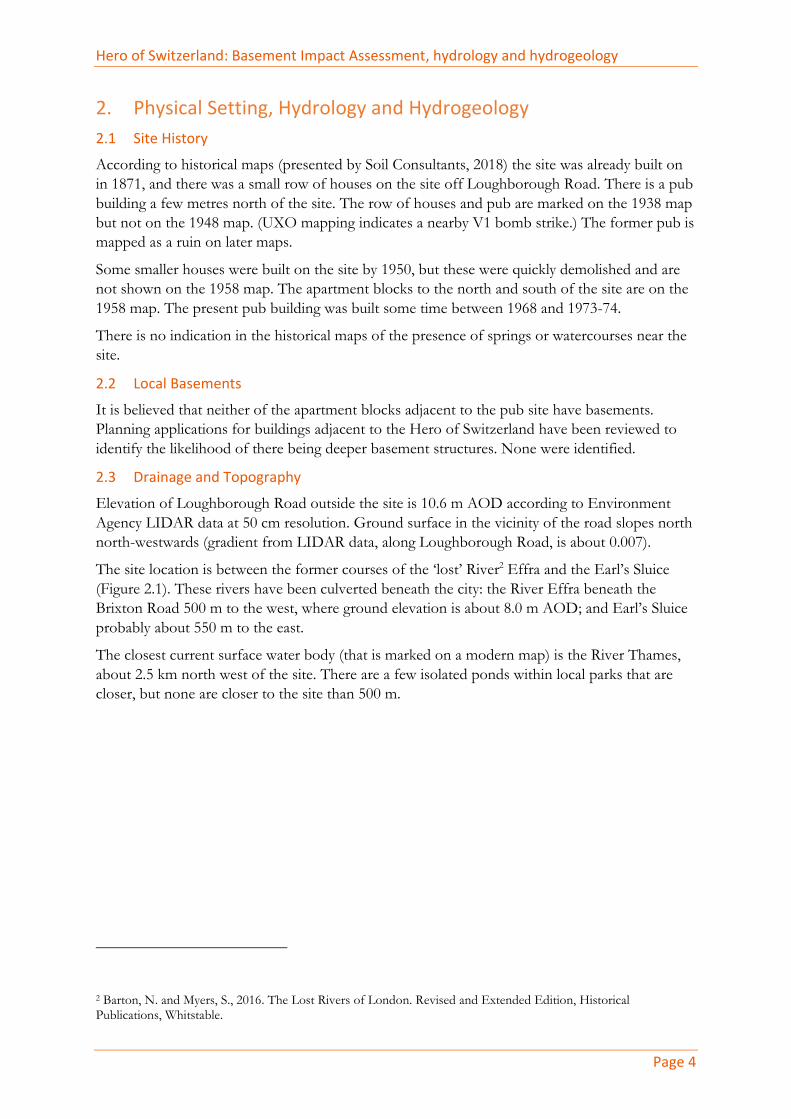
Hero of Switzerland: Basement Impact Assessment, hydrology and hydrogeology
Page 4
2. Physical Setting, Hydrology and Hydrogeology 2.1 Site History According to historical maps (presented by Soil Consultants, 2018) the site was already built on
in 1871, and there was a small row of houses on the site off Loughborough Road. There is a pub
building a few metres north of the site. The row of houses and pub are marked on the 1938 map
but not on the 1948 map. (UXO mapping indicates a nearby V1 bomb strike.) The former pub is
mapped as a ruin on later maps.
Some smaller houses were built on the site by 1950, but these were quickly demolished and are
not shown on the 1958 map. The apartment blocks to the north and south of the site are on the
1958 map. The present pub building was built some time between 1968 and 1973-74.
There is no indication in the historical maps of the presence of springs or watercourses near the
site.
2.2 Local Basements It is believed that neither of the apartment blocks adjacent to the pub site have basements.
Planning applications for buildings adjacent to the Hero of Switzerland have been reviewed to
identify the likelihood of there being deeper basement structures. None were identified.
2.3 Drainage and Topography Elevation of Loughborough Road outside the site is 10.6 m AOD according to Environment
Agency LIDAR data at 50 cm resolution. Ground surface in the vicinity of the road slopes north
north-westwards (gradient from LIDAR data, along Loughborough Road, is about 0.007).
The site location is between the former courses of the ‘lost’ River2 Effra and the Earl’s Sluice
(Figure 2.1). These rivers have been culverted beneath the city: the River Effra beneath the
Brixton Road 500 m to the west, where ground elevation is about 8.0 m AOD; and Earl’s Sluice
probably about 550 m to the east.
The closest current surface water body (that is marked on a modern map) is the River Thames,
about 2.5 km north west of the site. There are a few isolated ponds within local parks that are
closer, but none are closer to the site than 500 m.
2 Barton, N. and Myers, S., 2016. The Lost Rivers of London. Revised and Extended Edition, Historical
Publications, Whitstable.

Hero of Switzerland: Basement Impact Assessment, hydrology and hydrogeology
Page 5
Figure 2.1 The rivers Effra (west) and Peck (east) and Earl’s Sluice (centre) near Brixton
Hero of Switzerland
EARL’S SLUICE

Hero of Switzerland: Basement Impact Assessment, hydrology and hydrogeology
Page 6
2.4 Flooding
2.4.1 Flooding from Rivers and Seas According to the Environment Agency’s map of flood risk for planning purposes, the site is in
flood zone 1, and therefore a flood risk assessment is not necessary on the basis of risk of river
flooding.
2.4.2 Surface Water Flooding The Lambeth Council Surface Water Management Plan
3 (SWMP) indicates that the site is not
within a critical drainage area for surface water flooding. The map of surface water flood risk
from the Environment Agency (Figure 2.2) indicates that there is a part of Featley Road that is at
high risk but this does not extend to within site boundaries. The site itself is at negligible risk of
surface water flooding (with an annual probability of less than 0.001).
Figure 2.2 Risk of surface water flooding
3 https://www.lambeth.gov.uk/sites/default/files/rr-surface-water-management-plan.pdf

Hero of Switzerland: Basement Impact Assessment, hydrology and hydrogeology
Page 7
2.4.3 Sewer Flooding According to the SWMP the site is not in one of the postcode areas with significant history of
sewer flooding, so the risk of sewer flooding can be considered to be negligible.
2.4.4 Groundwater Flooding The site is in an area listed as having ‘increased potential for elevated groundwater in permeable
superficial deposits’ by the SWMP. The likelihood of this hazard being realised is discussed in
Section 3.2. There are, however, no cited records of groundwater flooding on or near
Loughborough Road.
2.5 Local Geology and Hydrogeology Geological mapping indicates that bedrock at the site comprises London Clay which locally
isolates the main drinking water supply aquifer of the London Basin from the surface. The depth
of the chalk aquifer here is about 50 m based on data from a deep borehole at King’s College Hospital
4, 650 m to the east.
Geological mapping shows that superficial deposits comprise sands and gravels of the Taplow
Gravel Member. A line of boreholes5, constructed in 1968 roughly along the line of Minet Road,
150 to 200 m north east of the site, shows a geological section that can be assumed to be
representative of site conditions (Figure 2.3).
The cross-section shows the gravel deposit reaching a thickness of about 4.0 m but thinning
southwards. A near-surface layer of sandy clay / clayey sand overlies the sand and gravel. The
water table is within the sand and gravel unit, about 4.0 m below ground level where present.
4 http://scans.bgs.ac.uk/sobi_scans/boreholes/597849
5 http://scans.bgs.ac.uk/sobi_scans/boreholes/597569

Hero of Switzerland: Basement Impact Assessment, hydrology and hydrogeology
Page 8
Figure 2.3 Geological section NE of the Hero of Switzerland
2.6 Site Geology and Groundwater A ground investigation was completed on site in August 2018. The investigation is reported in
full in Soil Consultants report number 10281/KOG/OT.
One borehole (BH1) was advanced, from the beer garden north east of the building, by rotary
auger, to a depth of 12.0 m. The log shows that below 0.9 m of made ground there was a layer of
sandy clayey silt to 1.85 m depth. A layer of alternating sandy gravel and gravelly sand was found
beneath this and was 4.05 m in thickness. Therefore, London Clay was identified at a depth of
5.2 m. A schematic log is shown in Figure 2.4.
A standpipe was installed in the boreholes to 6.0 m depth, i.e. to the base of the sand and gravel
layer. Groundwater was encountered during drilling, within the sand and gravel, at about 4.2 m
depth. A rest level of 3.95 m was measured during subsequent monitoring.
Clayey sand, becoming
sandy clay to the north
Sand and gravel
London Clay
Water table
BH 504:
dry

Hero of Switzerland: Basement Impact Assessment, hydrology and hydrogeology
Page 9
Figure 2.4 Schematic borehole log
Depth BH10
1
2
3
Basement FFL
Formation level Rest water 3.95 m(assumed) Water strike 4.2 m
5
6
7
11
12
Sandy GRAVEL
LONDON CLAY
MADE GROUND
Sandy clayey
SILT
Gravelly SAND
Sandy GRAVEL
Clayey gravelly
SAND

Hero of Switzerland: Basement Impact Assessment, hydrology and hydrogeology
Page 10
3. Site Conceptual Model and Impact Assessment 3.1 Current Groundwater Conditions Ground beneath the development site comprises a water-bearing layer of sand and gravel, over
low permeability London Clay. When measured in August 2018, groundwater level was observed
in a standpipe at a level close to the expected formation level (Section 2.6).
At the end of a very dry summer, this measurement can be expected to be lower than peak
winter levels. By comparison with typical groundwater level ranges for West London gravels in
CIRIA (1993)6, the peak groundwater level might be expected to be perhaps 0.2 to 0.3 m above
the August 2018 level.
With one borehole, the hydraulic gradient beneath the site cannot be reliably estimated except
that it is probably roughly in the direction of the northward regional slope of the ground.
3.2 Risk of Groundwater Flooding The Lambeth SFRA presents an extract from the groundwater flood susceptibility dataset, by the
British Geological Survey (BGS), as an indication that the site is susceptible to groundwater
flooding at surface. The dataset is a useful tool for highlighting regional areas that are potentially
at risk of groundwater flooding, but at a site scale the dataset is not reliable. The following
section summarises the assumptions behind the dataset7.
The dataset represents two types of groundwater flooding: ‘clearwater’ and ‘PSD’ (permeable superficial deposits). Clearwater flooding is mapped to the outcrop areas of permeable bedrock,
such as the Chalk, much further south of Loughborough Road. The London Clay is not
considered to be permeable bedrock so the modelled groundwater flooding along the
Loughborough Road is PSD flooding.
PSD flooding arises when a river level (or the sea level for coastal sites) rises within its banks, but
there are areas behind the banks that are lower than the crest of the bank. Groundwater may
then flow through the permeable sub-surface to emerge in these hollows that are not connected
to the river by an overland flow path. This is a common phenomenon on the gravels next to the
River Thames, with PSD flooding occurring in south Oxford and in the Maidenhead area.
In creating the PSD flooding dataset the BGS did not use a) a real river dataset, and b) modelled
flood levels (e.g. Environment Agency modelled levels). Instead the survey developed a bespoke
national model of river network and flood elevations at a 50 m resolution. Topography data that
was used to compare ground level with the flood level was also at 50 m resolution (originally OS
Panorama was used, but perhaps now the more modern OS Terrain 50 is used). This resolution
is suitable for regional studies but not site-specific studies.
Loughborough Road runs roughly along the watershed between two former watercourses (the
River Effra and Earl’s Sluice) that both lie more than 500 m from the site (Section 2.3). It is not,
therefore, reasonable to expect that high river levels in either watercourse (which have, of course,
been culverted into the sewer system) will lead to groundwater levels above ground surface at
Loughborough Road.
6 CIRIA, 1993. A Study of the Impact of Urbanisation on the Thames Gravels Aquifer. CIRIA report 129
7 https://www.bgs.ac.uk/research/groundwater/datainfo/GFSD_methodology.html

Hero of Switzerland: Basement Impact Assessment, hydrology and hydrogeology
Page 11
Furthermore, the site is not in a hollow - it is on a gentle slope that falls northwards. So if
flooding was to reach the site it will be river flooding, not groundwater flooding. Environment
Agency flood risk mapping shows that this is not expected (Section 2.4.1).
3.3 Impact Assessment The highest likely groundwater level (including seasonal variation) may be c. 0.3 m, or a little
more, above formation level (Section 3.1). Typically, when a basement constructed with
impermeable material (e.g. the concrete floor slab) is placed into a permeable aquifer with
flowing groundwater, the head of groundwater rises upstream of the basement and drops
downstream of the basement. It appears likely that this will be the case.
The gradient of the water table appears to be approximately northwards but the exact
groundwater flow direction is unknown. Typically, if the system were to be modelled, and if the
basement fully penetrated the sand and gravel aquifer, the rise in groundwater level might be
expected8 to be no more than perhaps 0.4 m on the upstream edge. Since the proposed
basement extends only a very small distance below the water table (relative to the full saturated
thickness) this assumed rise will be a considerable over-estimate.
There are no basements upstream of the proposed basement at the Hero of Switzerland. Hence,
even if there was to be a change in groundwater level there is no basement to be affected. It is
unfeasible to imagine that the groundwater level might rise above ground surface in these
conditions (i.e. starting at around 4.0 m below ground).
The site entirely comprises impermeable surfaces (tarmac, paving and roof), so no water goes to
ground at present. The proposed development does not intend to change this so there will be no
downstream flooding impact from the development.
8 For example, in the ARUP (2010) guidance for subterranean development for Camden Borough Council
(paragraph 172), it is stated that: ‘The change in water levels is in proportion to the increase in the length of the
flow path. In the case of a site measuring 10 m in the direction of groundwater flow, the natural difference in
groundwater level might be one or two centimetres.’

Hero of Switzerland: Basement Impact Assessment, hydrology and hydrogeology
Page 12
4. Conclusions Potential environmental impacts of basement construction at the Hero of Switzerland have been
considered. The following summary conclusions are made:
• There will no overall increase in man-made impermeable area. Therefore, the amount,
timing and quality of surface water runoff will not be reduced by the development. No
water will go to ground as a result of the basement development.
• Available geological and hydrogeological information indicates that there is a permeable
aquifer beneath the site that is water bearing. Groundwater has been detected in one site
borehole roughly at formation level of the proposed basement.
• There are no basements up hydraulic gradient from the basement so there is no risk to
adjacent basements even if groundwater levels were to rise slightly as a result of
basement construction.
• Construction methods and materials will have to take account of the likelihood of
groundwater being present just above formation level.
These conclusions are considered to be robust and no further investigations are needed to satisfy
the screening criteria for groundwater risk or flooding risk.

17132 / Hero of Switzerland – Basement Method Statement 11
Appendix C – Scott White and Hookins’ Flood Risk Assessment and Drainage Strategy, dated April 2019 47 Pages including appendices
Scott White and Hookins LLP Harman House Andover Road Winchester Hampshire SO23 7BS T +44 (0)1962 844855 [email protected]
Prepared by: .............................................. Harry Hunter BEng (Hons) GMICE Reviewed by: .............................................. Richard Hemming BEng MEng CEng MICE
Flood Risk Assessment and Drainage Strategy Hero of Switzerland Loughborough Junction, London

Structural and Civil Engineering Services W02047 Hero of Switerland, Loughborough Junction, London 1 www.swh.co.uk
London Bedford
Winchester
Issue and Amendment Record:
Revision Comment/Amendment Prepared Reviewed Date 01 Preliminary for Comment Harry Hunter Richard Hemming 05/09/18 02 Minor Revisions Harry Hunter Richard Hemming 24/09/18 03 General Updates Harry Hunter Richard Hemming 26/02/19 04 Site Plan Updated Harry Hunter Richard Hemming 04/04/19 05 Drainage Strategy Updated Claire Lang Richard Hemming 05/04/19 06 Site Plan Updated Harry Hunter Richard Hemming 16/04/19
Structural and Civil Engineering Services W02047 Hero of Switerland, Loughborough Junction, London 2 www.swh.co.uk
London
Bedford
Winchester
Contents
1.0 Introduction 3 2.0 Government Policy on Flood Risk and Drainage of Development 4 3.0 Existing Site 11 4.0 Potential Flood Risks 12 5.0 Flood risk mitigation and SUDS proposals 13 6.0 Surface Water Drainage Maintenance Schedule 15 7.0 Summary and Conclusions 18 8.0 Appendices 19

Structural and Civil Engineering Services W02047 Hero of Switerland, Loughborough Junction, London 3 www.swh.co.uk
London
Bedford
Winchester
Introduction
1.1 Scott White and Hookins LLP have been instructed by Macniven Quays Ltd to undertake a
flood risk assessment of a proposed development at The Hero of Switzerland,
Loughborough Junction, London. This flood risk assessment has been produced as a
supporting document for a planning application and takes the form of a desk study.
1.2 The proposed development comprises the demolition of the existing public house, and
erection of a 13-storey building (plus basement and mezzanine floor levels and roof level
access) including a replacement public house with residential units above. The existing site
currently comprises a public house with associated external hardstanding. The development
is classed as More Vulnerable Development under the National Planning Policy Framework
(NPPF) Table 2: Flood Risk Vulnerability Classification. As such it is deemed to be an
Appropriate development for Flood Zone 1 under the NPPF Table 3: Flood Risk Vulnerability
and Flood Zone ‘Compatibility’.
1.3 A location plan is provided in Appendix A. This report considers the flood risk to the
proposed development and the impact that the development will have in relation to
flooding of adjacent areas and watercourses. It also considers any limits relating to flooding
that are likely to be imposed to allow the development to be undertaken and recommends
Sustainable Urban Drainage systems (SUDS) to control surface water runoff.
1.4 This report takes into account the requirements of NPPF, the London Development Plan,
Lambeth Borough Local Plan and is based on information received from the Environment
Agency (EA) web site.
1.5 This report is for the private and confidential use of the client and its agents and may not
be copied in whole or in part without the written permission of Scott White and Hookins
LLP.

Structural and Civil Engineering Services W02047 Hero of Switerland, Loughborough Junction, London 4 www.swh.co.uk
London
Bedford
Winchester
Government Policy on Flood Risk and Drainage of Development
2.1 The frequency and severity of river flooding is perceived to have increased in recent years
and in an attempt to mitigate the flood risk the Government published Planning Policy
Statement Note 25: Development and Flood Risk (PPS25) in December 2006. PPS25 details
the importance of the effective management and reduction of flood risk in the land use
planning process and attempts to address the issue of climate change. This has since been
updated and is set out in The National Planning Policy Framework and the supporting
technical guidance.
2.2 Traditionally surface water run-off from developments has been conveyed by pipe systems
to the nearest watercourse or sewer. This tends to increase the rate and volume of the run
off often leading to flooding downstream of the new development. Latest policy promotes
the use of sustainable urban drainage systems (SuDS) whereby the control of run off is to
be as close to source as possible. This can be achieved by utilising techniques which mimic
the natural drainage processes, the use of direct infiltration for example. The Environment
Agency will, in general, seek to restrict the allowable discharge from a new development to
that previously expected form the undeveloped land.
2.3 The requirements of the revised Building Regulations which came into force on 1st April
2002 are that adequate provision should be made for dealing with rainwater form the roofs
of buildings and certain paved areas providing access to the buildings. Run off from such
drainage systems are to be discharged to one of the following systems listed in order of
priority: -
▪ A soakaway or other infiltration system
▪ A watercourse
▪ A sewer or drain
2.4 The revised Building Regulations were drafted to reinforce the requirements for SuDS
wherever possible.
2.5 The Requirements of a Flood Risk Assessment:
A Flood Risk Assessment is required in order to ascertain whether a development will
exacerbate the risk of flooding elsewhere in the catchment or is at risk of flooding itself.
A site specific FRA is required for: -
▪ Proposals of 1 Hectare or greater situated in Flood Zone 1.
▪ New development (including minor development and change of use) located in
areas of Flood Zone 1 that have critical drainage problems
▪ New development (including minor development and change of use) located in
areas of Flood Zones 2 & 3.

Structural and Civil Engineering Services W02047 Hero of Switerland, Loughborough Junction, London 5 www.swh.co.uk
London
Bedford
Winchester
2.6 The Department for Environment, Food and Rural Affairs (DEFRA) Non-Statutory Technical
Standards for Sustainable Drainage Practice Guidance also provides guidance for the
sustainable design of drainage.
2.7 Flood Risk Outside the Development
S1 - Where the drainage system discharges to a surface water body that can
accommodate uncontrolled surface water discharges without any impact on flood risk
form that surface water body (e.g. the sea or a large estuary) the peak flow control
standards below (S2 and S3) and volume control technical standards (S4 and S5) need not
apply.
2.8 Peak Flow Control
S2 - For greenfield developments, the peak runoff rate from the development to any
highway drain, sewer or surface water body for the 1 in 1 year rainfall event and the 1 in
100 year rainfall event should never exceed the peak greenfield runoff rate for the same
event.
S3 - For developments which were previously developed, the peak runoff rate from the
development to any drain, sewer or surface water body for the 1 in 1 year rainfall event
and the 1 in 100 year rainfall event must be as close as reasonably practicable to the
greenfield runoff rate from the development for the same rainfall event, but should never
exceed the rate of discharge from the development prior to redevelopment for that event.
2.9 Volume Control
S4 - Where reasonably practicable, for greenfield development, the runoff volume from
the development to any highway drain, sewer or surface water body in the 1 in 100 year, 6
hour rainfall event should never exceed the greenfield runoff volume for the same event.
S5 - Where reasonably practicable, for developments which have been previously
developed, the runoff volume from the development to any highway drain, sewer or
surface water body in the 1 in 100 year, 6 hour rainfall event must be constrained to a
value as close as is reasonably practicable to the greenfield runoff volume for the same
event, but should never exceed the runoff volume from the development site prior to
redevelopment for that event.
S6 - Where it is not reasonably practicable to constrain the volume of runoff to any drain,
sewer or surface water body in accordance with S4 or S5 above, the runoff volume must
be discharged at a rate that does not adversely affect flood risk
2.10 Flood Risk Within the Development
S7 - The drainage system must be designed so that, unless an area is designated to hold
and/or convey water as part of the design, flooding does not occur on any part of the site
for a 1 in 30 year rainfall event.

Structural and Civil Engineering Services W02047 Hero of Switerland, Loughborough Junction, London 6 www.swh.co.uk
London
Bedford
Winchester
S8 - The drainage system must be designed so that, unless an area is designated to hold
and/or convey water as part of the design, flooding does not occur during a 1 in 100 year
rainfall event in any part of: a building (including a basement); or in any utility plant
susceptible to water (e.g. pumping station or electricity substation) within the
development.
S9 - The design of the site must ensure that, so far as is reasonably practicable, flows
resulting from rainfall in excess of a 1 in 100 year rainfall event are managed in
exceedance routes that minimise the risks to people and property.
2.11 Structural Integrity
S10 - Components must be designed to ensure structural integrity of the drainage system
and any adjacent structures or infrastructure under anticipated loading conditions over the
design life of the development taking into account the requirement for reasonable levels
of maintenance.
S11 - The materials, including products, components, fittings or naturally occurring
materials, which are specified by the designer must be of a suitable nature and quality for
their intended use.
2.12 Designing for Maintenance Considerations
S12 - Pumping should only be used to facilitate drainage for those parts of the site where
it is not reasonably practicable to drain water by gravity.
2.13 Construction
S13 - The mode of construction of any communication with an existing sewer or drainage
system must be such that the making of the communication would not be prejudicial to
the structural integrity and functionality of the sewerage or drainage system.
S14 - Damage to the drainage system resulting from associated construction activities
must be minimised and must be rectified before the drainage system is considered to be
completed.
2.14 London Local Plan Policy 5.12
Policy 5.12 of the London Local Plan seeks to address current and future flood issues and
minimise risks in a sustainable and cost-effective way.
Development proposals must comply with the flood risk assessment and management
requirement set out in the NPPF and the associated technical guidance on flood risk over the

Structural and Civil Engineering Services W02047 Hero of Switerland, Loughborough Junction, London 7 www.swh.co.uk
London
Bedford
Winchester
lifetime of the development and have regard to measures proposes in Thames Estuary 2100
(TE2100) and catchment Flood Management Plans
Developments which are required to pass the Exception Test set out in the NPPF and the
Technical Guidance will need to address flood resilient design and emergency planning by
demonstrating that:
x The development will remain safe and operational under flood conditions
x A strategy of either safe evacuation and/or safely remaining in the building is
followed under flood conditions
x Key services including electricity, water etc will continue to be provided under
flood conditions
x Buildings are designed for quick recovery following a flood
Development adjacent to flood defences will be required to protect the integrity of
existing flood defences and wherever possible should aim to be set back from the banks
of the watercourses and those defences to allow their management, maintenance and
upgrading to be undertaken in a sustainable and cost effective way.
In line with the NPPF and the Technical Guidance, boroughs should, when preparing LDFs,
utilise Strategic Flood Risk Assessments to identify areas where particular flood risk issues
exist and develop actions and policy approaches aimed at reducing these risks, particularly
through redevelopment of sites at risk of flooding and identifying specific opportunities
for flood risk management measures.
2.15 London Local Plan Policy 5.13
Development should utilise sustainable urban drainage systems (SUDS) unless there are
practical reasons for not doing so, and should aim to achieve greenfield run-off rates and

Structural and Civil Engineering Services W02047 Hero of Switerland, Loughborough Junction, London 8 www.swh.co.uk
London
Bedford
Winchester
ensure that surface water run-off is managed as close to its source as possible in line with the
following hierarchy:
x Store rainwater for later use
x Use infiltration techniques, such as porous surfaces in non-clay areas
x Attenuate rainwater in ponds or open water features for gradual release
x Attenuate rainwater by storing in tanks or released water features for gradual
release
x Discharge rainwater direct to a watercourse
x Discharge rainwater to a surface water sewer/drain
x Discharge rainwater to the combined sewer.
Drainage should be designed and implemented in ways that deliver other policy objectives of
this Plan, including water use efficiency and quality, biodiversity, amenity and recreation.
Within LDFs boroughs should, in line with the Flood and Water Management Act 2010,
utilities Surface Water Management Plans to identify areas where there are particular surface
water management issues and develop actions and policy approaches aimed at reducing
these risks.
2.16 Lambeth Borough Council Local Plan
EN 5 Flood Risk
The council will seek minimise the impact of flooding in the borough through:
x Applying a sequential, risk based approach to the location of the development to avoid
where possible, flood risk to people and property and manage any residual risk, taking
account of the impacts of climate change over the lifetime of the development;
- Steering development towards areas of lowest flood risk, both across Lambeth and
within the development site boundary, through the application of the Sequential Test in
accordance with the NPPF, taking the vulnerability of the proposed uses into account, as
set out in the Lambeth Strategic Flood Risk Assessment (SFRA);
- Ensuring development does not increase flood risk and where possible reduces flood
risk for all forms of flooding;
- Permitting appropriate development in Flood Zones 1, 2, 3a and 3b subject to meeting
the criteria set out in Annex 5; and
- Taking account of the flood risk management measures identified by the Thames
Estuary 2100 Plan.

Structural and Civil Engineering Services W02047 Hero of Switerland, Loughborough Junction, London 9 www.swh.co.uk
London
Bedford
Winchester
x All development in Flood Zones 2, 3a and 2b defined in the SFRA, or identified as at risk
of flooding from other sources, should contribute positively to actively reducing flood
risk though avoidance, reduction, management and mitigation.
x A Flood Risk Assessment will be required for major development proposals within Flood
Zone 1, all development within Flood Zones 2, 3a and 3b, or where the development
may be subject to other sources of flooding. The FRA should be proportionate with the
degree of flood risk posed to and by the proposed development; consider the impact of
climate change on flood risk to and from the development using the latest government
guidance; and take account of the advice and recommendations set out in the SFRA and
Local Flood Risk Management Strategy (LFRMS).
x FRAs must consider the risk of both on and off-site flooding to and from the
development for all sources of flooding including fluvial, tidal, surface run-off,
groundwater, ordinary watercourse, sewer and reservoir.
x For all developments, it must be demonstrated that the development will be safe, and
where required, it will reduce fluvial, tidal, surface run off and groundwater flood risk
and manage residual risks through appropriate flood risk measures, including the use of
sustainable drainage systems (SuDS) in accordance with Policy EN6. Measures to
mitigate flooding from sewers should be discussed with Thames Water Utilities Ltd. And
be included in development proposals for which this is a risk.
x Basement proposals (excluding self contained dwellings in FZ3) shall incorporate
appropriate mitigation measures to ensure the development is safe from all forms of
flooding and does not increase flood risk elsewhere.
x For developments adjacent to the River Thames, and River Graveney, maintenance,
remediation and improvements to the flood defence walls will be required where
necessary. Developments adjacent to defences and culverts should demonstrate that
their development will not undermine the structural integrity of detrimentally impact
upon its intended operation.
EN 6 Sustainable Drainage Systems and Water Management
Development proposals should:
x Maximise opportunities for restoring river channels, flood flow pathways and
floodplains to their natural state and managing surface run-off above ground and as
close o the source as possible to reduce flood risks downstream; and implement
sustainable water management through water sensitive urban design (WSUD).
x Provide compensatory storage to ensure that there is no loss in flood storage capacity
where flood storage is removed, as set out in the Strategic Food Risk Assessment
(SFRA);
x Ensure that the layout and design does not have detrimental impact on floodwater flow
routes across the site;
x Demonstrate that there will be a net decrease in both the volume and rate of run-off
leaving the site by incorporating sustainable drainage systems (SUDS) in line with the
London Plan drainage hierarchy and National SuDS Standards to maximise amenity and
biodiversity benefits and improve the quality of water discharges, Details submitted to
the council to demonstrate compliance with this policy should follow the design
principles within the National SuDS Standards and the current SuDS manual and

Structural and Civil Engineering Services W02047 Hero of Switerland, Loughborough Junction, London 10 www.swh.co.uk
London
Bedford
Winchester
guidance identified within the councils SFRA or Local Flood risk Management Strategy
(LFRMS).
x Seek to improve the water environment in line with the requirements of the European
Water Framework Directive 2000 and its associated legislation, and the Thames River
Basin Management Plan;
x Minimising water consumption and the pressure on the combined sewer network,
through incorporating water efficiency measures including rainwater harvesting, grey
water recycling and other innovative technologies where practical; and
x Demonstrate that the local water supply and public sewerage networks have adequate
capacity both on and off site to serve the development; where there is a capacity
problem and improvements in off site infrastructure are not programmed, the
developer will need to demonstrate that the necessary improvements will be completed
prior to occupation of the development.

Structural and Civil Engineering Services W02047 Hero of Switerland, Loughborough Junction, London 11 www.swh.co.uk
London
Bedford
Winchester
Existing Site
3.1 The site is located on land off Loughborough Road, Loughborough Junction, London. The
site is centred on grid reference TQ 31690 75951 and is approximately 0.04 hectares in size.
A location plan is given in Appendix A.
A copy of the Existing Site Layout is present in Appendix C.
3.2 The site is a Brownfield site comprising a public house and associated hard landscaping. The
developed area of the site is largely flat. Currently the site slopes from the high point of
11.62mAOD to 10.71mAOD.
3.3 A collection of high-rise residential tower blocks with associated hard and soft landscaping
are located to the north of the site. Loughborough Road is located to the east of the site,
with medium rise residential flats beyond. To the south of the site is Hero Square with
associated retail units and hard landscaping in the form of a highway layby and pedestrian
paving. Further high-rise residential tower blocks lie beyond. Medium rise residential flats
with associated hard and soft landscaping are to the west of the site. The site is accessed
from Featley Road on the western boundary of the site.
3.4 The nearest significant watercourse to the site is the River Thames approximately 2.6km
away to the north west.
3.5 Thames Water records indicate there is a public combined sewer to the east of the site
within Loughborough Road. There is another combined sewer to the south of the site within
Featley Road. Sewer record mapping can be found in Appendix B.
3.6 Currently the site is understood to drain to the public combined sewer via a gravity drainage
network.
3.7 British Geological Survey (BGS) maps indicate the site to be underlain by the London Clay
Formation with Sand and Gravel superficial deposits. On this basis it is not likely that
drainage by infiltration techniques would be possible.
3.8 The Environment Agency online groundwater mapping uses the same BGS mapping base
information and classifies the site as an Unproductive Aquifer, which is described as “These are geological strata with low permeability that have negligible significance for water supply or river base flow.”.
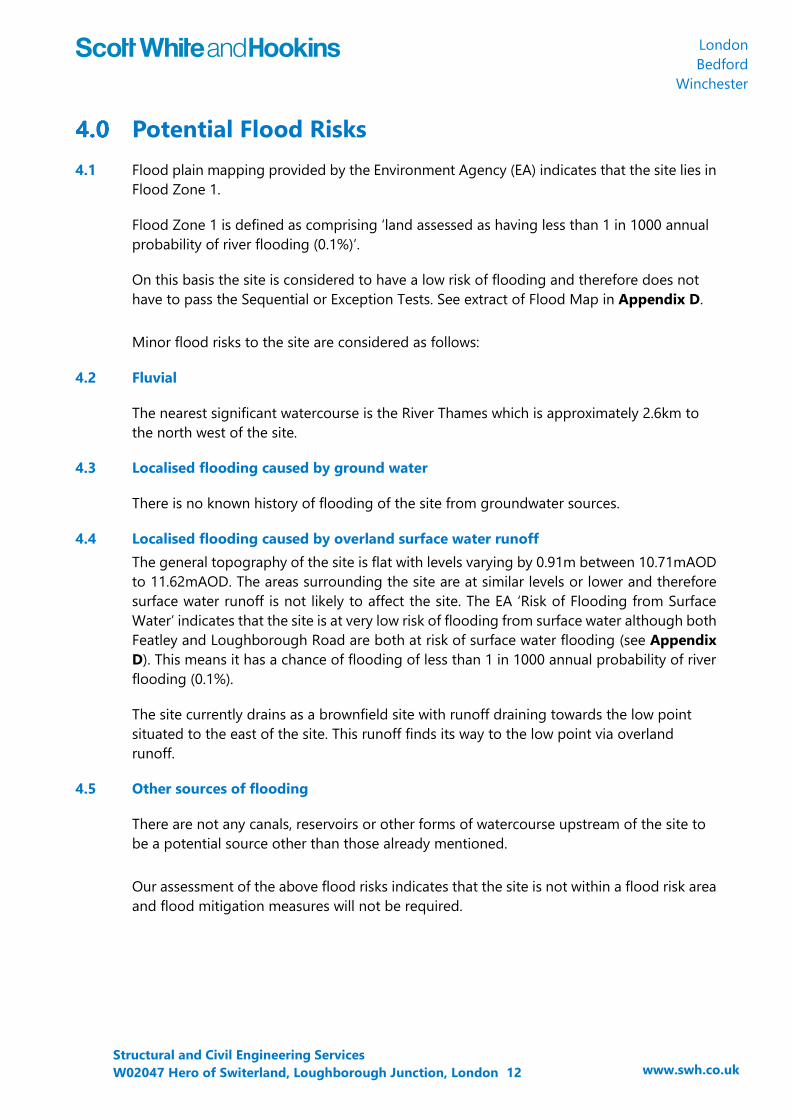
Structural and Civil Engineering Services W02047 Hero of Switerland, Loughborough Junction, London 12 www.swh.co.uk
London
Bedford
Winchester
Potential Flood Risks
4.1 Flood plain mapping provided by the Environment Agency (EA) indicates that the site lies in
Flood Zone 1.
Flood Zone 1 is defined as comprising ‘land assessed as having less than 1 in 1000 annual probability of river flooding (0.1%)’.
On this basis the site is considered to have a low risk of flooding and therefore does not
have to pass the Sequential or Exception Tests. See extract of Flood Map in Appendix D.
Minor flood risks to the site are considered as follows:
4.2 Fluvial
The nearest significant watercourse is the River Thames which is approximately 2.6km to
the north west of the site.
4.3 Localised flooding caused by ground water
There is no known history of flooding of the site from groundwater sources.
4.4 Localised flooding caused by overland surface water runoff
The general topography of the site is flat with levels varying by 0.91m between 10.71mAOD
to 11.62mAOD. The areas surrounding the site are at similar levels or lower and therefore
surface water runoff is not likely to affect the site. The EA ‘Risk of Flooding from Surface Water’ indicates that the site is at very low risk of flooding from surface water although both
Featley and Loughborough Road are both at risk of surface water flooding (see Appendix D). This means it has a chance of flooding of less than 1 in 1000 annual probability of river
flooding (0.1%).
The site currently drains as a brownfield site with runoff draining towards the low point
situated to the east of the site. This runoff finds its way to the low point via overland
runoff.
4.5 Other sources of flooding
There are not any canals, reservoirs or other forms of watercourse upstream of the site to
be a potential source other than those already mentioned.
Our assessment of the above flood risks indicates that the site is not within a flood risk area
and flood mitigation measures will not be required.

Structural and Civil Engineering Services W02047 Hero of Switerland, Loughborough Junction, London 13 www.swh.co.uk
London
Bedford
Winchester
Flood risk mitigation and SUDS proposals
5.1 The development is indicated as being in Flood Zone 1 on the Environment Agency Flood
map and therefore has a low risk of flooding.
5.2 The proposed development comprises the demolition of the existing public house, and
erection of a 13-storey building (plus basement and mezzanine floor levels and roof level
access) including a replacement public house with residential units above. The proposed
site layout can be found in Appendix E.
The site has a total area of 0.045ha and its development would mimic the construction
impermeable areas and result in an increase of surface water run-off.
The existing predevelopment flows are as follows: -
▪ Existing 1 in 1 year flow = 6.2 l/s
▪ Existing 1 in 30 year flow = 16.9 l/s
▪ Existing 1 in 100 year flows = 22.0 l/s
Existing run-off rates can be found in Appendix F.
In order to limit run off from the site and mitigate flood risks to areas downstream, offsite
flow rates should be limited to greenfield rates and SuDS should be used. If a ground
investigation confirms that infiltration techniques alone are feasible then these should be
adopted.
The existing average foul water discharge rates have been calculated at 0.36l/s based on
discharge units in accordance with BS EN 12056-2:2000.
It is proposed to connect the foul water network to the existing combined water manhole
on site. The foul water flows for the proposed development are approximately at 1.67l/s in
accordance with Sewers for Adoption 6th edition.
The basement is to be tanked completely to prevent any ground water ingress. Foul water
discharge from the basement is to be pumped to the proposed gravity foul water network
on the ground floor.
On the basis of the above, the following is proposed: -
▪ Surface water runoff from roof and hardstanding areas to discharge the existing
combined sewer manhole via a cellular storage attenuation tank before discharging
to the public combined sewer.
▪ Foul water network is to discharge to the existing public combined water sewer
located within Loughborough Road via the existing combined sewer manhole.

Structural and Civil Engineering Services W02047 Hero of Switerland, Loughborough Junction, London 14 www.swh.co.uk
London
Bedford
Winchester
Surface Water treatment is to be provided by the various SuDS devices proposed.
Filtration Absorption Biodegradation Sedimentation Volatilisation
Piped
Network
▫
Silt Removal
Devices
▪
At a detailed design stage, other SuDS drainage features such as filter strips, rainwater
harvesting, rainwater butts, and bio retention areas could be considered.
A Proposed Drainage Strategy showing the above outline proposals is presented in
Appendix G.
5.3 To ensure drainage elements are maintained, maintenance of drainage should be covered
by a suitable management company and subject to a regular maintenance regime.
Maintenance of SuDS to be in accordance with CIRIA SuDS manual C753 where specific
intervals are advised within the document as per element type.

Structural and Civil Engineering Services W02047 Hero of Switerland, Loughborough Junction, London 15 www.swh.co.uk
London
Bedford
Winchester
Surface Water Drainage Maintenance Schedule
6.1 This section sets out the inspection and maintenance requirements for long term
management of the developments surface water drainage strategy. This work is to be
undertaken by private maintenance company.
6.2 All those responsible for maintenance should take appropriate health, safety and welfare
precautions for all activities including lone working, if relevant, and risk assessments should
always be undertaken. The sites infrastructure Health and Safety File should be consulted
before carrying out any works either inside or outside of the developments boundary and
information regarding the location of existing utilities passed on to operatives.
6.3 The requirements of the Health and Safety at Work Act 1974 and The Construction (Design
and Management) Regulations 2015 should be adhered to and any residual risks identified
in the Health and Safety File should be managed and information passed on the
maintenance operatives through task specific risk assessments.
There are three types of maintenance activities associated with surface water drainage
systems.
The SuDS Manual, CIRIA C753, defines these as:
▪ Regular Maintenance – ‘basic tasks undertaken on a frequent and predictable schedule’ including vegetation management, litter and debris removal, and inspections.’
▪ Occasional Maintenance – ‘tasks that are likely to be required periodically, but on a much less frequent and predictable basis than the routine tasks (sediment removal
is an example).’ ▪ Remedial Maintenance – ‘intermittent tasks that may be required to rectify faults
associated with the system, although the likelihood of faults can be minimised by
google design. Where remedial work is found to be necessary, it is likely to be due
to site-specific characteristics or unforeseen events, and as such timings are difficult
to predict.

Structural and Civil Engineering Services W02047 Hero of Switerland, Loughborough Junction, London 16 www.swh.co.uk
London
Bedford
Winchester
6.4 SuDS Components Operation and Maintenance Activities
Operation and Maintenance Activity
SuDS Component Piped Network / Inspection Chambers
Cellular / Modular Storage
Regular Maintenance Inspection ▪ ▪ Litter and Debris Removal ▪ ▫ Grass Cutting ▫ Occasional Maintenance Sediment Management ▪ ▪ Remedial Maintenance Structure Rehabilitation/
Repair ▫ ▫ ▪ Will be required ▫ May be required Extract from The SuDS Manual Table 32.1 : Typical key SuDS components
operation and maintenance activities
6.5 Piped Network / Chambers
Piped Network/Chambers Maintenance Schedule
Required Action Typical Frequency
Regular Maintenance
Inspect and identify any features that are
not operating correctly. If required take
remedial action
Monthly for three
months, then six
monthly Debris removal from catchment surface /
gratings (where may cause risks to
performance)
Monthly (and after
large storms)
Remove sediment from trapped sumps,
manholes and catchpits. Annually or as
required Remedial Maintenance Repair / rehabilitation of gratings, inlets
and outlets As required
Monitoring Inspect / check all gratings, trapped
sumps, manholes and catchpits to ensure
that they are in good condition and
operating as designed
Annually and after
large storm events
Structure Rehabilitation /
Repair
Regular Maintenance and Monitoring to
identify if repair and / or replacement of
features or pipework is required.
As required

Structural and Civil Engineering Services W02047 Hero of Switerland, Loughborough Junction, London 17 www.swh.co.uk
London
Bedford
Winchester
6.6 Cellular/modular Storage
Cellular Storage Maintenance Schedule
Required Action Typical Frequency
Regular
Maintenance
Inspect and identify any features that are
not operating correctly. If required take
remedial action
Monthly for three
months, then
annually. Remove debris from catchment surface
(where may cause risks to performance)
Monthly
Remove debris from catchment surface
(where may cause risks to performance)
Annually or as
required Remedial
Maintenance
Repair / rehabilitate inlets, outlets,
overflows and vents As required
Monitoring
Inspect / check all inlets, outlets, vents
and overflows to ensure that they are in
good condition and operating as
designed
Annually and after
large storm events
Survey inside of tank for sediment build-
up and remove if necessary
Every 5 years or as
required
Structure Rehabilitation /
Repair
Regular Maintenance and Monitoring to
identify if repair and / or replacement of
storage units is required.
As required
The SuDS Manual Table 21.3: Operation and maintenance requirements for attenuation storage
tanks

Structural and Civil Engineering Services W02047 Hero of Switerland, Loughborough Junction, London 18 www.swh.co.uk
London
Bedford
Winchester
Summary and Conclusions
7.1 The development lies within Flood Risk Zones 1 as indicated on the Environment Agency
flood map. On this basis the site is considered to be at a low risk of flooding.
7.2 The flood mitigation considerations in section 4.0 of this report indicate that no increase in
flood risk, either on site or downstream, has been introduced as a result of the development
and no flood risk reduction measures are required.
7.3 Surface water runoff from the proposed roof and hard standing areas will discharge to the
existing combined sewer via cellular storage crates and an existing combined sewer
manhole.
7.4 Foul water drainage is to discharge to the existing public foul water sewer located within
Loughborough Road via an existing combined sewer manhole.

Structural and Civil Engineering Services W02047 Hero of Switerland, Loughborough Junction, London 19 www.swh.co.uk
London
Bedford
Winchester
Appendices
Appendix A. Site Location Plan Appendix B. Thames Water Sewer Record Mapping Appendix C. Existing Site Layout Appendix D. Environment Agency Flood Mapping Appendix E. Proposed Site Layout Appendix F. MicroDrainage Existing Site Discharge Rates Appendix G. Proposed Drainage Strategy Appendix H. MicroDrainage Storage Calculations

Structural and Civil Engineering Services W02047 Hero of Switerland, Loughborough Junction, London 20 www.swh.co.uk
London
Bedford
Winchester
Appendix A Site Location Plan
(C) Openstreetmap
Site

Structural and Civil Engineering Services W02047 Hero of Switerland, Loughborough Junction, London 21 www.swh.co.uk
London
Bedford
Winchester
Appendix B Thames Water Sewer Record Mapping

Thames Water Utilities Ltd, Property Searches, PO Box 3189, Slough SL1 4W, DX 151280 Slough 13 T 0845 070 9148 E [email protected] I www.thameswater-propertysearches.co.uk
Page 6 of 14
Asset Location Search Sewer Map - ALS/ALS Standard/2018_3859399
The width of the displayed area is 500 m and the centre of the map is located at OS coordinates 531669,175938 The position of the apparatus shown on this plan is given without obligation and warranty, and the accuracy cannot be guaranteed. Service pipes are not shown but their presence should be anticipated. No liability of any kind whatsoever is accepted by Thames Water for any error or omission. The actual position of mains and services must be verified and established on site before any works are undertaken. Based on the Ordnance Survey Map with the Sanction of the controller of H.M. Stationery Office, License no. 100019345 Crown Copyright Reserved.
150
230
1220x810
230
300
230
300
380
300
300
300
300
1140x760
230
1220 x
910
1140x760
300
1140x710
1140x710
230
300
300
230
380
230
300
230
380
230
230
230
1140 x 760
230
230
1140 x 760
1220x810
300
1140 x 760
300300
300
380
910x610
300
230
230
*
�
�
"
+
+
"
P
P
P
P
P
P
P
P
P
P
�
�
�
�
�
�
�
%
%
%
%
%
%
%
%
%
%
%
%
%
%
%
%
%
%
%
%
%
%
%
%
%
%
%
%
%
%
%
%
%
%
%
%
%
%
%
%
%
%
%
%
%
%%
%
%
%
IL9.28m
IL7.59m
IL6.83m
IL6.99m
IL9.8m
IL8.44m
IL7.28m
IL9.37m
IL8.33m
IL8.14m
IL8.34m
IL8.93m
IL8.69m
IL7.8m
IL7.32m
IL7.41m
IL9.74m
IL7.99m
IL9.48m
IL8.29m
IL9.13m
IL7.09m
IL7.18m
IL9.34m
.38m
IL6.87m
IL5.85m
IL6.62m
B
B
B
B
B
B
BB
B
B
B
B
B
B
B
B
B
B
B
B
B
B
B
B
B
B
B
B
81024102
4004
8103
8101
5902
6903
6905
8001
7701
9902
4801
5901
6801
4101
5002
7901
5607
4701
8801
8805
6904
4103
6101B
8002
4003
981C
871A
981D
871B
881A
981B
791A
581A
581B
581C
501B
501C
501A
871D
871C
871E
871F
881B
411B
481A
411C
411D
!
!
!
!
!
!
!
!
!
!
!
!
!
!
!
!
!
!
!
!
!
!
!
!
!
!
!
!
!
!
!
!
!
!
!
!!
!
!
!
!
!
!
!
!
!
!
!
!
!!
!
!
!
!
!
!
!!
!
!
!
!
!
!
!
!
!
!
!
!
!
!
!
!!
!
!
!
!
!
!
!
!
!
!
!
!
!
!
!
!
!
!
!
!
!
!
!
!!
!
!
!
!
!
!
!
!
!
!
!
!
!
!
!
!
!
!
!
!
!
!
!
!
!
!
!
!
!
!
!
!
!
!!
!
!
!
!
!!
!
!
!
!
!
!
!
!
!
!
!
!
!
!
!
!
!
!
!
!
!
!
!
!
!
!
!
!
b
b
b
b
b
b
b
b
31
2
6
9
4
8
7
5
PH
Youth
Court
Viaduct
toEl
Wyck Gardens
Elmore House
Harris House
Secker House
Kemble House
St John's Church
Woolley House
Ashby House
Nevil H
ouse
Howard House
New
ark House
11
ANGELL ROAD
Hopton H
ouse
Kettleby House
Edgehill House
Newbury House
Barrington Lodge
BARRINGTON R
OAD
Eldon House
Games Courts
LOUGHBOROUGH ROAD
Harper H
ouse
Leicester House
9.9m
9.4m
9.8m
63
10
14
57
26
46
61
2837
38
51
31
32
42
2a
24
16
23
19
30
36
12
74
5043
53
17
40
18
49 41
15
71
22
54
70
6639
65
33
62
34
5245
78
13
1a
56
27
20
67
25
60
92
88
21
94
48
44
59
47
55
58
8179
12.4m 12.3m
10.1m
13.3m
LB
SL
Ps
Works
113
CLO
SE
Yard
ELA
M
Sta
165
169
167
166
173
214
244
158
156
103
223
213
228
142
234
150
148
215
242
189
154
210
226
236240
168160
181
101
237
HINTON ROAD
BELINDA R
OAD
167a
169a
RUPERT GARDENSM
INET R
OA
D
MAJ
OR
CLO
SE
RIDGW
AY R
OAD
RAT
HG
AR R
OAD
GORDON GROVE
FEATLEY RO
AD
HILDA LOCKERT WALK
STYLES GARDENS
SWINFORD GARDENS
WIC
KWO
OD
STR
EET
ANGELL PARK GARDENS
6 to 9
1 to 8
FIV
EW
AYS
RO
AD
TCB
MALLAM
S MEW
S
TCBs
Surgery
1 to 12
9 to 20
1 to 78
9 to 25
5 to
10
1 to 1
4
1 to 13
11 to
22
26 to 42
21 to 32
32 to 35
3a to 3h
1a to 1h
41 to
52
20 to 23
28 to 31
33 to 44
28 to
35
14 to 2627 to 39
Sub Sta
House
219
to 2
23
150 to 160
Playground
St John's Angell Town
El Sub Sta
Games Court
Primary School
Adventure Playground
Hughes Terrace
17
26 to 42
12
10.1m
4El
18
12
14
TCBs
1
1
28
11
19
2
78
12
23
41
10
Playground
3
6
1717
22
to
TCBs
26
10
to
21
16
24
20
11
2
46
16
26
36
6324
6
1
to
to
El S
ub S
ta
Playground
1
70
17
9
7
103
33
2636
22
25
37
1
23
15
40
1
30
36
18
1
27
50
3
23
1
17
LB
21
El Sub Sta
36
48
31
26
38
46
4
1
Playground
LB
1
24
El Sub Sta
1
17
60
7
9
2
Games Courts
9
20
14
8
46
51
10
1
52
2
6
10
42
18
9
41
2
4
Centre
Amberley
Langport House
82
35
86
25
73
13.2m
218
227
225
239
213
217
63
155 15
315
115
2
102
238
War
rior C
ourt
Sub
Station A
venue
Scrap
OTON ROAD
1 to 3
1 to
4
1 to
4
1 to 5
ST JAMES'S CRESCENT
TCB
4 to
16
1 to 53
1 to 53
1 to 53
1 to 53
1 to 78
1 to 88
1 to 88
1 to 10
1 to 80
1 to 18
Playground
Mar
ston
Hou
se
Church of England
Hughes Terrace
Schoolkeepers
Henry House
59
209
83
ANGELL ROAD
PH
38
to
15
18to
4539
19
to16
to
16
11
10
to
Sub
to
32
Sub Sta12
32
5
51
33
10
22
27
1
10
38
62
3
8
12
16
to
11
18
42
31
to
13
16
40
El
19
50
47
to
25
25
to
43
4 18
to
16
71
to
to
19
GH
BOR
OU
GH
RO
AD
28
44

Thames Water Utilities Ltd, Property Searches, PO Box 3189, Slough SL1 4W, DX 151280 Slough 13 T 0845 070 9148 E [email protected] I www.thameswater-propertysearches.co.uk
Page 7 of 14
NB. Levels quoted in metres Ordnance Newlyn Datum. The value -9999.00 indicates that no survey information is available
Manhole Reference Manhole Cover Level Manhole Invert Level 871D 871C 70BH 70BI 70BJ 70DC 70DH 70DI 70DJ 71BD 70EC 71BE 71BF 70EB 71BG 71BH 70EA 70ED 71BI 70BF 70BG 70EE 8001 8101 8103 8102 8002 9104 871B 871E 871A 7701 881A 881B 981D 981B 981C 8801 8805 9902 871F 60BJ 60DD 60BH 70CC 70CB 70CA 60BI 61BB 60DH 71CD 71CF 61BA 71CC 71CE 61BJ 61BC 71CB 71CA 71BJ 6101B 61BD 61BF 61BE 61AJ 60CE 60BB 70DE 60CF 60CG 60BA 70CI 70DF 60CJ 60CH 60AJ 70CJ 70DG 60AI 60BC 60DA 60BE 70DA 60BF 60DB 70DB 60DF 70CF 70CE 60DC 60BG
n/a n/a n/a n/a n/a n/a n/a n/a n/a n/a n/a n/a n/a n/a n/a n/a n/a n/a n/a n/a n/a n/a 10.37 9.98 9.93 9.97 10.27 n/a 10.46 n/a n/a n/a 10.71 n/a 10.51 n/a n/a n/a n/a n/a n/a n/a n/a n/a n/a n/a n/a n/a n/a n/a n/a n/a n/a n/a n/a n/a n/a n/a n/a n/a n/a n/a n/a n/a n/a n/a n/a n/a n/a n/a n/a n/a n/a n/a n/a n/a n/a n/a n/a n/a n/a n/a n/a n/a n/a n/a n/a n/a n/a n/a n/a
n/a n/a n/a n/a n/a n/a n/a n/a n/a n/a n/a n/a n/a n/a n/a n/a n/a n/a n/a n/a n/a n/a 6.76 6.24 5.68 7.1 7.45 n/a 9.79 n/a n/a 8.99 9.37 n/a 9.36 n/a n/a n/a 9.73 9.87 n/a n/a n/a n/a n/a n/a n/a n/a n/a n/a n/a n/a n/a n/a n/a n/a n/a n/a n/a n/a n/a n/a n/a n/a n/a n/a n/a n/a n/a n/a n/a n/a n/a n/a n/a n/a n/a n/a n/a n/a n/a n/a n/a n/a n/a n/a n/a n/a n/a n/a n/a
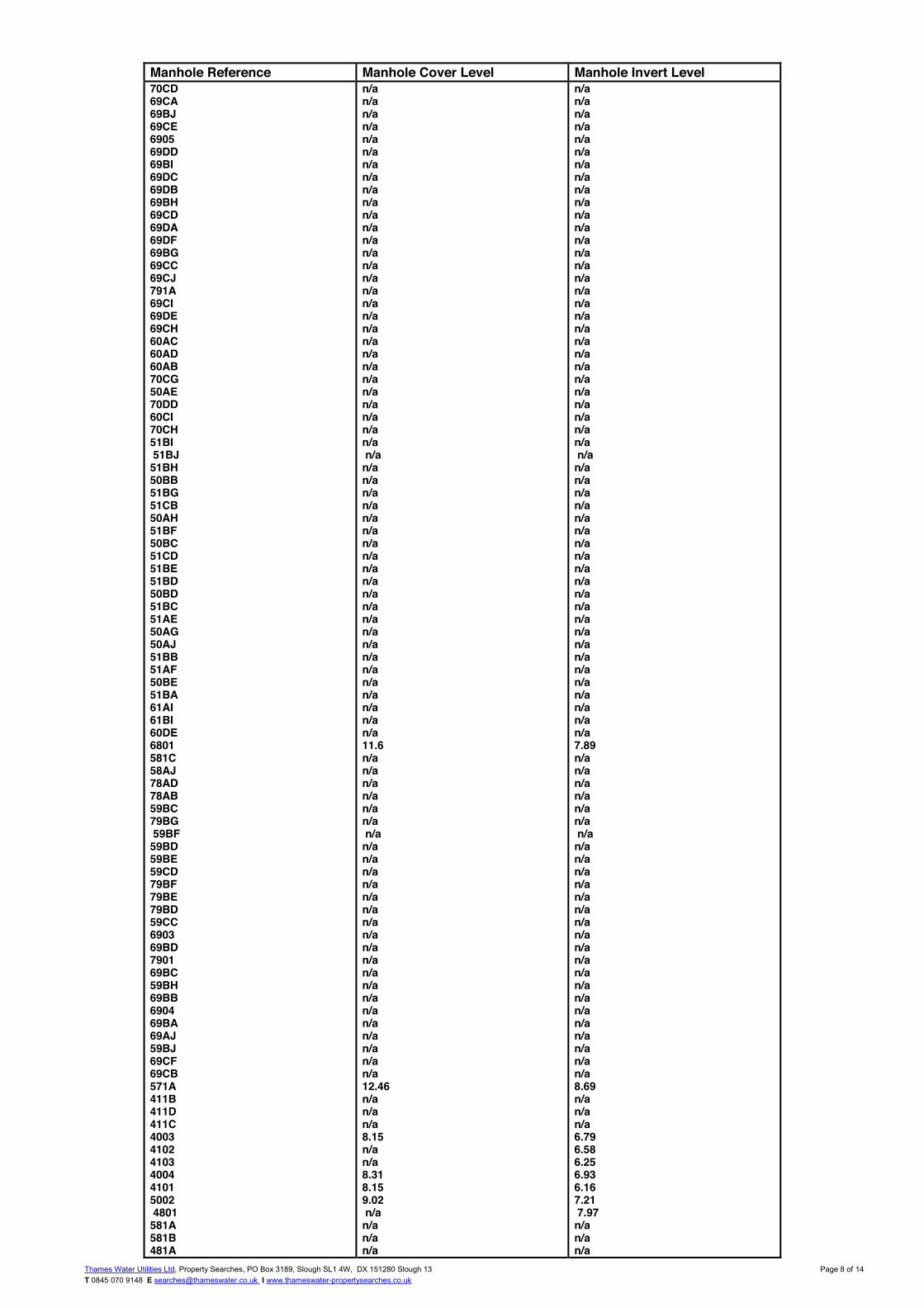
Thames Water Utilities Ltd, Property Searches, PO Box 3189, Slough SL1 4W, DX 151280 Slough 13 T 0845 070 9148 E [email protected] I www.thameswater-propertysearches.co.uk
Page 8 of 14
Manhole Reference Manhole Cover Level Manhole Invert Level 70CD 69CA 69BJ 69CE 6905 69DD 69BI 69DC 69DB 69BH 69CD 69DA 69DF 69BG 69CC 69CJ 791A 69CI 69DE 69CH 60AC 60AD 60AB 70CG 50AE 70DD 60CI 70CH 51BI 51BJ 51BH 50BB 51BG 51CB 50AH 51BF 50BC 51CD 51BE 51BD 50BD 51BC 51AE 50AG 50AJ 51BB 51AF 50BE 51BA 61AI 61BI 60DE 6801 581C 58AJ 78AD 78AB 59BC 79BG 59BF 59BD 59BE 59CD 79BF 79BE 79BD 59CC 6903 69BD 7901 69BC 59BH 69BB 6904 69BA 69AJ 59BJ 69CF 69CB 571A 411B 411D 411C 4003 4102 4103 4004 4101 5002 4801 581A 581B 481A
n/a n/a n/a n/a n/a n/a n/a n/a n/a n/a n/a n/a n/a n/a n/a n/a n/a n/a n/a n/a n/a n/a n/a n/a n/a n/a n/a n/a n/a n/a n/a n/a n/a n/a n/a n/a n/a n/a n/a n/a n/a n/a n/a n/a n/a n/a n/a n/a n/a n/a n/a n/a 11.6 n/a n/a n/a n/a n/a n/a n/a n/a n/a n/a n/a n/a n/a n/a n/a n/a n/a n/a n/a n/a n/a n/a n/a n/a n/a n/a 12.46 n/a n/a n/a 8.15 n/a n/a 8.31 8.15 9.02 n/a n/a n/a n/a
n/a n/a n/a n/a n/a n/a n/a n/a n/a n/a n/a n/a n/a n/a n/a n/a n/a n/a n/a n/a n/a n/a n/a n/a n/a n/a n/a n/a n/a n/a n/a n/a n/a n/a n/a n/a n/a n/a n/a n/a n/a n/a n/a n/a n/a n/a n/a n/a n/a n/a n/a n/a 7.89 n/a n/a n/a n/a n/a n/a n/a n/a n/a n/a n/a n/a n/a n/a n/a n/a n/a n/a n/a n/a n/a n/a n/a n/a n/a n/a 8.69 n/a n/a n/a 6.79 6.58 6.25 6.93 6.16 7.21 7.97 n/a n/a n/a

Thames Water Utilities Ltd, Property Searches, PO Box 3189, Slough SL1 4W, DX 151280 Slough 13 T 0845 070 9148 E [email protected] I www.thameswater-propertysearches.co.uk
Page 9 of 14
Manhole Reference Manhole Cover Level Manhole Invert Level 58AH 58AI 59BB 59BI 5902 5901 501B 501C 501A 4701
n/a n/a n/a n/a n/a 10.83 n/a n/a n/a 12.29
n/a n/a n/a n/a n/a 8.76 n/a n/a n/a 8.93
The position of the apparatus shown on this plan is given without obligation and warranty, and the accuracy cannot be guaranteed. Service pipes are not shown but their presence should be anticipated. No liability of any kind whatsoever is accepted by Thames Water for any error or omission. The actual position of mains and services must be verified and established on site before any works are undertaken.

Thames Water Utilities Ltd, Property Searches, PO Box 3189, Slough SL1 4W, DX 151280 Slough 13 T 0845 070 9148 E [email protected] I www.thameswater-propertysearches.co.uk
Page 10 of 14
ALS Sewer Map Key
Foul: A sewer designed to convey waste water from domestic andindustrial sources to a treatment works.
Surface Water: A sewer designed to convey surface water (e.g. rainwater from roofs, yards and car parks) to rivers or watercourses.
Combined: A sewer designed to convey both waste water and surfacewater from domestic and industrial sources to a treatment works.
Trunk Surface Water
Storm Relief
Vent Pipe
Proposed Thames SurfaceWater Sewer
Gallery
Surface Water RisingMain
Sludge Rising Main
Vacuum
Public Sewer Types (Operated & Maintained by Thames Water)
Notes:1) All levels associated with the plans are to Ordnance Datum Newlyn.2) All measurements on the plans are metric.3) Arrows (on gravity fed sewers) or flecks (on rising mains) indicate direction of
flow.4) Most private pipes are not shown on our plans, as in the past, this information has
not been recorded.5) ‘na’ or ‘0’ on a manhole level indicates that data is unavailable.
Trunk Foul
Trunk Combined
Bio-solids (Sludge)
Proposed Thames WaterFoul Sewer
Foul Rising Main
Combined Rising Main
Proposed Thames WaterRising Main
Sewer FittingsA feature in a sewer that does not affect the flow in the pipe. Example: a ventis a fitting as the function of a vent is to release excess gas.
Operational ControlsA feature in a sewer that changes or diverts the flow in the sewer. Example:A hydrobrake limits the flow passing downstream.
Air Valve
Dam Chase
Fitting
Meter
Vent Column
Control Valve
Drop Pipe
Ancillary
Weir
End ItemsEnd symbols appear at the start or end of a sewer pipe. Examples: anUndefined End at the start of a sewer indicates that Thames Water has noknowledge of the position of the sewer upstream of that symbol, Outfall on asurface water sewer indicates that the pipe discharges into a stream or river.
Outfall
Undefined End
Inlet
Other SymbolsSymbols used on maps which do not fall under other general categories
Summit
Public/Private Pumping Station/
Invert Level
Change of characteristic indicator (C.O.C.I.)
Other Sewer Types (Not Operated or Maintained by Thames Water)
AreasLines denoting areas of underground surveys, etc.
Agreement
Chamber
Operational Site
Conduit Bridge
Foul Sewer
Combined Sewer
Culverted Watercourse
Surface Water Sewer
Gulley
Proposed
Abandoned Sewer
Tunnel
6) The text appearing alongside a sewer line indicates the internal diameter ofthe pipe in milimetres. Text next to a manhole indicates the manholereference number and should not be taken as a measurement. If you areunsure about any text or symbology present on the plan, please contact amember of Property Insight on 0845 070 9148.
P P
M
W

Thames Water Utilities Ltd, Property Searches, PO Box 3189, Slough SL1 4W, DX 151280 Slough 13 T 0845 070 9148 E [email protected] I www.thameswater-propertysearches.co.uk
Page 11 of 14
Asset Location Search Water Map - ALS/ALS Standard/2018_3859399
The width of the displayed area is 500 m and the centre of the map is located at OS coordinates 531669, 175938. The position of the apparatus shown on this plan is given without obligation and warranty, and the accuracy cannot be guaranteed. Service pipes are not shown but their presence should be anticipated. No liability of any kind whatsoever is accepted by Thames Water for any error or omission. The actual position of mains and services must be verified and established on site before any works are undertaken. Based on the Ordnance Survey Map with the Sanction of the controller of H.M. Stationery Office, License no. 100019345 Crown Copyright Reserved.
6'' CI
3'' CI
10"
4"
4"
3"
3"
4"
100mm
3"
3"
6"
5"
6"
3"
100mm
5"
3"
4"
3"
3"
4"
100mm
100m
m
10"
5"
6"
6"
100 mm
PR
OP
OS
ED
# 118 76
6"
6"
100mm
4"
3"
4"
3"
100mm PROPOSED #1512
125mm
3"
7"
4"
125mm
-->
4"
3"
4"
100m
m
125mm
4"
6"
3"
5"
4"
6"
3"
3"
NOV 1989
3"
90mm
100m
m
100mm LAID
3"
16" T
RU
NK
D
D
D
D
D
D
D
D
D
(
(
(
(
(
(
(
(
(
(
(
(
(
(
(
(
(
(
(
(
(
(
(
(
(
(
(
(
(
(
(
(
(
(
(
(
(
(
(
(
(
(
(
(
(
(
(
(
(
(
(
(
(
(
(
(
(
(
(
(
(
(
(
(
(
(
(
(
(
(
(
(
(
(
(
(
(
(
(
(
(
(
(
(
(
(
(
(
(
(
(
(
á
á
%
á
á
á
á
á
±
±
á
%
á
á
á
á
%±
á
á
á
á
!
!
!
!
!
!
!
!
!
!
!
!
!
!
!
!
!
!
!
!
!
!
!
!
!
!
!
!
!
!
!
!
!
!
!
!
!
!
!
!
!
!
!
!
!
!
!
!!
!
!
!
!
!
!
!
!
!
!
!
!
¤
¤
¤
¤
¤
¤
¤
¤
¤
¤¤
¤
¤
¤
¤
¤
¤
¤
¤
¤
¤
¤ ¤
¤
¤
¤
¤
¤
¤
¤
¤
¤
¤
¤
¤
¤
¤
¤
¤
¤
¤
¤
¤
¤
¤
¤
¤
¤
¤
¤
¤
¤
¤
¤
¤
¤
¤
¤
¤
¤
¤
¤
¤
¤
¤
¤
¤
¤
¤
¤
¤
¤
¤
¤
¤
¤¤
¤
¤ ¤
¤
¤
¤
¤
¤
31
2
6
94
8
7
5
PH
Youth
Court
Viaduct
toEl
Wyck Gardens
Elmore House
Harris House
Secker House
Kemble House
St John's Church
Woolley House
Ashby House
Nevil H
ouse
Howard House
New
ark House
11
ANGELL ROAD
Hopton H
ouse
Kettleby House
Edgehill House
Newbury House
Langport House
Barrington Lodge
BARRINGTO
N ROAD
Eldon House
Games Courts
LOUGHBOROUGH ROAD
Harper H
ouse
Leicester House
9.8m
9.4m
9.9m
10
63
14
57
26
46
61
37
382842
31
32
51
2a
24
16
23
19
30
36
82
12
5043
53
17
40
18
49 41
15
71
22
54
70
6639
65
33
62
34
5245
78
13
1a
56
27
20
67
25
60
92
88
21
94
48
44
59
47
55
58
8179
13.2m
12.4m 12.3m
10.1m
13.3m
LB
SL
Ps
Works
113
CLO
SE
Yard
ELA
M
Sta
165
169
167
166
173
214
244
158
156
218
227
103
239
223
213
228
142
234
150
148
215217
242
189
152
155
210
226
102
236240
168160
181
101
237
Station A
venue
HINTON ROAD
BELINDA
ROAD
167a
169a
RUPERT GARDENSM
INET R
OAD
MA
JOR
CLO
SE
RIDGW
AY R
OAD
RAT
HG
AR R
OAD
GORDON GROVE
FEATLEY RO
AD
HILDA LOCKERT WALK
STYLES GARDENS
SWINFORD GARDENS
WIC
KW
OO
D S
TRE
ET
ANGELL PARK GARDENS
6 to 9
1 to 8ST JAMES'S CRESCENT
FIV
EW
AYS
RO
AD
TCB
TCBs
Surgery
1 to 12
4 to
16
9 to 20
1 to 78
9 to 25
5 to
10
1 to 13
11 to
22
26 to 42
21 to 32
32 to 35
1a to 1h 3a to 3h
41 to
52
28 to 31
20 to 23
33 to 44
28 to
35
14 to 2627 to 39
Sub Sta
House
219
to 2
23
150 to 160
Playground
St John's Angell Town
El Sub S
ta
Games Court
Primary School
Adventure Playground
Hughes Terrace
16
25
51
26
10
30
Playground70
12
36
46
12
46
1
7
TCBs
6
9
TCBs
LB
50
18
31
21
36
1
10
25
4
3
26 to 42
48
51
23
12
41
2
22
24
1
2
23
1
1928
1
17
41
17
26
16
El
62
11
10
El S
ub S
ta
Playground
11
Playground
8
3
to
TCB
1
ANGELL ROAD
33
63
1
7
9
24
22
15
27
40
23
19
36
1
52
14
20
3
2
6
213to
El Sub Sta
3626
38
26
942
27
16
Playground
103
18
1
El Sub Sta
21
8
5043
LB
20
25
60
14
17
10
37
78
2
6
1024
22
19
Games Courts
9
10.1mCentre
Amberley
74
35
86
25
73
225
153
154
151
238
209
63
War
rior C
ourt
Sub
Scrap
TON ROAD
1 to 3
1 to
4
1 to
4
1 to 5
MALLAM
S MEW
S
1 to 53
1 to 53
1 to 53
1 to 53
1 to 88
1 to 88
1 to 78
1 to 10
1 to 80
1 to
14
1 to 18
Mar
ston
Hou
se
Church of England
Hughes Terrace
Schoolkeepers
Henry House
59
83
reatment
12
to
18
10
2
44
El
71
E
to
GH
BOR
OU
GH
RO
AD
to
to
39
Sub
13
32
to
Sub Sta
17
PH
19
to
42
to
to
33
to
1
11
5
16
4
17
12
16
47
31
1
38
18
32
to
10
40
to
19
16
17
45
11
1
to
to
4
446
28
18
1
16
to
to
38
18
15

Thames Water Utilities Ltd, Property Searches, PO Box 3189, Slough SL1 4W, DX 151280 Slough 13 T 0845 070 9148 E [email protected] I www.thameswater-propertysearches.co.uk
Page 12 of 14
ALS Water Map Key
PIPE DIAMETER DEPTH BELOW GROUND
Up to 300mm (12”) 900mm (3’)
300mm - 600mm (12” - 24”) 1100mm (3’ 8”)
600mm and bigger (24” plus) 1200mm (4’)
DistributionMain: The most common pipe shown on water maps.With few exceptions, domestic connections are only made todistribution mains.
Trunk Main: A main carrying water from a source of supply to atreatmentplant or reservoir, or from one treatmentplant or reservoirto another. Also a main transferring water in bulk to smaller watermains used for supplying individual customers.
Supply Main: A supply main indicates that the water main is usedas a supply for a single property or group of properties.
Fire Main: Where a pipe is used as a fire supply, the word FIRE willbe displayed along the pipe.
Metered Pipe: A metered main indicates that the pipe in questionsupplies water for a single property or group of properties and thatquantity of water passing through the pipe is metered even thoughthere may be no meter symbol shown.
Transmission Tunnel: A very large diameter water pipe. Mosttunnels are buried very deep underground. These pipes are notexpected to affect the structural integrity of buildingsshown on themap provided.
ProposedMain: A main that is still in the planningstages or in theprocess of being laid. More details of the proposed main and itsreference number are generally included near the main.
Water Pipes (Operated & Maintained by Thames Water)
HydrantsSingle Hydrant
MetersMeter
ValvesGeneral PurposeValve
Air Valve
End ItemsٞSymbol indicating what happens at the end of
a water main.
Blank Flange
Capped End
Undefined End
Manifold
Customer Supply
Fire Supply
Emptying Pit
Operational SitesBooster Station
Other
Other (Proposed)
Pumping Station
Service Reservoir
Shaft Inspection
TreatmentWorks
Unknown
Other Symbols
Other Water Pipes (Not Operated or Maintained by Thames Water)
Data Logger
Other Water Company Main: Occasionally other water companywater pipes may overlap the border of our clean water coveragearea. These mains are denoted in purple and in most cases havethe owner of the pipe displayed along them.
Private Main: Indiates that the water main in question is not ownedby Thames Water. These mains normally have text associated withthem indicating the diameter and owner of the pipe.
3” SUPPLY
3” FIRE
3” METERED
L
CF
4”
16”
Water Tower
?
Pressure ControlValve
CustomerValve

Structural and Civil Engineering Services W02047 Hero of Switerland, Loughborough Junction, London 22 www.swh.co.uk
London Bedford
Winchester
Appendix C Existing Site Layout

!
UNIDENTIFIED
HEATING PIPESSERVICE DUCTS
VAPOUR RECOVERYGAUGE LINEOFFSET FILL PIPEVENT PIPEFUEL PIPEPUMPING MAINCOMBINED DRAINAGESURFACE DRAINAGECONTAMINATED SURFACEFOUL DRAINAGEGAS PIPEWATER PIPECOMMUNICATION CABLECABLE TELEVISIONTELECOMS CABLE
ELECTRIC CABLE
UTILITY KEY
ELECTRIC & COMMS CABLE
TRAFFIC SIGNAL CABLE
SURVEY BOUNDARY
TRENCH SCARGROUND DEPRESSION
EARTHING ROD / CABLE
END OF TRACECABLE / PIPE RISER
BACKDROP / TRAPPED EXIT HEAD OF RUN / CAPPED
PIPE INLET / OUTFALLDRAINAGE VALVE
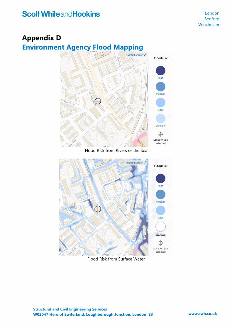
Structural and Civil Engineering Services W02047 Hero of Switerland, Loughborough Junction, London 23 www.swh.co.uk
London Bedford
Winchester
Appendix D Environment Agency Flood Mapping
Flood Risk from Rivers or the Sea
Flood Risk from Surface Water

Structural and Civil Engineering Services W02047 Hero of Switerland, Loughborough Junction, London 24 www.swh.co.uk
London Bedford
Winchester
Appendix E Proposed Site Layout

UP
UP
UPDN
ResidentialStaircase
flue riser
PublicHouse
dumbwaiter
1500
StoreStore
ResidentialBin Store
ResidentialLobby
Sliding doors
WC
Sliding doors
PublicHouse Bin
StoreSubstation
WORK IN PROGRESS
date revision note drawn checkedrev
N
© Gensler All rights reserved, including but not limited to The Copyright, Design and Patents Act 1988
key plan
category
project
client
2016
number rev
rev drawn checkedscale
family
project number
notes:Do not scale from drawings. All discrepancies to be reported to Gensler architect immediately.All dimensions to be verified by contractor on site prior to any works
lead consultant
consultant
title
ISSUED DATE: 13/08/18
Tel +44 (0)20 7073 9600Fax +44 (0)20 7539 1917
Aldgate House33 Aldgate High StreetLondon, EC3N 1AHUnited Kingdom
UDN Properties65 Delamere Road, HayesMiddlesex UB4 0NNUKTel 020 3726 9801
1 : 100
15/0
4/20
19 1
4:19
:31
\\gen
sler .a
d\Pr
ojects
\Rev
itUse
rMod
els\2
4746
\Arc
hitec
ture
- 08
. 736
9.00
0_Lu
ke_A
skwi
th@
gens
ler.c o
m.rv
t
CA1.201
PROPOSED GROUND FLOOR PLAN
08.7369.000
Hero of SwitzerlandSW9 7LL
1 GENERAL ARRANGEMENT
200-299 ENLARGED PLANS PARTITION
02/04/19 NLLA
A 06/03/19 Draft Issue LA NLB 02/04/19 Planning Issue LA NLC 15/04/19 Planning Issue LA NL
SCALE: 1 : 100PROPOSED GROUND FLOOR1

Structural and Civil Engineering Services W02047 Hero of Switerland, Loughborough Junction, London 25 www.swh.co.uk
London Bedford
Winchester
Appendix F MicroDrainage Existing Site Discharge Rates

Scott-White & Hookins Page 142 West Street W02047London House Hero of SwitzerlandCarshalton SM5 2PR Existing Runoff RatesDate 03/09/2018 16:13 Designed by HHFile W0247 Existing runoff Rates.MDX Checked byMicro Drainage Network 2018.1
STORM SEWER DESIGN by the Modified Rational Method
Design Criteria for Storm
©1982-2018 Innovyze
Pipe Sizes STANDARD Manhole Sizes STANDARD
FSR Rainfall Model - England and WalesReturn Period (years) 100 PIMP (%) 100
M5-60 (mm) 20.100 Add Flow / Climate Change (%) 0Ratio R 0.436 Minimum Backdrop Height (m) 0.200
Maximum Rainfall (mm/hr) 50 Maximum Backdrop Height (m) 1.500Maximum Time of Concentration (mins) 30 Min Design Depth for Optimisation (m) 1.200
Foul Sewage (l/s/ha) 0.000 Min Vel for Auto Design only (m/s) 1.00Volumetric Runoff Coeff. 0.750 Min Slope for Optimisation (1:X) 500
Designed with Level Soffits
Time Area Diagram for Storm
Time(mins)
Area(ha)
Time(mins)
Area(ha)
0-4 0.043 4-8 0.002
Total Area Contributing (ha) = 0.045
Total Pipe Volume (m³) = 0.532
Network Design Table for Storm
PN Length(m)
Fall(m)
Slope(1:X)
I.Area(ha)
T.E.(mins)
BaseFlow (l/s)
k(mm)
HYDSECT
DIA(mm)
Section Type AutoDesign
S1.000 22.772 0.500 45.5 0.023 4.00 0.0 0.600 o 150 Pipe/ConduitS1.001 7.313 0.320 22.9 0.022 0.00 0.0 0.600 o 150 Pipe/Conduit
Network Results Table
PN Rain(mm/hr)
T.C.(mins)
US/IL(m)
Σ I.Area(ha)
Σ BaseFlow (l/s)
Foul(l/s)
Add Flow(l/s)
Vel(m/s)
Cap(l/s)
Flow(l/s)
S1.000 50.00 4.25 10.500 0.023 0.0 0.0 0.0 1.49 26.4 3.1S1.001 50.00 4.31 10.000 0.045 0.0 0.0 0.0 2.12 37.4 6.1

Scott-White & Hookins Page 242 West Street W02047London House Hero of SwitzerlandCarshalton SM5 2PR Existing Runoff RatesDate 03/09/2018 16:13 Designed by HHFile W0247 Existing runoff Rates.MDX Checked byMicro Drainage Network 2018.1
Area Summary for Storm
©1982-2018 Innovyze
PipeNumber
PIMPType
PIMPName
PIMP(%)
GrossArea (ha)
Imp.Area (ha)
Pipe Total(ha)
1.000 - - 100 0.023 0.023 0.0231.001 - - 100 0.022 0.022 0.022
Total Total Total0.045 0.045 0.045
Free Flowing Outfall Details for Storm
OutfallPipe Number
OutfallName
C. Level(m)
I. Level(m)
MinI. Level
(m)
D,L(mm)
W(mm)
S1.001 S 10.740 9.680 7.320 0 0
Simulation Criteria for Storm
Volumetric Runoff Coeff 0.750 Additional Flow - % of Total Flow 0.000Areal Reduction Factor 1.000 MADD Factor * 10m³/ha Storage 2.000
Hot Start (mins) 0 Inlet Coeffiecient 0.800Hot Start Level (mm) 0 Flow per Person per Day (l/per/day) 0.000
Manhole Headloss Coeff (Global) 0.500 Run Time (mins) 60Foul Sewage per hectare (l/s) 0.000 Output Interval (mins) 1
Number of Input Hydrographs 0 Number of Offline Controls 0 Number of Time/Area Diagrams 0Number of Online Controls 0 Number of Storage Structures 0 Number of Real Time Controls 0
Synthetic Rainfall Details
Rainfall Model FSR Profile Type SummerReturn Period (years) 100 Cv (Summer) 0.750
Region England and Wales Cv (Winter) 0.840M5-60 (mm) 20.100 Storm Duration (mins) 30
Ratio R 0.436

Scott-White & Hookins Page 342 West Street W02047London House Hero of SwitzerlandCarshalton SM5 2PR Existing Runoff RatesDate 03/09/2018 16:13 Designed by HHFile W0247 Existing runoff Rates.MDX Checked byMicro Drainage Network 2018.1
1 year Return Period Summary of Critical Results by Maximum Outflow (Rank 1) for Storm
©1982-2018 Innovyze
Simulation CriteriaAreal Reduction Factor 1.000 Additional Flow - % of Total Flow 0.000
Hot Start (mins) 0 MADD Factor * 10m³/ha Storage 2.000Hot Start Level (mm) 0 Inlet Coeffiecient 0.800
Manhole Headloss Coeff (Global) 0.500 Flow per Person per Day (l/per/day) 0.000Foul Sewage per hectare (l/s) 0.000
Number of Input Hydrographs 0 Number of Offline Controls 0 Number of Time/Area Diagrams 0Number of Online Controls 0 Number of Storage Structures 0 Number of Real Time Controls 0
Synthetic Rainfall DetailsRainfall Model FSR M5-60 (mm) 20.000 Cv (Summer) 0.750
Region England and Wales Ratio R 0.432 Cv (Winter) 0.840
Margin for Flood Risk Warning (mm) 300.0 DVD Status OFFAnalysis Timestep Fine Inertia Status OFF
DTS Status ON
Profile(s) Summer and WinterDuration(s) (mins) 15, 30, 60, 120, 180, 240, 360, 480, 600, 720, 960,
1440Return Period(s) (years) 1, 30, 100
Climate Change (%) 0, 0, 0
PNUS/MHName Storm
ReturnPeriod
ClimateChange
First (X)Surcharge
First (Y)Flood
First (Z)Overflow
OverflowAct.
Water Level(m)
SurchargedDepth(m)
FloodedVolume(m³)
S1.000 S1 15 Winter 1 +0% 10.537 -0.113 0.000S1.001 S2 15 Winter 1 +0% 10.045 -0.105 0.000
PNUS/MHName
Flow /Cap.
Overflow(l/s)
PipeFlow(l/s) Status
LevelExceeded
S1.000 S1 0.14 3.5 OKS1.001 S2 0.19 6.2 OK

Scott-White & Hookins Page 442 West Street W02047London House Hero of SwitzerlandCarshalton SM5 2PR Existing Runoff RatesDate 03/09/2018 16:13 Designed by HHFile W0247 Existing runoff Rates.MDX Checked byMicro Drainage Network 2018.1
30 year Return Period Summary of Critical Results by Maximum Outflow (Rank 1) for Storm
©1982-2018 Innovyze
Simulation CriteriaAreal Reduction Factor 1.000 Additional Flow - % of Total Flow 0.000
Hot Start (mins) 0 MADD Factor * 10m³/ha Storage 2.000Hot Start Level (mm) 0 Inlet Coeffiecient 0.800
Manhole Headloss Coeff (Global) 0.500 Flow per Person per Day (l/per/day) 0.000Foul Sewage per hectare (l/s) 0.000
Number of Input Hydrographs 0 Number of Offline Controls 0 Number of Time/Area Diagrams 0Number of Online Controls 0 Number of Storage Structures 0 Number of Real Time Controls 0
Synthetic Rainfall DetailsRainfall Model FSR M5-60 (mm) 20.000 Cv (Summer) 0.750
Region England and Wales Ratio R 0.432 Cv (Winter) 0.840
Margin for Flood Risk Warning (mm) 300.0 DVD Status OFFAnalysis Timestep Fine Inertia Status OFF
DTS Status ON
Profile(s) Summer and WinterDuration(s) (mins) 15, 30, 60, 120, 180, 240, 360, 480, 600, 720, 960,
1440Return Period(s) (years) 1, 30, 100
Climate Change (%) 0, 0, 0
PNUS/MHName Storm
ReturnPeriod
ClimateChange
First (X)Surcharge
First (Y)Flood
First (Z)Overflow
OverflowAct.
Water Level(m)
SurchargedDepth(m)
FloodedVolume(m³)
S1.000 S1 15 Summer 30 +0% 10.561 -0.089 0.000S1.001 S2 15 Winter 30 +0% 10.077 -0.073 0.000
PNUS/MHName
Flow /Cap.
Overflow(l/s)
PipeFlow(l/s) Status
LevelExceeded
S1.000 S1 0.35 8.6 OKS1.001 S2 0.53 16.9 OK

Scott-White & Hookins Page 542 West Street W02047London House Hero of SwitzerlandCarshalton SM5 2PR Existing Runoff RatesDate 03/09/2018 16:13 Designed by HHFile W0247 Existing runoff Rates.MDX Checked byMicro Drainage Network 2018.1
100 year Return Period Summary of Critical Results by Maximum Outflow (Rank 1) for Storm
©1982-2018 Innovyze
Simulation CriteriaAreal Reduction Factor 1.000 Additional Flow - % of Total Flow 0.000
Hot Start (mins) 0 MADD Factor * 10m³/ha Storage 2.000Hot Start Level (mm) 0 Inlet Coeffiecient 0.800
Manhole Headloss Coeff (Global) 0.500 Flow per Person per Day (l/per/day) 0.000Foul Sewage per hectare (l/s) 0.000
Number of Input Hydrographs 0 Number of Offline Controls 0 Number of Time/Area Diagrams 0Number of Online Controls 0 Number of Storage Structures 0 Number of Real Time Controls 0
Synthetic Rainfall DetailsRainfall Model FSR M5-60 (mm) 20.000 Cv (Summer) 0.750
Region England and Wales Ratio R 0.432 Cv (Winter) 0.840
Margin for Flood Risk Warning (mm) 300.0 DVD Status OFFAnalysis Timestep Fine Inertia Status OFF
DTS Status ON
Profile(s) Summer and WinterDuration(s) (mins) 15, 30, 60, 120, 180, 240, 360, 480, 600, 720, 960,
1440Return Period(s) (years) 1, 30, 100
Climate Change (%) 0, 0, 0
PNUS/MHName Storm
ReturnPeriod
ClimateChange
First (X)Surcharge
First (Y)Flood
First (Z)Overflow
OverflowAct.
Water Level(m)
SurchargedDepth(m)
FloodedVolume(m³)
S1.000 S1 15 Winter 100 +0% 10.570 -0.080 0.000S1.001 S2 15 Summer 100 +0% 10.092 -0.058 0.000
PNUS/MHName
Flow /Cap.
Overflow(l/s)
PipeFlow(l/s) Status
LevelExceeded
S1.000 S1 0.45 11.2 OKS1.001 S2 0.69 22.0 OK

Structural and Civil Engineering Services W02047 Hero of Switerland, Loughborough Junction, London 26 www.swh.co.uk
London Bedford
Winchester
Appendix G Proposed Drainage Strategy

UP
UP
UP
DN
Residential
Staircas
e
flue riser Public
House
dumbwaiter
1500
Store
Store
Residential
Bin Store
Residential
Lobby
Sliding doors
WC
Sliding doors
Public
House Bin
Store
Substation
FEATLEY
ROAD
150 to 160
21
1 to 53
Leicester House
Key
Proposed FW Sewer
Proposed SW Sewer
Proposed Combined Sewer
Existing Combined Sewer
Existing FW Sewer
Existing SW Sewer
Proposed Attenuation Tank
Sewer to be Abandoned
CP004-01_FM_ST_008_D
Drn.Rev.Project
Drawing
Amendment Chkd. Appd. Date
Scale at A1 -
Client
The Hero of SwitzerlandBrixton, London
Proposed Drainage Strategy
1:
DO NOT SCALE FROM THIS DRAWING
Notes
Harman House, Andover Road, Winchester, Hampshire SO23 7BST: +44 (0)1962 844855 W: www.swh.co.uk E: [email protected]
StructuralEngineering
CivilEngineering
Sustainabilityand BREEAM
CDMConsultancy
PRELIMINARY - NOT FOR CONSTRUCTION
W02047-SWH-XX-XX-DR-C-0500-P04100
Macniven Quays Ltd
Preliminary
Project Originator Zone Level Type Role Number Rev.
P01 Preliminary HH HJH RH 04.09.18
DRAINAGE
x Any information given on this drawing regarding existing servicesis believed to be correct. The contractor must check thisinformation and determine the nature and location of other existingservices from the various statutory authorities before commencingexcavation works.
x Drainage works to be constructed in accordance with BS EN 752and Approved Document H
x All soft spots and unacceptable material encountered in drainageexcavations is to be removed and replaced with granular materialto the requirements of the building control officer.
x Pipes to be installed to manufacturers recommendations.
x Pipes under buildings to be laid to a fall of 1:40 minimum unlessnoted otherwise.
x Plastic plain wall pipes to be PVC-U to BS EN 1401-1, class SN4,with flexible joints, Kitemark certified. Structured wall plastic pipesto be to WIS 04-35-01, Kitemark certified
x Clay pipes to be vitrified clay to BS EN 295-1, with flexible joints,Kitemark certified. Clayware pipes must be extra strengthclassification protected in accordance with the specified details.
x Concrete pipes to be precast concrete to BS 5911-1 and BS EN1916, with flexible joints.
x Bedding of pipes to be in accordance with approved document H1.
x Rocker pipes with flexible joints are to be provided at a distance of150mm and 750mm from the face of construction to manholes,where pipes pass above, below or through ground beams orfoundations; at gully connections and soil stack ends.
x Manhole access covers are to be located at the outgoing side ofmanholes.
x Cover levels are to be fixed on site to suit finished levels. Coversand frames to BS EN124, Grade D to be used in areas subject toheavy vehicular loading, Grade C in areas subject to lightvehicular loading and Grade B to be used elsewhere.
GENERAL
x This drawing is to be read in conjunction with all relevantEngineers and Architects drawings and with the Specification.
x For setting out refer to Architects drawings.
x All dimensions are in millimetres and levels are in metres unlessnoted otherwise.
x Contractor to take all relevant dimensions on site. Anydiscrepancies to be advised to the Engineer.
x Contractor to check/scan for services prior to construction to avoidany damage during works.
P02 Updated To Suit Latest Site Layout HH HJH RH 26.02.19
P03 Updated To Suit Latest Site Layout CLL HJH RH 05.04.19
P04 Updated To Suit Latest Site Layout CLL HJH RH 15.04.19

Structural and Civil Engineering Services W02047 Hero of Switerland, Loughborough Junction, London 27 www.swh.co.uk
London Bedford
Winchester
Appendix H MicroDrainage Attenuation Calculations

Scott-White & Hookins Page 142 West Street W02047London House Hero of SwitzerlandCarshalton SM5 2PR Attenuation CalcsDate 03/09/2018 17:45 Designed by HHFile W02047 Attenuation Calcs.SRCX Checked byMicro Drainage Source Control 2018.1
Summary of Results for 100 year Return Period (+40%)
©1982-2018 Innovyze
Half Drain Time : 20 minutes.
StormEvent
MaxLevel(m)
MaxDepth(m)
MaxInfiltration
(l/s)
MaxControl(l/s)
MaxΣ Outflow(l/s)
MaxVolume(m³)
Status
15 min Summer 10.297 0.297 0.0 5.0 5.0 9.0 O K30 min Summer 10.336 0.336 0.0 5.0 5.0 10.2 O K60 min Summer 10.331 0.331 0.0 5.0 5.0 10.1 O K120 min Summer 10.266 0.266 0.0 5.0 5.0 8.1 O K180 min Summer 10.203 0.203 0.0 5.0 5.0 6.2 O K240 min Summer 10.157 0.157 0.0 5.0 5.0 4.8 O K360 min Summer 10.114 0.114 0.0 4.6 4.6 3.5 O K480 min Summer 10.097 0.097 0.0 3.8 3.8 2.9 O K600 min Summer 10.086 0.086 0.0 3.3 3.3 2.6 O K720 min Summer 10.079 0.079 0.0 2.8 2.8 2.4 O K960 min Summer 10.069 0.069 0.0 2.3 2.3 2.1 O K1440 min Summer 10.057 0.057 0.0 1.7 1.7 1.7 O K2160 min Summer 10.048 0.048 0.0 1.2 1.2 1.4 O K2880 min Summer 10.042 0.042 0.0 1.0 1.0 1.3 O K4320 min Summer 10.035 0.035 0.0 0.7 0.7 1.1 O K5760 min Summer 10.031 0.031 0.0 0.5 0.5 0.9 O K7200 min Summer 10.028 0.028 0.0 0.5 0.5 0.9 O K8640 min Summer 10.026 0.026 0.0 0.4 0.4 0.8 O K10080 min Summer 10.024 0.024 0.0 0.3 0.3 0.7 O K
15 min Winter 10.340 0.340 0.0 5.0 5.0 10.3 O K30 min Winter 10.380 0.380 0.0 5.0 5.0 11.5 O K60 min Winter 10.364 0.364 0.0 5.0 5.0 11.1 O K120 min Winter 10.261 0.261 0.0 5.0 5.0 7.9 O K180 min Winter 10.170 0.170 0.0 5.0 5.0 5.2 O K
StormEvent
Rain(mm/hr)
FloodedVolume(m³)
DischargeVolume(m³)
Time-Peak(mins)
15 min Summer 141.917 0.0 12.0 1530 min Summer 91.958 0.0 15.5 2560 min Summer 56.713 0.0 19.1 42120 min Summer 33.812 0.0 22.8 74180 min Summer 24.675 0.0 25.0 104240 min Summer 19.628 0.0 26.5 134360 min Summer 14.150 0.0 28.6 188480 min Summer 11.224 0.0 30.3 248600 min Summer 9.372 0.0 31.6 308720 min Summer 8.084 0.0 32.7 370960 min Summer 6.399 0.0 34.5 4901440 min Summer 4.596 0.0 37.2 7342160 min Summer 3.296 0.0 40.0 11002880 min Summer 2.602 0.0 42.1 14684320 min Summer 1.862 0.0 45.2 21885760 min Summer 1.467 0.0 47.5 28647200 min Summer 1.219 0.0 49.3 36488640 min Summer 1.047 0.0 50.9 440010080 min Summer 0.921 0.0 52.2 5024
15 min Winter 141.917 0.0 13.4 1630 min Winter 91.958 0.0 17.4 2660 min Winter 56.713 0.0 21.4 46120 min Winter 33.812 0.0 25.5 80180 min Winter 24.675 0.0 28.0 108

Scott-White & Hookins Page 242 West Street W02047London House Hero of SwitzerlandCarshalton SM5 2PR Attenuation CalcsDate 03/09/2018 17:45 Designed by HHFile W02047 Attenuation Calcs.SRCX Checked byMicro Drainage Source Control 2018.1
Summary of Results for 100 year Return Period (+40%)
©1982-2018 Innovyze
StormEvent
MaxLevel(m)
MaxDepth(m)
MaxInfiltration
(l/s)
MaxControl(l/s)
MaxΣ Outflow(l/s)
MaxVolume(m³)
Status
240 min Winter 10.121 0.121 0.0 4.8 4.8 3.7 O K360 min Winter 10.094 0.094 0.0 3.7 3.7 2.8 O K480 min Winter 10.080 0.080 0.0 2.9 2.9 2.4 O K600 min Winter 10.072 0.072 0.0 2.5 2.5 2.2 O K720 min Winter 10.066 0.066 0.0 2.1 2.1 2.0 O K960 min Winter 10.057 0.057 0.0 1.7 1.7 1.7 O K1440 min Winter 10.048 0.048 0.0 1.2 1.2 1.4 O K2160 min Winter 10.040 0.040 0.0 0.9 0.9 1.2 O K2880 min Winter 10.035 0.035 0.0 0.7 0.7 1.1 O K4320 min Winter 10.030 0.030 0.0 0.5 0.5 0.9 O K5760 min Winter 10.026 0.026 0.0 0.4 0.4 0.8 O K7200 min Winter 10.024 0.024 0.0 0.3 0.3 0.7 O K8640 min Winter 10.022 0.022 0.0 0.3 0.3 0.7 O K10080 min Winter 10.021 0.021 0.0 0.3 0.3 0.6 O K
StormEvent
Rain(mm/hr)
FloodedVolume(m³)
DischargeVolume(m³)
Time-Peak(mins)
240 min Winter 19.628 0.0 29.7 132360 min Winter 14.150 0.0 32.1 190480 min Winter 11.224 0.0 33.9 250600 min Winter 9.372 0.0 35.4 310720 min Winter 8.084 0.0 36.7 370960 min Winter 6.399 0.0 38.7 4921440 min Winter 4.596 0.0 41.7 7342160 min Winter 3.296 0.0 44.8 11002880 min Winter 2.602 0.0 47.2 14324320 min Winter 1.862 0.0 50.7 22005760 min Winter 1.467 0.0 53.2 29047200 min Winter 1.219 0.0 55.3 35768640 min Winter 1.047 0.0 57.0 440010080 min Winter 0.921 0.0 58.5 5072

Scott-White & Hookins Page 342 West Street W02047London House Hero of SwitzerlandCarshalton SM5 2PR Attenuation CalcsDate 03/09/2018 17:45 Designed by HHFile W02047 Attenuation Calcs.SRCX Checked byMicro Drainage Source Control 2018.1
Rainfall Details
©1982-2018 Innovyze
Rainfall Model FSR Winter Storms YesReturn Period (years) 100 Cv (Summer) 0.750
Region England and Wales Cv (Winter) 0.840M5-60 (mm) 20.000 Shortest Storm (mins) 15
Ratio R 0.432 Longest Storm (mins) 10080Summer Storms Yes Climate Change % +40
Time Area Diagram
Total Area (ha) 0.045
TimeFrom:
(mins)To:
Area(ha)
0 4 0.045

Scott-White & Hookins Page 442 West Street W02047London House Hero of SwitzerlandCarshalton SM5 2PR Attenuation CalcsDate 03/09/2018 17:45 Designed by HHFile W02047 Attenuation Calcs.SRCX Checked byMicro Drainage Source Control 2018.1
Model Details
©1982-2018 Innovyze
Storage is Online Cover Level (m) 11.200
Cellular Storage Structure
Invert Level (m) 10.000 Safety Factor 2.0Infiltration Coefficient Base (m/hr) 0.00000 Porosity 0.95Infiltration Coefficient Side (m/hr) 0.00000
Depth (m) Area (m²) Inf. Area (m²) Depth (m) Area (m²) Inf. Area (m²) Depth (m) Area (m²) Inf. Area (m²)
0.000 32.0 32.0 0.400 32.0 41.1 0.401 0.0 41.1
Hydro-Brake® Optimum Outflow Control
Unit Reference MD-SHE-0114-5000-0400-5000Design Head (m) 0.400
Design Flow (l/s) 5.0Flush-Flo™ CalculatedObjective Minimise upstream storage
Application SurfaceSump Available YesDiameter (mm) 114
Invert Level (m) 10.000Minimum Outlet Pipe Diameter (mm) 150Suggested Manhole Diameter (mm) 1200
Control Points Head (m) Flow (l/s) Control Points Head (m) Flow (l/s)
Design Point (Calculated) 0.400 5.0 Kick-Flo® 0.312 4.5Flush-Flo™ 0.169 5.0 Mean Flow over Head Range - 4.0
The hydrological calculations have been based on the Head/Discharge relationship for the Hydro-Brake®Optimum as specified. Should another type of control device other than a Hydro-Brake Optimum® beutilised then these storage routing calculations will be invalidated
Depth (m) Flow (l/s) Depth (m) Flow (l/s) Depth (m) Flow (l/s) Depth (m) Flow (l/s) Depth (m) Flow (l/s)
0.100 4.0 0.800 6.9 2.000 10.6 4.000 14.8 7.000 19.50.200 5.0 1.000 7.7 2.200 11.1 4.500 15.6 7.500 20.20.300 4.6 1.200 8.3 2.400 11.6 5.000 16.4 8.000 20.90.400 5.0 1.400 9.0 2.600 12.0 5.500 17.3 8.500 21.50.500 5.5 1.600 9.6 3.000 12.9 6.000 18.0 9.000 22.10.600 6.0 1.800 10.1 3.500 13.9 6.500 18.8 9.500 22.7

17132 / Hero of Switzerland – Basement Method Statement 12
Appendix D – Scott White and Hookins’ Capacity Assessment
26 pages including appendices

Scott White and Hookins LLP Harman House Andover Road Winchester Hampshire SO23 7BS T +44 (0)1962 844855 [email protected]
Capacity Assessment Hero of Switzerland, Loughborough Junction, London Prepared by: .............................................. Harry Hunter BEng (Hons) GMICE Checked by: .............................................. Ian Llewellyn MEng (Hons) CEng MICE MIStructE

Structural and Civil Engineering Services W02047 Hero of Switzerland
London Bedford
Winchester
Contents 1.0 Introduction 2 2.0 Existing Conditions 3 3.0 Proposed Conditions 5 4.0 Summary & Conclusions 6 Appendices 7

London Bedford
Winchester
Structural and Civil Engineering Services W02047 Hero of Switzerland
1.0 Introduction
1.1 Scott White and Hookins (SWH) have prepared this Capacity Statement for a proposed
development at The Hero of Switzerland, Brixton, London. This statement has been produced as a supporting document for a planning application and takes the form of a desk study.

London Bedford
Winchester
Structural and Civil Engineering Services W02047 Hero of Switzerland
2.0 Existing Conditions
2.1 Existing Site
2.1.1 The existing site comprises a public house with a residential flat above. Drainage serving the existing site is comprised of a combined drainage network serving both foul and surface water discharge.
2.1.2 The existing foul water drainage loadings have been calculated in accordance with BS EN 12056-2:2000.
2.1.3 A copy of the existing site layout is located in Appendix A.
2.2 Foul Water Network
2.2.1 The existing foul water loading has been calculated as follows:
The existing building use can be considered as frequent, which gives a peak foul water discharge rate of 3.00l/s.
2.3 Surface Water Network
2.3.1 The existing surface water discharge rates have been calculated by modelling the existing drainage network in MicroDrainage with the existing impermeable areas.
2.3.2 The proposed site has an area of 0.045ha, of which 100% is impermeable. Based on this, the existing brownfield runoff rates from the site are as follows:-
1 in 1 year: 6.2 l/s 1 in 30 year: 16.9 l/s 1 in 100 year : 22.0 l/s
MicroDrainage calculations for the existing surface water network are located in Appendix B.

London Bedford
Winchester
Structural and Civil Engineering Services W02047 Hero of Switzerland
2.4 The total existing peak off site discharge for the site to the combined sewer for a 1 in 100yr storm event is therefore 25.0 l/s.

London Bedford
Winchester
Structural and Civil Engineering Services W02047 Hero of Switzerland
3.0 Proposed Conditions
3.1 Proposed Site
3.1.1 The proposed site comprises the reconstruction of the existing public house with 36 residential apartments above over 14 stories. Drainage for the proposed site will be separated into a separate foul and surface water network before discharging into an existing combined manhole on site.
3.1.2 The proposed foul water drainage loadings have been calculated in accordance with BS EN 12056-2:2000 and Sewers for Adoption 6th Addition.
3.1.3 A copy of the proposed site layout is located in Appendix C.
3.2 Foul Water Network
3.2.1 The existing foul water loading has been calculated as follows: It is assumed the loading from the proposed public house will mimic the existing conditions and will therefore have a peak discharge rate of 3.00l/s. The foul water discharge rate for the 36 residential apartments based on SfA6, at 4000l/dwelling/day, is 1.67l/s.
3.3 Surface Water Network
3.3.1 It is proposed to restrict the surface water discharge rate from the proposed site to better the existing rates as reasonably possible. In order to avoid the risk of blockage of the flow control, it is proposed to restrict the surface water discharge rate to 5.00l/s for all storm events up to and including the 1 in 100yr storm event + 40% climate change allowance.
3.3.2 With the restricted surface water outfall, the extra volume of water is to be attenuated on site in cellular storage crates. The attenuation volume is approximately 12.8m3. MicroDrainage calculations for the proposed surface water network are located in Appendix D.
3.4 The total proposed peak off site discharge for the site to the combined sewer is therefore 9.67 l/s. This provides a betterment over the existing condition of 15.33 l/s.
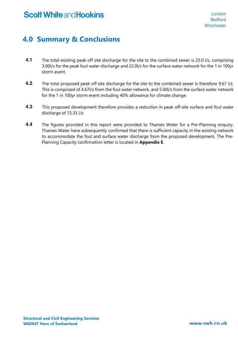
London Bedford
Winchester
Structural and Civil Engineering Services W02047 Hero of Switzerland
4.0 Summary & Conclusions
4.1 The total existing peak off site discharge for the site to the combined sewer is 25.0 l/s, comprising
3.00l/s for the peak foul water discharge and 22.0l/s for the surface water network for the 1 in 100yr storm event.
4.2 The total proposed peak off site discharge for the site to the combined sewer is therefore 9.67 l/s. This is comprised of 4.67l/s from the foul water network, and 5.00l/s from the surface water network for the 1 in 100yr storm event including 40% allowance for climate change.
4.3 This proposed development therefore provides a reduction in peak off-site surface and foul water discharge of 15.33 l/s.
4.4 The figures provided in this report were provided to Thames Water for a Pre-Planning enquiry. Thames Water have subsequently confirmed that there is sufficient capacity in the existing network to accommodate the foul and surface water discharge from the proposed development. The Pre-Planning Capacity confirmation letter is located in Appendix E.

London Bedford
Winchester
Structural and Civil Engineering Services W02047 Hero of Switzerland
Appendices

London Bedford
Winchester
Structural and Civil Engineering Services W02047 Hero of Switzerland
Appendix A Existing Site Layout
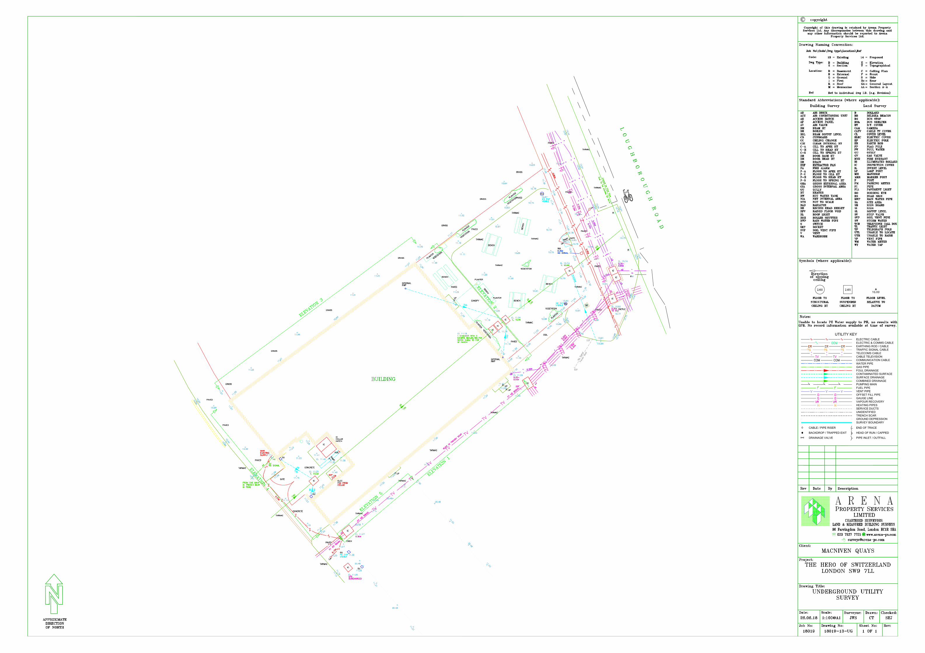
!
UNIDENTIFIED
HEATING PIPESSERVICE DUCTS
VAPOUR RECOVERYGAUGE LINEOFFSET FILL PIPEVENT PIPEFUEL PIPEPUMPING MAINCOMBINED DRAINAGESURFACE DRAINAGECONTAMINATED SURFACEFOUL DRAINAGEGAS PIPEWATER PIPECOMMUNICATION CABLECABLE TELEVISIONTELECOMS CABLE
ELECTRIC CABLE
UTILITY KEY
ELECTRIC & COMMS CABLE
TRAFFIC SIGNAL CABLE
SURVEY BOUNDARY
TRENCH SCARGROUND DEPRESSION
EARTHING ROD / CABLE
END OF TRACECABLE / PIPE RISER
BACKDROP / TRAPPED EXIT HEAD OF RUN / CAPPED
PIPE INLET / OUTFALLDRAINAGE VALVE

London Bedford
Winchester
Structural and Civil Engineering Services W02047 Hero of Switzerland
Appendix B MicroDrainage Existing Surface Water Calculations

Scott-White & Hookins Page 142 West Street W02047London House Hero of SwitzerlandCarshalton SM5 2PR Existing Runoff RatesDate 03/09/2018 16:13 Designed by HHFile W0247 Existing runoff Rates.MDX Checked byMicro Drainage Network 2018.1
STORM SEWER DESIGN by the Modified Rational Method
Design Criteria for Storm
©1982-2018 Innovyze
Pipe Sizes STANDARD Manhole Sizes STANDARD
FSR Rainfall Model - England and WalesReturn Period (years) 100 PIMP (%) 100
M5-60 (mm) 20.100 Add Flow / Climate Change (%) 0Ratio R 0.436 Minimum Backdrop Height (m) 0.200
Maximum Rainfall (mm/hr) 50 Maximum Backdrop Height (m) 1.500Maximum Time of Concentration (mins) 30 Min Design Depth for Optimisation (m) 1.200
Foul Sewage (l/s/ha) 0.000 Min Vel for Auto Design only (m/s) 1.00Volumetric Runoff Coeff. 0.750 Min Slope for Optimisation (1:X) 500
Designed with Level Soffits
Time Area Diagram for Storm
Time(mins)
Area(ha)
Time(mins)
Area(ha)
0-4 0.043 4-8 0.002
Total Area Contributing (ha) = 0.045
Total Pipe Volume (m³) = 0.532
Network Design Table for Storm
PN Length(m)
Fall(m)
Slope(1:X)
I.Area(ha)
T.E.(mins)
BaseFlow (l/s)
k(mm)
HYDSECT
DIA(mm)
Section Type AutoDesign
S1.000 22.772 0.500 45.5 0.023 4.00 0.0 0.600 o 150 Pipe/ConduitS1.001 7.313 0.320 22.9 0.022 0.00 0.0 0.600 o 150 Pipe/Conduit
Network Results Table
PN Rain(mm/hr)
T.C.(mins)
US/IL(m)
Σ I.Area(ha)
Σ BaseFlow (l/s)
Foul(l/s)
Add Flow(l/s)
Vel(m/s)
Cap(l/s)
Flow(l/s)
S1.000 50.00 4.25 10.500 0.023 0.0 0.0 0.0 1.49 26.4 3.1S1.001 50.00 4.31 10.000 0.045 0.0 0.0 0.0 2.12 37.4 6.1

Scott-White & Hookins Page 242 West Street W02047London House Hero of SwitzerlandCarshalton SM5 2PR Existing Runoff RatesDate 03/09/2018 16:13 Designed by HHFile W0247 Existing runoff Rates.MDX Checked byMicro Drainage Network 2018.1
Area Summary for Storm
©1982-2018 Innovyze
PipeNumber
PIMPType
PIMPName
PIMP(%)
GrossArea (ha)
Imp.Area (ha)
Pipe Total(ha)
1.000 - - 100 0.023 0.023 0.0231.001 - - 100 0.022 0.022 0.022
Total Total Total0.045 0.045 0.045
Free Flowing Outfall Details for Storm
OutfallPipe Number
OutfallName
C. Level(m)
I. Level(m)
MinI. Level
(m)
D,L(mm)
W(mm)
S1.001 S 10.740 9.680 7.320 0 0
Simulation Criteria for Storm
Volumetric Runoff Coeff 0.750 Additional Flow - % of Total Flow 0.000Areal Reduction Factor 1.000 MADD Factor * 10m³/ha Storage 2.000
Hot Start (mins) 0 Inlet Coeffiecient 0.800Hot Start Level (mm) 0 Flow per Person per Day (l/per/day) 0.000
Manhole Headloss Coeff (Global) 0.500 Run Time (mins) 60Foul Sewage per hectare (l/s) 0.000 Output Interval (mins) 1
Number of Input Hydrographs 0 Number of Offline Controls 0 Number of Time/Area Diagrams 0Number of Online Controls 0 Number of Storage Structures 0 Number of Real Time Controls 0
Synthetic Rainfall Details
Rainfall Model FSR Profile Type SummerReturn Period (years) 100 Cv (Summer) 0.750
Region England and Wales Cv (Winter) 0.840M5-60 (mm) 20.100 Storm Duration (mins) 30
Ratio R 0.436

Scott-White & Hookins Page 342 West Street W02047London House Hero of SwitzerlandCarshalton SM5 2PR Existing Runoff RatesDate 03/09/2018 16:13 Designed by HHFile W0247 Existing runoff Rates.MDX Checked byMicro Drainage Network 2018.1
1 year Return Period Summary of Critical Results by Maximum Outflow (Rank 1) for Storm
©1982-2018 Innovyze
Simulation CriteriaAreal Reduction Factor 1.000 Additional Flow - % of Total Flow 0.000
Hot Start (mins) 0 MADD Factor * 10m³/ha Storage 2.000Hot Start Level (mm) 0 Inlet Coeffiecient 0.800
Manhole Headloss Coeff (Global) 0.500 Flow per Person per Day (l/per/day) 0.000Foul Sewage per hectare (l/s) 0.000
Number of Input Hydrographs 0 Number of Offline Controls 0 Number of Time/Area Diagrams 0Number of Online Controls 0 Number of Storage Structures 0 Number of Real Time Controls 0
Synthetic Rainfall DetailsRainfall Model FSR M5-60 (mm) 20.000 Cv (Summer) 0.750
Region England and Wales Ratio R 0.432 Cv (Winter) 0.840
Margin for Flood Risk Warning (mm) 300.0 DVD Status OFFAnalysis Timestep Fine Inertia Status OFF
DTS Status ON
Profile(s) Summer and WinterDuration(s) (mins) 15, 30, 60, 120, 180, 240, 360, 480, 600, 720, 960,
1440Return Period(s) (years) 1, 30, 100
Climate Change (%) 0, 0, 0
PNUS/MHName Storm
ReturnPeriod
ClimateChange
First (X)Surcharge
First (Y)Flood
First (Z)Overflow
OverflowAct.
Water Level(m)
SurchargedDepth(m)
FloodedVolume(m³)
S1.000 S1 15 Winter 1 +0% 10.537 -0.113 0.000S1.001 S2 15 Winter 1 +0% 10.045 -0.105 0.000
PNUS/MHName
Flow /Cap.
Overflow(l/s)
PipeFlow(l/s) Status
LevelExceeded
S1.000 S1 0.14 3.5 OKS1.001 S2 0.19 6.2 OK

Scott-White & Hookins Page 442 West Street W02047London House Hero of SwitzerlandCarshalton SM5 2PR Existing Runoff RatesDate 03/09/2018 16:13 Designed by HHFile W0247 Existing runoff Rates.MDX Checked byMicro Drainage Network 2018.1
30 year Return Period Summary of Critical Results by Maximum Outflow (Rank 1) for Storm
©1982-2018 Innovyze
Simulation CriteriaAreal Reduction Factor 1.000 Additional Flow - % of Total Flow 0.000
Hot Start (mins) 0 MADD Factor * 10m³/ha Storage 2.000Hot Start Level (mm) 0 Inlet Coeffiecient 0.800
Manhole Headloss Coeff (Global) 0.500 Flow per Person per Day (l/per/day) 0.000Foul Sewage per hectare (l/s) 0.000
Number of Input Hydrographs 0 Number of Offline Controls 0 Number of Time/Area Diagrams 0Number of Online Controls 0 Number of Storage Structures 0 Number of Real Time Controls 0
Synthetic Rainfall DetailsRainfall Model FSR M5-60 (mm) 20.000 Cv (Summer) 0.750
Region England and Wales Ratio R 0.432 Cv (Winter) 0.840
Margin for Flood Risk Warning (mm) 300.0 DVD Status OFFAnalysis Timestep Fine Inertia Status OFF
DTS Status ON
Profile(s) Summer and WinterDuration(s) (mins) 15, 30, 60, 120, 180, 240, 360, 480, 600, 720, 960,
1440Return Period(s) (years) 1, 30, 100
Climate Change (%) 0, 0, 0
PNUS/MHName Storm
ReturnPeriod
ClimateChange
First (X)Surcharge
First (Y)Flood
First (Z)Overflow
OverflowAct.
Water Level(m)
SurchargedDepth(m)
FloodedVolume(m³)
S1.000 S1 15 Summer 30 +0% 10.561 -0.089 0.000S1.001 S2 15 Winter 30 +0% 10.077 -0.073 0.000
PNUS/MHName
Flow /Cap.
Overflow(l/s)
PipeFlow(l/s) Status
LevelExceeded
S1.000 S1 0.35 8.6 OKS1.001 S2 0.53 16.9 OK
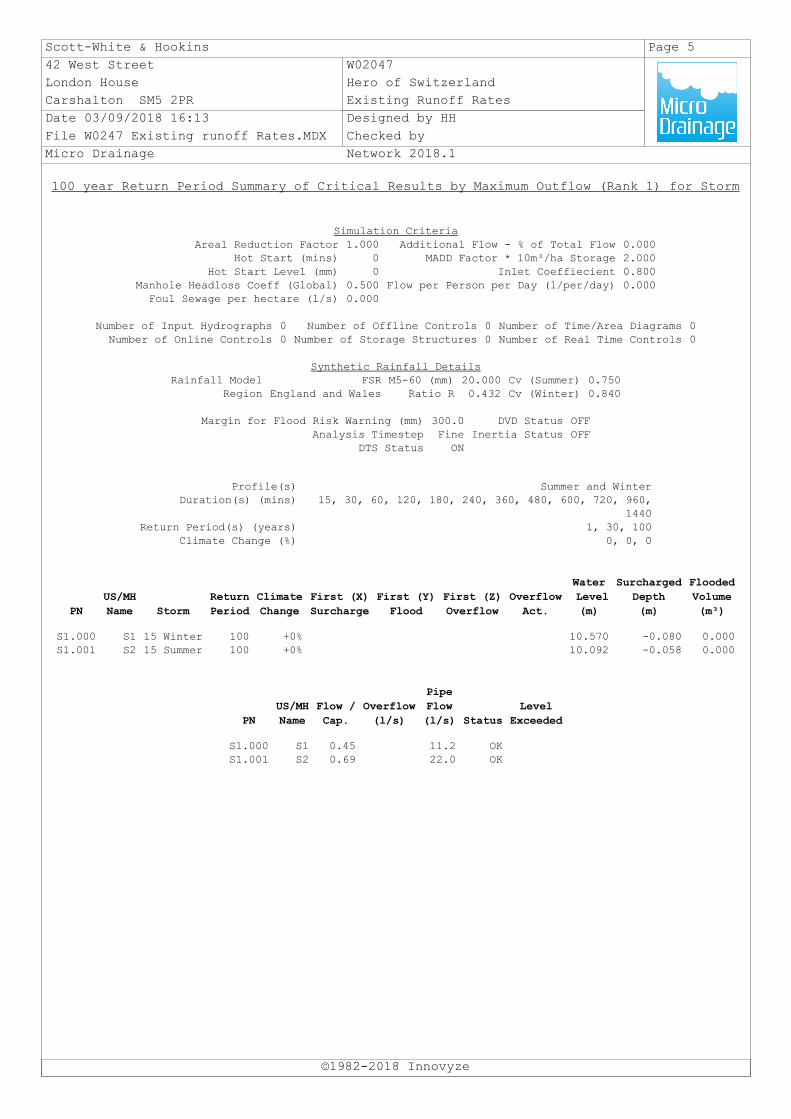
Scott-White & Hookins Page 542 West Street W02047London House Hero of SwitzerlandCarshalton SM5 2PR Existing Runoff RatesDate 03/09/2018 16:13 Designed by HHFile W0247 Existing runoff Rates.MDX Checked byMicro Drainage Network 2018.1
100 year Return Period Summary of Critical Results by Maximum Outflow (Rank 1) for Storm
©1982-2018 Innovyze
Simulation CriteriaAreal Reduction Factor 1.000 Additional Flow - % of Total Flow 0.000
Hot Start (mins) 0 MADD Factor * 10m³/ha Storage 2.000Hot Start Level (mm) 0 Inlet Coeffiecient 0.800
Manhole Headloss Coeff (Global) 0.500 Flow per Person per Day (l/per/day) 0.000Foul Sewage per hectare (l/s) 0.000
Number of Input Hydrographs 0 Number of Offline Controls 0 Number of Time/Area Diagrams 0Number of Online Controls 0 Number of Storage Structures 0 Number of Real Time Controls 0
Synthetic Rainfall DetailsRainfall Model FSR M5-60 (mm) 20.000 Cv (Summer) 0.750
Region England and Wales Ratio R 0.432 Cv (Winter) 0.840
Margin for Flood Risk Warning (mm) 300.0 DVD Status OFFAnalysis Timestep Fine Inertia Status OFF
DTS Status ON
Profile(s) Summer and WinterDuration(s) (mins) 15, 30, 60, 120, 180, 240, 360, 480, 600, 720, 960,
1440Return Period(s) (years) 1, 30, 100
Climate Change (%) 0, 0, 0
PNUS/MHName Storm
ReturnPeriod
ClimateChange
First (X)Surcharge
First (Y)Flood
First (Z)Overflow
OverflowAct.
Water Level(m)
SurchargedDepth(m)
FloodedVolume(m³)
S1.000 S1 15 Winter 100 +0% 10.570 -0.080 0.000S1.001 S2 15 Summer 100 +0% 10.092 -0.058 0.000
PNUS/MHName
Flow /Cap.
Overflow(l/s)
PipeFlow(l/s) Status
LevelExceeded
S1.000 S1 0.45 11.2 OKS1.001 S2 0.69 22.0 OK

London Bedford
Winchester
Structural and Civil Engineering Services W02047 Hero of Switzerland
Appendix C Proposed Site Layout
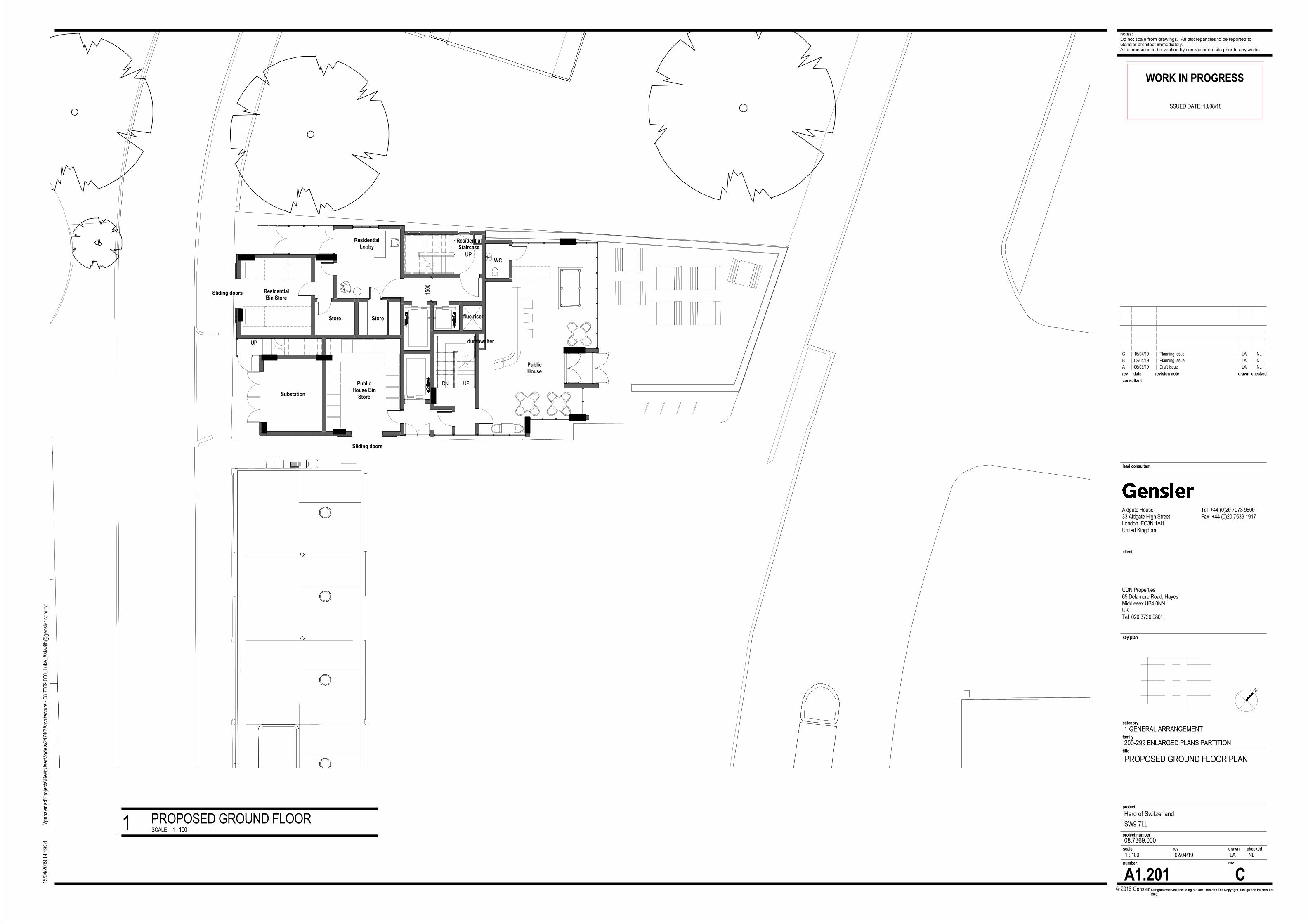
UP
UP
UPDN
ResidentialStaircase
flue riser
PublicHouse
dumbwaiter
1500
StoreStore
ResidentialBin Store
ResidentialLobby
Sliding doors
WC
Sliding doors
PublicHouse Bin
StoreSubstation
WORK IN PROGRESS
date revision note drawn checkedrev
N
© Gensler All rights reserved, including but not limited to The Copyright, Design and Patents Act 1988
key plan
category
project
client
2016
number rev
rev drawn checkedscale
family
project number
notes:Do not scale from drawings. All discrepancies to be reported to Gensler architect immediately.All dimensions to be verified by contractor on site prior to any works
lead consultant
consultant
title
ISSUED DATE: 13/08/18
Tel +44 (0)20 7073 9600Fax +44 (0)20 7539 1917
Aldgate House33 Aldgate High StreetLondon, EC3N 1AHUnited Kingdom
UDN Properties65 Delamere Road, HayesMiddlesex UB4 0NNUKTel 020 3726 9801
1 : 100
15/0
4/20
19 1
4:19
:31
\\gen
sler .a
d\Pr
ojects
\Rev
itUse
rMod
els\2
4746
\Arc
hitec
ture
- 08
. 736
9.00
0_Lu
ke_A
skwi
th@
gens
ler.c o
m.rv
t
CA1.201
PROPOSED GROUND FLOOR PLAN
08.7369.000
Hero of SwitzerlandSW9 7LL
1 GENERAL ARRANGEMENT
200-299 ENLARGED PLANS PARTITION
02/04/19 NLLA
A 06/03/19 Draft Issue LA NLB 02/04/19 Planning Issue LA NLC 15/04/19 Planning Issue LA NL
SCALE: 1 : 100PROPOSED GROUND FLOOR1

London Bedford
Winchester
Structural and Civil Engineering Services W02047 Hero of Switzerland
Appendix D MicroDrainage Proposed Surface Water Calculations

Scott-White & Hookins Page 142 West Street W02047London House Hero of SwitzerlandCarshalton SM5 2PR Attenuation CalcsDate 03/09/2018 17:45 Designed by HHFile W02047 Attenuation Calcs.SRCX Checked byMicro Drainage Source Control 2018.1
Summary of Results for 100 year Return Period (+40%)
©1982-2018 Innovyze
Half Drain Time : 20 minutes.
StormEvent
MaxLevel(m)
MaxDepth(m)
MaxInfiltration
(l/s)
MaxControl(l/s)
MaxΣ Outflow(l/s)
MaxVolume(m³)
Status
15 min Summer 10.297 0.297 0.0 5.0 5.0 9.0 O K30 min Summer 10.336 0.336 0.0 5.0 5.0 10.2 O K60 min Summer 10.331 0.331 0.0 5.0 5.0 10.1 O K120 min Summer 10.266 0.266 0.0 5.0 5.0 8.1 O K180 min Summer 10.203 0.203 0.0 5.0 5.0 6.2 O K240 min Summer 10.157 0.157 0.0 5.0 5.0 4.8 O K360 min Summer 10.114 0.114 0.0 4.6 4.6 3.5 O K480 min Summer 10.097 0.097 0.0 3.8 3.8 2.9 O K600 min Summer 10.086 0.086 0.0 3.3 3.3 2.6 O K720 min Summer 10.079 0.079 0.0 2.8 2.8 2.4 O K960 min Summer 10.069 0.069 0.0 2.3 2.3 2.1 O K1440 min Summer 10.057 0.057 0.0 1.7 1.7 1.7 O K2160 min Summer 10.048 0.048 0.0 1.2 1.2 1.4 O K2880 min Summer 10.042 0.042 0.0 1.0 1.0 1.3 O K4320 min Summer 10.035 0.035 0.0 0.7 0.7 1.1 O K5760 min Summer 10.031 0.031 0.0 0.5 0.5 0.9 O K7200 min Summer 10.028 0.028 0.0 0.5 0.5 0.9 O K8640 min Summer 10.026 0.026 0.0 0.4 0.4 0.8 O K10080 min Summer 10.024 0.024 0.0 0.3 0.3 0.7 O K
15 min Winter 10.340 0.340 0.0 5.0 5.0 10.3 O K30 min Winter 10.380 0.380 0.0 5.0 5.0 11.5 O K60 min Winter 10.364 0.364 0.0 5.0 5.0 11.1 O K120 min Winter 10.261 0.261 0.0 5.0 5.0 7.9 O K180 min Winter 10.170 0.170 0.0 5.0 5.0 5.2 O K
StormEvent
Rain(mm/hr)
FloodedVolume(m³)
DischargeVolume(m³)
Time-Peak(mins)
15 min Summer 141.917 0.0 12.0 1530 min Summer 91.958 0.0 15.5 2560 min Summer 56.713 0.0 19.1 42120 min Summer 33.812 0.0 22.8 74180 min Summer 24.675 0.0 25.0 104240 min Summer 19.628 0.0 26.5 134360 min Summer 14.150 0.0 28.6 188480 min Summer 11.224 0.0 30.3 248600 min Summer 9.372 0.0 31.6 308720 min Summer 8.084 0.0 32.7 370960 min Summer 6.399 0.0 34.5 4901440 min Summer 4.596 0.0 37.2 7342160 min Summer 3.296 0.0 40.0 11002880 min Summer 2.602 0.0 42.1 14684320 min Summer 1.862 0.0 45.2 21885760 min Summer 1.467 0.0 47.5 28647200 min Summer 1.219 0.0 49.3 36488640 min Summer 1.047 0.0 50.9 440010080 min Summer 0.921 0.0 52.2 5024
15 min Winter 141.917 0.0 13.4 1630 min Winter 91.958 0.0 17.4 2660 min Winter 56.713 0.0 21.4 46120 min Winter 33.812 0.0 25.5 80180 min Winter 24.675 0.0 28.0 108

Scott-White & Hookins Page 242 West Street W02047London House Hero of SwitzerlandCarshalton SM5 2PR Attenuation CalcsDate 03/09/2018 17:45 Designed by HHFile W02047 Attenuation Calcs.SRCX Checked byMicro Drainage Source Control 2018.1
Summary of Results for 100 year Return Period (+40%)
©1982-2018 Innovyze
StormEvent
MaxLevel(m)
MaxDepth(m)
MaxInfiltration
(l/s)
MaxControl(l/s)
MaxΣ Outflow(l/s)
MaxVolume(m³)
Status
240 min Winter 10.121 0.121 0.0 4.8 4.8 3.7 O K360 min Winter 10.094 0.094 0.0 3.7 3.7 2.8 O K480 min Winter 10.080 0.080 0.0 2.9 2.9 2.4 O K600 min Winter 10.072 0.072 0.0 2.5 2.5 2.2 O K720 min Winter 10.066 0.066 0.0 2.1 2.1 2.0 O K960 min Winter 10.057 0.057 0.0 1.7 1.7 1.7 O K1440 min Winter 10.048 0.048 0.0 1.2 1.2 1.4 O K2160 min Winter 10.040 0.040 0.0 0.9 0.9 1.2 O K2880 min Winter 10.035 0.035 0.0 0.7 0.7 1.1 O K4320 min Winter 10.030 0.030 0.0 0.5 0.5 0.9 O K5760 min Winter 10.026 0.026 0.0 0.4 0.4 0.8 O K7200 min Winter 10.024 0.024 0.0 0.3 0.3 0.7 O K8640 min Winter 10.022 0.022 0.0 0.3 0.3 0.7 O K10080 min Winter 10.021 0.021 0.0 0.3 0.3 0.6 O K
StormEvent
Rain(mm/hr)
FloodedVolume(m³)
DischargeVolume(m³)
Time-Peak(mins)
240 min Winter 19.628 0.0 29.7 132360 min Winter 14.150 0.0 32.1 190480 min Winter 11.224 0.0 33.9 250600 min Winter 9.372 0.0 35.4 310720 min Winter 8.084 0.0 36.7 370960 min Winter 6.399 0.0 38.7 4921440 min Winter 4.596 0.0 41.7 7342160 min Winter 3.296 0.0 44.8 11002880 min Winter 2.602 0.0 47.2 14324320 min Winter 1.862 0.0 50.7 22005760 min Winter 1.467 0.0 53.2 29047200 min Winter 1.219 0.0 55.3 35768640 min Winter 1.047 0.0 57.0 440010080 min Winter 0.921 0.0 58.5 5072

Scott-White & Hookins Page 342 West Street W02047London House Hero of SwitzerlandCarshalton SM5 2PR Attenuation CalcsDate 03/09/2018 17:45 Designed by HHFile W02047 Attenuation Calcs.SRCX Checked byMicro Drainage Source Control 2018.1
Rainfall Details
©1982-2018 Innovyze
Rainfall Model FSR Winter Storms YesReturn Period (years) 100 Cv (Summer) 0.750
Region England and Wales Cv (Winter) 0.840M5-60 (mm) 20.000 Shortest Storm (mins) 15
Ratio R 0.432 Longest Storm (mins) 10080Summer Storms Yes Climate Change % +40
Time Area Diagram
Total Area (ha) 0.045
TimeFrom:
(mins)To:
Area(ha)
0 4 0.045

Scott-White & Hookins Page 442 West Street W02047London House Hero of SwitzerlandCarshalton SM5 2PR Attenuation CalcsDate 03/09/2018 17:45 Designed by HHFile W02047 Attenuation Calcs.SRCX Checked byMicro Drainage Source Control 2018.1
Model Details
©1982-2018 Innovyze
Storage is Online Cover Level (m) 11.200
Cellular Storage Structure
Invert Level (m) 10.000 Safety Factor 2.0Infiltration Coefficient Base (m/hr) 0.00000 Porosity 0.95Infiltration Coefficient Side (m/hr) 0.00000
Depth (m) Area (m²) Inf. Area (m²) Depth (m) Area (m²) Inf. Area (m²) Depth (m) Area (m²) Inf. Area (m²)
0.000 32.0 32.0 0.400 32.0 41.1 0.401 0.0 41.1
Hydro-Brake® Optimum Outflow Control
Unit Reference MD-SHE-0114-5000-0400-5000Design Head (m) 0.400
Design Flow (l/s) 5.0Flush-Flo™ CalculatedObjective Minimise upstream storage
Application SurfaceSump Available YesDiameter (mm) 114
Invert Level (m) 10.000Minimum Outlet Pipe Diameter (mm) 150Suggested Manhole Diameter (mm) 1200
Control Points Head (m) Flow (l/s) Control Points Head (m) Flow (l/s)
Design Point (Calculated) 0.400 5.0 Kick-Flo® 0.312 4.5Flush-Flo™ 0.169 5.0 Mean Flow over Head Range - 4.0
The hydrological calculations have been based on the Head/Discharge relationship for the Hydro-Brake®Optimum as specified. Should another type of control device other than a Hydro-Brake Optimum® beutilised then these storage routing calculations will be invalidated
Depth (m) Flow (l/s) Depth (m) Flow (l/s) Depth (m) Flow (l/s) Depth (m) Flow (l/s) Depth (m) Flow (l/s)
0.100 4.0 0.800 6.9 2.000 10.6 4.000 14.8 7.000 19.50.200 5.0 1.000 7.7 2.200 11.1 4.500 15.6 7.500 20.20.300 4.6 1.200 8.3 2.400 11.6 5.000 16.4 8.000 20.90.400 5.0 1.400 9.0 2.600 12.0 5.500 17.3 8.500 21.50.500 5.5 1.600 9.6 3.000 12.9 6.000 18.0 9.000 22.10.600 6.0 1.800 10.1 3.500 13.9 6.500 18.8 9.500 22.7

London Bedford
Winchester
Structural and Civil Engineering Services W02047 Hero of Switzerland
Appendix E Thames Water Capacity Confirmation Letter

Thames Water Utilities Limited – Registered Office: Clearwater Court, Vastern Road, Reading RG1 8DB Company number 02366661. VAT registration no GB 537-4569-15
Mr. Harry Hunter Scott White and Hookins LLP Harman House Andover Road SO23 7BS
DS6052898
30 October 2018
Pre-planning enquiry: Confirmation of sufficient capacity
Dear Mr. Hunter,
Thank you for providing information on your development at Hero of Switzerland, 142 Longhborough Road, Stockwell, London, SW9 7LL. Existing site is 300sqm of public house, foul discharge via gravity, existing SW rates 1 in 1: 6.2l/s, 1 in 30 16.9l/s, 1 in 100: 22l/s via existing chamber which discharges into 1140x760 combined sewer. Development proposal for retaining existing public house and proposed 36 flats, foul discharge by gravity, proposed SW rates at 5l/s via existing chamber which discharges into 1140x760 combined sewer.
We have completed the assessment of the foul water flows and surface water run-off based on the information submitted in your application with the purpose of assessing sewerage capacity within the existing Thames Water sewer network.
Foul Water
If your proposals progress in line with the details you’ve provided, we’re pleased to confirm that there will be sufficient sewerage capacity in the adjacent combined sewer network to serve your development. This confirmation is valid for 12 months or for the life of any planning approval that this information is used to support, to a maximum of three years.
You’ll need to keep us informed of any changes to your design – for example, an increase in the number or density of homes. Such changes could mean there is no longer sufficient capacity.
Surface Water
We confirm that there will be sufficient capacity in our sewerage network to accept the surface water discharge rate provided as part of the enquiry, however this does not preclude the requirement as set out by the Policy 5.13 of the London Plan.
Management of surface water from the site should follow policy 5.13 of the London Plan, development should ‘aim to achieve greenfield run-off rates’ utilising Sustainable Drainage and where this is not possible information explaining why it is not possible should be provided to both the LLFA and Thames Water.

Typically greenfield run off rates of 5l/s/ha should be aimed for using the drainage hierarchy. The hierarchy lists the preference for surface water disposal as follows; Store Rainwater for later use > Use infiltration techniques, such as porous surfaces in non-clay areas > Attenuate rainwater in ponds or open water features for gradual release > Discharge rainwater direct to a watercourse > Discharge rainwater direct to a surface water sewer/drain > Discharge rainwater to the combined sewer.
No green/blue roof proposed so could possibly restrict further.
What happens next? Please make sure you submit your connection application, giving us at least 21 days’ notice of the date you wish to make your new connection/s. If you’ve any further questions, please contact me on 0203 577 9018 / 07747 640 273.
Yours sincerely
David Stamateris
Adoptions Engineer
Thames Water