
171025 AMA Design Recommendations Pneumatic Structures K ... · Pneumatic structures are classified...
22
Design Recommendations Designing Air inflated Structures Air Supply Systems for ETFE-Foil Cushions state: 2017-10-25 copyright: Karsten Moritz contact: [email protected] published: www.amaforum.com AMA design recommendations have been created for the orientation and support of interested readers. The shown information is developed and compiled to the author’s best knowledge and belief. Despite careful processing and correction, liability for the content cannot be accepted neither by the author nor by the Architectural Membrane Association e.V. (AMA). Please contact the author for mistakes you may have found. Table of content 1.0 Purpose ...................................................................................................................................................... 2 2.0 Typology ..................................................................................................................................................... 2 3.0 Air inflated cushions.................................................................................................................................... 3 3.1. Principle shapes ..................................................................................................................................... 3 3.2. Load bearing behavior............................................................................................................................ 4 3.3. Assembly situations................................................................................................................................ 6 3.4. Parameters (nomenclature) .................................................................................................................... 9 3.5. Dimensions .......................................................................................................................................... 11 3.6. Number of layers .................................................................................................................................. 12 3.7. Curvature of middle layers ................................................................................................................... 13 3.8. Separation of layers ............................................................................................................................. 14 4.0 Air supply systems .................................................................................................................................... 15 4.1. Stationary systems, open systems and circuit systems........................................................................ 15 4.2. Air intake .............................................................................................................................................. 17 4.3. Airflow Principles (Air Management) .................................................................................................... 18 5.0 Pneumatic Shading Systems .................................................................................................................... 21 6.0 Sources .................................................................................................................................................... 22
Transcript of 171025 AMA Design Recommendations Pneumatic Structures K ... · Pneumatic structures are classified...

Design Recommendations
Designing Air inflated Structures
Air Supply Systems for ETFE-Foil Cushions
state: 2017-10-25
copyright: Karsten Moritz
contact: [email protected]
published: www.amaforum.com
AMA design recommendations have been created for the orientation and support of interested readers. The shown information is developed and compiled to the author ’s best knowledge and belief. Despite careful processing and correction, liability for the content cannot be accepted neither by the author nor by the Architectural Membrane Association e.V. (AMA). Please contact the author for mistakes you may have found.
Table of content
1.0 Purpose ...................................................................................................................................................... 2
2.0 Typology ..................................................................................................................................................... 2
3.0 Air inflated cushions.................................................................................................................................... 3
3.1. Principle shapes ..................................................................................................................................... 3
3.2. Load bearing behavior ............................................................................................................................ 4
3.3. Assembly situations ................................................................................................................................ 6
3.4. Parameters (nomenclature) .................................................................................................................... 9
3.5. Dimensions .......................................................................................................................................... 11
3.6. Number of layers .................................................................................................................................. 12
3.7. Curvature of middle layers ................................................................................................................... 13
3.8. Separation of layers ............................................................................................................................. 14
4.0 Air supply systems .................................................................................................................................... 15
4.1. Stationary systems, open systems and circuit systems ........................................................................ 15
4.2. Air intake .............................................................................................................................................. 17
4.3. Airflow Principles (Air Management) .................................................................................................... 18
5.0 Pneumatic Shading Systems .................................................................................................................... 21
6.0 Sources .................................................................................................................................................... 22

2 / 22
1.0 Purpose
These design recommendations refer to aspects of the constructional design of pneumatic structures, especially air inflated (pneumatically supported) cushions. Currently, this construction method is made of ETFE-foils preferably. The document focus on the principles of the load bearing behavior of ETFE-foil cushions and on the air supply system, which is necessary for the inflation with air, for flushing of the enclosed chambers and for stabilization of the different layers.
Meanwhile, certain construction methods have proven to be favorable or unfavorable. The documentshows the various design principles and options with short explanations of the advantages anddisadvantages.
2.0 Typology
Pneumatic structures are classified by the following principal types (Fig. 1).
Fig. 1 Typology of pneumatic structures [1] initially based on [5]

3 / 22
Usually air domes, cushion systems and vacuum systems are characterized by a quite low pressure difference up to approximately 600 Pa, sometimes a bit more, to the environmental atmospheric pressures pe (e = external) and pi (i = internal). Conversely, tube systems usually have a much biggerpressure difference of more than 1 bar (100,000 Pa) to the atmospheric pressure, to ensure appropriate deflections, also in cases of external design loads induced by wind and snow.
3.0 Air inflated cushions
3.1. Principle shapes
Shape planar boundary spacial boundary
circular
polygonal
square
rectangular
rhombic
trianglular
Fig. 2 Pneumatic structures – air inflated cushions – principle shapes / surfaces [2]

4 / 22
3.2. Load bearing behavior
Using the boiler formula the principal forces in a layer of a square shaped cushion (Fig. 3) in a biaxial stress state (inner pressure) can be evaluated roughly as follows.
uniaxial load transfer: ∙
biaxial load transfer:
The equations don’t consider either transversal contraction of the material nor the deformation of theinitial geometry.
Fig. 3 Principal forces in the outer layer of a square cushion exposed by inner pressure [3]
Fig. 4 Principle of the uniaxial load bearing behavior of a pneumatic cushion (3-layer system) - load case pre-stress (internal pressures p1 and p2) [1]
© K. M oritz
© L. Schiemann
pi
pe
© K. Moritz actio: | FH| = FH1 + FH2 + FH3 = reactio |FH| actio: | FV| = FV1 + FV2 - FV3 = reactio |FV| = 0

5 / 22
Fig. 5 Principle of the uniaxial load bearing behavior of a pneumatic cushion (3-layer system) - load case wind suction Ws [1]
Fig. 6 Principle of the uniaxial load bearing behavior of a pneumatic cushion (3-layer system) - load case uniform snow S [1]
© K. M oritz
© K. M oritz
pi
pi
© K. Moritz
© K. Moritz
actio: | FH| = FH1 + FH2 + FH3 = reactio |FH| actio: | FV| = FV1 + FV2 - FV3 = reactio |FV| = Ws,v * l * 0.5
actio: | FH| = FH1 + FH2 + FH3 = reactio |FH| actio: | FV| = FV1 + FV2 - FV3 = reactio |FV| = S * l * 0.5

6 / 22
Fig. 7 Principle of the uniaxial load bearing behavior of a pneumatic cushion (3-layer system) - load case uniform snow S on a deflated cushion or if the snow load S exceeds the internal pressure in the cushion [1]
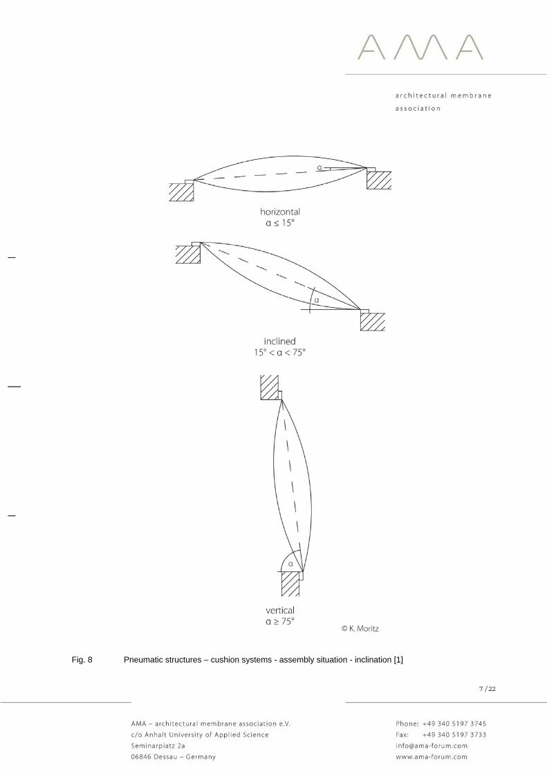
3.3. Assembly situations
Air inflated cushions can be used, for example, as roof, façade or as complete building envelope. Thedistinction of the three ranges of inclination (horizontal, inclined and vertical) has been chosen, becauseof the following important reasons (Fig. 8):
- The applicability of the Eurocode EN 13830: 2015 - Curtain walling - Product standard refers to ”vertical” façades (curtain walls) with an inclination of 75° and more [4].
- Especially cushions with an inclination lower than 15° (“horizontal” cushions”) are endangered due to the risk of water ponds. For usual cushion geometries with inclinations of 15° and more,the water normally can drain above the eave. Nevertheless, the investigation of the water pond risk should be done also for such structures.
FH
FV pi
pe
© K. Moritz
actio: | FH| = FH1 + FH2 + FH3 = reactio |FH| actio: | FV| = FV1 + FV2 + FV3 = reactio |FV| = S * l * 0.5
7 / 22
Fig. 8 Pneumatic structures – cushion systems - assembly situation - inclination [1]

8 / 22
Fig. 9 Pneumatic structures – cushion systems - assembly situation - openness of buildings [1]
Membranes, also ETFE-foils, are sensitive to changes in temperature. The temperature can influencethe material stiffness, the deformations and the design limits of plastic materials significantly (tensile strength, yield stress etc.). Each layer can achieve a different temperature in the same load case. For example, the temperature of the inner (lower) layer has a different temperature and material resistance(to wind pressure) as the outer (upper) layer (to wind suction). Therefore, the question, if the building is open or closed is of importance for the temperature approach for the specific layer and finally for thereliability of the structural analyses, which are done layer by layer.

9 / 22
3.4. Parameters (nomenclature)
Fig. 10 Pneumatic structures – cushion systems – parameters (nomenclature): pressures p / pressure differences p, chambers c, layers l, aerodynamic sections as [1]
The unification of parameters, units and indicees according to the Eurocode and to the sysetem of SI-units is imporatant, to avoid missunderstandings. Air supported cushions can be described by the following parameters and acronyms:
- pressure p, pressure difference p [Pa] - chambers c, layers l [-] - aerodynamic sections (valves) [mm²]
- temperatures T [°C], temperature difference T [K] - volumes V [m³] - airflow velocities v [m/s] - air exchange rate AER [1/d] - airflow rate [m³/h]

10 / 22
Fig. 11 Pneumatic structures – cushion systems – parameters (nomenclature): temperatures T / temperature differences T, volumes V and airflow velocities v [1]
Air inflated cushions need an air supply for their stabilization, for wrinkle-free surfaces, for the curvature of the different layers (pressure differences) and sometimes for a pneumatic shading system, by using one or more moveable middle layers. Usually, the air supply is provided by an air blower unit (ABU) and an air duct system. The blower unit delivers an overpressure related to the atmospheric pressure around, which leads to overpressures of approximately 600 Pa, sometimes a bit more, inside the cushions.

11 / 22
3.5. Dimensions
The following dimensions decribe the geometrie of air inflated cushions entirely:
length l [m], span width s [m], radius r [m], arc length b [m] and sag f [m] (Figure 11).
Fig. 12 Pneumatic structures – cushion systems –dimensions [1]

12 / 22
3.6. Number of layers
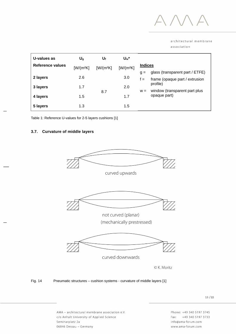
The thermal insulation of an air supported ETFE-foil cushion system improves with the number of layers. Rough reference values can be given, based on calculations done according to the respectiveEurocodes. However, the UW-value depends on some parameters, like the thermal insulation of the clamping profile and the ratio of profiles (opaque part) and cushions (transparent part).
Fig. 13 Pneumatic structures – cushion systems – number of layers (2-5 layers systems) [1]
13 / 22
U-values as
Reference values
Ug Uf Uw*
Indices
g = glass (transparent part / ETFE)
f = frame (opaque part / extrusion profile)
w = window (transparent part plus opaque part)
[W/(m²K] [W/(m²K] [W/(m²K]
2 layers 2.6
8.7
3.0
3 layers 1.7 2.0
4 layers 1.5 1.7
5 layers 1.3 1.5
Table 1: Reference U-values for 2-5 layers cushions [1]
3.7. Curvature of middle layers
Fig. 14 Pneumatic structures – cushion systems - curvature of middle layers [1]
14 / 22
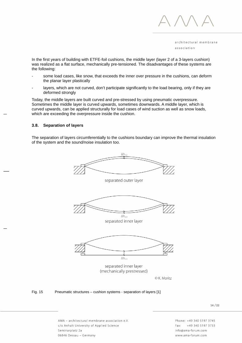
In the first years of building with ETFE-foil cushions, the middle layer (layer 2 of a 3-layers cushion) was realized as a flat surface, mechanically pre-tensioned. The disadvantages of these systems are the following:
- some load cases, like snow, that exceeds the inner over pressure in the cushions, can deform the planar layer plastically
- layers, which are not curved, don’t participate significantly to the load bearing, only if they are deformed strongly
Today, the middle layers are built curved and pre-stressed by using pneumatic overpressure. Sometimes the middle layer is curved upwards, sometimes downwards. A middle layer, which is curved upwards, can be applied structurally for load cases of wind suction as well as snow loads, which are exceeding the overpressure inside the cushion.
3.8. Separation of layers
The separation of layers circumferentially to the cushions boundary can improve the thermal insulation of the system and the sound/noise insulation too.
Fig. 15 Pneumatic structures – cushion systems - separation of layers [1]
15 / 22
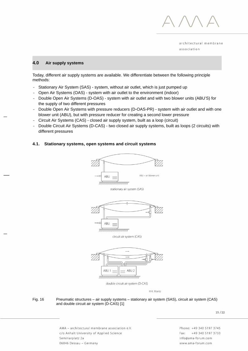
4.0 Air supply systems
Today, different air supply systems are available. We differentiate between the following principle methods:
- Stationary Air System (SAS) - system, without air outlet, which is just pumped up - Open Air Systems (OAS) - system with air outlet to the environment (indoor) - Double Open Air Systems (D-OAS) - system with air outlet and with two blower units (ABU’S) for
the supply of two different pressures - Double Open Air Systems with pressure reducers (D-OAS-PR) - system with air outlet and with one
blower unit (ABU), but with pressure reducer for creating a second lower pressure - Circuit Air Systems (CAS) - closed air supply system, built as a loop (circuit) - Double Circuit Air Systems (D-CAS) - two closed air supply systems, built as loops (2 circuits) with
different pressures
4.1. Stationary systems, open systems and circuit systems
Fig. 16 Pneumatic structures – air supply systems – stationary air system (SAS), circuit air system (CAS) and double circuit air system (D-CAS) [1]

16 / 22
Fig. 17 Pneumatic structures – air supply systems – open air system (OAS), double open air system (D-OAS) and double open air system with pressure reducer (butterfly valve) [1]

17 / 22
4.2. Air intake
Fig. 18 Pneumatic structures – air supply systems – air intake [1]
For the conditions of the inflating air it is very important, where the air blower unit takes the air from - inside (internal) or outside (external). The expected inside and outside climates (air temperature and air humidity) can be found in the relevant codes, like EN 4108 in Europe. From this point of view, the external air intake is to prefer usually, because the water amount [g/m³] of cold air is lower than of warm air with the same relative humidity [rel H in %].

18 / 22
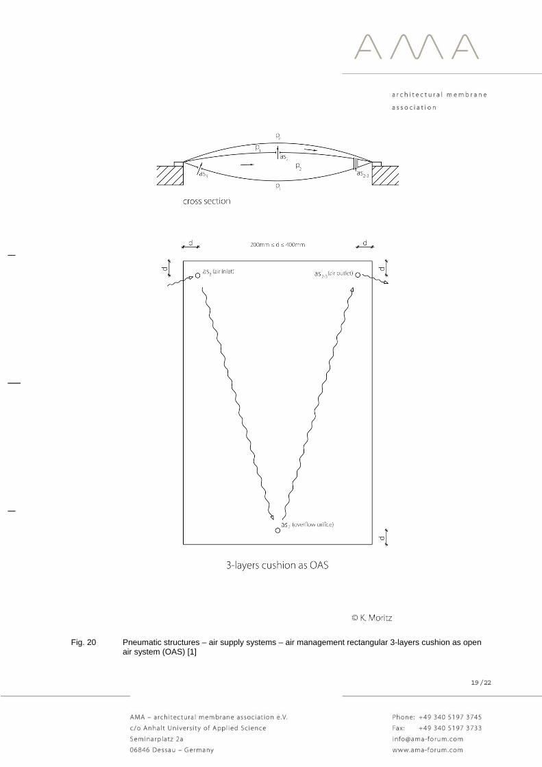
4.3. Airflow Principles (Air Management)
The sufficient air management guarantees a permanent airflow inside the air supported cushions. The airflow is necessary for the avoidance or minimization of condensation inside the cushion and to create a pressure difference at the middle layer. A curved middle layer (for example layer 2 in a 3-layers cushion) cannot be realized without a pressure difference.
Fig. 19 Pneumatic structures – air supply systems – airflow - rectangular 2-layers cushion as open air system (OAS) [1]
19 / 22
Fig. 20 Pneumatic structures – air supply systems – air management rectangular 3-layers cushion as open air system (OAS) [1]

20 / 22
Fig. 21 Pneumatic cushions – air supply systems – air management 4-layers cushion as open air system (OAS) [1]

21 / 22
5.0 Pneumatic Shading Systems
Fig. 22 Pneumatic cushions – air supply systems –types of pneumatic shading systems [1]

22 / 22
6.0 Sources
[1] Moritz, K., Drawings, Germany, 09/2017
[2] Moritz, K., ETFE-foil as Load Bearing Element, Dissertation, TU Munich 2007
[3] Schiemann, L., Load Bearing Behavior of ETFE-Foils in Biaxial Stress States, Dissertation, TU Munich 2009
[4] DIN EN 13830: 2015-07 Curtain walling - Product standard; German version EN 13830: 2015
[5] Herzog, Thomas (author), Minke, Gernot, Eggers, Hans, Pneumatische Konstruktionen - Bauten aus Membranen und Luft, Hatje Cantz Verlag, ISBN-10: 3775700838, ISBN-13: 978-3775700832, 1986
![6 Examples of pneumatic structures and material models for ...Examples of pneumatic structures and material models for membranes. 109. According to Robinson-Gayle et al. [80], ETFE](https://static.fdocuments.in/doc/165x107/5e68e7b104e9ca73e43f6d99/6-examples-of-pneumatic-structures-and-material-models-for-examples-of-pneumatic.jpg)


![Research Article Pneumatic Formwork Systems in … · Pneumatic Formwork Systems in Structural Engineering ... shell form concrete structures [ ]. ... A er in ation of the formwork,](https://static.fdocuments.in/doc/165x107/5b3aac637f8b9a0e628be5b2/research-article-pneumatic-formwork-systems-in-pneumatic-formwork-systems-in.jpg)