170303 AUTOFLEX USA AXLE AND BRAKE MAINTENANCE MANUAL en€¦ · Hubs, Brake Drums, Rotors, and...
20
AXLE AND BRAKE SERVICE & MAINTENANCE MANUAL User Manual www.autoflex-knott.com
Transcript of 170303 AUTOFLEX USA AXLE AND BRAKE MAINTENANCE MANUAL en€¦ · Hubs, Brake Drums, Rotors, and...

AXLE AND BRAKE SERVICE & MAINTENANCE MANUALUser Manual
www.autoflex-knott.com
www.autoflex-knott.com
Table of contents
Introduction 1Quality Policy of Autoflex-Knott Ltd. 1Overview 2Safety 2First steps 2
Hubs, Brake Drums, Rotors, and Bearings 3Removal of hub, brake drum and rotor 3Inspection of the brake drum 3Inspection of the rotor 4Inspection replacement of the seal 4Replacement inspection of the bearing. 5Lubrication - Bearing Grease 6Adjusting the bearing and installing the hub 7
Hydraulic brake System 8Hydraulic brake system 8Hydraulic disc brakes caliper mounting 8
Electric brake systems 9Electric drum brakes 9Mounting of the Electric drum brakes 9Maintenance of the electric drum brakes 10Cleaning and lubricating electric drum brakes 12Electric Drum Brakes – Magnets 12Electric Drum Brakes – Adjustments 13
Leaf Spring Trailer Suspension Systems 14Leaf Type Spring Suspension System– Inspection and Maintenance 14
Torsional Axel Suspension Systems 15How Torsional Axel Suspensions Work 15
Autoflex-Knott Limited Warranty 16

Quality Policy of Autoflex-Knott Ltd.
We define our quality policy—and regularly evaluate our quality—based on our market share, on keeping and satisfying Quality Certificate our customers Autoflex Parts Quality and on providing the best possible services. Our goals are to expand, to sell our products all over the world and to work to our customers' complete satisfaction.
Our company is customer - and market-oriented. Through continuous improvement we are committed to quality products, competitive prices, reduced production costs, on-time deliveries and a high level of customer relationship management while securing a reasonable profit and maintaining our customers satisfaction concerning our products and services.
Quality requires a personal commitment. Every employee of the company, from managers to workers, is expected to perform their job responsible—minded, in strict conformance to quality procedures and with an eye towards continuous quality improvement as far as it lies within their power.
Every employee of the company is required to continuously improve their work, to responsibly watch the quality of their production value and to maintain and look after the company's assets they use.
1
User ManualAXLE AND BRAKE SERVICE & MAINTENANCE MANUAL
www.autoflex-knott.com

www.autoflex-knott.com
Introduction
Tire pressure
Wheel nut torque
Breaks
Overview
Safety
First steps
Thank you for your purchase of an Autoflex – Knott axle. This manual will help you understand its operations, service and maintenance. All the products that are discussed in this manual have been produced to be in line with our customers design, dimensions and strength requirements.
In order to insure the safety and proper operation of your axle as well as the safety of personnel, the service persons carrying out the work should familiarize themselves with this manual and follow it each time they perform service.
Due to all the variables and different levels of experience and skill of those performing the various repair and maintenance tasks it is extremely important that any deviation from the procedures in this manual need to ensure that they are not compromising their safety or the integrity of the vehicle by choosing to use alternate methods, parts, tools or procedures.
Before you operate your trailer and at intervals as indicated herein, the following inspections and adjustments need to be made.
- be sure to check the tire pressure according to the tire manufacturer's requirements
- must be checked at 10, 25, 50 and 250 miles per instructions of this manual.
FSA brakes will continue proper adjustment. Should be periodically inspected visually.Synchronization of breaks - must be performed prior to operation of the trailer per instructions of this manual.
Further additional service and maintenance intervals in addition to that listed above need to be performed as tabulated in the maintenance schedule as required.
1
2
3
2
WARNING!!Prior to attempting any service or perform maintenance on the products included in this manual please consult instructions herein in order to achieve safe and reliable methods of performance.
1
2
34
1
2 3
4 5
1
2
3
41
2
3
4
5
6
567
8
The proper procedure for attachment of your wheels: Wheel Torque values:Wheel Size
12"
13"
14"
15"
16"
st1 Stage
20-25 ft./lbs.
20-25 ft./lbs.
20-25 ft./lbs.
20-25 ft./lbs.
20-25 ft./lbs.
nd2 Stage
35-40 ft./lbs.
35-40 ft./lbs.
50-60 ft./lbs.
50-60 ft./lbs.
50-60 ft./lbs.
rd3 Stage*50-75 ft./lbs.
*50-75 ft./lbs.
*85-95 ft./lbs.
*85-95 ft./lbs.
*85-95 ft./lbs.
*Values shown may have to be adjusted depending on type of wheel used. Please consult the wheel manufacturer for further information.
Hubs, brake drums, rotors, and bearings
1.
2.3.
4. 5.6.
7.
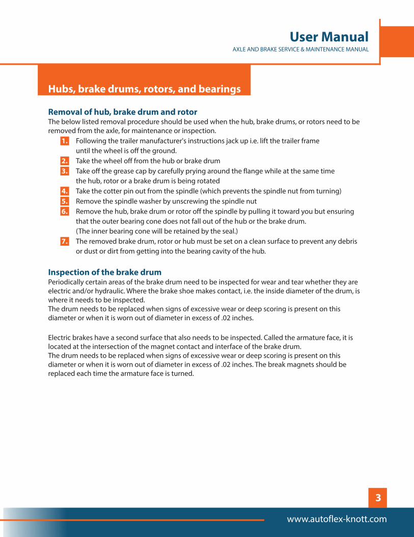
Removal of hub, brake drum and rotor
Inspection of the brake drum
The below listed removal procedure should be used when the hub, brake drums, or rotors need to be removed from the axle, for maintenance or inspection.
Following the trailer manufacturer's instructions jack up i.e. lift the trailer frame until the wheel is off the ground.
Take the wheel off from the hub or brake drum Take off the grease cap by carefully prying around the flange while at the same time
the hub, rotor or a brake drum is being rotatedTake the cotter pin out from the spindle (which prevents the spindle nut from turning)
Remove the spindle washer by unscrewing the spindle nut Remove the hub, brake drum or rotor off the spindle by pulling it toward you but ensuring
that the outer bearing cone does not fall out of the hub or the brake drum. (The inner bearing cone will be retained by the seal.)
The removed brake drum, rotor or hub must be set on a clean surface to prevent any debris or dust or dirt from getting into the bearing cavity of the hub.
Periodically certain areas of the brake drum need to be inspected for wear and tear whether they are electric and/or hydraulic. Where the brake shoe makes contact, i.e. the inside diameter of the drum, is where it needs to be inspected.The drum needs to be replaced when signs of excessive wear or deep scoring is present on this diameter or when it is worn out of diameter in excess of .02 inches.
Electric brakes have a second surface that also needs to be inspected. Called the armature face, it is located at the intersection of the magnet contact and interface of the brake drum.The drum needs to be replaced when signs of excessive wear or deep scoring is present on this diameter or when it is worn out of diameter in excess of .02 inches. The break magnets should be replaced each time the armature face is turned.
3
User ManualAXLE AND BRAKE SERVICE & MAINTENANCE MANUAL
www.autoflex-knott.com

www.autoflex-knott.com
Inspection of the rotor
1
2
The outside places where the brake pads contact the rotor face are to be inspected regularly. If excessive wear or heavy scoring is present replace hub on rotor.
This UHI rotor needs to be replaced if it is worn to such an extent that it cannot be cleaned up to 0.85” Minimum Thickness for an outside diameter of 10 ¼”
Whenever the drum brake is removed from the axle and as indicated in the maintenance schedule, the seal should be inspected. There should be no signs of tear or nicks of the seal lip and its integrity to keeping contamination out of the bearing housing should not be compromised. When the seal needs to be replaced the follow these procedures. With those hubs that are equipped with the conical berings greasing system it is important when changing to seals that only brand name replacements and of the specific part number as shown in the chart is used. Contact an approved/authorised dealer for parts and/or service.
the seal needs to be pried out of the hub. Do not attempt to push the seal through by using the inner bearing as this can cause damage to the inner bearingtap the newly inserted seal back into the hub using a clean flat solid surface such as a block of steel with a larger diameter then the seal.
Inspection replacement of the seal
The seal replacement procedure is as follows
WARNING!!It is important to ensure that the seal be flush or a bit above the top of the hub and especially so if a conical berings greasing system is installed.
4
Replacement inspection of the bearing.
1.2.3.
Whenever the drum brake is removed from the axle and as indicated in the maintenance schedule, the bearing should be inspected. There should be no sign of excessive wear or damage such as broken cages, pitting, corrosion or flat spots on the rollers. Also the bearing cups should be checked for wear or damage (these are the cups pressed into the hub). Should the bearings need to be replaced the procedure in the below chart should be followed. Only use bearings that are suitable for use.
For the bearing cup replacement the following procedure is to be employed. Using a brass punch carefully tap the existing bearing cup out of the hub
Ensure that there are no burrs or nicks by cleaning the bore area after removing the cupInsert the new bearing cup into the hub by carefully tapping and ensure it is seated against the bottom of the bore.
IMPORTANT!iWhen the bearing is replaced it is necessary to also replace the bearing cone.
5
User ManualAXLE AND BRAKE SERVICE & MAINTENANCE MANUAL
www.autoflex-knott.com
Contact AUTOFLEX or the dealer for all service parts.
Lubrication - Bearing Grease
The table below list all approved lubrication for hubs and drums using grease.
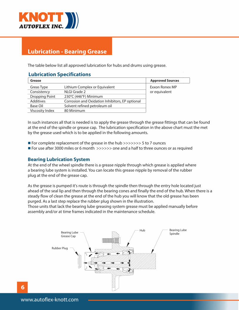
In such instances all that is needed is to apply the grease through the grease fittings that can be found at the end of the spindle or grease cap. The lubrication specification in the above chart must the met by the grease used which is to be applied in the following amounts.
For complete replacement of the grease in the hub >>>>>>> 5 to 7 ounces For use after 3000 miles or 6 month >>>>>> one and a half to three ounces or as required
At the end of the wheel spindle there is a grease nipple through which grease is applied where a bearing lube system is installed. You can locate this grease nipple by removal of the rubber plug at the end of the grease cap.
As the grease is pumped it's route is through the spindle then through the entry hole located just ahead of the seal lip and then through the bearing cones and finally the end of the hub. When there is a steady flow of clean the grease at the end of the hub you will know that the old grease has been purged. As a last step replace the rubber plug shown in the illustration.Those units that lack the bearing lube greasing system grease must be applied manually before assembly and/or at time frames indicated in the maintenance schedule.
n
n
Bearing Lubrication System
www.autoflex-knott.com
Lubrication Specifications
Grease Approved Sources
Greas Type Lithium Complex or EquivalentConsistency NLGI Grade 2 or equivalentDropping Point 230°C (446°F) MinimumAdditives Corrosion and Oxidation Inhibitors, EP optionalBase Oil Solvent refined petroleum oilViscosity Index 80 Minimum
Exxon Ronex MP
Rubber Plug
Bearing Lube Grease Cap
Hub Bearing Lube Spindle
6

Adjusting the bearing and installing the hub
1.
2.
3.
4.
5.
6.
7.
In order to maximize operating life and prevent maintenance problems it is very important to adjust the bearings properly. Improper bearing adjustment can lead to bearing failures and usually is the result of them being adjusted too tight.
After all inspections have been done and the indicated lubrication performed reinstallation of the hub should be carried out as follows.
Put the lubricated piece onto the same spindle from which it was taken off of It is very important that all parts removed are reinstalled.
The spindle nut needs to be tightened until resistence is raised with out over tightening and crushing the bearing while at the same time turning the hub to make sure the bearings are properly positioned. After this step is completed do not move the hub.
Now the spindle nut needs to be loosened until it can be turned with your fingers.
Tighten the spindle nut with a wrench without moving the hub, to one position behind the resistence point. At this time you will locate the hole for the cotter pin.
If the cotter pin can be assembled with the nut only tightened with your fingers then insert the cotter pin without loosening the nut. If on the other hand this cannot be done reverse the spindle to the next available slot and then the cotter pin can be inserted.
The ends of the cotter pin now need to be bent over to deploy their full feature of stopping the nut from backing off.
At this point with your fingers you should not be able to move the spindle nut with only the cotter pin ( bent over ) holding it in place without there being any significant movement when moved in a to or from direction.
7
User ManualAXLE AND BRAKE SERVICE & MAINTENANCE MANUAL
www.autoflex-knott.com

www.autoflex-knott.com
Hydraulic brake system
Just as in an automobile break system, hydraulic fluid from the master cylinder is employed in activating the brake cylinders on your hydraulic disc or drum brakes on your trailer. The hydraulic fluid applies force to the brake pads against the disc brake rotor or brake drum. It is only the actuation system that is different between a trailer and an automobile's break system.
The actuation of the trailer brakes is by a surge type actuator consisting of a coupler with a master cylinder built in. When the vehicle that is towing the trailer has its brakes applied the towing vehicle slows down and the inertia of the trailer applies force to the master cylinder which consequently supplies hydraulic fluid pressure to the brakes.
When the disc brake system is installed it is very important that the caliper be mounted in the correct position to allow for proper bleeding of the system.
The bleeder valve always has to be in the up position irrespective of whether it is a left or right handed caliper which can be determined by what is stamped on it.
During installation of the disc brake system you will notice that there are two 7/16 – 20 UNF bolts with which the caliper is attached to the mounting flange together with an 7/16 – 20 UNF inlet bolt that holds the banjo block in position.
Torque requirement during the assembly is 38 - 40 foot pounds of torque to be used for the M11x 1.5 caliper attaching bolts.
Hydraulic disc brakes caliper mounting
Direction of Travel
8

Electric brake system
Electric drum brakes
Mounting of the Electric drum brakes
Your trailer electric brakes are very similar to the drum brakes of an passenger car with the only significant difference is actuation is by an electromagnet. When the entire brake assembly has been assembled and connected into one complete system, operation of the brakes will be as described below.
The controller feeds electrical current into the system and when this happens this current flows through the electromagnets in the brakes. These high capacity electromagnets are then energized and attracted to the rotating armature surface of the drums which in turn moves the actuating levers in the same rotational direction as the drums themselves. The force thus caused pushes the actuating cam block at the shoe end of the lever against the inside surface of the brake drum. The force from the primary shoe is transmitted to the secondary shoe via the adjuster link and the secondary shoe applies force to the brake drum.
The more the current to the electromagnet the more the grip of the magnet upon the armature surface which in turn increases pressure against the shoes until the wheel stops.
Electric drum brakes have a primary or short shoe and a secondary or long shoe. The short shoe must face the front of the trailer when it is being installed. The short shoe is the braking surface that causes the force to actuate the long shoe. Based on the actual brake size, a 4 or 5 bolt / locking nuts are to be used to fasten the brake backing plate to the spindle flange.
Primary brakeshoe
Direction of Travel
Secondary brakeshoe
Electromagnet
Automatic adjuster
Backplate
Foreward Self Adjusting (FSA) 9
User ManualAXLE AND BRAKE SERVICE & MAINTENANCE MANUAL
www.autoflex-knott.com

www.autoflex-knott.com
Maintenance of the electric drum brakes
1.
2.
See vehical brake controler recommendations for proper settings.
Trailer brakes are designed to work in sync with the towing vehicle breaks. Under no circumstances should the towing vehicle or trailer brakes be used independent of the other to stop the combined load.
In order to consistently have a smooth safe breaking there needs to be proper adjustments to the brake system to ensure the correct amperage flow to the brake magnets. Variable trailer loading and driving conditions in addition to uneven alternator performance and or battery output can result in inconsistent current flow to the brake magnets. Therefore it is extremely important that the brakes be maintained and adjusted per the instructions in this manual and that a properly modulated brake controller be used and synchronization procedures followed as described hereunder.Also it should be noted that electric brake controllers provide a modulation function that changes the current to the electric brakes based on the pressure applied on the brake pedal. It is extremely important that about 2 volts are produced by the electric brake controller when the brake pedal is first pressed ,increasing to 12 volts as more pressure is applied to the brake pedal. If this gradient in voltage is not achieved or in other words the voltage suddenly jumped to the higher level right away it would result in harsh braking and the possibility of the brakes locking up even when a gradual stop was intended.
It is only with actual road testing that the correct synchronization of the trailer and the towing vehicle breaks can be achieved.Therefore if lock up or harsh braking or seizing is an often issue it will be the result of the towing vehicle and trailer braking systems being out of synchronization, or the starting voltage being too high i.e. over 2 volts or simply brakes that are not properly or under adjusted.
Two synchronization adjustments can be made System Resistor – controls and puts a limit on the maximum braking power
of the trailer brakes.Brake Controller – regulates the tow vehicle applied pressure at which the controller will commence to send current to the trailer brakes.
Synchronization maintenance
10
The first step prior to making the synchronization adjustment is to break in your brakes by making approximately 12 complete full stops from a speed of about 20 mph. This way the brake shoes and magnets will be worn into the drum surfaces.
Ensure the brakes on the trailer are properly adjusted - see previous instructions. Place the System Resistor at the midpoint of the coil and the Controller adjustment near the middle of its range of positions.
Braking Behavior Adjustment NeededLock and slide increase resistance in the
circuit with the System Resistor.No sliding take resistance out of the circuit
to just the point of brake lockup and wheel skid.
Braking Behavior Adjustment Neededtrailer brakes lags the tow vehicle brakes turn the Controller .
in the direction for more braking..trailer brakes precedes the tow vehicle brakes turn the Controller .
in the direction for less braking.
For optimal braking performance, the Controller should be adjusted to allow the trailer brakes to engage just slightly ahead of the towing vehicle's brakes. With normal synchronization there should be no uneven sensations of the trailer “yanking” on the towing vehicle or of “pushing” on it while braking.
Finally, make a few hard stops from 20 mph to verify there is no lock-up and to ascertain if more fine-tuning is required.
On a dry paved road without any sand or gravel make numerous hard stops from a speed of 20 mph.
Now on a similarly dry gravel or sand free road make numerous hard stops from a speed of 30 mph.
11
User ManualAXLE AND BRAKE SERVICE & MAINTENANCE MANUAL
www.autoflex-knott.com

www.autoflex-knott.com
Cleaning and lubricating electric drum brakes
NOTE:When replacing one magnet the other in the pair should also be replaced (i.e. magnets on both sides of an axle need to be replaced at the same time in pairs not individually and thus at separate occasions)
When replacing these magnates it is also highly recommended to reface the drum armature surfaces (See Brake Drum Section).
Once a year or as use and performance requires, the trailer brakes must be inspected and serviced. Magnets and brake shoes need to be changed whenever they become worn or scored in order to ensure proper braking.
The brake shoes, magnet arm and backing plate needs to be cleaned. When reassembling make sure parts from each respective wheel returns to the same wheel assembly it came from. Visually inspect the magnet arm to make sure it has no loose or worn parts. Inspect the various springs i.e. the shoe return spring, hold down spring, and adjuster spring and inspect them to make sure they have not been overstretched or deformed and if so, replace.
Apply a light film of Lubriplate No. 110 Brake Lubricant or similar water repellant grease on the following contact points
brake anchor pin, actuating arm bushing and pin, areas on the backing plate where the brake shoes rest on the backing plate and magnet lever arm. be sure no lubricant comes in contact directly on the brake shoes surface which makes contact with the brake drum.
Apply a light film of lubricant machine tool oil or similar on the actuating block which is mounted on the actuating arm.
Electromagnets are key components of electric drum brakes that ensure their proper operation. Inspect your electric drum brake magnets and replace if worn unevenly or abnormally.
Lubrication prior reassembly
Electric Drum Brakes – Magnets
n
n
nn
WARNING!!keep lubricants from getting onto braking surfaces (brake linings and break drum surfaces)
12
Electric Drum Brakes – Adjustments
1.
2.
3.
1.
2.
3.
4.
5.
Adjustment Frequency
Brake adjustment should be performed as described below
Brakes should be adjusted
after the first 250 miles of use
every 1000-miles
as required by use and performance.
Following all safety protocols and the manufacturer's instructions raise (jack or lift ) and position in a safe position the trailer but making sure the wheel and drum can freely rotate. For safety you must block the trailer after it is raised with proper stands or jack stands. DO NOT rely on the jack only.
From the brake backing plate take out the adjusting hole cover from the adjusting slot.
Rotate the star-wheel of the adjuster assembly to expand the brake shoes using a screwdriver or standard adjusting tool. Adjust the brake shoes out until the pressure of the linings against the drum makes the wheel very difficult to spin.
Now slowly spin the star-wheel in the opposite direction until the wheel turns freely with a slight drag.
The adjusting hole cover can now be replaced and finally the wheels can be lowered to the ground.
13
User ManualAXLE AND BRAKE SERVICE & MAINTENANCE MANUAL
www.autoflex-knott.com
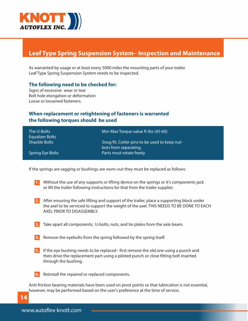
Leaf Type Spring Suspension System– Inspection and Maintenance
The U-Bolts Min-Max Torque value ft-lbs (45-60)Equalizer Bolts Shackle Bolts Snug fit. Cotter pins to be used to keep nut-
bots from separating. Spring Eye Bolts Parts must rotate freely.
1.
2.
3.
4.
5.
6.
As warranted by usage or at least every 5000 miles the mounting parts of your trailer Leaf Type Spring Suspension System needs to be inspected.
Signs of excessive wear or tearBolt hole elongation or deformationLoose or loosened fasteners.
If the springs are sagging or bushings are worn-out they must be replaced as follows:
Without the use of any supports or lifting device on the springs or it's components jack or lift the trailer following instructions for that from the trailer supplier.
After ensuring the safe lifting and support of the trailer, place a supporting block under the axel to be serviced to support the weight of the axel. THIS NEEDS TO BE DONE TO EACH AXEL PRIOR TO DISASSEMBLY.
Take apart all components; U-bolts, nuts, and tie plates from the axle beam.
Remove the eyebolts from the spring followed by the spring itself.
If the eye bushing needs to be replaced - first remove the old one using a punch and then drive the replacement part using a piloted punch or close fitting bolt inserted through the bushing.
Reinstall the repaired or replaced components.
Anti-friction bearing materials have been used on pivot points so that lubrication is not essential, however, may be performed based on the user's preference at the time of service.
The following need to be checked for:
When replacement or retightening of fasteners is warranted the following torques should be used
www.autoflex-knott.com
14
Torsional Axel Suspension Systems
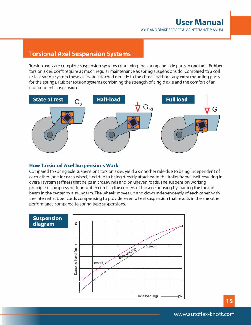
Torsion axels are complete suspension systems containing the spring and axle parts in one unit. Rubber torsion axles don't require as much regular maintenance as spring suspensions do. Compared to a coil or leaf spring system these axles are attached directly to the chassis without any extra mounting parts for the springs. Rubber torsion systems combining the strength of a rigid axle and the comfort of an independent suspension.
Compared to spring axle suspensions torsion axles yield a smoother ride due to being independent of each other (one for each wheel) and due to being directly attached to the trailer frame itself resulting in overall system stiffness that helps in crosswinds and on uneven roads. The suspension working principle is compressing four rubber cords in the corners of the axle housing by loading the torsion beam in the center by a swingarm. The wheels moves up and down independently of each other, with the internal rubber cords compressing to provide even wheel suspension that results in the smoother performance compared to spring type suspensions.
How Torsional Axel Suspensions Work
State of rest Half-load Full load
inward
Suspension diagram
15
User ManualAXLE AND BRAKE SERVICE & MAINTENANCE MANUAL
www.autoflex-knott.com

www.autoflex-knott.com
Autoflex-Knott Limited Warranty
Limited 3 Year WarrantyProven MFG defects not including wearable items.i.e. Berings, Seals, Grease etc.
What Products Are Covered
Limited 5 Year Warranty
Exclusive Remedy
What You Must Do
Exclusions
All Autoflex-Knott trailer axles and suspensions.
Autoflex-Knott warrants to the original purchaser that its bearings and the suspension components shall be free from defects in material and workmanship for a period of five (5) years from the date of first sale of the trailer incorporating such components.
Autoflex-Knott will, at its option, repair or replace the affected components of any defective axle, repair or replace the entire defective axle, or refund the then-current list price of the axle. In all cases, a reasonable time period must be allowed for warranty repairs to be completed. Allowance will only be made for installation costs specifically approved by Autoflex-Knott.
In order to make a claim under these warranties:1. You must be the original purchaser of the vehicle in which the Autoflex-Knott
axles were originally installed. 2. You must promptly notify us within the warranty period of any defect, and provide us
with the axle serial number and any substantiation which may include, but is not limited to, the return of part(s) that we may reasonably request.
3. The axles or suspensions must have been installed and maintained in accordance with
These warranties do not extend to or do not cover defects caused by:1. The trailer wiring to the towing vehicle wiring.2. The attachment of the running gear to the frame.3. Hub imbalance, or any damage caused thereby.4. Parts not supplied by Autoflex-Knott.5. Any damage whatever caused by or related to any alteration of the axle including
welding supplemental brackets to the axle.6. Use of an axle on a unit other than the unit to which it was originally mounted.7. Normal wear and tear.8. Alignment9. Improper installation.10. Wearable brake components
16

11. Unreasonable use (including failure to prove reasonable and necessary maintenance, including required maintenance after ...Prolonged Storage”)
12. Improper wheel nut torque.13. Cosmetic finish or corrosion.
1. In all cases, Autoflex-Knott reserves the right to fully satisfy its obligations under the Limited Warranties by refunding the then-current list price of the defective axle (or, if the axle has been discontinued, of the most nearly comparable current product).
2. Autoflex-Knott reserves the right to furnish a substitute or replacement component or product in the event an axle or any component of the axle is discontinued or is otherwise unavailable.
3. These warranties are nontransferable.
THE FOREGOING WARRANTIES ARE EXCLUSIVE AND IN LIEU OF ALL OTHER WARRANTIES EXCEPT THAT OF TITLE, WHETHER WRITTEN, OR AL OR IMPLIED, IN FACT OR IN LAW (INCLUDING ANY WARRANTY OF MERCHANTABILITY OR FITNESS FOR A PARTICULAR PURPOSE).
These warranties give you specific legal rights, and you may also have other rights which vary from state to state.
THE DURATION OF ANY IMPLIED WARRANTIES, INCLUDING THE IMPLIED WARRANTIES OF MERCHANTABILITY AND FITNESS FOR A PARTICULAR PURPOSE, ARE LIMITED TO THE DURATION OF THE EXPRESS WARRANTIES HEREIN. AUTOFLEX-KNOTT HEREBY EXCLUDES INCIDENTAL AND CONSEQUENTIAL DAMAGES, INCLUDING LOSS OF TIME, INCONVENIENCE, LOSS OF USE, TOWING FEES, TELEPHONE CALLS OR COST OF MEALS, FOR ANYBREACH OF ANY EXPRESS OR IMPLIED WARRANTY, INCLUDING THE IMPLIED WARRANTIES OF MERCHANTABILITY AND FITNESS FOR APARTICULAR PURPOSE.
Some states do not allow limitations on how long an implied warranty lasts, or the exclusion or limitation of incidental or consequential damages, so the above exclusion or limitation may notapply to you.
Inquiries regarding these warranties should be sent to:
Autoflex-Knott Inc.100 Industrial Dr. Fox Lake, WI 53933
Limitations
GENERAL
17
User ManualAXLE AND BRAKE SERVICE & MAINTENANCE MANUAL
www.autoflex-knott.com

Mailing Address:100 Industrial DriveFox Lake, WI 53933Office tel: 920-928-6875Fax: 920-928-6880Email: [email protected]
www.autoflex-knott.com