
1.7 Industrial Redundant Networks - Marc Lee, Belden Automation
34
Industrial Redundant Network Industrial Redundant Network Marc Lee Technical Manager Industrial Networking Technical Manager , Industrial Networking Belden Automation (Asia Pacific) Pted Ltd
Transcript of 1.7 Industrial Redundant Networks - Marc Lee, Belden Automation
Industrial Redundant NetworkIndustrial Redundant Network
Marc Lee Technical Manager Industrial NetworkingTechnical Manager, Industrial NetworkingBelden Automation (Asia Pacific) Pted Ltd

The Green Field Site
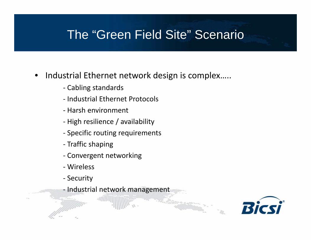
The “Green Field Site” Scenario
• Industrial Ethernet network design is complex• Industrial Ethernet network design is complex…..‐ Cabling standards
‐ Industrial Ethernet Protocols
‐ Harsh environment
‐ High resilience / availability
‐ Specific routing requirementsSpecific routing requirements
‐ Traffic shaping
‐ Convergent networking
Wireless‐Wireless
‐ Security
‐ Industrial network management

The “Green Field Site” Scenario
• You must provide a complete solutionou ust p o de a co p ete so ut o
– How do you design the network?
– How does it all fit together?
How do you give your customers more than they expected?– How do you give your customers more than they expected?
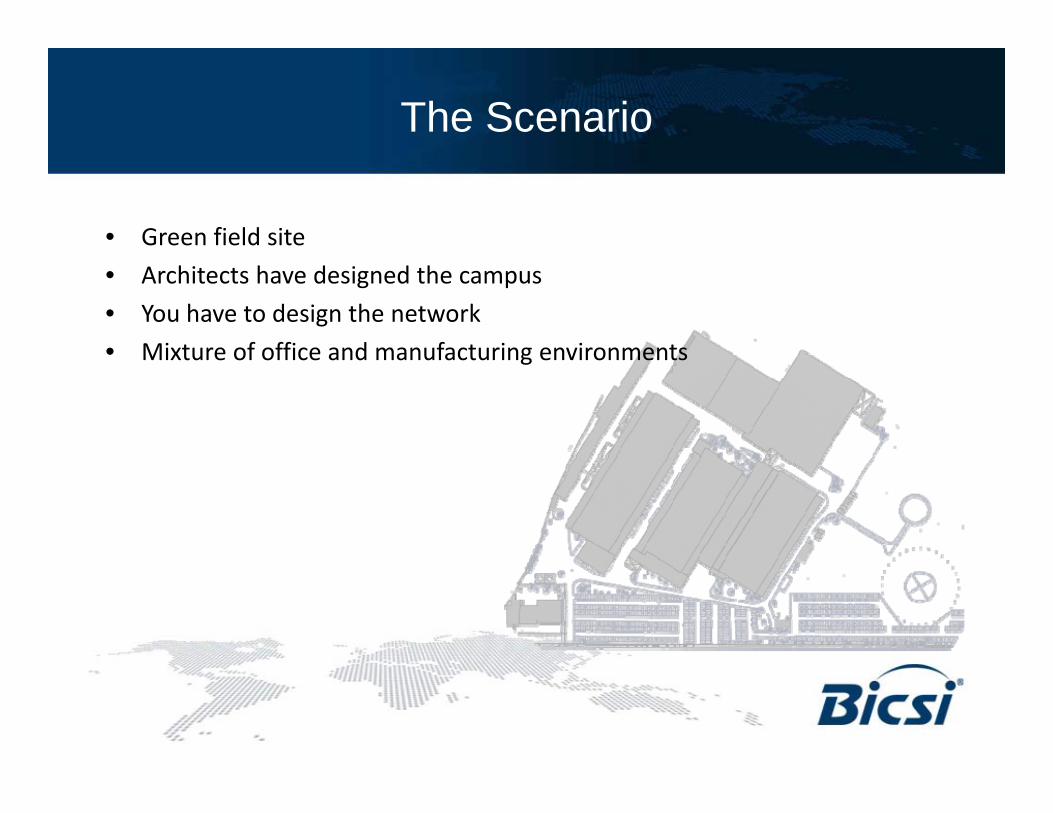
The Scenario
• Green field site
• Architects have designed the campus
• You have to design the network
• Mixture of office and manufacturing environmentsMixture of office and manufacturing environments

Initial Consultation
• Consultation– Customer requirements
– Your experience
Symbiosis– Symbiosis

High Level Office Requirements
• 600 employees using PCs– Company Managementp y g– Internal Sales– Administration– Human Resources– Marketing– IT Department– Research and Development
C t T h i l S t– Customer Technical Support– Security
• Remote connections• Remote connections– Partners– Suppliers– Internet AccessInternet Access– Teleworkers

High Level Factory Requirements
• 99.999% network availability
• Network modifications during live operation
• High temperature
• High electromagnetic interferenceHigh electromagnetic interference
• Manufacturing information available in the offices
• Industrial Ethernet protocol

Site Plan
1. Manufacturing F ilitiFacilities
2. Goods In/Out3
57
3. Stores4. Admin / Human
1
2
36
Resources5. R&D / Tech
1
11
Support6. IT Department
4
87. Sales / Marketing8. Security
8 9

OSI 7 Layer Model
Application
Session
Presentation
Network
Transport
IP
TCP / UDP
Physical
Data Link
Cabling
Ethernet

Redundancy Design looking at …
Causes of network faults…..
3 %Application programs
Application
8 %
7 %
Network operating system
Session
Presentation
10 %
12 %
system
NetworkNetwork
Transport
35 %
25 % Network components
Physical
Data Link
Source: Datacom, Network Management Special

MRP (Media Redundancy Protocol)
• Switched Ethernet networksin ring topology
• Guaranteed failover time of < 200ms / < 500ms (10 i f t l )(10ms in future release)
• Developed by Hirschmann in 1998 (“HiperRing”TM)
• International standard (IEC 62439) since March 2008

IEC 62439
IEC 62439 defines four different redundancy protocols:
MRP, PRP, CRP, BRP
62439 © IEC:2008(E)
CONTENTS
, , ,
CONTENTS
FOREWORD.........................................................8INTRODUCTION....................................................101 Scope 111 Scope.........................................................112 Normative references .........................................113 Terms, definitions, abbreviated terms, acronyms, conventions..124 Concepts for high availability automation networks............225 MRP – Media Redundancy Protocol based on a ring topology .....376 PRP – Parallel Redundancy Protocol............................817 CRP – Cross-network Redundancy Protocol .................... 1038 BRP – Beacon redundancy protocol ........................... 133Annex A (informative) Classification of networks.............. 163A B (i f ti ) A il bilit l l ti 165Annex B (informative) Availability calculations .............. 165Annex C (normative) Network management information base ...... 174

MRP Products
• Many products from different vendors already on the market
Hi h h i l t d MRP i ll f it d it h• Hirschmann has implemented MRP in all of its managed switches
• Portable code for MRP Media Redundancy Protocol is available from IP suppliers
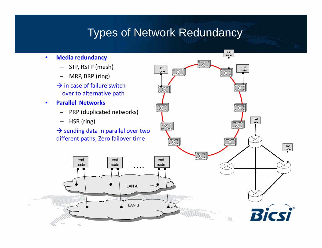
Types of Network Redundancy
• Media redundancy
– STP, RSTP (mesh)
– MRP BRP (ring)MRP, BRP (ring)
in case of failure switchover to alternative path
• Parallel Networks
– PRP (duplicated networks)
– HSR (ring)
sending data in parallel over two different paths Zero failover timedifferent paths, Zero failover time
….end node
endnode
end node
LAN A
LAN B

Failover time of Redundancy Protocols
Protocol StandardTypical re-config time Remark
Available since
any topology / mesh, STP Spanning Tree IEEE802.1 30s diameter limited 1990
RSTP Rapid Spanning Tree IEEE802.1 2sany topology / mesh, diameter limited
2001 / 2004
MRP Media Redundancy Protocol IEC 62439200ms, 500ms (50 switches) ring
1998 (1) / 2007
CRP Cross Network Protocol IEC 624391 s worst casefor 512 end nodes
any topology / duplicated networks
PRP Parallel Redundancy Protocol IEC 62439 0msany topology / duplicated networks -
4 8 ms worst case Two top switches withBRP Beacon Redundancy Protocol IEC 62439
4,8 ms worst casefor 500 end nodes
Two top switches with star, line or ring -
Optimized RSTP Rapid Spanning Tree Future release of IEC 62439 5..20ms per hoplimited to special config set 2008
Fast MRP Media Redundancy Protocol Future release of IEC 624395..20ms (up to 50 switches) ring 2007Fast MRP Media Redundancy Protocol Future release of IEC 62439 (up to 50 switches) ring 2007
HSR High Available Seamless Ring Future release of IEC 62439 0ms ring -
DRP Distributed Redundancy Protocol Future release of IEC 62439100 ms worst casefor 50 switches ring, double ring -
(1) pre standard Hiper Ring since 1998 MRP since 2007(1) pre-standard Hiper Ring since 1998, MRP since 2007
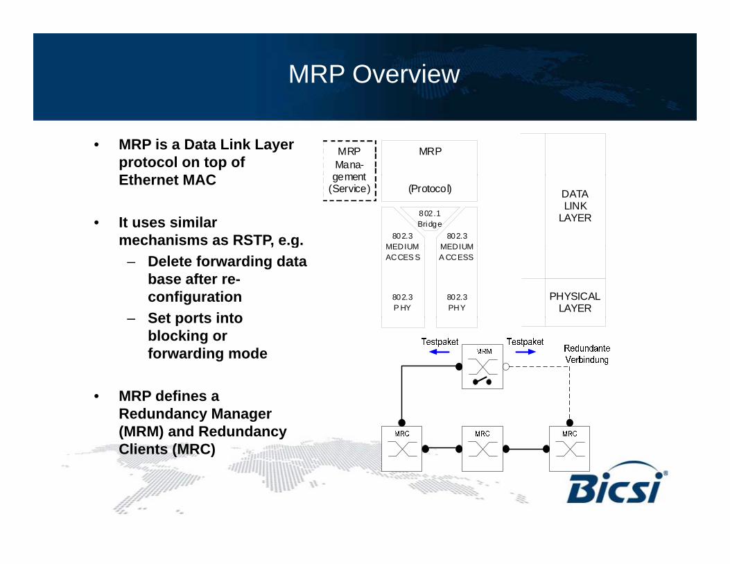
MRP Overview
• MRP is a Data Link Layer protocol on top of Eth t MAC
MRPMana-gement
MRP
Ethernet MAC
• It uses similar mechanisms as RSTP, e.g.
gement(Service) (Protocol) DATA
LINKLAYER
802.3 MEDIUM
802.3 MEDIUM
802.1 Bridge
, g– Delete forwarding data
base after re-configurationSet ports into
PHYSICALLAYER
MEDIUM ACCES S
802.3 P HY
MEDIUM A CCESS
802.3 PHY
– Set ports into blocking or forwarding mode
• MRP defines a Redundancy Manager (MRM) and Redundancy Clients (MRC)
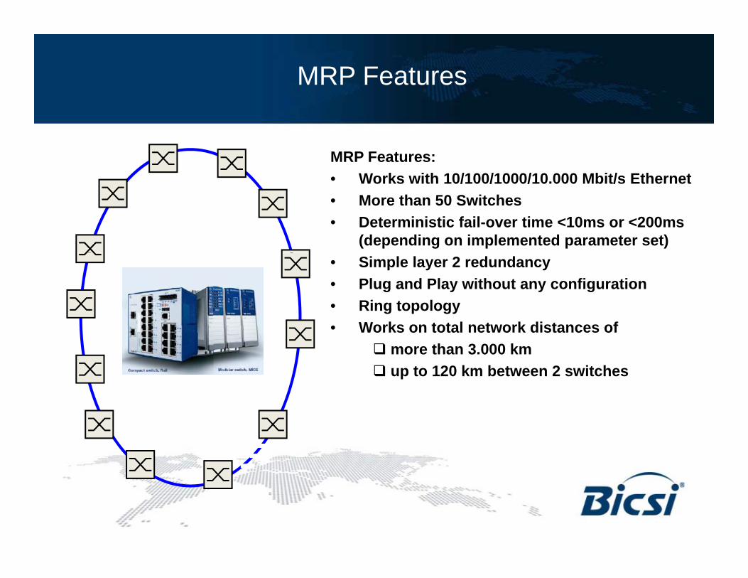
MRP Features
MRP Features:• Works with 10/100/1000/10 000 Mbit/s Ethernet• Works with 10/100/1000/10.000 Mbit/s Ethernet • More than 50 Switches • Deterministic fail-over time <10ms or <200ms
(depending on implemented parameter set)• Simple layer 2 redundancy• Plug and Play without any configuration• Ring topology• Works on total network distances of• Works on total network distances of
more than 3.000 kmup to 120 km between 2 switches
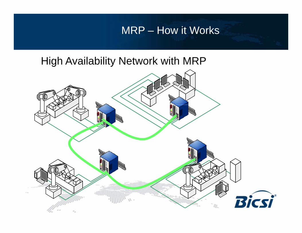
MRP – How it Works
High Availability Network with MRP
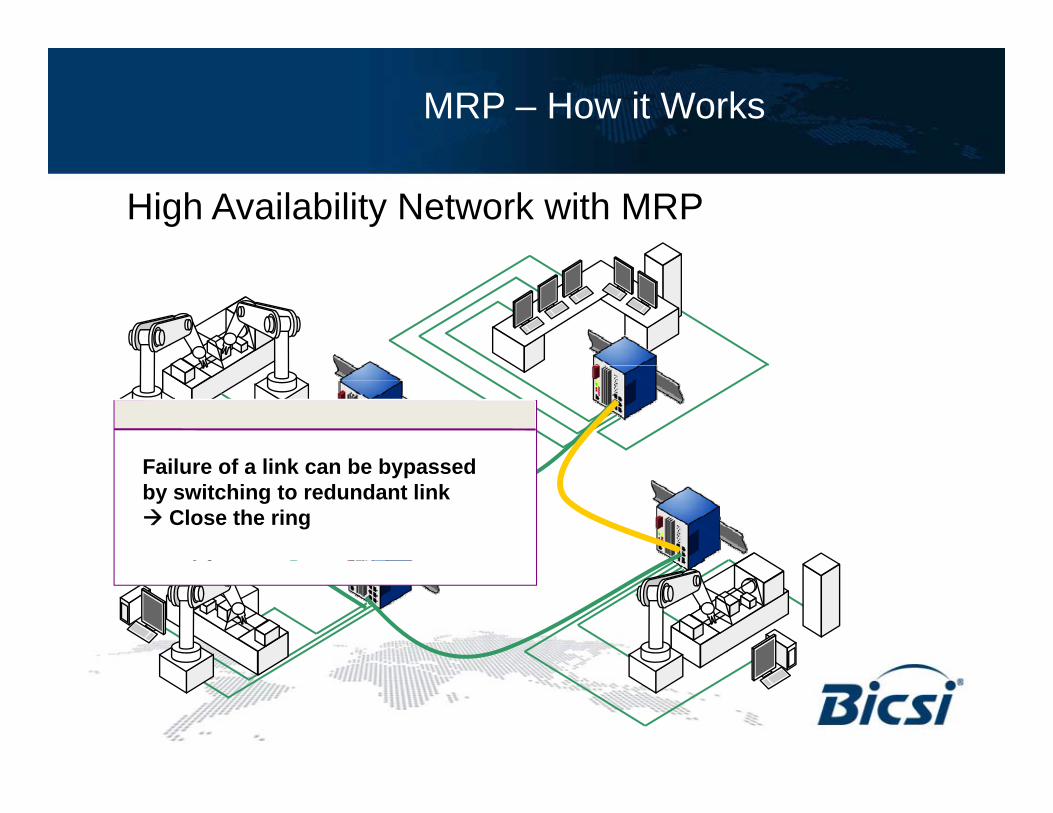
MRP – How it Works
High Availability Network with MRP
Failure of a link can be bypassed by switching to redundant link
Close the ring

MRP – How it Works
High Availability Network with MRP

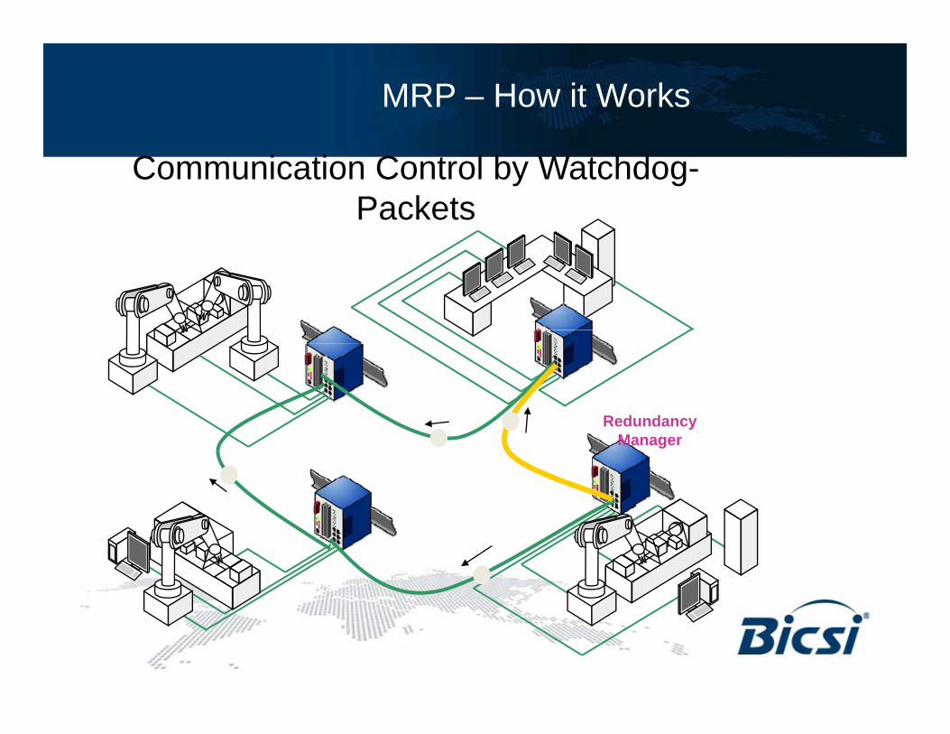
MRP – How it Works
Communication Control by Watchdog-Packets
Redundancy Manager sendsRedundancy Manager sends continuously Watchdog-Packets into the network to check communication
RedundancyManager

MRP – How it Works
Communication Control by Watchdog-Packets
RedundancyManager
MRP – How it Works
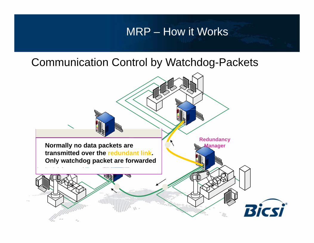
Communication Control by Watchdog-Packets
RedundancyManagerNormally no data packets are
transmitted over the redundant link. Only watchdog packet are forwarded
MRP – How it Works
Communication Control by Watchdog-Packets
RedundancyManager
MRP – How it Works
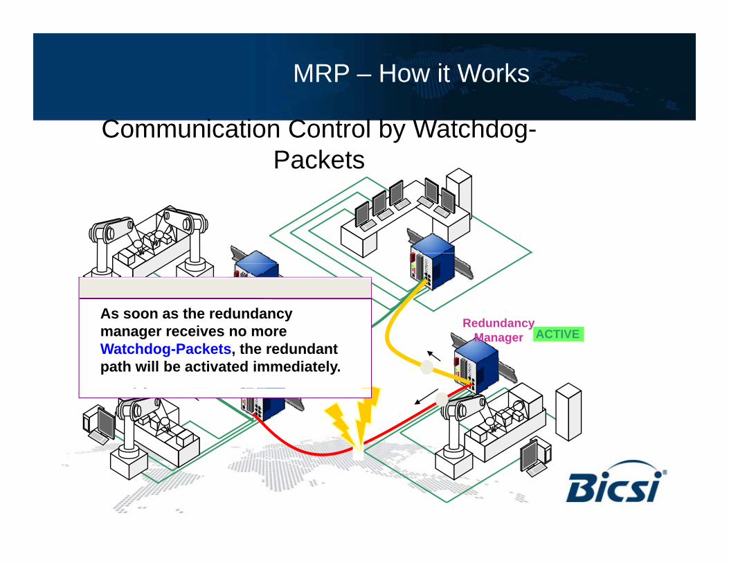
Communication Control by Watchdog-Packets
As soon as the redundancyRedundancy
Manager
As soon as the redundancy manager receives no more Watchdog-Packets, the redundant path will be activated immediately.
ACTIVE

MRP – How it Works
„Self-healing“
RedundancyManager ACTIVE

MRP – How it Works
„Self-healing“
When the failed link goes active RedundancyManager
When the failed link goes active again, the redundancy managerswitches back to normal operation
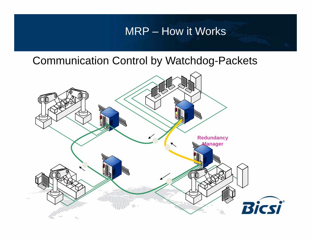
MRP – How it Works
Communication Control by Watchdog-Packets
RedundancyManager
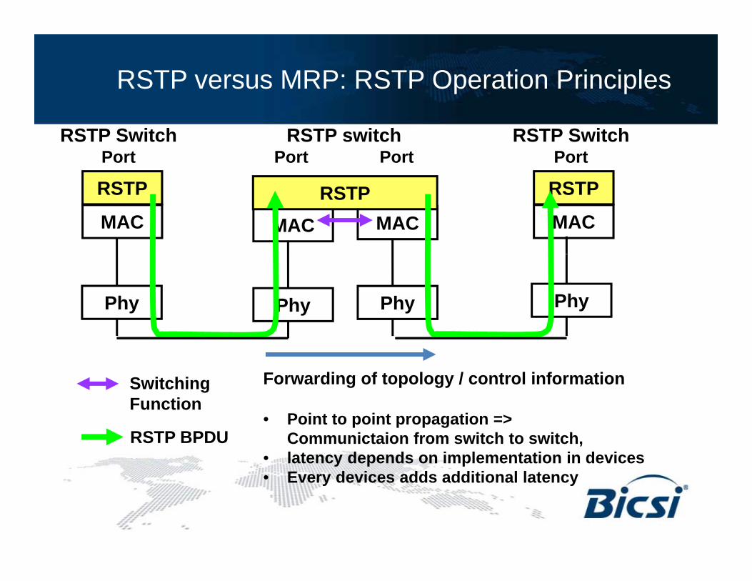
RSTP versus MRP: RSTP Operation Principles
RSTP switchPort Port
RSTP SwitchPort
RSTP Switch Port
RSTP
MAC
RSTP
MACMAC MACRSTP
Phy PhyPhy Phy
Switching F nction
Forwarding of topology / control informationFunction
RSTP BPDU• Point to point propagation =>
Communictaion from switch to switch, • latency depends on implementation in devices
E d i dd dditi l l t• Every devices adds additional latency

RSTP versus MRP: MRP Operation Principles
MRP switchPort Port
MRP Switch Port
MRP SwitchPort
MRP
MAC
MRP
MACMAC MACMRP
Phy PhyPhy Phy
Switching F nction
Forwarding of topology / control informationFunction
MRP DU• Immediate forwarding by switch• Latency nearly independant from number of
cascaded switchL t tl d d i l t ti i• Latency mostly depends on implementation in redundancy manager

RSTP versus MRP
Summary: Comparison MRP versus RSTPSummary: Comparison MRP versus RSTPMRP RSTP
Loops No + Possible ‐
Duplicated packets No + Possible ‐
Deterministic failover time Yes + No ‐
Failover time vs. number of switches in ring Nearly independent
+ Increases with every
‐
add. switch
Failover control based on physical link Yes + Yes +
Failover control based on data link layer Yes + Yes, but slow ‐
Implementation effort and resources needed
Low + Medium ‐

Demo

Q & A