16th NATIONAL POWER SYSTEMS CONFERENCE, … NATIONAL POWER SYSTEMS CONFERENCE, 15th-17th DECEMBER,...
6
Abstract─ The paper presents an analysis of an Indian HVDC system in open access. The system refers to as Gazuwaka back to back HVDC converter terminal. The variation in system operation has been widely studied based on the on line recording of the various pertinent data such as bus voltages at both sides of the converter terminal and also the deviation in nominal operating parameters of the converter. It has been observed that open access operation has resulted in large reactive power mismatch which resulted in the failure of the converter. The comments have been made based on the real time signals which exhibit the improper operational shift in open access. The remedial measures have been suggested based on the experience. Index Terms─ HVDC, real time data, FSC, ESCR. I. INTRODUCTION he open access system operation has posed many operational challenges in real time domain. The various devices connected in power system may not respond in proper manner as prior to open access. This is so as the operaional scenarios are changing regularly with power exchange in inter-area due to varying requirements in terms of system loading. The change in power flow based on demand may affect loading of the lines which may result in either over loading or under loading depending upon whether the system interconnected is heavily loaded or under loaded respectively. Since the loading, in general, results in variation in both real and reactive power flow which may affect, in turn, the bus voltages at various locations in general and in close electrical proximity at the earliest. The change in voltage in case of HVDC system interconnection is very detrimental as it affects the operation of the converters either side. Since the converter bus voltage should be maintained constant in order to maintain the power transfer through HVDC link, the deviation in bus voltage especially at inverter terminal may lead to large variation in reactive power, which may not be possible to be regulated by existing controls by the converter terminal acting as inverter as converter control has design criterion based limitation. ----------------------------------------------------------------------- R. K. Pandey is with Electrical Engineering Dept, Institute of Technology, Banaras Hindu University, Varanasi, India. Email: [email protected] S. K. Soonee, L. Hari, P. Mukherjee and Surajit Banerjee are Power Grid Corporation of India Limited. Earlier operation of HVDC converter was relatively least troublesome, as the bus voltage was maintained and variation even if any was within the capability of the converter control designed. The changed operational scenarios in open access have resulted in wide variation which may not lie in the controllable range of the converter filters etc. This along with the change in other AC system conditions may aggravate the operational band of the controllers at the converter terminals. The terminals either operating as rectifier or inverter may get affected at the interface bus if the generators operating may trip due to improper operation of the connected AC system. The dynamics of AC system may not be known apriori, in situations the open access operation results in extreme operational encroachment in respective subsystems with well defined parameters, this may result in general interarea oscillations. This paper presents an investigation of real life failure of Gazuwaka Back to Back HVDC converter terminal which failed on March 1, 2008 due to operational change in open access. The plots of various variations have been used to analyze the system conditions which are the outcome of open access operational changes seen by the AC system of the converter. The performance evaluation based on the records and data reveals that the reactive power variation has resulted in the failure of the link. The concept of safe system operation with modified controls has been proposed for the improvements in open access operation. II. POWER SYSTEM REPRESENTATION – HVDC INTERCONNECTION The system considered has been represented in Fig. 1. 2X500 MW back-to-back HVDC station at Gajuwaka enables power transfer between Eastern and Southern grids in asynchronous mode. The connectivity of this station with the rest of Eastern grid is depicted in the enclosed diagram. Two nos. shunt reactors each 80MVAR are installed at the converter end (east side) of 400kV Jeypore – Gajuwaka double circuit (D/C) line. These are switchable by reactive power controllers (RPC). At 400kV Jeypore substation, fixed series capacitors (FSC) compensating up to 50% line inductance are installed for Jeypore-Gajuwaka lines and for Jeypore-Meramundali line, 40% compensation has been provided. These capacitors have, however, been kept by- passed on operational grounds, since the occurrence of Ferro resonance in one of the converter blocks at Gajuwaka HVDC station. For 500MW pole-I there are 2X10⁶ MVAR 3/12/24 th harmonic filters and one sub-bank of 106MVAR Study of HVDC System in Open Access -An Indian System Experience R. K. Pandey, Senior Member IEEE, S. K. Soonee, Senior Member IEEE, L. Hari, P. Mukherjee and Surajit Banerjee T 16th NATIONAL POWER SYSTEMS CONFERENCE, 15th-17th DECEMBER, 2010 109 Department of Electrical Engineering, Univ. College of Engg., Osmania University, Hyderabad, A.P, INDIA.
-
Upload
nguyennhan -
Category
Documents
-
view
222 -
download
8
Transcript of 16th NATIONAL POWER SYSTEMS CONFERENCE, … NATIONAL POWER SYSTEMS CONFERENCE, 15th-17th DECEMBER,...

Abstract─ The paper presents an analysis of an Indian HVDC system in open access. The system refers to as Gazuwaka back to back HVDC converter terminal. The variation in system operation has been widely studied based on the on line recording of the various pertinent data such as bus voltages at both sides of the converter terminal and also the deviation in nominal operating parameters of the converter. It has been observed that open access operation has resulted in large reactive power mismatch which resulted in the failure of the converter. The comments have been made based on the real time signals which exhibit the improper operational shift in open access. The remedial measures have been suggested based on the experience. Index Terms─ HVDC, real time data, FSC, ESCR.
I. INTRODUCTION he open access system operation has posed many operational challenges in real time domain. The various devices connected in power system may not respond in
proper manner as prior to open access. This is so as the operaional scenarios are changing regularly with power exchange in inter-area due to varying requirements in terms of system loading. The change in power flow based on demand may affect loading of the lines which may result in either over loading or under loading depending upon whether the system interconnected is heavily loaded or under loaded respectively. Since the loading, in general, results in variation in both real and reactive power flow which may affect, in turn, the bus voltages at various locations in general and in close electrical proximity at the earliest. The change in voltage in case of HVDC system interconnection is very detrimental as it affects the operation of the converters either side. Since the converter bus voltage should be maintained constant in order to maintain the power transfer through HVDC link, the deviation in bus voltage especially at inverter terminal may lead to large variation in reactive power, which may not be possible to be regulated by existing controls by the converter terminal acting as inverter as converter control has design criterion based limitation. ----------------------------------------------------------------------- R. K. Pandey is with Electrical Engineering Dept, Institute of Technology, Banaras Hindu University, Varanasi, India. Email: [email protected] S. K. Soonee, L. Hari, P. Mukherjee and Surajit Banerjee are Power Grid Corporation of India Limited.
Earlier operation of HVDC converter was relatively least troublesome, as the bus voltage was maintained and variation even if any was within the capability of the converter control designed. The changed operational scenarios in open access have resulted in wide variation which may not lie in the controllable range of the converter filters etc. This along with the change in other AC system conditions may aggravate the operational band of the controllers at the converter terminals. The terminals either operating as rectifier or inverter may get affected at the interface bus if the generators operating may trip due to improper operation of the connected AC system. The dynamics of AC system may not be known apriori, in situations the open access operation results in extreme operational encroachment in respective subsystems with well defined parameters, this may result in general interarea oscillations.
This paper presents an investigation of real life failure of Gazuwaka Back to Back HVDC converter terminal which failed on March 1, 2008 due to operational change in open access. The plots of various variations have been used to analyze the system conditions which are the outcome of open access operational changes seen by the AC system of the converter. The performance evaluation based on the records and data reveals that the reactive power variation has resulted in the failure of the link. The concept of safe system operation with modified controls has been proposed for the improvements in open access operation.
II. POWER SYSTEM REPRESENTATION – HVDC INTERCONNECTION
The system considered has been represented in Fig. 1. 2X500 MW back-to-back HVDC station at Gajuwaka enables power transfer between Eastern and Southern grids in asynchronous mode. The connectivity of this station with the rest of Eastern grid is depicted in the enclosed diagram. Two nos. shunt reactors each 80MVAR are installed at the converter end (east side) of 400kV Jeypore – Gajuwaka double circuit (D/C) line. These are switchable by reactive power controllers (RPC). At 400kV Jeypore substation, fixed series capacitors (FSC) compensating up to 50% line inductance are installed for Jeypore-Gajuwaka lines and for Jeypore-Meramundali line, 40% compensation has been provided. These capacitors have, however, been kept by-passed on operational grounds, since the occurrence of Ferro resonance in one of the converter blocks at Gajuwaka HVDC station. For 500MW pole-I there are 2X10⁶ MVAR 3/12/24th harmonic filters and one sub-bank of 106MVAR
Study of HVDC System in Open Access -An Indian
System Experience
R. K. Pandey, Senior Member IEEE, S. K. Soonee, Senior Member IEEE, L. Hari, P. Mukherjee and Surajit Banerjee
T
16th NATIONAL POWER SYSTEMS CONFERENCE, 15th-17th DECEMBER, 2010 109
Department of Electrical Engineering, Univ. College of Engg., Osmania University, Hyderabad, A.P, INDIA.

12/24th harmonic filter at the Eastern bus. For pole-II, 2X110MVAR 3/12/24th harmonic filter and 1X110MVAR 12/24th harmonic filter have been provided on the Eastern side.
Fig.1 Network representation for Gazuwaka Back to Back
It is known that the strength of the AC network at the interface bus of an HVDC substation can be expressed by the short circuit ratio (SCR), defined as the ratio between the short circuit level in MVA at the HVDC substation bus at 1.0 per-unit AC voltage and the DC power in MW. The capacitors and AC filters connected to the AC bus reduce the short circuit level. Thus, the expression effective short circuit ratio (ESCR) is used for the ratio between the short circuit level reduced by the reactive power of the shunt capacitor banks and AC filters connected to the AC bus at 1.0 per-unit voltage and the rated DC power. If S = short circuit level of the AC bus Pd = converter DC power and Qc = reactive compensation of the DC converter then, ESCR = (S – Qc ) / Pd Lower ESCR or SCR means more pronounced interaction between the HVDC substation and the AC network The East bus of the HDVC station at Gajuwaka is at the end of a 225 km long double circuit (D/C) line from the Jeypore 400 kV sub-station. Beyond Jeypore, the only nearby power stations are -
− Upper Indravati Hydro Electric Project (UIHEP)– feeding through 400/220kV ICT and a 72km long single circuit line from Indravati (PG) to Jeypore
− Balimela & Upper Kolab hydro stations – feeding upto Jeynagar through 220kV lines and then connecting with Jeypore through 400/220kV ICTs
The short-circuit levels at Jeypore and Gajuwaka 400kV sub-stations are therefore primarily decided by the total number of units on bar at Balimela, U. Kolab and UIHEP hydro stations which in turn depends on the prevailing season – monsoon or dry as also on the time of the day - peak or lean.
At present, the short-circuit level at Jeypore 400kV bus may vary over a range of 3500MVA to 4500MVA while that at Gajuwaka between 2100MVA to 3200MVA.
Since outage of any transmission element in the vicinity of Jeypore (upstream of the East bus) further reduces the short circuit level at the East bus by increasing the electrical impedance between the HVDC station and the rest of Eastern Grid, the connectivity of the HVDC station with the Eastern Grid can be viewed as relatively weak (SCR may reduce at times to as low as 2.)
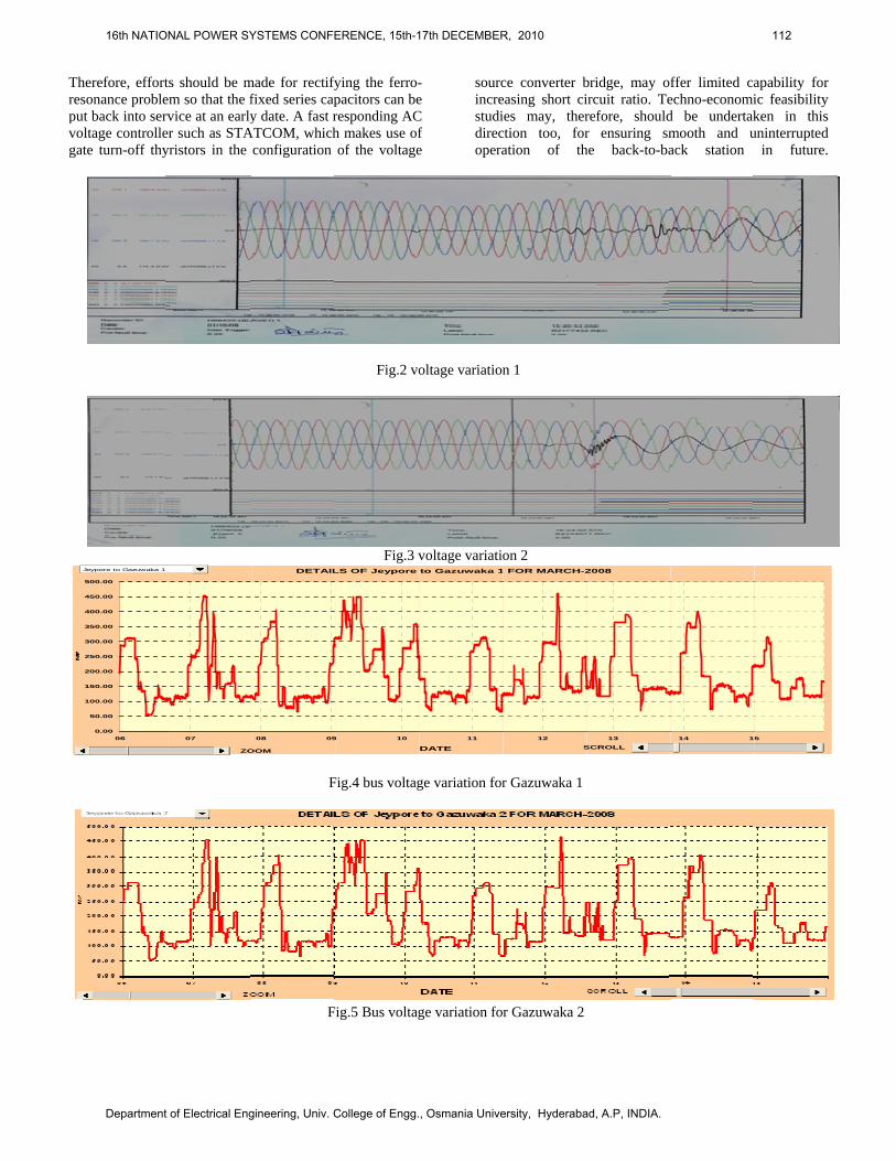
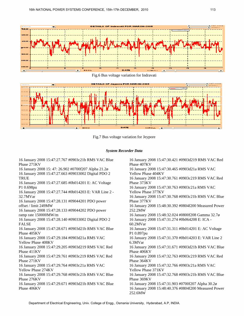
Depending upon economic and operational requirements of power exchange among the interconnected grids, the variation of power flow through the HVDC station may be quite wide. As may be noted from the enclosed graph, export from Eastern region to Southern region through the HVDC station has varied between 200 to 900MW on almost daily basis during the period 6th to 16th March 2008. Because of varying reactive power requirement by the converter, the filters mentioned above are automatically switched in and out. Thus the effective short-circuit ratio (ESCR) at the converter terminal also keeps on changing. With low storage level at the hydro stations during March, only a few number of machines remained on bar at the above mentioned hydro stations, except during evening peak hours. Consequently, the ESCR remained on the lower side, making the AC side voltage prone to fluctuations. The impact was significant enough to cause undesirable voltage variations even at Indravati and Jeypore sub-stations. As can be seen from the graph, the voltage of 400kV Indravati bus varied over a range of 20-25 kV on account of the variations in HVDC power flow while, the fluctuations in Jeypore 400kV voltage was of the order of 30-35 kV.
III. CASE STUDY This section presents analysis of the situations observed in the network shown in Fig.1 on January 16, 2008. The disturbance that occurred on 16.01.08, amply testifies the adverse influence of reduced ESCR on converter performance. Prior to the occurrence, total flow through HVDC Gajuwaka was around 810MW from East to South, with FSCs of Jeypore – Gajuwaka I , II and Jeypore-Meramundali line in by-passed condition. Herein, it may be mentioned that by-passing of the FSCs at Jeypore has the effect of reducing the short circuit level at Gajuwaka East side AC bus by around 600MVA. At UIHEP power station, only two units were generating around 155MW, while the other two units were not in operation. Unlike today, during the period under consideration, two machines of UIHEP
RENGALI(PG)400KV NARENDRAPUR
220KV
MERAMUNDALIBHANJANAGAR
356KM 220KV220KV (OHPC) 400KVBUS-1 400KV (PG)
INDRAVATI
2X315MVATHERUVALI220KV
90KM
220KV 72BUS-2 JEYPUR
220KV
130KM
2X315MVA220KM 6KM
JEYPUR (PG) 400KVJEYNAGAR 220KV(OPTCL)
6KM
2X500 MW 93KMHVDCGAJUWAKA (SR) U.KOLAB
PH
4X80MWBALIMELA PH6X60MW
UIH
EP
4X15
0MW
456KM
16th NATIONAL POWER SYSTEMS CONFERENCE, 15th-17th DECEMBER, 2010 110
Department of Electrical Engineering, Univ. College of Engg., Osmania University, Hyderabad, A.P, INDIA.
used to operate on one 220kV bus, evacuating their generation into Orissa system through 220kV UIHEP – Theruvali D/C line while, the remaining two units operated on another 220kV bus, electrically isolated from the former, and injected their generation into POWERGRID’s 400kV system, through 400/220kV ICTs and then a short 400kV line from UIHEP to Indravati (PG) S/Stn.
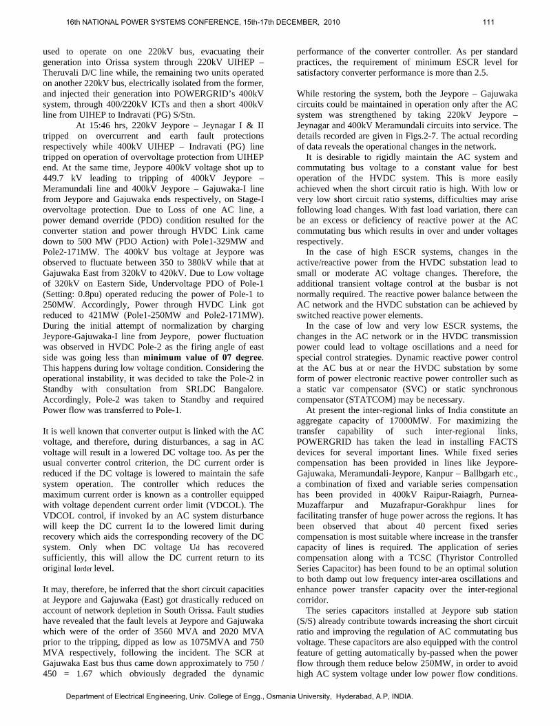
At 15:46 hrs, 220kV Jeypore – Jeynagar I & II tripped on overcurrent and earth fault protections respectively while 400kV UIHEP – Indravati (PG) line tripped on operation of overvoltage protection from UIHEP end. At the same time, Jeypore 400kV voltage shot up to 449.7 kV leading to tripping of 400kV Jeypore – Meramundali line and 400kV Jeypore – Gajuwaka-I line from Jeypore and Gajuwaka ends respectively, on Stage-I overvoltage protection. Due to Loss of one AC line, a power demand override (PDO) condition resulted for the converter station and power through HVDC Link came down to 500 MW (PDO Action) with Pole1-329MW and Pole2-171MW. The 400kV bus voltage at Jeypore was observed to fluctuate between 350 to 380kV while that at Gajuwaka East from 320kV to 420kV. Due to Low voltage of 320kV on Eastern Side, Undervoltage PDO of Pole-1 (Setting: 0.8pu) operated reducing the power of Pole-1 to 250MW. Accordingly, Power through HVDC Link got reduced to 421MW (Pole1-250MW and Pole2-171MW). During the initial attempt of normalization by charging Jeypore-Gajuwaka-I line from Jeypore, power fluctuation was observed in HVDC Pole-2 as the firing angle of east side was going less than minimum value of 07 degree. This happens during low voltage condition. Considering the operational instability, it was decided to take the Pole-2 in Standby with consultation from SRLDC Bangalore. Accordingly, Pole-2 was taken to Standby and required Power flow was transferred to Pole-1. It is well known that converter output is linked with the AC voltage, and therefore, during disturbances, a sag in AC voltage will result in a lowered DC voltage too. As per the usual converter control criterion, the DC current order is reduced if the DC voltage is lowered to maintain the safe system operation. The controller which reduces the maximum current order is known as a controller equipped with voltage dependent current order limit (VDCOL). The VDCOL control, if invoked by an AC system disturbance will keep the DC current Id to the lowered limit during recovery which aids the corresponding recovery of the DC system. Only when DC voltage Ud has recovered sufficiently, this will allow the DC current return to its original Iorder level. It may, therefore, be inferred that the short circuit capacities at Jeypore and Gajuwaka (East) got drastically reduced on account of network depletion in South Orissa. Fault studies have revealed that the fault levels at Jeypore and Gajuwaka which were of the order of 3560 MVA and 2020 MVA prior to the tripping, dipped as low as 1075MVA and 750 MVA respectively, following the incident. The SCR at Gajuwaka East bus thus came down approximately to 750 / 450 = 1.67 which obviously degraded the dynamic
performance of the converter controller. As per standard practices, the requirement of minimum ESCR level for satisfactory converter performance is more than 2.5. While restoring the system, both the Jeypore – Gajuwaka circuits could be maintained in operation only after the AC system was strengthened by taking 220kV Jeypore – Jeynagar and 400kV Meramundali circuits into service. The details recorded are given in Figs.2-7. The actual recording of data reveals the operational changes in the network.
It is desirable to rigidly maintain the AC system and commutating bus voltage to a constant value for best operation of the HVDC system. This is more easily achieved when the short circuit ratio is high. With low or very low short circuit ratio systems, difficulties may arise following load changes. With fast load variation, there can be an excess or deficiency of reactive power at the AC commutating bus which results in over and under voltages respectively.
In the case of high ESCR systems, changes in the active/reactive power from the HVDC substation lead to small or moderate AC voltage changes. Therefore, the additional transient voltage control at the busbar is not normally required. The reactive power balance between the AC network and the HVDC substation can be achieved by switched reactive power elements.
In the case of low and very low ESCR systems, the changes in the AC network or in the HVDC transmission power could lead to voltage oscillations and a need for special control strategies. Dynamic reactive power control at the AC bus at or near the HVDC substation by some form of power electronic reactive power controller such as a static var compensator (SVC) or static synchronous compensator (STATCOM) may be necessary.
At present the inter-regional links of India constitute an aggregate capacity of 17000MW. For maximizing the transfer capability of such inter-regional links, POWERGRID has taken the lead in installing FACTS devices for several important lines. While fixed series compensation has been provided in lines like Jeypore-Gajuwaka, Meramundali-Jeypore, Kanpur – Ballbgarh etc., a combination of fixed and variable series compensation has been provided in 400kV Raipur-Raiagrh, Purnea-Muzaffarpur and Muzafrapur-Gorakhpur lines for facilitating transfer of huge power across the regions. It has been observed that about 40 percent fixed series compensation is most suitable where increase in the transfer capacity of lines is required. The application of series compensation along with a TCSC (Thyristor Controlled Series Capacitor) has been found to be an optimal solution to both damp out low frequency inter-area oscillations and enhance power transfer capacity over the inter-regional corridor.
The series capacitors installed at Jeypore sub station (S/S) already contribute towards increasing the short circuit ratio and improving the regulation of AC commutating bus voltage. These capacitors are also equipped with the control feature of getting automatically by-passed when the power flow through them reduce below 250MW, in order to avoid high AC system voltage under low power flow conditions.
16th NATIONAL POWER SYSTEMS CONFERENCE, 15th-17th DECEMBER, 2010 111
Department of Electrical Engineering, Univ. College of Engg., Osmania University, Hyderabad, A.P, INDIA.
Thresputvogat
MW
J
herefore, effortsonance problet back into servltage controllete turn-off thy
0.00
50.00
100.00
150.00
200.00
250.00
300.00
350.00
400.00
450.00
500.00
06
Jeypore to Gazuwaka 1
ts should be mem so that the fvice at an early
er such as STAyristors in the
07
ZO
made for rectifyfixed series capy date. A fast r
ATCOM, whichconfiguration
F
F
DETAIL
08 09
OOM
fying the ferro-pacitors can beresponding ACh makes use ofof the voltage
Fig.2 vo
Fig.3 v
Fig.4 bus voltag
ig.5 Bus voltag
LS OF Jeypore
9 10
- e C f e
sourcincrestudidirecopera
oltage variation
voltage variatio
ge variation for
ge variation fo
to Gazuwaka 1
11
DATE
ce converter beasing short ciies may, therction too, foration of th
n 1
on 2
r Gazuwaka 1
r Gazuwaka 2
FOR MARCH-2
12
S
bridge, may oircuit ratio. Terefore, shouldr ensuring sm
he back-to-ba
2008
13
SCROLL
ffer limited caechno-economid be undertakmooth and uack station
14 1
apability for ic feasibility ken in this uninterrupted
in future.
5
16th NATIONAL POWER SYSTEMS CONFERENCE, 15th-17th DECEMBER, 2010 112
Department of Electrical Engineering, Univ. College of Engg., Osmania University, Hyderabad, A.P, INDIA.
16 Ph16 16 TR16 P116 3216 off16 ram16 FA16 Ph16 Ye16 Ph16 Ph16 Ye16 Ph16 Ph
January 2008 hase 271KV
January 2008 January 2008
RUE January 2008 0.698pu January 2008
.7MVar January 2008
fset / limit 249MJanuary 2008
mp rate 150000January 2008
ALSE January 2008
hase 405KV January 2008
ellow Phase 40January 2008
hase 411KV January 2008
hase 271KV January 2008
ellow Phase 27January 2008
hase 276KV January 2008
hase 406KV
15:47:27.767 #
15: 47: 26.90215:47:27.663 #
15:47:27.685 #
15:47:27.744 #
15:47:28.131 #MW 15:47:28.133 #
0MW/m 15:47:28.140 #
15:47:28.671 #
15:47:29.184 #8KV 15:47:29.205 #
15:47:29.761 #
15:47:29.764 #4KV 15:47:29.768 #
15:47:29.671 #
#0903c21b RM
2 #0700f207 A#09033002 Dig
#0b014201 E:
#0b014203 E:
#09044201 PD
#09044202 PD
#09033002 Dig
#0903d21b RM
#0903d21a RM
#0903d219 RM
#0903c219 RM
#0903c21a RM
#0903c21b RM
#0903d21b RM
Fig.6 Bus volt
Fig.7 Bus vol
Syste
MS VAC Blue
Alpha 21.2ø gital PDO 2
AC Voltage
VAR Line 2 -
DO power
DO power
gital PDO 2
MS VAC Blue
MS VAC
MS VAC Red
MS VAC Red
MS VAC
MS VAC Blue
MS VAC Blue
tage variation f
ltage variation
em Recorder D
16 JaPhas16 JaYello16 JaPhas16 JaYello16 JaPhas16 Ja252.216 Ja16 Ja60.2M16 JaP1 0.16 Ja6.3M16 JaPhas16 JaPhas16 JaYello16 JaPhas16 Ja16 Ja252.6
for Indravati
for Jeypore
Data
anuary 2008 15e 407KV
anuary 2008 15ow Phase 404Kanuary 2008 15e 373KV
anuary 2008 15ow Phase 377Kanuary 2008 15e 377KV
anuary 2008 152MW anuary 2008 15anuary 2008 15MVar anuary 2008 15.897pu anuary 2008 15
MVar anuary 2008 15e 406KV
anuary 2008 15e 364KV
anuary 2008 15ow Phase 371Kanuary 2008 15e 369KV
anuary 2008 15anuary 2008 156MW
5:47:30.421 #0
5:47:30.465 #0KV 5:47:30.761 #0
5:47:30.763 #0KV 5:47:30.768 #0
5:48:30.392 #0
5:48:32.024 #05:47:31.274 #0
5:47:31.311 #0
5:47:31.370 #0
5:47:31.671 #0
5:47:32.763 #0
5:47:32.766 #0KV 5:47:32.768 #0
5:47:31.903 #05:48:40.376 #0
0903d219 RMS
0903d21a RMS
0903c219 RMS
0903c21a RMS
0903c21b RMS
0804f200 Meas
0800f208 Gamm0b064208 E: IC
0b014201 E: A
0b014203 E: VA
0903d21b RMS
0903c219 RMS
0903c21a RMS
0903c21b RMS
0700f207 Alpha0804f200 Meas
S VAC Red
S VAC
S VAC Red
S VAC
S VAC Blue
sured Power
ma 32.7ø CA -
C Voltage
AR Line 2
S VAC Blue
S VAC Red
S VAC
S VAC Blue
a 30.2ø sured Power
16th NATIONAL POWER SYSTEMS CONFERENCE, 15th-17th DECEMBER, 2010 113
Department of Electrical Engineering, Univ. College of Engg., Osmania University, Hyderabad, A.P, INDIA.
16 January 2008 15:47:34.429 #09044201 PDO power offset / limit 249MW 16 January 2008 15:48:42.022 #0800f208 Gamma 34.1ø 16 January 2008 15:47:34.839 #0b087208 E: Frequency 49.03Hz 16 January 2008 15:47:34.852 #0b04c20e E:Vac imbalance 2.56% 16 January 2008 15:47:34.873 #0b014201 E: AC Voltage P1 0.920pu
16 January 2008 15:47:34.902 #0700f207 Alpha 16.2ø 16 January 2008 15:47:35.180 #0b014203 E:VAR Line 2 58.5MVar 16 January 2008 15:47:35.182 #0b014201 E: AC Voltage P1 0.909pu 16 January 2008 15:48:42.872 #0804f200 Measured Power 252.2MW
IV CONCLUSIONS It is desirable to rigidly maintain the AC system and commutating bus voltage to a constant value for best operation of the HVDC system. This is more easily achieved when the short circuit ratio is high. With low or very low short circuit ratio systems, difficulties may arise following load changes. With fast load variation, there can be an excess or deficiency of reactive power at the AC commutating bus which results in over and under voltages respectively. In the case of high ESCR systems, changes in the active/reactive power from the HVDC substation lead to small or moderate AC voltage changes. Therefore, the additional transient voltage control at the busbar is not normally required. The reactive power balance between the AC network and the HVDC substation can be achieved by switched reactive power elements. In the case of low and very low ESCR systems, the changes in the AC network or in the HVDC transmission power could lead to voltage oscillations and a need for special control strategies. Dynamic reactive power control at the AC bus at or near the HVDC substation by some form of power electronic reactive power controller such as a static var compensator (SVC) or static synchronous compensator (STATCOM) may be necessary. Also, new Flexible AC Transmission System (FACTS) Components such as Unified Power Flow Controller (UPFC) may be used to effectively avoid the both real and reactive power variations. This study is presently being carried out and will be reported soon.
V REFERENCE [1] P. Kundur, Power System Stability and Control, McGraw- Hill,
Companies, Inc, 1994. ISBN 0-07-030958-X. [2] R. K. Pandey, “A Novel Concept for Stabilization of AC/DC Network
with UPFC”, Power Plants and Power Systems Control 2006, pp 1-6, ISBN: 978-0-08-046620-0, ELSEVIER Publications.
[3] System Analysis Report of ELRDC, POWERGRID, March 2008.
VI ACKNOWLEDGEMENTS The Authors express the support of ERLDC and POWERGRID management for sharing the information for academic R & D purpose in national interest.
16th NATIONAL POWER SYSTEMS CONFERENCE, 15th-17th DECEMBER, 2010 114
Department of Electrical Engineering, Univ. College of Engg., Osmania University, Hyderabad, A.P, INDIA.