
16:9 Rear Seat Entertainment Display - Pioneer … · ENGLISH FRANÇAIS DEUTSCH FRANÇAIS ITALIANO...
72
ENGLISH FRANÇAIS DEUTSCH FRANÇAIS ITALIANO NEDERLANDS 16:9 Rear Seat Entertainment Display Écran 16/9 pour passagers arrière Owner’s Manual AVD-W6200 Mode d’emploi This product conforms to CEMA cord colors. Le code couleur des câbles utilisé pour ce produit est conforme à CEMA
Transcript of 16:9 Rear Seat Entertainment Display - Pioneer … · ENGLISH FRANÇAIS DEUTSCH FRANÇAIS ITALIANO...
EN
GLIS
HFR
AN
ÇA
ISD
EU
TS
CH
FR
AN
ÇA
ISIT
ALIA
NO
NED
ER
LAN
DS
16:9 Rear Seat Entertainment Display
Écran 16/9 pour passagers arrière
Owner’s Manual
AVD-W6200Mode d’emploi
This product conforms to CEMA cord colors.Le code couleur des câbles utilisé pour ce produit est conforme à CEMA
1
Contents
Contents ...................................................... 1
Dear Customer ............................................ 2
IMPORTANT SAFEGUARDS .................... 3Please Read All of These Instructions
Regarding Your Display and Retain them for Future Reference ........................ 3
Fitting and Removing the Display .......... 4To fit the display .............................................. 4To remove the display ...................................... 5
IMPORTANT INFORMATION .................... 6About This Product .......................................... 6Precaution .......................................................... 6Important .......................................................... 6After-sales Service for Pioneer Products .......... 7Product registration .......................................... 7
Before Using This Product ...................... 8To Avoid Battery Exhaustion ............................ 8To Protect the LCD Screen of the Display ........ 8When Viewing is Difficult, use [BRIGHTNESS]
and [DIMMER] to Adjust .......................... 8About the RCA Video and Audio Outputs
of this Unit .................................................. 8To Ensure Safe Driving .................................... 9Resetting the System ...................................... 10
- Resetting the Microprocessor- Resetting the Setup Function
Key Finder .................................................. 11Component Parts and Features ........................ 11
Basic Operation ...................................... 12Turn On Power ................................................ 12Volume Adjustment ........................................ 13Selecting a Source ............................................ 13Changing the Wide Screen Mode .................... 14
- Wide Modes Available
Operating the Setup Function ................ 16Dimmer Setting [DIMMER] .......................... 16Entering the Setup Function ............................ 17Functions to be set............................................ 17
- Brightness [BRIGHTNESS]- Contrast [CONTRAST]- Color [COLOR]- Hue [HUE]- Location [LOCATION]- Speaker [SPEAKER]
Using the Display Correctly .................. 19Handling the Display ...................................... 19About the Liquid Crystal Display (LCD)
Screen ...................................................... 20Keeping the Display in Good Condition ........ 20About the Small Fluorescent Tube .................. 20
Connecting the System .......................... 21Names and Functions of Connection
Terminals .................................................. 23Connecting the Power Cable .......................... 24Connection Diagram (VIDEO input) .............. 25Connecting the RCA Audio and
Video Output ............................................ 26
Installation ................................................ 27- When the Display is Installed in the Front
Before Installing and Fixing ............................ 28Before Affixing the Adhesive Tape ................ 28Installing the Display Using the Accessory
Mounting Arm .......................................... 29Installing the Hide-away Unit ........................ 33
- Installation Precautions- Hide-away Unit Installation
Specifications .......................................... 34

2
EN
GLIS
HES
PA
ÑO
LD
EU
TS
CH
FR
AN
ÇA
ISIT
ALIA
NO
NED
ER
LAN
DS
Selecting fine audio equipment such as the unit you’ve just purchased is only the start of yourmusical enjoyment. Now it’s time to consider how you can maximize the fun and excitement yourequipment offers. This manufacturer and the Electronic Industries Association’s ConsumerElectronics Group want you to get the most out of your equipment by playing it at a safe level.One that lets the sound come through loud and clear without annoying blaring or distortion—and,most importantly, without affecting your sensitive hearing.
Sound can be deceiving. Over time your hearing “comfort level” adapts to higher volumes ofsound. So what sounds “normal” can actually be loud and harmful to your hearing. Guard againstthis by setting your equipment at a safe level BEFORE your hearing adapts.
To establish a safe level:
• Start your volume control at a low setting.• Slowly increase the sound until you can hear it comfortably and clearly, and without distor-
tion.
Once you have established a comfortable sound level:• Set the dial and leave it there.
Taking a minute to do this now will help to prevent hearing damage or loss in the future. After all,we want you listening for a lifetime.
We Want You Listening For A LifetimeUsed wisely, your new sound equipment will provide a lifetime of fun and enjoyment. Since
hearing damage from loud noise is often undetectable until it is too late, this manufacturer and theElectronic Industries Association’s Consumer Electronics Group recommend you avoid pro-longed exposure to excessive noise. This list of sound levels is included for your protection.DecibelLevel Example
30 Quiet library, soft whispers40 Living room, refrigerator, bedroom away from traffic50 Light traffic, normal conversation, quiet office60 Air conditioner at 20 feet, sewing machine70 Vacuum cleaner, hair dryer, noisy restaurant80 Average city traffic, garbage disposals, alarm clock at two feet.
THE FOLLOWING NOISES CAN BE DANGEROUS UNDER CONSTANT EXPOSURE90 Subway, motorcycle, truck traffic, lawn mower
100 Garbage truck, chain saw, pneumatic drill120 Rock band concert in front of speakers, thunderclap140 Gunshot blast, jet plane180 Rocket launching pad
Information courtesy of the Deafness Research Foundation.

3
Please Read All of These Instructions Regarding Your Displayand Retain them for Future Reference
1. Read this manual fully and carefully before operating your display.
2. Keep this manual handy for future reference.
3. Pay close attention to all warnings in this manual and follow the instructions care-fully.
4. Never allow others to use the system until they have read and understood theoperating instructions.
5. Do not install the display where it may (i) obstruct the driver’s vision, (ii) impairthe performance of any of the vehicle’s operating systems or safety features,including airbags, or (iii) impair the driver’s ability to safely operate the vehicle.
6. As with any accessory in your vehicle’s interior, the display should not divertyour attention from the safe operation of your vehicle. If you experience difficul-ty in operating the system or reading the display, please park safely before mak-ing adjustments.
7. Do not attempt to install or service your display by yourself. Installation or ser-vicing of the display by persons without training and experience in electronicequipment and automotive accessories may be dangerous and could expose youto the risk of electric shock or other hazards.
8. Please remember to wear your seat belt at all times while operating your vehicle.If you are ever in an accident, your injuries can be considerably more severe ifyour seat belt is not properly buckled.
9. If this product is installed in a place where it is visible to the vehicle’s driver, youMUST always set the [LOCATION] to the [FRONT] setting. Failure to do socould result in distracting images being potentially visible to the driver while thevehicle is in motion.If this product is installed in a place where it is not visible to the vehicle’s driver,then you may choose the [REAR] location setting.
Use of this product is subject to any government laws regarding placement or use.
PIONEER does not accept any liability for any problems, damage or loss incurredas a result of the product being used with an incorrect setting or in violation ofany government laws.
Information to UserAlteration or modifications carried out without appropriate authorization mayinvalidate the user’s right to operate the equipment.
IMPORTANT SAFEGUARDS

To fit the display
1. Fit part 1 of the display into the grooves 2 of the base.
2. Slide the display until it clicks into place.
Precaution:• To prevent failure, be sure to turn the ignition switch or system power OFF before fitting or
removing the display. Also take care not to grip the screen or buttons too firmly or to drop thedisplay.
• Do not let any water get on the terminals on the display or on the cable and do not allow the ter-minals to be shorted by a metal object or the like. This can cause system breakdown.
• Be careful not to touch terminals on the display or on the cable. Doing so may cause connectionfailures. If any terminals are stained, wipe them with a clean dry cloth.
4
EN
GLIS
HES
PA
ÑO
LD
EU
TS
CH
FR
AN
ÇA
ISIT
ALIA
NO
NED
ER
LAN
DS
Fitting and Removing the Display
Base
Mounting arm(supplied)
Connect the cable to the display.

5
Fitting and Removing the Display
Base
Mounting arm(supplied)
Press the lock release buttonwhile holding the display.
Keep holding the button andunplug the connector.
To remove the display
• Pull the lock release lever 3 and hold in that position, then slide the display anddetach it from its base.• To prevent theft of the display, remove the display when leaving the vehicle.
6
EN
GLIS
HES
PA
ÑO
LD
EU
TS
CH
FR
AN
ÇA
ISIT
ALIA
NO
NED
ER
LAN
DS
IMPORTANT INFORMATION
About This Product• Do not place the display in a position where it will impede the driver’s visibility or
affect the operation of your vehicle’s air bags or headrests.• Certain government laws may restrict the placement and use of the display in your car.
Please comply with all applicable laws and regulations in the installation and operationof your display.
Precaution• Always keep the volume low enough for outside sounds to be audible.• Protect the product from moisture.
Important• The serial number of this device is located on the rear of the unit. For your own security
and convenience, be sure to record this number on the enclosed warranty card.
7
Product registrationVisit us at the following site:
1. Register your product. We will keep the details of your purchase on file to help yourefer to this information in the event of an insurance claim such as loss or theft.
2. Receive updates on the latest products and technologies.3. Download owner's manuals, order product catalogues, research new products, and
much more.
IMPORTANT INFORMATION
After-sales Service for Pioneer ProductsPlease contact the dealer or distributor from where you purchased the product for itsafter-sales service (including warranty conditions) or any other information. In casethe necessary information is not available, please contact the companies listed below:Please do not ship your product to the companies at the addresses listed below forrepair without advance contact.
7U.S.A 7CANADAPioneer Electronic (USA) Inc. Pioneer Electronics of Canada, Inc.CUSTOMER SUPPORT CUSTOMER SATISFACTION DIVISION DEPARTMENTP.O. Box 1760 300 Allstate ParkwayLong Beach, CA 90801-1760 Markham, Ontario L3R OP2800 421-1404 (905) 479-4411
1-877-283-5901
For warranty information please see the Limited Warranty sheet included with yourproduct.

To Avoid Battery ExhaustionAlways run the vehicle engine while using this unit. Using this unit without running theengine can result in battery drainage.
To Protect the LCD Screen of the Display• Do not allow direct sunlight to fall on the Display when this unit is not being used.
Extended exposure to direct sunlight can result in LCD screen malfunction due to theresulting high temperatures.
• When using a portable phone, keep the antenna of the portable phone away from theDisplay to prevent disruption of the video by the appearance of spots, colored stripes,etc.
When Viewing is Difficult, use [BRIGHTNESS] and [DIMMER] to AdjustDue to its construction, the view angle of the LCD screen is limited. The viewing angle(vertical and horizontal) can be increased, however, by using [BRIGHTNESS] to adjustthe black density of the video. When using for the first time, adjust the black density inaccordance with the viewing angle (vertical and horizontal) to adjust for clear viewing. [DIMMER] can also be used to adjust the brightness of the LCD screen itself to suit yourpersonal preference.
About the RCA Video and Audio Outputs of this UnitWhen you connect a separate piece of AV equipment such as another display to the RCAvideo and audio output jacks of the hide-away unit, you can select the source for outputwith the SOURCE button.• The video and audio source of the RCA outputs of this unit cannot be selected indepen-
dently.• Volume control buttons will have no effect even if operated.
CAUTION
Never position the display connected to the RCA output jack of the hide-away unit so that the driver can view the picture while the vehicle is moving.
8
EN
GLIS
HES
PA
ÑO
LD
EU
TS
CH
FR
AN
ÇA
ISIT
ALIA
NO
NED
ER
LAN
DS
Before Using This Product

9
Before Using This Product
To Ensure Safe Driving
This unit senses whether the parking brake is on or off. When installed in the FRONT, it isarranged so that video cannot be viewed while the vehicle is moving. The various settingsand adjustments are also not possible while driving. (The following message will be dis-played on the screen while the vehicle is moving.)
Stop the vehicle in a safe place, apply the parking brake and wait for the message to clearbefore starting operation.
Note:• You cannot select wide mode while the message above is displayed on the screen. (Refer to page
14.)

10
EN
GLIS
HES
PA
ÑO
LD
EU
TS
CH
FR
AN
ÇA
ISIT
ALIA
NO
NED
ER
LAN
DS
Resetting the SystemResetting the Microprocessor
Pressing the RESET button lets you reset the microprocessor to its initial settings withoutchanging the setup function settings. Reset the microprocessor in the following cases:When using this product for the first time after installation.When the product fails to operate properly.When strange (incorrect) messages appear on the display.
• To reset the microprocessor, press the RESET button on the unit with a pentip or other pointed instrument.
Resetting the Setup Function
The WIDE/MENU button and the RESET button let you erase all memorized settings andreturn the setup function to their initial (factory) settings without resetting the micro-processor. (Refer to the next page.)
1. Hold the WIDE/MENU down and press the RESET button.
2. Release the RESET button and hold down the WIDE/MENU button for 2seconds.
3. Release the WIDE/MENU button.
RESET button

11
Key Finder
Component Parts and Features
7 Display Unit
1 Signal receptorThis receiver receives signals from aremote control.
2 POWER buttonSwitches power ON/OFF.
3 DIMMER buttonSelects the brightness level.
4 WIDE/MENU buttonChanges the method of enlarging 4:3video to 16:9 video. Pressing this but-ton for 2 seconds, and displayed thesetup function. Once the setup functionis displayed, its function is switchedeach time the button is pressed.
5 Volume control (–/+) buttonsAdjust the volume of the built-inspeaker 8, or change setup items whenthe setup function is displayed.
Note:• Never set the volume so high that you
cannot hear outside traffic and emergencyvehicles.
6 SOURCE buttonSwitches between sources.
7 RESET buttonResets the microprocessor.
8 Built-in speakerOutputs sound from audio equipmentconnected to this product.

WARNINGIf this product is installed in a place where it is visible to the vehicle’s driver,you MUST always set the [LOCATION] to the [FRONT] setting. Failure todo so could result in distracting images being potentially visible to the driverwhile the vehicle is in motion.
If this product is installed in a place where it is not visible to the vehicle’sdriver, then you may choose the [REAR] location setting.
Use of this product is subject to any government laws regarding placementor use.
PIONEER does not accept any liability for any problems, damage or lossincurred as a result of the product being used with an incorrect setting or inviolation of any government laws.
Be sure to perform this setting. (Refer to page 18.)
Turn On PowerRemember to start the car engine before turning on the power to preserve battery life.
1. Start the car engine.
2. Turn on the system.Press the POWER button.
To turn off the system, press the POWER button again.
ACC ON
LOCK
START
12
EN
GLIS
HES
PA
ÑO
LD
EU
TS
CH
FR
AN
ÇA
ISIT
ALIA
NO
NED
ER
LAN
DS
Basic Operation

13
Basic Operation
Volume AdjustmentAdjust the volume of audio output from the built-in speaker.
• Raise or lower the speaker volume.
The volume of the built-in speaker can be adjusted in a range of 0 to 30. (The volume levelwill be displayed for about 4 seconds.)
Selecting a Source
• Select the desired source.
Each press of the SOURCE button selects the desired source in the following order:[VIDEO1] = [VIDEO2] = Exit to [VIDEO1]
Note:• [VIDEO1] and [VIDEO2] are audio and video from the AV equipment connected to the VIDEO1
or VIDEO2 input terminal. (Refer to page 23.)• Verify the correct connection with the AV equipment connected to VIDEO1 or VIDEO2.
VIDEO1
VOL 12

14
EN
GLIS
HES
PA
ÑO
LD
EU
TS
CH
FR
AN
ÇA
ISIT
ALIA
NO
NED
ER
LAN
DS
Changing the Wide Screen ModeYou can change the way in which normal video (aspect ratio 4:3) enlarges to wide video(16:9). Select wide modes to suit the kind of video you are viewing.
1. Display a source to view. (Refer to the previous page.)
2. Select a wide mode.
Each press of the WIDE/MENU button selects the wide mode in the following order:[FULL] = [JUST] = [CINEMA] = [ZOOM] = [NORMAL] = Exit to [FULL]
Note:• Settings are stored for each source (VIDEO1, VIDEO2).• When video is viewed in a wide mode that does not match its original aspect ratio, it may appear
differently.• Remember that using the wide mode feature of this system for commercial or public viewing pur-
poses may constitute an infringement on the author’s rights protected by the Copyright Law.

15
Wide Modes Available
Note:• Video will appear roughened when viewed in CINEMA or ZOOM mode.
NORMALVideo with an aspect ratio of 4:3appears without enlarging. Enjoyviewing TV in the same video as itis broadcast.
ZOOMVideo with an aspect ratio of 4:3enlarges with the same aspect ratioin both vertical and horizontaldirections. This wide mode is suit-ed for horizontally long video,such as movies, in which titlesoverlap the video.
CINEMAVideo enlarges vertically with aaspect ratio falling between FULLand ZOOM. This wide mode issuited for horizontally long video,such as movies, in which titles aredisplayed in black areas outsidethe video.
JUSTVideo appears more extended hor-izontally as it gets closer to bothedges of the screen. Because videoappears in about the same size asregular video around the middle ofthe screen, enjoy viewing it with-out feeling out of place.
FULLVideo with an aspect ratio of 4:3enlarges only horizontally. Enjoyviewing video widened withoutmissing parts.
Basic Operation

16
EN
GLIS
HES
PA
ÑO
LD
EU
TS
CH
FR
AN
ÇA
ISIT
ALIA
NO
NED
ER
LAN
DS
Operating the Setup Function
Dimmer Setting [DIMMER]Viewing can become difficult after extended video viewing if the screen is too bright atnight or when ambient light darkens. You can select the brightness level from three set-tings; HIGH, MID and LOW viewing.
1. Display a source to view. (Refer to page 13.)
2. Select a brightness level.
Each press of the DIMMER button selects the brightness level in the following order:[HIGH] = [MID] = [LOW] = Exit to [HIGH]
Note:• Settings are stored by the source and the lighting switch (VIDEO1/VIDEO2, Car lights on/Car
lights off).

17
Operating the Setup Function
Entering the Setup FunctionThis system offers a number of functionality setup and adjustment features to make it easi-er to use. Customize the settings to suit your taste and environment.
1. Display the setup function.
Press and hold the WIDE/MENU button for 2 seconds.
2. Select a function.
Each press of the WIDE/MENU button selects the desired function in the following order:[BRIGHTNESS] = [CONTRAST] = [COLOR] = [HUE] = [LOCATION] =[SPEAKER] = Exit the setup function.
3. Adjust the setting level. / Switch the setting.
Pressing the Volume control (–/+) buttons adjusts the setting level or switches the setting.
Functions to be setFor the operations of the following functions, refer to the explanation above.Settings for [BRIGHTNESS], [CONTRAST], [COLOR] and [HUE] are stored by thesource and the lighting switch (VIDEO1/VIDEO2, Car lights on/Car lights off).

18
EN
GLIS
HES
PA
ÑO
LD
EU
TS
CH
FR
AN
ÇA
ISIT
ALIA
NO
NED
ER
LAN
DS
Brightness [BRIGHTNESS]
You can make black appear darker or lighter (–24 to +24).
Contrast [CONTRAST]
You can make narrow or widen the gap between black and white (darken) (–24 to +24).
Color [COLOR]
You can make colors appear lighter or darker (–24 to +24).
Hue [HUE]
You can adjust the red or green of the picture (–24 to +24).
Location [LOCATION]
When using the display for the first time, set its mounting location.[FRONT]: This product is installed on the dashboard or another location where the drivercan see the display.[REAR]: This product is installed in a location for viewing by rear seat passengers (in alocation where the driver cannot see the display).
Note:• When [LOCATION] has been set to [FRONT], the video cannot be viewed while the vehicle is
moving. The setup function screen also cannot be displayed while the vehicle is moving. ([ATTEN-TION] will be displayed while the vehicle is moving.)Stop the vehicle in a safe place, apply the parking brake and wait for [ATTENTION] to be clearedbefore starting operation.
Speaker [SPEAKER]
You can select [ON] or [OFF] for the audio from the built-in speaker.

19
CAUTION
• If moisture or foreign matter should get inside the unit, turn OFF the powerimmediately and consult your dealer or the nearest authorized PIONEERservice facility. Using the unit in this condition may result in a fire, electricshock or other failure.
• If you notice smoke, a strange noise or smell, or any other abnormal signsfrom the display, turn OFF the power immediately and consult your dealeror the nearest authorized PIONEER service facility. Using the unit in thiscondition may result in failure of the system.
• Do not remove the rear cover of the display, as there are high-voltage com-ponents inside which may cause an electric shock. Be sure to consult yourdealer or the nearest authorized PIONEER service facility for internalinspection, adjustments or repairs.
Handling the Display• When the display is not being used, never leave it under the direct sunlight or in extreme
temperatures.• The display should be used within the temperature ranges shown below.
Operating temperature range: –10 to +50 °C [+14 to 122 °F]Storage temperature range: –20 to +80 °C [–4 to 176 °F]At temperatures higher or lower than the operating temperature range, the display maynot operate normally.
• The LCD screen of this product is exposed to improve view ability in the vehicle. Do notpush the LCD screen strongly. This could break it.
• Do not touch the LCD screen. This could cause scratches or soiling.
Using the Display Correctly
20
EN
GLIS
HES
PA
ÑO
LD
EU
TS
CH
FR
AN
ÇA
ISIT
ALIA
NO
NED
ER
LAN
DS
About the Liquid Crystal Display (LCD) Screen• If the display is near the vent of an air conditioner when it is deployed, make sure that
air from the air conditioner is not blowing on it. Heat from the heater may break theLCD screen, and cool air from the cooler may cause moisture to form inside the displayresulting in possible damage. Also, if the display is cooled down by the cooler, thescreen may become dark, or the life span of the small fluorescent tube used inside thedisplay may be shortened.
• Small black dots or white dots (bright dots) may appear on the LCD screen. These aredue to the characteristics of the LCD screen and do not indicate a problem with the dis-play.
• At low temperatures, the LCD screen may be dark for a while after the power is turnedON.
• The LCD screen will be difficult to see if it is exposed to direct sunlight.
Keeping the Display in Good Condition• When removing dust from the screen or cleaning the display, first turn the system power
OFF, then wipe with a soft dry cloth. • When wiping the screen, take care not to scratch the surface. Do not use harsh or abra-
sive chemical cleaners.• Do not use a wet cloth for cleaning. Do not use organic solvents, such as benzine, thin-
ner.
About the Small Fluorescent Tube• A small fluorescent tube is used inside the display to illuminate the LCD screen.
* The fluorescent tube is an expendable part and has a limited service life.* The fluorescent tube should last for approximately 10,000 hours, depending on oper-
ating conditions. (Using the display at low temperatures reduces the service life of thefluorescent tube.)
* When the fluorescent tube reaches the end of its useful life, the screen will be darkand the image will no longer be projected. If this happens, consult your dealer or thenearest authorized PIONEER service facility.

21
Connecting the System
CAUTION• PIONEER does not recommend that you install or service your display your-
self. Installing or servicing the product may expose you to risk of electricshock or other hazards. Refer all installation and servicing of your display toauthorized Pioneer service personnel.
• Secure all wiring with cable clamps or electrical tape. Do not allow any barewiring to remain exposed.
• Do not drill a hole into the engine compartment to connect the yellow lead ofthe unit to the vehicle battery. Engine vibration may eventually cause theinsulation to fail at the point where the wire passes from the passenger com-partment into the engine compartment. Take extra care in securing the wireat this point.
• It is extremely dangerous to allow the display lead to become wound aroundthe steering column or gearshift. Be sure to install the display in such a waythat it will not obstruct driving.
• Make sure that wires will not interfere with moving parts of the vehicle, suchas the gearshift, parking brake or seat sliding mechanism.
• Do not shorten any leads. If you do, the protection circuit may fail to workproperly.
22
EN
GLIS
HES
PA
ÑO
LD
EU
TS
CH
FR
AN
ÇA
ISIT
ALIA
NO
NED
ER
LAN
DS
Note:• This unit is for vehicles with a 12-volt battery
and negative grounding. Before installing it in arecreational vehicle, truck, or bus, check the bat-tery voltage.
• To avoid shorts in the electrical system, be sureto disconnect the ≠ battery cable before begin-ning installation.
• Refer to the owner’s manual for details on con-necting other units, then make connections cor-rectly.
• Secure the wiring with cable clamps or adhesivetape. To protect the wiring, wrap adhesive tapearound them where they lie against metal parts.
• Route and secure all wiring so it cannot touchany moving parts, such as the gear shift, hand-brake and seat rails. Do not route wiring inplaces that get hot, such as near the heater outlet.If the insulation of the wiring melts or gets torn,there is a danger of the wiring short-circuiting tothe vehicle body.
• Don’t pass the yellow lead through a hole intothe engine compartment to connect to the battery.This will damage the lead insulation and cause avery dangerous short.
• Do not shorten any leads. If you do, the protec-tion circuit may fail to work when it should.
• Never feed power to other equipment by cuttingthe insulation of the power supply lead of theunit and tapping into the lead. The current capac-ity of the lead will be exceeded, causing over-heating.
• When replacing a fuse, be sure to use only fusesof the rating prescribed on the fuse holder.
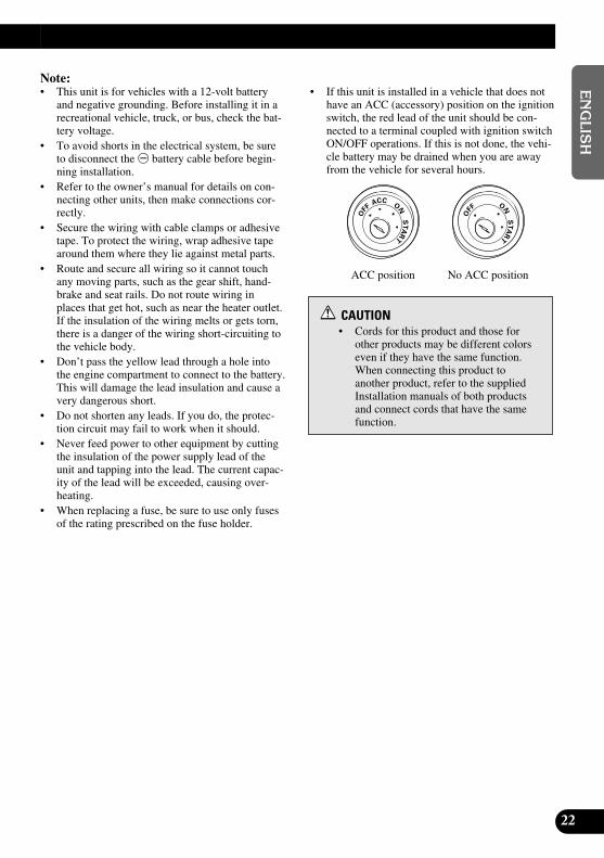
• If this unit is installed in a vehicle that does nothave an ACC (accessory) position on the ignitionswitch, the red lead of the unit should be con-nected to a terminal coupled with ignition switchON/OFF operations. If this is not done, the vehi-cle battery may be drained when you are awayfrom the vehicle for several hours.
CAUTION• Cords for this product and those for
other products may be different colorseven if they have the same function.When connecting this product to another product, refer to the suppliedInstallation manuals of both productsand connect cords that have the samefunction.
No ACC positionACC position
ONS
TA
R
T
OFF
ACCON
STA
R
T
OFF

23
Connecting the System
Names and Functions of Connection Terminals
7 Hide-away Unit
1 VIDEO1 RCA video input (yellow)Receives video, as from a VCR, DVD orother AV equipment.
2 VIDEO1 RCA audio input (white,red)Receives stereo audio, as from a VCR,DVD or other AV equipment.
3 VIDEO2 RCA video input (yellow)Receives video, as from a VCR, DVD orother AV equipment.
4 VIDEO2 RCA audio input (white,red)Receives stereo audio, as from a VCR,DVD or other AV equipment.
5 Power SupplyReceives the power cable supplied.
6 Display output (white)Connects to the display unit.
7 RCA video output (yellow)Connects to other AV equipment. Videoselected with this display is directed to thisterminal.
8 RCA audio output (white, red)Connects to other AV equipment. Audioselected with this display is directed tothese terminals.

24
EN
GLIS
HES
PA
ÑO
LD
EU
TS
CH
FR
AN
ÇA
ISIT
ALIA
NO
NED
ER
LAN
DS
Power cable
Fuse resistor
Light greenUsed to detect the ON/OFF status of the parkingbrake. This lead must be connected to the powersupply side of the parking brake switch.
Parking brake switch
Power supply side
Ground side
Hide-away Unit
Orange/whiteTo lighting switch terminal.
YellowTo the terminal always supplied with power regard-less of ignition switch position.
Connecting method
Clamp the parkingbrake switch powersupply side lead.
Clamp firmlywith needle-nosedpliers.
RedTo the electric terminal controlled by the ignitionswitch (12 V DC) ON/OFF.
Do not connect this lead to power source terminalsto which power is continuously supplied. If the leadis connected to such terminals, the battery may bedrained.
Black (ground)To vehicle (metal) body.
Note:• The position of the parking brake switch
depends on the vehicle model. For details,consult the vehicle Owner’s Manual ordealer.
Connecting the Power Cable
Fuse resistor
Fuse holder (4A)

25
Connecting the System
Connection Diagram (VIDEO input)
Display Unit
Note:• This system has display mounting location [LOCATION] settings [FRONT/REAR]. Be sure to
complete these setting after the system has been installed. (Refer to page 18.)
White
Commerciallyavailable portablevideo componentwith RCA output
To video output
To audio output
VIDEO2 INPUT
VIDEO1 INPUT
Hide-away Unit
3 m (9ft 10in.)
VIDEO1 RCA audio input (white, red)
VIDEO1 RCA video input (yellow)
Commercial RCA cable(sold separately)

26
EN
GLIS
HES
PA
ÑO
LD
EU
TS
CH
FR
AN
ÇA
ISIT
ALIA
NO
NED
ER
LAN
DS
Connecting the RCA Audio and Video Output
Power cable(Refer to page 22.)
Hide-away Unit
RCA video output (yellow)RCA audio output (white, red)
Commercial RCA cable(sold separately)
To audio input (R)
To audio input (L)
To video input
Second display, videodeck, etc.
27
Installation
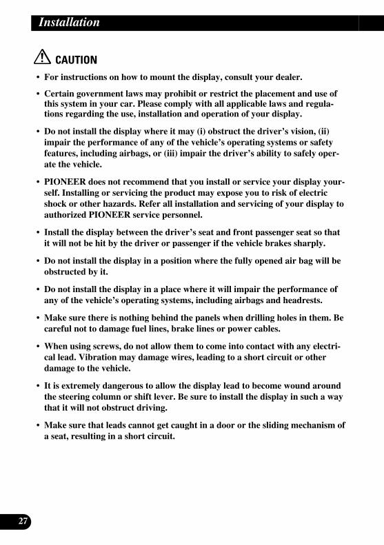
CAUTION• For instructions on how to mount the display, consult your dealer.
• Certain government laws may prohibit or restrict the placement and use ofthis system in your car. Please comply with all applicable laws and regula-tions regarding the use, installation and operation of your display.
• Do not install the display where it may (i) obstruct the driver’s vision, (ii)impair the performance of any of the vehicle’s operating systems or safetyfeatures, including airbags, or (iii) impair the driver’s ability to safely oper-ate the vehicle.
• PIONEER does not recommend that you install or service your display your-self. Installing or servicing the product may expose you to risk of electricshock or other hazards. Refer all installation and servicing of your display toauthorized PIONEER service personnel.
• Install the display between the driver’s seat and front passenger seat so thatit will not be hit by the driver or passenger if the vehicle brakes sharply.
• Do not install the display in a position where the fully opened air bag will beobstructed by it.
• Do not install the display in a place where it will impair the performance ofany of the vehicle’s operating systems, including airbags and headrests.
• Make sure there is nothing behind the panels when drilling holes in them. Becareful not to damage fuel lines, brake lines or power cables.
• When using screws, do not allow them to come into contact with any electri-cal lead. Vibration may damage wires, leading to a short circuit or otherdamage to the vehicle.
• It is extremely dangerous to allow the display lead to become wound aroundthe steering column or shift lever. Be sure to install the display in such a waythat it will not obstruct driving.
• Make sure that leads cannot get caught in a door or the sliding mechanism ofa seat, resulting in a short circuit.

28
EN
GLIS
HES
PA
ÑO
LD
EU
TS
CH
FR
AN
ÇA
ISIT
ALIA
NO
NED
ER
LAN
DS
• If this product is installed in a place where it is visible to the vehicle’s driver,you MUST always set the [LOCATION] to the [FRONT] setting. Failure todo so could result in distracting images being potentially visible to the driverwhile the vehicle is in motion.If this product is installed in a place where it is not visible to the vehicle’sdriver, then you may choose the [REAR] location setting.Use of this product is subject to any government laws regarding placementor use.PIONEER does not accept any liability for any problems, damage or lossincurred as a result of the product being used with an incorrect setting or inviolation of any government laws.
• To ensure proper installation, use the supplied parts in the manner specified.If any parts other than the supplied ones are used, they may damage internalparts of the unit or they may work loose and the unit may come off.
When the Display is Installed in the Front
• To ensure safe driving, be sure to install the display in a position that meetsthe following conditions. * Where it does not obstruct the driver’s vision and impede the safe opera-
tion of the vehicle.* Where the front of the car is within the driver’s field of vision when look-
ing at the display.* Where the display does not protrude above the front of the hood as viewed
by the driver.
Before Installing and Fixing• Make temporary connections first to check that the unit and system are working properly.• Press the RESET button with the tip of a ball-point pen or similar object, when a con-
nection is completed.
Before Affixing the Adhesive Tape• Make sure the surface is free of moisture, dust, grime, oil, etc. before affixing the tape.

29
Installing the Display Using the Accessory Mounting ArmUse the supplied mounting arm to fasten the display to the seat.
CAUTION• If you are unsure of the suitability of the mounting arm for your car, as may
be the case with custom-made seating, consult your nearest dealer.
• Usage or placement of this product must strictly adhere to the figure below.PIONEER does not accept any liability for any problems, damage or lossincurred as a result of the incorrect installation or usage of this product.
• When using this system, ensure that your seatbelt is securely fastened.Sudden braking and any other accident may cause your body to collide withthe system. By not fastening your seatbelt correctly you increase yourchances of serious injury in the event of an accident.
• Keep the supplied hexagonal wrench out of the reach of children. Should thewrench be swallowed or otherwise cause injury, immediately consult a doc-tor.
• Do not remove the display from the mounting arm while driving.
• Make sure to tighten the screws on the mounting arm before using.
• Do not attempt to disassemble or convert the mounting arm.
• Do not apply excessive loads to the mounting arm.
• The supplied mounting arm must be installed on the boots under the head-rest. If these boots are not installed on your car seat, you cannot install themounting arm. The mounting arm can also not be installed on shaftlessheadrests or seats with unified headrests.
• The supplied mounting arm may not be installed on the seat which hasunique shaped shafts or boots.
• Do not install the mounting arm on seats which move the headrest towardthe passenger’s head to prevent neck-injuries (whiplash) upon impact.
Installation

1. Push the lock release button, then slide and remove the headrest upward.
Note:• The supplied mounting arm may not be installed on seats where the lock release button does not
face outside.
2. Adjust the shaft guides so that the shafts pass through the mounting arm.Choose holes that match the shafts, then adjust the positions of the shaft guides to matchthe width between the shafts.
77 Removing and setting the shaft guides.
Note:• The suitable width between the shafts is between 120mm (4-3/4 in) and 190mm (11-5/8 in).
30
EN
GLIS
HES
PA
ÑO
LD
EU
TS
CH
FR
AN
ÇA
ISIT
ALIA
NO
NED
ER
LAN
DS
Head rest
Shaft
Boots
Examples: Positions of the shaft guides
Choose a hole that matches the shaft diameter.
Adjust the position of the shaft guides to the length shown.
To remove the shaft guides,push them from the bottomside of the mounting arm.
You can slide the left side guide to make adjustments.
Lock the shaft guides in position.
You can change the directionof the left side guide.
You cannot change thedirection of the right sideguide.
The narrowest model (120 mm [4-3/4 in])
The widest model (190 mm [11-5/8 in])
The right side guide canonly be set at either end.
31
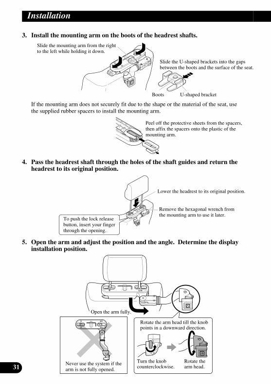
3. Install the mounting arm on the boots of the headrest shafts.
If the mounting arm does not securely fit due to the shape or the material of the seat, usethe supplied rubber spacers to install the mounting arm.
4. Pass the headrest shaft through the holes of the shaft guides and return theheadrest to its original position.
5. Open the arm and adjust the position and the angle. Determine the displayinstallation position.
Installation
Slide the mounting arm from the rightto the left while holding it down.
Slide the U-shaped brackets into the gapsbetween the boots and the surface of the seat.
Boots U-shaped bracket
Peel off the protective sheets from the spacers,then affix the spacers onto the plastic of themounting arm.
To push the lock releasebutton, insert your fingerthrough the opening.
Lower the headrest to its original position.
Remove the hexagonal wrench fromthe mounting arm to use it later.
Rotate the arm head till the knobpoints in a downward direction.
Rotate thearm head.
Turn the knobcounterclockwise.
Open the arm fully.
Never use the system if thearm is not fully opened.
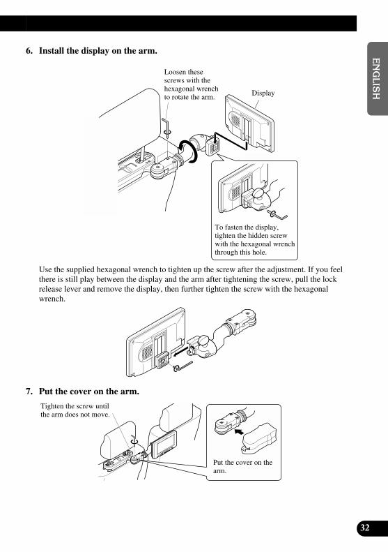
6. Install the display on the arm.
Use the supplied hexagonal wrench to tighten up the screw after the adjustment. If you feelthere is still play between the display and the arm after tightening the screw, pull the lockrelease lever and remove the display, then further tighten the screw with the hexagonalwrench.
7. Put the cover on the arm.
32
EN
GLIS
HES
PA
ÑO
LD
EU
TS
CH
FR
AN
ÇA
ISIT
ALIA
NO
NED
ER
LAN
DS
Loosen thesescrews with thehexagonal wrenchto rotate the arm. Display
To fasten the display,tighten the hidden screwwith the hexagonal wrenchthrough this hole.
Tighten the screw untilthe arm does not move.
Put the cover on thearm.

33
Installation
Installing the Hide-away Unit
Installation Precautions• Never install in locations such as the following because of the danger of malfunction due to high
temperatures or humidity:* Locations such as a dashboard or rear tray where there is exposure to direct sunlight.* Near heater outlets.* Near doors, etc., where there is danger of exposure to rain.
• When installing under the front seat, make sure there is no hindrance to sliding of the seat.• Direct installation on the carpet is possible if the hard Velcro tape will adhere to the carpet. Do not
use the soft Velcro tape in this case.
Hide-away Unit InstallationAdhere the hard Velcro tape (supplied) to the bottom of the hide-away unit and adhere thesoft Velcro tape (supplied) to the installation location.aa Hide-away Unit
Velcro tape (hard)
Velcro tape (soft)
Car mat

34
EN
GLIS
HES
PA
ÑO
LD
EU
TS
CH
FR
AN
ÇA
ISIT
ALIA
NO
NED
ER
LAN
DS
Specifications
GeneralPower source ...................................................................... 14.4 V DC (10.8 — 15.1 V allowed)Grounding system ................................................................ Negative typeMax. current consumption .................................................. 2.0 A
Display UnitScreen size/Aspect ratio ...................................................... 6.5 inch wide/16:9
(effective display area: 143.75 × 76 mm [5-5/8 × 3 in])Pixels .................................................................................... 336,960 (234 × 1,440)Type .................................................................................... TFT active matrix, transmissive typeColor system ........................................................................ NTSC compatibleOperating temperature range .............................................. –10 — +50 °C [+14 to 122 °F]Storage temperature range .................................................. –20 — +80 °C [–4 to 176 °F]Built-in Speaker.................................................................... ø 36 mm [1-3/8 in]Dimensions .......................................................................... 188 (W) × 114 (H) × 32 (D) mm
[7-3/8 (W) × 4-1/2 (H) × 1-1/4 (D) in]Weight ................................................................................ 430 g (0.9lbs)
Hide-away UnitExternal video input level .................................................... 1 Vp-p/75 ΩExternal audio input level .................................................... 1 V/22 kΩMax. output impedance ........................................................ 1 Vp-p/75 ΩExternal audio max. output level ........................................ 1 V/1 kΩDimensions .......................................................................... 104 (W) × 85 (H) × 26 (D) mm
[4-1/8 (W) × 3-3/8 (H) × 1 (D) in]Weight ................................................................................ 570 g (1.3lbs)
Note:• The specifications and design are subject to change without prior notice. Products purchased may differ in
details from illustrations in this manual.

1
Table des matières
Table des matières .................................... 1
Cher Client .................................................. 2
IMPORTANTES MESURES DESECURITE .............................................. 3
Veuillez lire toutes les explications relatives à cet écran et les conserver pour vous y référer éventuellement par la suite ............ 3
Mise en place et retrait de l’écran ........ 4Mise en place de l’écran .................................... 4Retrait de l’écran .............................................. 5
INFORMATIONS IMPORTANTES ............ 6Quelques mots concernant cet appareil ............ 6Précaution .......................................................... 6Service après-vente des produits PIONEER .... 7Enregistrement du produit ................................ 7
Avant de vous servir de cet appareil .... 8Comment éviter de décharger la batterie .......... 8Comment protéger l’écran à cristaux
liquides ...................................................... 8Lorsque la vision est difficile, servez-vous
des fonctions [BRIGHTNESS] (luminosité) et [DIMMER] (intensité) pour mettre au point .................................. 8
Quelques mots concernant les sorties Cinch (RCA) vidéo et audio de cet appareil .................................................. 8
Pour garantir une conduite sûre ........................ 9Réinitialisation de l'appareil ............................ 10
- Réinitialisation du microprocesseur- Réinitialisation de la fonction de mise en
oeuvre
Tableau des commandes ........................ 11Composants et particularités .......................... 11
Opérations de base .................................. 12Mise sous tension ............................................ 12Réglage du niveau sonore .............................. 13Sélection d'une source ...................................... 13Changement du mode d’affichage sur
l’écran ...................................................... 14- Modes d’agrandissement disponibles
Utilisation de la fonction de mise en oeuvre .................................................. 16
Réglage de la luminosité [DIMMER] ............ 16Accès à la fonction de mise en oeuvre ............ 17Fonctions qui peuvent être réglées .................. 17
- Luminosité [BRIGHTNESS]- Contraste [CONTRAST]- Couleur [COLOR]- Tonalité [HUE]- Emplacement [LOCATION]- Haut-parleur [SPEAKER]
Utilisation convenable de l’écran ........ 19Maniement de l’écran ...................................... 19A propos de l’écran à cristaux
liquides (LCD) ........................................ 20Entretien de l’écran ........................................ 20A propos du petit tube fluorescent .................. 20
Branchement du système ...................... 21Noms et fonctions des prises de
raccordement ............................................ 23Branchement du câble d’alimentation ............ 24Schéma de connexion (entrée VIDEO) .......... 25Connexion à la sortie audio et vidéo
Cinch (RCA) ............................................ 26
Installation ................................................ 27- Si l’écran et installé à l’avant
Avant l’installation et la fixation .................... 28Avant d’employer le ruban adhésif ................ 28Installation de l’écran au moyen du
bras de fixation ........................................ 29Installation de appareil déporté ...................... 33
- Précautions d’installation- Montage de appareil déporté
Caractéristiques techniques ................ 34

2
EN
GLIS
HFR
AN
ÇA
ISD
EU
TS
CH
FR
AN
ÇA
ISIT
ALIA
NO
NED
ER
LAN
DS
Cher Client:La sélection d’un équipement audio de qualité comme l’unité que vous venez d’acheter n’est
que le début de votre plaisir musical. Maintenant, il est temps de penser à la manière de profiter aumaximum des plaisirs que vous offre votre équipement. Ce fabricant et le Groupe “ConsumerElectronics Group” de l’Association des Industries Electroniques veut que vous profitiez au maxi-mum de votre équipement en l’utilisation à un niveau sûr. Un niveau qui permet au son d’être fortet clair, sans beuglement ennuyant ou distorsion — et, ce qui est plus important, sans affecter votreouïe sensible.
Le son peut être décevant. Avec le temps, le “niveau de confort” de votre ouïe s’adapte aux volumessonores plus élevés. Ainsi, les sons “normaux” peuvent en fait être forts et affecter votre ouïe. Protégez-vous contre cela en réglant votre équipement à un niveau sûr AVANT l’adaptation de votre ouïe.
Pour établir un niveau sûr:• Démarrer votre commande de volume à un réglage bas. • Augmentez lentement le son jusqu’à ce que vous l’entendiez confortablement et clairement,
sans distorsion.Lorsque vous avez établi un niveau sonore confortable: • Réglez le cadran et laissez-le tel quel.
En prenant une minute pour faire cela, vous pourrez éviter des dommages oudes pertes de sensibilités d’écoute dans le futur. Après tout, nous voulons quevous écoutiez pendant toute votre vie.
Nous voulons que vous écoutiez pendant toute votre vieUtilisé avec sagesse, votre nouvel équipement sonore sera une source de plaisir pendant toute
votre vie. Comme les dommages de l’ouïe provenant d’un bruit fort ne sont souvent détectablesque lorsqu’il est trop tard, ce fabricant et le Groupe “Consumer Electronics Group” del’Association des Industries Electroniques vous recommandent d’éviter toute exposition prolongéeà un bruit excessif. Cette liste de niveaux sonores est incluse pour votre protection. Niveau deDécibels Exemple
30 Bibliothèque tranquille, chuchotement40 Salon, réfrigérateur, chambre à distance de la circulation50 Circulation légère, conversation normale, bureau tranquille60 Climatiseur à 20 pieds, machine à coudre70 Aspirateur, sèche-cheveux, restaurant bruyant80 Circulation moyenne en ville, évacuateurs de déchets, réveils à deux pieds.
LES BRUITS SUIVANTS PEUVENT ETRE DANGEREUX DANS LE CASD’UNE EXPOSITION CONSTANTE90 Métro, motocyclette, circulation de camion, tondeuse à gazon
100 Collecteurs de poubelle, scie à chaîne, perceuse pneumatique 120 Concert de groupe rock devant les haut-parleurs, coup de tonnerre140 Coup de pistolet, avion à réaction 180 Aire de lancement d’une fusée
Ces informations ont été gracieusement fournies par la Fondation de laRecherche pour les Sourds.

3
Veuillez lire toutes les explications relatives à cet écran et les conserver pour vous y référer éventuellement par la suite
1. Lisez attentivement toute cette brochure avant d’installer et d’utiliser votre écran.
2. Conservez ce manuel à portée de la main pour vous y référer ultérieurement.
3. Tenez compte de tous les avertissements formulés dans ce manuel et respectezsoigneusement les consignes.
4. Ne laissez pas d’autres personnes utiliser ce système avant qu’elles n’aient lu etcompris le mode d’emploi.
5. N’installez pas l’écran à un endroit où (i) il réduirait le champ de vision du con-ducteur, (ii) il gênerait le fonctionnement des systèmes du véhicule ou des dis-positifs de sécurité, notamment les airbags, ou (iii) il diminuerait la sécurité de laconduite.
6. Comme tout autre accessoire de l’habitacle, l’écran ne peut pas détourner votreattention et nuire à la sécurité de la conduite. Si vous éprouvez des difficultés àutiliser le système ou à lire l’écran, effectuez les réglages nécessaires après vousêtre garé dans un endroit sûr.
7. N’essayez pas d’installer ou d’entretenir vous-même l’écran. L’installation etl’entretien effectués par un personnel non formé et non compétent enéquipements électroniques et accessoires pour automobiles peut être dangereuxcar il y a risque d’électrocution et d’autres accidents.
8. Veillez à attacher toujours votre ceinture de sécurité sur la route. En cas d’acci-dent, le port de la ceinture peut réduire considérablement la gravité des blessures.
9. Si cet appareil est installé dans un endroit où le conducteur peut le voir, il FAUTtoujours régler le paramètre [LOCATION] sur [FRONT]. Sinon, des imagesrisquent de perturber le conducteur s'il y a une possibilité qu'il les voit pendantqu'il conduit.
Si cet appareil est installé à un endroit où le conducteur ne peut pas le voir, il estpossible de choisir le paramètre de position [REAR].
L’utilisation de cet appareil est soumise aux lois des gouvernements en ce quiconcerne son emplacement et son utilisation.
PIONEER ne saurait être tenue responsable en cas d’anomalie, de dommage, oude perte résultant de l’utilisation de l’appareil dans des conditions incorrectes ouen violation des lois du gouvernement.
IMPORTANTES MESURES DE SECURITE

Mise en place de l’écran
1. Insérez la partie 1 de l’écran dans les rainures 2 de la base.
2. Glissez l’écran jusqu’à ce qu’il se bloque avec un déclic.
Précautions:• Pour éviter des pannes, coupez la clé de contact du véhicule et mettez le système de
navigation hors tension (OFF) avant d’installer ou de retirer l’écran. Prenez soin de nepas serrer trop fort l’écran ou les boutons et de ne pas laisser tomber l’unité.
• Veillez à ce que de l’eau ne vienne pas en contact avec les prises de l’écran ou le câbleet prenez toute précaution pour que les prises ne soient pas mises en court-circuit parun objet métallique ou quelque chose de similaire. Car ceci pourrait provoquer despannes.
• Veillez à ne pas toucher les prises de l’écran ni celles du câble. Si les bornes sont souil-lées, frottez-les avec un linge doux et propre.
4
EN
GLIS
HFR
AN
ÇA
ISD
EU
TS
CH
FR
AN
ÇA
ISIT
ALIA
NO
NED
ER
LAN
DS
Mise en place et retrait de l’écran
Base
Bras de fixation(fourni)
Reliez le câble à l’écran.

5
Mise en place et retrait de l’écran
Base
Bras de fixation(fourni)
Appuyez sur le bouton dedéblocage tout en maintenantl’écran.
Conservez le bouton enfoncéet débranchez le connecteur.
Retrait de l’écran
• Tirez le levier de déblocage 3 et maintenez-le dans cette position, puis glissez l’écran et séparez-le de sa base.• Par mesure de précaution contre le vol, retirez l’écran lorsque vous quittez le véhicule.

6
EN
GLIS
HFR
AN
ÇA
ISD
EU
TS
CH
FR
AN
ÇA
ISIT
ALIA
NO
NED
ER
LAN
DS
INFORMATIONS IMPORTANTES
Quelques mots concernant cet appareil• Ne placez pas l’écran à un endroit où il réduirait la visibilité du conducteur ou gênerait
le fonctionnement des airbags du véhicule ou le réglage des appui-tête.• Les lois de certains gouvernements peuvent limiter l’installation et l’emploi de l’écran
dans les voitures. Conformez-vous à toutes les lois et réglementations en vigueur surl’installation et le fonctionnement de l’écran.
Précaution• Maintenez le niveau d’écoute à une valeur telle que les bruits extérieurs ne soient pas
masqués.• Veillez à ce que l’appareil soit à l’abri de l’humidité.

7
Service après-vente des produits PIONEERVeuillez contacter votre revendeur ou distributeur en ce qui concerne le service après-vente (et les conditions de garantie) ou tout autre information. En cas de nécessitée oulorsque l’information recherchée n’est pas disponible, veuillez contacter Pioneer auxadresses suivantes;
N’envoyez pas le produit à réparer sans avoir, au préalable, contacté nos bureaux.
U.S.A. CANADA
Pioneer Electronics (USA) Inc. Pioneer électroniques du Canada, Inc.CUSTOMER SUPPORT Département de service DIVISION aux consommateursP.O. Box 1760 300 Allstate ParkwayLong Beach, CA 90801-1760 Markham, Ontario L3R OP2800 421-1404 (905) 479-4411
1-877-283-5901
Pour de plus amples informations relatives à la garantie, référez-vous au feuilletGarantie Limitée livrée avec l’appareil.
Enregistrement du produitRendez-nous visite sur le site suivant:
1. Enregistrez votre produit. Nous conserverons sur fichier les détails de votre achat pourvous permettre de vous reporter à ces informations en cas de déclaration de sinistre àvotre assurance pour perte ou vol.
2. Recevez les mises à jour sur les derniers produits et les plus récentes technologies.3. Téléchargez les manuels de l’utilisateur, commandez les catalogues des produits,
recherchez de nouveaux produits, et bien plus.
INFORMATIONS IMPORTANTES
Comment éviter de décharger la batterieDémarrez toujours le moteur du véhicule avant d’utiliser cet appareil. Faites toujourstourner le moteur lorsque vous utilisez l’appareil, sinon la batterie se décharge.
Comment protéger l’écran à cristaux liquides• Protégez l’écran de la lumière solaire directe si l’appareil n’est pas en service. Une
longue exposition à la lumière solaire directe risque d’entraîner des dysfonctionnementsde l’écran à cristaux liquides à cause de la hausse de température.
• Lorsque vous utilisez un téléphone portable, conservez l’antenne du téléphone portableloin de l’écran pour éviter des perturbations de la vidéo par apparition de points, de ban-des de couleur, etc.
Lorsque la vision est difficile, servez-vous des fonctions [BRIGHTNESS](luminosité) et [DIMMER] (intensité) pour mettre au point
L’angle de vision de l’écran à cristaux liquides est limité de part sa conception. L’angle devision (veticalement et horizontalement) peut être augmenté à l’aide de la fonction[BRIGHTNESS] (luminosité) qui permet d’agir sur la densité du noir de la vidéo. Lorsquevous l’utilisez pour la première fois, mettez au point la densité du noir en fonction de l’an-gle de vision (vertical et horizontal) pour que la vision soit nette. Vous pouvez aussi utilis-er la fonction [DIMMER] (intensité) pour mettre au point la luminosité de l’écran àcristaux liquides, selon votre goût.
Quelques mots concernant les sorties Cinch (RCA) vidéo et audio de cetappareil
Lorsque vous reliez un équipement audiovisuel séparé tel qu’un deuxième écran aux prisesCinch (RCA) vidéo et audio de l’appareil déporté, vous pouvez sélectionner la source desortie au moyen de la touche SOURCE.• La source vidéo et audio des sorties Cinch (RCA) de cet appareil ne peut pas être sélec-
tionnée indépendamment.• Les touches de commande de niveau sonore seront sans effet même si elles sont
manoeuvrées.
ATTENTIONNe positionnez jamais l’écran branché sur la sortie Cinch (RCA) de l’ap-pareil déporté de telle sorte que le conducteur puisse voir l’image tandis quele véhicule se déplace.
8
EN
GLIS
HFR
AN
ÇA
ISD
EU
TS
CH
FR
AN
ÇA
ISIT
ALIA
NO
NED
ER
LAN
DS
Avant de vous servir de cet appareil

9
Pour garantir une conduite sûreCet appareil détecte si le frein de parking est ou n’est pas tiré. Lorsqu’il est installé à l’avant la vidéo ne peut pas être vue lorsque le véhicule est en mouvement. Les différentsréglages et mises au point ne peuvent pas non plus être effectués pendant la conduite. (Lemessage suivant s’affiche à l’écran lorsque le véhicule est en mouvement).
Arrêtez le véhicule dans un endroit sûr, tirez le frein à main et attendez que le message disparaisse avant de le faire fonctionner.
Remarque:• Vous ne pouvez pas sélectionner le mode large aussi longtemps que le message ci-dessus est
présent sur l’écran. (Reportez-vous à la page 14.)
Avant de vous servir de cet appareil

Réinitialisation de l’appareilRéinitialisation du microprocesseur
Une pression sur RESET permet de rétablir les réglages initiaux du microprocesseur sansmodifier les réglages de la fonction de mise en oeuvre.Rétablissez les réglages initiaux du microprocesseur dans les cas suivants:Lors de l’utilisation de cet appareil pour la première fois après son installation. Lorsque l’appareil ne fonctionne pas correctement. Lorsque des messages étranges (incorrects) apparaissent sur l’affichage.
• Pour réinitialiser le microprocesseur, appuyez sur le touche RESET de l’appareil avec la pointe d’un stylo ou un autre instrument pointu.
Réinitialisation de la fonction de mise en oeuvre
La touche WIDE/MENU et la touche RESET permettent d’effacer tous les réglages enmémoire et de rétablir les valeurs initiales (valeurs usine) de la fonction de mise en oeuvresans réinitialiser le microprocesseur. (Reportez-vous à la page suivante.)
1. Maintenez la pression d’un doigt sur la touche WIDE/MENU et appuyez surla touche RESET.
2. Relâchez la touche RESET et appuyez, pendant au moins 2 secondes, sur latouche WIDE/MENU.
3. Relâchez la touche WIDE/MENU.
Touche RESET
10
EN
GLIS
HFR
AN
ÇA
ISD
EU
TS
CH
FR
AN
ÇA
ISIT
ALIA
NO
NED
ER
LAN
DS

11
Tableau des commandes
Composants et particularités
7 Unité écran
1 Récepteur de signalCe récepteur reçoit les signauxprovenant du boîtier de télécommande.
2 Touche POWERElle permet de mettre en service, ouhors service, l’appareil.
3 Touche DIMMERElle sélectionne le niveau de lumi-nosité.
4 Touche WIDE/MENUIl change la méthode d’agrandissementde la vidéo de 4:3 à 16:9. En appuyantsur ce touche pendant 2 secondes, etaffiché la fonction de mise en oeuvre.Une fois la fonction de mise en oeuvreaffiché, sa fonction est commutéchaque fois que vous appuyez sur letouche.
5 Touches de commande de niveausonore (–/+)Ils règlent le niveau sonore du haut-parleur intégré 8, ou changent lespostes de réglage quand la fonction demise en oeuvre est affiché.
Remarque:• Ne réglez jamais le niveau sonore si haut
que vous ne puissiez pas entendre le bruitde la circulation ni les véhicules d’urgence.
6 Touche SOURCEElle permet de passer d’une source àl’autre.
7 Touche RESETElle réinitialise le microprocesseur.
8 Haut-parleur intégréIl émet le son des équipements audioconnectés à cet appareil.

AVERTISSEMENTSi cet appareil est installé dans un endroit où le conducteur peut le voir, ilFAUT toujours régler le paramètre [LOCATION] sur [FRONT]. Sinon, desimages risquent de perturber le conducteur s’il y a une possibilité qu’il lesvoit pendant qu’il conduit.
Si cet appareil est installé à un endroit où le conducteur ne peut pas le voir, ilest possible de choisir le paramètre de position [REAR].
L’utilisation de cet appareil est soumise aux lois des gouvernements en ce quiconcerne son emplacement et son utilisation.
PIONEER ne saurait être tenue responsable en cas d’anomalie, de dommage,ou de perte résultant de l’utilisation de l’appareil dans des conditions incor-rectes ou en violation des lois du gouvernement.
N’oubliez pas d’effectuer ce réglage. (Reportez-vous à la page 18.)
Mise sous tensionN’oubliez pas de démarrer le moteur de la voiture avant de mettre sous tension pouréconomiser la durée de service de la batterie.
1. Démarrez le moteur de la voiture.
2. Mettez le système sous tension.Appuyez sur la touche POWER.
Pour mettre l’appareil hors service, appuyez une nouvelle fois sur la touche POWER.
ACC ON
LOCK
START
12
EN
GLIS
HFR
AN
ÇA
ISD
EU
TS
CH
FR
AN
ÇA
ISIT
ALIA
NO
NED
ER
LAN
DS
Opérations de base

13
Réglage du niveau sonoreRéglez le niveau sonore de la sortie audio du haut-parleur intégré.
• Augmentez ou diminuez le niveau sonore du haut-parleur.
Le niveau sonore du haut-parleur intégré peut être réglé sur la plage de 0 à 30. (La valeurdu niveau sonore est affichée pendant 4 secondes.)
Sélection d’une source
• Sélection de la source désirée.
Chaque pression sur le touche SOURCE choisit la source désirée dans l’ordre suivant:[VIDEO1] = [VIDEO2] = Sortie vers [VIDEO1]
Remarque:• [VIDEO1] et [VIDEO2] sont l’audio et la vidéo provenant de l’équipement audiovisuel connecté
sur la borne d’entrée de VIDEO1 ou VIDEO2. (Reportez-vous à la page 23.)• Vérifiez la connexion correcte avec l’équipement audiovisuel connecté à VIDEO1 ou VIDEO2.
VIDEO1
VOL 12
Opérations de base

14
EN
GLIS
HFR
AN
ÇA
ISD
EU
TS
CH
FR
AN
ÇA
ISIT
ALIA
NO
NED
ER
LAN
DS
Changement du mode d’affichage sur l’écranVous pouvez changer la manière d’afficher la vidéo de normal (rapport d’image 4:3) àlarge (16:9). Sélectionnez les modes d’affichage large en fonction du type de vidéo quevous regardez.
1. Affichez la source à regarder. (Reportez-vous à la page précédente.)
2. Choisissez un mode large.
Chaque pression sur le touche WIDE/MENU sélectionne un mode large dans l’ordre suivant:[FULL] = [JUST] = [CINEMA] = [ZOOM] = [NORMAL] = Sortie vers [FULL]
Remarque:• Les réglages sont conservés pour chaque source (VIDEO1, VIDEO2).• Quand vous regardez la vidéo dans un mode large qui n’est pas conforme au rapport d’image origi-
nal, elle peut apparaître différemment.• Rappelez-vous que l’utilisation du mode large de ce système dans un souci de diffusion commer-
ciale ou publique peut constituer une infraction aux droits d’auteur protégés par la loi sur le copyright.

15
Modes d’agrandissement disponibles
Remarque:• La vidéo sera de mauvaise qualité si vous la visionnez en mode CINEMA ou ZOOM.
NORMAL (Normal)La vidéo au format 4:3 est affichéesans aucun agrandissement. Vousregardez alors l’image à la télévi-sion telle qu’elle est diffusée.
ZOOM (Zoom)La vidéo au format 4:3 est agrandieproportionnellement dans les deuxsens, c’est-à-dire horizontalementet verticalement. Ce mode convientbien aux vidéos plus larges quehautes, par exemple les films, danslesquelles les titres sont placés surl’image.
CINEMA (Cinéma)La vidéo est agrandie verticale-ment, selon un rapport largeur/hau-teur situé entre le mode FULL et lemode ZOOM. Ce mode convientbien aux vidéos plus larges quehautes, par exemple les films, danslesquelles les titres sont affichésdans des zones noires en dehors del’image.
JUST (Juste)L’image semble davantageagrandie en largeur au fur et àmesure qu’on approche des bordsde l’écran. Comme elle est affichéeà peu près à la même taille que lavidéo normale vers le milieu del’écran, vous pouvez la visionnersans la sensation de décalage.
FULL (Remplir)La vidéo au format 4:3 est agrandieuniquement dans le sens de lalargeur (horizontalement). Vousbénéficiez alors d’une zone d’image plus large, sans perdreaucune donnée.
Opérations de base
16
EN
GLIS
HFR
AN
ÇA
ISD
EU
TS
CH
FR
AN
ÇA
ISIT
ALIA
NO
NED
ER
LAN
DS
Utilisation de la fonction de mise en oeuvre
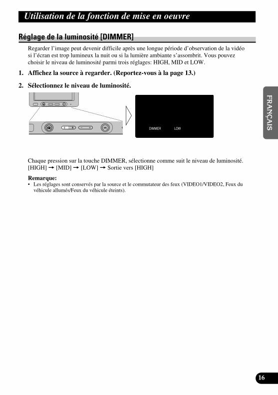
Réglage de la luminosité [DIMMER]Regarder l’image peut devenir difficile après une longue période d’observation de la vidéosi l’écran est trop lumineux la nuit ou si la lumière ambiante s’assombrit. Vous pouvezchoisir le niveau de luminosité parmi trois réglages: HIGH, MID et LOW.
1. Affichez la source à regarder. (Reportez-vous à la page 13.)
2. Sélectionnez le niveau de luminosité.
Chaque pression sur la touche DIMMER, sélectionne comme suit le niveau de luminosité.[HIGH] = [MID] = [LOW] = Sortie vers [HIGH]
Remarque:• Les réglages sont conservés par la source et le commutateur des feux (VIDEO1/VIDEO2, Feux du
véhicule allumés/Feux du véhicule éteints).
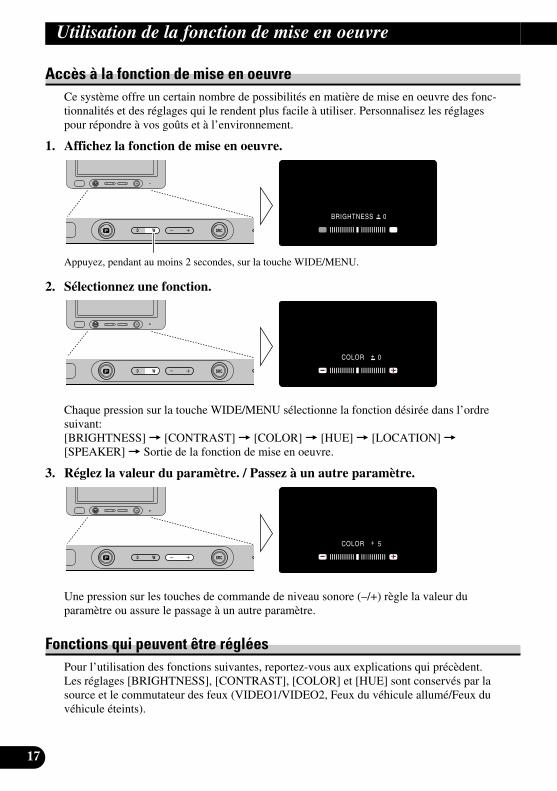
Accès à la fonction de mise en oeuvreCe système offre un certain nombre de possibilités en matière de mise en oeuvre des fonc-tionnalités et des réglages qui le rendent plus facile à utiliser. Personnalisez les réglagespour répondre à vos goûts et à l’environnement.
1. Affichez la fonction de mise en oeuvre.
Appuyez, pendant au moins 2 secondes, sur la touche WIDE/MENU.
2. Sélectionnez une fonction.
Chaque pression sur la touche WIDE/MENU sélectionne la fonction désirée dans l’ordresuivant:[BRIGHTNESS] = [CONTRAST] = [COLOR] = [HUE] = [LOCATION] =[SPEAKER] = Sortie de la fonction de mise en oeuvre.
3. Réglez la valeur du paramètre. / Passez à un autre paramètre.
Une pression sur les touches de commande de niveau sonore (–/+) règle la valeur duparamètre ou assure le passage à un autre paramètre.
Fonctions qui peuvent être régléesPour l’utilisation des fonctions suivantes, reportez-vous aux explications qui précèdent.Les réglages [BRIGHTNESS], [CONTRAST], [COLOR] et [HUE] sont conservés par lasource et le commutateur des feux (VIDEO1/VIDEO2, Feux du véhicule allumé/Feux duvéhicule éteints).
17
Utilisation de la fonction de mise en oeuvre

18
EN
GLIS
HFR
AN
ÇA
ISD
EU
TS
CH
FR
AN
ÇA
ISIT
ALIA
NO
NED
ER
LAN
DS
Luminosité [BRIGHTNESS]Vous pouvez agir de manière que le noir semble plus ou moins sombre (-24 à +24).
Contraste [CONTRAST]Vous pouvez agir de manière que l’écart entre le noir et le blanc (assombri) soit plus oumoins étendu (-24 à +24).
Couleur [COLOR]Vous pouvez agir de manière que les couleurs semblent plus ou moins sombres (-24 à +24).
Tonalité [HUE]Vous pouvez agir sur le rouge et le vert de l’image (-24 à +24).
Emplacement [LOCATION]Quand vous utilisez l’écran pour la première fois après son achat, indiquez l’emplacementde montage.[FRONT]: Cet appareil est installé sur le tableau de bord ou en un autre emplacement telque le conducteur puisse voir l’écran.[REAR]: Cet appareil est installé en un emplacement tel que les passagers arrière puissentregarder l’image (un emplacement où le conducteur ne peut pas voir l’écran).
Remarque:• Lorsque [LOCATION] est réglé sur [FRONT], la vidéo ne peut pas être regardée pendant que le
véhicule se déplace. De plus, la page de fonction de mise en oeuvre ne peut pas être affichée pen-dant que le véhicule se déplace. ([ATTENTION] s’affiche quand le véhicule se déplace.)Garez le véhicule dans un endroit sûr, serrez le frein de stationnement et attendez que [ATTENTION] s’éteigne pour commencer l’utilisation.
Haut-parleur [SPEAKER]Vous pouvez sélectionnez [ON] ou [OFF] comme réglage pour le signal sonore provenantdu haut-parleur intégré.

19
ATTENTION• Si de l’humidité ou un corps étranger devait s’infiltrer dans l’unité, mettez-la
immédiatement hors tension (OFF) et consultez votre concessionnaire ou uncentre de service PIONEER agréé. Utiliser l’unité sans vérification pourraitprovoquer un incendie, une électrocution ou d’autres problèmes.
• Si vous constatez une fumée, un bruit ou une odeur étrange ou toute autreanomalie liée à l’écran, mettez-le immédiatement hors tension (OFF) et con-sultez votre concessionnaire ou un centre de service PIONEER agréé.Utiliser l’unité sans vérification pourrait provoquer une panne du système.
• Ne déposez pas le couvercle arrière de l’écran car la présence de composantssous haute tension pourrait provoquer une électrocution. Confiez tout travaild’inspection, de réglage ou de réparation à un concessionnaire ou à un centrede service PIONEER agréé.
Maniement de l’écran• Lorsque l’écran n’est pas utilisé, ne le laissez pas dans la lumière directe du soleil ni
exposé à des températures extrêmes.• Utilisez l’écran en tenant compte des plages de température suivantes.
Plage de température d’utilisation: de –10 à +50 °C [de +14 à 122 °F]Plage de température de rangement: de –20 à +80 °C [de –4 à 176 °F]Si la température dépasse les maxima et minima de la plage indiquée, l’écran risque dene pas fonctionner correctement.
• L’écran Cristaux de cet article a été traité pour améliorer sa lecture dans une voiture.N’appuyez pas fortement sur le verre car il pourrait se briser.
• Pour éviter de le griffer ou de le salir, ne touchez pas le verre de l’écran Cristaux.
Utilisation convenable de l’écran

20
EN
GLIS
HFR
AN
ÇA
ISD
EU
TS
CH
FR
AN
ÇA
ISIT
ALIA
NO
NED
ER
LAN
DS
A propos de l’écran à cristaux liquides (LCD)• Si l’écran est près de la bouche d’un climatiseur d’air quand il est ouvert, assurez-vous
que l’air du climatiseur ne souffle pas dessus. La chaleur du chauffage peut romprel’écran à cristaux liquides et l’air frais du refroidisseur peut entraîner la formation d’hu-midité à l’intérieur, ce qui peut avoir pour effet d’endommager l’écran. Par ailleurs, sil’écran est refroidi par le refroidisseur, l’écran peut devenir sombre, ou bien la durée devie du petit tube fluorescent utilisé à l’intérieur de l’écran peut être réduite.
• De petits points noirs ou des points blancs (points lumineux) peuvent apparaître surl’écran Cristaux du fait des caractéristiques de ce genre d’écran, mais ils ne constituenten rien un problème pour l’affichage.
• A basse température, l’écran Cristaux peut rester foncé pendant quelques instants aprèsla mise sous tension.
• La lecture de l’écran peut s’avérer difficile s’il est exposé en plein soleil.
Entretien de l’écran• Coupez l’alimentation électrique de l’écran Cristaux avant d’en enlever la poussière ou
de le nettoyer; utilisez pour cela un linge doux et sec.• Veillez à ne pas griffer la surface de l’écran lors de son nettoyage. N’utilisez pas de
détergents chimiques abrasifs à cette fin.• N’utilisez pas de chiffon humide pour nettoyer l’écran, ni de solvants organiques comme
l’essence, ni de diluants.
A propos du petit tube fluorescent• Un petit tube fluorescent est incorporé à l’affichage pour éclairer l’écran Cristaux.
* La lampe fluorescente s’use et sa durée de vie est limitée.* En fonction des conditions d’utilisation, ce tube fluorescent doit durer environ 10.000
heures. (Notez qu’une utilisation par basse température réduit la durée de service dutube fluorescent.)
* Lorsque le tube fluorescent atteint la fin de sa vie utile, l’écran s’assombrit et lesimages n’y sont plus visibles. Dans ce cas, consultez votre concessionnaire ou uncentre de service PIONEER agréé.

21
Branchement du système
ATTENTION• PIONEER ne vous recommande pas d’installer ou d’entretenir vous-même
cet écran, car ces travaux peuvent présenter un risque d’électrocution oud’autres dangers. Confiez tous les travaux d’installation et d’entretien devotre écran au personnel de service Pioneer agréé.
• Immobilisez toutes les câblages avec des serre-fils ou du ruban isolant. Nelaissez aucun conducteur à nu.
• Ne forez pas un orifice vers le compartiment du moteur afin de raccorder lefil jaune de l’appareil sur la batterie du véhicule car les vibrations du moteurpourraient à la longue abîmer l’isolation du fil au point de passage entrel’habitable et le compartiment du moteur. Veillez tout particulièrement àbien immobiliser le fil à ce point.
• Une situation très dangereuse pourrait se présenter si le fil de l’écran devaits’enrouler autour de la colonne de direction ou du levier des vitesses. Veillezà installer l’écran de telle sorte que rien ne fasse obstacle à la conduite.
• Assurez-vous que les câblages ne font pas obstacle aux pièces mobiles duvéhicule, telles que le levier des vitesses, le frein à main ou le mécanisme decoulissement des sièges.
• Ne court-circuitez pas les fils car le circuit de protection ne fonctionneraitplus correctement.
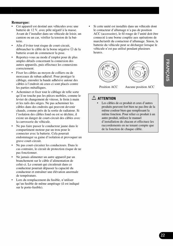
22
EN
GLIS
HFR
AN
ÇA
ISD
EU
TS
CH
FR
AN
ÇA
ISIT
ALIA
NO
NED
ER
LAN
DS
Remarque:• Cet appareil est destiné aux véhicules avec une
batterie de 12 V, avec pôle négatif à la masse.Avant de l’installer dans un véhicule de loisir, uncamion ou un car, vérifier la tension de la bat-terie.
• Afin d’éviter tout risque de court-circuit,débrancher le câble de la borne négative ≠ de labatterie avant de commencer la pose.
• Reportez-vous au mode d’emploi pour de plusamples détails concernant la connexion desautres appareils, puis effectuez les connexionscorrectement.
• Fixer les câbles au moyen de colliers ou demorceaux de ruban adhésif. Pour protéger lecâblage, enrouler la bande adhésive autour descâbles à l’endroit où ceux-ci sont placés contreles parties métalliques.
• Acheminer et fixer tout le câblage de telle sortequ’il ne touche pas les pièces mobiles, comme lelevier de changement de vitesse, le frein à mainet les rails des sièges. Ne pas acheminer lescâbles dans des endroits qui peuvent devenirchauds, comme près de la sortie de radiateur. Sil’isolation des câbles fond ou est se déchire, ilexiste un danger de court-circuit des câbles avecla carrosserie du véhicule.
• Ne pas faire passer le conducteur jaune dans lecompartiment moteur par un trou pour le connecter avec la batterie. Cela pourrait endommager sa gaine d’isolation et provoquer ungrave court-circuit.
• Ne pas court-circuiter les conducteurs. Dans lecas contraire, le circuit de protection risque de nepas fonctionner.
• Ne jamais alimenter un autre appareil par unbranchement sur le câble d’alimentation de celui-ci. Le courant qui circulerait dans ce conducteur pourrait dépasser la capacité du conducteur et entraîner une élévation anormalede température.
• Lors du remplacement du fusible, n’utiliserqu’un fusible de même ampérage (il est indiquésur le porte-fusible).
• Si cette unité est installée dans un véhicule dontle contacteur d’allumage n’a pas de positionACC (accessoire), le fil rouge de l’unité doit êtreconnecté à une borne couplée aux opérations demarche/arrêt du contacteur d’allumage. Sinon, labatterie du véhicule peut se décharger lorsque levéhicule n’est pas utilisé pendant plusieursheures.
ATTENTION• Les câbles de ce produit et ceux d’autres
produits peuvent fort bien ne pas être de lamême couleur bien que remplissant lamême fonction. Pour relier ce produit à unautre produit, utilisez le manueld’installation de chacun et effectuez lesraccordements en ne tenant compte quede la fonction de chaque câble.
Aucune position ACCPosition ACC
ONS
TA
R
T
OFF
ACCON
STA
R
T
OFF

23
Branchement du système
Noms et fonctions des prises de raccordement
7 Appareil déporté
1 Entrée vidéo Cinch (RCA)VIDEO1 (jaune)Elle reçoit la vidéo provenant d’unmagnétoscope, d’un lecteur de DVD oud’un autre équipement audiovisuel.
2 Entrée audio Cinch (RCA)VIDEO1 (blanc, rouge)Elle reçoit l’audio stéréophoniqueprovenant d’un magnétoscope, d’unlecteur de DVD ou d’un autreéquipement audiovisuel.
3 Entrée vidéo Cinch (RCA)VIDEO2 (jaune)Elle reçoit la vidéo provenant d’unmagnétoscope, d’un lecteur de DVD oud’un autre équipement audiovisuel.
4 Entrée audio Cinch (RCA)VIDEO2 (blanc, rouge)Elle reçoit l’audio stéréophoniqueprovenant d’un magnétoscope, d’unlecteur de DVD ou d’un autreéquipement audiovisuel.
5 AlimentationElle reçoit le câble d’alimentation fourni.
6 Sortie de l’écran (blanc)Elle connecte à l’écran.
7 Sortie vidéo Cinch (RCA) (jaune)Elle connecte à un autre équipementaudiovisuel. La vidéo sélectionnée àl’aide de cet écran est appliquée surcette borne.
8 Sortie audio Cinch (RCA) (blanc,rouge)Elle connecte à un autre équipementaudiovisuel. L’audio sélectionnée à l’aidede cet écran est appliquée sur ces bornes.
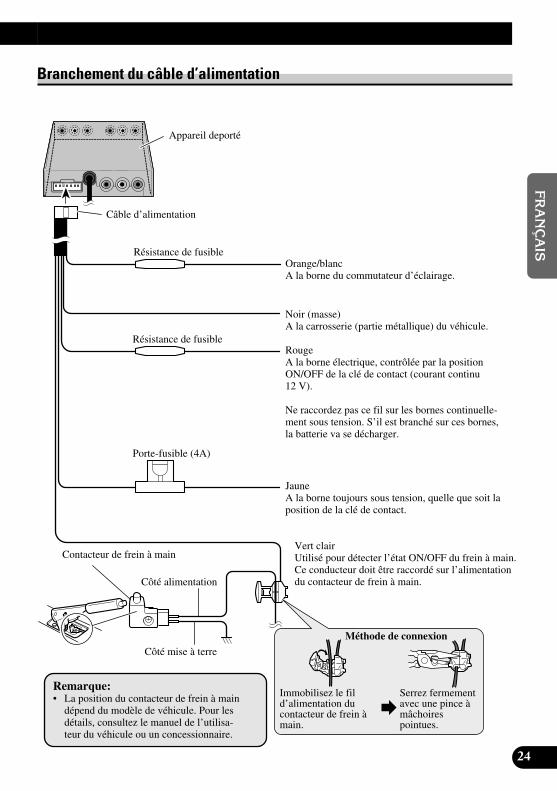
24
EN
GLIS
HFR
AN
ÇA
ISD
EU
TS
CH
FR
AN
ÇA
ISIT
ALIA
NO
NED
ER
LAN
DS
Câble d’alimentation
Résistance de fusible
Vert clairUtilisé pour détecter l’état ON/OFF du frein à main.Ce conducteur doit être raccordé sur l’alimentationdu contacteur de frein à main.
Contacteur de frein à main
Côté alimentation
Côté mise à terre
Appareil deporté
Orange/blancA la borne du commutateur d’éclairage.
JauneA la borne toujours sous tension, quelle que soit laposition de la clé de contact.
Méthode de connexion
Immobilisez le fild’alimentation ducontacteur de frein àmain.
Serrez fermementavec une pince àmâchoirespointues.
RougeA la borne électrique, contrôlée par la positionON/OFF de la clé de contact (courant continu 12 V).
Ne raccordez pas ce fil sur les bornes continuelle-ment sous tension. S’il est branché sur ces bornes,la batterie va se décharger.
Noir (masse)A la carrosserie (partie métallique) du véhicule.
Remarque:• La position du contacteur de frein à main
dépend du modèle de véhicule. Pour lesdétails, consultez le manuel de l’utilisa-teur du véhicule ou un concessionnaire.
Branchement du câble d’alimentation
Résistance de fusible
Porte-fusible (4A)

25
Branchement du système
Schéma de connexion (entrée VIDEO)
Remarque:• Ce système possède des réglages [FRONT/REAR] d’emplacement de montage [LOCATION].
N’oubliez pas d’effectuer ces réglages après que le système a été installé. (Reportez-vous à lapage 18.)
Blanc
Composant vidéoportatif disponibledans le commerceavec sortie Cinch(RCA)
Vers la sortie vidéo
Vers la sortie audio
Entrée VIDEO2
Entrée VIDEO1
Appareil déporté
3 m
Entrée audio Cinch (RCA)VIDEO1 (blanc, rouge)
Entrée vidéo Cinch (RCA)VIDEO1 (jaune)
Câbles Cinch (RCA) disponibles dans le commerce(vendus séparément)
Unité écran

26
EN
GLIS
HFR
AN
ÇA
ISD
EU
TS
CH
FR
AN
ÇA
ISIT
ALIA
NO
NED
ER
LAN
DS
Connexion à la sortie audio et vidéo Cinch (RCA)
Câble d’alimentation(Reportez-vous à lapage 22.)
Appareil déporté
Sortie vidéo Cinch (RCA) (jaune)Sortie audio Cinch (RCA) (blanc, rouge)
Câbles Cinch (RCA) disponibles dansle commerce (vendus séparément)
Vers l’entrée audio (R)
Vers l’entrée audio (L)
Vers l’entrée vidéo
Second écran, platinevidéo, etc.

27
Installation
ATTENTION• Pour les instructions de montage de l’écran, consultez votre revendeur.• Les lois de certains gouvernements peuvent interdire ou limiter l’installation
et l’emploi de ce système dans les voitures. Conformez-vous à toutes les loiset réglementations en vigueur sur l’installation, l’utilisation et le fonction-nement de l’écran.
• N’installez pas l’écran à un endroit où (i) il réduirait le champ de vision duconducteur, (ii) il gênerait le fonctionnement des systèmes du véhicule ou desdispositifs de sécurité, notamment les airbags, ou (iii) il diminuerait la sécu-rité de la conduite.
• PIONEER ne vous recommande pas d’installer ou d’entretenir vous-mêmecet écran, car ces travaux peuvent présenter un risque d’électrocution oud’autres dangers. Confiez tous les travaux d’installation et d’entretien devotre écran au personnel de service PIONEER agréé.
• Installez l’écran entre le siège du conducteur et celui du passager avant demanière qu’il ne soit cogné ni par l’un ni par l’autre en cas de freinagebrusque.
• N’installez pas l’écran à un endroit où il gênerait le déploiement total del’airbag.
• N’installez pas l’écran à un endroit où il gênerait les performances des dis-positifs du véhicule, y compris les airbags et les appui-tête.
• Avant d’y forer des trous, assurez-vous que rien ne se trouve derrière laplanche de bord ou une cloison. Veillez à ne pas endommager les canalisa-tions de carburant, circuits de freinage ou câbles d’alimentation.
• A l’emploi de vis, faites attention à un contact éventuel avec un conducteurélectrique. Des vibrations pourraient endommager les fils et provoquer uncourt-circuit ou d’autres dégâts sur le véhicule.
• Une situation très dangereuse pourrait se présenter si le fil de l’écran devaits’enrouler autour de la colonne de direction ou du levier des vitesses. Veillezà installer l’écran de telle sorte que rien ne fasse obstacle à la conduite.
• Assurez-vous qu’aucun fil ou conducteur n’est coincé dans une porte ou lemécanisme de coulissement d’un siège, car ceci pourrait provoquer un court-circuit.

28
EN
GLIS
HFR
AN
ÇA
ISD
EU
TS
CH
FR
AN
ÇA
ISIT
ALIA
NO
NED
ER
LAN
DS
• Si cet appareil est installé dans un endroit où le conducteur peut le voir, ilFAUT toujours régler le paramètre [LOCATION] sur [FRONT]. Sinon, desimages risquent de perturber le conducteur s’il y a une possibilité qu’il lesvoit pendant qu’il conduit.Si cet appareil est installé à un endroit où le conducteur ne peut pas le voir, ilest possible de choisir le paramètre de position [REAR].L’utilisation de cet appareil est soumise aux lois des gouvernements en ce quiconcerne son emplacement et son utilisation.PIONEER ne saurait être tenue responsable en cas d’anomalie, de dommage,ou de perte résultant de l’utilisation de l’appareil dans des conditions incor-rectes ou en violation des lois du gouvernement.
• Pour garantir une installation correcte, utilisez les pièces fournies de lamanière indiquée. Si une pièce autre que celles fournies est utilisée, elle peutendommager les pièces internes de l’appareil, ou elle peut se desserrer etl’appareil peut tomber.
Si l’écran et installé à l’avant
• Pour garantir une conduite sûre, veillez à installer l’écran dans un endroitqui réponde aux conditions suivantes.* Un endroit où il ne restreint pas la visibilité du conducteur ni ne gêne la
conduite sûre du véhicule.* Un endroit où l’avant de la voiture est dans le champ de vision du conduc-
teur quand il regarde l’écran.* Un endroit où il ne fait pas saillie au-dessus de l’avant du capot quand il
est vu par le conducteur.
Avant l’installation et la fixation• Effectuez d’abord des connexions temporaires afin de vérifier si l’unité et le système
fonctionnent correctement.• Appuyez sur le bouton RESET avec la pointe d’un stylo à bille ou d’un objet similaire
lorsqu’une connexion est terminée.
Avant d’employer le ruban adhésif• Afin de fixer le ruban adhésif, assurez-vous que l’endroit n’est ni humide ni souillé par
de la poussière ou de l’huile, etc.
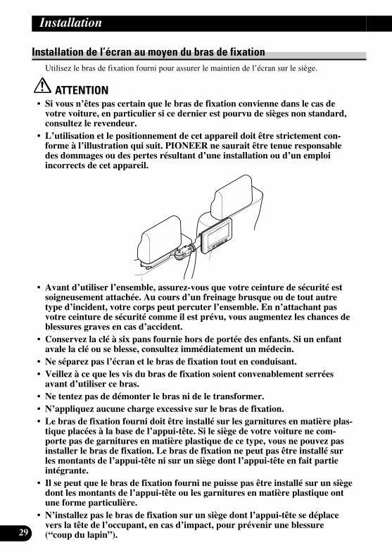
29
Installation de l’écran au moyen du bras de fixationUtilisez le bras de fixation fourni pour assurer le maintien de l’écran sur le siège.
ATTENTION• Si vous n’êtes pas certain que le bras de fixation convienne dans le cas de
votre voiture, en particulier si ce dernier est pourvu de sièges non standard,consultez le revendeur.
• L’utilisation et le positionnement de cet appareil doit être strictement con-forme à l’illustration qui suit. PIONEER ne saurait être tenue responsabledes dommages ou des pertes résultant d’une installation ou d’un emploiincorrects de cet appareil.
• Avant d’utiliser l’ensemble, assurez-vous que votre ceinture de sécurité estsoigneusement attachée. Au cours d’un freinage brusque ou de tout autretype d’incident, votre corps peut percuter l’ensemble. En n’attachant pasvotre ceinture de sécurité comme il est prévu, vous augmentez les chances deblessures graves en cas d’accident.
• Conservez la clé à six pans fournie hors de portée des enfants. Si un enfantavale la clé ou se blesse, consultez immédiatement un médecin.
• Ne séparez pas l’écran et le bras de fixation tout en conduisant.• Veillez à ce que les vis du bras de fixation soient convenablement serrées
avant d’utiliser ce bras.• Ne tentez pas de démonter le bras ni de le transformer.• N’appliquez aucune charge excessive sur le bras de fixation.• Le bras de fixation fourni doit être installé sur les garnitures en matière plas-
tique placées à la base de l’appui-tête. Si le siège de votre voiture ne com-porte pas de garnitures en matière plastique de ce type, vous ne pouvez pasinstaller le bras de fixation. Le bras de fixation ne peut pas être installé surles montants de l’appui-tête ni sur un siège dont l’appui-tête en fait partieintégrante.
• Il se peut que le bras de fixation fourni ne puisse pas être installé sur un siègedont les montants de l’appui-tête ou les garnitures en matière plastique ontune forme particulière.
• N’installez pas le bras de fixation sur un siège dont l’appui-tête se déplacevers la tête de l’occupant, en cas d’impact, pour prévenir une blessure(“coup du lapin”).
Installation

1. Appuyez sur le bouton de libération, faites glisser l’appui-tête vers le haut etretirez-le.
Remarque:• Il se peut que le bras de fixation fourni ne puisse pas être installé sur un siège qui est muni d’un
bouton de libération ne faisant pas face à l’extérieur.
2. Réglez les guides des montants de manière que les montants traversent lebras de fixation.Choisissez les perçages qui conviennent aux montants puis réglez la distance entre lesguides des montants en fonction de l’écart qui sépare les montants.
77 Retrait et pose des guides des montants.
Remarque:• L’écart convenable entre les montants est compris entre 120 et 190 mm. 30
EN
GLIS
HFR
AN
ÇA
ISD
EU
TS
CH
FR
AN
ÇA
ISIT
ALIA
NO
NED
ER
LAN
DS
Appui-tête
Montant
Garnitures
Exemples: Positions des guides des montants
Choisissez un perçage en fonction du diamètre du montant.
Réglez la position des guides des montants en fonction de l’écart.
Pour retirer les guides desmontants, exercez une pousséesur la partie inférieure du brasde fixation.
Vous pouvez faire glisserle guide latéral gauchepour effectuer le réglage.
Verrouiller les guides des montants dans leur position.
Vous pouvez changer ladirection du guide latéralgauche.
Vous ne pouvez paschanger la direction duguide latéral droit.
Modèle le plus étroit (120 mm)Modèle le plus large (190 mm)
Le guide latéral droitne peut être placé qu’àl’une des extrémités.

31
3. Installez le bras de fixation sur les garnitures en matière plastique des mon-tants de l’appui-tête.
Si le bras de fixation n’est pas solidement maintenu en raison de la forme ou du matériau dusiège, utilisez les entretoises caoutchoutées pour effectuer l’installation du bras de fixation.
4. Engagez les montants de l’appui-tête dans les perçages des guides des mon-tants puis replacez l’appui-tête dans sa position d’origine.
5. Ouvrez le bras puis réglez la position et l’angle. Choisissez l’emplacementd’installation de l’écran.
Installation
Faites glisser le bras de fixation de ladroite vers la gauche tout en exerçantune pression.
Engagez les supports en U dans l’espace entre les garnitures et lasurface du siège.
Garnitures Support en U
Retirez les protections posées sur les entretois-es puis fixez les entretoises sur la matière plas-tique du bras de fixation.
Pour pousser sur le boutonde libération, introduisezun doigt dans le perçage.
Abaissez l’appui-tête pour qu’il reprennesa position d’origine.
Retirez la clé à six pans du bras de fixationafin de pouvoir l’utiliser ultérieurement.
Tournez la tête du bras jusqu’à ceque le bouton soit dirigé vers le bas.
Tournez latête du bras.
Tournez le bouton dansle sens contraire desaiguilles d’une montre.
Ouvrez le brascomplètement.
N’utilisez pas l’ensemble si le brasn’est pas complètement ouvert.

6. Installez l’écran sur le bras.
Utilisez la clé à six pans fournie pour serrer la vis une fois le réglage effectué. Si, aprèsavoir serré la vis, vous avez l’impression qu’il y a encore du jeu entre l’écran et le bras,tirez sur le levier de libération et retirer l’écran puis serrez encore plus la vis au moyen dela clé à six pans.
7. Placez le cache sur le bras.
32
EN
GLIS
HFR
AN
ÇA
ISD
EU
TS
CH
FR
AN
ÇA
ISIT
ALIA
NO
NED
ER
LAN
DS
Desserrez ces vis àl’aide de la clé à sixpans pour tourner lebras de fixation.
Écran
Pour assurer le maintien del’écran, serrez la vis invisi-ble en vous servant de la cléà six pans que vous avezengagée dans ce perçage.
Serrez la vis jusqu’à ce quele bras soit immobilisé.
Posez le cache sur lebras.

33
Installation
Installation de appareil déporté
Précautions d’installation• N’installez pas cet appareil dans des emplacements tels que ceux indiqués ci-dessous, à cause des
risques de dysfonctionnements dus à une température ou une humidité élevées:* le tableau de bord ou la plage arrière où il est exposé directement aux rayons du soleil.* près des grilles de sortie du chauffage.* près des portes ou autres ouvertures, où il risque d’être exposé à la pluie.
• Si vous l’installez sous le siège avant, vérifiez qu’il n’entrave pas le déplacement du siège vers l’avant ou vers l’arrière.
• Il est possible de l’installer directement sur le tapis si l’velcro dur y adhère correctement. Dans cecas, n’utilisez pas l’velcro souple.
Montage de appareil déporté
Collez la bande Velcro rigide (fournie) sur le fond de l’appareil déporté et la bande Velcrosouple (fournie) à l’endroit où vous voulez l’installer.aa Appareil déporté
Bande velcro (dur)
Bande velcro (souple)
Tapis de lavoiture

34
EN
GLIS
HFR
AN
ÇA
ISD
EU
TS
CH
FR
AN
ÇA
ISIT
ALIA
NO
NED
ER
LAN
DS
Caractéristiques techniques
GénéralitésAlimentation ........................................................................ 14,4 V CC (de 10,8 à 15,1 V possibles)Mise à la masse .................................................................... Pôle négatifConsommation maximale .................................................... 2,0 A
Unité écranTaille de l’écran; rapport de la largeur à la hauteur ............ 6,5 pouces; 16:9
(Surface réelle d’affichage: 143,75 × 76 mm)Pixels .................................................................................. 336.960 (234 × 1.440)Type .................................................................................... Matrice active TFT, type à transmissionSystèmes couleur ................................................................ NTSCPlage de température d’utilisation ...................................... De –10 à +50 °C [de +14 à 122 °F]Plage de température de rangement .................................... De –20 à +80 °C [de –4 à 176 °F]Haut-parleur intégré ............................................................ ø 36 mmDimensions .......................................................................... 188 (L) × 114 (H) × 32 (P) mmPoids .................................................................................... 430 g
Appareil déportéNiveau de sortie vidéo externe ............................................ 1 Vp-p/75 ΩNiveau d’entrée vidéo externe.............................................. 1 V/22 kΩImpédance de sortie maximale ............................................ 1 Vp-p/75 ΩNiveau maximum de sortie audio externe .......................... 1 V/1 kΩDimensions .......................................................................... 104 (L) × 85 (H) × 26 (P) mmPoids .................................................................................... 570 g
Remarque:• Les spécifications et l’aspect sont sujets à modifications sans avis préalable. Sur des points de détail, il se
peut que les articles réels soient différents de ceux illustrés dans cette brochure.


Published by Pioneer Corporation.Copyright © 2003 by Pioneer Corporation.All rights reserved.
Publication de Pioneer Corporation.Copyright © 2003 Pioneer Corporation.Tous droits de reproduction et de traductionréservés.
Printed in JapanImprimé au Japon
<CRD3749-B> UC<KKYNF/03B00001>
PIONEER CORPORATION4-1, MEGURO 1-CHOME, MEGURO-KU, TOKYO 153-8654, JAPAN
PIONEER ELECTRONICS (USA) INC.P.O. Box 1540, Long Beach, California 90801-1540, U.S.A.TEL: (800) 421-1404
PIONEER EUROPE NVHaven 1087, Keetberglaan 1, B-9120 Melsele, BelgiumTEL: (0) 3/570.05.11
PIONEER ELECTRONICS ASIACENTRE PTE. LTD.253 Alexandra Road, #04-01, Singapore 159936TEL: 65-6472-1111
PIONEER ELECTRONICS AUSTRALIA PTY. LTD.178-184 Boundary Road, Braeside, Victoria 3195, AustraliaTEL: (03) 9586-6300
PIONEER ELECTRONICS OF CANADA, INC.300 Allstate Parkway, Markham, Ontario L3R OP2, CanadaTEL: (905) 479-4411
PIONEER ELECTRONICS DE MEXICO, S.A. de C.V.Blvd.Manuel Avila Camacho 138 10 pisoCol.Lomas de Chapultepec, Mexico, D.F. 11000TEL: 55-9178-4270


![Datsun GO Datsun GO+ · 6 Quick Reference Guide Quick Reference Guide 7 TUMBLE SEAT OPERATION [IF EQUIPPED] PULL Fig. 1 Fig. 2 Fig. 3 REAR TUMBLE SEAT USAGE Rear seat tumble position](https://static.fdocuments.in/doc/165x107/5f6e750bed4b8c374617b5b2/datsun-go-datsun-go-6-quick-reference-guide-quick-reference-guide-7-tumble-seat.jpg)
