16575 F2097 LexCom Modena C-Bus Wall Switch … · LexCom Modena C-Bus Wall Switch Installation...
16
Transcript of 16575 F2097 LexCom Modena C-Bus Wall Switch … · LexCom Modena C-Bus Wall Switch Installation...


© Copyright PDL Electrical Solutions (PDL) 2008. All rights reserved. This material is copyright under Australian and international laws. Except as permitted under the relevant law, no part of this work may be reproduced by any process without prior written permission of and acknowledgement to PDL.
PDL is a registered trademark of Schnieder Electric New Zealand Holdings Ltd. LexCom Home is a registered trademark of Schneider Electric Aust Pty Ltd.
Encryption by QUALCOMM
Megger® is a registered trademark of AVO International (formerly the Biddle Co.), but the term is widely used for all similar tests regardless of manufacturer.
The information in this manual is provided in good faith. Whilst PDL has endeavoured to ensure the relevance and accuracy of the information, it assumes no responsibility for any loss incurred as a result of its use. PDL does not warrant that the information is fit for any particular purpose, nor does it endorse its use in applications which are critical to the health or life of any human being. PDL reserves the right to update the information at any time without notice.

LexCom Modena C-Bus Wall Switch Installation Instructions
3
Contents
1.0 Product Range 5
2.0 Important Notes 5
3.0 Description 5
4.0 Installation Considerations 6
5.0 Mounting Instructions 7
5.1 Switch Orientation 7
5.2 C-Clip Mounting 8
5.3 Wall Box Mounting 9
5.4 Installing the Cover Plate 10
5.5 Removing the Cover Plate 10
6.0 C-Bus Network Connection 11
7.0 C-Bus Power Requirements 12
8.0 Megger Testing 12
9.0 Programming Requirements 12
10.0 Electrical Specifications 13
11.0 Mechanical Specifications 14
12.0 Standards Complied 15
13.0 Warranty 15

LexCom Modena C-Bus Wall Switch Installation Instructions
4

LexCom Modena C-Bus Wall Switch Installation Instructions
5
1.0 Product Range
This document applies to the LexCom Modena C-Bus Wall Switch models listed below.
Catalogue Number Description
LHC882, WH Modena C-Bus Wall Switch, white, 2 button
LHC882, BK Modena C-Bus Wall Switch, black, 2 button
LHC884, WH Modena C-Bus Wall Switch, white, 4 button
LHC884, BK Modena C-Bus Wall Switch, black, 4 button
LHC886, WH Modena C-Bus Wall Switch, white, 6 button
LHC886, BK Modena C-Bus Wall Switch, black, 6 button
2.0 Important Notes
Do not connect mains to the Modena C-Bus Wall Switch units. The C-Bus network uses CAT-5 network cables.
The use of any software not provided by Clipsal Integrated Systems (CIS) in conjunction with the installation of this product may void any warranties applicable to the hardware.
3.0 Description
The LexCom Modena C-Bus Wall Switch Series is a high-end range of C-Bus input units. Units feature multiple buttons, scene management and learn mode capability.

LexCom Modena C-Bus Wall Switch Installation Instructions
6
4.0 Installation Considerations
It is important to select the right location to install LexCom Modena C-Bus Wall Switches. Some considerations are listed below:
• Provide easy access to the unit for switching lights and selecting scenes.
• Choose a location free of water, humidity, direct sunlight and heavy dust.
• Allow adequate ventilation.
• Do not cover the unit.
• Units are designed for indoor use only.
• Units may be mounted vertically or horizontally.
no wethands
no cleanerspray
nocoverage
no directsunshine
nodust

LexCom Modena C-Bus Wall Switch Installation Instructions
7
5.0 Mounting Instructions
LexCom Modena C-Bus Wall Switches suit standard 84 mm centre mounting accessories, such as the PDL 146C and 147. It is recommended that 147 wall boxes be earthed.
Mounting accessories must be fitted a minimum distance of 10 mm back from the finished surface of the wall. When mounting vertically, fit the grid plate to the wall with the release locks at the bottom.
The following installation methods are suggestions only. All units must be installed within the local electrical authority guidelines.
5.1 Switch Orientation
Figure 1 shows the rear and front orientations of a 6 button LexCom Modena C-Bus Wall Switch.
Figure 1. Rear and front views of a 6-button wall switch

LexCom Modena C-Bus Wall Switch Installation Instructions
8
5.2 C-Clip Mounting
For a plasterboard installation, LexCom Modena C-Bus Wall Switches can be mounted in a horizontal or vertical orientation. Be sure to install the front cover with the PDL logo in the position shown in Figure 2 and Figure 3.
Figure 2. C-Clip mounting in the horizontal orientation
Figure 3. C-Clip mounting in the vertical orientation

LexCom Modena C-Bus Wall Switch Installation Instructions
9
5.3 Wall Box Mounting
A Modena wall switch can be fitted to a wall box. This allows it to be easily mounted in a new or existing installation. A wall box may be fitted into suitably prepared masonry, or attached to a noggin fitted between studs in timber stud construction. Refer to the illustrations in Figure 4 and Figure 5.
Figure 4. Wall box mounting in the horizontal orientation
Figure 5. Wall box mounting in the vertical orientation

LexCom Modena C-Bus Wall Switch Installation Instructions
10
5.4 Installing the Cover Plate
1) Align cover plate over the buttons on the grid, with the PDL logo at the bottom left (horizontal mounting) or bottom right (vertical mounting).
2) With thumbs positioned over the release slots (Figure 6), press the cover plate onto the grid until it clips into place.
Figure 6. The release slots provide easy removal of the cover plate
5.5 Removing the Cover Plate
To remove a switch cover plate:
1) Insert the blade of a small flat head screwdriver into one of the release slots (Figure 6).
2) Lever the cover plate off the grid.

LexCom Modena C-Bus Wall Switch Installation Instructions
11
6.0 C-Bus Network Connection
Installation of a wall switch unit on the C-Bus network requires connection to the unshielded twisted pair C-Bus cable. Figure 7 identifies the connections required between the C-Bus Cat-5 cable and the wall switch unit. Terminal locations are shown in Figure 8. Connection should be made using Category 5 (Cat-5) data cable, Clipsal catalogue number 5005C305B.
Figure 7. C-Bus cable conductor assignments
C-Bus Connection Colour Modena C-Bus Connection
C-Bus Positive (+) blue yes C-Bus Negative (–) blue & white yes C-Bus Positive (+) orange yes C-Bus Negative (–) orange & white yes Remote ON green no Remote ON green & white no Remote OFF brown no Remote OFF brown & white no
Figure 8. Terminal Wiring
LexCom Modena C-Bus Wall Switch Installation Instructions
12
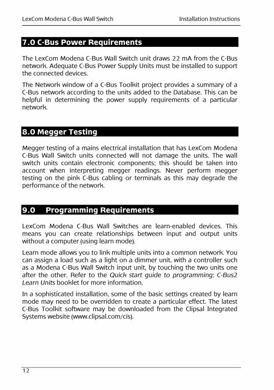
7.0 C-Bus Power Requirements
The LexCom Modena C-Bus Wall Switch unit draws 22 mA from the C-Bus network. Adequate C-Bus Power Supply Units must be installed to support the connected devices.
The Network window of a C-Bus Toolkit project provides a summary of a C-Bus network according to the units added to the Database. This can be helpful in determining the power supply requirements of a particular network.
8.0 Megger Testing
Megger testing of a mains electrical installation that has LexCom Modena C-Bus Wall Switch units connected will not damage the units. The wall switch units contain electronic components; this should be taken into account when interpreting megger readings. Never perform megger testing on the pink C-Bus cabling or terminals as this may degrade the performance of the network.
9.0 Programming Requirements
LexCom Modena C-Bus Wall Switches are learn-enabled devices. This means you can create relationships between input and output units without a computer (using learn mode).
Learn mode allows you to link multiple units into a common network. You can assign a load such as a light on a dimmer unit, with a controller such as a Modena C-Bus Wall Switch input unit, by touching the two units one after the other. Refer to the Quick start guide to programming: C-Bus2 Learn Units booklet for more information.
In a sophisticated installation, some of the basic settings created by learn mode may need to be overridden to create a particular effect. The latest C-Bus Toolkit software may be downloaded from the Clipsal Integrated Systems website (www.clipsal.com/cis).

LexCom Modena C-Bus Wall Switch Installation Instructions
13
10.0 Electrical Specifications
Parameter Description
C-Bus supply voltage 15 to 36 V DC, 22 mA for normal operation. Does not provide current to the C-Bus network
C-Bus AC input impedance
50 kΩ @ 1 kHz
Electrical isolation 3.75 kV RMS from C-Bus to mains (provided externally to LHC88x Series unit)
Maximum number of units on network
50
Control functions Load switching, dimming, timers, scene control
Status indicators User configurable orange and blue
Warm-up time 5 seconds
C-Bus connection One terminal block to accommodate 0.2 to 1.3 mm2 (24 to 16 AWG)
Operating temperature range
0 to 45 °C
Operating humidity range
10 to 90% RH

LexCom Modena C-Bus Wall Switch Installation Instructions
14
11.0 Mechanical Specifications
Parameter Description
Mounting Centres 84 mm
Dimensions (W x H x D) 124.2 × 84.0 × 15mm
Figure 9. Wall Switch Dimensions
LexCom Modena C-Bus Wall Switch Installation Instructions
15
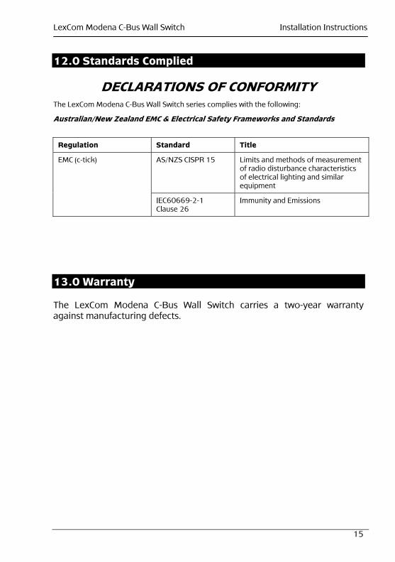
12.0 Standards Complied
DECLARATIONS OF CONFORMITY The LexCom Modena C-Bus Wall Switch series complies with the following:
Australian/New Zealand EMC & Electrical Safety Frameworks and Standards
13.0 Warranty
The LexCom Modena C-Bus Wall Switch carries a two-year warranty against manufacturing defects.
Regulation Standard Title
AS/NZS CISPR 15 Limits and methods of measurement of radio disturbance characteristics of electrical lighting and similar equipment
EMC (c-tick)
IEC60669-2-1 Clause 26
Immunity and Emissions