161833 LANTEK AXT Manual - IDEAL IND · 3 IDEAL INDUSTRIES STANDARD WARRANTY POLICY IDEAL...
37
OPERATION MANUAL LanTEK II/LanTEK III Alien Crosstalk Testing Accessory
Transcript of 161833 LANTEK AXT Manual - IDEAL IND · 3 IDEAL INDUSTRIES STANDARD WARRANTY POLICY IDEAL...
OPERATION MANUAL
LanTEK II/LanTEK III Alien Crosstalk Testing Accessory

C O P Y R I G H T N O T I C E
The information contained in this document is the property of IDEAL INDUSTRIES Ltd. and is supplied without liability for errors and omissions. No part of this document may be reproduced or used except as authorized by contract or other written permission from IDEAL INDUSTRIES Ltd. The copyright and all restrictions on reproduction and use apply to all media in which this information may be placed.
IDEAL INDUSTRIES Ltd. pursues a policy of continual product improvement and reserves the right to alter without notice the specification, design, price or conditions of supply of any product or service.
© IDEAL INDUSTRIES LTD. 2017
All rights reserved Publication ref: 161833 Issue 1 - 03/17
IDEAL INDUSTRIES LTD. Stokenchurch House Oxford Road Stokenchurch High Wycombe Buckinghamshire HP14 3SX UK www.idealnetworks.net

3
IDEAL INDUSTRIES STANDARD WARRANTY POLICY IDEAL INDUSTRIES warrant that all LANTEK Products manufactured or procured by IDEAL INDUSTRIES conform to IDEAL INDUSTRIES’ published specifications and are free from defects in materials and workmanship for a period of one (1) year from the date of delivery to the original Buyer, when used under normal operating conditions and within the service conditions for which they are designed. This warranty is not transferable and does not apply to used or demonstration products.
The obligation of IDEAL INDUSTRIES arising from a Warranty claim shall be limited to repairing, or at its option, replacing without charge, any assembly or component (except batteries and cable adapters), which in IDEAL INDUSTRIES’ sole opinion proves to be defective within the scope of the Warranty. In the event IDEAL INDUSTRIES is not able to modify, repair or replace nonconforming defective parts or components to a condition as warranted within a reasonable time after receipt thereof, Buyers shall receive credit in the amount of the original invoiced price of the product.
IDEAL INDUSTRIES must be notified in writing of the defect or nonconformity within the Warranty period and the affected Product returned to IDEAL INDUSTRIES’ factory, designated Service Provider, or Authorized Service Center within thirty (30) days after discovery of such defect or nonconformity. Buyer shall prepay shipping charges and insurance for Products returned to IDEAL INDUSTRIES or its designated Service Provider for warranty service. IDEAL INDUSTRIES or its designated Service Provider shall pay costs for return of Products to Buyer.
IDEAL INDUSTRIES shall have no responsibility for any defect or damage caused by improper storage, improper installation, unauthorized modification, misuse, neglect, inadequate maintenance, accident or for any Product which has been repaired or altered by anyone other than IDEAL INDUSTRIES or its authorized representative or not in accordance with instructions furnished by IDEAL INDUSTRIES.
The Warranty described above is Buyer’s sole and exclusive remedy and no other warranty, whether written or oral, expressed or implied by statute or course of dealing shall apply. IDEAL INDUSTRIES specifically disclaim the implied warranties of merchantability and fitness for a particular purpose. No statement, representation, agreement, or understanding, oral or written, made by an agent, distributor, or employee of IDEAL INDUSTRIES, which is not contained in the foregoing Warranty will be binding upon IDEAL INDUSTRIES, unless made in writing and executed by an authorized representative of IDEAL INDUSTRIES. Under no circumstances shall IDEAL INDUSTRIES be liable for any direct, indirect, special, incidental, or consequential damages, expenses, or losses, including loss of profits, based on contract, tort, or any other legal theory.

4
T A B L E O F C O N T E N T S
TABLE OF CONTENTS ............................................................ 2
LIST OF FIGURES ...................................................................... 5
INTRODUCTION ......................................................................... 6
CHOOSING LINKS TO TEST .................................................. 8
SAMPLE TESTING GUIDELINES .................................................. 8
AXT TESTING CONFIGURATION ........................................ 11
INITIAL TESTING .......................................................................... 11 LANTEK SETUP ......................................................................... 11
FIELD CALIBRATION ............................................................. 14
FIELD CALIBRATION ................................................................. 14
RUNNING AXT TESTS ............................................................. 15
Select Victim Link .......................................................... 15 Select Test Configuration ........................................... 16 Select Disturber Links ................................................... 17
VIEWING TEST RESULTS ...................................................... 21
VIEWING DATA ON LANTEK ................................................. 21
PRINTING AXT REPORTS .................................................... 24
INSTALLING THE SOFTWARE .................................................. 24 CREATING PROJECTS .............................................................. 26 IMPORTING TEST DATA ............................................................ 27 AXT VIEWER USER INTERFACE ............................................ 29 PRINTING REPORTS ................................................................... 31 CLOSING PROJECTS ................................................................. 32 COPYING PROJECTS ................................................................. 32
5
L I S T O F F I G U R E S
Figure 1: Link Selection: Top panel is correct; bottom panel is incorrect. 9 Figure 2: Correct Link Selection ..................................................... 9 Figure 3: Incorrect Link Selection ............................................... 10 Figure 4: Selecting Additional Disturbers ................................ 10 Figure 5: Type A Configuration ...................................................... 11 Figure 6: Type B Configuration ..................................................... 12 Figure 7: Type C Configuration ..................................................... 12 Figure 8: Field calibration setup .................................................. 14 Figure 9: Job List ................................................................................ 15 Figure 10: Test ID List ........................................................................ 15 Figure 11: Type A ................................................................................ 16 Figure 12: Type B ................................................................................ 16 Figure 13: Type C ................................................................................ 16 Figure 14: Disturber List ................................................................... 17 Figure 15: Test List .............................................................................. 17 Figure 16: Prompt to begin test .................................................... 17 Figure 17: Completed Disturber Tests ........................................ 18 Figure 18: Insignificant AXT ............................................................ 18 Figure 19: AXT Summary, Passed Test ...................................... 19 Figure 20: AXT Summary, Insignificant .................................... 19 Figure 21: Exit without saving ....................................................... 19 Figure 22: AXT Data Screen .......................................................... 19 Figure 23: AXT Plot Data ............................................................... 20 Figure 24: Standard Job List .......................................................... 21 Figure 25: AXT Summary Page ..................................................... 21 Figure 26: PS ANEXT Tabular Data ............................................ 22 Figure 27: PS ANEXT Plot Data .................................................... 22 Figure 28: PS AACR-F Tabular Data .......................................... 22 Figure 29: PS AACR-F Plot Data ................................................. 22 Figure 30: PS ANEXT Average Tabular Data ......................... 23 Figure 31: PS ANEXT Average Plot Data .................................. 23 Figure 32: PS AACR-F Average Summary Data .................... 23 Figure 33: PS AACR-F Plot Data .................................................. 23 Figure 34: Begin Installation ......................................................... 24 Figure 35: Confirm Installation .................................................... 24 Figure 36: Select installation path ............................................... 25 Figure 37: Complete installation .................................................. 25 Figure 38: File Menu ........................................................................ 26 Figure 39: New Project Info .......................................................... 26 Figure 40: Select AXT job from CF card .................................. 28 Figure 41: Source location of data to import .......................... 28 Figure 42: AXT Viewer User Interface ...................................... 29 Figure 43: Cursor Details – Left click over the chart .......... 30 Figure 44: Chart Options ............................................................... 30 Figure 45: Print menu ........................................................................ 31 Figure 46: Standard printed report ............................................. 31 Figure 47: Printing full-page graph ............................................. 31 Figure 48: Print window .................................................................. 32 Figure 49: Full-page graphical printout .................................... 32

6
INTRODUCTION Thank you for purchasing the Alien Crosstalk testing kit for your LANTEK cable certifier. This alien crosstalk testing kit allows the LANTEK to perform alien crosstalk (AXT) testing on TIA Category 6A, ISO Class EA or greater cabling to certify its ability to support 10GbE data without transmission errors that can be caused by high frequency energy radiated by neighboring links. Any LANTEK 6A, 7G, LanTEK II 500/1000 or LanTEK III 500/1000 can be used to perform AXT testing so long as the links were originally certified to at Cat6-TSB155, Cat6A or ISO-EA cabling standards.
The Alien Crosstalk testing kit includes two Dual-port AXT adapters, 12 AXT terminators, patch cords, this user manual. The latest version of LANTEK firmware and the IDEAL AXT Viewer software should be downloaded from the IDEAL Networks website at www.idealnetworks.net
Definitions
The following definitions are useful for understanding the terminology used when testing alien crosstalk in the field.
Alien Crosstalk: Interference between links that are routed near each other in a bundle. Generally alien crosstalk becomes worse as transmission frequencies become higher and is most notable above 300MHz. Differs from traditional crosstalk as Alien crosstalk is between cables while traditional crosstalk is between pairs within a single cable.
Disturbed (Victim): The cabling link that has energy induced upon it by neighboring links during alien crosstalk testing. The field tester measures the signal level present on the victim link while the disturber links are energized.
Disturber/Disturbing: The link to which a signal is applied when measuring alien crosstalk. The signal applied to this link will couple to other links in the bundle.
IEC: International Electrotechnical Commission. An international standards committee that is often responsible for defining technical procedures. In regards to alien crosstalk testing, the IEC creates the technical definitions of how the field-testing be performed as well as the pass/fail of limits of each test. The IEC does not write cabling standards and therefore does not determine if alien crosstalk testing is required, only how it is done should the test be required. The TIA and ISO write field-testing specifications that determine when and if alien crosstalk testing is required.
Insignificant: Term used to describe alien crosstalk measurements that are low enough to not disrupt data at 10Gb/s rates. The IEC standard for alien crosstalk specifies that measurements of 90dB or less between 100 and 250MHz are deemed insignificant. The standard does not require insignificant data to be reported, however LANTEK will still report data to 100dB between 1 and 500MHz, beyond the requirements of the IEC.
Power Sum: A mathematical process to calculate the combined effects of several disturber links onto a singe victim link when making alien crosstalk measurements. All reported values when making alien crosstalk measurements are power sum calculations as the raw data is not useful in determining the net effect of alien crosstalk in a link bundle except when making decisions about insignificant AXT conditions.

7
PS AACR-F: Power Sum Attenuation to Alien Crosstalk Ratio, Far-end. Measurement of the alien crosstalk ratio, corrected for the length of the link when the disturber link is stimulated from the near end of the link and the victim link is measured from the far end of the link. This test is performed in both directions; therefore an “DH” or “RH” will be appended to the P AACR-F on the reports to indicate from which direction the test data applies.
PS ANEXT: Power Sum Alien Near End Crosstalk. Measurement of alien crosstalk when the disturber link is stimulated at the same side of the link where the victim link is measured. This test is run from both sides of the link and results in two sets of data. This test is performed in both directions; therefore an “NE” or “FE” will be appended to the P ANEXT on the reports to indicate from which direction the test data applies.
Sample Testing: Method of performing alien crosstalk tests that uses statistical sampling to minimize the time required to perform field-testing. Testing a single victim requires a minimum of six sets of tests from six disturber links. Since performing a 100% test of all the links in an installation can take hundreds of additional hours, sample testing is an accepted method of alien crosstalk certification.
Terminator: A passive device that presents a 100-ohm differential termination to a link under test. Terminators can be used with the LANTEK when performing Method A testing to speed up PS-ANEXT testing by terminating 12 links at the far end during single person testing.
TSB-155: Technical Service Bulletin #155. TSB’s are addenda to TIA standards that define optional specifications or procedures, often for field-testing. TSB-155 defines the requirements for testing Category 6 cabling to support 10GbE data rates. While Category 6 cabling was not designed to support 10GbE many vendor’s systems provide sufficient headroom to be driven at 500MHz (versus the Cat6 specification of 250MHz) over short distances. TSB-155 is an optional test of Category 6 cabling links to support 10GbE under several conditions:
• Up to 37 meters of Category 6 cabling • Between 37 and 55 meters of Category 6 cabling depending on the alien crosstalk
environment • More than 55 meters of Category 6 cabling with mitigation techniques.
8
C H O O S I N G L I N K S T O T E S T
The LANTEK 10 Gigabit Alien Crosstalk kit works by performing a series of tests on a bundle of cabling links that measure the coupling of high frequency energy from several links to a common link within the bundle. The common link in this series of measurements is referred to as the victim or disturbed link because it is the one that is being influenced by the surrounding links. The links that surround the victim link are called the disturbers.
When performing alien crosstalk field-testing on a cabling plant the general method involves what is called the 6-around-1 (6A1) test. This describes the situation where a single victim link is tested with at least 6 disturber links. The typical diameter of a Category 6 or 6A cable creates a natural bundle where six links will form uniformly around the center cable.
Performing a 100% alien crosstalk test in a cabling plant is impractical and virtually impossible in large cabling plants. Using the 6-around-1 method, the formula to determine the number of tests that would need to be run for 100% coverage is (n2+n)/2 where n is the number of links in the installation. For example, in an installation with 100 links, a total of 5,050 tests would need to be run to test every possible combination. In a 500-link installation the total number of tests climbs to 125,250 tests when testing every possible combination. Therefore, the ISO/IEC 61935-1 standard provides guidelines for sample testing.
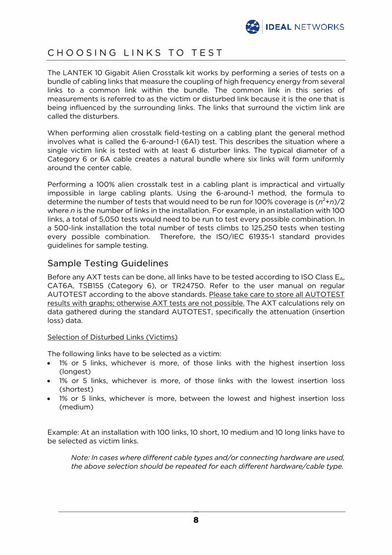
Sample Testing Guidelines Before any AXT tests can be done, all links have to be tested according to ISO Class EA, CAT6A, TSB155 (Category 6), or TR24750. Refer to the user manual on regular AUTOTEST according to the above standards. Please take care to store all AUTOTEST results with graphs; otherwise AXT tests are not possible. The AXT calculations rely on data gathered during the standard AUTOTEST, specifically the attenuation (insertion loss) data.
Selection of Disturbed Links (Victims)
The following links have to be selected as a victim: • 1% or 5 links, whichever is more, of those links with the highest insertion loss
(longest) • 1% or 5 links, whichever is more, of those links with the lowest insertion loss
(shortest) • 1% or 5 links, whichever is more, between the lowest and highest insertion loss
(medium)
Example: At an installation with 100 links, 10 short, 10 medium and 10 long links have to be selected as victim links.
Note: In cases where different cable types and/or connecting hardware are used, the above selection should be repeated for each different hardware/cable type.
9
Selection of Disturber Links
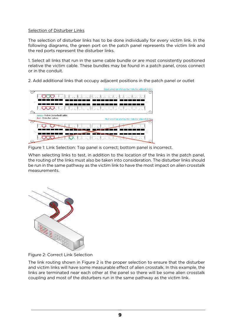
The selection of disturber links has to be done individually for every victim link. In the following diagrams, the green port on the patch panel represents the victim link and the red ports represent the disturber links.
1. Select all links that run in the same cable bundle or are most consistently positioned relative the victim cable. These bundles may be found in a patch panel, cross connect or in the conduit.
2. Add additional links that occupy adjacent positions in the patch panel or outlet
Figure 1: Link Selection: Top panel is correct; bottom panel is incorrect.
When selecting links to test, in addition to the location of the links in the patch panel, the routing of the links must also be taken into consideration. The disturber links should be run in the same pathway as the victim link to have the most impact on alien crosstalk measurements.
Figure 2: Correct Link Selection
The link routing shown in Figure 2 is the proper selection to ensure that the disturber and victim links will have some measurable effect of alien crosstalk. In this example, the links are terminated near each other at the panel so there will be some alien crosstalk coupling and most of the disturbers run in the same pathway as the victim link.
10
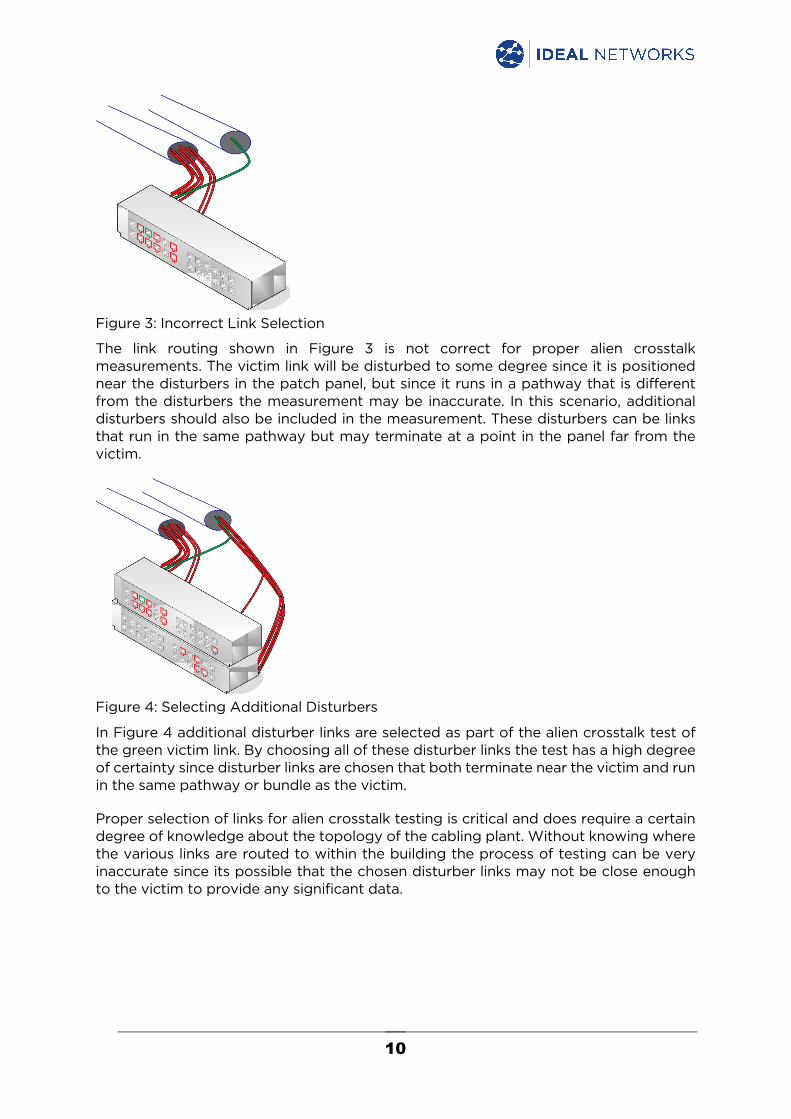
Figure 3: Incorrect Link Selection
The link routing shown in Figure 3 is not correct for proper alien crosstalk measurements. The victim link will be disturbed to some degree since it is positioned near the disturbers in the patch panel, but since it runs in a pathway that is different from the disturbers the measurement may be inaccurate. In this scenario, additional disturbers should also be included in the measurement. These disturbers can be links that run in the same pathway but may terminate at a point in the panel far from the victim.
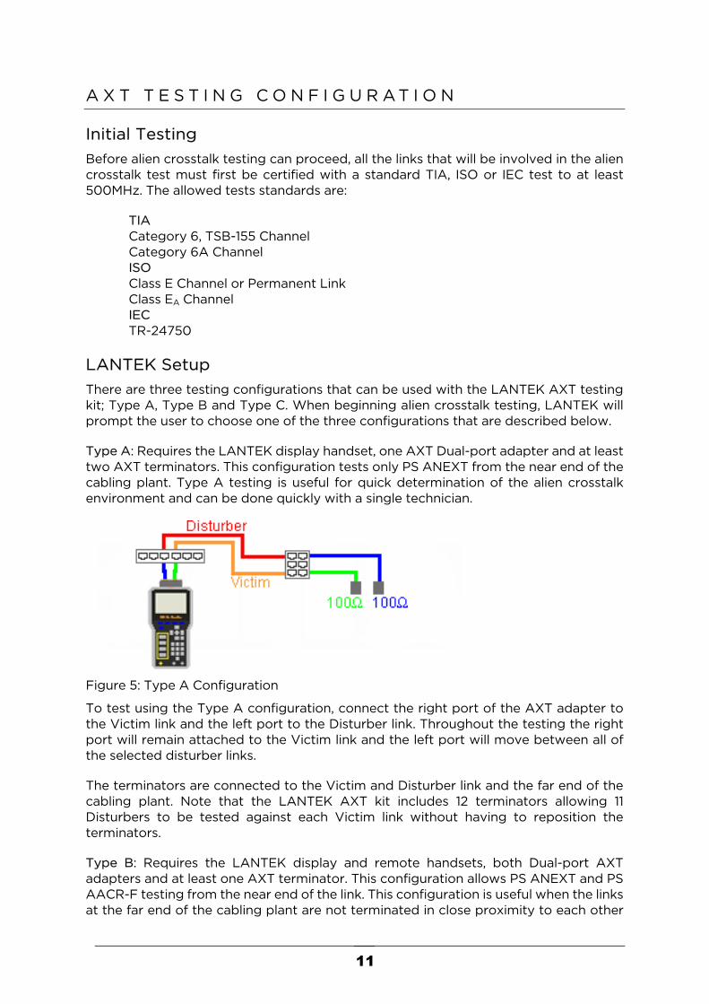
Figure 4: Selecting Additional Disturbers
In Figure 4 additional disturber links are selected as part of the alien crosstalk test of the green victim link. By choosing all of these disturber links the test has a high degree of certainty since disturber links are chosen that both terminate near the victim and run in the same pathway or bundle as the victim.
Proper selection of links for alien crosstalk testing is critical and does require a certain degree of knowledge about the topology of the cabling plant. Without knowing where the various links are routed to within the building the process of testing can be very inaccurate since its possible that the chosen disturber links may not be close enough to the victim to provide any significant data.
11
A X T T E S T I N G C O N F I G U R A T I O N
Initial Testing Before alien crosstalk testing can proceed, all the links that will be involved in the alien crosstalk test must first be certified with a standard TIA, ISO or IEC test to at least 500MHz. The allowed tests standards are:
TIA Category 6, TSB-155 Channel Category 6A Channel
ISO Class E Channel or Permanent Link Class EA Channel IEC TR-24750 LANTEK Setup There are three testing configurations that can be used with the LANTEK AXT testing kit; Type A, Type B and Type C. When beginning alien crosstalk testing, LANTEK will prompt the user to choose one of the three configurations that are described below.
Type A: Requires the LANTEK display handset, one AXT Dual-port adapter and at least two AXT terminators. This configuration tests only PS ANEXT from the near end of the cabling plant. Type A testing is useful for quick determination of the alien crosstalk environment and can be done quickly with a single technician.
Figure 5: Type A Configuration
To test using the Type A configuration, connect the right port of the AXT adapter to the Victim link and the left port to the Disturber link. Throughout the testing the right port will remain attached to the Victim link and the left port will move between all of the selected disturber links.
The terminators are connected to the Victim and Disturber link and the far end of the cabling plant. Note that the LANTEK AXT kit includes 12 terminators allowing 11 Disturbers to be tested against each Victim link without having to reposition the terminators.
Type B: Requires the LANTEK display and remote handsets, both Dual-port AXT adapters and at least one AXT terminator. This configuration allows PS ANEXT and PS AACR-F testing from the near end of the link. This configuration is useful when the links at the far end of the cabling plant are not terminated in close proximity to each other
12
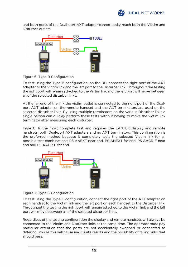
and both ports of the Dual-port AXT adapter cannot easily reach both the Victim and Disturber outlets.
Figure 6: Type B Configuration
To test using the Type B configuration, on the DH, connect the right port of the AXT adapter to the Victim link and the left port to the Disturber link. Throughout the testing the right port will remain attached to the Victim link and the left port will move between all of the selected disturber links.
At the far end of the link the victim outlet is connected to the right port of the Dual-port AXT adapter on the remote handset and the AXT terminators are used on the selected disturber links. By using multiple terminators on the various Disturber links a single person can quickly perform these tests without having to move the victim link terminator after measuring each disturber.
Type C: Is the most complete test and requires the LANTEK display and remote handsets, both Dual-port AXT adapters and no AXT terminators. This configuration is the preferred method because it completely tests the selected Victim link for all possible test combinations; PS ANEXT near end, PS ANEXT far end, PS AACR-F near end and PS AACR-F far end.
Figure 7: Type C Configuration
To test using the Type C configuration, connect the right port of the AXT adapter on each handset to the Victim link and the left port on each handset to the Disturber link. Throughout the testing the right port will remain attached to the Victim link and the left port will move between all of the selected disturber links.
Regardless of the testing configuration the display and remote handsets will always be connected to the Victim and Disturber links at the same time. The operator must pay particular attention that the ports are not accidentally swapped or connected to differing links as this will cause inaccurate results and the possibility of failing links that should pass.

13
Configuration PS
ANEXT NE PS
ANEXT FE PS
AACR-F NE PS
AACR-F FE
Type A ü
Type B ü ü Type C ü ü ü ü
Table 1: Test Configuration Capabilities
14
F I E L D C A L I B R A T I O N
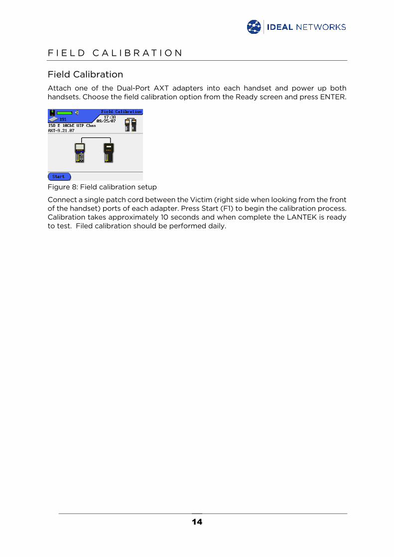
Field Calibration Attach one of the Dual-Port AXT adapters into each handset and power up both handsets. Choose the field calibration option from the Ready screen and press ENTER.
Figure 8: Field calibration setup
Connect a single patch cord between the Victim (right side when looking from the front of the handset) ports of each adapter. Press Start (F1) to begin the calibration process. Calibration takes approximately 10 seconds and when complete the LANTEK is ready to test. Filed calibration should be performed daily.
15
R U N N I N G A X T T E S T S
Select Victim Link
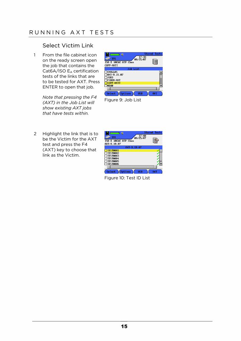
1 From the file cabinet icon on the ready screen open the job that contains the Cat6A/ISO EA certification tests of the links that are to be tested for AXT. Press ENTER to open that job.
Note that pressing the F4 (AXT) in the Job List will show existing AXT jobs that have tests within.
Figure 9: Job List
2 Highlight the link that is to be the Victim for the AXT test and press the F4 (AXT) key to choose that link as the Victim.
Figure 10: Test ID List
16
Select Test Configuration
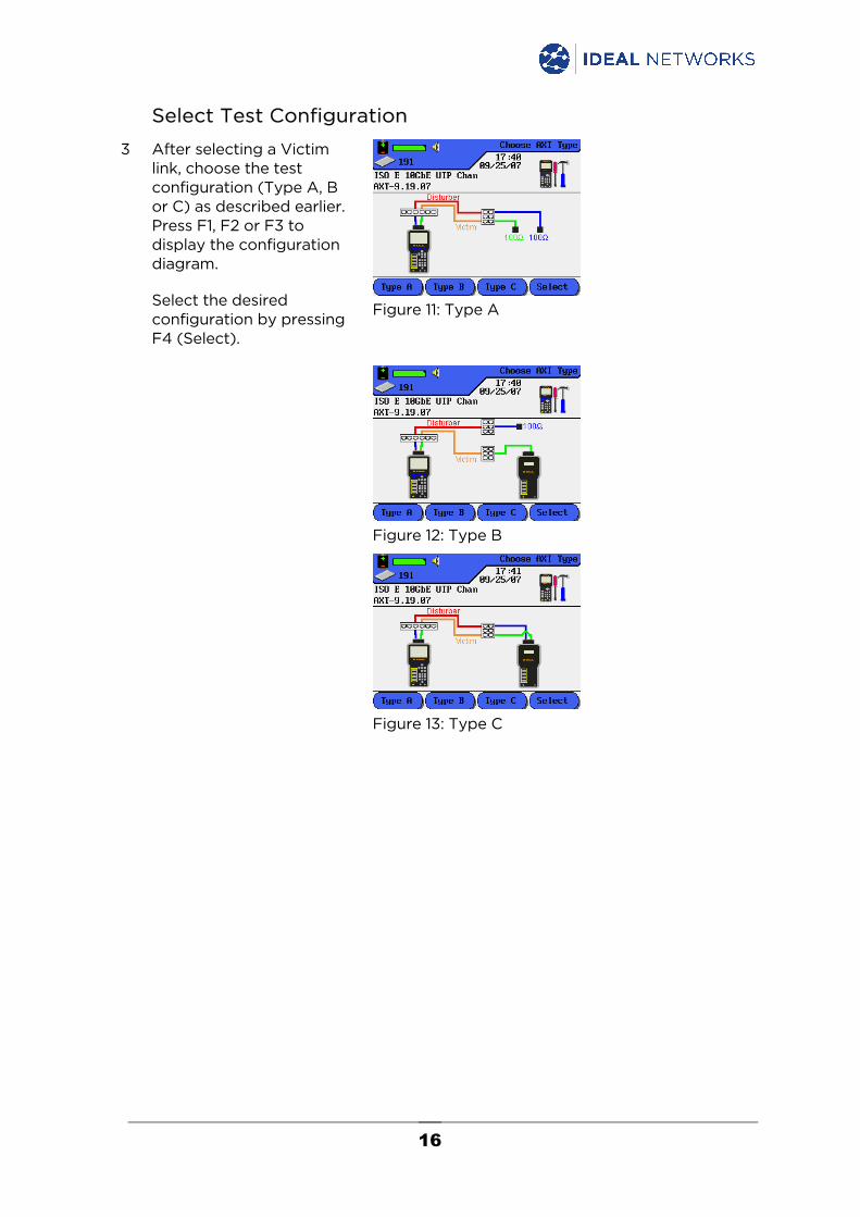
3 After selecting a Victim link, choose the test configuration (Type A, B or C) as described earlier. Press F1, F2 or F3 to display the configuration diagram.
Select the desired configuration by pressing F4 (Select).
Figure 11: Type A
Figure 12: Type B
Figure 13: Type C
17
Select Disturber Links
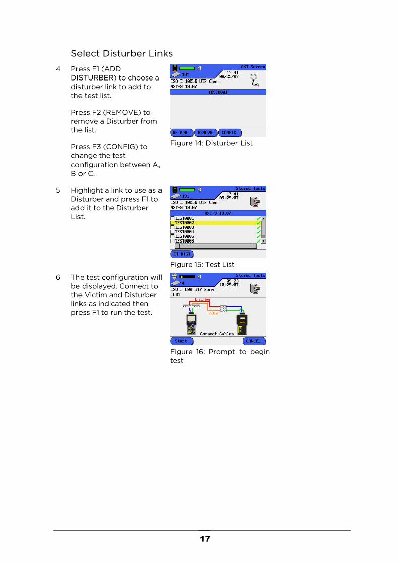
4 Press F1 (ADD DISTURBER) to choose a disturber link to add to the test list.
Press F2 (REMOVE) to remove a Disturber from the list.
Press F3 (CONFIG) to change the test configuration between A, B or C.
Figure 14: Disturber List
5 Highlight a link to use as a Disturber and press F1 to add it to the Disturber List.
Figure 15: Test List
6 The test configuration will be displayed. Connect to the Victim and Disturber links as indicated then press F1 to run the test.
Figure 16: Prompt to begin test
18
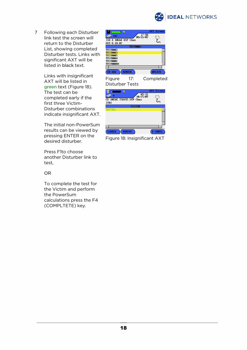
7 Following each Disturber link test the screen will return to the Disturber List, showing completed Disturber tests. Links with significant AXT will be listed in black text.
Links with insignificant AXT will be listed in green text (Figure 18). The test can be completed early if the first three Victim-Disturber combinations indicate insignificant AXT.
The initial non-PowerSum results can be viewed by pressing ENTER on the desired disturber.
Press F1to choose another Disturber link to test,
OR
To complete the test for the Victim and perform the PowerSum calculations press the F4 (COMPLTETE) key.
Figure 17: Completed Disturber Tests
Figure 18: Insignificant AXT
19
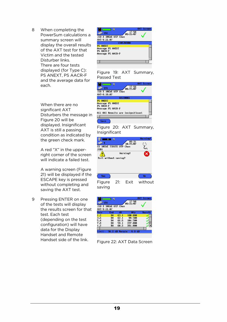
8 When completing the PowerSum calculations a summary screen will display the overall results of the AXT test for that Victim and the tested Disturber links. There are four tests displayed (for Type C): PS ANEXT, PS AACR-F and the average data for each.
When there are no significant AXT Disturbers the message in Figure 20 will be displayed. Insignificant AXT is still a passing condition as indicated by the green check mark.
A red “X” in the upper-right corner of the screen will indicate a failed test.
A warning screen (Figure 21) will be displayed if the ESCAPE key is pressed without completing and saving the AXT test.
Figure 19: AXT Summary, Passed Test
Figure 20: AXT Summary, Insignificant
Figure 21: Exit without saving
9 Pressing ENTER on one of the tests will display the results screen for that test. Each test (depending on the test configuration) will have data for the Display Handset and Remote Handset side of the link.
Figure 22: AXT Data Screen

20
Pressing ENTER on one of the pairs will display the plot data for the pair.
Figure 23: AXT Plot Data
10 Return to step 2 to select another Victim link to test.
21
V I E W I N G T E S T R E S U L T S
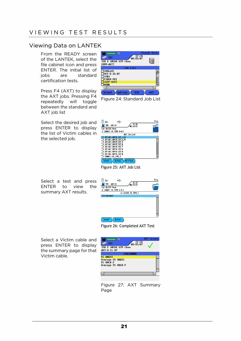
Viewing Data on LANTEK From the READY screen
of the LANTEK, select the file cabinet icon and press ENTER. The initial list of jobs are standard certification tests.
Press F4 (AXT) to display the AXT jobs. Pressing F4 repeatedly will toggle between the standard and AXT job list
Figure 24: Standard Job List
Select the desired job and press ENTER to display the list of Victim cables in the selected job.
Figure 25: AXT Job List
Select a test and press
ENTER to view the summary AXT results.
Figure 26: Completed AXT Test
Select a Victim cable and
press ENTER to display the summary page for that Victim cable.
Figure 27: AXT Summary Page
22
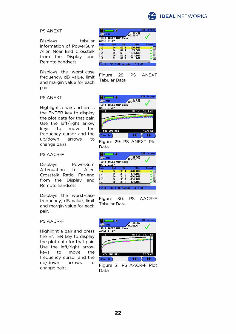
PS ANEXT
Displays tabular information of PowerSum Alien Near End Crosstalk from the Display and Remote handsets
Displays the worst-case frequency, dB value, limit and margin value for each pair.
Figure 28: PS ANEXT Tabular Data
PS ANEXT
Highlight a pair and press the ENTER key to display the plot data for that pair. Use the left/right arrow keys to move the frequency cursor and the up/down arrows to change pairs.
Figure 29: PS ANEXT Plot Data
PS AACR-F
Displays PowerSum Attenuation to Alien Crosstalk Ratio, Far-end from the Display and Remote handsets.
Displays the worst-case frequency, dB value, limit and margin value for each pair.
Figure 30: PS AACR-F Tabular Data
PS AACR-F
Highlight a pair and press the ENTER key to display the plot data for that pair. Use the left/right arrow keys to move the frequency cursor and the up/down arrows to change pairs.
Figure 31: PS AACR-F Plot Data
23
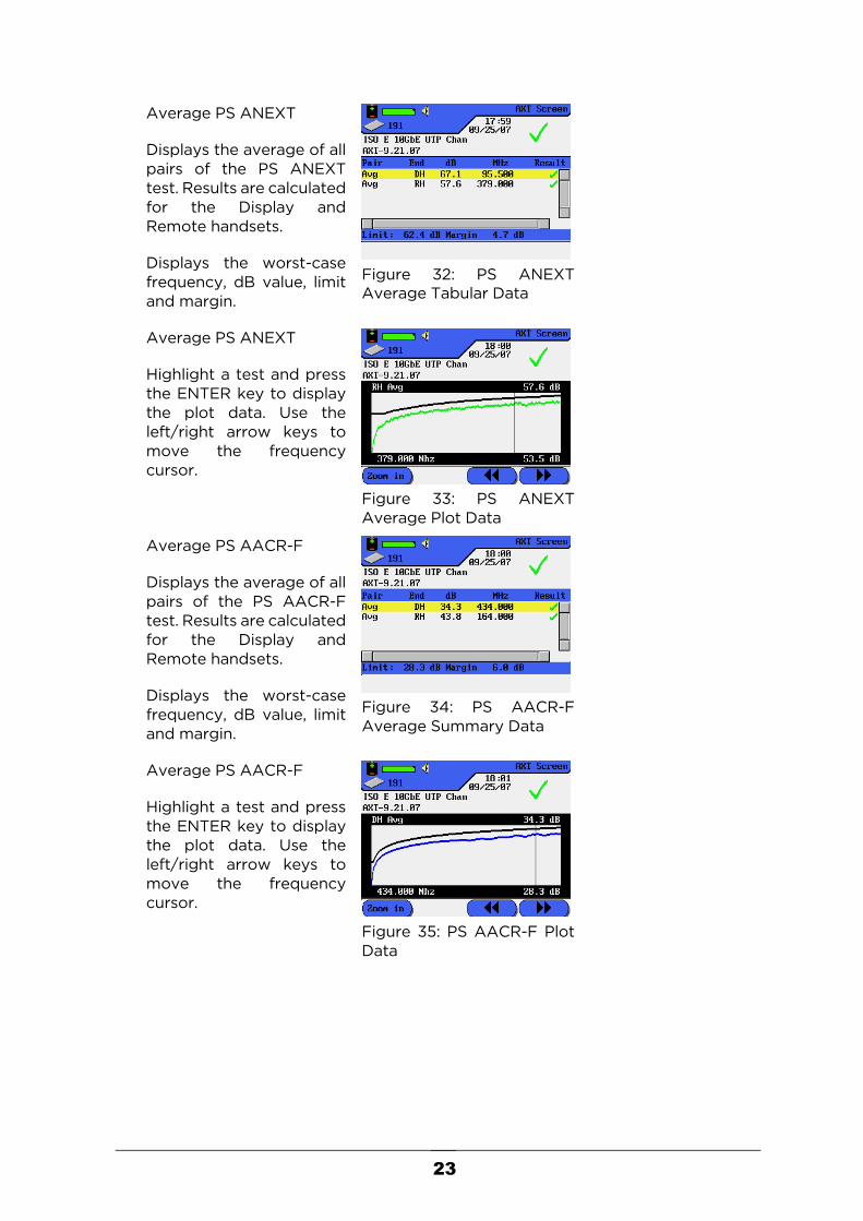
Average PS ANEXT
Displays the average of all pairs of the PS ANEXT test. Results are calculated for the Display and Remote handsets.
Displays the worst-case frequency, dB value, limit and margin.
Figure 32: PS ANEXT Average Tabular Data
Average PS ANEXT
Highlight a test and press the ENTER key to display the plot data. Use the left/right arrow keys to move the frequency cursor.
Figure 33: PS ANEXT Average Plot Data
Average PS AACR-F
Displays the average of all pairs of the PS AACR-F test. Results are calculated for the Display and Remote handsets.
Displays the worst-case frequency, dB value, limit and margin.
Figure 34: PS AACR-F Average Summary Data
Average PS AACR-F
Highlight a test and press the ENTER key to display the plot data. Use the left/right arrow keys to move the frequency cursor.
Figure 35: PS AACR-F Plot Data
24
P R I N T I N G A X T R E P O R T S
To prepare printed AXT reports the data must be imported from the LANTEK to the PC using the LANTEK AXT Viewer. This software is available for download from the IDEAL Networks website.
The software is used to view and print reports only and cannot be used to modify the test data.
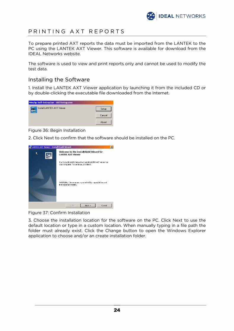
Installing the Software 1. Install the LANTEK AXT Viewer application by launching it from the included CD or by double-clicking the executable file downloaded from the Internet.
Figure 36: Begin Installation
2. Click Next to confirm that the software should be installed on the PC.
Figure 37: Confirm Installation
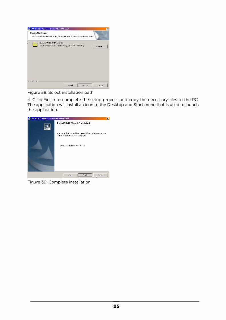
3. Choose the installation location for the software on the PC. Click Next to use the default location or type in a custom location. When manually typing in a file path the folder must already exist. Click the Change button to open the Windows Explorer application to choose and/or an create installation folder.
25
Figure 38: Select installation path
4. Click Finish to complete the setup process and copy the necessary files to the PC. The application will install an icon to the Desktop and Start menu that is used to launch the application.
Figure 39: Complete installation
26
Creating Projects 1. A project is a folder on the computer’s hard drive where files are copied from the
LANTEK and certain information about the job can be saved. To better organize data, each job tested in the field should be saved in a new project.
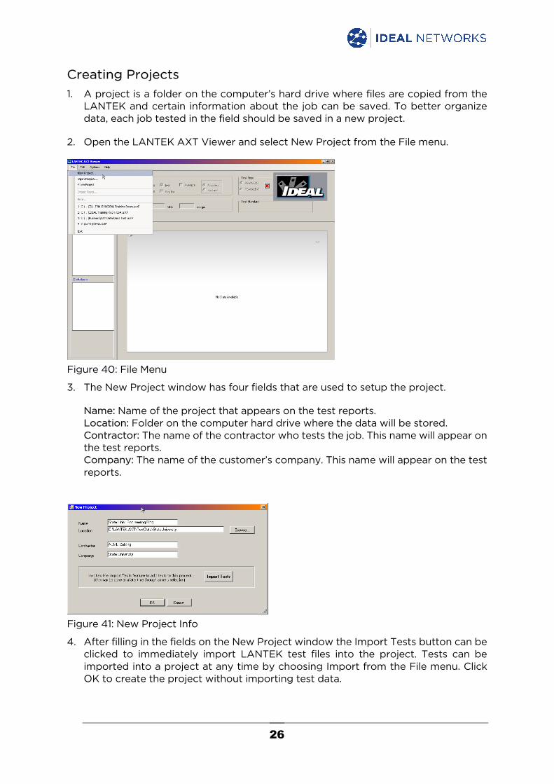
2. Open the LANTEK AXT Viewer and select New Project from the File menu.
Figure 40: File Menu
3. The New Project window has four fields that are used to setup the project.
Name: Name of the project that appears on the test reports. Location: Folder on the computer hard drive where the data will be stored. Contractor: The name of the contractor who tests the job. This name will appear on the test reports. Company: The name of the customer’s company. This name will appear on the test reports.
Figure 41: New Project Info
4. After filling in the fields on the New Project window the Import Tests button can be clicked to immediately import LANTEK test files into the project. Tests can be imported into a project at any time by choosing Import from the File menu. Click OK to create the project without importing test data.

27
Importing Test Data The data import process depends on the model of LanTEK from which the data is being imported.
LanTEK I
When importing tests, click the Browse button to select the source of the data. Since all data is stored on the LANTEK Compact Flash card the data can be uploaded in one of two ways:
A. Place the Compact Flash card into the PC or use a USB card reader to access the Compact Flash card. Or;
B. Connect to the LANTEK with a USB cable, boot the LANTEK, press the F2, then F3 keys to allow Windows to recognize the drive. Make sure the Compact Flash card is selected as the current Save Media in the LANTEK Preferences menu.
In the AXT PC software, click the Browse button and navigate to the AXT test folder on the Compact Flash card and select the job that contains the desired tests.
When Browse is clicked the Windows Explorer tree will be displayed.
A. Locate the CF card in the directory tree. In this example below, the drive named LANTEK_CF is located under My Computer.
B. Under the “stored_tests” folder there will be a folder for each certification job
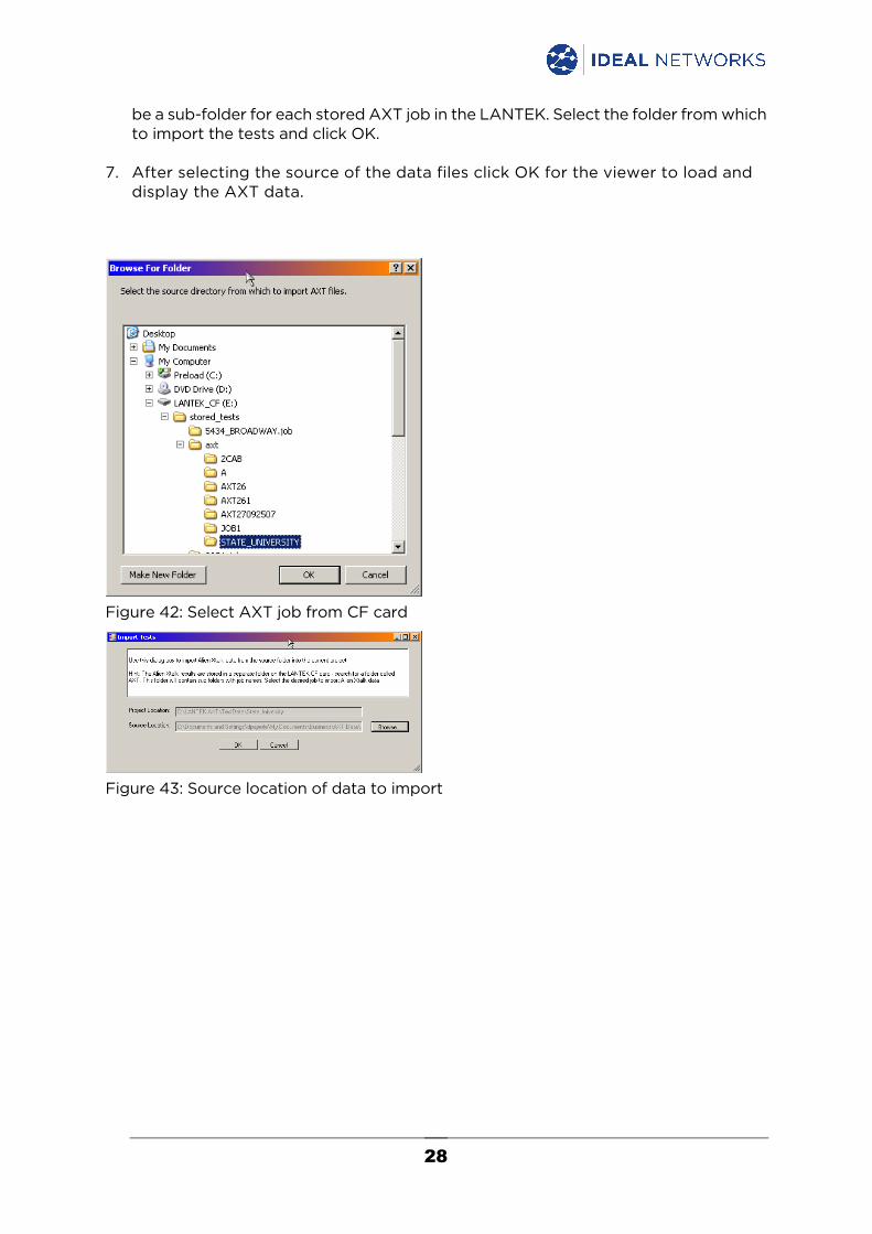
and a single folder that contains all of the AXT jobs. The standard certification job folders have the file extension “.job”. Open the folder named “axt”. In the “axt” folder will be a sub-folder for each stored AXT job in the LANTEK. Select the folder from which to import the tests and click OK.
Click OK to confirm the project and source data locations and import the data files into the project.
LanTEK II/III
Test results for LanTEK II and LanTEK III are copied to a USB flash drive then imported into the AXT reporter software.
1. Connect a USB flash drive into the LanTEK.
2. Open the JOBS screen in the LanTEK and highlight the AXT job to be copied.
3. Press F1, highlight Copy Selected Jobs to USB and press ENTER.
4. Remove the USB flash drive from the LanTEK and connect it to the computer.
5. Click the Browse button and navigate to the AXT test folder on the USB flash drive and select the job that contains the desired tests.
When Browse is clicked the Windows Explorer tree will be displayed.
6. Under the “stored_tests” folder there will be a folder for each certification job and a single folder that contains all of the AXT jobs. The standard certification job folders have the file extension “.job”. Open the folder named “axt”. In the “axt” folder will
28
be a sub-folder for each stored AXT job in the LANTEK. Select the folder from which to import the tests and click OK.
7. After selecting the source of the data files click OK for the viewer to load and display the AXT data.
Figure 42: Select AXT job from CF card
Figure 43: Source location of data to import
29
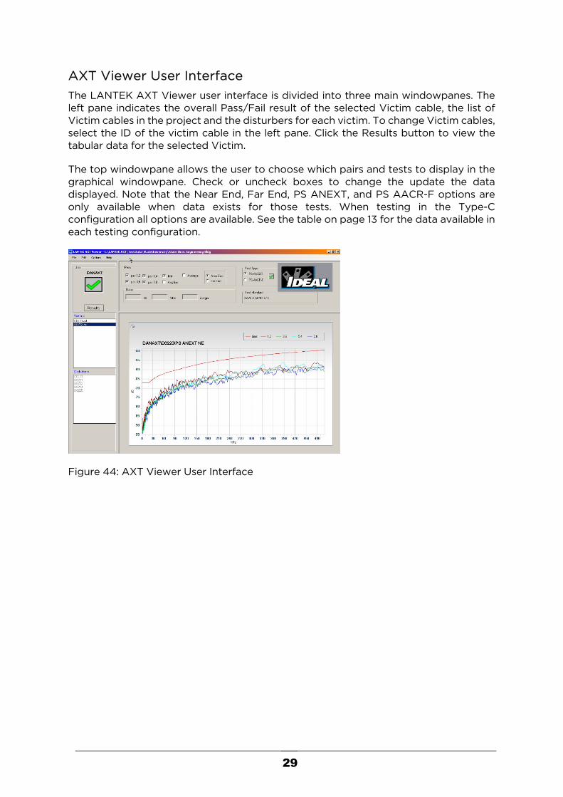
AXT Viewer User Interface The LANTEK AXT Viewer user interface is divided into three main windowpanes. The left pane indicates the overall Pass/Fail result of the selected Victim cable, the list of Victim cables in the project and the disturbers for each victim. To change Victim cables, select the ID of the victim cable in the left pane. Click the Results button to view the tabular data for the selected Victim.
The top windowpane allows the user to choose which pairs and tests to display in the graphical windowpane. Check or uncheck boxes to change the update the data displayed. Note that the Near End, Far End, PS ANEXT, and PS AACR-F options are only available when data exists for those tests. When testing in the Type-C configuration all options are available. See the table on page 13 for the data available in each testing configuration.
Figure 44: AXT Viewer User Interface

30
Position the mouse cursor over the plot and hold down the left button to place a crosshair over the plot and reveal the dB, frequency, and margin at the cursor position.
Figure 45: Cursor Details – Left click over the chart
The bottom windowpane displays the graphical data for the AXT test. The user has the option of customizing the graphical display by right clicking on the X or Y-axis and selecting Properties. Settings for colors, scale, labeling, tick marks and many other options can be changed.
Figure 46: Chart Options

31
Printing Reports To print a standard report click Print from the File menu. There are options to print reports for all the victims or just the selected Victims. One or multiple victims can be selected in the left windowpane by holding down the “Ctrl” key while clicking each Victim.
Figure 47: Print menu – print all tests or only selected tests
Figure 48: Standard printed report
In addition to printing a complete report, a full-page printout of the current graphical display can be generated by clicking the small printer icon above and to the left of the graphic display in the user interface.
Figure 49: Printing full-page graph

32
Clicking the graph button will open the print window. The page printed will contain just the graph and victim ID.
Figure 50: Print window
Figure 51: Full-page graphical printout
Closing Projects The project is automatically saved every time new files are imported into the project so there is no need to save the project before closing. To close a Project, click File, then Close.
Copying Projects A project can be easily copied to another PC by copying all of the files from the desired project to a CD or other movable media.
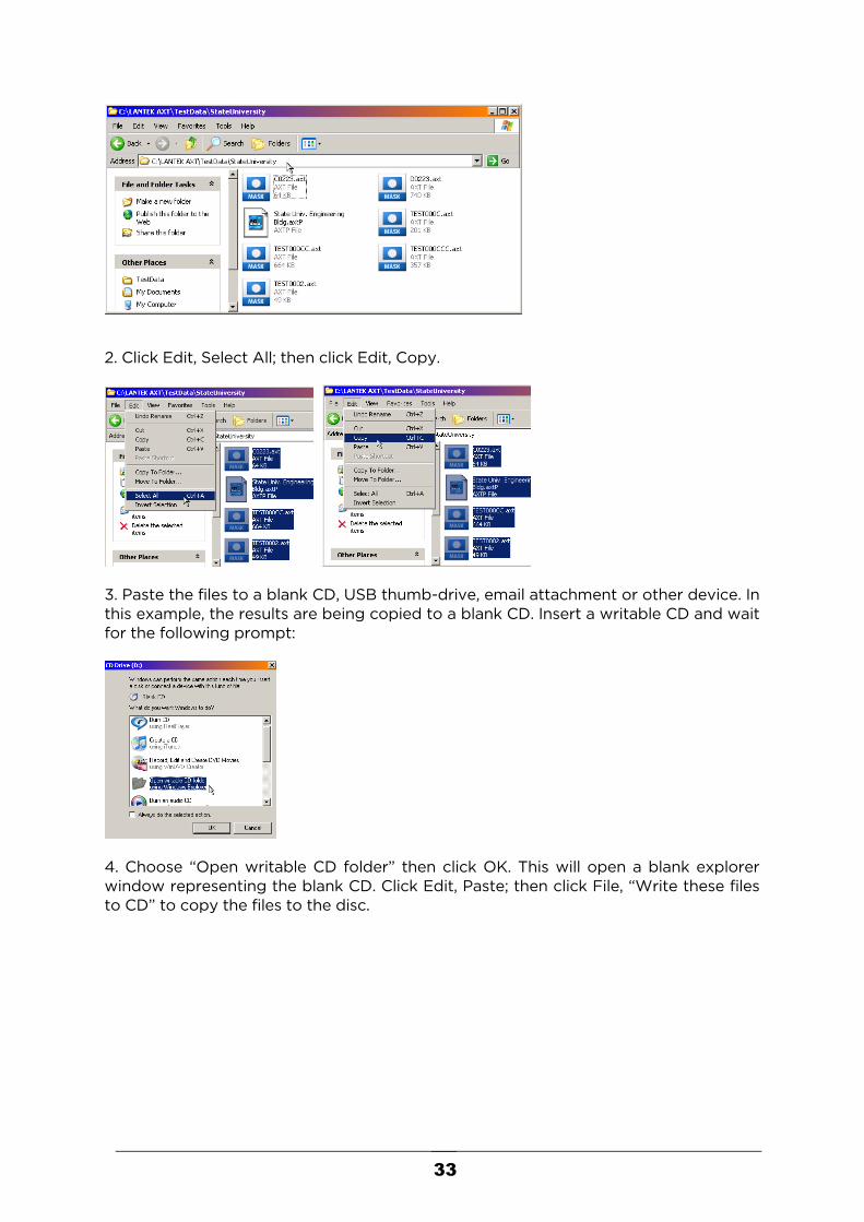
1. Open the folder of the project to be copied. In this example, the files are located in “C:\LANTEK AXT\TestData\StateUniversity”
33
2. Click Edit, Select All; then click Edit, Copy.
3. Paste the files to a blank CD, USB thumb-drive, email attachment or other device. In this example, the results are being copied to a blank CD. Insert a writable CD and wait for the following prompt:
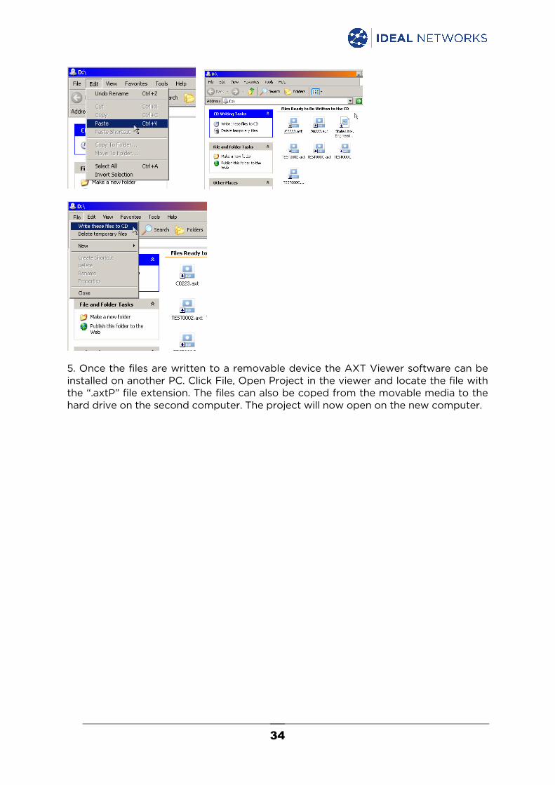
4. Choose “Open writable CD folder” then click OK. This will open a blank explorer window representing the blank CD. Click Edit, Paste; then click File, “Write these files to CD” to copy the files to the disc.
34
5. Once the files are written to a removable device the AXT Viewer software can be installed on another PC. Click File, Open Project in the viewer and locate the file with the “.axtP” file extension. The files can also be coped from the movable media to the hard drive on the second computer. The project will now open on the new computer.

35
C U S T O M E R S E R V I C E
Technical Assistance For technical assistance or service questions locate your local service center at www.idealnetworks.net.
IDEAL INDUSTRIES, INC. 1122 Park Avenue, Sycamore IL 60178 USA Tel: 800-947-3612 Tel: 815-895-5181 E-Mail: [email protected] IDEAL INDUSTRIES (CANADA), INC. 33 Fuller Road, Ajax, Ontario, L1S 2E1 Canada Tel: 800 8243325 Fax: 800 2633115 E-Mail: [email protected] IDEAL NETWORKS Unit 3, Europa Court, Europa Boulevard, Westbrook, Warrington, Cheshire, WA5 7TN, United Kingdom Tel: +44 (0)1925 444 446 Fax: +44 (0)1925 44 55 01 E-Mail: [email protected] IDEAL INDUSTRIES GmbH Gutenbergstr. 10, 85737 Ismaning, Germany Tel: +49 (0)89 99 686-0 Fax: +49 (0)89 99 686-111 Tech. Hotline: +49 (0)89 99 686-200 E-Mail: [email protected] IDEAL NETWORKS (FRANCE) Route de Gisy - ZA Burospace - Bâtiment 23 - 91570 Bièvres - France Tel: +33 (0)1 69 35 54 70 Tech. Hotline: +33(0)1 69 35 54 75 Fax: +33(0)1 60 19 00 48 E-Mail: [email protected] IDEAL INDUSTRIES ASIA LIMITED 上海市浦东新区川桥路1295号金桥数研基地1栋305室 Room 305, Building 1, No.1295, Chuanqiao Road, Pudong New District Shanghai, China Tel: +86 (0)21-31263188 E-Mail: [email protected]

36
IDEAL INDUSTRIES BRAZIL Domo Business, Rua José Versolato, 111 - Bloco B - Sala 826, São Bernardo do Campo - SP - 09750-730, Brasil Tel: +55 (0)1143149930 E-Mail: [email protected] IDEAL INDUSTRIES MEXICO Paseo de los Adobes 1079-10, Ferran 3, Guadalajara Technology Park, Zapopan Jalisco, MEXICO C.P. 45010 Tel: +52 (0)5524888129 E-Mail: [email protected] IDEAL INDUSTRIES India Pvt Ltd 229 - 230, Spazedge, Tower B, Sector 47, Sohna Road, Gurgaon, 122001 Haryana, India Tel: +91 956 0075 905 E-Mail: [email protected] IDEAL INDUSTRIES AUSTRALIA 17/35 Dunlop Road, Mulgrave VIC 3170, Australia Tel: +61 3 9562 0175 Mobile: +61 455 843 325 Email: [email protected]
Part Number 1618332 Rev 1.