16102 Revision: Effective Date: By: Coyote Power Steering kit · Attach the remaining line to the...
13
Controlled Documentation DO NOT DUPLICATE. CONFIDENTIAL INFORMATION AND PROTECTED UNDER U.S. COPYRIGHT LAWS 2015 FACTORY FIVE RACING, INC. company\instructions\Power steering Coyote ROADSTER-COUPE 1 Part Number:16102 Revision: A Effective Date: 8/19/15 By: J. INGERSLEV Coyote Power Steering kit ROADSTER AND COUPE INSTALLATION INSTRUCTIONS Table of Contents Tools required ................................................................................. 2 Supplies needed ............................................................................. 2 Parts preparation ............................................................................ 2 Power steering pump bracket ................................................................... 2 Idler pulley mount ..................................................................................... 4 Installation ....................................................................................... 4 Idler Pulley mount ..................................................................................... 4 Power steering pump ................................................................................ 6
Transcript of 16102 Revision: Effective Date: By: Coyote Power Steering kit · Attach the remaining line to the...
Controlled Documentation
DO NOT DUPLICATE. CONFIDENTIAL INFORMATION AND PROTECTED UNDER U.S. COPYRIGHT LAWS 2015 FACTORY FIVE RACING, INC.
company\instructions\Power steering Coyote ROADSTER-COUPE
1
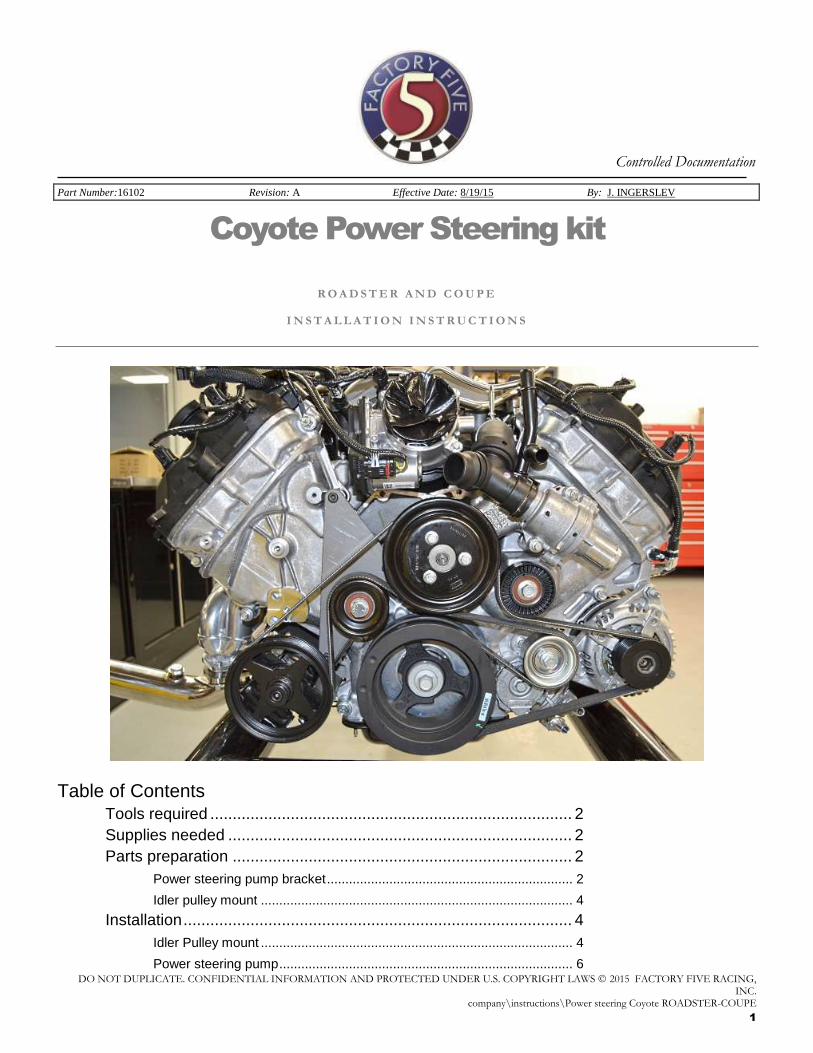
Part Number:16102 Revision: A Effective Date: 8/19/15 By: J. INGERSLEV
Coyote Power Steering kit
R O A D S T E R A N D C O U P E
I N S T A L L A T I O N I N S T R U C T I O N S
Table of Contents
Tools required ................................................................................. 2
Supplies needed ............................................................................. 2
Parts preparation ............................................................................ 2
Power steering pump bracket ................................................................... 2
Idler pulley mount ..................................................................................... 4
Installation ....................................................................................... 4
Idler Pulley mount ..................................................................................... 4
Power steering pump ................................................................................ 6
2
Power steering rack .................................................................................. 7
Power steering lines ............................................................................... 10
Bleeding the system ...................................................................... 12
Power steering alignment specifications ....................................... 13
Adjusting the upper control Arm ............................................................. 13
Tools required
¾” wrench
¾” Socket
Ratchet 5/32”, ¼”, 6mm Hex Keys
Jack stands
Floor jack
Needle Nose Pliers
Torque wrench
Supplies needed
Power steering fluid
Parts preparation
Power steering pump bracket
Power steering pump mount assembly
½” wrench, ¼” hex key
3
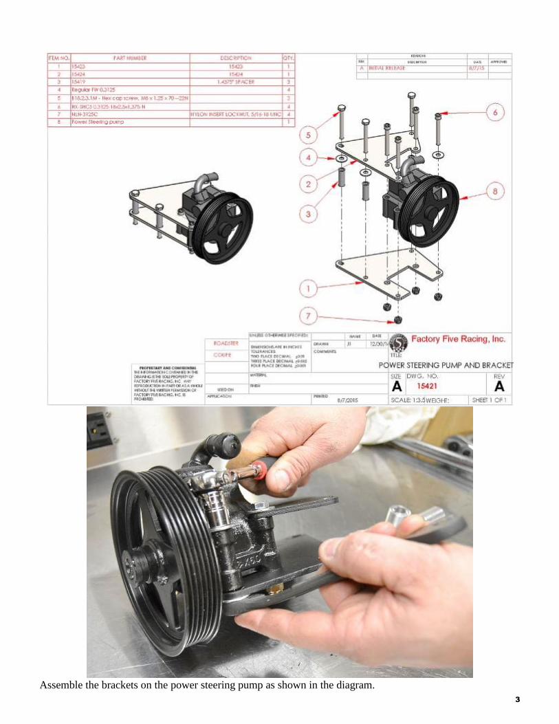
Assemble the brackets on the power steering pump as shown in the diagram.
4
Idler pulley mount
Idler pulley mount assembly
¾” wrench, ¾” socket, ratchet.
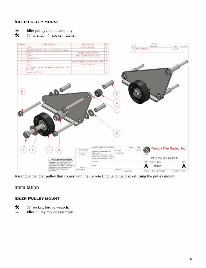
Assemble the idler pulley that comes with the Coyote Engine to the bracket using the pulley mount.
Installation
Idler Pulley mount
½” socket, torque wrench.
Idler Pulley mount assembly.
5
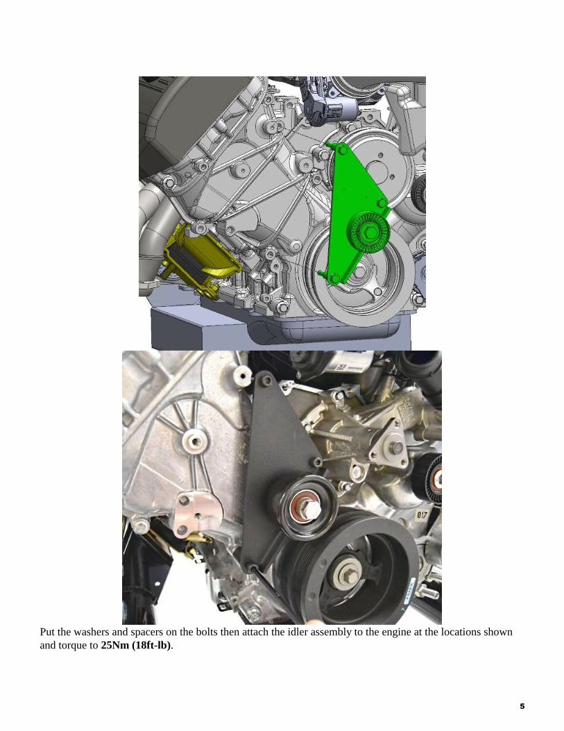
Put the washers and spacers on the bolts then attach the idler assembly to the engine at the locations shown
and torque to 25Nm (18ft-lb).
6
Power steering pump
Power steering pump assembly
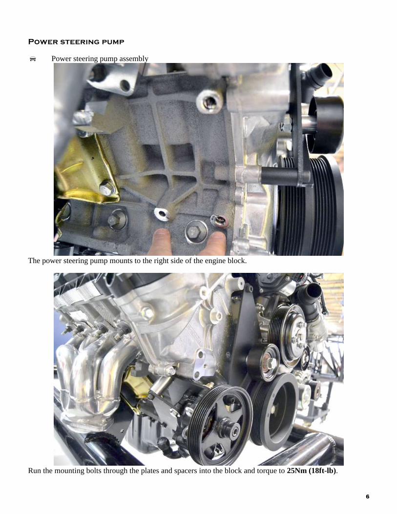
The power steering pump mounts to the right side of the engine block.
Run the mounting bolts through the plates and spacers into the block and torque to 25Nm (18ft-lb).
7
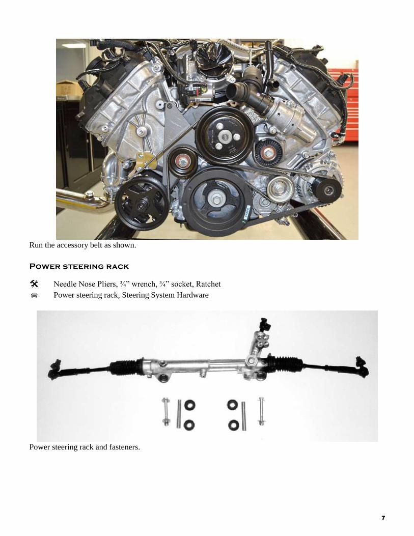
Run the accessory belt as shown.
Power steering rack
Needle Nose Pliers, ¾” wrench, ¾” socket, Ratchet
Power steering rack, Steering System Hardware
Power steering rack and fasteners.
8
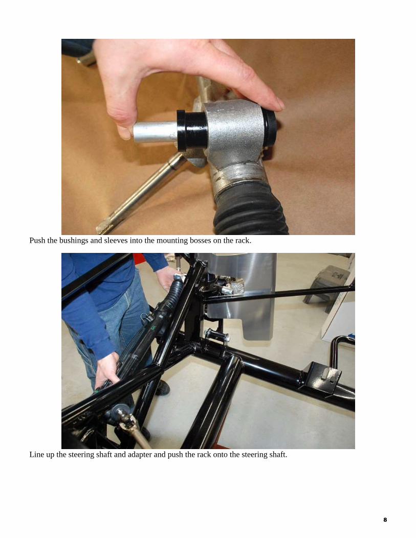
Push the bushings and sleeves into the mounting bosses on the rack.
Line up the steering shaft and adapter and push the rack onto the steering shaft.
9
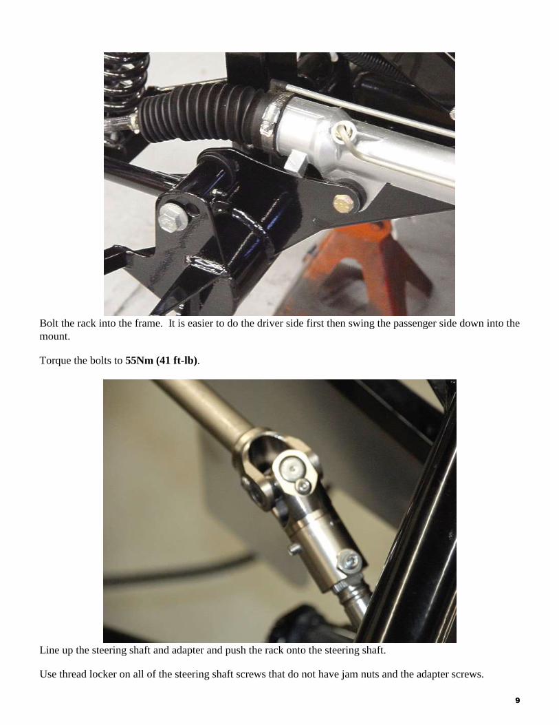
Bolt the rack into the frame. It is easier to do the driver side first then swing the passenger side down into the
mount.
Torque the bolts to 55Nm (41 ft-lb).
Line up the steering shaft and adapter and push the rack onto the steering shaft.
Use thread locker on all of the steering shaft screws that do not have jam nuts and the adapter screws.
10
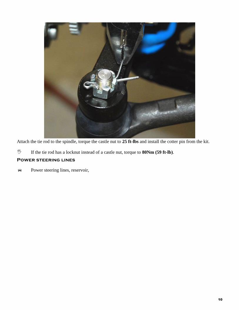
Attach the tie rod to the spindle, torque the castle nut to 25 ft-lbs and install the cotter pin from the kit.
If the tie rod has a locknut instead of a castle nut, torque to 80Nm (59 ft-lb).
Power steering lines
Power steering lines, reservoir,
11
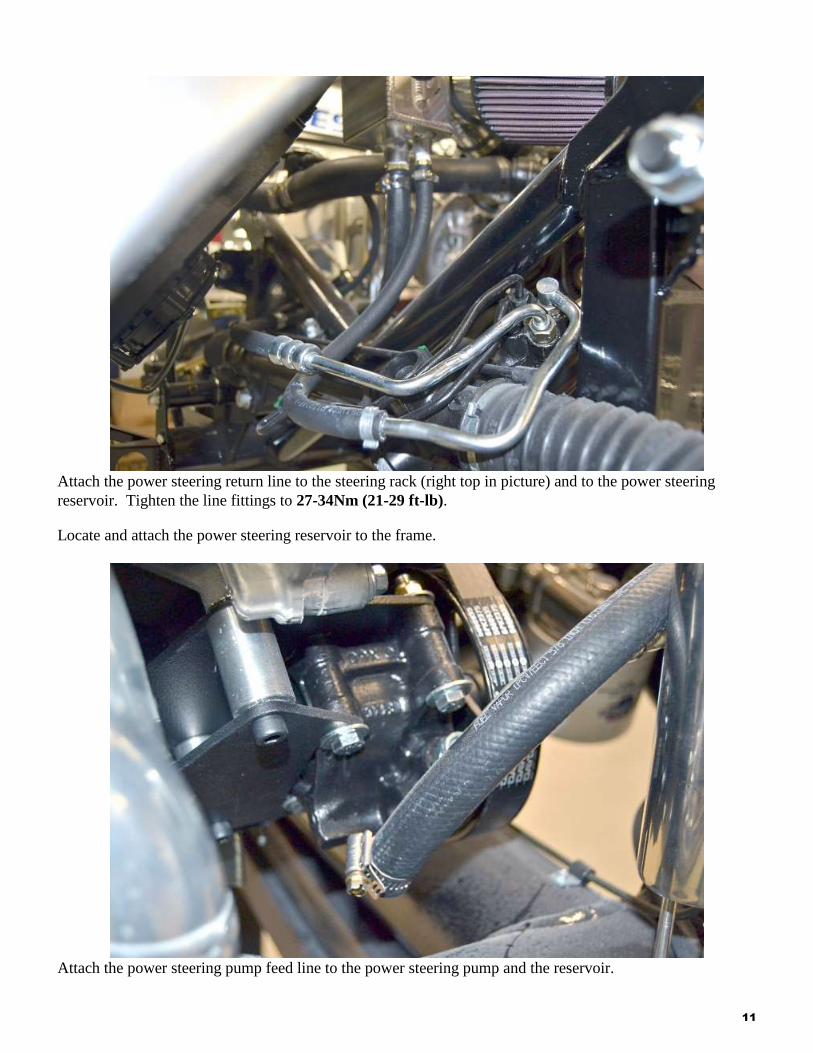
Attach the power steering return line to the steering rack (right top in picture) and to the power steering
reservoir. Tighten the line fittings to 27-34Nm (21-29 ft-lb).
Locate and attach the power steering reservoir to the frame.
Attach the power steering pump feed line to the power steering pump and the reservoir.
12
Attach the remaining line to the power steering pump and the steering rack.
Bleeding the system
Power steering fluid.
Jack, jack stands.
Jack the front of the car up so the front wheels are off the ground and place on jack stands.
Fill the power steering fluid reservoir with fluid.
Turn the steering wheel slowly lock to lock.
Check the steering fluid level.
Do not hold the steering wheel at full lock while bleading the system.
Start the engine and turn the steering wheel lock-to-lock.
Lower the car off the jack stands.
13
Power steering alignment specifications
Caster: 7
Camber: -0.5
Total Toe: 1/16”
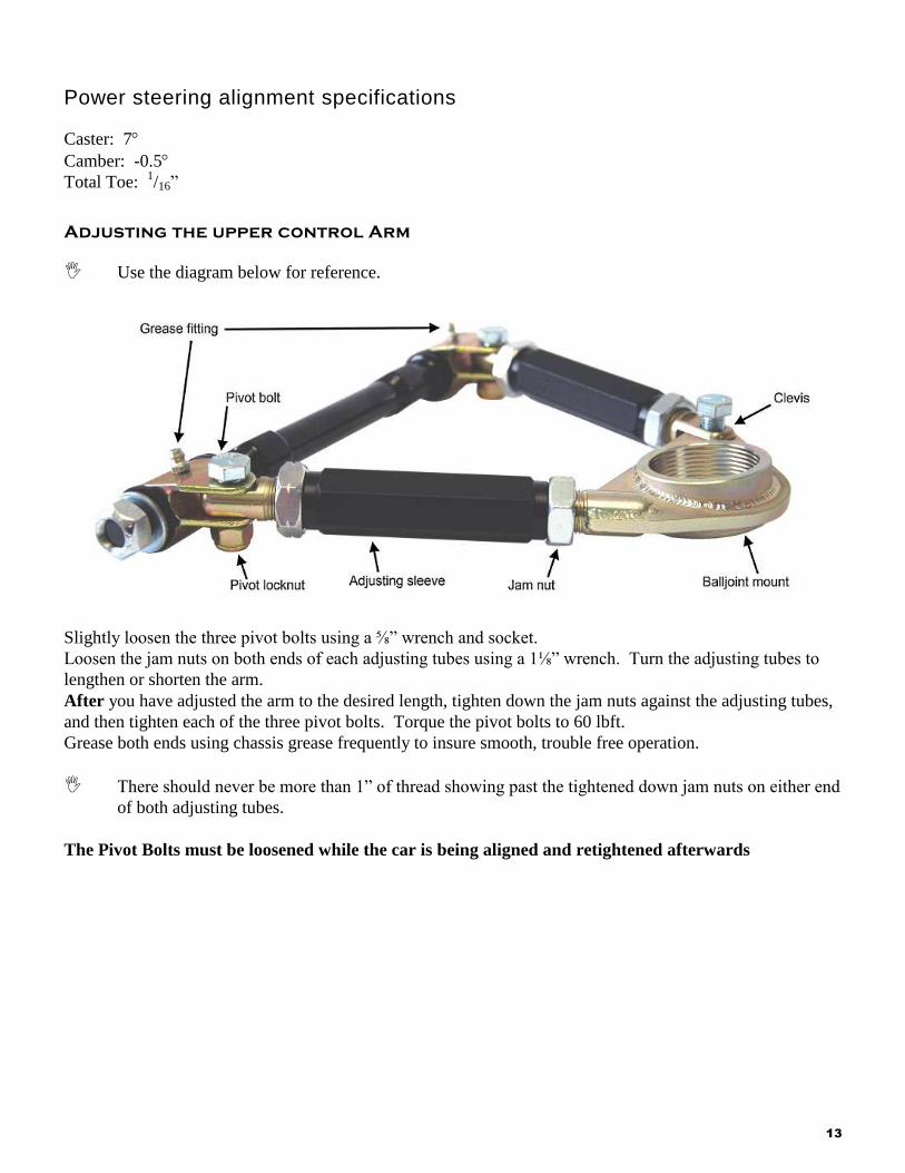
Adjusting the upper control Arm
Use the diagram below for reference.
Slightly loosen the three pivot bolts using a ⅝” wrench and socket.
Loosen the jam nuts on both ends of each adjusting tubes using a 1⅛” wrench. Turn the adjusting tubes to
lengthen or shorten the arm.
After you have adjusted the arm to the desired length, tighten down the jam nuts against the adjusting tubes,
and then tighten each of the three pivot bolts. Torque the pivot bolts to 60 lbft.
Grease both ends using chassis grease frequently to insure smooth, trouble free operation.
There should never be more than 1” of thread showing past the tightened down jam nuts on either end
of both adjusting tubes.
The Pivot Bolts must be loosened while the car is being aligned and retightened afterwards