161-kV OPTION E EVALUATION - WordPress.com
35
161-kV OPTION E EVALUATION Columbia Water & Light Option E Evaluation BMcD Project No. 104146 Revision 1 7/6/2018
Transcript of 161-kV OPTION E EVALUATION - WordPress.com

161-kV OPTION E EVALUATION
Columbia Water & Light
Option E Evaluation BMcD Project No. 104146
Revision 1 7/6/2018

161-kV OPTION E EVALUATION
prepared for
Columbia Water & Light Option E Evaluation
Columbia, MO
Project No. 104146
Revision 1 7/6/2018
prepared by
Burns & McDonnell Engineering Company, Inc. Kansas City, MO
COPYRIGHT © 2018 BURNS & McDONNELL ENGINEERING COMPANY, INC.
INDEX AND CERTIFICATION
Columbia Water & Light 161-kV OPTION E EVALUATION
Project No. 104146
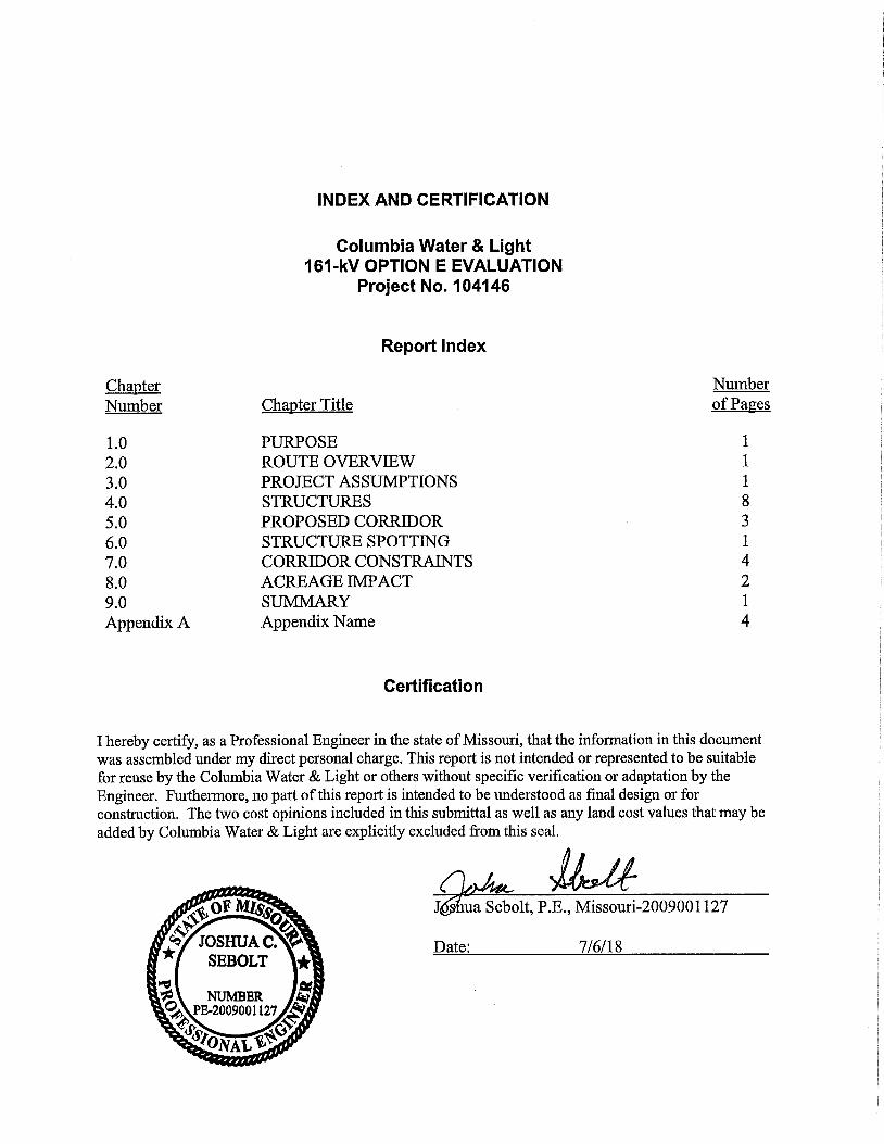
Report Index
ChanterNumber Chanter Title
Numberof Pages
1.0 PURPOSE 12.0 ROUTE OVERVIEW 13.0 PROJECT ASSUMPTIONS 14.0 STRUCTURES 85.0 PROPOSED CORRIDOR 36.0 STRUCTURE SPOTTING 17.0 CORRIDOR CONSTRAINTS 48.0 ACREAGE IMPACT 29.0 SUMMARY 1Appendix A Appendix Name 4
Certification
I hereby certify, as a Professional Engineer in the state of Missouri, that the information in this document was assembled under my direct personal charge. This report is not intended or represented to be suitable for reuse by the Columbia Water & Light or others without specific verification or adaptation by the Engineer. Furthermore, no part of this report is intended to be understood as final design or for construction. The two cost opinions included in this submittal as well as any land cost values that may be added by Columbia Water & Light are explicitly excluded from this seal.

Option E Evaluation Revision 1 Table of Contents
Columbia Water & Light TOC-1 Burns & McDonnell
TABLE OF CONTENTS
Page No.
1.0 PURPOSE ......................................................................................................... 1-1
2.0 ROUTE OVERVIEW .......................................................................................... 2-1 2.1 McCredie-Overton ............................................................................................... 2-1
3.0 PROJECT ASSUMPTIONS .............................................................................. 3-1
4.0 STRUCTURES .................................................................................................. 4-1 4.1 Structure Configurations ...................................................................................... 4-1
4.1.1 H-Frame with I-String........................................................................... 4-1 4.1.2 Monopole with I-String......................................................................... 4-2 4.1.3 Monopole with Braced Posts ................................................................ 4-3
4.2 Structure Material Selection ................................................................................ 4-5 4.2.1 Wood ..................................................................................................... 4-5
4.2.2 Steel....................................................................................................... 4-6 4.3 Existing 345-kV Structure Re-use ....................................................................... 4-7
4.3.1 Existing Structure Strength ................................................................... 4-7
4.3.2 Electrical Clearances ............................................................................. 4-7
4.3.3 System Planning.................................................................................... 4-8
5.0 PROPOSED CORRIDOR .................................................................................. 5-1 5.1 345-kV to 161-kV Spacing .................................................................................. 5-1
5.2 161-kV to Edge of ROW ..................................................................................... 5-1
6.0 STRUCTURE SPOTTING ................................................................................. 6-1
7.0 CORRIDOR CONSTRAINTS ............................................................................ 7-1 7.1 Bolstad Substation Area (Region 1) .................................................................... 7-1 7.2 Brown Station Road to Highway 63 (Region 2) .................................................. 7-1
7.2.1 Combined 345/161-kV Structure .......................................................... 7-2
7.3 North Creasy Springs to North O Neal Road (Region 3) .................................... 7-2 7.3.1 Double Circuit 345/161-kV .................................................................. 7-2 7.3.2 Property Acquisition ............................................................................. 7-3
7.4 Ameren Structure 679 (Region 4) ........................................................................ 7-3
7.5 Perche Creek Crossing Area (Region 5) .............................................................. 7-3 7.6 Perche Creek Substation Area (Region 6) ........................................................... 7-4
8.0 ACREAGE IMPACT .......................................................................................... 8-1

Option E Evaluation Revision 1 Table of Contents
Columbia Water & Light TOC-2 Burns & McDonnell
9.0 SUMMARY ........................................................................................................ 9-1
- OPTION E MAP

Option E Evaluation Revision 1 Table of Contents
Columbia Water & Light TOC-3 Burns & McDonnell
LIST OF TABLES
Page No.
Table 3-1: Project Design Assumptions .................................................................................. 3-1 Table 4-1: Tangent Structure Configuration Comparison ....................................................... 4-4 Table 4-2: Structure Material Comparison .............................................................................. 4-6
Table 5-1: Minimum Additional ROW Width Required ......................................................... 5-2 Table 8-1: Acreage Impact of Additional ROW required ....................................................... 8-1 Table 8-2: Acreage Impact by Zone ........................................................................................ 8-2
Option E Evaluation Revision 1 Table of Contents
Columbia Water & Light TOC-4 Burns & McDonnell
LIST OF FIGURES
Page No.
Figure 4-1: Conceptual I-string H-Frame Configuration ............................................................. 4-2 Figure 4-2: Conceptual I-String Monopole Configuration .......................................................... 4-3 Figure 4-3: Conceptual Braced Post Monopole Configuration ................................................... 4-4 Figure 5-1: Minimum Additional ROW Width Required............................................................ 5-3

Option E Evaluation Revision 1 Purpose
Columbia Water & Light 1-1 Burns & McDonnell
1.0 PURPOSE
Columbia Water & Light (CWL) has requested Burns & McDonnell to provide a high-level analysis and
evaluation of a proposed 161-kV transmission line route. The proposed route, herein referred to as
Option E, was selected by CWL in an effort to leverage the existing Right-of-Way (ROW) of the existing
Ameren-owned McCredie-Overton 345-kV transmission line. The purpose of the evaluation is to study
the feasibility of the route, determine potential impacts to the existing parallel 345-kV circuit, and to
develop cost and acreage impacts of the new route.
Option E Evaluation Revision 1 Route Overview
Columbia Water & Light 2-1 Burns & McDonnell
2.0 ROUTE OVERVIEW
Option E begins at the CWL-owned Bolstad Substation in northeast Columbia, approximately one-half
mile east of the intersection of Brown Station Road and Peabody Road. Near the intersection of Brown
Station Road and Peabody Road, the proposed Option E begins to parallel Ameren Services Company’s
(Ameren) existing McCredie-Overton 345-kV transmission line for approximately 10 miles. Option E
then diverges from the McCredie-Overton line south of Interstate 70 near the Midway Golf Complex.
Option E then continues south approximately two miles and turns east approximately one mile to its
termination at the CWL-owned Perche Creek Substation. The total distance of Option E is approximately
13.4 miles.
2.1 McCredie-Overton
McCredie-Overton is an existing 345-kV transmission line owned by Ameren. Based on publicly
available data, the line is predominately supported by wood h-frame structures (two vertical wood poles
with a horizontal cross arm supporting the three phases). Each phase has two separate conductors per
bundle. Each pole has a shield wire near the top for a total of two per structure. Depending on the height
of the structure, the h-frames utilize one or more cross braces between the vertical poles.
In May 2017, at the request of CWL, Ameren completed a report titled “Study Report: McCredie-Overton
Transmission Line Right-of-Way Analysis” (Ameren Report). The purpose of the initial Ameren Report
was to review the existing line to determine the offset required between the CWL proposed 161-kV line
and their existing 345-kV line, review the existing 345-kV corridor for buildings, residences, and other
obstructions that could impact a new 161-kV line, and to review the existing 345-kV easement language
to determine if a new 161-kV line within the existing 345-kV ROW is suitable from a legal perspective.
The Ameren Report noted that there are no known legal restrictions to co-locating a 161-kV transmission
line within the existing 345-kV ROW. Based on the report, the existing McCredie-Overton 345-kV line
utilizes a 150-foot wide ROW, which Burns & McDonnell has assumed the existing line is centered
within this ROW. In addition, the report includes minimum offset distances from the existing 345-kV line
to any future 161-kV line. This value was used as a starting point for the proposed Option E centerline
and discussed in Section 5.0.

Option E Evaluation Revision 1 Project Assumptions
Columbia Water & Light 3-1 Burns & McDonnell
3.0 PROJECT ASSUMPTIONS
The feasibility of the route, conceptual structure layouts, and resulting project recommendations are
based on a number of design assumptions. The design assumptions for this evaluation are based on
industry codes and standards, common industry practice, engineering experience, and discussions with
CWL staff. Table 3-1 below summarizes the assumptions used for the Option E evaluation.
Table 3-1: Project Design Assumptions
CATEGORY VALUE REFERENCE
Existing 345-kV ROW Width 150 feet Ameren Report
Proposed span length 800 feet
Approximate average span length of
McCredie-Overton line based on CWL
provided data
Proposed phase wire type
795 kcmil
ASCR
“Drake”
CWL direction
Proposed shield wire ½” EHS steel CWL direction
Wire tension limits Varies National Electric Safety Code (NESC) C2-
2017 Section 261
Maximum operating temperature 212 Deg F Common Industry practice
Electrical clearance to ground 25 feet NESC C2-2017 Section 23 and Rural Utility
Service (RUS) Bulletin 1724E-200
Proposed offset to McCredie-
Overton line
71 feet (CL of
345kV to wire
attachment of
161kV)
Ameren Report
Proposed structure geometry Varies RUS Bulletin 1728F-811
Approximate insulator length 6 feet RUS Bulletin 1724E-200

Option E Evaluation Revision 1 Structures
Columbia Water & Light 4-1 Burns & McDonnell
4.0 STRUCTURES
Based on industry experience, proposed structure types were evaluated for both configuration and
material. Burns & McDonnell has identified three structure framing geometries that are suitable and
economical for this project: H-frames with I-string insulators, monopoles with I-string insulators, and
monopoles with braced posts insulators. Both wood and steel material were considered for each structure
configuration. For each configuration and material type, the evaluation considered suitability within the
project constraints, cost, footprint, structural integrity, and maintenance considerations.
4.1 Structure Configurations
Burns & McDonnell reviewed several unique structure configurations and determined the following three
structure types to be best suited as the standard single circuit structure type to be used in the Option E
analysis. The results of the structure comparisons can be found in Table 4-1.
4.1.1 H-Frame with I-String
H-frame construction consists of two vertical poles with a horizontal member being used to attach the
suspension insulators (See Figure 4-1). The suspension insulators support the phases in a horizontal
configuration (all energized phases are at the same elevation). The United States Department of
Agriculture Rural Utility Service (RUS) has designed families of standard structure geometries for 161-
kV. A potential structure geometry is a TH-10, (page 75 of hyperlink to the left).
Structures utilizing suspension insulators are free to swing, which helps to reduce longitudinal loads
which occur due to tension imbalances in the ahead or back span. Because the phases are arranged in a
horizontal configuration, h-frame structures are typically shorter than monopole structures with vertical or
delta phase configuration. However, h-frame structures typically require an additional shield wire as well
as the construction of a second foundation.

Option E Evaluation Revision 1 Structures
Columbia Water & Light 4-2 Burns & McDonnell
Figure 4-1: Conceptual I-string H-Frame Configuration
4.1.2 Monopole with I-String
Monopole construction consists of one vertical pole with three horizontal arms, supporting one phase per
arm with I-string insulators and one shield wire positioned at the top of pole (see Figure 4-2). An RUS
TU-1 (page 64 of hyperlink to left) is a representative example of a delta configuration, with each phase
positioned at a unique elevation and on alternate sides of the pole. Monopole arrangements typically
yield taller structures than an H-frame configuration but require a narrower ROW. Similar to the H-frame
with I-string insulators, this monopole configuration will be able to reduce longitudinal loads from
tension imbalances due to I-string insulator swing.

Option E Evaluation Revision 1 Structures
Columbia Water & Light 4-3 Burns & McDonnell
Figure 4-2: Conceptual I-String Monopole Configuration
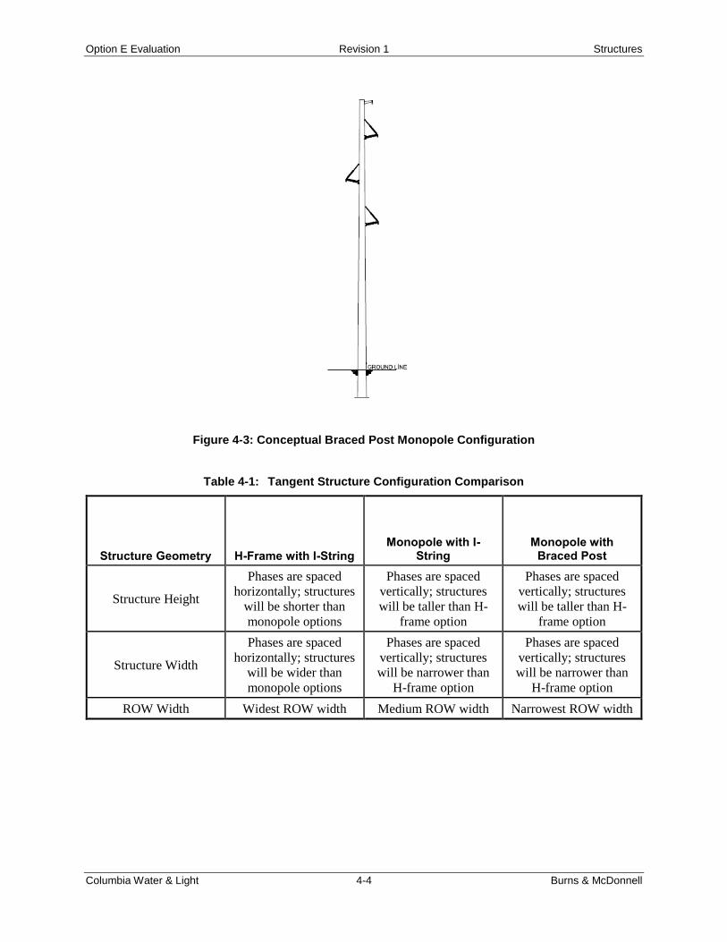
4.1.3 Monopole with Braced Posts
Monopole construction with braced post insulators have a similar phase arrangement to the I-string
insulator, but each phase wire is attached to a horizontal post insulator (See Figure 4-3). Conductors
supported by braced post insulators do not blow out as far as I-string supported wires under wind
conditions because the wire attachment location is fixed. This results in a narrower ROW width.
Because the post insulators are rigid they translate longitudinal loads due to tension imbalances to the
structure rather than swinging to relieve portions of the longitudinal load. Utilities that desire structures to
be designed for longitudinal loadings caused by broken wires on unbalanced conditions typical do not use
braced post insulators. Geometrically, the shield and phase wire arrangements are similar the TU-1
mentioned in Section 4.1.2 above.
Option E Evaluation Revision 1 Structures
Columbia Water & Light 4-4 Burns & McDonnell
Figure 4-3: Conceptual Braced Post Monopole Configuration
Table 4-1: Tangent Structure Configuration Comparison
Structure Geometry H-Frame with I-String Monopole with I-
String Monopole with
Braced Post
Structure Height
Phases are spaced
horizontally; structures
will be shorter than
monopole options
Phases are spaced
vertically; structures
will be taller than H-
frame option
Phases are spaced
vertically; structures
will be taller than H-
frame option
Structure Width
Phases are spaced
horizontally; structures
will be wider than
monopole options
Phases are spaced
vertically; structures
will be narrower than
H-frame option
Phases are spaced
vertically; structures
will be narrower than
H-frame option
ROW Width Widest ROW width Medium ROW width Narrowest ROW width

Option E Evaluation Revision 1 Structures
Columbia Water & Light 4-5 Burns & McDonnell
Structure Geometry H-Frame with I-String Monopole with I-
String Monopole with
Braced Post
Longitudinal Loads
Uses an I-string
suspension insulator
which can help reduce
longitudinal loads due
to insulator swing
Uses an I-string
suspension insulator
which can help reduce
longitudinal loads due
to insulator swing
Braced post insulators
cannot reduce
longitudinal loads or
differential tensions.
They are more prone to
failure during extreme
weather events
(increased maintenance
concern)
Structure Material Wood or steel possible Steel only Steel only
Tangent Foundation Direct embed Direct embed Direct embed
4.2 Structure Material Selection
For the structure types considered, wood and steel are two commonly used materials for structures
designed at 161-kV voltage. The following sections describe some of the benefits and drawbacks of each
material considered.
4.2.1 Wood
Wood poles have long been used by utilities as an aesthetic and cost-effective solution to transmission
line design. Wood often can be an economic choice, depending on structure heights, span lengths, and
wire loads. Wood has limitations at likely span lengths and proposed structure configurations of the
project being analyzed. The American National Standard Institute (ANSI) specifies wood poles by “pole
class”, which is related to the magnitude of horizontal load a pole can withstand without exceeding its
allowable stress. The largest class wood pole available is an “H6” which is also only available in limited
quantities with long lead times.
For the probable span lengths for this project (discussed further in Section 6.0) and assumed wire
tensions, wood vertical monopole construction is impractical, as structure loading would exceed the
allowable capacity of an H6 wood pole. The possibility of wood monopoles could be feasible if span
lengths were reduced to approximately 400 feet instead of matching the average McCredie-Overton span
lengths of 800 feet. This option would, however, double the quantity of structures required and possibly
increase the required centerline offset distance from the existing 345-kV line.

Option E Evaluation Revision 1 Structures
Columbia Water & Light 4-6 Burns & McDonnell
Classed wood poles could be a feasible and economical structure material option used for the H-frame
structure configuration. In this configuration two wood poles would support the assumed wire loads and
span lengths so a pole class smaller than H6 is likely possible and could result in cost savings over a
similar steel structure.
Due to the anticipated wire loads and structure heights, wood pole strength and available length would
preclude wood from being used for any double or triple circuit construction discussed in Section 7.0.
4.2.2 Steel
Engineered steel poles are a viable option for all three proposed structure configurations. Steel poles
allow for more flexibility in design and are not bound to the strength limitations of wood poles. Steel
generally has a longer service life than wood and is not subject to rot, woodpecker damage, or other
premature structure deterioration. Most steel pole manufacturers offer either a “classed” system of
standard poles or a custom engineered solution based on the loading and configuration provided by the
engineer. It is anticipated that all single circuit structures proposed could utilize a classed pole, however
due to the quantity of structures and expected wire loading required for the project, a custom design may
be more cost effective.
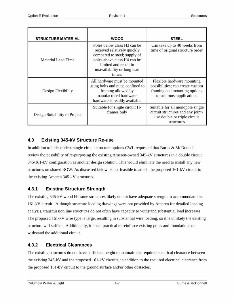
Table 4-2: Structure Material Comparison
STRUCTURE MATERIAL WOOD STEEL
Engineered product
No (variations accounted for by
additional strength reduction
factors used in design)
Yes (controlled material
strengths)
Service life
Can be affected by decay,
wildlife, and other natural
contaminants
Typically more resistant to long
term environmental effects
(especially galvanized steel)
Strength
Strength limited to properties of
natural materials. Lengths not
possible for all configurations
Can be designed and
constructed to near limitless
strength requirements
Cost
Poles below class H3 are
considered more economical
than a comparable steel pole;
poles above class H4 may not
be more economical depending
on wood availability
Cost is highly dependent on
current steel pricing when poles
are ordered
Option E Evaluation Revision 1 Structures
Columbia Water & Light 4-7 Burns & McDonnell
STRUCTURE MATERIAL WOOD STEEL
Material Lead Time
Poles below class H3 can be
received relatively quickly
compared to steel; supply of
poles above class H4 can be
limited and result in
unavailability or long lead
times.
Can take up to 40 weeks from
time of original structure order
Design Flexibility
All hardware must be mounted
using bolts and nuts; confined to
framing allowed by
manufactured hardware;
hardware is readily available
Flexible hardware mounting
possibilities; can create custom
framing and mounting options
to suit most applications
Design Suitability to Project
Suitable for single circuit H-
frames only
Suitable for all monopole single
circuit structures and any joint-
use double or triple circuit
structures
4.3 Existing 345-kV Structure Re-use
In addition to independent single circuit structure options CWL requested that Burns & McDonnell
review the possibility of re-purposing the existing Ameren-owned 345-kV structures in a double circuit
345/161-kV configuration as another design solution. This would eliminate the need to install any new
structures on shared ROW. As discussed below, is not feasible to attach the proposed 161-kV circuit to
the existing Ameren 345-kV structures.
4.3.1 Existing Structure Strength
The existing 345-kV wood H-frame structures likely do not have adequate strength to accommodate the
161-kV circuit. Although structure loading drawings were not provided by Ameren for detailed loading
analysis, transmission line structures do not often have capacity to withstand substantial load increases.
The proposed 161-kV wire type is large, resulting in substantial wire loading, so it is unlikely the existing
structure will suffice. Additionally, it is not practical to reinforce existing poles and foundations to
withstand the additional circuit.
4.3.2 Electrical Clearances
The existing structures do not have sufficient height to maintain the required electrical clearance between
the existing 345-kV and the proposed 161-kV circuits, in addition to the required electrical clearance from
the proposed 161-kV circuit to the ground surface and/or other obstacles.

Option E Evaluation Revision 1 Structures
Columbia Water & Light 4-8 Burns & McDonnell
4.3.3 System Planning
In addition to the structural integrity and clearance concerns of the existing structure, having a combined
double circuit 345/161-kV structure would need to be studied to determine the negative effects on the
system reliability. When a lower voltage circuit (e.g. 161-kV) is located on a joint-use structure with a
higher voltage circuit (e.g. 345-kV), the lower voltage can often act as a “sacrificial” circuit during a
lightning event. Because the 161-kV circuit would utilize a shorter insulator string than the 345-kV
circuit, lightning flashovers will generally be much more common on the 161-kV circuit, resulting in
increased outages over a typical single circuit 161-kV transmission line.

Option E Evaluation Revision 1 Proposed Corridor
Columbia Water & Light 5-1 Burns & McDonnell
5.0 PROPOSED CORRIDOR
In areas where the proposed Option E is adjacent to the existing McCredie-Overton 345-kV circuit, two
horizontal distances must be calculated to determine the additional ROW width required and the proposed
161-kV centerline location; the required centerline offset between the existing 345-kV circuit and
proposed 161-kV circuit and the distance from the proposed 161-kV circuit to the edge of the proposed
ROW.
5.1 345-kV to 161-kV Spacing
The Ameren Report, discussed in Section 2.1, offered two conclusions regarding the centerline of the
proposed 161-kV circuit:
1. 69 feet from the centerline of the 345kV transmission line to any part of the structure supporting
a 161-kV transmission line.
2. 71 feet from the centerline of the 345kV transmission line to any wire attachment point for a 161-
kV transmission line.
Based on a discussion with Ameren, these statements assume that the proposed 161-kV structures are to
be located at midspan of the existing 345-kV structure locations, resulting in the most conservative
(largest) offset assumption due to wire blowout considerations. During detailed design, these offset
requirements could likely be reduced based on actual design information or by spotting the proposed 161-
kV structure at locations immediately adjacent to the existing 345-kV structures.
5.2 161-kV to Edge of ROW
The required distance from the center of the proposed 161-kV line to the edge of ROW is dependent on
structure configuration, conductor type, conductor tension, and conductor blowout. For the purpose of
determining ROW width, two wind conditions were considered, a 48 MPH wind (6psf; NESC
requirement) and 90 MPH wind (20.7 psf; NESC condition), to calculate the required ROW width. It is
common industry practice to maintain the horizontal clearance associated with a building at the edge of
the ROW with the conductor blown out under a 48 MPH wind. For the 90 MPH wind case, many utilities
will require a small clearance often (0’ to 3’) between the blown-out wire position and edge of ROW. For
this analysis, the 48 MPH wind condition controlled the minimum ROW width requirement.

Option E Evaluation Revision 1 Proposed Corridor
Columbia Water & Light 5-2 Burns & McDonnell
As referenced in Section 5.0, each unique structure configuration will result in ROW width requirements,
due to geometry and insulator differences. Table 5-1 summarizes the minimum additional ROW width (in
addition to the re-use of the existing 150’ 345-kV ROW) required by structure type Figure 5-1 exhibits
the same information.
.
Table 5-1: Minimum Additional ROW Width Required
H-Frame I-string Delta Monopole
I-string Delta Monopole
Braced Post
ROW
width
(ft)
52’ 40’ 31’

Option E Evaluation Revision 1 Proposed Corridor
Columbia Water & Light 5-3 Burns & McDonnell
Figure 5-1: Minimum Additional ROW Width Required

Option E Evaluation Revision 1 Structure Spotting
Columbia Water & Light 6-1 Burns & McDonnell
6.0 STRUCTURE SPOTTING
In general, the intent of structure spotting is to attempt to minimize the total structure quantity and heights
(cost considerations), while meeting the design requirements of the project (code and client requirements)
and minimizing impact to adjacent landowners, the environment and project constraints (land use
impacts). Structure spotting can be constrained by many factors such as: environmental, public
involvement, archeological, among others. When attempting to route a line within an existing
transmission corridor (as approximately 75% of Option E is), spotting adjacent to existing structures
generally results in the narrowest required ROW. Additionally, structures positioned next to each other in
a corridor is preferred aesthetically over structures spotted at mid span relative to the existing line.
Although detailed line spotting for the proposed 161-kV line was not performed as part of the scope of
this analysis, Burns & McDonnell reviewed the spotting of the existing 345-kV circuit to examine the
feasibility of spotting new structures adjacent to the existing 345-kV structures. Based on the existing line
spotting, the average span of a future 161-kV line would be approximately 800’ in length, which is
considered reasonable for a 161-kV circuit.
Option E Evaluation Revision 1 Corridor Constraints
Columbia Water & Light 7-1 Burns & McDonnell
7.0 CORRIDOR CONSTRAINTS
Based on the Ameren Report and a high-level review of the proposed route by Burns & McDonnell, it
was determined that Option E has several areas with corridor constraints due to existing infrastructure.
Although there are feasible design solutions for each of the noted areas, there will be additional cost
impacts for each of the solutions. The following sections summarize some of the key areas of interest and
possible design solutions in these areas. Each section has been assigned a region number which
corresponds to route map in Appendix A.
7.1 Bolstad Substation Area (Region 1)
From the intersection of Peabody Road and Brown Station Road eastward to Bolstad Substation, the
proposed route is currently congested with existing overhead utilities. Based on a review of publicly
available data, this corridor appears to contain three distribution circuits and two 69-kV circuits. To
create room for the proposed 161-kV circuit, CWL staff suggested relocating the three distribution
circuits underground to create room for the proposed circuit. Burns & McDonnell agrees with this
approach.
7.2 Brown Station Road to Highway 63 (Region 2)
The Ameren Report mentions a double circuit distribution line on south side of the existing ROW
between Ameren structures 623 and 643. It appears that the referenced line is a single circuit 69-kV line
from Brown Station Road until approximately North Oakland Gravel, where a second 69-kV line joins.
The existing structures are double circuit 69-kV until approximately Missouri Highway 63 where both
69-kV lines deviate from the Ameren ROW.
Starting at Brown Station Road and heading west until passing the Columbia COLT Terminal, the
existing 69-kV circuit could be removed and placed on new double circuit 161/69-kV structures.
Alternatively, for this segment of the proposed route, the new 161-kV circuit could be placed on the north
side of the ROW until North Oakland Gravel Road. The line would have to cross underneath the existing
Ameren 345-kV line in at least two locations. These crossings would require Ameren cooperation, the
replacement of approximately four existing Ameren-owned 345kV structures, additional 161-kV angle
structures near the crossings, and the possible reliability concern of a wire dropped from the existing 345-
kV circuit taking the proposed 161-kV circuit out of service. Offsetting the line to the north side of the
ROW in this segment of line would be much costlier than rebuilding the existing 69-kV circuit on a joint-
use structure.

Option E Evaluation Revision 1 Corridor Constraints
Columbia Water & Light 7-2 Burns & McDonnell
Approximately 0.25 miles east of North Oakland Gravel Road, additional ROW width is not available due
to a second 69-kV circuit in the corridor and the beginning of residential dwellings. From this point
westward until Highway 63, the existing ROW contains the existing Ameren 345-kV line and an existing
double circuit 69/69-kV line, one circuit owned by the City of Columbia and the other by Central Electric
Power Cooperative (CEPC). Both the north and south sides of the ROW have residential dwellings along
the current corridor and would not allow an expanded ROW to include the new 161-kV line. To utilize
existing ROW, the two 69-kV circuits could be removed and replaced on new triple circuit 161/69/69-kV
structures. This would require both the cooperation of CEPC and extensive outage planning, as well as
more complex structure loading and unique designs.
7.2.1 Combined 345/161-kV Structure
An alterative to rebuilding the existing 69-kV circuits in this area, the existing 345-kV circuit could be
rebuilt onto a new joint-use double circuit 345/161-kV structure. This option would require the Ameren
345-kV line to take an outage so that the existing structures in this two-mile area could be demolished and
new double circuit structures built. It is unlikely that Ameren would desire to take such an outage.
Additionally, the cost to construct this option would likely exceed the cost of rebuilding the 69-kV
circuits in the corridor since the required structure and foundation sizes would be much larger and
structures taller than the option presented in Section 7.2.
7.3 North Creasy Springs to North O Neal Road (Region 3)
Starting just east of North Creasy Springs Road to just west of North O Neal Road, there are line has
several houses immediately adjacent to the edge of the existing 345-kV ROW. Using a vertical
configuration 161-kV structure (narrowest possible option) on south side of the 345-kV line, the corridor
is not wide enough to accommodate both circuits. Routing the line to the north side of the 345-kV line
would result in similar situation with the added cost of having to raise approximately four 345-kV
structures. Two possible options are offered below.
7.3.1 Double Circuit 345/161-kV
One option would include taking a temporary 345-kV outage while approximately one mile of Ameren’s
existing line is removed and rebuilt with joint-use, double circuit 345/161-kV, vertical configuration
structures. This would require Ameren’s cooperation, scheduling of an outage and system planning
studies. One of the largest drawbacks of this option would be the increased cost associated with very large
joint use structures. The electrical performance of the line will also need to be analyzed to ensure
acceptable performance is obtained in the lower voltage 161-kV circuit. These joint use structures would

Option E Evaluation Revision 1 Corridor Constraints
Columbia Water & Light 7-3 Burns & McDonnell
likely be very tall and visually intrusive in comparison with the existing 345-kV structures. The
structures would need to be located on drilled shaft foundations.
7.3.2 Property Acquisition
Another option for this segment would involve purchasing the adjacent property and buildings and
expand the ROW to construct and maintain a new circuit adjacent to the existing Ameren line. To
determine the number of impacted buildings and parcels a detailed survey would need to be completed
and detailed line design would need to be performed. Depending on the relative cost of the land
acquisition and public relations concerns, this may another viable option in this segment.
7.4 Ameren Structure 679 (Region 4)
Approximately 0.5 miles south of the intersection of North Moreau Road and West Driskel Road, near
Ameren structure 679 is a parcel that contains an existing metal building near the edge of the existing
ROW. This building would be directly under the proposed 161-kV circuit. During detailed design, the
161-kV line could be analyzed to determine if the centerline can be moved closer to 345-kV line for this
segment. If the proposed 161-kV line cannot be offset closer to the existing 345-kV circuit enough to
provide clearance to the building, the existing building may need to be relocated or removed.
Another option to avoid this obstruction would include crossing to the opposite side of the existing 345-
kV circuit. Based on discussions with the CWL, alternating the location of the proposed 161-kV route
back and forth relative to the existing 345-kV route is undesirable and should be avoided if possible. It is
doubtful that there would be any cost savings in crossing to the alternate side of the corridor compared to
relocating or removing the building, as existing 345-kV structures would likely need to be rebuilt to
accommodate the required crossing clearances.
7.5 Perche Creek Crossing Area (Region 5)
Option E crosses Perche Creek near the Breckenridge Park subdivision that is currently under
construction. As a possible way to avoid visual or land impacts, Option E could be routed further west
through this area. It should also be noted that based on publicly available data, on page 2 of Breckenridge
Park Plat No. 1, a 110-foot future ROW for the extension of West Broadway is reserved. During final
design it would be recommended to coordinate with appropriate departments to spot structures out of
future roadway.

Option E Evaluation Revision 1 Corridor Constraints
Columbia Water & Light 7-4 Burns & McDonnell
7.6 Perche Creek Substation Area (Region 6)
Option E turns east approximately 0.75 miles west of Perche Creek Substation, from this turn into the
substation the corridor contains an existing CWL 161-kV wood pole H-frame line. Residential dwellings
border the proposed route on both sides of the centerline with no room to expand the ROW. If the
proposed entrance route to the substation is utilized, the existing 161-kV line would have to take an
outage, be removed and rebuilt onto a double circuit, vertical phase configuration structure. Reuse of the
existing wood poles would not be possible for similar reasons discussed in Section 4.3.

Option E Evaluation Revision 1 Acreage Impact
Columbia Water & Light 8-1 Burns & McDonnell
8.0 ACREAGE IMPACT
Using the parcel data provided by CWL, an acreage impact analysis was performed. This analysis was
based on the assumptions from Section 5.0 and Table 5-1. Option E affected 94 parcels, the details are
shown in Table 8-1. Table 8-2 was provided entirely by and for the benefit of CWL.
Table 8-1: Acreage Impact of Additional ROW required
Land Use Category Acreage
Agricultural 5.7
Church 0.1
Commercial 0.4
Driveway 0.1
Forested 25.7
Industrial 1.7
Pasture/Grassland 38.3
Pond 0.4
Recreational 1.4
Residential 8.9
Stream 0.2
Substation 0.3
Total 83.2

Option E Evaluation Revision 1 Acreage Impact
Columbia Water & Light 8-2 Burns & McDonnell
Table 8-2: Acreage Impact by Zone
District Zone Acreage
IG City 1.66889
M-BP City 0.332443
PD City 0.699123
R-1 City 10.469
County 3.297172
A-1 County 6.206549
A-2 County 27.37848
A-R County 19.77103
R-M County 4.450339
R-S County 8.591924
REC County 3.687325

Option E Evaluation Revision 1 Summary
Columbia Water & Light 9-1 Burns & McDonnell
9.0 SUMMARY
Burns & McDonnell has analyzed the feasibility of the proposed Option E, which parallels the existing
Ameren-owned McCredie-Overton 345-kV transmission line for the majority of the route, as directed by
the CWL. Based on the project information received and analyzed, Burns & McDonnell believes that the
proposed route is feasible, although there are a number of route obstructions which will need to be
addressed and will ultimately have additional costs that would not be recognized from an unobstructed
route. The westerly portion of the route, parallel to the existing 345-kV circuit, provides an economical
unobstructed route. However, the eastern half of the proposed route has several obstructions that may
benefit from diverging from the existing corridor and re-routing the line elsewhere to minimize cost
impacts
For the proposed route, Burns & McDonnell would recommend a typical steel I-string monopole with
delta phase configuration in areas not constrained by ROW, existing utilities, or other obstructions.
Because ROW constraints are common throughout the proposed corridor, the additional easement width
required from the use of an h-frame type structure may not be practical for this application. Wood is often
recognized as an economical structure material for transmission lines, but for the assumptions used as part
of this project, standard wood monopoles do not have the required strength capacity to support the wire
types, design loads, and span lengths required for this application. Additionally, Burns & McDonnell
recommends the use of I-string insulators as opposed to braced post insulators, to allow for the relief of
longitudinal loads and the expectation of reduced maintenance and repair during extreme weather events.

- OPTION E MAP

COPY
RIGH
T © 20
18 B
URNS
& M
cDON
NELL
ENGI
NEER
ING
COMP
ANY,
INC.
Source: USDA NAIP 2016 Aerial Photography; TIGER Roads; Burns & McDonnell. May 03, 2018
Path:
\\bmc
d\dfs\
Clien
ts\TN
D\Co
lumbia
MO\10
4146
_Rou
teEev
al\St
udies
\Geo
spati
al\Da
taFile
s\ArcD
ocs\C
olumb
ia_Wa
ter_a
nd_L
ight_O
ption
_E_R
egion
s.mxd
rfra
ser
5/3/20
18
Columbia Water & LightOption E
Sheet 1 of 4
")Bolstad Substation
N Oa
kland
Gra
vel R
d
Brow
n Stat
ion Rd
Peabody Rd
Region 2Region 1
£¤63£¤63
")B
")HH
NORTH
0 2,0001,000Feet
LEGEND") Existing Substation
Proposed RouteSee Section 7 of report for informationregarding region numbers.

COPY
RIGH
T © 20
18 B
URNS
& M
cDON
NELL
ENGI
NEER
ING
COMP
ANY,
INC.
Source: USDA NAIP 2016 Aerial Photography; TIGER Roads; Burns & McDonnell. May 03, 2018
Path:
\\bmc
d\dfs\
Clien
ts\TN
D\Co
lumbia
MO\10
4146
_Rou
teEev
al\St
udies
\Geo
spati
al\Da
taFile
s\ArcD
ocs\C
olumb
ia_Wa
ter_a
nd_L
ight_O
ption
_E_R
egion
s.mxd
rfra
ser
5/3/20
18
Columbia Water & LightOption E
Sheet 2 of 4
Region 3
Region 2
N Cr
easy
Spr
ings R
d
£¤63
£¤63
¬«763
")VV
NORTH
0 2,0001,000Feet
LEGEND") Existing Substation
Proposed RouteSee Section 7 of report for informationregarding region numbers.

COPY
RIGH
T © 20
18 B
URNS
& M
cDON
NELL
ENGI
NEER
ING
COMP
ANY,
INC.
Source: USDA NAIP 2016 Aerial Photography; TIGER Roads; Burns & McDonnell. May 03, 2018
Path:
\\bmc
d\dfs\
Clien
ts\TN
D\Co
lumbia
MO\10
4146
_Rou
teEev
al\St
udies
\Geo
spati
al\Da
taFile
s\ArcD
ocs\C
olumb
ia_Wa
ter_a
nd_L
ight_O
ption
_E_R
egion
s.mxd
rfra
ser
5/3/20
18
Columbia Water & LightOption E
Sheet 3 of 4
N O'
Neal
Rd
W Driskel Rd
N Mo
reau R
d
Region 3
Region 4
")E
NORTH
0 2,0001,000Feet
LEGEND") Existing Substation
Proposed RouteSee Section 7 of report for informationregarding region numbers.

COPY
RIGH
T © 20
18 B
URNS
& M
cDON
NELL
ENGI
NEER
ING
COMP
ANY,
INC.
Source: USDA NAIP 2016 Aerial Photography; TIGER Roads; Burns & McDonnell. May 03, 2018
Path:
\\bmc
d\dfs\
Clien
ts\TN
D\Co
lumbia
MO\10
4146
_Rou
teEev
al\St
udies
\Geo
spati
al\Da
taFile
s\ArcD
ocs\C
olumb
ia_Wa
ter_a
nd_L
ight_O
ption
_E_R
egion
s.mxd
rfra
ser
5/3/20
18
Columbia Water & LightOption E
Sheet 4 of 4
") Perche Creek Substation
Scott
Blvd
Region 6
Region 5
§̈¦70 §̈¦70£¤40
")UU
")E
NORTH
0 2,0001,000Feet
LEGEND") Existing Substation
Proposed RouteSee Section 7 of report for informationregarding region numbers.

Burns & McDonnell World Headquarters 9400 Ward Parkway
Kansas City, MO 64114 O 816-333-9400 F 816-333-3690
www.burnsmcd.com