16023083 -...
114
Transcript of 16023083 -...

mduckw
mduckw
16023083

mduckw
16023083

16023083© 1996 Maytag Corporation
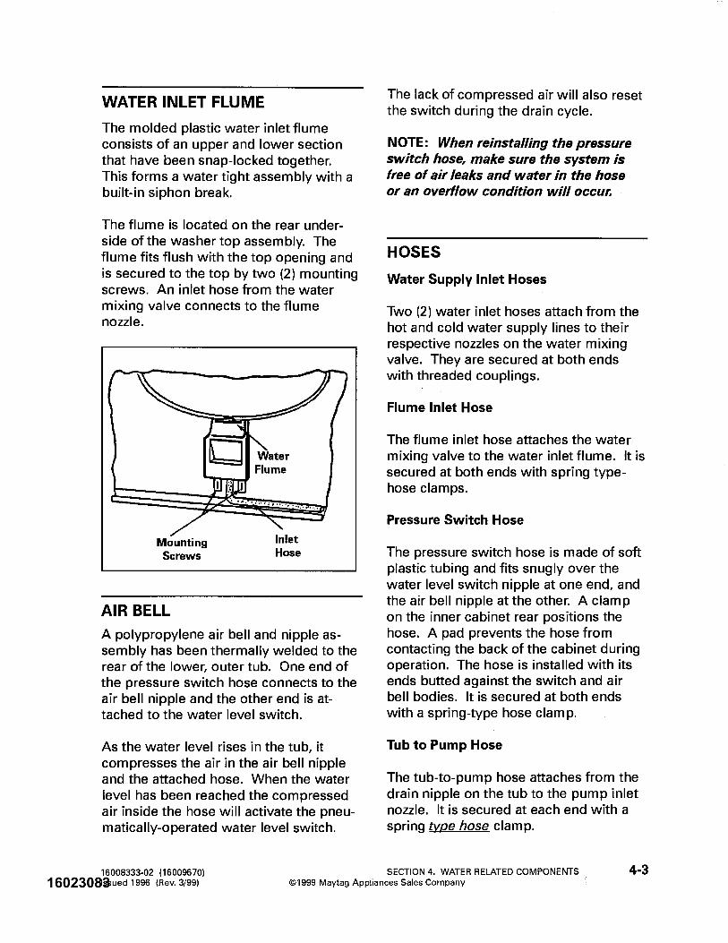
INTRODUCTION
The information presented in this manual is printed in a loose format and is divided intosections relating to a general group of components and/or service procedures. Eachsection is further subdivided to describe a particular component or service procedure.
Anything of a unique nature concerning these models has been detailed and labeled assuch in the manual.
The subdividing of the subject matter, plus the loose leaf form will facilitate the updat-ing of the manual as new or revised components are added or new models are intro-duced.
Each page of the manual will be identified in the lower right-hand corner, and as new orrevised pages are published, the manual can easily be updated by following the fileinstructions on the cover letter of the supplement.
The service manual is a valuable tool and care should be taken to keep it up to date byprompt and proper filing of subsequent pages as they are used.
MODELS COVERED IN THIS MANUAL
PAV1000AW*PAV2000AW*
INTRODUCTION i
DLW231*PAV2300*PAV3300*PAV5000*PAV5157*PAV5158*
PAVT344*HAV2460*PAVT244*PAVT234*HAV2360*MAV2200*HAV2557*HAV2558*HAV3460*PAVT444*HAV4657*

16023083© 1996 Maytag Corporation
INTRODUCTION ii

16023083© 1996 Maytag Corporation
CONTENTS iii
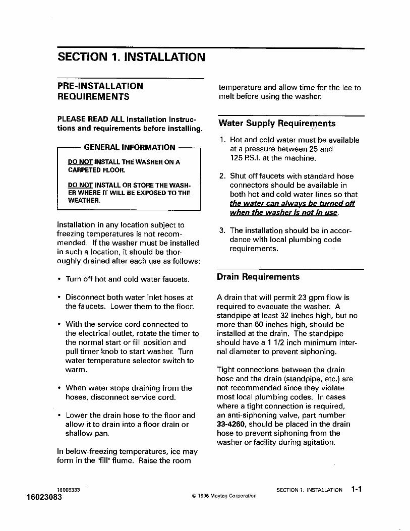
SECTION 1. INSTALLATION ............................................................... 1-1PRE-INSTALLATION REQUIREMENT .......................................................................... 1-1
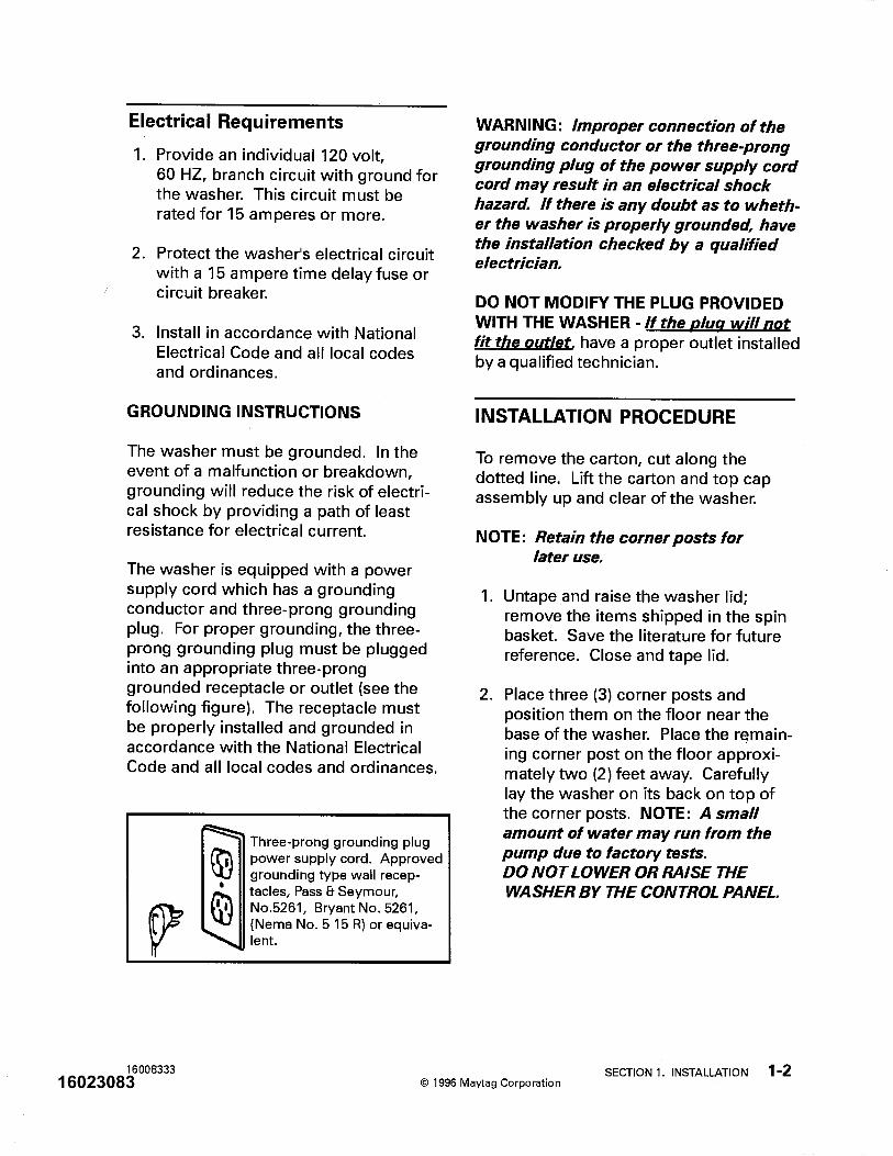
Water Supply Requirements .................................................................................. 1-1Drain Requirements................................................................................................ 1-1Electrical Requirements.......................................................................................... 1-2
INSTALLATION PROCEDURE...................................................................................... 1-2
SECTION 2. OUTLINE OF MECHANICAL OPERATION ................... 2-1CLUTCH ASSEMBLY ................................................................................................... 2-1AGITATION .................................................................................................................. 2-2SPIN ............................................................................................................................. 2-2
SECTION 3. CABINET ASSEMBLY COMPONENTS ......................... 3-1CABINET BODY ASSEMBLY ...................................................................................... 3-1
Front Panel ............................................................................................................. 3-1Rear Access Panel ................................................................................................. 3-2
TOP ASSEMBLY.......................................................................................................... 3-3DOOR ASSEMBLY ...................................................................................................... 3-4CONTROL PANEL ASSEMBLY (PAV1000AWW, PAV2000AWW) ............................ 3-4
Disassembly ........................................................................................................... 3-4CONTROL PANEL ASSEMBLY (PAV2200, 3200, 4200) ............................................. 3-6
Disassembly ........................................................................................................... 3-6BASE ASSEMBLY ....................................................................................................... 3-8STABILIZER ASSEMBLY ............................................................................................. 3-9
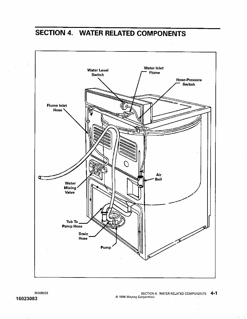
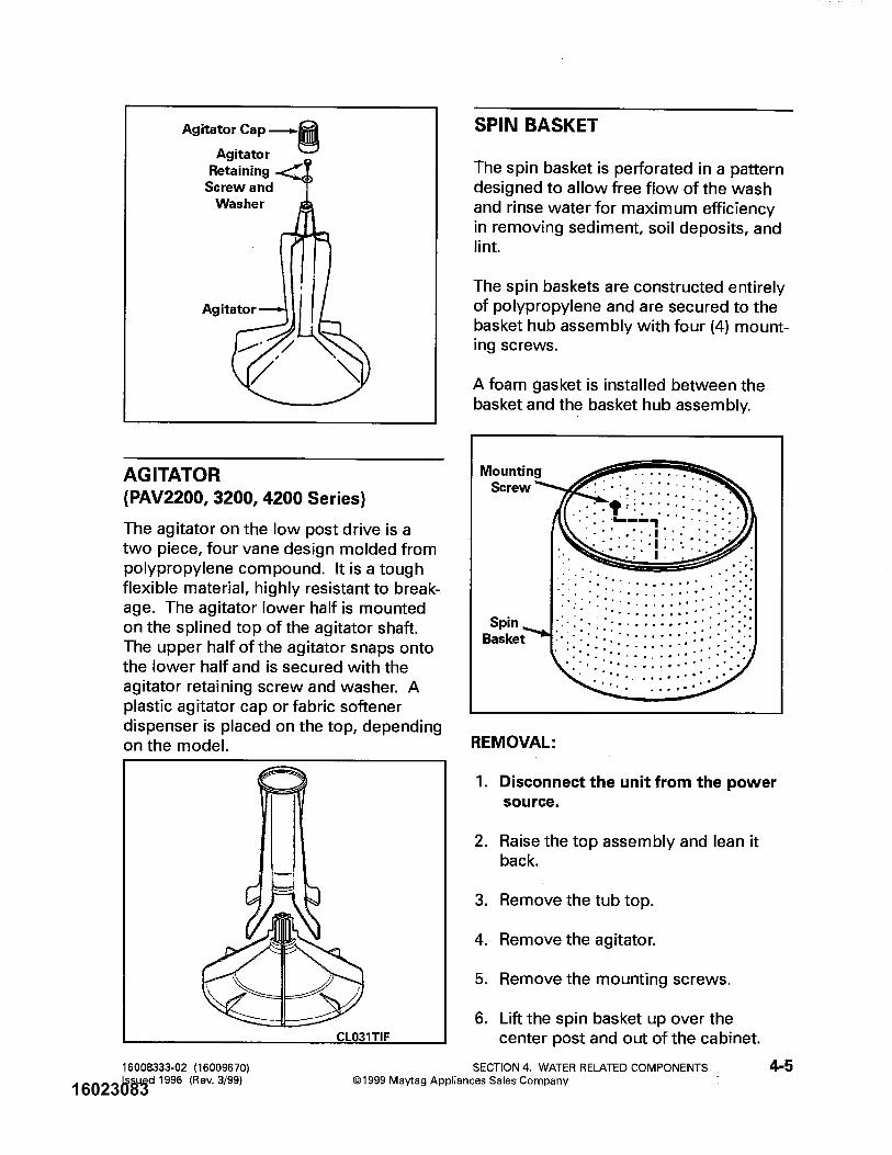
SECTION 4. WATER RELATED COMPONENTS ................................ 4-1WATER MIXING VALVE .............................................................................................. 4-2WATER INLET FLUME.................................................................................................. 4-3AIR BELL ...................................................................................................................... 4-3HOSES......................................................................................................................... 4-3TUB TOP ...................................................................................................................... 4-4AGITATOR (PAV1000AWW, PAV2000AWW) ............................................................ 4-4AGITATOR (PAV2200, 3200, 4200)............................................................................. 4-5SPIN BASKET .............................................................................................................. 4-5OUTER TUB ASSEMBLY ............................................................................................. 4-6PUMP ASSEMBLY ....................................................................................................... 4-7
SECTION 5. SUSPENSION SYSTEM (PAV1000AWW, PAV2000AWW) ...5-1SUSPENSION SYSTEM (PAV2200, 3200, 4200) ........................................................ 5-2SUSPENSION HOUSING ............................................................................................. 5-3TUB BRACES............................................................................................................... 5-3SUSPENSION SPRINGS.............................................................................................. 5-3
CONTENTS

16023083© 1996 Maytag Corporation CONTENTS iv
SECTION 6. TRANSMISSION AND RELATED COMPONENTS ........ 6-1CENTER POST ASSEMBLY ........................................................................................ 6-2BEARING AND SEAL HOUSING .................................................................................. 6-2TUB SEAL .................................................................................................................... 6-3SPIN BEARING............................................................................................................. 6-4DRIVE PULLEY AND CAMS ........................................................................................ 6-5BRAKE ASSEMBLY ..................................................................................................... 6-8TRANSMISSION HOUSING ASSEMBLY..................................................................... 6-10
Oil Seal Replacement ............................................................................................ 6-11LOWER BEARING ASSEMBLY .................................................................................. 6-11DIAGNOSING TRANSMISSION PROBLEMS ............................................................. 6-13
SECTION 7. ELECTRICAL COMPONENTS AND TESTING .............. 7-1TIMER........................................................................................................................... 7-1TIMER SEQUENCE CHART ......................................................................................... 7-2MOTOR ........................................................................................................................ 7-3MOTOR SWITCH ........................................................................................................ 7-3MOTOR MOUNTING .................................................................................................... 7-6MOTOR CIRCUIT TESTING ......................................................................................... 7-7
Overload Protector ................................................................................................ 7-7Motor Switch ........................................................................................................... 7-8Motor ...................................................................................................................... 7-8
WATER MIXING VALVE .............................................................................................. 7-8WATER LEVEL SWITCH .............................................................................................. 7-9SELECTOR SWITCHES ............................................................................................. 7-11SAFETY SPIN SWITCH ............................................................................................. 7-11
SECTION 8. SCHEMATIC DIAGRAM................................................... 8-1
SECTION 9. TROUBLESHOOTING...................................................... 9-1

16023083© 1996 Maytag Corporation
SAFETY NOTES
PRECAUTIONS TO BE OBSERVED BEFORE AND DURING SERVICING TO AVOIDPOSSIBLE EXPOSURE TO EXCESSIVE DANGER AND ELECTRICAL SHOCK:
1. Disconnect electrical supply before servicing machine.2. If electricity is required for a test:
(A) First, disconnect electrical supply;
(B) Second, make any connections or adjustments required for the test;
(C) Third, connect electrical supply;
(D) Fourth, perform the test. If service is required, disconnect electrical supply before servicing machine.
3. Please use caution when servicing the machine with the front panelremoved because there is danger of injury due to potential contactwith spinning transmission.
4. Please use caution when servicing the machine with the front panelremoved because there is danger of injury due to contact with apotential "pinch point" between the turned up edge of the transmissioncover and the tub support flange.
SAFETY NOTES v

16023083© 1996 Maytag Corporation
SAFETY NOTES vi

16023083© 1996 Maytag Corporation
WASHER WEIGHT
Shipping - 185 pounds approximatelyOperating - 160 pounds approximately
DIMENSIONS
Width 27" Depth 27"
Height to top of cabinet 35 3/4"Height to top of control panel 44"Height with door open 53 1/2"
FINISH
Cabinet Top - powdered paintClothes Door - powdered paintOuter Tub - constructed entirely of polypropyleneBasket - polypropyleneCabinet - baked enamelBase and other finished parts - baked primer
DRAIN HEIGHT
32 inch minimum60 inch minimum
MOTOR
3/4 H.P., reversible, 115 volt, 60 cycle A.C.
TRANSMISSION
Rack and pinion type, incorporating reduction gears
SPECIFICATIONS
SPECIFICATIONS Vii

16023083© 1996 Maytag Corporation
WATERCYCLE LEVEL *AMPSAgitate-Regular Full Tub 10.4Agitate-Slow Full Tub 7.6Agitate-Regular Dry Tub 7.5Spin-Regular Dry Tub 10.2Spin-Slow Dry Tub 7.6Pump Out-Regular Full Tub 10.8Pump Out-Slow Full Tub 8.0
Setting Gallons *Depth *Basket Inches Perforations
Mini 10.5 6" 3 1/2"Medium 14.1 8 1/2" 5"High 19.5 11" 7"Super 23.3 13 1/2" 9 1/4"
*Allowable variations are plus or minus 1/2 inch.
AGITATOR SPEED
Regular Cycle 90 Oscillations per minute Slow (Delicate) Cycle 60 Oscillations per minute
SPIN SPEED
Regular Cycle 625 R.P.M. Slow (Fine Wash) Cycle 416 R.P.M.
SPECIFICATIONS viii
*WATTAGECYCLE RANGE
Agitate-RegularFull Tub 610-640 / 670 (MAX.)
Agitate-SlowFull Tub 370-400 / 420 (MAX.)
Agitate-RegularDry Tub 460-470 / 480 (MAX.)
Agitate-SlowDry Tub 350-360 / 370 (MAX.)
Pump Out-Regular 760
Pump Out-Slow 510
Spin-RegularFull Tub 460
Spin-SlowFull Tub 340
* These will vary with washer load and line voltage.
TABLE 0-1. AMPERAGE CHART TABLE 0-2. RESISTANCE CHART
TABLE 0-2. RESISTANCE CHART
*RESISTANCECOMPONENTS (OHMS)Timer Motor 2360Mixing ValveCold Solenoid 853Hot Solenoid 867
Drive MotorHigh Speed 1.3Low Speed 2.3Start 3.1
* These values can vary slightly.

16023083© 1996 Maytag Corporation
SPECIAL TOOLSAll special tools are manufactured by Robinaire with the exception of the 35-2442 Brake Removal Tooland 35-2968 Spanner Wrench - Basket Hub. These tools are privately manufactured for and stockedby Maytag Customer Service.
NOTE: The tools listed below can be ordered from any authorized Maytag Customer Service partsdistributor.
Transmission Seal Tool, Part Number 14242
Spring Tool Kit, Part Number 21001138
Motor Test Cord, Part Number 038183Spanner Wrench-Basket Hub, Part Number 35-2968
Brake Removal Tool, Part Number 35-2442
SPECIAL TOOLS ix

16023083© 1996 Maytag Corporation
SPECIAL TOOLS x
mduckw
mduckw
16023083
mduckw
mduckw
16023083

mduckw
mduckw
16023083

mduckw
mduckw
16023083

mduckw
mduckw
16023083

mduckw
mduckw
16023083

mduckw
mduckw
16023083
mduckw
mduckw
16023083

mduckw
mduckw
16023083

mduckw
mduckw
16023083

mduckw
mduckw
16023083

mduckw
mduckw
16023083

mduckw
mduckw
16023083

mduckw
mduckw
16023083

mduckw
mduckw
16023083

mduckw
mduckw
16023083

mduckw
mduckw
16023083

mduckw
mduckw
16023083
mduckw
mduckw
16023083

mduckw
mduckw
16023083
mduckw
mduckw
16023083

mduckw
mduckw
16023083
mduckw
mduckw
16023083

mduckw
mduckw
16023083

mduckw
mduckw
16023083

mduckw
mduckw
16023083

mduckw
mduckw
16023083

mduckw
mduckw
16023083

mduckw
mduckw
16023083

mduckw
mduckw
16023083

16023083© 2004 Maytag ServicesSECTION 6. TRANSMISSION AND RELATED COMPONENTS 6-1
SECTION 6. TRANSMISSION AND RELATEDCOMPONENTSThis section will detail the servicing procedures on the transmission assembly whichhas splines formed on the agitator drive shaft. An "O" ring is installed on the shaft justabove the center post to provide a center post seal when the agitator is installed.

16023083© 2004 Maytag ServicesSECTION 6. TRANSMISSION AND RELATED COMPONENTS 6-2
CENTER POST ASSEMBLY
The center post assembly consists of aplastic center post. A nylon agitatorbearing slips over the lower portion onthe center post body.
The center post assembly is secured tothe basket hub assembly by the spinbasket, and to the agitator shaft. Asmall rubber gasket is installed in agroove on the bottom flange of the centerpost, and a foam gasket is placedbetween the bottom of the spin basketand the basket hub assembly.
The center post can be removed afterremoving the spin basket, and the agita-tor shaft "O" ring.
The die-cast bearing and seal housingslips over a machined area on the lowerdrive tube. The basket hub assemblythreads downward over the drive tubeand secures the bearing and seal hous-ing.
The spin bearing and the tub seal areinstalled in a cavity in the center of thehousing. The sheet metal tub support isattached to the under side of the housingwith three (3) mounting screws. Thespin bearing has been pressed into theunderside of the housing cavity and issecured by the tub support.
The center of the tub assembly mounts tothe upper flange of the housing with a tubgasket and a tub seal installed between.The bottom of the tub sits on, and isattached to, the tub support.
BEARING AND SEAL HOUSING
REMOVAL:
1. Disconnect the unit from the powersource.
2. Remove the agitator, spin basket,tub assembly, and center post.
3. Remove the Seal nut with 2202898 and35-2968
4. Remove the basket hub assemblyby turning it in a counterclock-wise direction, using tool number35-2968.
5. Remove the suspension springs toprevent damage to the tub bracesand unbolt the tub braces from thetub support.
6. To remove, lift up on the bearingand seal housing with tub supportattached.
7. To disassemble tub support fromhousing, remove mounting screwsfrom underside.

16023083© 2004 Maytag ServicesSECTION 6. TRANSMISSION AND RELATED COMPONENTS 6-3
TUB SEALThere are 2 Tub Seal designs, the originalFace Seal and the new Triple Lip Sealintroduced at series 17.
Face SealThe tub Face Seal consists of the seal faceand seal body.
NOTE: All parts of the seal must bereplaced if either of the sealing surfacesare damaged.
The seal face fits into a recess in the under-side of the basket hub assembly. Also, theseal body installs in the cavity on the top sideof the bearing and seal housing. The spinbearing is located in a cavity on the under-side of the bearing and seal housing.
Each of the two (2) sealing parts, the sealface and the seal body, have sealing faceswhich are brought into contact with oneanother when the basket hub assembly isthreaded down on the drive tube. Thesprings in the seal body exert pressure tokeep the sealing faces in contact.
Triple Lip Seal Triple Lip Tub Seal
Assembly used with the21001867 Hi-TorqueTransmission Assembly.
NOTE: Sealing surfaceare on the O.D. of thealuminum spinner hubwith no seal in the hubcavity.
NOTE: The Triple Lip Seal and Bearing is only used with the High Torque Dual Drive transmission. The 21001867 High Torque service transmission will include a Triple Lip Seal and Bearing for proper matching of parts. The High Torque transmission will have An “HT” next to the date code for field identification purposes. Do not use 21001868 Seal kit on older transmissions not de signed to operate at higher torque levels. Always refer to Parts Pro or Microfiche for proper parts ordering. The 21001868 Triple Lip Seal kit will include a sticker to be placed on the Outer Tub of the washer to identify the washer has been modified with a High Torque Transmission and Triple Lip Seal kit.
SealBody
SealFace

16023083© 2004 Maytag ServicesSECTION 6. TRANSMISSION AND RELATED COMPONENTS 6-4
TUB SEAL REPLACEMENT:
Should the tub seal begin to leak or developexcess seal drag, it must be replaced. Theservice replacement seal includes all theparts necessary to replace the entire seal.Be sure to replace all parts of the seal even ifonly one part is found to be damaged.
NOTE: If the tub seal is being replacedbecause it has begun to leak, the spinbearing is probably defective also andshould be replaced. To replace the spinbearing, the bearing and seal housingmust be removed as previously de-scribed. This also allows access to thetub seal for removal and replacement(refer to steps 2 and 3 below when in-stalling).
Removal and replacement of the tub sealcan ONLY be accomplished as follows:
1. Follow steps 1 through 3 for theface seal
NOTE: For Triple Lip Seal special instuction,see next column
FACE SEAL 2. Before installing the new seal, coat
the mounting recess of the housingswith silicone grease (part number203959). This will allow the sealbody and seal face to slip into posi-tion.
NOTE: MAKE SURE NO GREASECOMES IN CONTACT WITH THEMATING SURFACES OF THE SEAL.
SPIN BEARINGThe spin bearing is installed in a cavity onthe underside of the bearing and sealhousing. It is also press fitted and bot-toms out on the cavity shoulder. It isfurther secured in place by the innerdiameter of the tub support.
SPIN BEARING REPLACEMENT:
1. Disconnect the unit from the powersource.
2. Remove the bearing and seal hous-ing and the tub support as previ-ously described.
3. Remove the seal body from thehousing cavity.
4. Press the spin bearing out ofthe cavity from the opposite side ofthe housing.
5. When installing the replacementbearing into the housing cavity, besure to press against the outer raceof the bearing to avoid damage tothe bearing shield and causing pre-mature failure.
Triple Lip Seal (056016) grease
NOTE: Do not use any agent other thanalcohol to clean the mating surface. Donot use any lubricant other than SiliconeGrease, part number 203959.
3. Make sure both seal mating surfacesare free of foreign matter, then cleanboth surfaces with an alcohol satu-
rated cloth.
TRIPLE LIP SEAL 1. Apply center seal grease (056016) to
Seal Nut and Triple Lip Seal beforeinstalling.
Seal Nut (056016) grease

16023083© 2004 Maytag ServicesSECTION 6. TRANSMISSION AND RELATED COMPONENTS 6-5
onto the bottom of the hub. The purposeof the pulley and cam arrangement is todrive the clutch assembly during theagitate and spin cycle, and to disengagethe brake assembly during the spin cycle.
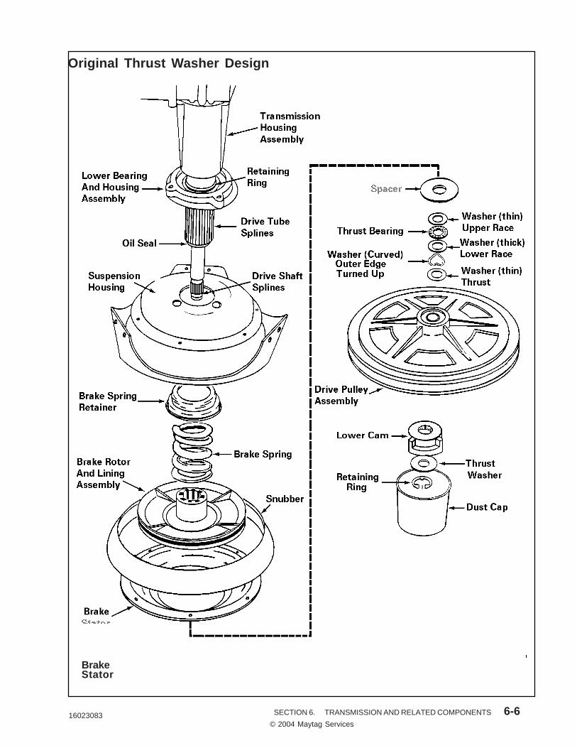
The drive pulley slips over the drive shaftand rests against a series of washers, athrust bearing, and a large washer typespacer. The spacer locates against thebottom of the brake rotor and liningassembly. (See the illustration onpage 6-6.)
The lower cam slips over the end of thedrive shaft where splines formed in thecam engage with mating splines on thedrive shaft end. This imparts a directdrive from the cam to the drive shaft.A shoulder molded on the bottom of thepulley hub engages "dogs" formed on thesides of the lower cam, and will drive itand the drive shaft in either direction.
A washer and retaining ring secure thepulley and cam on the drive shaft. Aplastic dust cap snaps to the undersideof the pulley to keep the cam surfacesclean.
OPERATION:
When the drive pulley rotates CLOCK-WISE, the upper and lower cams aredesigned to nest together which allowsthe drive pulley to remain in position onthe drive shaft. The break remains en-gaged and the drive pulley will turn thelower cam and drive the shaft to causethe transmission to agitate.
When the drive pulley rotates COUNTER-CLOCKWISE, the upper cam and pulleyride up the lower cam approximately 3/16of an inch before the driving shoulders onthe pulley hub engage the "dogs" on thelower cam.
This causes the top of the pulley hub topush against the spacer which com-presses the brake spring and lifts thebrake rotor and lining assembly off thebrake stator. The brake is disengagedand the pulley will turn the lower camand drive shaft to cause the transmissionto spin.
DRIVE PULLEY AND CAMS
The drive pulley and cam is located belowthe brake assembly on the drive shaft.
Models are equipped with a plastic drivepulley which has the upper cam molded
16023083© 2004 Maytag ServicesSECTION 6. TRANSMISSION AND RELATED COMPONENTS 6-6
Spacer
BrakeStator
Original Thrust Washer Design

16023083© 2004 Maytag ServicesSECTION 6. TRANSMISSION AND RELATED COMPONENTS 6-7
REMOVAL:
1. Disconnect the unit from the powersource.
2. Tip the unit over and remove thedrive belt.
3. Remove the dust cap from the underside of pulley.
4. Remove retaining ring and washerfrom end of drive shaft.
5. Firmly pull lower cam off the driveshaft splines, then slide the otherparts off the shaft. This will alsoallow access to the brake assemblyfor removal.
REASSEMBLY:
After reassembling the components onthe drive shaft, it will probably be neces-sary to pull down on the shaft to take theend play out of it before the thrust washerand retaining ring can be reinstalled.
NOTE: Each time the cams are reas-sembled on the drive shaft, the point inthe cam rise where the brake disengagesthe stator should be checked and ad-justed as necessary.
Reference marks have been moldedaround the bottom outer edge of thelower cam as an aid in checking the pointof brake disengagement (see followingfigure). Each mark, from right to left,represents approximately .010 of an inchcam rise.
To Check Brake Disengagement:
1. Manually rotate the drive pulley in aslow counterclockwise direction until
If the position of the pulley hub shoulderis not within these parameters and thebrake has started disengaging, adjust-ment is required.
To Adjust Brake Disengagement:
1. If the position of the pulley hubshoulder is less than 3 referencemarks, remove the standard (.062thickness) thrust washer and replaceit with a thinner (.032 thickness)thrust washer (part number 35-2132).Recheck disengagement.
2. If the position of the pulley hubshoulder is more than 9 referencemarks, add a 35-2132 thrust washer(.032) to the standard thrust washerand recheck disengagement.
the brake starts to release and thetransmission begins to turn.(See following figure).
2. Counting the reference marks on thelower cam from right to left, thepulley hub shoulder should be posi-tioned between reference marks 9and 3, with 6 being the median.(Shown in the following figure).

16023083© 2004 Maytag ServicesSECTION 6. TRANSMISSION AND RELATED COMPONENTS 6-8
BRAKE ASSEMBLY
The brake assembly is located inside thedomed area of the suspension housingand consists of the following compo-nents: brake spring retainer, brakespring, rotor and lining assembly, andthe brake stator.
The brake assembly, as well as the snub-ber, is held in position by the brake statorwhich is secured to the underside of thesuspension housing by six (6) mountingscrews.
Spring pressure forces the rotor andlining assembly down on the brake statorand prevents the transmission fromturning during agitation.
As stated previously, the drive pulley andcams provide a cam action which raisesthe drive pulley during the counterclock-wise (spin) direction of the motor. Whenthe drive pulley hub travels upward, itcompresses the brake spring and movesthe rotor and lining assembly up the drivetube disengaging it from the stator. Thetransmission is now free to spin.
Splines in the brake rotor hub mesh withsplines on the drive tube end to providepositive vertical movement for the rotorand lining assembly. The splines aregreased for ease of movement.
2. Remove the drive pulley and camcomponents as previously de-scribed.
3. Using brake removal tool number 35-2442, proceed as follows:
• Pull out and remove "U" retainerfrom tool.
• Slip the splined end of the driveshaft into hole located in the toolinner plunger.
• Looking at the side of the tool,align slots on tool barrel and holesin tool plunger between splinesand chamfered shoulder of shaft.
• Slip "U" retainer through tool slotsand holes capturing the driveshaft behind the chamfered shoul-der.
NOTE: Be sure "U" retainer iscompletely through both sides oftool.
• Tighten tool nut to compressbrake spring until transmissionturns freely.
• Remove the six (6) screws whichsecure the brake stator and snub-ber to the underside of the sus-pension housing.
• Loosen tool nut until the brakespring reaches its free length.
• Remove "U" retainer from tool andremove tool from drive shaft.
• Remove brake components.DISASSEMBLY:
1. Disconnect the unit from the powersource.
The brake assembly has a compres- sive spring force of approximately 200 pounds. See the following in- structions for disassembly.
CAUTION

16023083© 2004 Maytag ServicesSECTION 6. TRANSMISSION AND RELATED COMPONENTS 6-9
Min Pulley Hub Reference
Max Pulley Hub Reference
Reference Cam Arrow

16023083© 2004 Maytag ServicesSECTION 6. TRANSMISSION AND RELATED COMPONENTS 6-10
Transmission Housing
Crank Gear
OutputPinion
Cluster Gear
BearingHousing
DriveTube
InputShaft
LowerSeal
Agitator Shaft
Rack Gear
Transmission Cover
Rack Gear Carrier

16023083© 2004 Maytag ServicesSECTION 6. TRANSMISSION AND RELATED COMPONENTS 6-11
TRANSMISSION HOUSINGASSEMBLYThe die-cast aluminum transmissionhousing has four studs pressed into itsupper region. The studs provide mount-ing for the two crank and two clustergears. The top cover is threaded into thelower housing. A sealant is used on thethreads as a gasket material. A steeldrive tube with a splined end is pressedinto the bottom of the transmission hous-ing. A sleeve bearing is installed in thelower I. D. of the drive tube. Anotherbearing is pressed into the lower housingabove the drive tube. These bearingsprovide a path for the drive shaft to ridein. An oil seal is installed in the bottom ofthe drive tube. The oil seal can be re-placed as a separate part.
5. Remove the cone-shaped end fromthe seal protector tool and slide thetool, drive washer, and new seal overthe drive shaft up to the seal cavity.
6. Slide the transmission seal driver(tool number 14242) over the driveshaft until it makes contact with thedrive washer. Use the impact sleeveof the tool to "tap" the seal into theend of the drive tube.
Oil Seal Replacement:
The oil seal is located in the spline end ofthe drive tube. The seal can be replacedwithout removing or disassembling thetransmission, as outlined below:
1. Disconnect the unit from the powersource.
2. Remove the brake assembly toaccess the seal.
3. Use a thin, flat bladed screwdriver tocarefully pry the old seal out.
4. Place the drive washer (tool number14242) and the new seal overthe seal protector.
The lower bearing assembly consists of aball type bearing which has been installedin an aluminum die-cast housing. Thetransmission assembly must be removedfrom the washer cabinet before the lowerbearing assembly can be replaced.
The lower bearing assembly provideslateral support for the drive tube andshaft against the tension of the drive belt.The top of the suspension housingis attached to the underside of the lowerbearing assembly.
REPLACEMENT:
Because the lower bearing assembly has been pressed onto the drive tube
under approximately 1,000 pounds of pressure, a puller must be used to remove it. However, the puller forcing screw must not be used on the end of the drive shaft or the clutch assembly could be damaged. Instead, a simple pipe and cap as-
sembly can be made to slip over the drive shaft, with end clearance, and rest against the end of the drive tube.
LOWER BEARING ASSEMBLY
IMPORTANT

16023083© 2004 Maytag ServicesSECTION 6. TRANSMISSION AND RELATED COMPONENTS 6-12
5. Slip the pipe and cap assembly overthe drive shaft and up against thedrive tube.
6. Using a puller with at least a 3 1/2inch spread and sufficient reach toencompass the pipe and cap assem-bly, remove the lower bearing as-sembly.
NOTE: When installing the new lowerbearing assembly, be sure to driveagainst the inner race only to avoiddamaging the bearing shield whichcould cause premature failure.
The puller forcing screw is used on theend of the pipe cap which directs theforward thrust of the puller to the bottomof the drive tube.
REMOVAL:
1. Disconnect the unit from the powersource.
2. Remove the transmission from thewasher cabinet.
3. Remove the cams, drive pulley, andbrake assembly.
4. Remove the three (3) screws whichsecure the suspension housing tothe lower bearing assembly.

16023083© 2004 Maytag ServicesSECTION 6. TRANSMISSION AND RELATED COMPONENTS 6-13
NOTE: Before starting these tests, thewasher should be operated in the agita-tion cycle with hot water for about two(2) minutes, and then for two (2) min-utes in a spin cycle. This warms up thetransmission oil and the spin drive traincomponents.
Available Torque
Place a 1/2 inch socket and torquewrench on the agitator retaining bolt.
Depress the safety spin switch to allowthe washer to operate in the spin cycle,then while reading the torque allow thewrench to turn slowly (about 6 R.P.M.)through a complete 360 degree cycle.The reading should be between 18 and25 inch pounds throughout the complete360 degree rotation of the wrench.
Listed below are most of the servicecomplaints which would normally becaused by a malfunctioning componentof the transmission assembly.
DIAGNOSING TRANSMISSION PROBLEMS
Oil Leaks
Oil leaks can be caused by faulty seals,gaskets, or a loose fitting stud.
Slow Spin Speed
Slow spin speed can be caused by abinding tub seal and/or bearing, brakerotor assembly not disengaging properly,a slipping clutch spring, or an off balanceclothes load. The test that follows can beused to isolate the problem.
TORQUE TESTING:
A quick test of the efficiency of the spinoperation components can be made byplacing a 3 1/2 pound weight, such as abag of sand, in the washer basket andstarting the machine in the spring cycle.If the basket appears to reach full spinwith the weight, the machine compo-nents are performing as intended. If thebasket does not attain full spin speed, thetorque test procedures as outlined in thefollowing paragraphs should be per-formed to determine the problem.
The torque available to drive the spinbasket is determined by the amount ofdrag or resistance presented by the tubseal and spin bearing, deducted from theinput torque imparted to the transmissionhousing assembly by the clutch assembly.
The Following Torque Tests Will Allow aProblem in the Spin Drive Train to bePinpointed:

16023083© 2004 Maytag ServicesSECTION 6. TRANSMISSION AND RELATED COMPONENTS 6-14
If the reading is still over 4 inch pounds,the tub seal and/or spin bearing is bind-ing and should be replaced.
If the available torque reading is below18 inch pounds and the drag torquereading is not over 4 inch pounds, followthe procedure for checking the clutchassembly as to its input torque.
Input Torque
NOTE: It will be observed that thereadings used to check the input torqueare slightly lower than the readings usedto check the available torque. The rea-son for this is when the brake is disen-gaged, as in checking the availabletorque, the compressed brake springexerts a downward force on the bottomof the clutch hub and thrust washers.This keeps the clutch spring from slip-ping quite as readily as in checking theinput torque where the brake is engagedand the downward force on the clutchhub is minimized.
To check the input torque, remove thedrive pulley and position the washer sothe scale on the torque wrench can beread when it is placed on the input (drive)shaft. Attach the torque wrench adapterfirmly to the shaft, place the wrench inthe adapter and slowly rotate the wrenchin a counterclockwise direction. A prop-erly operating clutch assembly will have atorque reading between 17 and 20 inchpounds.
If the input torque is less than 17 inchpounds, the clutch assembly is defectiveand must be repaired or replaced.
If the input torque exceeds 20 inchpounds, remove the clutch assemblyfrom the transmission. Secure the drive
If the torque readings are within theselimits, the washer is performing properlyand any slow spin complaints can beassumed to have been the result of off-balance loads.
If the torque reading exceeds 25 inchpounds, the input torque outlined latershould be checked to determine thecause. Probable causes are that the driveshaft is binding in the transmission hous-ing (drive tube) sleeve bearings, or thatthe clutch spring is binding on the driveshaft hub.
If the available torque reading is less than20 pounds, follow the procedure fortesting the drag torque.
Drag Torque
Position the washer so the drive pulleycan be accessed, and remove the drivebelt. While holding the transmission tokeep it from turning, manually rotate thedrive pulley counterclockwise until thebrake stays disengaged. Make certainthe drive pulley hub shoulder has rotatedfully against the cams in the spin drivingposition to ensure the complete disen-gagement of the brake. Release thetransmission so it is free to turn.
Place a 1/2 inch socket and torquewrench on the agitator retaining bolt.
Slowly rotate the wrench 360 degrees atapproximately 6 R.P.M. and read thetorque. If the torque reading is over 4inch pounds, remove the brake stator (asdetailed earlier in this section) and re-check the drag torque.
If the torque reading is now under 4 inchpounds, the brake is binding and shouldbe repaired.

16023083© 2004 Maytag ServicesSECTION 6. TRANSMISSION AND RELATED COMPONENTS 6-15
NOTE: If the "O" ring is to be reused, beextremely careful not to damage it dur-ing the removal.
Remove the center post, "O" ring andagitator once the drive train is back inplace.
The transmission assembly, when re-moved as described, will have the relatedcomponents assembled to it. Theserelated components should be examinedcarefully before reinstalling.
When installing the transmission, it is necessary that the tub be located on the tub support a certain way if all the
mounting holes are to be properly aligned. This should be done before attempting to mount the tub to the bearing and seal housing.
To assist in correctly positioning the tub, asmall indentation has been formed on thetub support just above one of the tubbrace mounting areas. This is the leftfront tub brace.
When the tub is in proper position andready to be mounted to the tub support,the large tub cover lock (on the side ofthe tub) should be located directly abovethe indentation and tub brace.(See the illustration on page 6-14.)
pinion in a vise using two (2) small blocksof wood to prevent damage to the gearteeth, and repeat the input torque check.
If the torque reading is between 17 and20 inch pounds, the drive shaft is bindingin the sleeve bearings.
If the torque reading still exceeds 20 inchpounds, the clutch assembly is defectiveand must be repaired or replaced.
TRANSMISSION REMOVAL:
The transmission assembly can be re-moved from the washer cabinet afterremoving the drive belt, spin basket,outer tub and the suspension springs.
NOTE: Be sure to dust the base domelightly with cornstarch before installingthe transmission.
IMPORTANT
CAUTION Once the agitator has been removed, the center post slips off the shaft. Therefore, do not attempt to handle the drive train by the center post after the agitator has been removed. In- stead, after removing the agitator and the agitator shaft "O" ring, slip the center post off the shaft and handle the drive train by the shaft.

16023083© 2004 Maytag ServicesSECTION 6. TRANSMISSION AND RELATED COMPONENTS 6-16
Large TubCover Lock
AlignmentIndentation
Tub Support
Tub
Left FrontTub Brace
TUB TO TUB SUPPORT ALIGNMENT

mduckw
mduckw
16023083

mduckw
mduckw
16023083

mduckw
mduckw
16023083
mduckw
mduckw
16023083

mduckw
mduckw
16023083

mduckw
mduckw
16023083

mduckw
mduckw
16023083

mduckw
mduckw
16023083

mduckw
mduckw
16023083

mduckw
mduckw
16023083

mduckw
mduckw
16023083

mduckw
mduckw
16023083

mduckw
mduckw
16023083

mduckw
mduckw
16023083

mduckw
mduckw
16023083
mduckw
mduckw
16023083

mduckw
mduckw
16023083

16008333© 1996 Maytag Corporation
SECTION 8. CIRCUIT REVIEW 8-6
SECTION 2. WIRING INFORMATIONDLW231
SWITCH AND TIMER SEQUENCE
02468
101214
28-2628-15TM
70-72
7-327-8
9-329-8
15TM-2715TM-62
15TM-2715TM-63
26-17
70-71
TU
BT
BT
BT
BT
BT
BT
BT
BT
CAM
POS
TERM.IDENT.SWITCH FUNCTION
DEGREES20 30 40 50 60 70 80 90 100 110 120 130 140 150 160 170 180 190 200 210 220 230 240 250 260 270 280 290 300 310 320 330 340 35010
INTERVAL NUMBER
15TM-81
TO CHANGE TIMER POSITION PUSH KNOB IN AND TURN CLOCKWISE (ALL TIMER CONTACTS WILL OPEN)
ADVANCE-EX.RINSEAGITATE SELECTSPRAY RINSEWASH FILLRINSE FILLSPIN DIRECTIONAGITATE DIRECTIONAGITATE DIRECTIONSPIN DIRECTION
TM P/SW BYPASSMOTOR CONTROL NORMTM P/SW BYPASSMOTOR CONTROL-SLOWBUZZER
1 2 3 4 5 6 7 8 9 10 11 12 13 14 15 16 17 18 19 20 21 22 23 24 25 26 27 28 29 30 31 32 33 34 35 36 37 38 39 40 41 42 43 44 45 46 47 48 49 50 51 52 53 54 55 56 57 58 59 60 61 62 63 64 65 66
WASH-REGULAR
PAUSESPIN FILL AGIT
PAUSERINSE SPIN OFF EX-RINSE
SPINPAUSE SPIN OFF WASH-PERM. PRESS
PAUSE
WA
SH
OFFSPINFILLAGITRINSE
PAUSE
AGIT
PAUSE SPIN
OFF
PAUSE
FILLRINSE
TIGA
SPIN SLOWFAST FILL
PAUSE
SPRAY
SPINAGIT
mduckw
mduckw
16023083

16008333© 1996 Maytag Corporation
WIRING INFORMATIONDLW231
mduckw
mduckw
16023083
mduckw
SECTION 8. CIRCUIT REVIEW 8-7

16008333© 1996 Maytag Corporation
WIRING INFORMATIONPAV2300
SWITCH AND TIMER SEQUENCE
02468
101214
17 18 19
TU
BT
BT
BT
BT
BT
BT
BT
BT
CAM
POS
TERM.IDENT.SWITCH FUNCTION
DEGREES20 30 40 50 60 70 80 90 100 110 120 130 140 150 160 170 180 190 200 210 220 230 240 250 260 270 280 290 300 310 320 330 340 35010
INTERVAL NUMBER
AGITATE SELECTSPRAY RINSEWASH FILLRINSE FILLSPIN DIRECTIONAGITATE DIRECTIONAGITATE DIRECTIONSPIN DIRECTION
MOTOR CONTROL NORMALTM P/SW BYPASS
TM P/SW BYPASSMOTOR CONTROL-SLOW15TM-62
15TM-6315TM-27
15TM-27
9-89-32
7-87-32
70-7270-71
28-15TM28-26
1 2 3 4 5 6 7 8 9 11 12 13 14 15
WASH-REGULAR
AUSE SPIN
FILL
RINSE
P
AGIT
AUSE
P
SPIN OFF
PAUSEWASH-GENTLE SPIN
FILL AGIT
RINSE
PAUSE SPIN OFF
10 16 20 21 22 23 24 25 26 27 28 29 30 31 32 33 34 35 36 37 38 39 40 41 42 43 44 45 46 4847 605958575655545352515049PAUSENORM. SPD.
WASH-PERM. PRESS
PAUSE
SLOW SPD.
SPIN
SPRAY
WA
SH
OFFSPINFILL AGIT
RINSE
PAUSE
TO CHANGE TIMER POSITION PUSH KNOB IN AND TURN CLOCKWISE (ALL TIMER CONTACTS WILL OPEN)
mduckw
mduckw
16023083
mduckw
SECTION 8. CIRCUIT REVIEW 8-8
16008333© 1996 Maytag Corporation
WIRING INFORMATIONPAV2300
mduckw
mduckw
16023083
mduckw
SECTION 8. CIRCUIT REVIEW 8-9

16008333© 1996 Maytag Corporation
WIRING INFORMATIONPAV3200
N AND TURN CLOCKWISETO CHANGE TIMER POSITION PUSH KNOB ISWITCH AND TIMER SEQUENCE
60 6550 5540 453025
UA
60P
65
TE
ASOAK E
S
5550GI
AS4540
UAP
LIF
RP
IR
LYA
SPIN
ES
E
3530
WASHSPINSN
15 205 10OS
0 UL
CAM
L
26-12
TERM.IDENT.
70-72
U
U
L 7-32
28-26 15TM-27
15TM-62
15TM-63
1 U
P
U13LU
L98
6L
PAU
20105
SE
RINSE
15
16 12
14 U
U
L
9-8 9-32
26-16 26-17
SPIN
MINUTES
WASH
STEP INCREMENTS35
L
SHORT CYCLE
SP
IN
SOAK CYCLE
SOAK
SPRAY RINSE
SPIN DIRECTIONMOTOR CONTROL AGITATE
MOTOR CONTROL SPIN
WASH FILLRINSE FILL
SWITCH FUNCTION
LINE SWITCH/PUSH OFF
ADVANCE TO WASH
AGITATE DIRECTIONSPIN DIRECTION
MTR. CONT. SOAK SPIN
REGULAR CYCLE
AGITATE SELECT
T
TM. P. SW. BYPASS SPIN4 28-15TMU
20
AGITATE DIRECTION
L
7-8
25
70-71
8 4
SPRAY
FILL
PAUSE
AGITATE
PAUSE
AGITATE
PAU
ES
PAU
ES
PAU
ES
AGITATE
AGITATE
AGITATE
AGITATE
AGITATE
SPIN
PAUSE
ADVANCE TO WASH
mduckw
mduckw
16023083
mduckw
SECTION 8. CIRCUIT REVIEW 8-10

16008333© 1996 Maytag Corporation
WIRING INFORMATIONPAV3200
mduckw
mduckw
16023083
mduckw
SECTION 8. CIRCUIT REVIEW 8-11

16008333© 1996 Maytag Corporation
WIRING INFORMATIONPAV3300
SWITCH AND TIMER SEQUENCE
02
46
81012
14
28-2628-15TM
70-72
7-327-8
9-329-8
15TM-2715TM-63
15TM-6915TM-62
26-17
70-71
26-16TU
BT
BT
BT
BT
BT
BT
BT
BT
CAM
POS
TERM.IDENT.SWITCH FUNCTION
DEGREES20 30 40 50 60 70 80 90 100 110 120 130 140 150 160 170 180 190 200 210 220 230 240 250 260 270 280 290 300 310 320 330 340 35010
INTERVAL NUMBER
ADVANCE-WASHADVANCE-2ND RINSE
AGITATE SELECTSPRAY RINSEWASH SELECTRINSE SELECT
SPIN DIRECTIONAGITATE DIRECTION
AGITATE DIRECTIONSPIN DIRECTION
SPIN SOAKMOTOR CONTROL SPIN
TM P/SW BYPASS SMOTOR CONTROL-AGIT
BUZZER
1 2 3 4 5 6 7 8 9 10 11 12 13 14 15 16 17 18 19 20 21 22 23 24 25 26 27 28 29 30 31 32 33 34 35 36 37 41 42 43 44 45 46 4847 49 50 51 52 5453 55 56 57 58 59 60 61 62 63 64 65 66 67
15TM-81
38 39 40
OF
F
SOAK - ADVANCE TO WASHAGIT
PAUSE
FILL
SPINTIG
SPIN
PRAY
GIT
PAUSE
GIT E
SU
SPIN
PAUSE RINSEWASH-REGULAR
PAUSE SPIN
FILL AGIT
PAUSERINSE SPIN O
FF AGIT
USE
EXTRA RINSESPIN
WASH-PERM. PRESSOFF
TO CHANGE TIMER POSITION PUSH KNOB IN AND TURN CLOCKWISE (ALL TIMER CONTACTS WILL OPEN)
PA
SA A A
PA
mduckw
mduckw
16023083
mduckw
© 1996 Maytag Corporation
mduckw
SECTION 8. CIRCUIT REVIEW 8-12

16008333© 1996 Maytag Corporation
WIRING INFORMATIONPAV3300
mduckw
mduckw
16023083
mduckw
SECTION 8. CIRCUIT REVIEW 8-13

16008333© 1996 Maytag Corporation
WIRING INFORMATIONPAV5000 CONNECTION
DIAGRAMLINE VOLTAGESERVICE CORD
GND.
DOOR SW.
TAN
TAN 27
1
2 3
EMPTY FULL
8
63 WH-PUR 64
67
65
66
YELLOW
RED
P
1
MOTOR
GRN-BLK
9
YELLOWBLUE
WHITE-YELLOW
72
7O71
212O
21
HOT
COLD
16
12
WATER
SWITCH
32
7
62
8
TIMER KNOB-PUSH OFF
GRAY
LT. BLUE
ORANGE
WHITE
20
5
3
17
GND
6PM
4PM
START
15
RED-BLK
43
1617
19
YEL-BLK
32
15
28
69
26
WHITE
15
LT. BLUE
WHITE
TEMPERATURE
SPEEDSELECTORSWITCH
WATERLEVEL
SWITCH
WH-BRN
4
2 * CAPACITOR
GRN
81
TIMERMOTOR
BUZZER
ADVANCE TORINSE SWITCH
LT. BLUE
YELLOW-RED
20
18
1
6
7
10
3
8
11
4
CONTROLTEMPERATURE
WHITE-BLUE
PINK
PURPLE
WHITE-RED
WHITE-RED
WHITE-YEL.
PURPLE
PINK
RED
WATERVALVE
WHITE
GRAY
GRAY
N.O.
35-6345 "B"
SWITCH AND TIMER SEQUENCE
02468
101214
28-2628-15TM
70-72
7-327-8
9-329-8
15TM-2715TM-63
15TM-6915TM-62
26-17
70-71
26-16TU
BT
BT
BT
BT
BT
BT
BT
BT
CAM
POS
TERM.IDENT.SWITCH FUNCTION
DEGREES20 30 40 50 60 70 80 90 100 110 120 130 140 150 160 170 180 190 200 210 220 230 240 250 260 270 280 290 300 310 320 330 340 35010
INTERVAL NUMBER
ADVANCE-2ND RINSEAGITATE SELECTSPRAY RINSEWASH SELECTRINSE SELECT
SPIN DIRECTIONAGITATE DIRECTION
AGITATE DIRECTIONSPIN DIRECTION
SPIN SOAKMOTOR CONTROL SPINTM P/SW BYPASS SMOTOR CONTROL-AGIT
BUZZER
1 2 3 4 5 6 7 8 9 10 11 12 13 14 15 16 17 18 19 20 21 22 23 24 25 26 27 28 29 30 31 32 33 34 35 36 37 41 42 43 44 45 46 4847 49 50 51 52 5453 55 56 57 58 59 60 61 62 63 64 65 66 67
15TM-81
38 39 40
O F F SOAK - ADVANCE TO WASHAGIT
PAUSE
FILL
SPIN
TIG
S P IN
PRAY
GIT
PAUSE
GIT E
SU
S P IN
PAUSE RINSEWASH-REGULAR
PAUSE SPIN
FILLA G I T
PAUSERINSE SPIN OFF
AGIT
USE
EXTRA RINSE
SPIN
WASH-PERM. PRESSOFF
TO CHANGE TIMER POSITION PUSH KNOB IN AND TURN CLOCKWISE (ALL TIMER CONTACTS WILL OPEN)
PA
SA A A A
P
SPEED SELECTOR SWITCH
WASH SPEEDS
POSITION CIRCUIT
N-S
S-N
64-66 67-66
64-66 67-65
64-65 67-66
S-S 64-65 67-65
POSITION CIRCUIT
H-C
17-18-19-20
W-C 17-16-19-20, 18-43
C-C 17-16-20, 18-43
17-19-16, 18-43
ATCW-W
ATCW-C 17-20-19, 18-43
ATCC-C 17-20, 18-43
mduckw
mduckw
16023083
mduckw
SECTION 8. CIRCUIT REVIEW 8-14

16008333© 1996 Maytag Corporation
WIRING INFORMATIONPAV5000
WASH FILLHOT WATER
L1 N
LADDER WIRING DIAGRAMTIMER
12
WATERLEVEL
26 28 1 2 70 71 P P
GRAYTIMER TIMER
WATERTEMP. SW.
WH.-RED
COLD
WH.
MP
12 28 2 P P26 1 70 71
GRAYTIMER TIMER
WATERLEVEL ORANGE
PINK
HOT
WH.
MP
WASH FILLCOLD WATER
BLK
12 28 3 P P26 1 15 63 64
GRAYTIMER TIMER TIMER
WATERLEVEL LT.BLUE WH.-PUR. WH.
MP
1
SPEED SW.
BLK
66
YELLOW3
MOTOR
MOTOR AGIT.FAST
YELLOWTIMER
32
12 28 3 P P26 1 15 63 64
GRAYTIMER TIMER TIMER
WATERLEVEL LT.BLUE WH.-PUR. WH.
MPSPEED SW.
BLK
65
MOTOR AGIT.SLOW
GRN-BLK1
MOTOR
12 28 3 P P26 1 15 63 64
GRAYTIMER TIMER TIMER
WATERLEVEL LT.BLU WH.-PUR. WH.
MP
WHT-
SPEED SW.
BLK
66
MOTOR STARTAGITATE
4
START-MOTOR
YEL2
TIMER
32 9
BLU.
7 8
TIMERRED
12 P P
TIMERWH.
MPBLK
MOTOR STARTSPIN
15
SPEED SW.
62
WH-BRN YEL
67 65
START-MOTOR
4RED
2BLU.
TIMER
9 8
DOORSWITCH
BRN.
27 15
BRN.TIMER
12 26 P P
TIMERWH.
MPBLKMOTOR SPIN
FAST15 62
WH-BRN
32
DOORSWITCH
BRN.
27 15
BRN.TIMER
1
MOTOR
3YELLOW
12 26 P P
TIMERWH.
MPBLK
15 62
DOORSWITCH
BRN.
27 15
BRN.TIMER
MOTOR SPINSLOW
1
MOTOR
12 28 326 1
GRAYTIMER TIMER
WATERLEVEL
BLKT.M.
AGITATELT.-BLUE
P P
WH.
MP
WHT-
8TM
TIMER
12 26
TIMER
BLK
DOORSWITCH
BRN. BRN.T.M.SPIN
P P
WH.
MP
8TM
TIMER
HARNESS PLUGCONNECTOR END= NOT USED.
12 17
TIMER TIMER
15 P P
WH.
MP
8TM
TIMERYEL-RED
TIMER ADVANCERINSE SWITCH
FRONT TIMER PLATE
1917
T.M. ADVANCETO RINSE
27 15
TIMER
TIMERSPEED SW.
67 66
YEL.TIMER
TIMER
67 65
WH-BRN GRN-BLK
65
SPEED SW.
TIMER
LINE VOLTAGE
GRN-BLK
4
5PG23
V1
RED
GREEN-BLACKWHITEGREENBLUEYELLOWWHITE-YELLOW
LT.-BLUE
RD-BLKLT-BLU
LT-BLU
28GRAY
7RED
9BLUE
17YEL-RED
LT-BLU
WHITE62
WH-BRN63
WH-PUR
16
69YEL-BLK
27BRN
32YEL32
YEL
12BLK RD-BLK
LT-BLU 26BRN
ORANGE70
15 TM
17
LT-BLULT-BLU
WHITE-
WHITE62
WH-BRN63
WH-PUR
12BLK28
GRAY
70
7RED
9BLUE
RD-BLKLT-BLU15 TMLT-BLU
16RD-BLK
26BRN
32YEL
YEL69
YEL-BLK27
BRN
32
26
YEL-RED
BLK
V
REDRUN
START
4P MAINYEL
132
GP5
4
SCHEMATIC
PUR
WHT
EMERSON
6P MAIN
ORANGE PROT
AUX
BLUE
5
32
TIMER
7
* CAPACITOR USED WITH ALTERNATE CAPACITOR START MOTOR.
15
TIMER
15
TIMER
SPEED SW.
BLK
12 26
TIMERBRN.
DOORSWITCH
BRN.
27 15
TIMER
15 81
TIMER
12
TIMER
P P
WH.
8BUZ
TIMERMP
BUZZER
81TAN
81TAN
TAN
WHITE WHITE
YELLOWYELLOWWHITE-
TIMERW.S.22 21
WHITE WHT-YEL
8
TIMERW.S.20 21
WHITE WHT-YEL
8
YEL
WHT-YEL
WHT-YEL
WHT-YEL
YEL
WHT-YEL
72WH-BLU
71WH-RED
71WH-RED ORANGE
72WH-BLU
BL
TEMP. CONT. BOARD
ORANGE PINK
410
WH.-RED
17 20
WATERTEMP. SW.
WH.-YEL.TEMP. CONT. BOARD
9 3
PURPLETIMER
5 11
GR
AY
10
PIN
K
9
WH
ITE
/YE
LLO
W, D
/STR
IPE
8
GR
AY
7
RE
D
6
WH
ITE
/RE
D,
D/S
TR
IPE
4
PIN
K
3
VIO
LET
2
CLO
SE
D U
P
TEMPERATURE CONTROLBOARD
4
WH
ITE
mduckw
mduckw
16023083
mduckw
SECTION 8. CIRCUIT REVIEW 8-15

16008333© 1996 Maytag Corporation
WIRING INFORMATIONPAV5157, PAV5158
SWITCH AND TIMER SEQUENCE
0
2
4
6
8
10
12
14
28-2628-15TM
70-72
7-327-8
9-329-8
15TM-2715TM-63
15TM-6915TM-62
26-17
70-71
26-16TU
BT
BT
BT
BT
BT
BT
BT
BT
CAM
POS
TERM.IDENT.SWITCH FUNCTION
DEGREES20 30 40 50 60 70 80 90 100 110 120 130 140 150 160 170 180 190 200 210 220 230 240 250 260 270 280 290 300 310 320 330 340 35010
* INTERVAL NUMBER
ADVANCE-WASHADVANCE-2ND RINSEAGITATE SELECTSPRAY RINSEWASH SELECTRINSE SELECTSPIN DIRECTIONAGITATE DIRECTIONAGITATE DIRECTIONSPIN DIRECTIONSPIN SOAKMOTOR CONTROL SPINTM P/SW BYPASS SMOTOR CONTROL-AGIT
BUZZER
1 2 3 4 5 6 7 8 9 10 11 12 13 14 15 16 17 18 19 20 21 22 23 24 25 26 27 28 29 30 31 32 33 34 35 36 37 41 42 43 44 45 46 4847 49 50 51 52 5453 55 56 57 58 59 60 61 62 63 64 65 66 67
15TM-81
38 39 40
OF
F
SOAK - ADVANCE TO WASHAGIT
PAUSE
FILL
SPINTIG
SPIN
PRAY
GIT
PAUSE
GIT E
SU
SPIN
PAUSE RINSEWASH-REGULAR
PAUSE SPIN
FILL AGIT
PAUSERINSE SPIN OFF
AGIT
USE
EXTRA RINSESPIN
WASH-PERM. PRESSOFF
TO CHANGE TIMER POSITION PUSH KNOB IN AND TURN CLOCKWISE (ALL TIMER CONTACTS WILL OPEN)
PA
SA A A A
P
*120 SECONDS PER INTERVAL
mduckw
mduckw
16023083
mduckw
SECTION 8. CIRCUIT REVIEW 8-16

16008333© 1996 Maytag Corporation
WIRING INFORMATIONPAV5157, PAV5158
mduckw
mduckw
16023083
mduckw
SECTION 8. CIRCUIT REVIEW 8-17

16008333© 1996 Maytag Corporation
WIRING INFORMATIONPAVT344
mduckw
mduckw
16023083
mduckw
SECTION 8. CIRCUIT REVIEW 8-18

16008333© 1996 Maytag Corporation
WIRING INFORMATIONPAVT344
mduckw
mduckw
16023083
mduckw
SECTION 8. CIRCUIT REVIEW 8-19

16008333© 1996 Maytag Corporation
WIRING INFORMATIONHAV2460
mduckw
mduckw
16023083
mduckw
SECTION 8. CIRCUIT REVIEW 8-20

16008333© 1996 Maytag Corporation
WIRING INFORMATIONHAV2460
mduckw
mduckw
16023083
mduckw
SECTION 8. CIRCUIT REVIEW 8-21

16008333© 1996 Maytag Corporation
WIRING INFORMATIONPAVT244
mduckw
mduckw
16023083
mduckw
SECTION 8. CIRCUIT REVIEW 8-22

16008333© 1996 Maytag Corporation
WIRING INFORMATIONPAVT244
mduckw
mduckw
16023083
mduckw
SECTION 8. CIRCUIT REVIEW 8-23

16008333© 1996 Maytag Corporation
WIRING INFORMATIONPAVT234, HAV2360, MAV2200
mduckw
mduckw
16023083
mduckw
SECTION 8. CIRCUIT REVIEW 8-24

16008333© 1996 Maytag Corporation
WIRING INFORMATIONPAVT234, HAV2360, MAV2200
mduckw
mduckw
16023083
mduckw
SECTION 8. CIRCUIT REVIEW 8-25

16008333© 1996 Maytag Corporation
WIRING INFORMATIONHAV2557/2558
mduckw
mduckw
16023083
mduckw
SECTION 8. CIRCUIT REVIEW 8-26

16008333© 1996 Maytag Corporation
WIRING INFORMATIONHAV2557/2558
mduckw
mduckw
16023083
mduckw
SECTION 8. CIRCUIT REVIEW 8-27

16008333© 1996 Maytag Corporation
WIRING INFORMATIONHAV3460
mduckw
mduckw
16023083
mduckw
SECTION 8. CIRCUIT REVIEW 8-28

16008333© 1996 Maytag Corporation
WIRING INFORMATIONHAV3460
mduckw
mduckw
SECTION 8. CIRCUIT REVIEW 8-29

16008333© 1996 Maytag Corporation
WIRING INFORMATIONPAVT444, HAV4657
mduckw
mduckw
16023083
mduckw
SECTION 8. CIRCUIT REVIEW 8-30

16008333© 1996 Maytag Corporation
WIRING INFORMATIONPAVT444, HAV4657
mduckw
mduckw
16023083
mduckw
SECTION 8. CIRCUIT REVIEW 8-31

mduckw
mduckw
16023083
mduckw
mduckw
SECTION 8. CIRCUIT REVIEW 8-32

mduckw
mduckw
16023083

mduckw
mduckw
16023083

mduckw
mduckw
16023083

mduckw
mduckw
16023083

mduckw
mduckw
16023083

mduckw
mduckw
16023083

mduckw
mduckw
16023083
mduckw
mduckw
mduckw
SECTION 9. TROUBLESHOOTING 9-8

mduckw
mduckw
16023083
mduckw
mduckw
SECTION 9. TROUBLESHOOTING 9-9

16008333© 1996 Maytag Corporation
TEMPERATURE CONTROL BOARDModel: PAV5000
The temperature control board receives information fromthe water temperature switch about the user’s waterselections. The thermistor located in the water valve,provides inputs to the board, as it detects the incomingwater temperature. This information combined with theselections on the temperature control switch determinethe output signals to the water valve. The target coldtemperature is 75° F, ± 5° F. The target warm temperatureis 95° F, ± 5° F. The temperature control system isintended to warm wash fills when necessary to the targettemperature. It will not cool a fill when the inlet temeratureexceeds the minimum target temperature.The analog board monitors the water temperature and willturn the valves ON and OFF to maintain proper watertemperature. When the water temperature is set onWARM, both valves are on. The longer the valve is ON,the lower the water temperature will drop in the waterlines. As the temperature drops the automatic tempera-ture control will cycle the water valve to maintain theproper water temperature. Rinse fills are not temperaturecontrolled unless warm rinse is selected.
Analog Automatic Temperature Control (ATC) Table
The analog automatic temperature control (ATC) tabledepicts the philosophy of how the automatic temperaturecontrol board operates. The thermistor temp representsthe temperature sensed by the thermistor in the watervalve. The outputs are indicative of the board sendingvoltage to the water valve solenoids.
Note: With the temperature control selector in theON position.The only combinations wherethe temperature control board is active(BOLD) are warm and cold.
When cold is selected and the temperature sensed bythe thermistor is too low at the valve, the hot valve will beactivated.
When warm is selected and the temperature sensed bythe thermistor is too cool, the cold valve will be shut off.
Water Temp Selections
ATC Selector Thermistor Temp
Hot Valve Output
Cold Valve Output
Hot Off Low On Off Warm Off Low On On Cold Off Low Off On Hot Off High On Off
Warm Off High On On Cold Off High Off On Hot On Low On Off
Warm On Low On Off Cold On Low On On Hot On High On Off
Warm On High On On Cold On High Off On
mduckw
mduckw
16023083
mduckw
SECTION 9. TROUBLESHOOTING 9-10

16008333© 1996 Maytag Corporation
Analog Temperature Board TestsTo test the temperature board for proper function, use thediagnostics chart below in conjunction with the 11 termi-nal pin connector and an ohm meter.
TEMPERATURE CONTROL BOARD
5 11
GR
AY
10
PIN
K
9
WH
ITE/
YELL
OW
, D/S
TRIP
E
8
GR
AY
7
RE
D
6
WH
ITE
/RE
D, D
/STR
IPE
4
PIN
K
3
VIO
LET
2
CLO
SED
UP
TEMPERATURE CONTROLBOARD
4
WH
ITE
Analog Temperature Control Board DiagnosticsChart
PIN SOURCE OUTPUT/INPUT WIRE COLOR MEASURE TO PIN #
VOLTS OHMS
CONDITIONS
1 Neutral Input WHITE Line 120VAC 2 Not Used
3 Cold Valve Output VIOLET 1 120VAC
4 Hot Valve Output PINK 1 120VAC
6 Timer (12 T Contact) Input WHITE/RED,
D/STRIPE 1 120VAC Wash Cycle on Timer
7 TC Disable Input RED 6
OVDC 3-
24VDC
TC Option Deselected TC Option Selected
8 Thermistor Input GRAY 11 10K-100K
OHMS Room Temperature
9
Temp Selector Switch Cold Wash
Input WHITE/YELLOW, D/STRIPE 6 * ** OVDC Warm or Cold Wash
Selected
10
Temp Selector
Switch Hot Wash
Input PINK 6 * ** OVDC Hot or Warm Wash Selected
11 Thermistor Input GRAY 8 10K-100K
OHMS Room Temperature
* Reference DC voltages to line 1.** Temperature only occurs during cold or warm wash fills.
mduckw
mduckw
16023083
mduckw
SECTION 9. TROUBLESHOOTING 9-11

mduckw
16023083