16-BIT MICROCONTROLLER EMBEDDED C PROGRAMMING MANUAL … … · fujitsu semiconductor controller...
243
FUJITSU SEMICONDUCTOR CONTROLLER MANUAL F 2 MC-16 FAMILY 16-BIT MICROCONTROLLER EMBEDDED C PROGRAMMING MANUAL FOR fcc907 CM42-00327-1E
-
Upload
vuonghuong -
Category
Documents
-
view
278 -
download
4
Transcript of 16-BIT MICROCONTROLLER EMBEDDED C PROGRAMMING MANUAL … … · fujitsu semiconductor controller...
FUJITSU SEMICONDUCTORCONTROLLER MANUAL
F2MC-16 FAMILY16-BIT MICROCONTROLLER
EMBEDDED CPROGRAMMING MANUAL
FOR fcc907
CM42-00327-1E

F2MC-16 FAMILY16-BIT MICROCONTROLLER
EMBEDDED CPROGRAMMING MANUAL
FOR fcc907
FUJITSU LIMITED

PREFACE
■ Objectives and Intended Reader
The F2MC-16L/16LX/16/16H/16F (hereafter collectively referred to as the F2MC-16 Family) are16-bit microcontrollers designed for embedded systems.
This manual provides information required for using the fcc907 F2MC-16 family C compiler tocreate an embedded system. The manual explains how to create C programs that effectively
use the F2MC-16 family architecture and provides notes related to the creation of C programs.
This manual is intended for engineers who use the fcc907 to develop application programs for
the F2MC-16 family. Be sure to read this manual completely.
■ Trademarks
Softune is a registered trademark of Fujitsu Limited.
Other system names and product names in this manual are trademarks of their respectivecompanies or organizations. The symbols ™ and ® are sometimes omitted in the text.
■ Structure of This Manual
This manual consists of the three parts listed below.
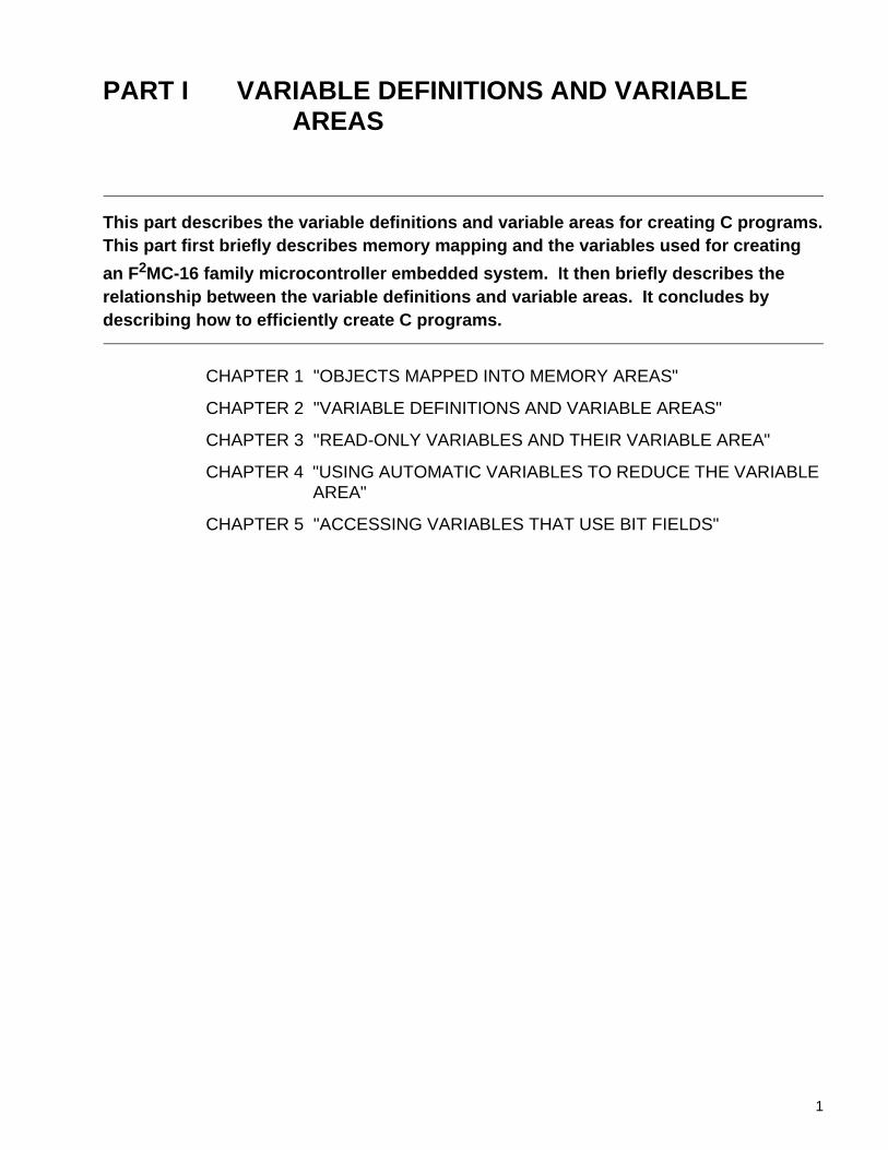
PART I "VARIABLE DEFINITIONS AND VARIABLE AREAS"
Part I describes the variable definitions and variable areas for creating C programs.
CHAPTER 1 "OBJECTS MAPPED INTO MEMORY AREAS"
This chapter briefly describes the memory mapping for a systems in which an F2MC-16family microcontroller was embedded.
CHAPTER 2 "VARIABLE DEFINITIONS AND VARIABLE AREAS"
This chapter describes the variable definitions and variable areas to which the results ofcompilation are output. It also describes the variable areas for variables that are initialized atdefinition and the variable area for those that are not. In addition, the chapter describesvariables declared as "static."
CHAPTER 3 "READ-ONLY VARIABLES AND THEIR VARIABLE AREA"
This chapter describes how to use variables declared with the type-qualifier "const" that areonly read at execution time and provides notes on their use. This chapter also discusses thereduction of the variable area and object efficiency for referencing when the "const" typemodifier is used.
CHAPTER 4 "USING AUTOMATIC VARIABLES TO REDUCE THE VARIABLE AREA"
This chapter explains how to reduce the variable area by using automatic variables. Area isallocated to automatic variables at execution time.
CHAPTER 5 "ACCESSING VARIABLES THAT USE BIT FIELDS"
This chapter describes how to access variables that use bit fields.
i
PART II "USING STACK AREA EFFICIENTLY"
Part II describes how to use the stack area efficiently.
CHAPTER 6 "FUNCTION CALLS AND THE STACK"
This chapter briefly describes the stack area used when a function is called.
CHAPTER 7 "REDUCING FUNCTION CALLS BY EXPANDING FUNCTIONS IN LINE"
This chapter describes how to reduce the stack area by using inline expansion of functions infunction calls.
CHAPTER 8 "REDUCING THE ARGUMENTS TO CONSERVE STACK AREA"
This chapter describes how to reduce the number of arguments in function calls so that lessstack area is required.
CHAPTER 9 "CONSERVING STACK AREA BY IMPROVEMENTS ON THE AREA FORFUNCTION RETURN VALUES"
This chapter explains the function return values for the register and the stack. Reducing thereturn values for the stack can reduce the used stack area.
PART III "USING LANGUAGE EXTENSIONS"
Part III describes the language extensions specific to the fcc907. Part III also discussesitems in the extended language specifications that require special attention.
CHAPTER 10 "WHAT ARE LANGUAGE EXTENSIONS?"
This chapter describes the fcc907-specific extended language specifications, such as thequalifier for extensions, _ _asm statement, and "#pragma."
CHAPTER 11 "NOTES ON ASSEMBLER PROGRAMS IN C PROGRAMS"
This chapter provides notes on including assembler code with the _ _asm statements and#pragma asm/endasm of the extended language specifications.
CHAPTER 12 "NOTES ON DEFINING AND ACCESSING THE I/O AREA"
This chapter provides notes on specifying and mapping when using the _ _io type qualifier.
CHAPTER 13 "MAPPING VARIABLES QUALIFIED WITH THE _ _direct TYPE QUALIFIER"
This chapter provides notes on specifying and allocating variables declared with the _ _directtype qualifier.
CHAPTER 14 "CREATING AND REGISTERING INTERRUPT FUNCTIONS"
This chapter provides notes on using language extensions of the fcc907 to enable interruptprocessing.
PART IV "MAPPING OBJECTS EFFECTIVELY"
This part explains how to map objects effectively.
CHAPTER 15 "MEMORY MODELS AND OBJECT EFFICIENCY"
This chapter describes the memory models of the fcc907 and explains object efficiency.
CHAPTER 16 "MAPPING VARIABLES QUALIFIED WITH THE TYPE QUALIFIER CONST"
This chapter provides notes on mapping variables declared with the type qualifier const.
CHAPTER 17 "MAPPING PROGRAMS IN WHICH THE CODE AREA EXCEEDS 64 Kbytes"
This chapter describes how to map programs when the code area exceeds 64 Kbytes.
CHAPTER 18 "MAPPING PROGRAMS IN WHICH THE DATA AREA EXCEEDS 64 Kbytes"
This chapter describes how to map programs when the data area exceeds 64 Kbytes.
ii
In this manual, the designation <Notes> indicates items requiring special attention.
The sections entitled "Tip" provide information on functions that is useful for creating programs.
The Softune C Checker analyzes C source programs and outputs a warning for items requiringattention to ensure that the fcc907 does not output an error message.
The Softune C Analyzer analyzes function calls within the C source code of the program anddisplays information about such items as variables, relationship between function references,and the used amount of stack areas.
iii
© 2000 FUJITSU LIMITED Printed in Japan
1. The contents of this document are subject to change without notice. Customers are advised to consultwith FUJITSU sales representatives before ordering.
2. The information and circuit diagrams in this document are presented as examples of semiconductordevice applications, and are not intended to be incorporated in devices for actual use. Also, FUJITSU isunable to assume responsibility for infringement of any patent rights or other rights of third partiesarising from the use of this information or circuit diagrams.
3. The contents of this document may not be reproduced or copied without the permission of FUJITSULIMITED.
4. FUJITSU semiconductor devices are intended for use in standard applications (computers, officeautomation and other office equipments, industrial, communications, and measurement equipments,personal or household devices, etc.).CAUTION:Customers considering the use of our products in special applications where failure or abnormaloperation may directly affect human lives or cause physical injury or property damage, or whereextremely high levels of reliability are demanded (such as aerospace systems, atomic energy controls,sea floor repeaters, vehicle operating controls, medical devices for life support, etc.) are requested toconsult with FUJITSU sales representatives before such use. The company will not be responsible fordamages arising from such use without prior approval.
5. Any semiconductor devices have inherently a certain rate of failure. You must protect against injury,damage or loss from such failures by incorporating safety design measures into your facility andequipment such as redundancy, fire protection, and prevention of over-current levels and otherabnormal operating conditions.
6. If any products described in this document represent goods or technologies subject to certainrestrictions on export under the Foreign Exchange and Foreign Trade Control Law of Japan, the priorauthorization by Japanese government should be required for export of those products from Japan.
iv
CONTENTS
PART I VARIABLE DEFINITIONS AND VARIABLE AREAS ........................................... 1
CHAPTER 1 OBJECTS MAPPED INTO MEMORY AREAS ............................................. 31.1 Program Components ............................................................................................................................ 41.2 Mapping into Memory Areas .................................................................................................................. 61.3 Dynamically Allocated Variables ............................................................................................................ 81.4 Statically Allocated Variables ............................................................................................................... 10
CHAPTER 2 VARIABLE DEFINITIONS AND VARIABLE AREAS ................................ 132.1 External Variables and Their Variable Area ......................................................................................... 142.2 Initial Values and Variable Area for External Variables ....................................................................... 172.3 Initialized Variables and Initialization at Execution .............................................................................. 192.4 Variables Declared as "static" and Their Variable Area ....................................................................... 21
2.4.1 Example of Function with Static Global Variable ............................................................................ 232.4.2 Example of aunction with Static Local Variable .............................................................................. 24
CHAPTER 3 READ-ONLY VARIABLES AND THEIR VARIABLE AREA ...................... 253.1 Numeric Constants and #define Definition .......................................................................................... 263.2 Defining Variables Using the const Type Qualifier .............................................................................. 28
CHAPTER 4 USING AUTOMATIC VARIABLES TO REDUCE THE VARIABLE AREA ........................................................................................ 31
4.1 Automatic Variables and Statically Allocated Variables ....................................................................... 324.2 Using Automatic Variables ................................................................................................................... 35
CHAPTER 5 ACCESSING VARIABLES THAT USE BIT FIELDS .................................. 395.1 Boundary Alignment of fcc907 ............................................................................................................. 405.2 Bit Field Definitions and Boundary Alignment ...................................................................................... 415.3 Accessing I/O Areas Using Bit Fields and Unions ............................................................................... 44
PART II USING STACK AREA EFFICIENTLY ................................................................. 45
CHAPTER 6 FUNCTION CALLS AND THE STACK ....................................................... 476.1 Areas Allocated on the Stack during Function Calls ............................................................................ 486.2 Stack States When Function Calls Are Nested ................................................................................... 50
CHAPTER 7 REDUCING FUNCTION CALLS BY EXPANDING FUNCTIONS IN LINE......................................................................................................... 51
7.1 Inline Expansion of Function ................................................................................................................ 527.2 Conditions for Inline Expansion of Function ........................................................................................ 55
v
CHAPTER 8 REDUCING ARGUMENTS TO CONSERVE STACK AREA ..................... 578.1 Passing Arguments During Function Calls ......................................................................................... 58
8.1.1 Normal Argument Passing ............................................................................................................. 598.1.2 Argument Structure Passing .......................................................................................................... 608.1.3 Structure Address Passing ............................................................................................................ 618.1.4 Stack Status During Function Calls ............................................................................................... 62
8.2 Conditions for Structure Address Transfer .......................................................................................... 63
CHAPTER 9 CONSERVING STACK AREA BY IMPROVEMENTS ON THE AREA FOR FUNCTION RETURN VALUES ................................................................... 65
9.1 Return Value of Functions .................................................................................................................. 669.2 Functions Returning Structure-type Values and Stack Conservation ................................................. 739.3 Functions Returning Union-type Values and Stack Conservation ...................................................... 77
PART III USING LANGUAGE EXTENSIONS .................................................................... 81
CHAPTER 10 WHAT ARE LANGUAGE EXTENSIONS? ................................................. 8310.1 Coding Assembler Instructions Using an _ _asm Statement .............................................................. 8410.2 Extended Type Qualifiers .................................................................................................................... 85
10.2.1 _ _near Type Qualifier and _ _far Type Qualifier ........................................................................... 8610.2.2 _ _io Type Qualifier ........................................................................................................................ 8810.2.3 _ _direct Type Qualifier .................................................................................................................. 9010.2.4 _ _interrupt Type Qualifier ............................................................................................................. 9110.2.5 _ _nosavereg Type Qualifier .......................................................................................................... 93
10.3 Extended Functions Using #pragma ................................................................................................... 9510.3.1 Inserting Assembler Programs Using #pragma asm/endasm ........................................................ 9610.3.2 Specifying Inline Expansion Using #pragma inline ........................................................................ 9710.3.3 Using #pragma section to Change Section Names and Specify Mapping Address ...................... 9910.3.4 Specifying the Interrupt Level Using #pragma ilm/noilm .............................................................. 10110.3.5 Setting the Register Bank Using #pragma register/noregister ..................................................... 10310.3.6 Setting Use of the System Bank Using #pragma ssb/nossb ........................................................ 10510.3.7 Setting the Stack Bank Automatic Identification Function Using #pragma except/noexcept ....... 10710.3.8 Generating an Interrupt Vector Table Using #pragma intvect/defvect ......................................... 109
10.4 Interrupt-Related Built-in Functions ................................................................................................. 11110.4.1 Disabling Interrupts Using _ _DI( ) ............................................................................................... 11210.4.2 Enabling Interrupts Using _ _EI( ) ................................................................................................ 11310.4.3 Setting the Interrupt Level Using _ _set_il( ) ................................................................................ 114
10.5 Other Built-in Functions .................................................................................................................... 11510.5.1 Outputting a Nop Instruction Using _ _wait_nop( ) ...................................................................... 11610.5.2 Signed 16-Bit Multiplication Using _ _mul( ) ................................................................................ 11710.5.3 Unsigned 16-Bit Multiplication Using _ _mulu( ) .......................................................................... 11810.5.4 Signed 32-Bit/Signed 16-Bit Division Using _ _div( ) ................................................................... 11910.5.5 Unsigned 32-Bit/Unsigned 16-Bit Division Using _ _divu( ) ......................................................... 12010.5.6 Signed 32-Bit/Signed 16-Bit Remainder Calculation Using _ _mod( ) ......................................... 12110.5.7 Unsigned 32-Bit/Unsigned 16-Bit Remainder Calculation Using _ _modu( ) ............................... 122
vi
CHAPTER 11 NOTES ON ASSEMBLER PROGRAM IN C PROGRAMS ...................... 12311.1 Including Assembler Code in C Programs ......................................................................................... 12411.2 Differences Between Using the _ _asm Statement and #pragma asm/endasm ............................... 127
CHAPTER 12 NOTES ON DEFINING AND ACCESSING THE I/O AREA ..................... 13112.1 M90678 Series I/O Areas .................................................................................................................. 13212.2 Defining and Accessing Variables Mapped into the I/O Area ............................................................ 134
CHAPTER 13 MAPPING VARIABLES QUALIFIED WITH THE _ _direct TYPE QUALIFIER ...................................................................... 141
13.1 Output Sections of and Access to Variables Qualified by the _ _direct Type Qualifier ..................... 14213.2 Mapping Variables Qualified by the _ _direct Type Qualifier ............................................................. 144
CHAPTER 14 CREATING AND REGISTERING INTERRUPT FUNCTIONS .................. 14714.1 F2MC-16 Family Interrupts ................................................................................................................ 14814.2 Required Hardware Settings for Interrupts ........................................................................................ 150
14.2.1 Setting the System Stack Area ..................................................................................................... 15114.2.2 Initializing Resources .................................................................................................................... 15314.2.3 Setting Interrupt Control Registers ............................................................................................... 15414.2.4 Starting Resource Operation ........................................................................................................ 15614.2.5 Enabling CPU Interrupts ............................................................................................................... 157
14.3 Using the _ _interrupt Type Qualifier to Define Interrupt Functions ................................................... 16214.4 Setting of Interrupt Vectors ................................................................................................................ 166
PART IV MAPPING OBJECTS EFFECTIVELY ............................................................... 169
CHAPTER 15 MEMORY MODELS AND OBJECT EFFICIENCY ................................... 17115.1 Four Memory Models ......................................................................................................................... 17215.2 Large Models and Object Efficiency .................................................................................................. 175
CHAPTER 16 MAPPING VARIABLES QUALIFIED WITH THE TYPE QUALIFIER CONST ........................................................................ 177
16.1 Using the Mirror ROM Function and const Type Qualifier ................................................................. 17816.1.1 const Type Qualifier and Mirror ROM Function for Small and Medium Models .......................... 17916.1.2 const Type Qualifier and Mirror ROM Function for Compact and Large Models .......................... 182
16.2 const Type Qualifier When the Mirror ROM Function Cannot Be Used ............................................ 18416.2.1 Mapping Variables Qualified by the const Type Qualifier to RAM Area ....................................... 18516.2.2 Specifying the const Type and _ _far Type Qualifiers at Definition .............................................. 187
CHAPTER 17 MAPPING PROGRAMS IN WHICH THE CODE AREA EXCEEDS 64 Kbytes................................................................................................... 189
17.1 Functions Calls of Programs in Which the Code Area Exceeds 64 Kbytes ....................................... 19017.2 Using Calls For Functions Qualified by the _ _far Type Qualifier ...................................................... 19117.3 Mapping Functions Qualified by the _ _far Type Qualifier ................................................................. 194
17.3.1 Functions Qualified by the _ _far Type Qualifier for Small and Compact Models ........................ 19517.3.2 Functions Qualified by the _ _far Type Qualifier for Medium and Large Models .......................... 197
17.4 Using Calls for Functions Qualified by the _ _near Type Qualifier .................................................... 200
vii
17.5 Mapping Functions Qualified by the _ _near Type Qualifier ............................................................. 202
CHAPTER 18 MAPPING PROGRAMS IN WHICH THE DATA AREA EXCEEDS 64 Kbytes .................................................................................................. 205
18.1 Function Calls of Programs Where the Data Area Exceeds 64 Kbytes ............................................ 20618.2 Using Calls For Variables Qualified by the _ _far Type Qualifier ...................................................... 20818.3 Mapping Variables Qualified by the _ _far Type Qualifier ................................................................. 210
18.3.1 Variables Qualified by the _ _far Type Qualifier for Small and Medium Models .......................... 21118.3.2 Variables Qualified by the _ _far Type Qualifier for Compact and Large Models ........................ 214
18.4 Using Calls For Variables Qualified by the _ _near Type Qualifier ................................................... 21718.5 Mapping Variables Qualified by the _ _near Type Qualifier .............................................................. 219
INDEX...................................................................................................................................223
viii
PART I VARIABLE DEFINITIONS AND VARIABLE AREAS
This part describes the variable definitions and variable areas for creating C programs.This part first briefly describes memory mapping and the variables used for creating
an F2MC-16 family microcontroller embedded system. It then briefly describes the relationship between the variable definitions and variable areas. It concludes by describing how to efficiently create C programs.
CHAPTER 1 "OBJECTS MAPPED INTO MEMORY AREAS"
CHAPTER 2 "VARIABLE DEFINITIONS AND VARIABLE AREAS"
CHAPTER 3 "READ-ONLY VARIABLES AND THEIR VARIABLE AREA"
CHAPTER 4 "USING AUTOMATIC VARIABLES TO REDUCE THE VARIABLE AREA"
CHAPTER 5 "ACCESSING VARIABLES THAT USE BIT FIELDS"
1

2
CHAPTER 1 OBJECTS MAPPED INTO MEMORY AREAS
This chapter briefly describes objects that are mapped into memory areas before taking up the subject of the variable.
1.1 "Program Components"
1.2 "Mapping into Memory Areas"
1.3 "Dynamically Allocated Variables"
1.4 "Statically Allocated Variables"
3
CHAPTER 1 OBJECTS MAPPED INTO MEMORY AREAS
1.1 Program Components
This section briefly describes the program components.Programs can be roughly divided into code and data.
■ Program Components
Programs created in C (C programs hereafter) and programs created in Assembler (assemblerprograms hereafter) can both be roughly divided into code and data sections.
❍ Code
This section in the program contains the machine instructions to be executed by the CPU.
The algorithm, which is coded as functions in a C program, is compiled and converted tomachine instruction code.
The term "Code" refers to a set of execution instructions that are only read at execution.
❍ Data
The data is accessed by the program.
In a C program, the data includes variables, character strings, literal constants, and initialvalues.
Data can be read and written depending on the processing.
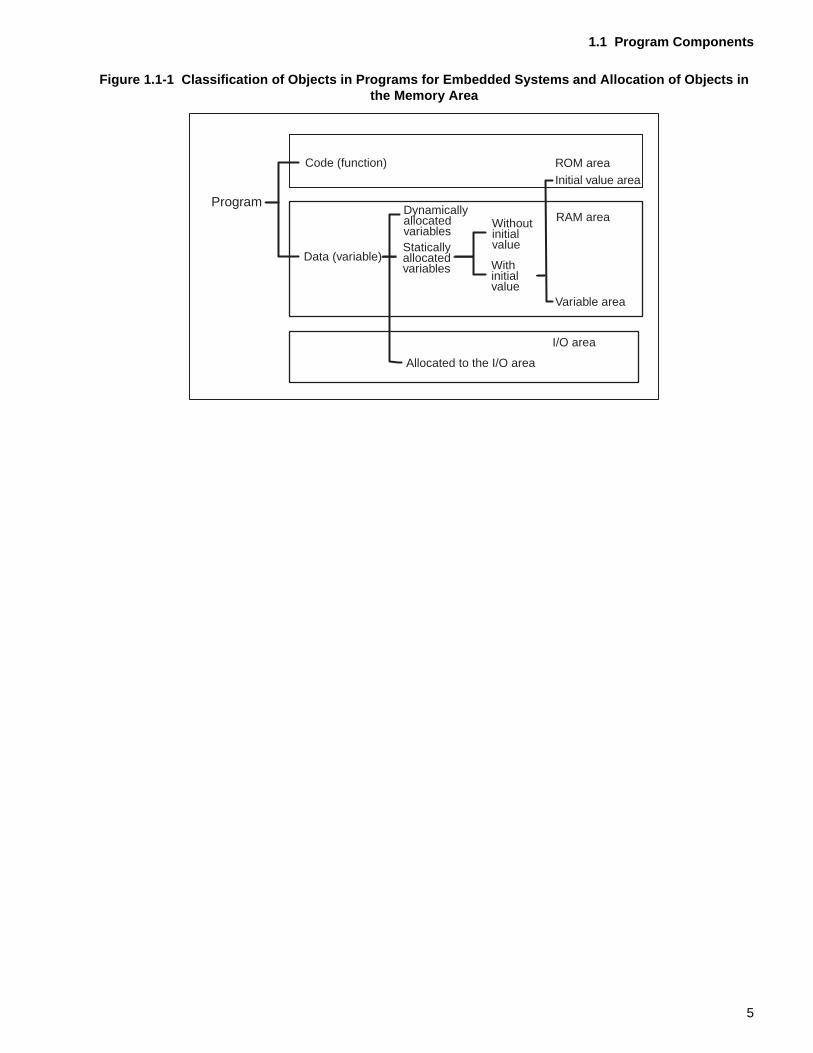
A C program can be classified as shown in Figure 1.1-1 "Classification of Objects in Programsfor Embedded Systems and Allocation of Objects in the Memory Area". Variables, which aredata items, can be classified into three types: Variables that are allocated dynamically,variables that are allocated statically, and variables that are allocated to the I/O area.
Dynamically allocated variables are allocated in a stack. Statically allocated variables can beclassified into variables that are initialized and variables that are not. Initialized variables can beallocated both in the initial value area and the variable area.
ProgramCode (machine instruction): Read only
Data: Read and write
4
1.1 Program Components
Figure 1.1-1 Classification of Objects in Programs for Embedded Systems and Allocation of Objects in the Memory Area
Program
Code (function)
Data (variable)
DynamicallyallocatedvariablesStaticallyallocatedvariables
Allocated to the I/O area
Withoutinitialvalue
Withinitialvalue
ROM areaInitial value area
RAM area
Variable area
I/O area
5
CHAPTER 1 OBJECTS MAPPED INTO MEMORY AREAS
An
p rou-
1.2 Mapping into Memory Areas
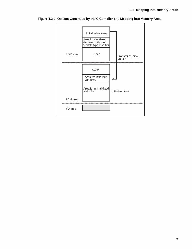
This section briefly describes the types of memory areas and the objects that are mapped into them.
In embedded systems that use an F 2MC-16 family microcontroller, the memory area can be mainly classified into ROM, RAM, and I/O area.
■ Mapping into Memory Areas
An embedded system that uses an F2MC-16 family microcontroller uses three types of memoryareas: ROM area, RAM area, and I/O area.
❍ Read only memory (ROM) area
Objects mapped into the ROM area can only be read.
The code and initial value areas are allocated in the ROM area.
❍ Random access memory (RAM) area
Objects mapped into the RAM area can be read and written.
The data areas that are read and written to during program execution are allocated in the RAMarea.
Stacks are also allocated in the RAM area.
❍ Input/output (I/O) area
I/O objects are mapped into the I/O area.
As shown in Figure 1.2-1 "Objects Generated by the C Compiler and Mapping into MemoryAreas", code and the initial values of variables that can only be read at execution time aremapped into the ROM area. Variables that are read and written at execution time are mappedinto the RAM area.
<Notes>
Since the values in the RAM area are undefined at system start, variables that are mappedinto the RAM area must be initialized as described below before program execution:
• Variable areas that are not initialized must be initialized to 0.
• The variables in the RAM area must be initialized using the initial values in the ROM area.
This initialization operation are performed using an initialization program called a startup
routine1.
The objects are mapped into their memory area during linking.
1. The startup routine is a program that performs initialization before executing the C program.example for this is the program startup.asm supplied as a sample with the C compiler. Refer to the C compiler manual for information about the operations performed by the startutine.
6
1.2 Mapping into Memory Areas
Figure 1.2-1 Objects Generated by the C Compiler and Mapping into Memory Areas
Initial value area
Area for variablesdeclared with the"const" type modifier
Code
Stack
Area for initializedvariables
Transfer of initialvalues
ROM area
RAM area
I/O area
Area for uninitializedvariables Initialized to 0
7
CHAPTER 1 OBJECTS MAPPED INTO MEMORY AREAS
1.3 Dynamically Allocated Variables
This section briefly describes the dynamically allocated variables.In a C program, the automatic variables that are defined in functions and the register variables are allocated dynamically.
■ Dynamically allocated variables
In a C program, the dynamically allocated variables are the automatic variables and the registervariables defined in functions.
❍ Automatic variables
• One type of local variables
• Defined in functions
• Able to be accessed only in the function in which they were defined
• Allocated in a stack
❍ Register variables
• One type of local variable
• Defined in a function
• Able to be accessed only in the function in which they were defined
• Allocated in registers
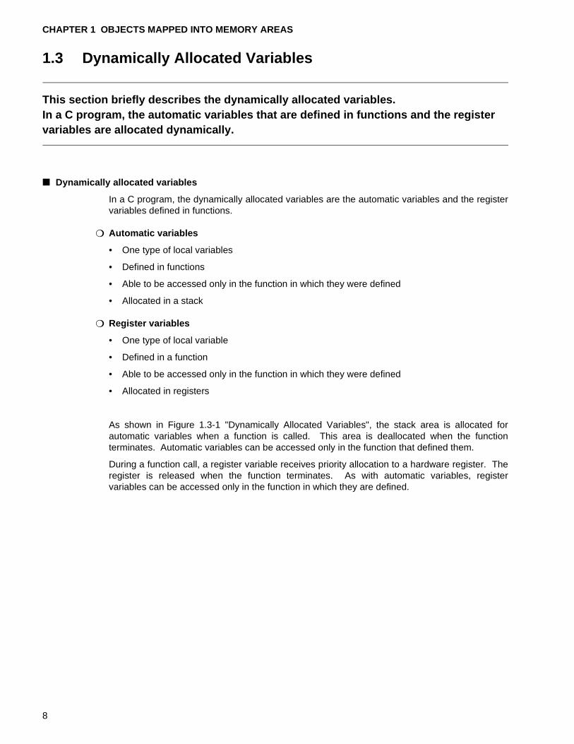
As shown in Figure 1.3-1 "Dynamically Allocated Variables", the stack area is allocated forautomatic variables when a function is called. This area is deallocated when the functionterminates. Automatic variables can be accessed only in the function that defined them.
During a function call, a register variable receives priority allocation to a hardware register. Theregister is released when the function terminates. As with automatic variables, registervariables can be accessed only in the function in which they are defined.
8
1.3 Dynamically Allocated Variables
Figure 1.3-1 Dynamically Allocated Variables
userpidh'xxxx
SP
high
RW3
RW3
h'xxxx
high
SP
low
low
h'xxxx
high
i
prevnext
iuserpid
dummy
moji [4]moji [3]moji [2]moji [1]moji [0]
SP
low
high
SPh'xxxx
Dynamically allocated variables
Auto variables - Allocated on the stack at function execution- The stack area is deallocated when the function terminates.Register variables- Allocated to a hardware register at function execution- The register is released when the function terminates
Stack status when the functioninit( ) terminates
Status of stack at start offunction init( )
Autovariablesdefined inthe functioninit( )
Return addressPrevious RW3
Previous RW3Return address
Stack status when the functionstart( ) terminates
Autovariablesdefined instart( )
Stack status when functionstart( ) starts
9
CHAPTER 1 OBJECTS MAPPED INTO MEMORY AREAS
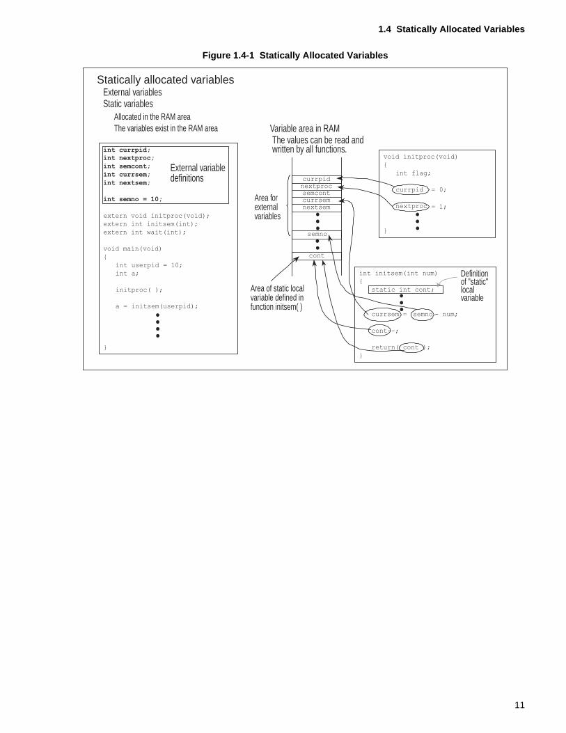
1.4 Statically Allocated Variables
This section briefly describes the statically allocated variables.In a C program, external variables that are defined outside a function and variables declared as "static" are both allocated statically in a fixed RAM area.
■ Statically Allocated Variables
In a C program, external variables that are defined outside a function and variables declared as"static" are both allocated statically.
❍ External variables
• Defined outside a function
• Able to be accessed from the entire module
• Statically allocated in memory
❍ Static variables
• Able to be accessed only within their defined scope
• Statically allocated in memory
As shown in Figure 1.4-1 "Statically Allocated Variables", external variables and static variablesare allocated in a fixed RAM area at program execution. External variables can be accessed byall functions. Static variables are valid only within their defined scope. For details of staticvariables, see Section 2.4 "Variables Declared as "static" and Their Variable Area".
10
1.4 Statically Allocated Variables
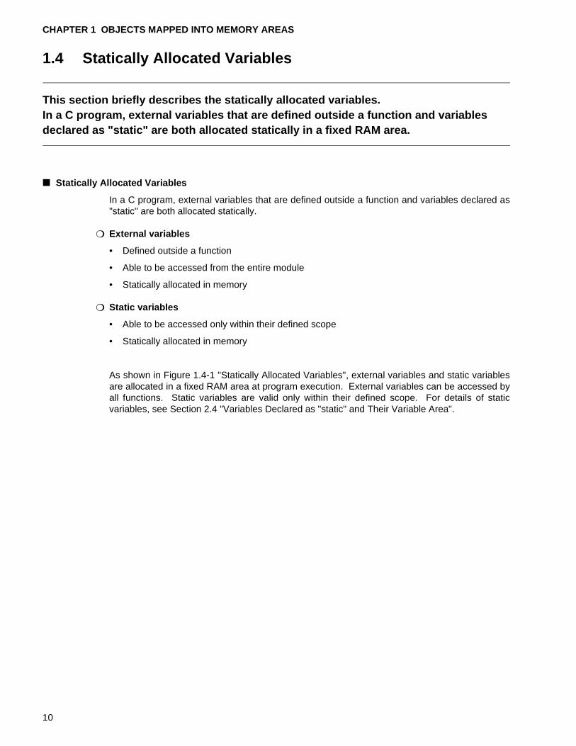
Figure 1.4-1 Statically Allocated Variables
Statically allocated variablesExternal variables Static variables
Allocated in the RAM areaThe variables exist in the RAM area
External variabledefinitions
Variable area in RAMThe values can be read andwritten by all functions.
Area forexternalvariables
Area of static localvariable defined infunction initsem( )
Definitionof "static"local variable
semno
cont
currpidnextprocsemcontcurrsemnextsem
int currpid;
int nextproc;
int semcont;
int currsem;
int nextsem;
int semno = 10;
extern void initproc(void);
extern int initsem(int);
extern int wait(int);
void main(void)
{
int userpid = 10;
int a;
initproc( );
a = initsem(userpid);
}
void initproc(void)
{
int flag;
currpid = 0;
nextproc = 1;
}
int initsem(int num)
{
static int cont;
currsem = semno - num;
cont--;
return( cont );
}
11
CHAPTER 1 OBJECTS MAPPED INTO MEMORY AREAS
12
CHAPTER 2 VARIABLE DEFINITIONS AND VARIABLE AREAS
This chapter briefly describes the variable definitions and variable areas to which variables are output as a result of compilation. It then describes the relationship between initial values and the variable areas used for variables. The chapter also describes variables declared as "static," which is one type of static variables that have a special format.
2.1 "External Variables and their Variable Area"
2.2 "Initial Values and Variable Area for External Variables"
2.3 "Initialized Variables and Initialization at Execution"
2.4 "Variables Declared as "static" and their Variable Area"
13
CHAPTER 2 VARIABLE DEFINITIONS AND VARIABLE AREAS
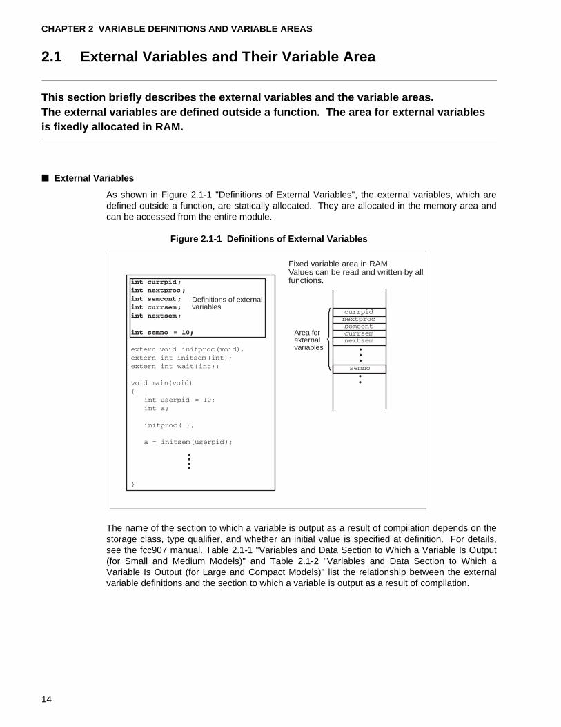
2.1 External Variables and Their Variable Area
This section briefly describes the external variables and the variable areas.The external variables are defined outside a function. The area for external variables is fixedly allocated in RAM.
■ External Variables
As shown in Figure 2.1-1 "Definitions of External Variables", the external variables, which aredefined outside a function, are statically allocated. They are allocated in the memory area andcan be accessed from the entire module.
Figure 2.1-1 Definitions of External Variables
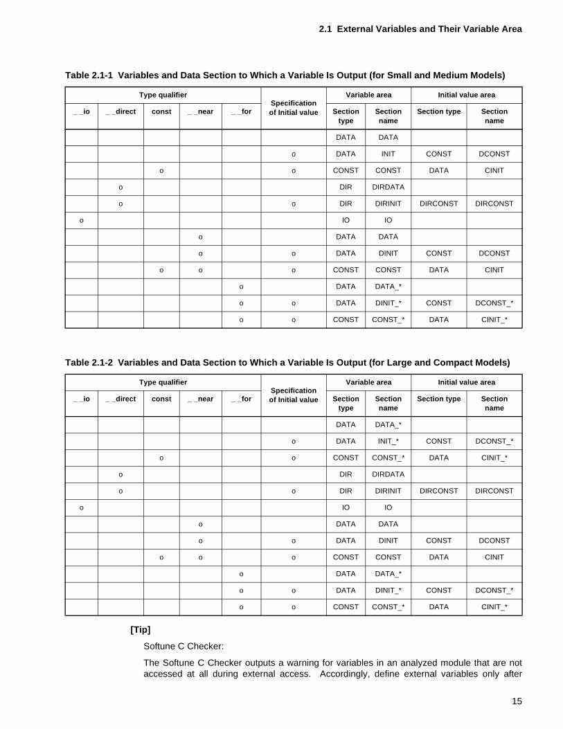
The name of the section to which a variable is output as a result of compilation depends on thestorage class, type qualifier, and whether an initial value is specified at definition. For details,see the fcc907 manual. Table 2.1-1 "Variables and Data Section to Which a Variable Is Output(for Small and Medium Models)" and Table 2.1-2 "Variables and Data Section to Which aVariable Is Output (for Large and Compact Models)" list the relationship between the externalvariable definitions and the section to which a variable is output as a result of compilation.
Definitions of externalvariables
Fixed variable area in RAMValues can be read and written by allfunctions.
Area forexternalvariables
14
2.1 External Variables and Their Variable Area
[Tip]
Softune C Checker:
The Softune C Checker outputs a warning for variables in an analyzed module that are notaccessed at all during external access. Accordingly, define external variables only after
Table 2.1-1 Variables and Data Section to Which a Variable Is Output (for Small and Medium Models)
Type qualifierSpecification of Initial value
Variable area Initial value area
_ _io _ _direct const _ _near _ _for Section type
Section name
Section type Section name
DATA DATA
o DATA INIT CONST DCONST
o o CONST CONST DATA CINIT
o DIR DIRDATA
o o DIR DIRINIT DIRCONST DIRCONST
o IO IO
o DATA DATA
o o DATA DINIT CONST DCONST
o o o CONST CONST DATA CINIT
o DATA DATA_*
o o DATA DINIT_* CONST DCONST_*
o o CONST CONST_* DATA CINIT_*
Table 2.1-2 Variables and Data Section to Which a Variable Is Output (for Large and Compact Models)
Type qualifierSpecification of Initial value
Variable area Initial value area
_ _io _ _direct const _ _near _ _for Section type
Section name
Section type Section name
DATA DATA_*
o DATA INIT_* CONST DCONST_*
o o CONST CONST_* DATA CINIT_*
o DIR DIRDATA
o o DIR DIRINIT DIRCONST DIRCONST
o IO IO
o DATA DATA
o o DATA DINIT CONST DCONST
o o o CONST CONST DATA CINIT
o DATA DATA_*
o o DATA DINIT_* CONST DCONST_*
o o CONST CONST_* DATA CINIT_*
15
CHAPTER 2 VARIABLE DEFINITIONS AND VARIABLE AREAS
verifying the intended scope. Meaningless access declarations make a program look poorlywritten.
16
2.2 Initial Values and Variable Area for External Variables
2.2 Initial Values and Variable Area for External Variables
This section describes the relationship between the initial values and variable areas of external variables.In fcc907, when an initial value is specified at definition of an external variable, variable area is allocated in both the ROM and RAM areas.
■ Initial Values and the Variable Area for External Variables
Variables can be classified into the following three types according to how initialization ishandled when the variables are defined. Whether an initial value is required depends on theway in which the variable is to be used.
Initial value not required
No initial value specification (The variable does not need to be initialized to 0.)
Initial value 0
No initial value specification (The variable must be initialized to 0.)
Initial value other than 0
An initial value other than 0 is specified
The fcc907, handles two types of external variables: external variables for which an initializationvalue is specified when they are defined (initialized variables hereafter) and external variablesfor which no initialization value is specified when they are defined (uninitialized variableshereafter).
The variable area and initial value area sections are output for initialized variables. Foruninitialized variables, the section variable area are output.
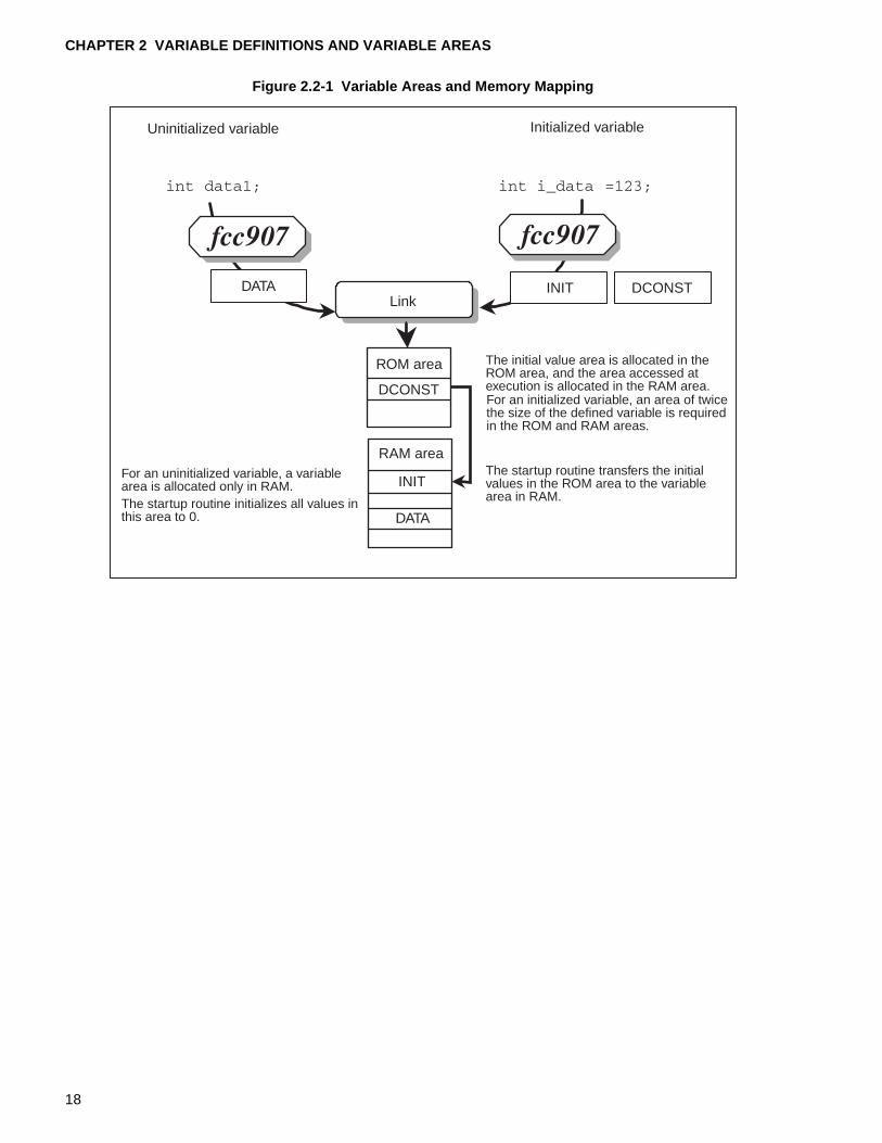
Figure 2.2-1 "Variable Areas and Memory Mapping" shows the relationship between the outputsections and memory mapping for initialized and uninitialized variables. For initialized variables,a variable area is allocated in both ROM and RAM. The RAM area values are undefined atsystem start. After system start, the startup routine transfers the initial values from ROM to theRAM variable area. This operation completes initialization of the variable.
For uninitialized variables, a variable area is allocated only in RAM. The value of this RAM areais also undefined at system start. After system start, the startup routine initializes all values inthe variable area for uninitialized variables to 0.
<Notes>
Although the startup routine provided as a sample initializes all uninitialized variables to 0,perform initialization based on the program system that is to be created.
17
CHAPTER 2 VARIABLE DEFINITIONS AND VARIABLE AREAS
Figure 2.2-1 Variable Areas and Memory Mapping
Uninitialized variable Initialized variable
Link
ROM area The initial value area is allocated in theROM area, and the area accessed atexecution is allocated in the RAM area.For an initialized variable, an area of twicethe size of the defined variable is requiredin the ROM and RAM areas.
RAM areaFor an uninitialized variable, a variablearea is allocated only in RAM.The startup routine initializes all values inthis area to 0.
The startup routine transfers the initialvalues in the ROM area to the variablearea in RAM.
INIT
DATA
DATA INIT DCONST
DCONST
18
2.3 Initialized Variables and Initialization at Execution
2.3 Initialized Variables and Initialization at Execution
This section describes initialized variables and the initialization of uninitialized variables at program execution.
■ Initialized Variables and Initialization at Execution
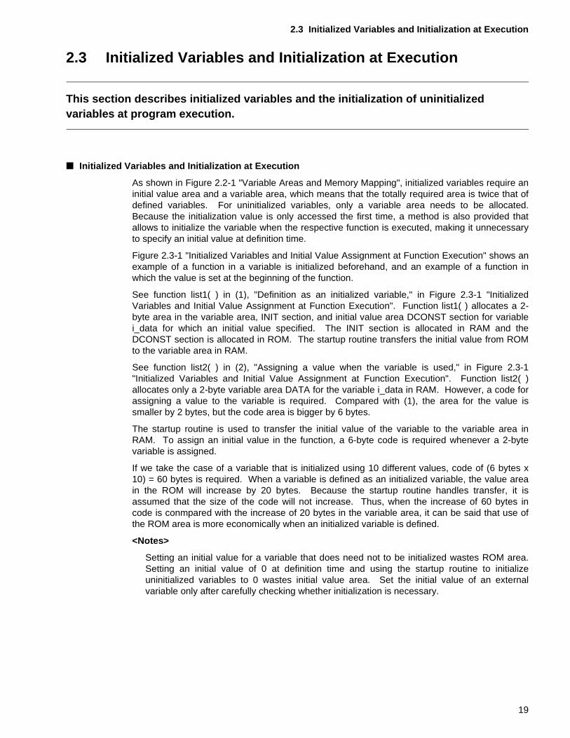
As shown in Figure 2.2-1 "Variable Areas and Memory Mapping", initialized variables require aninitial value area and a variable area, which means that the totally required area is twice that ofdefined variables. For uninitialized variables, only a variable area needs to be allocated.Because the initialization value is only accessed the first time, a method is also provided thatallows to initialize the variable when the respective function is executed, making it unnecessaryto specify an initial value at definition time.
Figure 2.3-1 "Initialized Variables and Initial Value Assignment at Function Execution" shows anexample of a function in a variable is initialized beforehand, and an example of a function inwhich the value is set at the beginning of the function.
See function list1( ) in (1), "Definition as an initialized variable," in Figure 2.3-1 "InitializedVariables and Initial Value Assignment at Function Execution". Function list1( ) allocates a 2-byte area in the variable area, INIT section, and initial value area DCONST section for variablei_data for which an initial value specified. The INIT section is allocated in RAM and theDCONST section is allocated in ROM. The startup routine transfers the initial value from ROMto the variable area in RAM.
See function list2( ) in (2), "Assigning a value when the variable is used," in Figure 2.3-1"Initialized Variables and Initial Value Assignment at Function Execution". Function list2( )allocates only a 2-byte variable area DATA for the variable i_data in RAM. However, a code forassigning a value to the variable is required. Compared with (1), the area for the value issmaller by 2 bytes, but the code area is bigger by 6 bytes.
The startup routine is used to transfer the initial value of the variable to the variable area inRAM. To assign an initial value in the function, a 6-byte code is required whenever a 2-bytevariable is assigned.
If we take the case of a variable that is initialized using 10 different values, code of (6 bytes x10) = 60 bytes is required. When a variable is defined as an initialized variable, the value areain the ROM will increase by 20 bytes. Because the startup routine handles transfer, it isassumed that the size of the code will not increase. Thus, when the increase of 60 bytes incode is conmpared with the increase of 20 bytes in the variable area, it can be said that use ofthe ROM area is more economically when an initialized variable is defined.
<Notes>
Setting an initial value for a variable that does need not to be initialized wastes ROM area.Setting an initial value of 0 at definition time and using the startup routine to initializeuninitialized variables to 0 wastes initial value area. Set the initial value of an externalvariable only after carefully checking whether initialization is necessary.
19
CHAPTER 2 VARIABLE DEFINITIONS AND VARIABLE AREAS
Figure 2.3-1 Initialized Variables and Initial Value Assignment at Function Execution
(1) Definition as initialized variable (2) Assigning a value when the variableis used
The size of the object to be generated differs.
The initial value area DCONST and variable area INIT are output.
The variable area DATA is output.Because code is generated for assigning thevalue in the function, the size of the code areaincreases.
_
20
2.4 Variables Declared as "static" and Their Variable Area
2.4 Variables Declared as "static" and Their Variable Area
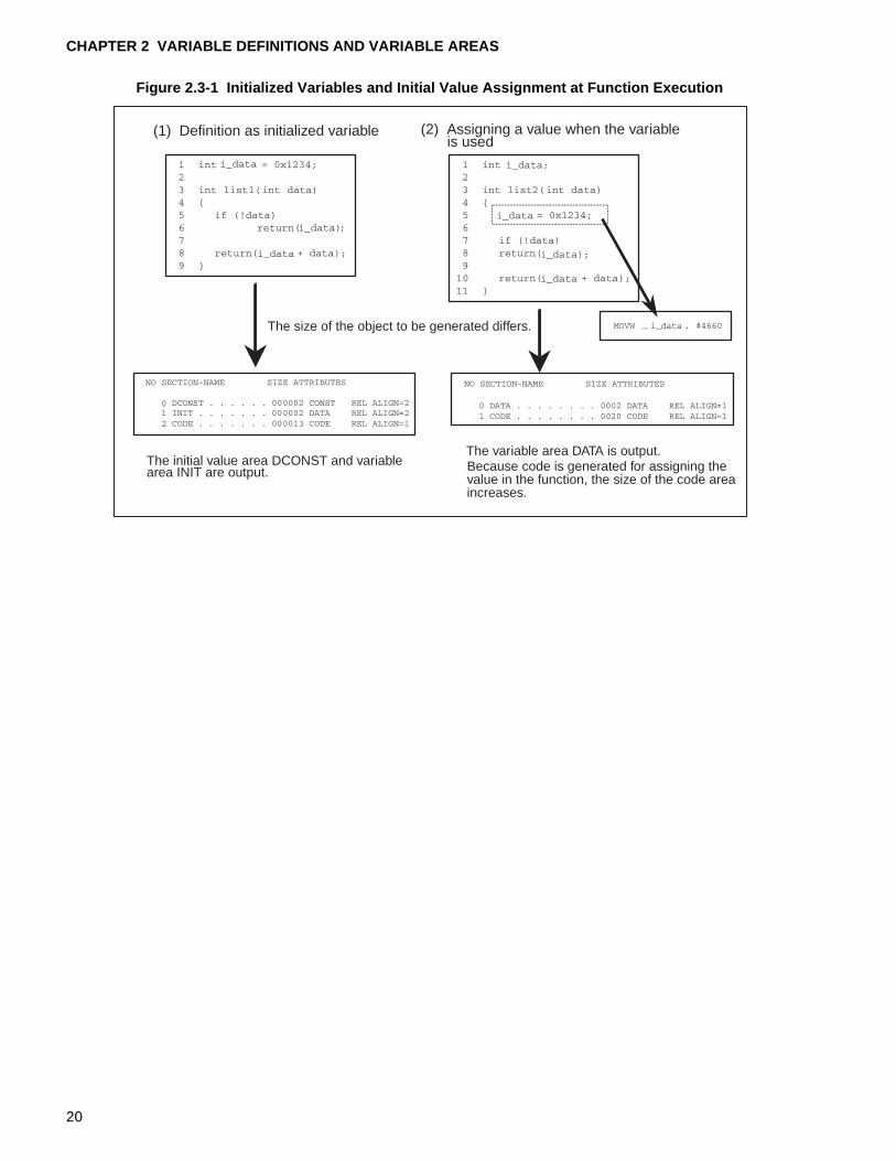
This section briefly describes variables declared as "static" and the variable area they require. Variables declared as "static" are only one type of variables that are allocated statically.For a variable declared as "static", area in RAM is allocated for the variable statically. The scope of variables declared as "static" depends on where they are defined. A variable that is defined outside a function is referred to as a static global variable. A variable that is defined inside a function is referred to as a static local variable. Even if the module or function where the variables are defined terminates, the values are retained in the variable area within RAM.
■ Variables Declared as "static" and Their Variable Area
Whether a variable is dynamically or statically allocated depends on where it is defined. Areafor external variables is allocated in RAM if the variable has been defined outside a function.Because the area is always present in RAM, the area can be accessed from the entire module.
For a variable declared as "static", area in RAM is allocated for the variable statically. However,as shown in Figure 2.4-1 "Scope of Variables Declared as "static"", the scope of the variabledepends on where it is defined. A variable that is defined outside a function is referred to as astatic global variable. A variable that is defined within a function is referred to as a static localvariable. Static global and static local variables are output to the same section for externalvariables.
21
CHAPTER 2 VARIABLE DEFINITIONS AND VARIABLE AREAS
Figure 2.4-1 Scope of Variables Declared as "static"
Section 2.4.1 "Example of Function with Static Global Variable" provides an example of afunction that uses a static global variable. Section 2.4.2 "Example of a Function with a StaticLocal Variable" provides an example of a function that uses a static local variable.
The scope of a variable declared as "static" depends on where the variable is defined. Even ifthe module or function where the variable is defined terminates, the value is retained in thevariable area in RAM.
The advantage of using a variable defined as a static local variable in a function as a countervariable for the number of times the function is called is that the value will be retained. On theother hand, if a variable declared as "static" is used for a task where the value need not beretained, RAM area will be used inefficiently. Define a static variable only after carefullyinvestigating whether this is necessary.
[Tip]
Softune C Checker:
The Softune C Checker outputs a warning for variables that have been declared as "static" inthe analyzed module, but have not been accessed at all. Accordingly, carefully check thescope of variables and define variables as static variables only when necessary.
In addition, for Variables declared as "static" for which no initial value has been specified, awarning requesting that the variables be initialized will be output. If necessary, specify aninitial value.
Can only be accessed from withinthe module in this source file. Cannot be accessed from othermodules. Area is allocated in RAM.
Valid inside this function.Area is allocated in RAM.
Different variablesDifferent areas are allocated for these variables.
extern int main(void);
extern int inittime(void);
extern int init(int);
extern int numproc;
int currpid;
int semno;
int nextsem = 0;
static int nextproc = 100;
int null(void)
{
int userpid = 10;
inittime();
currpid = init(userpid);
nextsem++;
semno = 100;
return(semno);
}
int init(int pid)
{
static int num = 50;
int i = 0;
int j;
return(num--);
}
extern int null(void);
extern int currpid;
extern int semno;
extern int nextsem;
int numproc = 100;
static int nextproc = 50;
void start(void)
{
int pid = 0;
if (null() > 0)
pid++;
}
Static global variable
Static global variable
Static local variable
22
2.4 Variables Declared as "static" and Their Variable Area
2.4.1 Example of Function with Static Global Variable
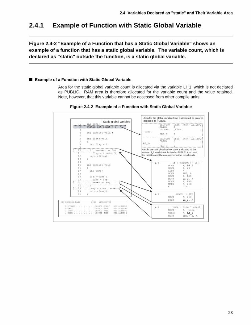
Figure 2.4-2 "Example of a Function that has a Static Global Variable" shows an example of a function that has a static global variable. The variable count, which is declared as "static" outside the function, is a static global variable.
■ Example of a Function with Static Global Variable
Area for the static global variable count is allocated via the variable LI_1, which is not declaredas PUBLIC. RAM area is therefore allocated for the variable count and the value retained.Note, however, that this variable cannot be accessed from other compile units.
Figure 2.4-2 Example of a Function with Static Global Variable
Static global variable
Area for the static global variable count is allocated via thevariable LI_1, which is not declared as PUBLIC. As a result,the variable cannot be accessed from other compile units.
Area for the global variable time is allocated as an area declared as PUBLIC.
1 int time;
2 static int count = 0;
3
4 int timeint(void);
5
6 int list3(void)
7 {
8 int flag = 0;9
10 if (++count >= 60)
11 flag = timeint();
12 return(flag);
13 }
14
15 int timeint(void)
16 {
17 int temp;
18
19 if(!--time){
20 time = 10;
21 count -= 60;
22 }
23 temp = time * count;
24 return(temp);
25 }
;;;; if (++count >= 60)MOVW A, LI_1MOVN A, #1ADDW AMOVW RW0, AMOVW A, RW0MOVW LI_1, AMOVW A, RW0CMPW A, #60BLT L_23
;;;; count -= 60;
MOVW A, #60
SUBW LI_1, A
;;;; temp = time * count;
MOVW A, _time
MULUW A, LI_1MOVW @RW3+-2, A
.SECTION DATA, DATA, ALIGN=2
.ALIGN 2
.GLOBAL _time_time:
.RES.B 2
.SECTION INIT, DATA, ALIGN=2
.ALIGN 2LI_1:
.RES.H 1
NO SECTION-NAME SIZE ATTRIBUTES
0 DCONST . . . . . . . 000002 CONST REL ALIGN=21 DATA . . . . . . . . 000002 DATA REL ALIGN=22 INIT . . . . . . . . 000002 DATA REL ALIGN=23 CODE . . . . . . . . 00004D CODE REL ALIGN=1
23

CHAPTER 2 VARIABLE DEFINITIONS AND VARIABLE AREAS
2.4.2 Example of aunction with Static Local Variable
Figure 2.4-3 "Example of a Function with Static Local Variable" shows an example of a function that has a static local variable. The variable count, which is declared as "static" in the function, is a static local variable.
■ Example of a Function with Static Local Variable
Area for the static local variable count defined in function list4( ) is allocated via the variableLI_1, which is not declared as PUBLIC.
Similarly, area for the static local variable count defined in function timeint( ) is allocated via thevariable LI_2, which also is not declared as PUBLIC. A separate area in RAM is allocated foreach of the static local variables "count" and their values are retained. The scope of thesevariables is within the defined function. The variables cannot be accessed from other functionseven within the same compilation unit.
Figure 2.4-3 Example of a Function with Static Local Variable
Static local variable
Static local variable
Area for the static local variable count of function list4( ) is allocated via the variable LI_1, which is not declared as PUBLIC.Area for the static local variable count of function timeint2( ) is allocated via the variable LI_2, which is not declared as PUBLIC.
1 int time;
2
3 int timeint2(void);
4
5 int list4(void)
6 {
7 int flag = 0;
8 static int count = 0;9
10 if (++count >= 60)
11 flag = timeint2();
12 return(flag);
13 }
1415 int timeint2(void)
16 {
17 int temp;
18 static int count = 1000;19
20 if(!--time){
21 time = 10;
22 count -= 60;
23 }
24 temp = time * count;
25 return(temp);
26 }
;;; if (++count >= 60)MOVW A, LI_1MOVN A, #1ADDW AMOVW RW0, AMOVW A, RW0MOVW LI_1, AMOVW A, RW0CMPW A, #60BLT L_23
;;;; count -= 60;
MOVW A, #60
SUBW LI_2, A
;;;; temp = time * count;
MOVW A, _time
MULUW A, LI_2
MOVW @RW3+-2, A
.SECTION DATA, DATA, ALIGN=2
.ALIGN 2
.GLOBAL _time_time:
.RES.B 2
.SECTION INIT, DATA, ALIGN=2
.ALIGN 2LI_2:
.RES.H 1
.ALIGN 2LI_1:
.RES.H 1
NO SECTION-NAME SIZE ATTRIBUTES
0 DCONST . . . . . . 000004 CONST REL ALIGN=2
1 DATA . . . . . . . 000002 DATA REL ALIGN=2
2 INIT . . . . . . . 000004 DATA REL ALIGN=2
3 CODE . . . . . . . 00004D CODE REL ALIGN=1
24
CHAPTER 3 READ-ONLY VARIABLES AND THEIR VARIABLE AREA
This chapter describes how to use read-only variables.A value is read or written for a variable at execution. Therefore, the variable areas are mapped into RAM areas, which can be read and written. However, there are variables that are at execution only read and do not need to be changed. Examples for this type of variable are messages, such as opening or error messages. Mapping variables that are read-only in RAM areas in the same way as normal external variables has the result that these RAM areas are only read at execution. As a result, valuable RAM space will be wasted. This chapter describes two methods for reducing the required areas within RAM.
3.1 "Numeric Constants and #define Definition"
3.2 "Defining Variables Using the const Type Qualifier"
25
CHAPTER 3 READ-ONLY VARIABLES AND THEIR VARIABLE AREA
3.1 Numeric Constants and #define Definition
This section describes how to use the #define definition to define read-only variables as numeric constants.Because this method does not allocate variable areas, RAM area usage can be reduced.
■ Numeric Constants and #define Definition
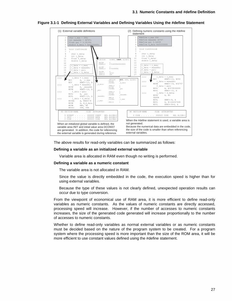
Figure 3.1-1 "Defining External Variables and Defining Variables Using the #define Statement"shows an example of defining read-only variables as initialized external variables and using the#define statement to define the read-only variables as numeric constants in a macro definition.
See function list5( ) of (1), "External variable definitions," in Figure 3.1-1 "Defining ExternalVariables and Defining Variables Using the #define Statement". Because initialized variableshave been defined for function list5( ), the variable area INIT section and initial value areaDCONST section are generated. At linkage, the initial value area DCONST section is mappedinto the ROM area. The variable area INIT section is mapped into the RAM area. The startuproutine transfers the initial value in the ROM area to the RAM area. The following variables aredefined for function list5( ):
• char-type variable (1 byte) c_max
• int-type variable (2 bytes) maxaddr
• float-type variable (4 bytes) pai
• double-type variable (8 bytes) d_data
The variable area INIT is allocated in the RAM area for these variables. Read-only variablesare not written to at execution. From the viewpoint of economical use of the RAM area, this 15-byte variable area will be wasted.
The value of an external variable is referenced on the basis of the address of the externalvariable.
As shown below, the size of the code generated at reference depends on the variable type.
• To reference a char-type (1 byte) variable: 6 bytes
• To reference an int-type (2 bytes) variable: 5 bytes
• To reference a float-type (4 bytes) variable: 7 bytes
• To reference a double-type (8 bytes) variable: 11 bytes
See the function list6( ) of (2), "Defining numeric constants using the #define statement," inFigure 3.1-1 "Defining External Variables and Defining Variables Using the #define Statement".Function list6( ) defines c_max, maxaddr, pai, and d_data using the macro definition of the#define statement. The value of the macro-defined numeric constant is embedded in the code,and a variable area is not generated. Because the code for referencing the external variable isnot generated, the total code length will be relatively short. The execution speed will also beincreased. The code to be generated depends on the numeric constant.
Macro-defined variables have no type. Therefore, type conversion may be performed atassignment depending on the type of the variable to be assigned. This can lead to unexpectedresults.
26
3.1 Numeric Constants and #define Definition
Figure 3.1-1 Defining External Variables and Defining Variables Using the #define Statement
The above results for read-only variables can be summarized as follows:
Defining a variable as an initialized external variable
Variable area is allocated in RAM even though no writing is performed.
Defining a variable as a numeric constant
The variable area is not allocated in RAM.
Since the value is directly embedded in the code, the execution speed is higher than forusing external variables.
Because the type of these values is not clearly defined, unexpected operation results canoccur due to type conversion.
From the viewpoint of economical use of RAM area, it is more efficient to define read-onlyvariables as numeric constants. As the values of numeric constants are directly accessed,processing speed will increase. However, if the number of accesses to numeric constantsincreases, the size of the generated code generated will increase proportionally to the numberof accesses to numeric constants.
Whether to define read-only variables as normal external variables or as numeric constantsmust be decided based on the nature of the program system to be created. For a programsystem where the processing speed is more important than the size of the ROM area, it will bemore efficient to use constant values defined using the #define statement.
(1) External variable definitions (2) Defining numeric constants using the #define
When an initialized global variable is defined, the variable area INIT and initial value area DCONST are generated. In addition, the code for referencing the external variable is generated during reference.
When the #define statement is used, a variable area is not generated.Because the numerical data are embedded in the code,the size of the code is smaller than when referencingexternal variables.
statement1 char c_max = 250;
2 int maxaddr = 32767;
3 float pai = 3.14159;
4 double d_data = 0xffff0000;
5
6 void list5(void)
7 {
8 char c_data;
9 int i_data;
10 float f_data;
11 double l_data;
12
13 c_data = c_max;
14 i_data = maxaddr;
15 f_data = pai;
16 l_data = d_data;
17 }
1 #define c_max 250
2 #define maxaddr 32767
3 #define pai 3.14159
4 #define d_data 0xffff0000
5
6 void list6(void)
7 {
8 char c_data;
9 int i_data;
10 float f_data;
11 double l_data;
12
13 c_data = c_max;
14 i_data = maxaddr;
15 f_data = pai;
16 l_data = d_data;
17 }
;;;; c_data = c_max;
MOV A, _c_max
MOV @RW3+-15, A
;;;; i_data = maxaddr;
MOVW A, _maxaddr
MOVW @RW3+-14, A
;;;; f_data = pai;
MOVL A, _pai
MOVL @RW3+-12, A
;;;; l_data = d_data;
MOVEA A, @RW3+-8
MOVW A, #_d_data
MOVW RW0, #8
MOVSI DTB, DTB
;;;; c_data = c_max;
MOV @RW3+-15, #250
;;;; i_data = maxaddr;
MOVW @RW3+-14, #32767
;;;; f_data = pai;
MOVL A, #1078530000
MOVL @RW3+-12, A
;;;; l_data = d_data;
MOVN A, #0
ZEXTW
MOVL @RW3+-8, A
MOVL A, #1106247648
MOVL @RW3+-8+4, A
NO SECTION-NAME SIZE ATTRIBUTES
0 DCONST . . . . . 00000F CONST REL ALIGN=21 INIT . . . . . . 00000F DATA REL ALIGN=22 CODE . . . . . . 000025 CODE REL ALIGN=1
NO SECTION-NAME SIZE ATTRIBUTES
0 CODE . . . . . . 000022 CODE REL ALIGN=1
.SECTION DCONST, CONST, ALIGN=2
.ALIGN 2
.FDATA.D H'41EFFFE000000000
.ALIGN 2
.FDATA.S H'40490FD0
.ALIGN 2
.DATA.H 32767
.DATA.B 250
.SECTION INIT, DATA, ALIGN=2
.ALIGN 2
.GLOBAL _d_data_d_data:
.FRES.D 1
.ALIGN 2
.GLOBAL _pai_pai:
.FRES.S 1
.ALIGN 2
.GLOBAL _maxaddr_maxaddr:
.RES.H 1
.GLOBAL _c_max_c_max:
.RES.B 1
27
CHAPTER 3 READ-ONLY VARIABLES AND THEIR VARIABLE AREA
3.2 Defining Variables Using the const Type Qualifier
This section describes how to define read-only variables using the "const" type qualifier.Because this method directly accesses the initial value areas allocated in ROM, the size of the RAM area can be reduced.
■ Defining Variables Using the "const" Type Qualifier
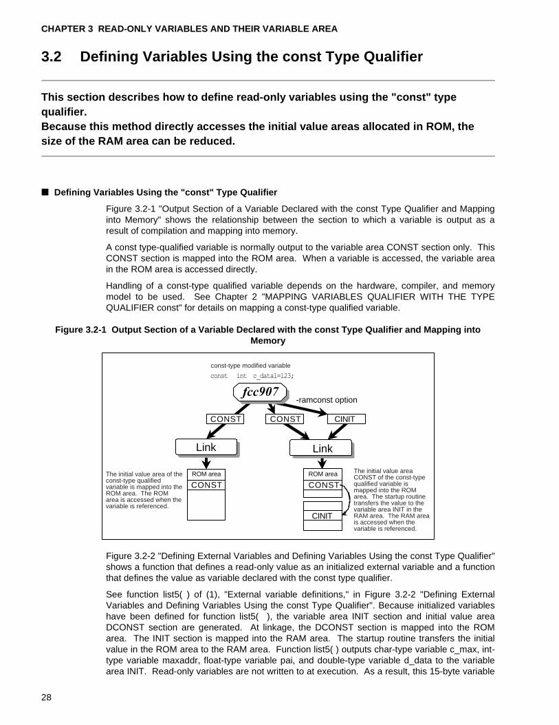
Figure 3.2-1 "Output Section of a Variable Declared with the const Type Qualifier and Mappinginto Memory" shows the relationship between the section to which a variable is output as aresult of compilation and mapping into memory.
A const type-qualified variable is normally output to the variable area CONST section only. ThisCONST section is mapped into the ROM area. When a variable is accessed, the variable areain the ROM area is accessed directly.
Handling of a const-type qualified variable depends on the hardware, compiler, and memorymodel to be used. See Chapter 2 "MAPPING VARIABLES QUALIFIER WITH THE TYPEQUALIFIER const" for details on mapping a const-type qualified variable.
Figure 3.2-1 Output Section of a Variable Declared with the const Type Qualifier and Mapping into Memory
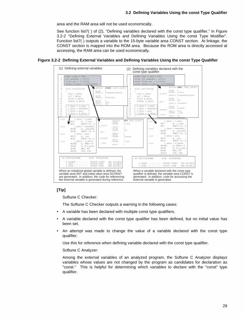
Figure 3.2-2 "Defining External Variables and Defining Variables Using the const Type Qualifier"shows a function that defines a read-only value as an initialized external variable and a functionthat defines the value as variable declared with the const type qualifier.
See function list5( ) of (1), "External variable definitions," in Figure 3.2-2 "Defining ExternalVariables and Defining Variables Using the const Type Qualifier". Because initialized variableshave been defined for function list5( ), the variable area INIT section and initial value areaDCONST section are generated. At linkage, the DCONST section is mapped into the ROMarea. The INIT section is mapped into the RAM area. The startup routine transfers the initialvalue in the ROM area to the RAM area. Function list5( ) outputs char-type variable c_max, int-type variable maxaddr, float-type variable pai, and double-type variable d_data to the variablearea INIT. Read-only variables are not written to at execution. As a result, this 15-byte variable
CONSTROM area
Link
CONSTROM area
Link
CINIT
-ramconst option
CONST CONST CINIT
The initial value area of the const-type qualified variable is mapped into the ROM area. The ROM area is accessed when the variable is referenced.
The initial value area CONST of the const-type qualified variable is mapped into the ROM area. The startup routine transfers the value to the variable area INIT in the RAM area. The RAM area is accessed when the variable is referenced.
const-type modified variable
28
3.2 Defining Variables Using the const Type Qualifier
area and the RAM area will not be used economically.
See function list7( ) of (2), "Defining variables declared with the const type qualifier," in Figure3.2-2 "Defining External Variables and Defining Variables Using the const Type Modifier".Function list7( ) outputs a variable to the 15-byte variable area CONST section. At linkage, theCONST section is mapped into the ROM area. Because the ROM area is directly accessed ataccessing, the RAM area can be used economically.
Figure 3.2-2 Defining External Variables and Defining Variables Using the const Type Qualifier
[Tip]
Softune C Checker:
The Softune C Checker outputs a warning in the following cases:
• A variable has been declared with multiple const type qualifiers.
• A variable declared with the const type qualifier has been defined, but no initial value hasbeen set.
• An attempt was made to change the value of a variable declared with the const typequalifier.
Use this for reference when defining variable declared with the const type qualifier.
Softune C Analyzer:
Among the external variables of an analyzed program, the Softune C Analyzer displaysvariables whose values are not changed by the program as candidates for declaration as"const." This is helpful for determining which variables to declare with the "const" typequalifier.
(1) Defining external variables
When an initialized global variable is defined, the variable area INIT and initial value area DCONST are generated. In addition, the code for referencing the external variable is generated during reference.
When a variable declared with the const typequalifier is defined, the variable area CONST isgenerated. In addition, code for accessing theexternal variable is generated.
Defining variables declared with theconst type qualifier
(2)
1 char c_max = 250;
2 int maxaddr = 32767;
3 float pai = 3.14159;
4 double d_data = 0xffff0000;
5
6 void list5(void)
7 {
8 char c_data;
9 int i_data;
10 float f_data;
11 double l_data;
12
13 c_data = c_max;
14 i_data = maxaddr;
15 f_data = pai;
16 l_data = d_data;
17 }
;;;; c_data = c_max;
MOV A, _c_max
MOV @RW3+-15, A
;;;; i_data = maxaddr;
MOVW A, _maxaddr
MOVW @RW3+-14, A
;;;; f_data = pai;
MOVL A, _pai
MOVL @RW3+-12, A
;;;; l_data = d_data;
MOVEA A, @RW3+-8
MOVW A, #_d_data
MOVW RW0, #8
MOVSI DTB, DTB
NO SECTION-NAME SIZE ATTRIBUTES
0 DCONST . . . . . 00000F CONST REL ALIGN=21 INIT . . . . . . 00000F DATA REL ALIGN=22 CODE . . . . . . 000025 CODE REL ALIGN=1
1 const char c_max = 250;
2 const int maxaddr = 32767;
3 const float pai = 3.14159;
4 const double d_data = 0xffff0000;
5
6 void list7(void)
7 {
8 char c_data;
9 int i_data;
10 float f_data;
11 double l_data;
12
13 c_data = c_max;
14 i_data = maxaddr;
15 f_data = pai;
16 l_data = d_data;
17 }
;;;; c_data = c_max;
MOV A, _c_max
MOV @RW3+-15, A
;;;; i_data = maxaddr;
MOVW A, _maxaddr
MOVW @RW3+-14, A
;;;; f_data = pai;
MOVL A, _pai
MOVL @RW3+-12, A
;;;; l_data = d_data;
MOVEA A, @RW3+-8
MOVW A, #_d_data
MOVW RW0, #8
MOVSI DTB, DTB
NO SECTION-NAME SIZE ATTRIBUTES
0 CONST . . . . . 00000F CONST REL ALIGN=2
1 CODE . . . . . . 000025 CODE REL ALIGN=1
.SECTION DCONST, CONST, ALIGN=2
.ALIGN 2
.FDATA.D H'41EFFFE000000000
.ALIGN 2
.FDATA.S H'40490FD0
.ALIGN 2
.DATA.H 32767
.DATA.B 250
.SECTION INIT, DATA, ALIGN=2
.ALIGN 2
.GLOBAL _d_data_d_data:
.FRES.D 1
.ALIGN 2
.GLOBAL _pai_pai:
.FRES.S 1
.ALIGN 2
.GLOBAL _maxaddr_maxaddr:
.RES.H 1
.GLOBAL _c_max_c_max:
.RES.B 1
.SECTION CONST, CONST, ALIGN=2
.ALIGN 2
.GLOBAL _d_data_d_data:
.FDATA.D H'41EFFFE000000000
.ALIGN 2
.GLOBAL _pai_pai:
.FDATA.S H'40490FD0
.ALIGN 2
.GLOBAL _maxaddr_maxaddr:
.DATA.H 32767
.GLOBAL _c_max_c_max:
.DATA.B 250
29
CHAPTER 3 READ-ONLY VARIABLES AND THEIR VARIABLE AREA
30
CHAPTER 4 USING AUTOMATIC VARIABLES TO REDUCE THE VARIABLE AREA
This chapter describes how to reduce variable areas using "automatic" variables.For automatic variables, the variable areas are allocated on the stack when the function is called. The variable areas are deallocated at the termination of the function. Variables that are referenced only from within the function are defined as automatic variables to reduce the variable areas.
4.1 "Automatic Variables and Statically Allocated Variables"
4.2 "Using Automatic Variables"
31
CHAPTER 4 USING AUTOMATIC VARIABLES TO REDUCE THE VARIABLE AREA
4.1 Automatic Variables and Statically Allocated Variables
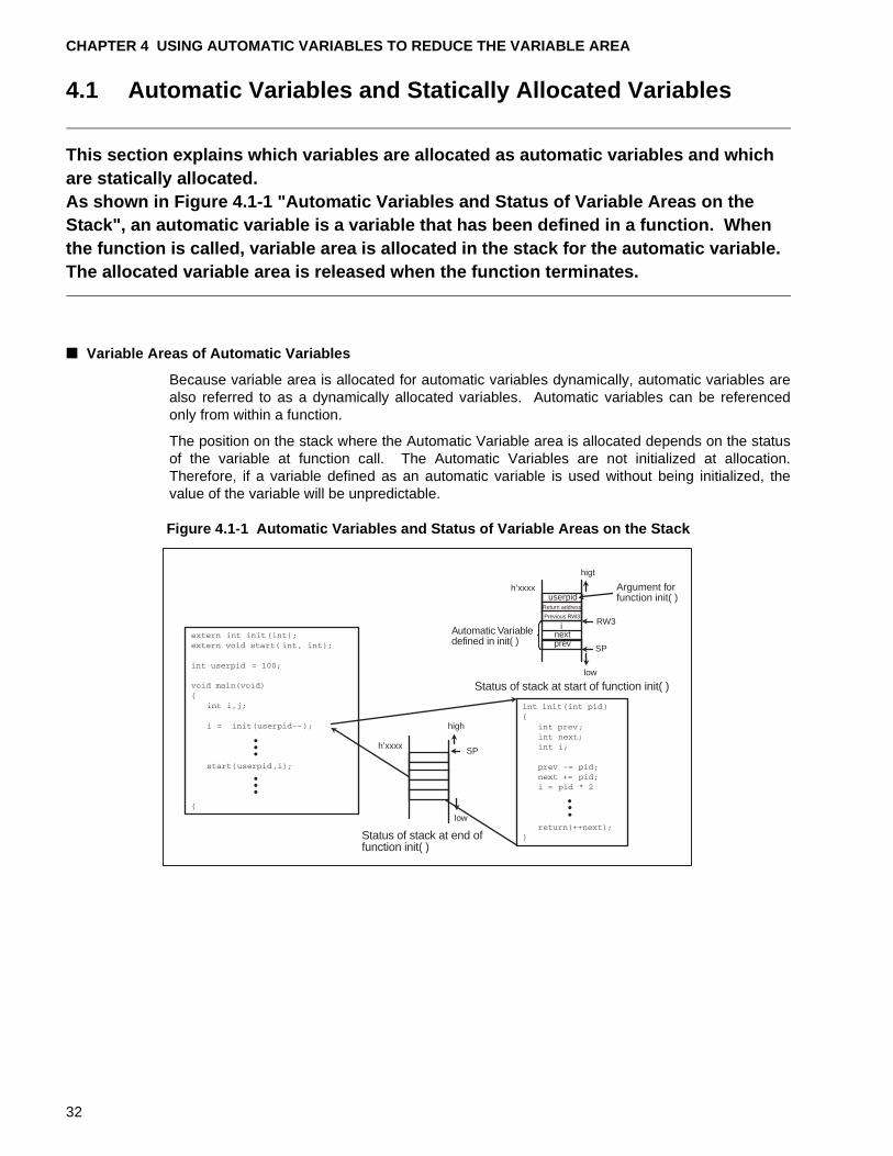
This section explains which variables are allocated as automatic variables and which are statically allocated.As shown in Figure 4.1-1 "Automatic Variables and Status of Variable Areas on the Stack", an automatic variable is a variable that has been defined in a function. When the function is called, variable area is allocated in the stack for the automatic variable. The allocated variable area is released when the function terminates.
■ Variable Areas of Automatic Variables
Because variable area is allocated for automatic variables dynamically, automatic variables arealso referred to as a dynamically allocated variables. Automatic variables can be referencedonly from within a function.
The position on the stack where the Automatic Variable area is allocated depends on the statusof the variable at function call. The Automatic Variables are not initialized at allocation.Therefore, if a variable defined as an automatic variable is used without being initialized, thevalue of the variable will be unpredictable.
Figure 4.1-1 Automatic Variables and Status of Variable Areas on the Stack
h’xxxxSP
low
userpidh’xxxx
low
RW3
SP
inextprev
higt
Argument forfunction init( )
Automatic Variabledefined in init( )
Status of stack at start of function init( )
Status of stack at end of function init( )
Return address
Previous RW3
high
32
4.1 Automatic Variables and Statically Allocated Variables
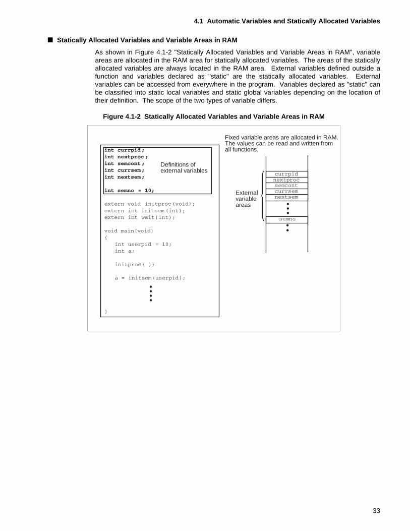
■ Statically Allocated Variables and Variable Areas in RAM
As shown in Figure 4.1-2 "Statically Allocated Variables and Variable Areas in RAM", variableareas are allocated in the RAM area for statically allocated variables. The areas of the staticallyallocated variables are always located in the RAM area. External variables defined outside afunction and variables declared as "static" are the statically allocated variables. Externalvariables can be accessed from everywhere in the program. Variables declared as "static" canbe classified into static local variables and static global variables depending on the location oftheir definition. The scope of the two types of variable differs.
Figure 4.1-2 Statically Allocated Variables and Variable Areas in RAM
Definitions ofexternal variables
Fixed variable areas are allocated in RAM.The values can be read and written fromall functions.
Externalvariableareas
33
CHAPTER 4 USING AUTOMATIC VARIABLES TO REDUCE THE VARIABLE AREA
■ Definition and Scope of Automatic Variables and Statically Allocated Variables
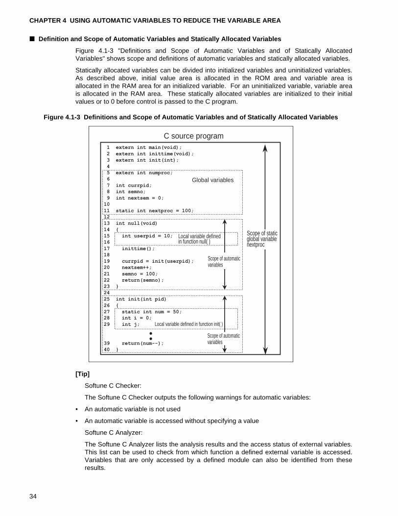
Figure 4.1-3 "Definitions and Scope of Automatic Variables and of Statically AllocatedVariables" shows scope and definitions of automatic variables and statically allocated variables.
Statically allocated variables can be divided into initialized variables and uninitialized variables.As described above, initial value area is allocated in the ROM area and variable area isallocated in the RAM area for an initialized variable. For an uninitialized variable, variable areais allocated in the RAM area. These statically allocated variables are initialized to their initialvalues or to 0 before control is passed to the C program.
Figure 4.1-3 Definitions and Scope of Automatic Variables and of Statically Allocated Variables
[Tip]
Softune C Checker:
The Softune C Checker outputs the following warnings for automatic variables:
• An automatic variable is not used
• An automatic variable is accessed without specifying a value
Softune C Analyzer:
The Softune C Analyzer lists the analysis results and the access status of external variables.This list can be used to check from which function a defined external variable is accessed.Variables that are only accessed by a defined module can also be identified from theseresults.
C source program
Global variables
Local variable definedin function null( )
Local variable defined in function init( )
1 extern int main(void);
2 extern int inittime(void);
3 extern int init(int);
4
5 extern int numproc;
6
7 int currpid;
8 int semno;
9 int nextsem = 0;
10
11 static int nextproc = 100;
12
13 int null(void)
14 {
15 int userpid = 10;
16
17 inittime();
18
19 currpid = init(userpid);
20 nextsem++;
21 semno = 100;
22 return(semno);
23 }
24
25 int init(int pid)
26 {
27 static int num = 50;
28 int i = 0;
29 int j;
39 return(num--);
40 }
Scope of staticglobal variablenextproc
Scope of automaticvariables
Scope of automaticvariables
34
4.2 Using Automatic Variables
4.2 Using Automatic Variables
This section describes the merits of using automatic variables.Reducing the number of external variables and using automatic variables that can only be locally accessed within a function can result in more economical use of the variable area.
■ External Variables and Automatic Variables
External variables can be divided into external variables declared as "const" and those that arenot. Area for external variables that are not declared with the const type qualifier is allocated inRAM. However, careful review of the created program will often find that variables that areaccessed only within a specific function have nevertheless been defined as external variables.Defining a variable whose usage range is restricted as external variable will increase the size ofthe variable area. Reducing the number of external variables and using automatic variables,which can be accessed only from within a function, can result in more economical use of thevariable area.
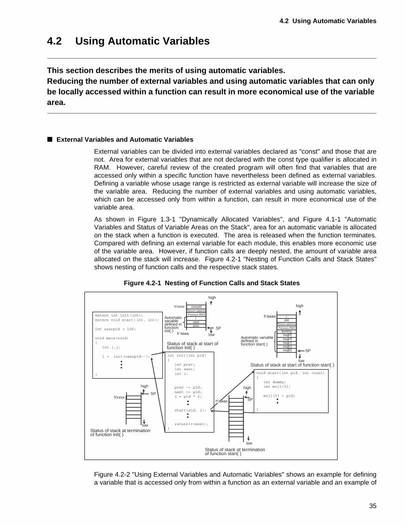
As shown in Figure 1.3-1 "Dynamically Allocated Variables", and Figure 4.1-1 "AutomaticVariables and Status of Variable Areas on the Stack", area for an automatic variable is allocatedon the stack when a function is executed. The area is released when the function terminates.Compared with defining an external variable for each module, this enables more economic useof the variable area. However, if function calls are deeply nested, the amount of variable areaallocated on the stack will increase. Figure 4.2-1 "Nesting of Function Calls and Stack States"shows nesting of function calls and the respective stack states.
Figure 4.2-1 Nesting of Function Calls and Stack States
Figure 4.2-2 "Using External Variables and Automatic Variables" shows an example for defininga variable that is accessed only from within a function as an external variable and an example of
low
low
userpid
h''aaaa
h'xxxx
high
SP
SP
high
h'xxxx
high
SP
ipid
dummy[4][3][2][1]
moji[0]
low
SP
h'aaaa
high
low
inextprev
Return addressPrevious RW3
Return address
Previous RW3
mojimojimojimoji
h'aaaa
Automaticvariabledefined infunctioninit( )
Status of stack at start offunction init( )
Automatic variabledefined in function start( )
Status of stack at start of function start( )
Status of stack at terminationof function init( )
Status of stack at terminationof function start( )
35
CHAPTER 4 USING AUTOMATIC VARIABLES TO REDUCE THE VARIABLE AREA
defining the variable as a automatic variable.
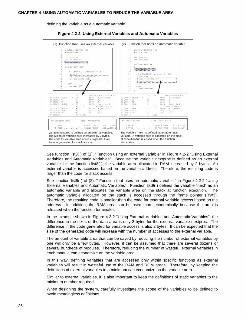
Figure 4.2-2 Using External Variables and Automatic Variables
See function list8( ) of (1), "Function using an external variable" in Figure 4.2-2 "Using ExternalVariables and Automatic Variables". Because the variable nextproc is defined as an externalvariable for the function list8( ), the variable area allocated in RAM increased by 2 bytes. Anexternal variable is accessed based on the variable address. Therefore, the resulting code islarger than the code for stack access.
See function list9( ) of (2), " Function that uses an automatic variable," in Figure 4.2-2 "UsingExternal Variables and Automatic Variables". Function list9( ) defines the variable "next" as anautomatic variable and allocates the variable area on the stack at function execution. Theautomatic variable allocated on the stack is accessed through the frame pointer (RW3).Therefore, the resulting code is smaller than the code for external variable access based on theaddress. In addition, the RAM area can be used more economically because the area isreleased when the function terminates.
In the example shown in Figure 4.2-2 "Using External Variables and Automatic Variables", thedifference in the sizes of the data area is only 2 bytes for the external variable nextproc. Thedifference in the code generated for variable access is also 2 bytes. It can be expected that thesize of the generated code will increase with the number of accesses to the external variable.
The amount of variable area that can be saved by reducing the number of external variables byone will only be a few bytes. However, it can be assumed that there are several dozens orseveral hundreds of modules. Therefore, reducing the number of wasteful external variables ineach module can economize on the variable area.
In this way, defining variables that are accessed only within specific functions as externalvariables will result in wasteful use of the RAM and ROM areas. Therefore, by keeping thedefinitions of external variables to a minimum can economize on the variable area.
Similar to external variables, it is also important to keep the definitions of static variables to theminimum number required.
When designing the system, carefully investigate the scope of the variables to be defined toavoid meaningless definitions.
(1) Function that uses an external variable (2) Function that uses an automatic variable
Variable nextproc is defined as an external variable.The allocated variable area increased by 2 bytes.The code for variable area access is greater thanthe one generated for stack access.
The variable "next" is defined as an automatic variable. A variable area is allocated on the stack at executionand released when the function terminates.
1 #define MAXPROC 100
2 #define ERR 1
3
4 int procno;
5 int currproc;
6 int nextproc;
7
8 int list8(void)
9 {
10 if ((MAXPROC - procno) >= 0){
11 procno++;
12 nextproc = currproc + 1;
13 return(nextproc);
14 }
15 else
16 return(ERR);
17 }
1 #define MAXPROC 100
2 #define ERR 1
3
4 int procno;
5 int currproc;
6
7 int list9(void)
8 {
9 int next;
10
11 if ((MAXPROC - procno) >= 0){
12 procno++;
13 next = currproc + 1;
14 return(next);
15 }
16 else
17 return(ERR);
18 }
NO SECTION-NAME SIZE ATTRIBUTES
0 DATA . . . . . . . . 000006 DATA REL ALIGN=2
1 CODE . . . . . . . . 000022 CODE REL ALIGN=1
NO SECTION-NAME SIZE ATTRIBUTES
0 DATA . . . . . . . . 000004 DATA REL ALIGN=2
1 CODE . . . . . . . . 000020 CODE REL ALIGN=1
35 ;;;; nextproc = currproc + 1;CO 000010 5A0000 R 36 MOVW A,_currproc
CO 000013 D1 37 MOVN A, #1CO 000014 28 38 ADDW A
CO 000015 5B0000 R 39 MOVW _nextproc, A
40 ;;;; return(nextproc);
CO 000018 5A0000 R 41 MOVW A,_nextproc
CO 00001B 6003 42 BRA L_24CO 00001D 6001 43 BRA L_25
CO 00001F 44 L_23:
30 ;;;; next = currproc + 1;CO 000010 5A0000 R 31 MOVW A,_currproc
CO 000013 D1 32 MOVN A, #1CO 000014 28 33 ADDW A
CO 000015 CBFE 34 MOVW @RW3+-2, A
35 ;;;; return(next);
CO 000017 BBFE 36 MOVW A, @RW3+-2
CO 000019 6003 37 BRA L_24CO 00001B 6001 38 BRA L_25
CO 00001D 39 L_23:
36
4.2 Using Automatic Variables
[Tip]
Softune C Analyzer:
The Softune C Analyzer lists the analysis results and the access status of external variables.This list can be used to determine from which function a defined external variable isaccessed. Variables that are only accessed by a defined module can also be identified fromthese results.
The Softune C Analyzer checks for function calls that use large amounts of the stack in theprogram system based on the amount of stack use calculated by the fcc907. The Softune CAnalyzer then visually displays the routes and amounts of usage. This information is usefulfor reducing the amount of stack usage.
37
CHAPTER 4 USING AUTOMATIC VARIABLES TO REDUCE THE VARIABLE AREA
38
CHAPTER 5 ACCESSING VARIABLES THAT USE BIT FIELDS
This chapter describes how to access variables that use bit fields.Using a bit field enables accessing each bit in a byte to be accessed.
5.1 "Boundary Alignment of fcc907"
5.2 "Bit Field Definitions and Boundary Alignment"
5.3 "Accessing I/O Areas Using Bit Fields and Unions"
39
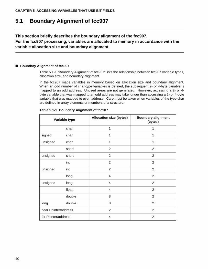
CHAPTER 5 ACCESSING VARIABLES THAT USE BIT FIELDS
5.1 Boundary Alignment of fcc907
This section briefly describes the boundary alignment of the fcc907.For the fcc907 processing, variables are allocated to memory in accordance with the variable allocation size and boundary alignment.
■ Boundary Alignment of fcc907
Table 5.1-1 "Boundary Alignment of fcc907" lists the relationship between fcc907 variable types,allocation size, and boundary alignment.
In the fcc907 maps variables in memory based on allocation size and boundary alignment.When an odd number of char-type variables is defined, the subsequent 2- or 4-byte variable ismapped to an odd address. Unused areas are not generated. However, accessing a 2- or 4-byte variable that was mapped to an odd address may take longer than accessing a 2- or 4-bytevariable that was mapped to even address. Care must be taken when variables of the type charare defined in array elements or members of a structure.
Table 5.1-1 Boundary Alignment of fcc907
Variable typeAllocation size (bytes) Boundary alignment
(bytes)
char 1 1
signed char 1 1
unsigned char 1 1
short 2 2
unsigned short 2 2
int 2 2
unsigned int 2 2
long 4 2
unsigned long 4 2
float 4 2
double 8 2
long double 8 2
near Pointer/address 2 2
for Pointer/address 4 2
40
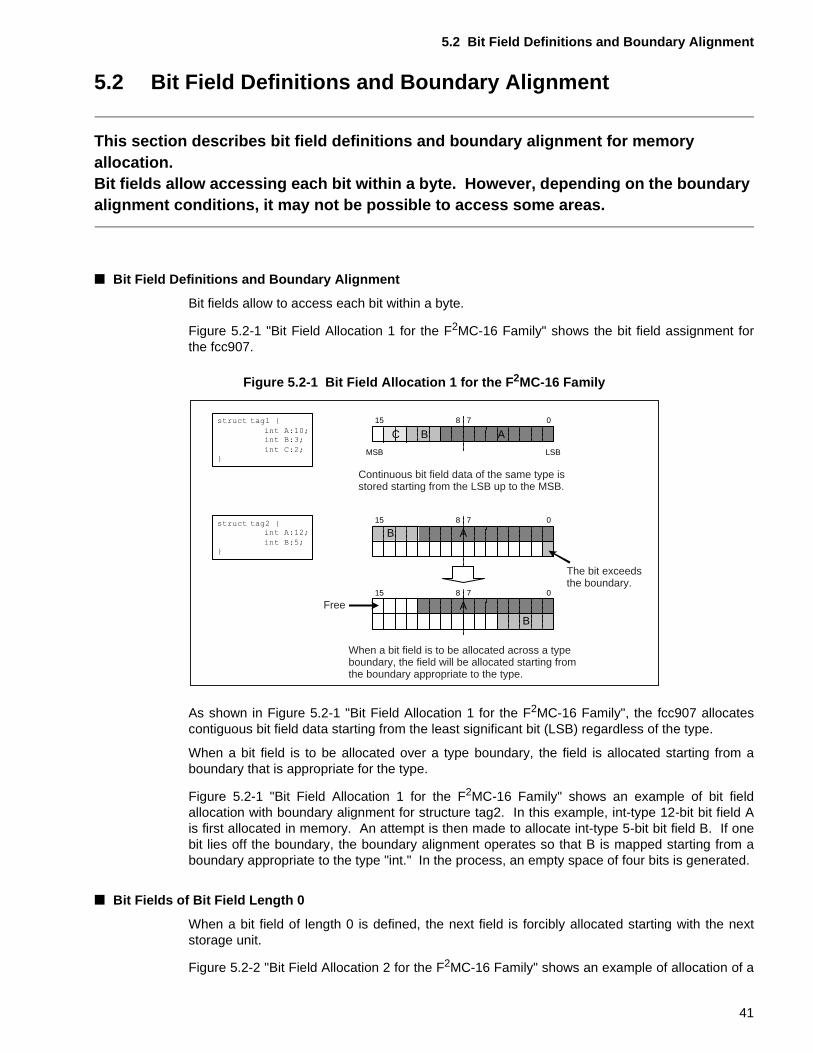
5.2 Bit Field Definitions and Boundary Alignment
5.2 Bit Field Definitions and Boundary Alignment
This section describes bit field definitions and boundary alignment for memory allocation.Bit fields allow accessing each bit within a byte. However, depending on the boundary alignment conditions, it may not be possible to access some areas.
■ Bit Field Definitions and Boundary Alignment
Bit fields allow to access each bit within a byte.
Figure 5.2-1 "Bit Field Allocation 1 for the F2MC-16 Family" shows the bit field assignment forthe fcc907.
Figure 5.2-1 Bit Field Allocation 1 for the F 2MC-16 Family
As shown in Figure 5.2-1 "Bit Field Allocation 1 for the F2MC-16 Family", the fcc907 allocatescontiguous bit field data starting from the least significant bit (LSB) regardless of the type.
When a bit field is to be allocated over a type boundary, the field is allocated starting from aboundary that is appropriate for the type.
Figure 5.2-1 "Bit Field Allocation 1 for the F2MC-16 Family" shows an example of bit fieldallocation with boundary alignment for structure tag2. In this example, int-type 12-bit bit field Ais first allocated in memory. An attempt is then made to allocate int-type 5-bit bit field B. If onebit lies off the boundary, the boundary alignment operates so that B is mapped starting from aboundary appropriate to the type "int." In the process, an empty space of four bits is generated.
■ Bit Fields of Bit Field Length 0
When a bit field of length 0 is defined, the next field is forcibly allocated starting with the nextstorage unit.
Figure 5.2-2 "Bit Field Allocation 2 for the F2MC-16 Family" shows an example of allocation of a
LSBMSB
B
0715 8
AB
0715 8
A
B0715 8
AC
Continuous bit field data of the same type is stored starting from the LSB up to the MSB.
When a bit field is to be allocated across a type boundary, the field will be allocated starting from the boundary appropriate to the type.
Free
The bit exceeds the boundary.
41
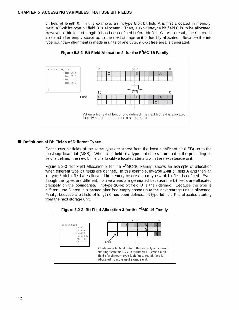
CHAPTER 5 ACCESSING VARIABLES THAT USE BIT FIELDS
bit field of length 0. In this example, an int-type 5-bit bit field A is first allocated in memory.Next, a 5-bit int-type bit field B is allocated. Then, a 6-bit int-type bit field C is to be allocated.However, a bit field of length 0 has been defined before bit field C. As a result, the C area isallocated after empty space up to the next storage unit is forcibly allocated. Because the int-type boundary alignment is made in units of one byte, a 6-bit free area is generated.
Figure 5.2-2 Bit Field Allocation 2 for the F 2MC-16 Family
■ Definitions of Bit Fields of Different Types
Continuous bit fields of the same type are stored from the least significant bit (LSB) up to themost significant bit (MSB). When a bit field of a type that differs from that of the preceding bitfield is defined, the new bit field is forcibly allocated starting with the next storage unit.
Figure 5.2-3 "Bit Field Allocation 3 for the F2MC-16 Family" shows an example of allocationwhen different type bit fields are defined. In this example, int-type 2-bit bit field A and then anint-type 6-bit bit field are allocated in memory before a char-type 4-bit bit field is defined. Eventhough the types are different, no free areas are generated because the bit fields are allocatedprecisely on the boundaries. Int-type 10-bit bit field D is then defined. Because the type isdifferent, the D area is allocated after free empty space up to the next storage unit is allocated.Finally, because a bit field of length 0 has been defined, int-type bit field F is allocated startingfrom the next storage unit.
Figure 5.2-3 Bit Field Allocation 3 for the F 2MC-16 Family
C
Free
When a bit field of length 0 is defined, the next bit field is allocatedforcibly starting from the next storage unit.
0715 8
0715 8
A
A
B
B
C
0715 8
A
D
BC
F
Free
Continuous bit field data of the same type is stored starting from the LSB up to the MSB. When a bit field of a different type is defined, the bit field is allocated from the next storage unit.
42
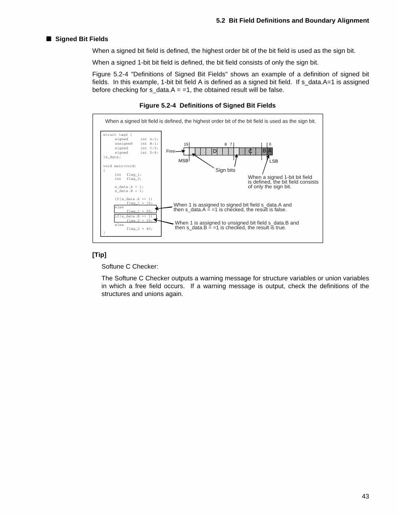
5.2 Bit Field Definitions and Boundary Alignment
■ Signed Bit Fields
When a signed bit field is defined, the highest order bit of the bit field is used as the sign bit.
When a signed 1-bit bit field is defined, the bit field consists of only the sign bit.
Figure 5.2-4 "Definitions of Signed Bit Fields" shows an example of a definition of signed bitfields. In this example, 1-bit bit field A is defined as a signed bit field. If s_data.A=1 is assignedbefore checking for s_data.A = =1, the obtained result will be false.
Figure 5.2-4 Definitions of Signed Bit Fields
[Tip]
Softune C Checker:
The Softune C Checker outputs a warning message for structure variables or union variablesin which a free field occurs. If a warning message is output, check the definitions of thestructures and unions again.
When a signed bit field is defined, the highest order bit of the bit field is used as the sign bit.
Sign bits
Free
When a signed 1-bit bit fieldis defined, the bit field consistsof only the sign bit.
When 1 is assigned to signed bit field s_data.A andthen s_data.A = =1 is checked, the result is false.
When 1 is assigned to unsigned bit field s_data.B andthen s_data.B = =1 is checked, the result is true.
LSBMSB
B0715 8
ACD
43
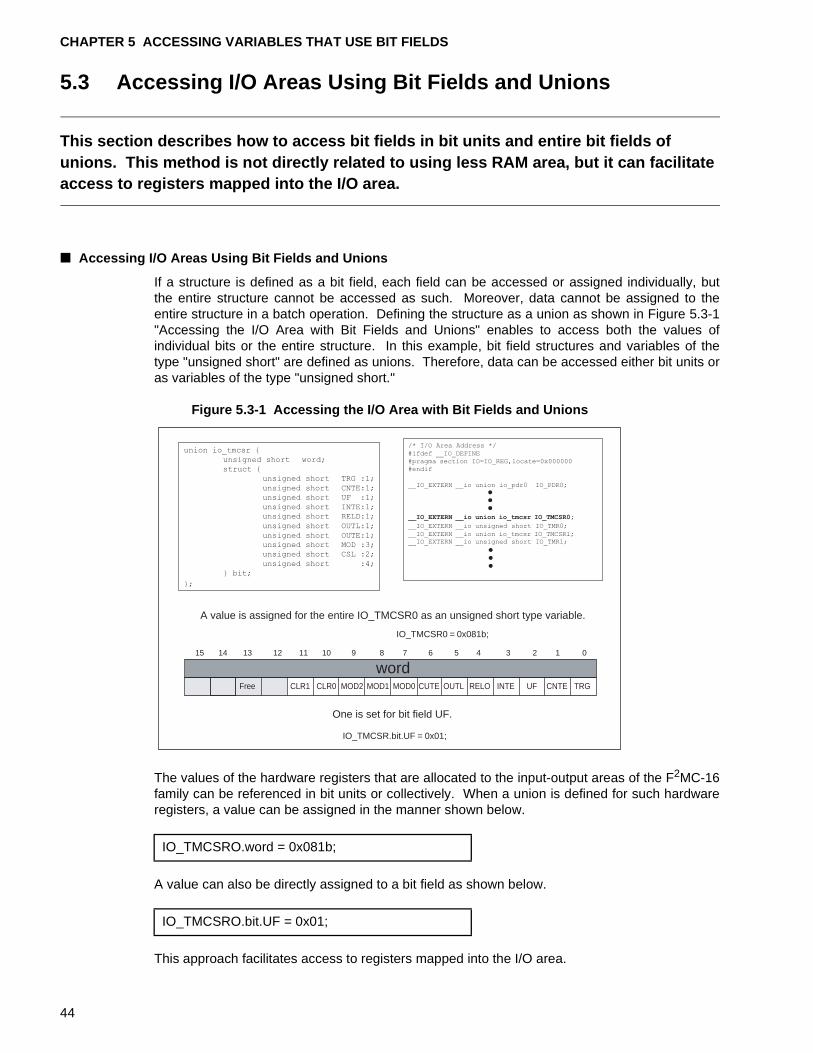
CHAPTER 5 ACCESSING VARIABLES THAT USE BIT FIELDS
5.3 Accessing I/O Areas Using Bit Fields and Unions
This section describes how to access bit fields in bit units and entire bit fields of unions. This method is not directly related to using less RAM area, but it can facilitate access to registers mapped into the I/O area.
■ Accessing I/O Areas Using Bit Fields and Unions
If a structure is defined as a bit field, each field can be accessed or assigned individually, butthe entire structure cannot be accessed as such. Moreover, data cannot be assigned to theentire structure in a batch operation. Defining the structure as a union as shown in Figure 5.3-1"Accessing the I/O Area with Bit Fields and Unions" enables to access both the values ofindividual bits or the entire structure. In this example, bit field structures and variables of thetype "unsigned short" are defined as unions. Therefore, data can be accessed either bit units oras variables of the type "unsigned short."
Figure 5.3-1 Accessing the I/O Area with Bit Fields and Unions
The values of the hardware registers that are allocated to the input-output areas of the F2MC-16family can be referenced in bit units or collectively. When a union is defined for such hardwareregisters, a value can be assigned in the manner shown below.
A value can also be directly assigned to a bit field as shown below.
This approach facilitates access to registers mapped into the I/O area.
IO_TMCSR0 = 0x081b;
IO_TMCSR.bit.UF = 0x01;
A value is assigned for the entire IO_TMCSR0 as an unsigned short type variable.
One is set for bit field UF.
91112131415 8
CLR1Free CLR0 MOD2 MOD1
7 6
CUTE
5
OUTL
4 3 2 1 0
RELO INTE UF CNTE TRG
10
MOD0
union io_tmcsr {
unsigned short word;struct {
unsigned short TRG :1;
unsigned short CNTE:1;unsigned short UF :1;unsigned short INTE:1;unsigned short RELD:1;
unsigned short OUTL:1;
unsigned short OUTE:1;unsigned short MOD :3;unsigned short CSL :2;
unsigned short :4;} bit;
/* I/O Area Address */#ifdef __IO_DEFINE#pragma section IO=IO_REG,locate=0x000000#endif
__IO_EXTERN __io union io_pdr0 IO_PDR0;
__IO_EXTERN __io union io_tmcsr IO_TMCSR0;
__IO_EXTERN __io unsigned short IO_TMR0;
__IO_EXTERN __io union io_tmcsr IO_TMCSR1;__IO_EXTERN __io unsigned short IO_TMR1;
word
};
IO_TMCSRO.word = 0x081b;
IO_TMCSRO.bit.UF = 0x01;
44
PART II USING STACK AREA EFFICIENTLY
Part II describes how to use stack areas efficiently in C programs.Part II first briefly describes the states of the stack areas at a function call. It then describes how to use the stack areas efficiently.
CHAPTER 6 "FUNCTION CALLS AND THE STACK"
CHAPTER 7 "REDUCING FUNCTION CALLS BY EXPANDING FUNCTIONS IN LINE"
CHAPTER 8 "REDUCING ARGUMENTS TO CONSERVE STACK AREA"
CHAPTER 9 "CONSERVING STACK AREA BY IMPROVEMENTS ON THE AREA FOR FUNCTION RETURN VALUES"
45

46
CHAPTER 6 FUNCTION CALLS AND THE STACK
Before describing how to use the stack area effectively, this chapter describes the areas that are allocated on the stack when a function is called.When a function is called, areas, such as the areas for arguments, are allocated on the stack as necessary.
6.1 "Areas Allocated on the Stack during Function Calls"
6.2 "Stack States When Function Calls Are Nested"
47
CHAPTER 6 FUNCTION CALLS AND THE STACK
6.1 Areas Allocated on the Stack during Function Calls
When a C program calls a function, a return address storage area and a previous frame pointer (RW3) save area are always allocated on the stack.
■ Areas Allocated on the Stack at Function Call
When a C program calls a function, the following areas are allocated on the stack as shown inFigure 6.1-1 "Areas Allocated on the Stack when a Function is Called":
❍ Actual argument and dummy argument areas
Used to hand over arguments during function calls.
• Actual argument: Argument specified by the calling function
• Dummy argument: Argument accessed by the called function
❍ Return address save area
Used to store the address for returning to the calling function.
This area is acquired or released by the calling function.
❍ Previous frame pointer save area
Used to save the value of the frame pointer (RW3 register) of the source calling the function.
❍ Local variable area
Used to store local variables or work variables.
This area is allocated at function entry, and released at function exit.
The size of this area depends on the number of the local variables to be stored. The greater thenumber of variables defined in the function, the larger the area allocated.
❍ Register save area
This area is used to save registers that must be preserved for the calling source.
This area is not allocated when no registers need to be saved.
❍ Return address value save area
This area is used to save the leading address of the area used to store the return value offunctions that return double type, long double type, structure type, or union type value.
48
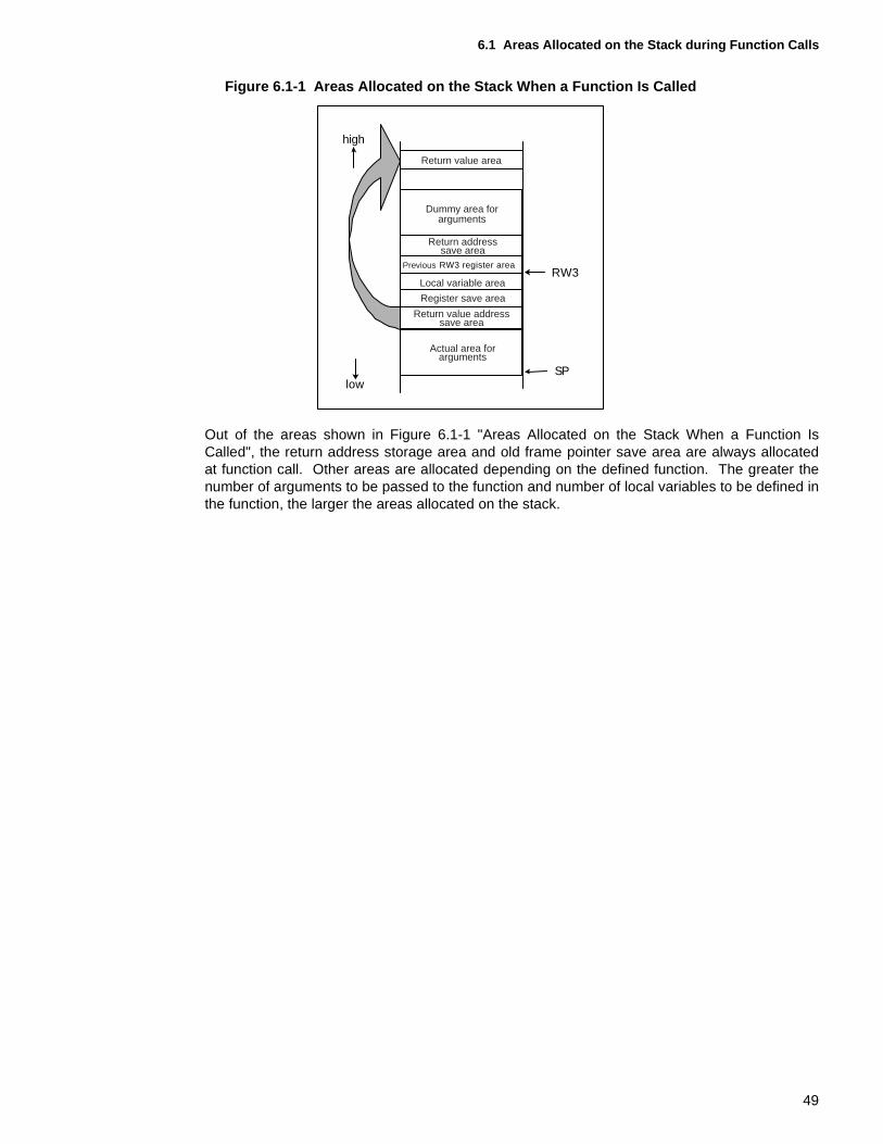
6.1 Areas Allocated on the Stack during Function Calls
Figure 6.1-1 Areas Allocated on the Stack When a Function Is Called
Out of the areas shown in Figure 6.1-1 "Areas Allocated on the Stack When a Function IsCalled", the return address storage area and old frame pointer save area are always allocatedat function call. Other areas are allocated depending on the defined function. The greater thenumber of arguments to be passed to the function and number of local variables to be defined inthe function, the larger the areas allocated on the stack.
Dummy area forarguments
Register save area
Local variable area
Return value addresssave area
RW3 register area
Return addresssave area
Actual area forarguments
RW3
SPlow
high
Return value area
Previous
49
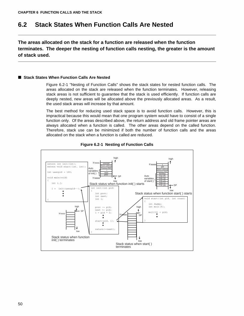
CHAPTER 6 FUNCTION CALLS AND THE STACK
6.2 Stack States When Function Calls Are Nested
The areas allocated on the stack for a function are released when the function terminates. The deeper the nesting of function calls nesting, the greater is the amount of stack used.
■ Stack States When Function Calls Are Nested
Figure 6.2-1 "Nesting of Function Calls" shows the stack states for nested function calls. Theareas allocated on the stack are released when the function terminates. However, releasingstack areas is not sufficient to guarantee that the stack is used efficiently. If function calls aredeeply nested, new areas will be allocated above the previously allocated areas. As a result,the used stack areas will increase by that amount.
The best method for reducing used stack space is to avoid function calls. However, this isimpractical because this would mean that one program system would have to consist of a singlefunction only. Of the areas described above, the return address and old frame pointer areas arealways allocated when a function is called. The other areas depend on the called function.Therefore, stack use can be minimized if both the number of function calls and the areasallocated on the stack when a function is called are reduced.
Figure 6.2-1 Nesting of Function Calls
low
low
userpid
high
SP
SP
high
high
SP
ipid
dummy[4]moji[3][2][1][0]
low
SP
high
low
inextprev
Previous RW3
Return address
Return address
Previous RW3
mojimojimojimoji
Autovariablesof init( )
Stack status when function start( ) starts
Stack status when start( )terminates
Stack status when functioninit( ) terminates
Stack status when function init( ) starts
Autovariablesof start( )
h'xxxx
h'xxxxh'aaaa
h'aaaa
h'aaaa
50
CHAPTER 7 REDUCING FUNCTION CALLS BY EXPANDING FUNCTIONS IN LINE
This chapter describes how to use inline expansion of functions to reduce function calls. Expanding functions in line reduces the amount of stack area required.
7.1 "Inline Expansion of Function"
7.2 "Conditions for Inline Expansion of Function"
51
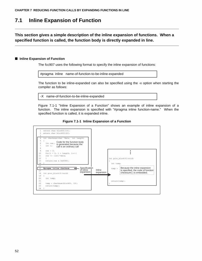
CHAPTER 7 REDUCING FUNCTION CALLS BY EXPANDING FUNCTIONS IN LINE
7.1 Inline Expansion of Function
This section gives a simple description of the inline expansion of functions. When a specified function is called, the function body is directly expanded in line.
■ Inline Expansion of Function
The fcc907 uses the following format to specify the inline expansion of functions:
The function to be inline-expanded can also be specified using the -x option when starting thecompiler as follows:
Figure 7.1-1 "Inline Expansion of a Function" shows an example of inline expansion of afunction. The inline expansion is specified with "#pragma inline function-name." When thespecified function is called, it is expanded inline.
Figure 7.1-1 Inline Expansion of a Function
#pragma inline name-of-function-to-be-inline-expanded
-X name-of-function-to-be-inline-expanded
Code for the function bodyis generated because thecall is an ordinary call
Inlineexpansion
Because the inline expansionis specified, the code of functionchecksum( ) is embedded.
Specificationof inlineexpansion
52
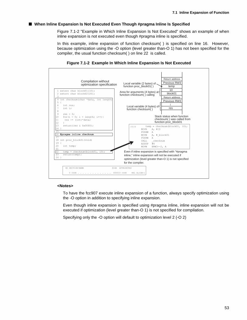
7.1 Inline Expansion of Function
■ When Inline Expansion Is Not Executed Even Though #pragma Inline Is Specified
Figure 7.1-2 "Example in Which Inline Expansion Is Not Executed" shows an example of wheninline expansion is not executed even though #pragma inline is specified.
In this example, inline expansion of function checksum( ) is specified on line 16. However,because optimization using the -O option (level greater than-O 1) has not been specified for thecompiler, the usual function checksum( ) on line 22 is called.
Figure 7.1-2 Example In Which Inline Expansion Is Not Executed
<Notes>
To have the fcc907 execute inline expansion of a function, always specify optimization usingthe -O option in addition to specifying inline expansion.
Even though inline expansion is specified using #pragma inline, inline expansion will not beexecuted if optimization (level greater than-O 1) is not specified for compilation.
Specifying only the -O option will default to optimization level 2 (-O 2)
10
ires
Local variable (2 bytes) offunction proc_block01( )
Area for arguments (4 bytes) atfunction checksum( ) calling
Local variable (4 bytes) offunction checksum( )
Return address
Return address
Previous RW3
Previous RW3
Stack status when functionchecksum( ) was called fromfunction proc_block01
Compilation withoutoptimization specification
Even if inline expansion is specified with "#pragmainline," inline expansion will not be executed ifoptimization (level greater than-O 1) is not specifiedfor the compiler.
temp
block01
;;;; temp = checksum(block01, 10);
MOVN A, #10
PUSHW A
MOVW A, #_block01
PUSHW A
CALL _checksum
ADDSP #4
MOVW @RW3+-2, A
NO SECTION-NAME SIZE ATTRIBUTES
0 CODE . . . . . . . . . . . . . . 000033 CODE REL ALIGN=1
1 extern char block01[10];
2 extern char block02[20];
3
4 int checksum(char *data, int length)
5 {
6 int res;
7 int i;
8
9 res = 0;10 for(i = 0; i < length; i++){
11 res += (int)*data;
12 }
13 return(res & 0x00ff);
14 }
15
16 #pragma inline checksum
1718 int proc_block01(void)
19 {
20 int temp;
21
22 temp = checksum(block01, 10);
23 return(temp);
24 }
53
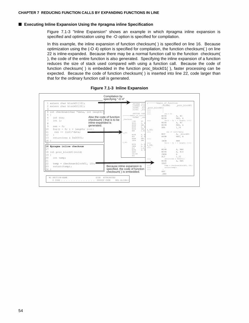
CHAPTER 7 REDUCING FUNCTION CALLS BY EXPANDING FUNCTIONS IN LINE
■ Executing Inline Expansion Using the #pragma inline Specification
Figure 7.1-3 "Inline Expansion" shows an example in which #pragma inline expansion isspecified and optimization using the -O option is specified for compilation.
In this example, the inline expansion of function checksum( ) is specified on line 16. Becauseoptimization using the (-O 4) option is specified for compilation, the function checksum( ) on line22 is inline-expanded. Because there may be a normal function call to the function checksum(), the code of the entire function is also generated. Specifying the inline expansion of a functionreduces the size of stack used compared with using a function call. Because the code offunction checksum( ) is embedded in the function proc_block01( ), faster processing can beexpected. Because the code of function checksum( ) is inserted into line 22, code larger thanthat for the ordinary function call is generated.
Figure 7.1-3 Inline Expansion
Compilation byspecifying "-O 4"
Also the code of functionchecksum( ) that is to beinline-expanded isgenerated.
.PROGRAM inline_func
.LIBRARY "lib907s.lib"
.GLOBAL _block02
.GLOBAL _block01
.SECTION CODE, CODE, ALIGN=1
;-------begin_of_function.GLOBAL _checksum
_checksum:
LINK #0
MOVN A, #0
MOVW RW5, A
MOVN A, #0
MOVW RW4, ABRA L_46
L_44:
MOVW A, @RW3+4
MOV A, @A
ADDW RW5, A
INCW RW4
L_46:
MOVW A, RW4
CMPW A, @RW3+6
BLT L_44
MOVW A, RW5
ZEXT
UNLINK
RET
;-------begin_of_function
.GLOBAL _proc_block01
_proc_block01:;;;; {
;;;; {
;;;; res = 0;
MOVN A, #0
MOVW RW5, A;;;; for(i = 0; i < length; i++){
MOVN A, #0
MOVW RW4, A
BRA L_54
L_52:;;;; res += (int)*data;
MOV A, _block01
ADDW RW5, A;;;; }
INCW RW4;;;; for(i = 0; i < length; i++){
L_54:;;;; }
MOVW A, RW4
MOVN A, #10
CMPW A
BLT L_52;;;; return(res & 0x00ff);
MOVW A, RW5
ZEXT;;;; temp = checksum(block01, 10);
;;;; return(temp);
;;;; }
RET
.END
NO SECTION-NAME SIZE ATTRIBUTES
0 CODE . . . . . . . . . . . . . . 00002F CODE REL ALIGN=1
1 extern char block01[10];
2 extern char block02[20];
3
4 int checksum(char *data, int length)
5 {
6 int res;
7 int i;
8
9 res = 0;
10 for(i = 0; i < length; i++){
11 res += (int)*data;
12 }
13 return(res & 0x00ff);
14 }
15
16 #pragma inline checksum
17
18 int proc_block01(void)
19 {
20 int temp;
21
22 temp = checksum(block01, 10);
23 return(temp);
24 }
Because inline expansion isspecified, the code of functionchecksum( ) is embedded.
54
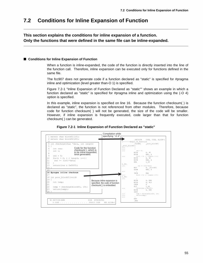
7.2 Conditions for Inline Expansion of Function
7.2 Conditions for Inline Expansion of Function
This section explains the conditions for inline expansion of a function.Only the functions that were defined in the same file can be inline-expanded.
■ Conditions for Inline Expansion of Function
When a function is inline-expanded, the code of the function is directly inserted into the line ofthe function call. Therefore, inline expansion can be executed only for functions defined in thesame file.
The fcc907 does not generate code if a function declared as "static" is specified for #pragmainline and optimization (level greater than-O 1) is specified.
Figure 7.2-1 "Inline Expansion of Function Declared as "static"" shows an example in which afunction declared as "static" is specified for #pragma inline and optimization using the (-O 4)option is specified.
In this example, inline expansion is specified on line 16. Because the function checksum( ) isdeclared as "static", the function is not referenced from other modules. Therefore, becausecode for function checksum( ) will not be generated, the size of the code will be smaller.However, if inline expansion is frequently executed, code larger than that for functionchecksum( ) can be generated.
Figure 7.2-1 Inline Expansion of Function Declared as "static"
Code for the function checksum( ), which is to be inline-expanded, isnot generated.
NO SECTION-NAME SIZE ATTRIBUTES
0 CODE . . . . . . . . . . . . . . 000015 CODE REL ALIGN=1
.SECTION CODE, CODE, ALIGN=1
;-------begin_of_function
.GLOBAL _proc_block01
_proc_block01:;;;; {
;;;; {
;;;; res = 0;
MOVN A, #0
MOVW RW5, A;;;; for(i = 0; i < length; i++){
MOVN A, #0
MOVW RW4, A
BRA L_46
L_44:;;;; res += (int)*data;
MOV A, _block01
ADDW RW5, A;;;; }
INCW RW4;;;; for(i = 0; i < length; i++){
L_46:;;;; }
MOVW A, RW4
MOVN A, #10
CMPW A
BLT L_44;;;; return(res & 0x00ff);
MOVW A, RW5
ZEXT;;;; temp = checksum(block01, 10);
;;;; return(temp);
;;;; }
RET
.END
1 extern char block01[10];
2 extern char block02[20];
3
4 int checksum(char *data, int length)
5 {
6 int res;
7 int i;
8
9 res = 0;
10 for(i = 0; i < length; i++){
11 res += (int)*data;
12 }
13 return(res & 0x00ff);
14 }
15
16 #pragma inline checksum
17
18 int proc_block01(void)
19 {
20 int temp;
21
22 temp = checksum(block01, 10);
23 return(temp);
24 }
Compilation whilespecifying "-O 4"
Because inline expansion isspecified, the code of functionchecksum( ) is embedded.
55
CHAPTER 7 REDUCING FUNCTION CALLS BY EXPANDING FUNCTIONS IN LINE
<Notes>
In the following cases, inline expansion is not executed even if specified:
• Optimization with the "-O option was not specified for compilation.
• Inline expansion was specified for a recursively called function.
• Inline expansion was specified for a function for which a structure or union was specified asargument.
• Inline expansion was specified for a file in which the setjmp function is called.
• Inline expansion was specified in a file containing the _ _asm statement.
• Arguments between functions do not match.
[Tip]
For the fcc907:
The number of lines of a function to be inline-expanded can be specified with the followingsize option for compilation.
When this option is specified, the functions that are specified with the size option are inline-expanded in compilation units. When the size option is not specified, functions consisting ofthirty lines or less are inline-expanded. Also in this case, the optimization (-O 1 or more)must be specified with the "-O" option.
Specifying the ADDSP option can reduce the overhead for function call processing andgenerate high-speed objects that are smaller than usual. However, this option willcollectively release the actual argument areas accumulated on the stack for function calls. Ifthis option is not specified, the amount of stack used will increase.
Softune C Analyzer:
The upper limit of the number of lines of a function to be inline-expanded can be specified.When analysis is executed with this option specified, the Softune C Analyzer will list thefunctions that are candidates for inline expansion after the analysis is completed. Thisfunction is helpful in determining the functions that will be expanded in line.
-xauto size-option
-K ADDSP-option
56
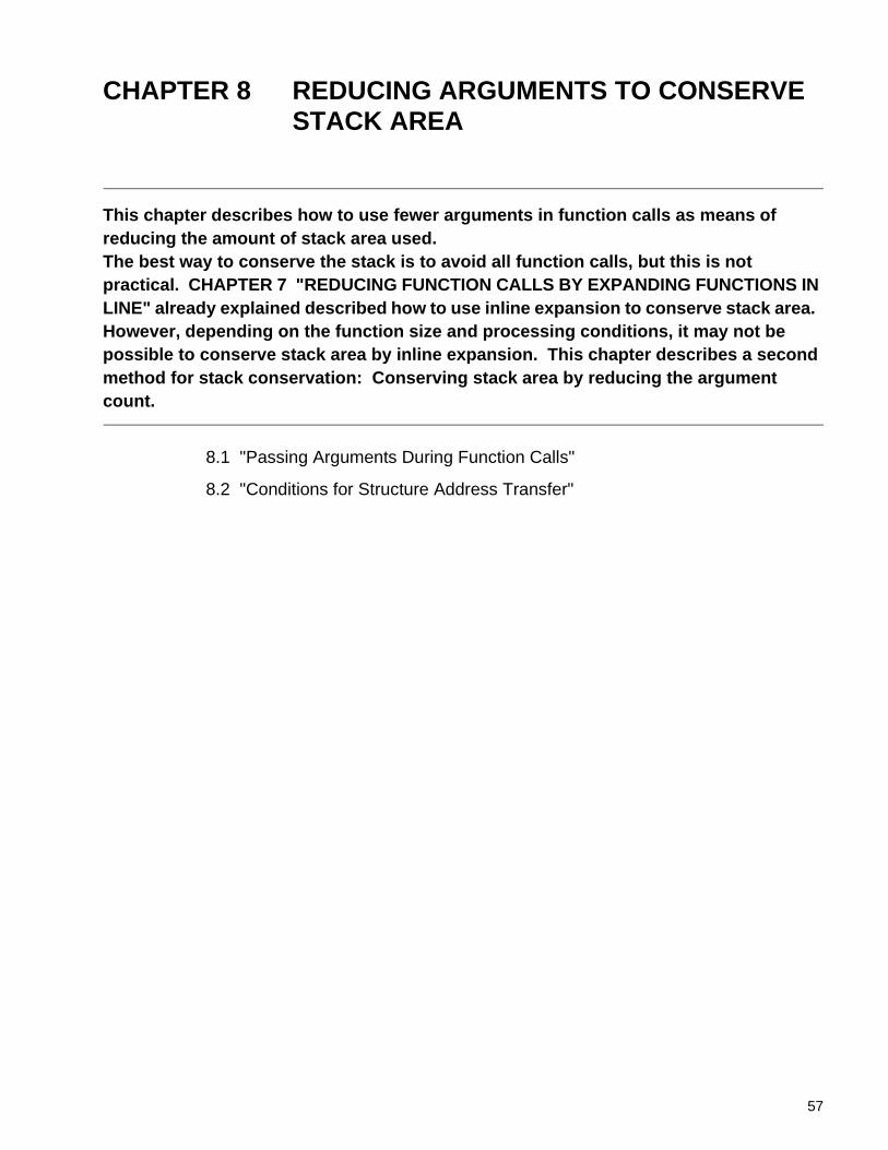
CHAPTER 8 REDUCING ARGUMENTS TO CONSERVE STACK AREA
This chapter describes how to use fewer arguments in function calls as means of reducing the amount of stack area used.The best way to conserve the stack is to avoid all function calls, but this is not practical. CHAPTER 7 "REDUCING FUNCTION CALLS BY EXPANDING FUNCTIONS IN LINE" already explained described how to use inline expansion to conserve stack area. However, depending on the function size and processing conditions, it may not be possible to conserve stack area by inline expansion. This chapter describes a second method for stack conservation: Conserving stack area by reducing the argument count.
8.1 "Passing Arguments During Function Calls"
8.2 "Conditions for Structure Address Transfer"
57
CHAPTER 8 REDUCING ARGUMENTS TO CONSERVE STACK AREA
8.1 Passing Arguments During Function Calls
This section describes how to pass arguments during function calls.When a function is called, the fcc907 stacks these arguments and passes them to the called function. Reducing the number of arguments for function calls conserves stack area. The following section describes how argumetns are passed at the example of a variable that is defined as a structure.
■ Argument Passing and Stack Usage Size
When a function is called, the fcc907 stacks these arguments and passes them to the calledfunction. The greater the number of arguments, the larger the stack area used. Reducing thenumber of arguments for function calls conserves stack area.
The following three methods for passing arguments are explained for variables defined as astructure:
• Normal Argument Passing
• Argument Structure Passing
• Address Passing of Structures
Figure 8.1-1 "Variable that is Defined as a Structure" shows an example for a variable that isdefined as a structure.
Figure 8.1-1 Variable That Is Defined as a Structure
data1data2
* msg "Hello !!"
Character string
Structure type frame declaration
58
8.1 Passing Arguments During Function Calls
8.1.1 Normal Argument Passing
During normal argument passing, arguments are stored on the stack sequentially before calling the function. Therefore, the greater the number of arguments, the larger the stack area used.
■ Normal Argument Passing
Figure 8.1-2 "Normal Argument Passing" shows an example for normal argument passing. Inthis example, a 6-byte area for saving three arguments is allocated on the stack. To copy thesearguments on the stack, a 9-byte code is required.
A 28-byte stack area is required for processing from calling function func_sub1( ) to itsexecution. (See (1), "Normal argument passing," in Figure 8.1-5 "Stack Usage Size Dependingon Argument Type during Function Calls".)
Figure 8.1-2 Normal Argument Passing
To pass three arguments, a 6-bytearea is allocated on the stack. To copy the arguments on thestack, a 9-byte code is required.
The arguments a and bcopied on the stack areaccessed.
The argument *moji that was copied on the stackis referenced.
#define FIRST 20#define SECOND 40
struct list{int data1;int data2;char *msg;
};
func_main(void){
int a;struct list code;
code.data1=FIRST;code.data2=SECOND;code.msg="Hello !!";
a=func_sub1(code.data1, code.data2, code.msg);}
int func_sub1(int a, int b, char *moji){
int total;char *c;char mojiretu[10];
total = a + b;c = mojiretu;while(*moji){
*c++ = *moji++;}return(total);
}
;;;; a=func_sub1(code.data1, code.data2, code.msg);MOVW A, @RW3+-2PUSHW AMOVW A, @RW3+-4PUSHW AMOVW A, @RW3+-6PUSHW ACALL _func_sub1ADDSP #6MOVW @RW3+-2, A
;;;; total = a + b;MOVW A, @RW3+4ADDW A, @RW3+6MOVW @RW3+-4, A
;;; while(*moji){L_27:;;;; while(*moji){
MOVW A, @RW3+8MOV A, DTB:@ABEQ L_26
;;;; *c++ = *moji++;MOVW A, @RW3+-2MOVW RW0, AMOVN A, #1ADDW AMOVW @RW3+-2, AMOVW A, @RW3+8MOVW RW1, AMOVN A, #1ADDW AMOVW @RW3+8, AMOV A, @RW1MOV @RW0, A
NO SECTION-NAME SIZE ATTRIBUTES
0 CONST . . . . . . . . . . . . . 000009 CONST REL ALIGN=2
1 CODE . . . . . . . . . . . . . . 000051 CODE REL ALIGN=1
59
CHAPTER 8 REDUCING ARGUMENTS TO CONSERVE STACK AREA
8.1.2 Argument Structure Passing
Argument structure passing can be performed with very simple C code. However, in this method of argument passing, all structure elements are copied on the stack and then passed to the function. Therefore, the larger the number of elements of the structure to be passed, the larger the stack area used.
■ Argument Structure Passing
Figure 8.1-3 "Argument Structure Passing" shows an example of argument structure passing.In this example, a 6-byte area for arguments is allocated on the stack in the same way asexplained in Section 8.1.1 "Normal Argument Passing". In addition, an 11-byte code is requiredfor copying the structure to the stack.
A 28-byte stack area is required for processing from calling function func_sub2( ) to itsexecution. (See (2), "Argument structure passing," in Figure 8.1-5 "Stack Usage SizeDepending on Argument Type during Function Calls".)
It is very easy when coding in C to specify a structure as an argument, but this method is notvery efficient in terms of the generated code and the required stack size.
Figure 8.1-3 Argument Structure Passing
To pass the argument structure, allthe structure codes are copied to thestack.A 6-byte area for saving the structurecodes is prepared on the stack.An 11-byte code is required for copying the structure to the stack.
NO SECTION-NAME SIZE ATTRIBUTES
0 CONST . . . . . . . . . . . . . 000009 CONST REL ALIGN=2
1 CODE . . . . . . . . . . . . . . 000057 CODE REL ALIGN=1
#define FIRST 20#define SECOND 40
struct list{int data1;int data2;char *msg;
};
func_main(void){
int a;struct list code;
code.data1=FIRST;code.data2=SECOND;code.msg="Hello !!";
a=func_sub2(code);}
int func_sub2(struct list str_data){
int total;char *c;char mojiretu[10];
total = str_data.data1 + str_data.data2;c = mojiretu;while(*str_data.msg){*c++ = *str_data.msg++;
}return(total);
}
;;;; total = str_data.data1 + str_data.data2;
MOVW A, @RW3+4
ADDW A, @RW3+6
MOVW @RW3+-4, A
;;;; c = mojiretu;
MOVEA A, @RW3+-14
MOVW @RW3+-2, A
;;;; while(*str_data.msg){
L_27:
;;;; while(*str_data.msg){
MOVW A, @RW3+8
MOV A, DTB:@ABEQ L_26
;;;; *c++ = *str_data.msg++;
MOVW A, @RW3+-2
MOVW RW0, A
MOVN A, #1
ADDW A
MOVW @RW3+-2, A
MOVW A, @RW3+8
MOVW RW1, A
MOVN A, #1
ADDW A
MOVW @RW3+8, A
MOV A, @RW1
MOV @RW0, A
;;;; a=func_sub2(code);
ADDSP #-6
MOVW A, SP
MOVEA A, @RW3+-8
MOVW RW0, #6
MOVSI SPB, SPB
CALL _func_sub2
ADDSP #6MOVW @RW3+-2, A
The structure elementsthat were copied to the stack are referenced.
60
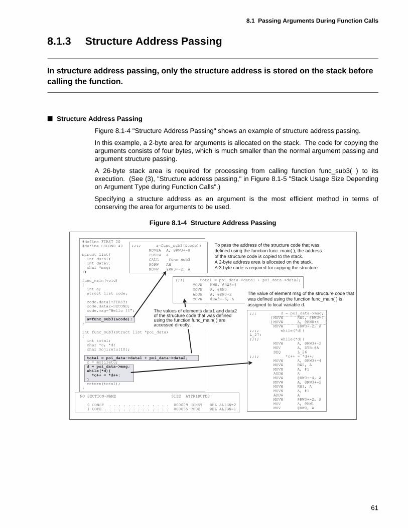
8.1 Passing Arguments During Function Calls
8.1.3 Structure Address Passing
In structure address passing, only the structure address is stored on the stack before calling the function.
■ Structure Address Passing
Figure 8.1-4 "Structure Address Passing" shows an example of structure address passing.
In this example, a 2-byte area for arguments is allocated on the stack. The code for copying thearguments consists of four bytes, which is much smaller than the normal argument passing andargument structure passing.
A 26-byte stack area is required for processing from calling function func_sub3( ) to itsexecution. (See (3), "Structure address passing," in Figure 8.1-5 "Stack Usage Size Dependingon Argument Type during Function Calls".)
Specifying a structure address as an argument is the most efficient method in terms ofconserving the area for arguments to be used.
Figure 8.1-4 Structure Address Passing
To pass the address of the structure code that was defined using the function func_main( ), the address of the structure code is copied to the stack. A 2-byte address area is allocated on the stack. A 3-byte code is required for copying the structure
#define FIRST 20#define SECOND 40
struct list{int data1;int data2;char *msg;
};
func_main(void){
int a;struct list code;
code.data1=FIRST;code.data2=SECOND;code.msg="Hello !!";
a=func_sub3(&code);}
int func_sub3(struct list *poi_data){
int total;char *c, *d;char mojiretu[10];
total = poi_data->data1 + poi_data->data2;c = mojiretu;d = poi_data->msg;while(*d){
*c++ = *d++;}return(total);
}
;;;; a=func_sub3(&code);
MOVEA A, @RW3+-8
PUSHW A
CALL _func_sub3
POPW AH
MOVW @RW3+-2, A
;;;; total = poi_data->data1 + poi_data->data2;
MOVW RW0, @RW3+4
MOVW A, @RW0
ADDW A, @RW0+2MOVW @RW3+-6, A
;;; d = poi_data->msg;MOVW RW0, @RW3+4MOVW A, @RW0+4MOVW @RW3+-2, A
;;;; while(*d){L_27:;;;; while(*d){
MOVW A, @RW3+-2MOV A, DTB:@ABEQ L_26
;;;; *c++ = *d++;MOVW A, @RW3+-4MOVW RW0, AMOVN A, #1ADDW AMOVW @RW3+-4, AMOVW A, @RW3+-2MOVW RW1, AMOVN A, #1ADDW AMOVW @RW3+-2, AMOV A, @RW1MOV @RW0, A
NO SECTION-NAME SIZE ATTRIBUTES
0 CONST . . . . . . . . . . . . . 000009 CONST REL ALIGN=21 CODE . . . . . . . . . . . . . . 000055 CODE REL ALIGN=1
The value of element msg of the structure code that was defined using the function func_main( ) is assigned to local variable d.
The values of elements data1 and data2 of the structure code that was defined using the function func_main( ) are accessed directly.
61
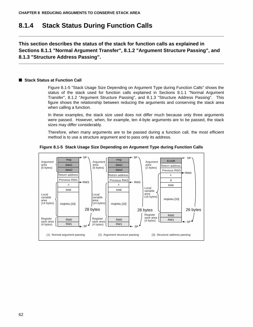
CHAPTER 8 REDUCING ARGUMENTS TO CONSERVE STACK AREA
8.1.4 Stack Status During Function Calls
This section describes the status of the stack for function calls as explained in Sections 8.1.1 "Normal Argument Transfer", 8.1.2 "Argument Structure Passing", and 8.1.3 "Structure Address Passing".
■ Stack Status at Function Call
Figure 8.1-5 "Stack Usage Size Depending on Argument Type during Function Calls" shows thestatus of the stack used for function calls explained in Sections 8.1.1 "Normal ArgumentTransfer", 8.1.2 "Argument Structure Passing", and 8.1.3 "Structure Address Passing". Thisfigure shows the relationship between reducing the arguments and conserving the stack areawhen calling a function.
In these examples, the stack size used does not differ much because only three argumentswere passed. However, when, for example, ten 4-byte arguments are to be passed, the stacksizes may differ considerably.
Therefore, when many arguments are to be passed during a function call, the most efficientmethod is to use a structure argument and to pass only its address.
Figure 8.1-5 Stack Usage Size Depending on Argument Type during Function Calls
msg
data1
data2
Previous RW3 Previous RW3
Previous RW3
c
total
mojiretu [10] mojiretu [10]
mojiretu [10]
msg
data1
data2
c
total
&code
c
d
total
RW0
RW1
RW0
RW1
RW0
RW1
SP SP SP
SP SP
SP
RW3 RW3
RW3
28 bytes 28 bytes 26 bytes
Argument area (6 bytes)
Argument area (6 bytes)
Argument area (2 bytes)
Local variable area (14 bytes)
Local variable area (14 bytes)
Local variable area (16 bytes)
Register save area (4 bytes)
Register save area (4 bytes)
Register save area (4 bytes)
Return address
Return address
Return address
(1) Normal argument passing (2) Argument structure passing (3) Structure address passing
62
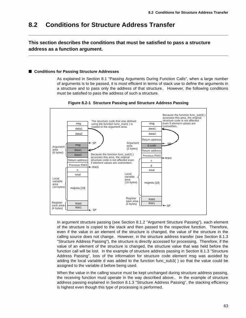
8.2 Conditions for Structure Address Transfer
8.2 Conditions for Structure Address Transfer
This section describes the conditions that must be satisfied to pass a structure address as a function argument.
■ Conditions for Passing Structure Addresses
As explained in Section 8.1 "Passing Arguments During Function Calls", when a large numberof arguments is to be passed, it is most efficient in terms of stack use to define the arguments ina structure and to pass only the address of that structure.. However, the following conditionsmust be satisfied to pass the address of such a structure.
Figure 8.2-1 Structure Passing and Structure Address Passing
In argument structure passing (see Section 8.1.2 "Argument Structure Passing"), each elementof the structure is copied to the stack and then passed to the respective function. Therefore,even if the value in an element of the structure is changed, the value of the structure in thecalling source does not change. However, in the structure address transfer (see Section 8.1.3"Structure Address Passing"), the structure is directly accessed for processing. Therefore, if thevalue of an element of the structure is changed, the structure value that was held before thefunction call will be lost. In the example of structure address passing in Section 8.1.3 "StructureAddress Passing", loss of the information for structure code element msg was avoided byadding the local variable d was added to the function func_sub3( ) so that the value could beassigned to the variable d before being used.
When the value in the calling source must be kept unchanged during structure address passing,the receiving function must operate in the way described above.. In the example of structureaddress passing explained in Section 8.1.3 "Structure Address Passing", the stacking efficiencyis highest even though this type of processing is performed.
msg
data1
data2
c
total
& code
c
d
total
RW0RW1
RW0RW1
SP SP
SP
SP
RW3
RW3
msg
data1
data2
msg
data1
data2
Previous RW3
Previous RW3
mojiretu [10]
mojiretu [10]
Argument area (6 bytes)
Argument area (2 bytes)
Local variable area (14 bytes)
Local variable area (16 bytes)
Register save area (4 bytes)
Register save area (4 bytes)
Return address
Return address
Return address
The structure code that was definedusing the function func_main( ) iscopied to the argument area.
Because the function func_sub3( )accesses this area, the originalstructure code is not affectedeven if element values are overwritten.
Because the function func_sub2( ) accesses this area, the original structure code is not affected even if element values are overwritten.
63
CHAPTER 8 REDUCING ARGUMENTS TO CONSERVE STACK AREA
[Tip]
Softune C Checker:
The Softune C Checker will output a warning if some arguments were not referenced at allby the called function. Also, if a structure or union was specified in an argument, a warningmessage is output to the effect that performance may be reduced. Examine the method ofargument passing considering the contents of these warning messages.
64
CHAPTER 9 CONSERVING STACK AREA BY IMPROVEMENTS ON THE AREA FOR FUNCTION RETURN VALUES
This chapter describes how to conserve stack area by improvements on the function return value area.As already described, the number of function calls and the number of arguments required for function calls can be reduced by using inline expansion. The size of stack used can also be reduced by improvements with respect to the return values of a function. This chapter describes this third method of stack conservation, reducing the size of the function return value area.
9.1 "Return Value of Functions"
9.2 "Functions Returning Structure-type Values and Stack Conservation"
9.3 "Functions Returning Union-type Values and Stack Conservation"
65
CHAPTER 9 CONSERVING STACK AREA BY IMPROVEMENTS ON THE AREA FOR FUNCTION RETURN VALUES
9.1 Return Value of Functions
This section describes the return values of functions.The type of a function is the type of the value returned when the function terminates. The type of this return value determines whether the return value is to be returned to the register or stack.
■ Return Value of Functions
The return value of functions have the same type as ordinary variables. When defining afunction, the type of the return value for the function must be specified. Table 9.1-1 "FunctionReturn Values and Return Value Interface" lists the relationship between function return valuesand the interface for return values.
Table 9.1-1 Function Return Values and Return Value Interface
Type of return value Allocated size (bytes) Return value interface
void --- ---
char 1 AL
signed char 1 AL
unsigned char 1 AL
short 2 AL
unsigned short 2 AL
int 2 AL
unsigned int 2 AL
long 4 A
unsigned long 4 A
float 4 A
double 8 On stack
long double 8 On stack
near Pointer/address 2 AL
for Pointer/address 2 A
66
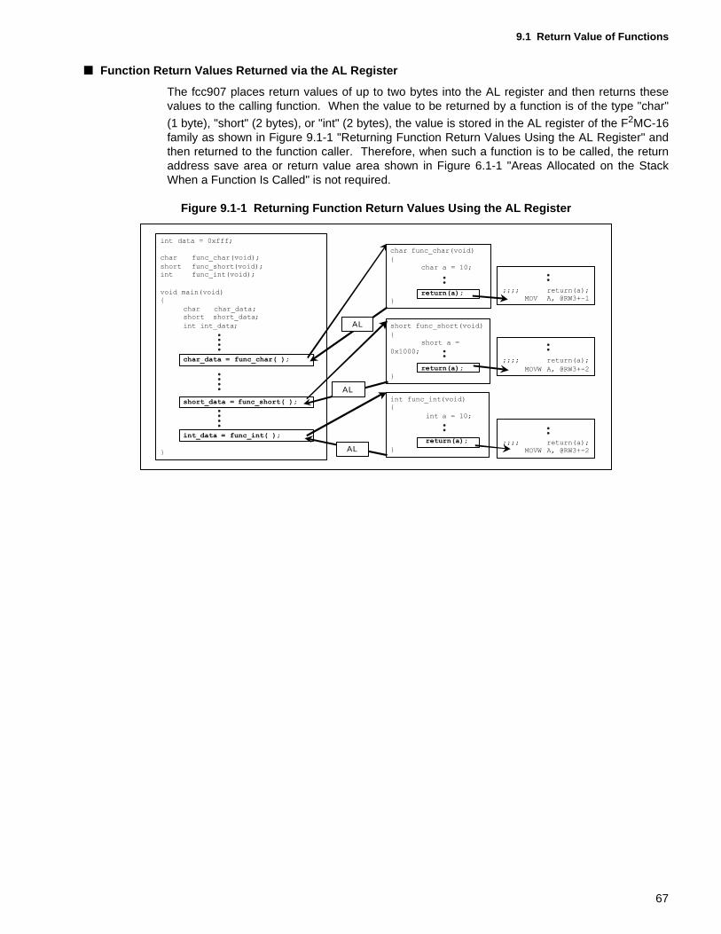
9.1 Return Value of Functions
■ Function Return Values Returned via the AL Register
The fcc907 places return values of up to two bytes into the AL register and then returns thesevalues to the calling function. When the value to be returned by a function is of the type "char"
(1 byte), "short" (2 bytes), or "int" (2 bytes), the value is stored in the AL register of the F2MC-16family as shown in Figure 9.1-1 "Returning Function Return Values Using the AL Register" andthen returned to the function caller. Therefore, when such a function is to be called, the returnaddress save area or return value area shown in Figure 6.1-1 "Areas Allocated on the StackWhen a Function Is Called" is not required.
Figure 9.1-1 Returning Function Return Values Using the AL Register
AL
AL
AL
67
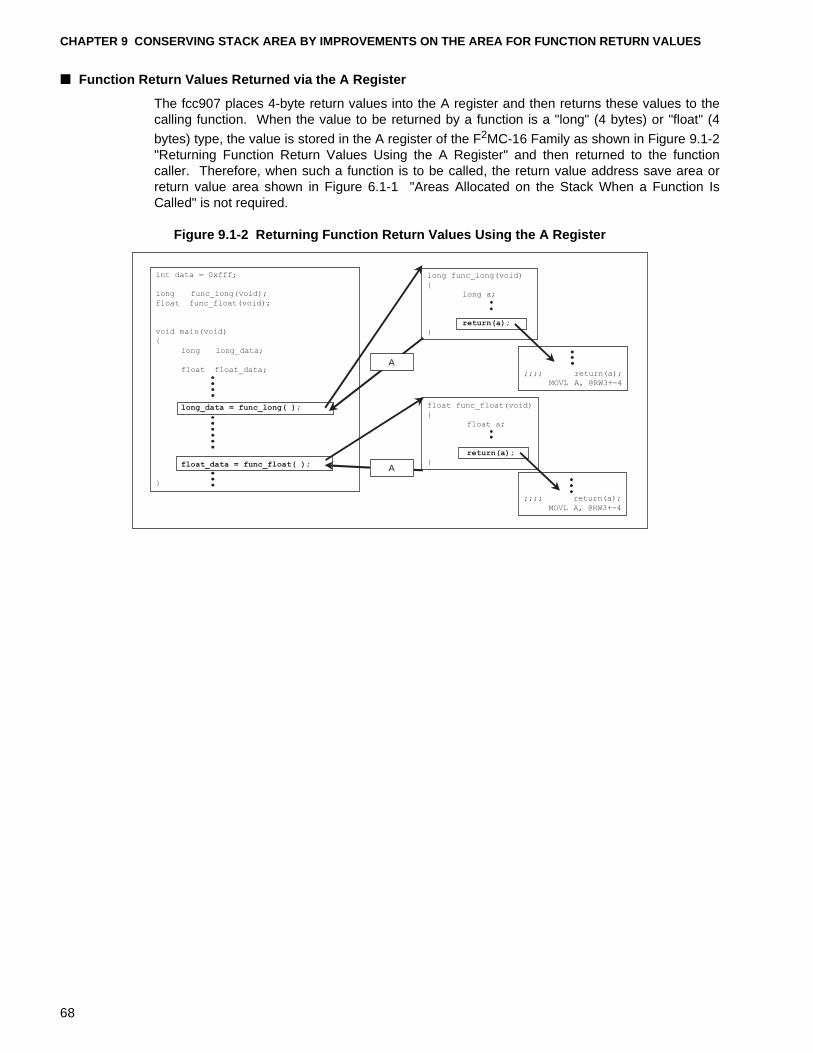
CHAPTER 9 CONSERVING STACK AREA BY IMPROVEMENTS ON THE AREA FOR FUNCTION RETURN VALUES
■ Function Return Values Returned via the A Register
The fcc907 places 4-byte return values into the A register and then returns these values to thecalling function. When the value to be returned by a function is a "long" (4 bytes) or "float" (4
bytes) type, the value is stored in the A register of the F2MC-16 Family as shown in Figure 9.1-2"Returning Function Return Values Using the A Register" and then returned to the functioncaller. Therefore, when such a function is to be called, the return value address save area orreturn value area shown in Figure 6.1-1 "Areas Allocated on the Stack When a Function IsCalled" is not required.
Figure 9.1-2 Returning Function Return Values Using the A Register
long func_long(void)
{
long a;
return(a);}
A
int data = 0xfff;
long func_long(void);
float func_float(void);
void main(void)
{
long long_data;
float float_data;
long_data = func_long( );
float_data = func_float( );
}
A
float func_float(void)
{
float a;
return(a);}
;;;; return(a);
MOVL A, @RW3+-4
;;;; return(a);
MOVL A, @RW3+-4
68
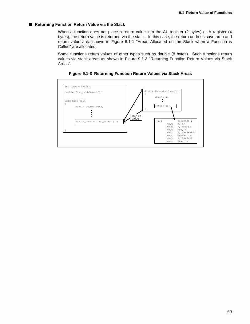
9.1 Return Value of Functions
■ Returning Function Return Value via the Stack
When a function does not place a return value into the AL register (2 bytes) or A register (4bytes), the return value is returned via the stack. In this case, the return address save area andreturn value area shown in Figure 6.1-1 "Areas Allocated on the Stack when a Function isCalled" are allocated.
Some functions return values of other types such as double (8 bytes). Such functions returnvalues via stack areas as shown in Figure 9.1-3 "Returning Function Return Values via StackAreas".
Figure 9.1-3 Returning Function Return Values via Stack Areas
MOVL @RW4, A
Returnvalue
69
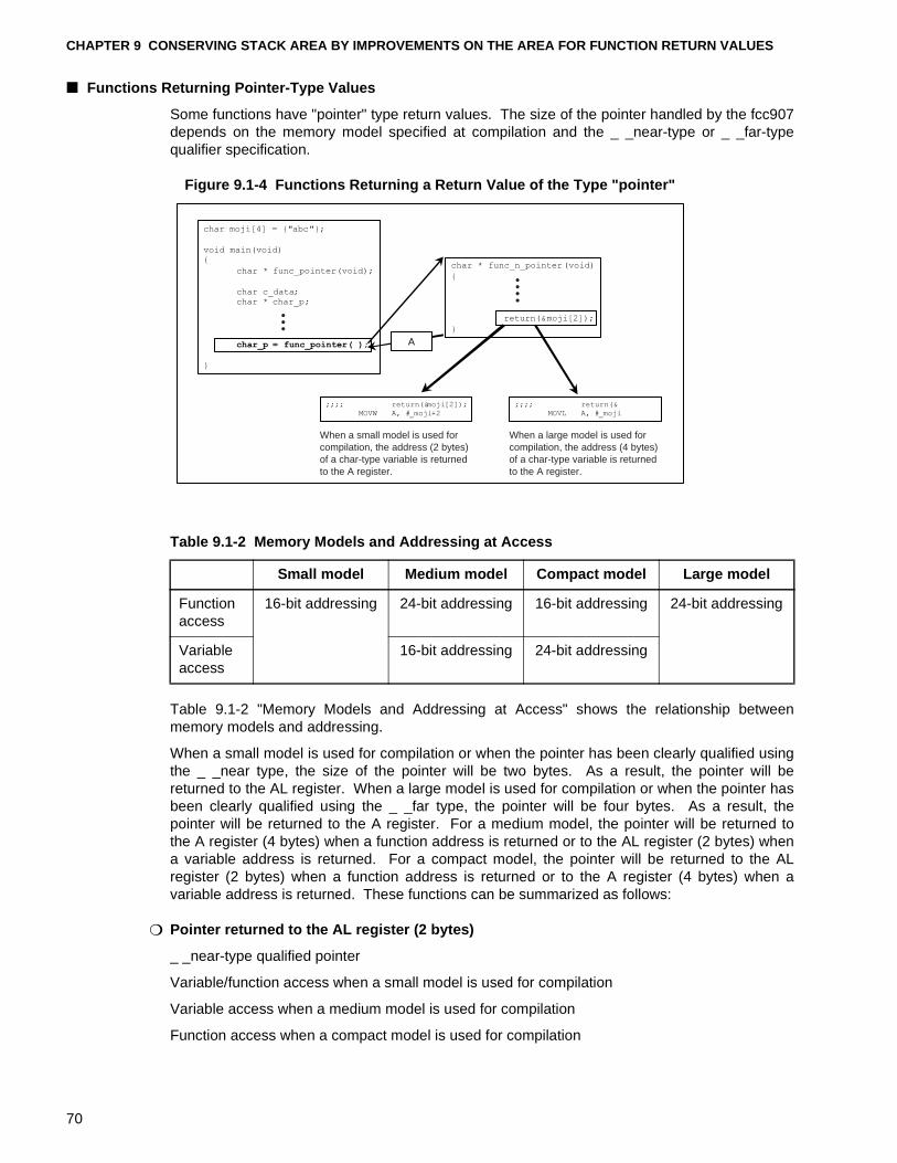
CHAPTER 9 CONSERVING STACK AREA BY IMPROVEMENTS ON THE AREA FOR FUNCTION RETURN VALUES
■ Functions Returning Pointer-Type Values
Some functions have "pointer" type return values. The size of the pointer handled by the fcc907depends on the memory model specified at compilation and the _ _near-type or _ _far-typequalifier specification.
Figure 9.1-4 Functions Returning a Return Value of the Type "pointer"
Table 9.1-2 "Memory Models and Addressing at Access" shows the relationship betweenmemory models and addressing.
When a small model is used for compilation or when the pointer has been clearly qualified usingthe _ _near type, the size of the pointer will be two bytes. As a result, the pointer will bereturned to the AL register. When a large model is used for compilation or when the pointer hasbeen clearly qualified using the _ _far type, the pointer will be four bytes. As a result, thepointer will be returned to the A register. For a medium model, the pointer will be returned tothe A register (4 bytes) when a function address is returned or to the AL register (2 bytes) whena variable address is returned. For a compact model, the pointer will be returned to the ALregister (2 bytes) when a function address is returned or to the A register (4 bytes) when avariable address is returned. These functions can be summarized as follows:
❍ Pointer returned to the AL register (2 bytes)
_ _near-type qualified pointer
Variable/function access when a small model is used for compilation
Variable access when a medium model is used for compilation
Function access when a compact model is used for compilation
A
When a small model is used for compilation, the address (2 bytes) of a char-type variable is returned to the A register.
When a large model is used for compilation, the address (4 bytes) of a char-type variable is returned to the A register.
Table 9.1-2 Memory Models and Addressing at Access
Small model Medium model Compact model Large model
Function access
16-bit addressing 24-bit addressing 16-bit addressing 24-bit addressing
Variable access
16-bit addressing 24-bit addressing
70
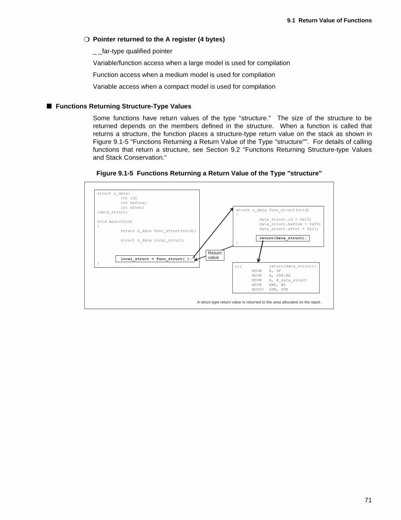
9.1 Return Value of Functions
❍ Pointer returned to the A register (4 bytes)
_ _far-type qualified pointer
Variable/function access when a large model is used for compilation
Function access when a medium model is used for compilation
Variable access when a compact model is used for compilation
■ Functions Returning Structure-Type Values
Some functions have return values of the type "structure." The size of the structure to bereturned depends on the members defined in the structure. When a function is called thatreturns a structure, the function places a structure-type return value on the stack as shown inFigure 9.1-5 "Functions Returning a Return Value of the Type "structure"". For details of callingfunctions that return a structure, see Section 9.2 "Functions Returning Structure-type Valuesand Stack Conservation."
Figure 9.1-5 Functions Returning a Return Value of the Type "structure"
A struct-type return value is returned to the area allocated on the stack.
struct s_data func_struct(void)
{
data_struct.id = 0x10;
data_struct.before = 0x09;
data_struct.after = 0x11;
return(data_struct);
}
struct s_data{
int id;
int before;
int after;
}data_struct;
void main(void)
{
struct s_data func_struct(void);
struct s_data local_struct;
local_struct = func_struct( );
};;; return(data_struct);
MOVW A, SP
MOVW A, DTB:@A
MOVW A, #_data_struct
MOVW RW0, #6
MOVSI SPB, DTB
Returnvalue
71
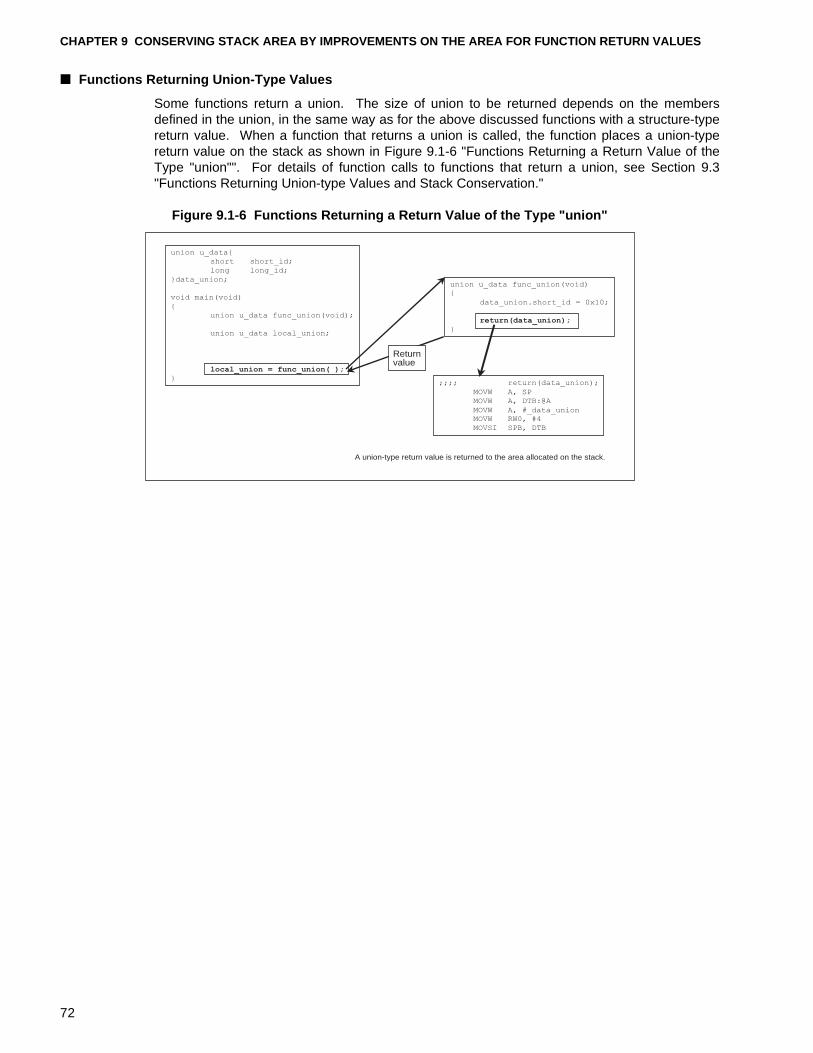
CHAPTER 9 CONSERVING STACK AREA BY IMPROVEMENTS ON THE AREA FOR FUNCTION RETURN VALUES
■ Functions Returning Union-Type Values
Some functions return a union. The size of union to be returned depends on the membersdefined in the union, in the same way as for the above discussed functions with a structure-typereturn value. When a function that returns a union is called, the function places a union-typereturn value on the stack as shown in Figure 9.1-6 "Functions Returning a Return Value of theType "union"". For details of function calls to functions that return a union, see Section 9.3"Functions Returning Union-type Values and Stack Conservation."
Figure 9.1-6 Functions Returning a Return Value of the Type "union"
A union-type return value is returned to the area allocated on the stack.
union u_data{
short short_id;
long long_id;
}data_union;
void main(void)
{
union u_data func_union(void);
union u_data local_union;
local_union = func_union( );
}
union u_data func_union(void){
data_union.short_id = 0x10;
return(data_union);
}
;;;; return(data_union);
MOVW A, SP
MOVW A, DTB:@A
MOVW A, #_data_unionMOVW RW0, #4
MOVSI SPB, DTB
Returnvalue
72
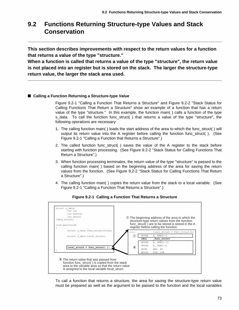
9.2 Functions Returning Structure-type Values and Stack Conservation
9.2 Functions Returning Structure-type Values and Stack Conservation
This section describes improvements with respect to the return values for a function that returns a value of the type "structure."When a function is called that returns a value of the type "structure", the return value is not placed into an register but is stored on the stack. The larger the structure-type return value, the larger the stack area used.
■ Calling a Function Returning a Structure-type Value
Figure 9.2-1 "Calling a Function That Returns a Structure" and Figure 9.2-2 "Stack Status forCalling Functions That Return a Structure" show an example of a function that has a returnvalue of the type "structure." In this example, the function main( ) calls a function of the types_data. To call the function func_struct( ) that returns a value of the type "structure", thefollowing operations are necessary:
1. The calling function main( ) loads the start address of the area to which the func_struct( ) willoutput its return value into the A register before calling the function func_struct( ). (SeeFigure 9.2-1 "Calling a Function that Returns a Structure".)
2. The called function func_struct( ) saves the value of the A register to the stack beforestarting with function processing. (See Figure 9.2-2 "Stack Status for Calling Functions ThatReturn a Structure".)
3. When function processing terminates, the return value of the type "structure" is passed to thecalling function main( ) based on the beginning address of the area for saving the returnvalues from the function. (See Figure 9.2-2 "Stack Status for Calling Functions That Returna Structure".)
4. The calling function main( ) copies the return value from the stack to a local variable. (SeeFigure 9.2-1 "Calling a Function That Returns a Structure".)
Figure 9.2-1 Calling a Function That Returns a Structure
To call a function that returns a structure, the area for saving the structure-type return valuemust be prepared as well as the argument to be passed to the function and the local variables
The return value that was passed fromfunction func_struct( ) is copied from the stackarea to the variable area so that the return valueis assigned to the local variable local_struct.
The beginning address of the area to which thestructure-type return values from the functionfunc_struct( ) are to be stored is stored in the Aregister before calling the function.
73
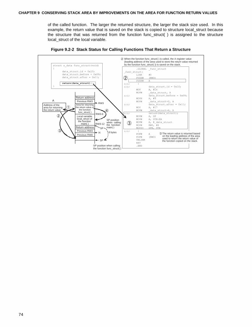
CHAPTER 9 CONSERVING STACK AREA BY IMPROVEMENTS ON THE AREA FOR FUNCTION RETURN VALUES
of the called function. The larger the returned structure, the larger the stack size used. In thisexample, the return value that is saved on the stack is copied to structure local_struct becausethe structure that was returned from the function func_struct( ) is assigned to the structurelocal_struct of the local variable.
Figure 9.2-2 Stack Status for Calling Functions That Return a Structure
ARW3
RW3-6
RW3-12
IX
SP
SP
8 bytes
When the function func_struct( ) is called, the A register value (leading address of the area used to store the return value returned by the function func_struct( )) is saved on the stack.
Address of the area for returning the return value
Return addressPrevious RW3
Area for returningthe return value of
the functionfunc_struct( )
Local variable local_struct of the function
main( )Return addressPrevious RW3
Previous RW0
SP position when callingthe functionmain( )
SP position when calling the function func_struct( )
The return value is returned based on the leading address of the area used to return the return value of the function copied on the stack.
struct s_data func_struct(void)
{
data_struct.id = 0x10;
data_struct.before = 0x09;
data_struct.after = 0x11;
return(data_struct);
}
.GLOBAL _func_struct
_func_struct:
LINK #0
PUSHW (RW0)
PUSHW A
;;;; {
;;;; data_struct.id = 0x10;
MOV A, #16
MOVW _data_struct, A
;;;; data_struct.before = 0x09;MOVN A, #9
MOVW _data_struct+2, A
;;;; data_struct.after = 0x11;
MOV A, #17
MOVW _data_struct+4, A
;;;; return(data_struct);
MOVW A, SP
MOVW A, DTB:@A
MOVW A, #_data_struct
MOVW RW0, #6MOVSI SPB, DTB
;;;; }
POPW A
POPW (RW0)UNLINK
RET
.END
74
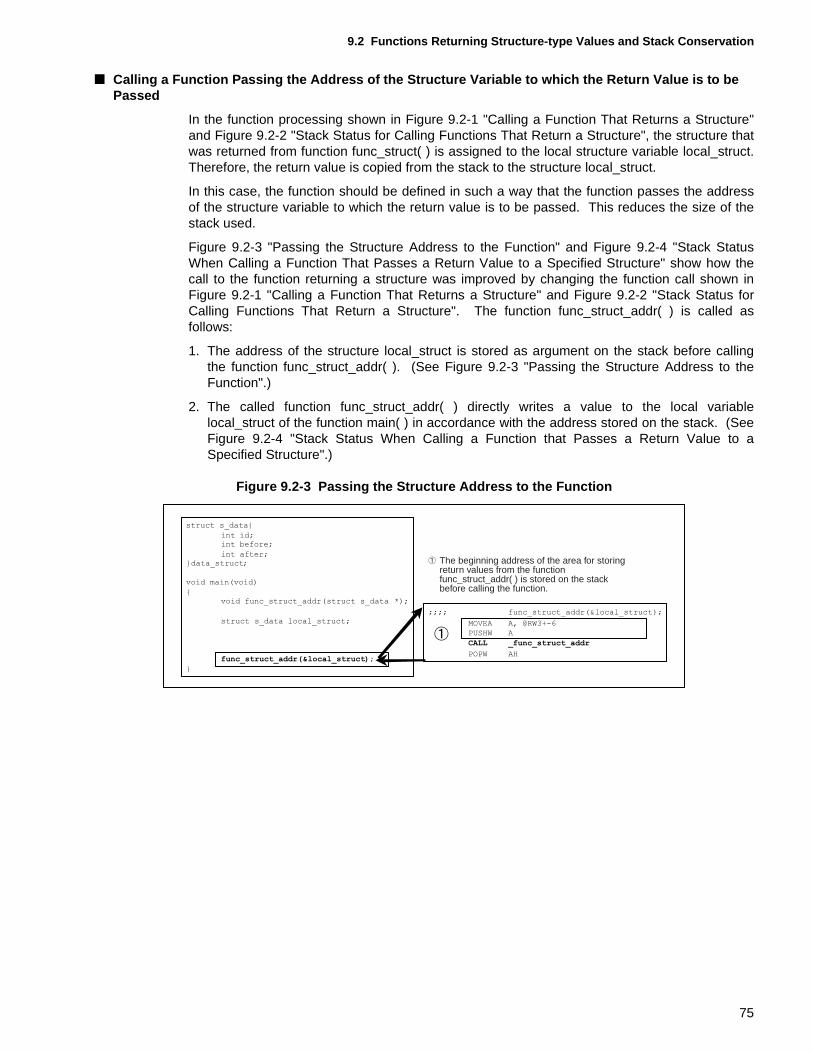
9.2 Functions Returning Structure-type Values and Stack Conservation
■ Calling a Function Passing the Address of the Structure Variable to which the Return Value is to be Passed
In the function processing shown in Figure 9.2-1 "Calling a Function That Returns a Structure"and Figure 9.2-2 "Stack Status for Calling Functions That Return a Structure", the structure thatwas returned from function func_struct( ) is assigned to the local structure variable local_struct.Therefore, the return value is copied from the stack to the structure local_struct.
In this case, the function should be defined in such a way that the function passes the addressof the structure variable to which the return value is to be passed. This reduces the size of thestack used.
Figure 9.2-3 "Passing the Structure Address to the Function" and Figure 9.2-4 "Stack StatusWhen Calling a Function That Passes a Return Value to a Specified Structure" show how thecall to the function returning a structure was improved by changing the function call shown inFigure 9.2-1 "Calling a Function That Returns a Structure" and Figure 9.2-2 "Stack Status forCalling Functions That Return a Structure". The function func_struct_addr( ) is called asfollows:
1. The address of the structure local_struct is stored as argument on the stack before callingthe function func_struct_addr( ). (See Figure 9.2-3 "Passing the Structure Address to theFunction".)
2. The called function func_struct_addr( ) directly writes a value to the local variablelocal_struct of the function main( ) in accordance with the address stored on the stack. (SeeFigure 9.2-4 "Stack Status When Calling a Function that Passes a Return Value to aSpecified Structure".)
Figure 9.2-3 Passing the Structure Address to the Function
The beginning address of the area for storingreturn values from the functionfunc_struct_addr( ) is stored on the stackbefore calling the function.
75
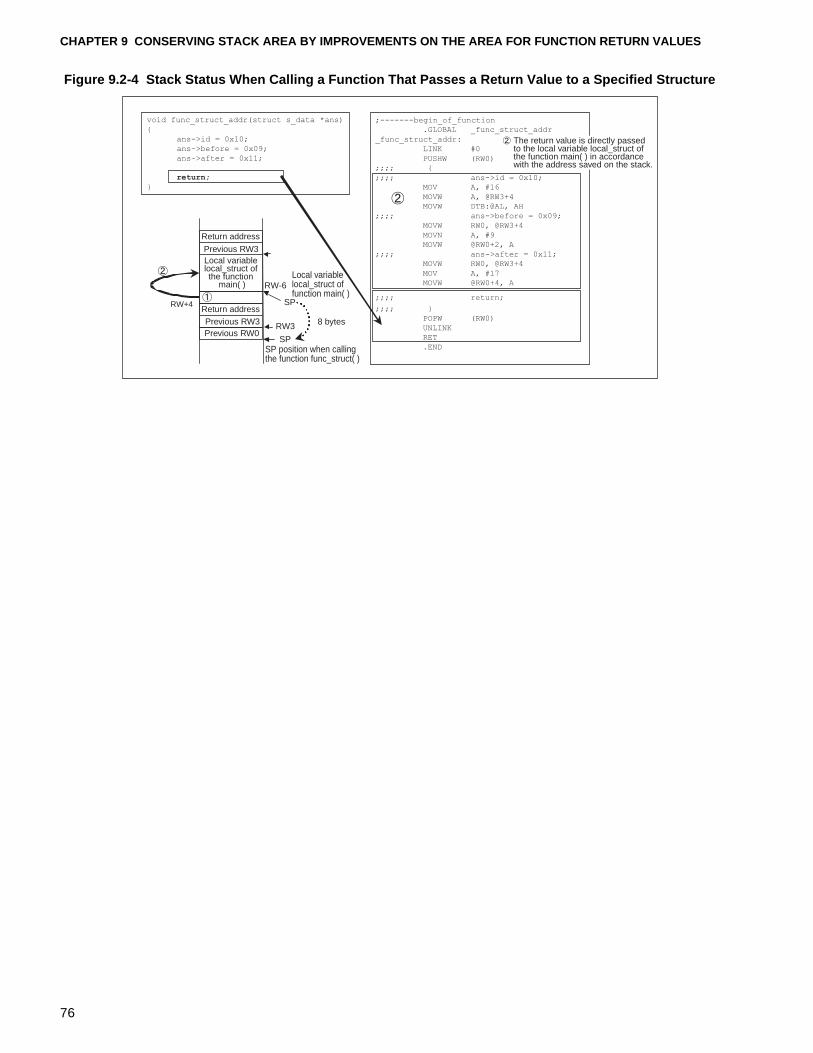
CHAPTER 9 CONSERVING STACK AREA BY IMPROVEMENTS ON THE AREA FOR FUNCTION RETURN VALUES
Figure 9.2-4 Stack Status When Calling a Function That Passes a Return Value to a Specified Structure
RW+4
RW-6
RW3
SP
SP
Local variable local_struct of the function
main( )
Return address
Return address
Previous RW3
Previous RW3Previous RW0
Local variablelocal_struct offunction main( )
8 bytes
SP position when calling the function func_struct( )
void func_struct_addr(struct s_data *ans)
{
ans->id = 0x10;
ans->before = 0x09;
ans->after = 0x11;
return;
}
;-------begin_of_function
.GLOBAL _func_struct_addr
_func_struct_addr:
LINK #0
PUSHW (RW0);;;; {
;;;; ans->id = 0x10;
MOV A, #16
MOVW A, @RW3+4
MOVW DTB:@AL, AH
;;;; ans->before = 0x09;
MOVW RW0, @RW3+4
MOVN A, #9
MOVW @RW0+2, A
;;;; ans->after = 0x11;
MOVW RW0, @RW3+4
MOV A, #17
MOVW @RW0+4, A
;;;; return;
;;;; }
POPW (RW0)
UNLINK
RET
.END
The return value is directly passedto the local variable local_struct ofthe function main( ) in accordancewith the address saved on the stack.
76
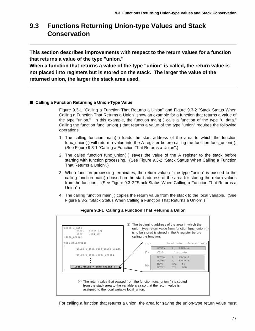
9.3 Functions Returning Union-type Values and Stack Conservation
9.3 Functions Returning Union-type Values and Stack Conservation
This section describes improvements with respect to the return values for a function that returns a value of the type "union."When a function that returns a value of the type "union" is called, the return value is not placed into registers but is stored on the stack. The larger the value of the returned union, the larger the stack area used.
■ Calling a Function Returning a Union-Type Value
Figure 9.3-1 "Calling a Function That Returns a Union" and Figure 9.3-2 "Stack Status WhenCalling a Function That Returns a Union" show an example for a function that returns a value ofthe type "union." In this example, the function main( ) calls a function of the type "u_data."Calling the function func_union( ) that returns a value of the type "union" requires the followingoperations:
1. The calling function main( ) loads the start address of the area to which the functionfunc_union( ) will return a value into the A register before calling the function func_union( ).(See Figure 9.3-1 "Calling a Function That Returns a Union".)
2. The called function func_union( ) saves the value of the A register to the stack beforestarting with function processing. (See Figure 9.3-2 "Stack Status When Calling a FunctionThat Returns a Union".)
3. When function processing terminates, the return value of the type "union" is passed to thecalling function main( ) based on the start address of the area for storing the return valuesfrom the function. (See Figure 9.3-2 "Stack Status When Calling a Function That Returns aUnion".)
4. The calling function main( ) copies the return value from the stack to the local variable. (SeeFigure 9.3-2 "Stack Status When Calling a Function That Returns a Union".)
Figure 9.3-1 Calling a Function That Returns a Union
For calling a function that returns a union, the area for saving the union-type return value must
The return value that passed from the function func_union ( ) is copiedfrom the stack area to the variable area so that the return value is assigned to the local variable local_union.
The beginning address of the area in which theunion_type return value from function func_union ( )is to be stored is stored in the A register beforecalling the function.
77
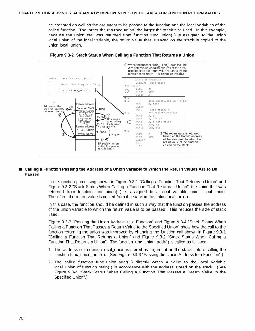
CHAPTER 9 CONSERVING STACK AREA BY IMPROVEMENTS ON THE AREA FOR FUNCTION RETURN VALUES
be prepared as well as the argument to be passed to the function and the local variables of thecalled function. The larger the returned union, the larger the stack size used. In this example,because the union that was returned from function func_union( ) is assigned to the unionlocal_union of the local variable, the return value that is saved on the stack is copied to theunion local_union.
Figure 9.3-2 Stack Status When Calling a Function That Returns a Union
■ Calling a Function Passing the Address of a Union Variable to Which the Return Values Are to Be Passed
In the function processing shown in Figure 9.3-1 "Calling a Function That Returns a Union" andFigure 9.3-2 "Stack Status When Calling a Function That Returns a Union", the union that wasreturned from function func_union( ) is assigned to a local variable union local_union.Therefore, the return value is copied from the stack to the union local_union.
In this case, the function should be defined in such a way that the function passes the addressof the union variable to which the return value is to be passed. This reduces the size of stackused.
Figure 9.3-3 "Passing the Union Address to a Function" and Figure 9.3-4 "Stack Status WhenCalling a Function That Passes a Return Value to the Specified Union" show how the call to thefunction returning the union was improved by changing the function call shown in Figure 9.3-1"Calling a Function That Returns a Union" and Figure 9.3-2 "Stack Status When Calling aFunction That Returns a Union". The function func_union_addr( ) is called as follows:
1. The address of the union local_union is stored as argument on the stack before calling thefunction func_union_addr( ). (See Figure 9.3-3 "Passing the Union Address to a Function".)
2. The called function func_union_addr( ) directly writes a value to the local variablelocal_union of function main( ) in accordance with the address stored on the stack. (SeeFigure 9.3-4 "Stack Status When Calling a Function That Passes a Return Value to theSpecified Union".)
A
RW3
RW3-4
RW3-8
RW3
SP
SP
When the function func_union( ) is called, the A register value (leading address of the area used to store the return value returned by the function func_union( )) is saved on the stack.
Address of thearea for returning the return value
Return address
Return address
Previous RW3
Previous RW3Previous RW0
Area for returningthe return valueof the functionfunc_union( )
Local variablelocal_union ofthe function
main( )
8 bytes
SP position when calling the function main( )
SP position when calling the function func_union( )
union u_data func_union(void)
{
data_union.long_id = 0xff;
return(data_union);
}
;-------begin_of_function
.GLOBAL _func_union
_func_union:
LINK #0
PUSHW (RW0)
PUSHW A
;;;; {
;;;; data_union.long_id = 0xff;
MOV A, #255
ZEXTW
MOVL _data_union, A
;;;; return(data_union);
MOVW A, SP
MOVW A, DTB:@A
MOVW A, #_data_union
MOVW RW0, #4MOVSI SPB, DTB
;;;; }
POPW A
POPW (RW0)
UNLINK
RET
.END
The return value is returned based on the leading addressof the area used to return the return value of the function copied on the stack.
78
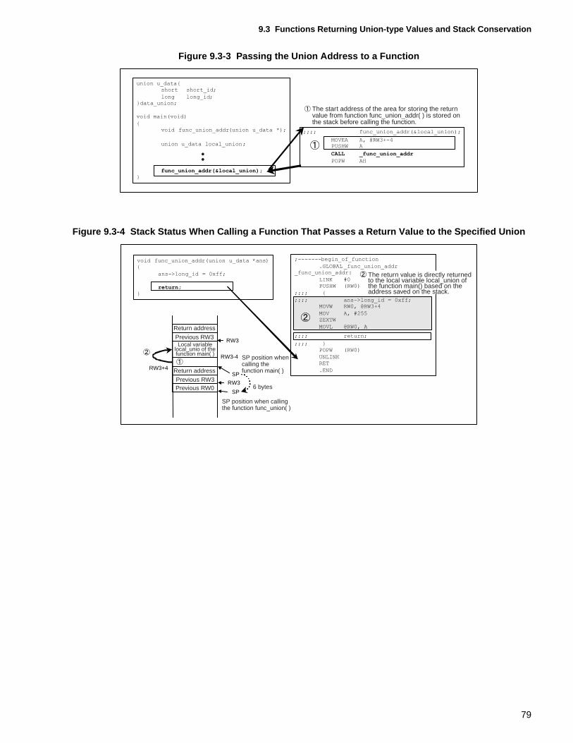
9.3 Functions Returning Union-type Values and Stack Conservation
Figure 9.3-3 Passing the Union Address to a Function
Figure 9.3-4 Stack Status When Calling a Function That Passes a Return Value to the Specified Union
The start address of the area for storing the returnvalue from function func_union_addr( ) is stored onthe stack before calling the function.
RW3
RW3-4
RW3
SP
SP
RW3+4
The return value is directly returned to the local variable local_union of the function main() based on the address saved on the stack.
Return address
Return address
Previous RW3
Previous RW3Previous RW0
Local variablelocal_unio of thefunction main( )
SP position when calling the function main( )
SP position when callingthe function func_union( )
6 bytes
79

CHAPTER 9 CONSERVING STACK AREA BY IMPROVEMENTS ON THE AREA FOR FUNCTION RETURN VALUES
80
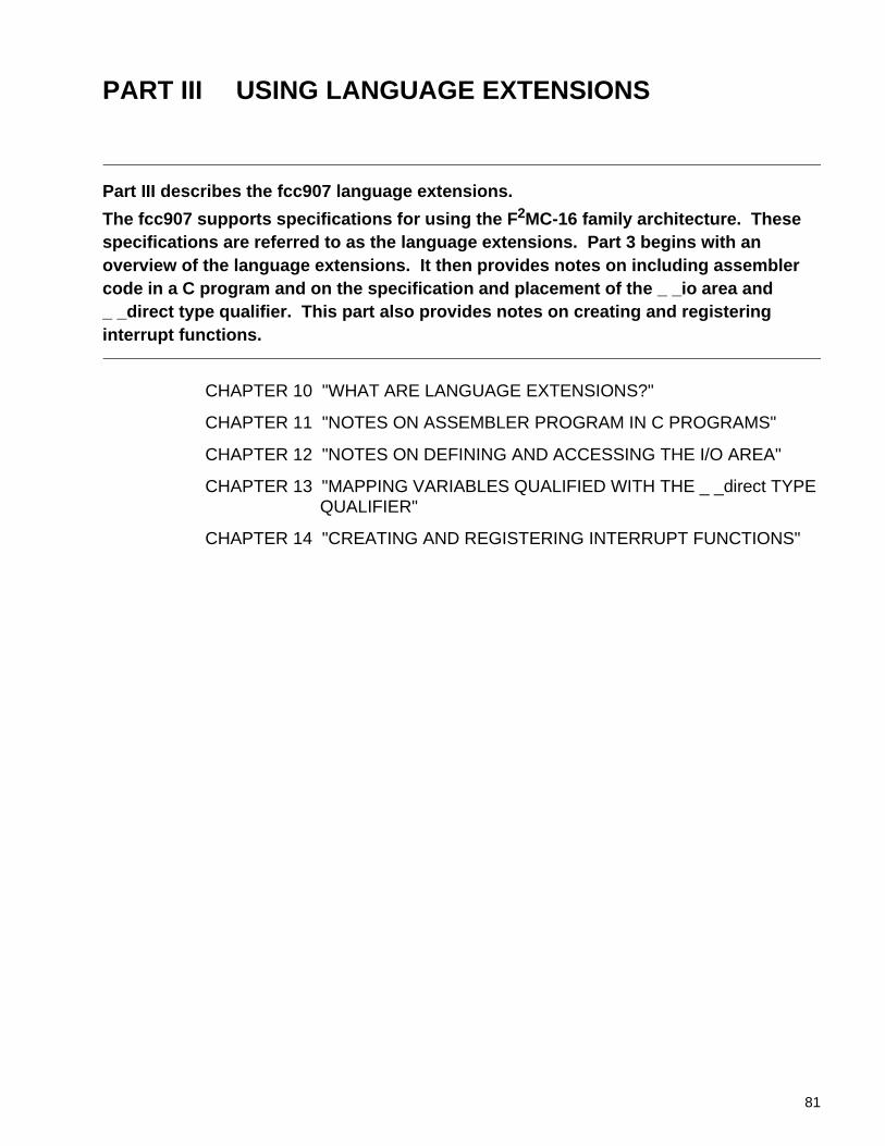
PART III USING LANGUAGE EXTENSIONS
Part III describes the fcc907 language extensions.
The fcc907 supports specifications for using the F 2MC-16 family architecture. These specifications are referred to as the language extensions. Part 3 begins with an overview of the language extensions. It then provides notes on including assembler code in a C program and on the specification and placement of the _ _io area and _ _direct type qualifier. This part also provides notes on creating and registering interrupt functions.
CHAPTER 10 "WHAT ARE LANGUAGE EXTENSIONS?"
CHAPTER 11 "NOTES ON ASSEMBLER PROGRAM IN C PROGRAMS"
CHAPTER 12 "NOTES ON DEFINING AND ACCESSING THE I/O AREA"
CHAPTER 13 "MAPPING VARIABLES QUALIFIED WITH THE _ _direct TYPE QUALIFIER"
CHAPTER 14 "CREATING AND REGISTERING INTERRUPT FUNCTIONS"
81

82
CHAPTER 10 WHAT ARE LANGUAGE EXTENSIONS?
The fcc907 provides the following functionality through language extensions:• Coding of Assembler instructions using an _ _asm statement• Extended type qualifiers• Extended functions using #pragma• Interrupt-related built-in functions• Other built-in functionsThis chapter describes these functions.
10.1 "Coding Assembler Instructions Using an _ _asm Statement"
10.2 "Extended Type Qualifiers"
10.3 "Extended Functions Using #pragma"
10.4 "Interrupt-Related Built-in Functions"
10.5 "Other Built-in Functions"
83
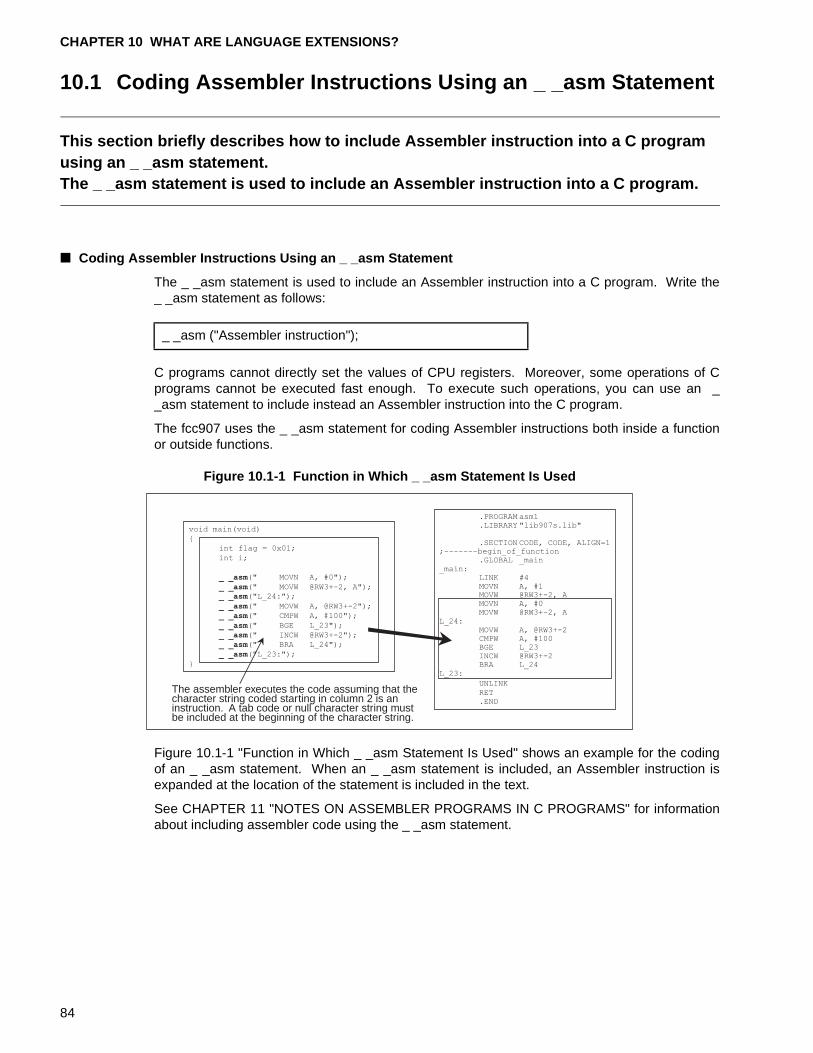
CHAPTER 10 WHAT ARE LANGUAGE EXTENSIONS?
10.1 Coding Assembler Instructions Using an _ _asm Statement
This section briefly describes how to include Assembler instruction into a C program using an _ _asm statement.The _ _asm statement is used to include an Assembler instruction into a C program.
■ Coding Assembler Instructions Using an _ _asm Statement
The _ _asm statement is used to include an Assembler instruction into a C program. Write the_ _asm statement as follows:
C programs cannot directly set the values of CPU registers. Moreover, some operations of Cprograms cannot be executed fast enough. To execute such operations, you can use an __asm statement to include instead an Assembler instruction into the C program.
The fcc907 uses the _ _asm statement for coding Assembler instructions both inside a functionor outside functions.
Figure 10.1-1 Function in Which _ _asm Statement Is Used
Figure 10.1-1 "Function in Which _ _asm Statement Is Used" shows an example for the codingof an _ _asm statement. When an _ _asm statement is included, an Assembler instruction isexpanded at the location of the statement is included in the text.
See CHAPTER 11 "NOTES ON ASSEMBLER PROGRAMS IN C PROGRAMS" for informationabout including assembler code using the _ _asm statement.
_ _asm ("Assembler instruction");
The assembler executes the code assuming that thecharacter string coded starting in column 2 is aninstruction. A tab code or null character string mustbe included at the beginning of the character string.
void main(void)
{
int flag = 0x01;
int i;
_ _asm(" MOVN A, #0");
_ _asm(" MOVW @RW3+-2, A");_ _asm("L_24:");
_ _asm(" MOVW A, @RW3+-2");
_ _asm(" CMPW A, #100");
_ _asm(" BGE L_23");
_ _asm(" INCW @RW3+-2");
_ _asm(" BRA L_24");
_ _asm("L_23:");
}
.PROGRAM asm1
.LIBRARY "lib907s.lib"
.SECTION CODE, CODE, ALIGN=1;-------begin_of_function
.GLOBAL _main_main:
LINK #4MOVN A, #1MOVW @RW3+-2, AMOVN A, #0MOVW @RW3+-2, A
L_24:MOVW A, @RW3+-2CMPW A, #100BGE L_23INCW @RW3+-2BRA L_24
L_23:
UNLINKRET.END
84
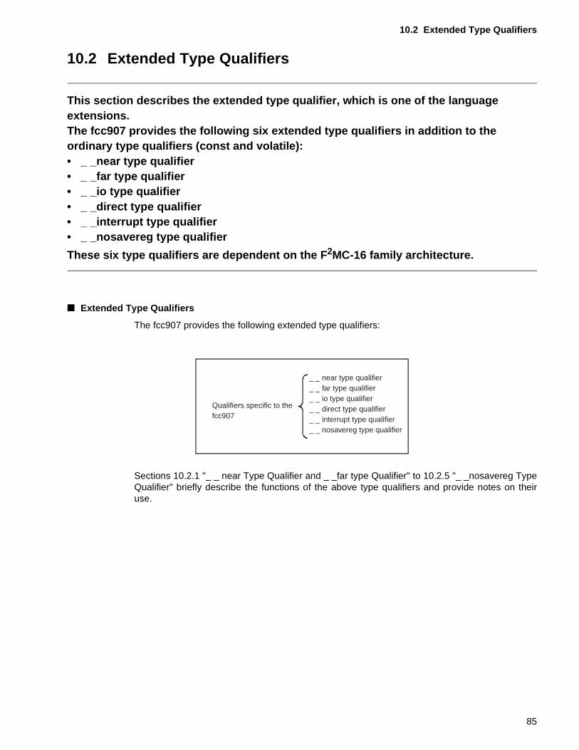
10.2 Extended Type Qualifiers
10.2 Extended Type Qualifiers
This section describes the extended type qualifier, which is one of the language extensions.The fcc907 provides the following six extended type qualifiers in addition to the ordinary type qualifiers (const and volatile):• _ _near type qualifier• _ _far type qualifier• _ _io type qualifier• _ _direct type qualifier• _ _interrupt type qualifier• _ _nosavereg type qualifier
These six type qualifiers are dependent on the F 2MC-16 family architecture.
■ Extended Type Qualifiers
The fcc907 provides the following extended type qualifiers:
Sections 10.2.1 "_ _ near Type Qualifier and _ _far type Qualifier" to 10.2.5 "_ _nosavereg TypeQualifier" briefly describe the functions of the above type qualifiers and provide notes on theiruse.
Qualifiers specific to the fcc907
_ _ near type qualifier_ _ far type qualifier_ _ io type qualifier_ _ direct type qualifier_ _ interrupt type qualifier_ _ nosavereg type qualifier
85
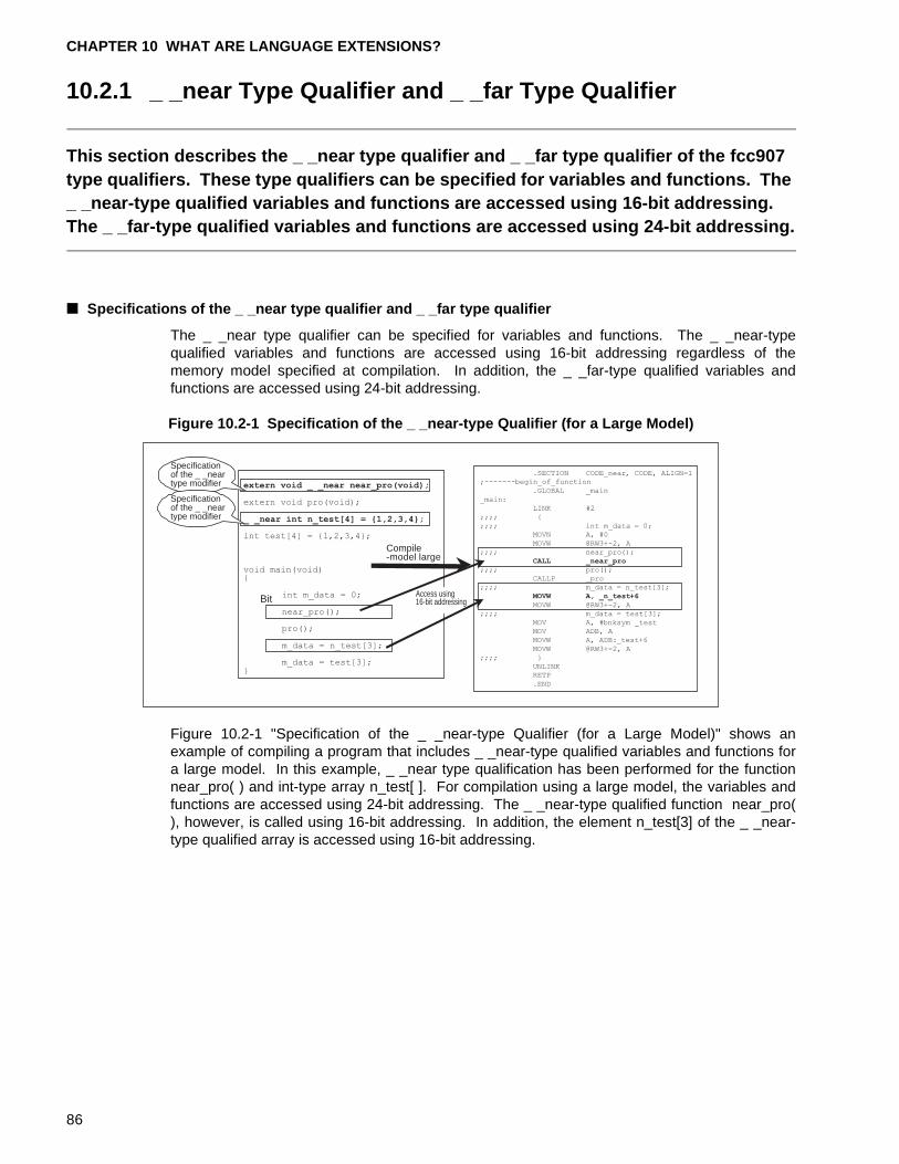
CHAPTER 10 WHAT ARE LANGUAGE EXTENSIONS?
10.2.1 _ _near Type Qualifier and _ _far Type Qualifier
This section describes the _ _near type qualifier and _ _far type qualifier of the fcc907 type qualifiers. These type qualifiers can be specified for variables and functions. The _ _near-type qualified variables and functions are accessed using 16-bit addressing. The _ _far-type qualified variables and functions are accessed using 24-bit addressing.
■ Specifications of the _ _near type qualifier and _ _far type qualifier
The _ _near type qualifier can be specified for variables and functions. The _ _near-typequalified variables and functions are accessed using 16-bit addressing regardless of thememory model specified at compilation. In addition, the _ _far-type qualified variables andfunctions are accessed using 24-bit addressing.
Figure 10.2-1 Specification of the _ _near-type Qualifier (for a Large Model)
Figure 10.2-1 "Specification of the _ _near-type Qualifier (for a Large Model)" shows anexample of compiling a program that includes _ _near-type qualified variables and functions fora large model. In this example, _ _near type qualification has been performed for the functionnear_pro( ) and int-type array n_test[ ]. For compilation using a large model, the variables andfunctions are accessed using 24-bit addressing. The _ _near-type qualified function near_pro(), however, is called using 16-bit addressing. In addition, the element n_test[3] of the _ _near-type qualified array is accessed using 16-bit addressing.
Bit
extern void _ _near near_pro(void);
extern void pro(void);
_ _near int n_test[4] = {1,2,3,4};
int test[4] = {1,2,3,4};
void main(void){
int m_data = 0;
near_pro();
pro();
m_data = n_test[3];
m_data = test[3];}
.SECTION CODE_near, CODE, ALIGN=1
;-------begin_of_function
.GLOBAL _main
_main:
LINK #2
;;;; {
;;;; int m_data = 0;
MOVN A, #0
MOVW @RW3+-2, A
;;;; near_pro();
CALL _near_pro
;;;; pro();
CALLP _pro
;;;; m_data = n_test[3];
MOVW A, _n_test+6
MOVW @RW3+-2, A
;;;; m_data = test[3];
MOV A, #bnksym _test
MOV ADB, A
MOVW A, ADB:_test+6
MOVW @RW3+-2, A
;;;; }
UNLINK
RETP
.END
Specification of the _ _near type modifier
Specificationof the _ _neartype modifier
Compile-model large
Access using 16-bit addressing
86
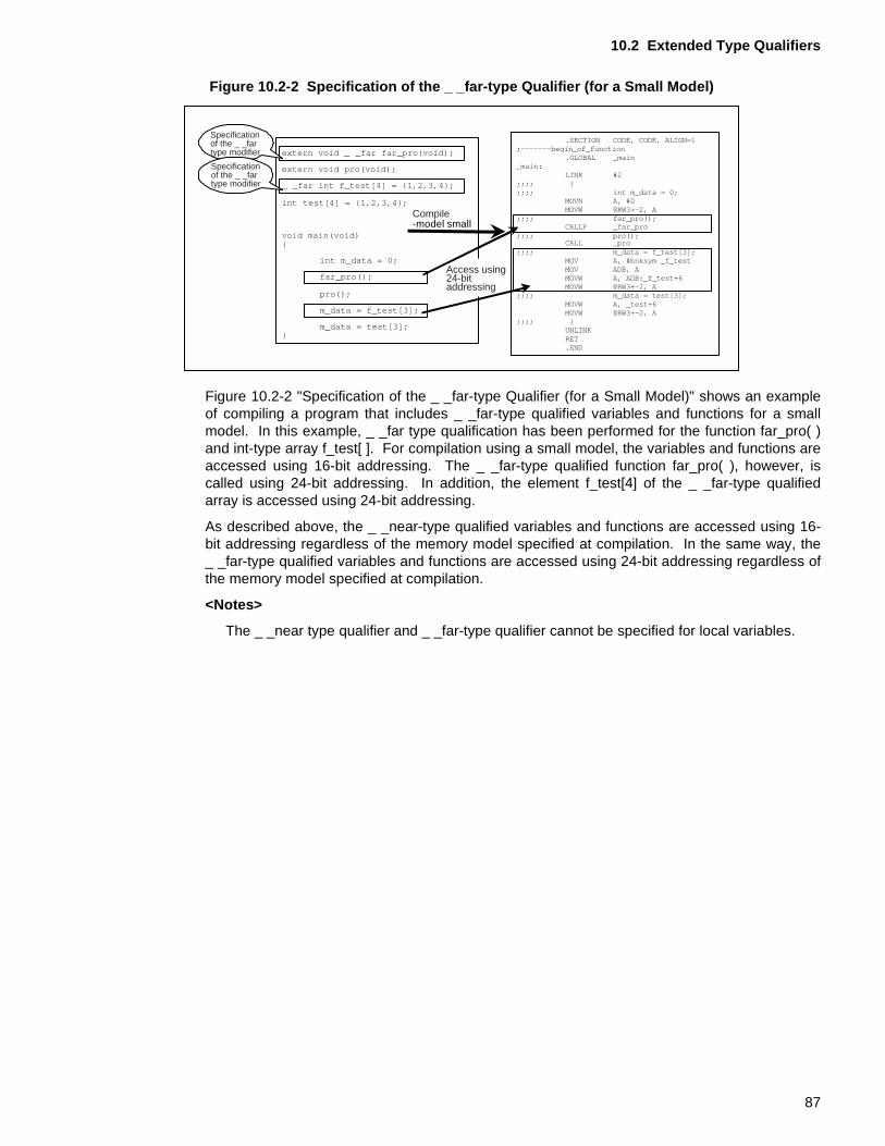
10.2 Extended Type Qualifiers
Figure 10.2-2 Specification of the _ _far-type Qualifier (for a Small Model)
Figure 10.2-2 "Specification of the _ _far-type Qualifier (for a Small Model)" shows an exampleof compiling a program that includes _ _far-type qualified variables and functions for a smallmodel. In this example, _ _far type qualification has been performed for the function far_pro( )and int-type array f_test[ ]. For compilation using a small model, the variables and functions areaccessed using 16-bit addressing. The _ _far-type qualified function far_pro( ), however, iscalled using 24-bit addressing. In addition, the element f_test[4] of the _ _far-type qualifiedarray is accessed using 24-bit addressing.
As described above, the _ _near-type qualified variables and functions are accessed using 16-bit addressing regardless of the memory model specified at compilation. In the same way, the_ _far-type qualified variables and functions are accessed using 24-bit addressing regardless ofthe memory model specified at compilation.
<Notes>
The _ _near type qualifier and _ _far-type qualifier cannot be specified for local variables.
extern void _ _far far_pro(void);
extern void pro(void);
_ _far int f_test[4] = {1,2,3,4};
int test[4] = {1,2,3,4};
void main(void){
int m_data = 0;
far_pro();
pro();
m_data = f_test[3];
m_data = test[3];}
.SECTION CODE, CODE, ALIGN=1;-------begin_of_function
.GLOBAL _main_main:
LINK #2;;;; {;;;; int m_data = 0;
MOVN A, #0MOVW @RW3+-2, A
;;;; far_pro();CALLP _far_pro
;;;; pro();CALL _pro
;;;; m_data = f_test[3];MOV A, #bnksym _f_testMOV ADB, AMOVW A, ADB:_f_test+6MOVW @RW3+-2, A
;;;; m_data = test[3];MOVW A, _test+6MOVW @RW3+-2, A
;;;; }UNLINKRET.END
Compile-model small
Specification of the _ _far type modifier
Specificationof the _ _fartype modifier
Access using 24-bit addressing
87
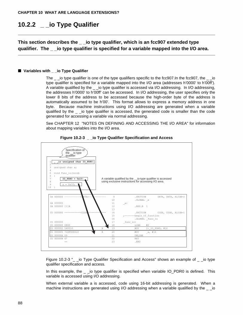
CHAPTER 10 WHAT ARE LANGUAGE EXTENSIONS?
10.2.2 _ _io Type Qualifier
This section describes the _ _io type qualifier, which is an fcc907 extended type qualifier. The _ _io type qualifier is specified for a variable mapped into the I/O area.
■ Variables with _ _io Type Qualifier
The _ _io type qualifier is one of the type qualifiers specific to the fcc907.In the fcc907, the _ _iotype qualifier is specified for a variable mapped into the I/O area (addresses h’0000’ to h’00ff’).A variable qualified by the _ _io type qualifier is accessed via I/O addressing. In I/O addressing,the addresses h’0000’ to h’00ff’ can be accessed. In I/O addressing, the user specifies only thelower 8 bits of the address to be accessed because the high-order byte of the address isautomatically assumed to be h’00’. This format allows to express a memory address in onebyte. Because machine instructions using I/O addressing are generated when a variablequalified by the _ _io type qualifier is accessed, the generated code is smaller than the codegenerated for accessing a variable via normal addressing.
See CHAPTER 12 "NOTES ON DEFINING AND ACCESSING THE I/O AREA" for informationabout mapping variables into the I/O area.
Figure 10.2-3 _ _io Type Qualifier Specification and Access
Figure 10.2-3 "_ _io Type Qualifier Specification and Access" shows an example of _ _io typequalifier specification and access.
In this example, the _ _io type qualifier is specified when variable IO_PDR0 is defined. Thisvariable is accessed using I/O addressing.
When external variable a is accessed, code using 16-bit addressing is generated. When amachine instructions are generated using I/O addressing when a variable qualified by the _ _io
A variable qualified by the __io-type qualifier is accessed using exclusive instructions for accessing I/O area.
1 _ _io unsigned char IO_PDR0;2
3 unsigned char a;
4
5 void func_io(void)
6 {
7 IO_PDR0 = 0x10;
8
9 a = 0x10;10 }
DA 000000 -----------<DATA>------------ 9 .SECTION DATA, DATA, ALIGN=2
10 .GLOBAL _a
DA 000000 11 _a:
DA 000000 [1]B 12 .RES.B 1
13
CO 000000 -----------<CODE>------------ 14 .SECTION CODE, CODE, ALIGN=1
15 ;-------begin_of_function
16 .GLOBAL _func_io
CO 000000 17 _func_io:
CO 000000 0800 18 LINK #0
CO 000002 540010 R 19 MOV I:_IO_PDR0, #16
CO 000005 71DF000010 R 20 MOV _a, #16
CO 00000A 09 21 UNLINK
CO 00000B 67 22 RET
== 23 .END
Specification of the __io type qualifier
88
10.2 Extended Type Qualifiers
type qualifier is accessed, the generated code uses I/O addressing and is therefore smaller thanthe code generated for variable access using normal addressing.
<Notes>
When defining variables with the _ _io type qualifier specified, variable areas are allocated inthe order defined. A variable such as a dummy must be defined for those locations where avariable is not defined.
[Tip]
Softune C Checker:
The Softune C Checker outputs a warning if the _ _io type qualifier, a language extension, isused in a definition and declaration. This check function is useful for creating programs forwhich portability is important.
89
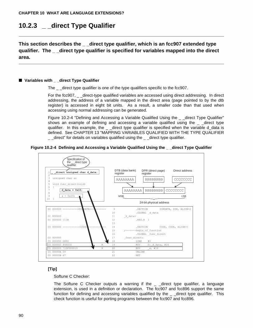
CHAPTER 10 WHAT ARE LANGUAGE EXTENSIONS?
10.2.3 _ _direct Type Qualifier
This section describes the _ _direct type qualifier, which is an fcc907 extended type qualifier. The _ _direct type qualifier is specified for variables mapped into the direct area.
■ Variables with _ _direct Type Qualifier
The _ _direct type qualifier is one of the type qualifiers specific to the fcc907.
For the fcc907, _ _direct-type qualified variables are accessed using direct addressing. In directaddressing, the address of a variable mapped in the direct area (page pointed to by the dtbregister) is accessed in eight bit units. As a result, a smaller code than that used whenaccessing using normal addressing can be generated.
Figure 10.2-4 "Defining and Accessing a Variable Qualified Using the _ _direct Type Qualifier"shows an example of defining and accessing a variable qualified using the _ _direct typequalifier. In this example, the _ _direct type qualifier is specified when the variable d_data isdefined. See CHAPTER 13 "MAPPING VARIABLES QUALIFIED WITH THE TYPE QUALIFIER_ _direct" for details on variables qualified using the _ _direct type qualifier.
Figure 10.2-4 Defining and Accessing a Variable Qualified Using the _ _direct Type Qualifier
[Tip]
Softune C Checker:
The Softune C Checker outputs a warning if the _ _direct type qualifier, a languageextension, is used in a definition or declaration. The fcc907 and fcc896 support the samefunction for defining and accessing variables qualified by the _ _direct type qualifier. Thischeck function is useful for porting programs between the fcc907 and fcc896.
DPR (direct page)register
24-bit physical address
DTB (data bank)register
Direct address1 _ _direct unsigned char d_data;2
3 unsigned char a;
4
5 void func_direct(void)
6 {
7 d_data = 0x10;
8
9 a = 0x10;
10 }
DI 000000 ----------<DIRDATA>---------- 9 .SECTION DIRDATA, DIR, ALIGN=2
10 .GLOBAL _d_data
DI 000000 11 _d_data:
DI 000000 [1]B 12 .RES.B 1
13
CO 000000 -----------<CODE>------------ 14 .SECTION CODE, CODE, ALIGN=1
15 ;-------begin_of_function
16 .GLOBAL _func_direct
CO 000000 17 _func_direct:
CO 000000 0800 18 LINK #0
CO 000002 440010 R 19 MOV S:_d_data, #16
CO 000005 71DF000010 R 20 MOV _a, #16
CO 00000A 09 21 UNLINK
CO 00000B 67 22 RET
AAAAAAAA BBBBBBBB CCCCCCCC
AAAAAAAA BBBBBBBB CCCCCCCC
MSB LSB
Specification ofthe _ _direct typequalifier
90
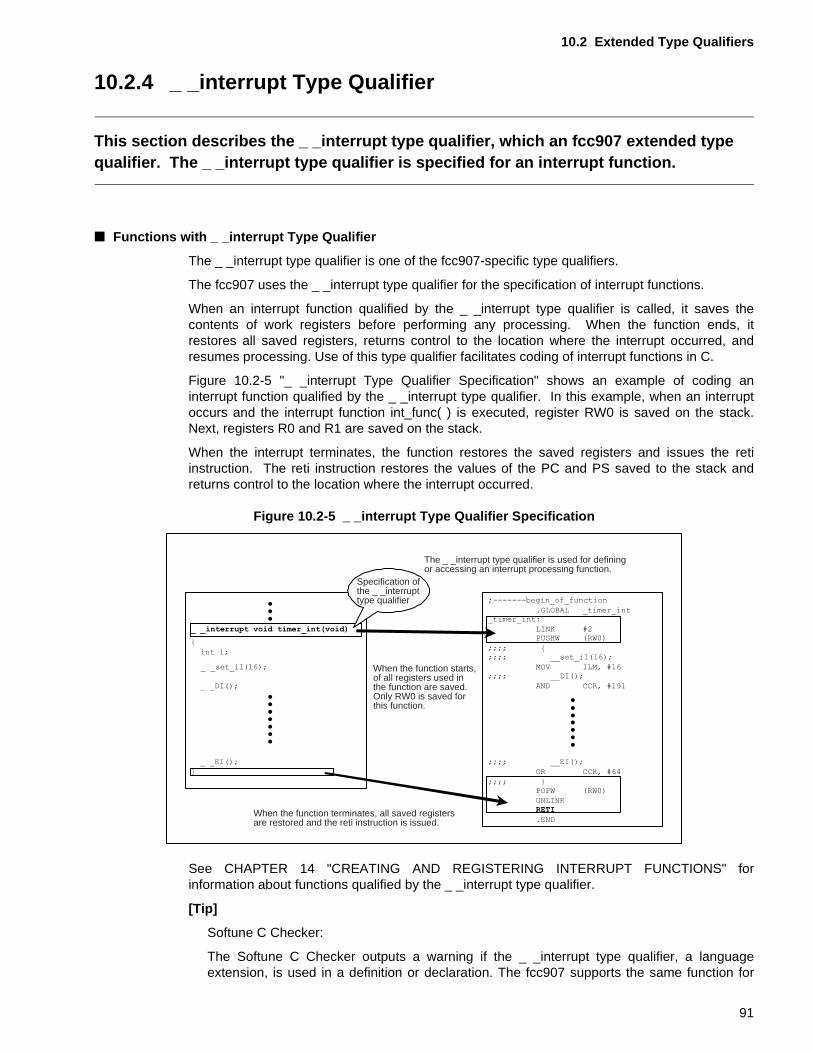
10.2 Extended Type Qualifiers
10.2.4 _ _interrupt Type Qualifier
This section describes the _ _interrupt type qualifier, which an fcc907 extended type qualifier. The _ _interrupt type qualifier is specified for an interrupt function.
■ Functions with _ _interrupt Type Qualifier
The _ _interrupt type qualifier is one of the fcc907-specific type qualifiers.
The fcc907 uses the _ _interrupt type qualifier for the specification of interrupt functions.
When an interrupt function qualified by the _ _interrupt type qualifier is called, it saves thecontents of work registers before performing any processing. When the function ends, itrestores all saved registers, returns control to the location where the interrupt occurred, andresumes processing. Use of this type qualifier facilitates coding of interrupt functions in C.
Figure 10.2-5 "_ _interrupt Type Qualifier Specification" shows an example of coding aninterrupt function qualified by the _ _interrupt type qualifier. In this example, when an interruptoccurs and the interrupt function int_func( ) is executed, register RW0 is saved on the stack.Next, registers R0 and R1 are saved on the stack.
When the interrupt terminates, the function restores the saved registers and issues the retiinstruction. The reti instruction restores the values of the PC and PS saved to the stack andreturns control to the location where the interrupt occurred.
Figure 10.2-5 _ _interrupt Type Qualifier Specification
See CHAPTER 14 "CREATING AND REGISTERING INTERRUPT FUNCTIONS" forinformation about functions qualified by the _ _interrupt type qualifier.
[Tip]
Softune C Checker:
The Softune C Checker outputs a warning if the _ _interrupt type qualifier, a languageextension, is used in a definition or declaration. The fcc907 supports the same function for
The _ _interrupt type qualifier is used for defining or accessing an interrupt processing function.
Specification of the _ _interrupt type qualifier
When the function starts, of all registers used in the function are saved. Only RW0 is saved for this function.
When the function terminates, all saved registers are restored and the reti instruction is issued.
91
CHAPTER 10 WHAT ARE LANGUAGE EXTENSIONS?
coding interrupt functions qualified by the _ _interrupt-type as the fcc896 and fcc911. Thischeck function is useful for porting programs between the fcc896 or fcc911 and fcc896.
92
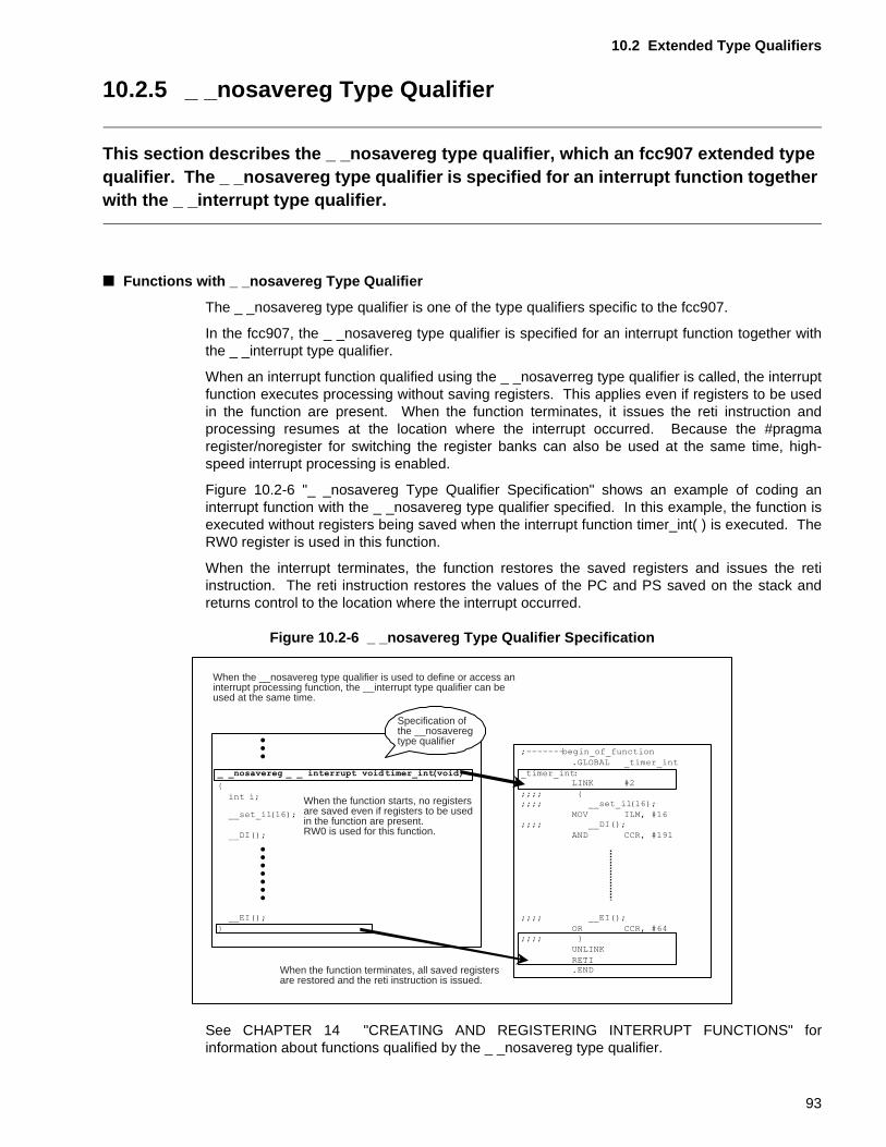
10.2 Extended Type Qualifiers
10.2.5 _ _nosavereg Type Qualifier
This section describes the _ _nosavereg type qualifier, which an fcc907 extended type qualifier. The _ _nosavereg type qualifier is specified for an interrupt function together with the _ _interrupt type qualifier.
■ Functions with _ _nosavereg Type Qualifier
The _ _nosavereg type qualifier is one of the type qualifiers specific to the fcc907.
In the fcc907, the _ _nosavereg type qualifier is specified for an interrupt function together withthe _ _interrupt type qualifier.
When an interrupt function qualified using the _ _nosaverreg type qualifier is called, the interruptfunction executes processing without saving registers. This applies even if registers to be usedin the function are present. When the function terminates, it issues the reti instruction andprocessing resumes at the location where the interrupt occurred. Because the #pragmaregister/noregister for switching the register banks can also be used at the same time, high-speed interrupt processing is enabled.
Figure 10.2-6 "_ _nosavereg Type Qualifier Specification" shows an example of coding aninterrupt function with the _ _nosavereg type qualifier specified. In this example, the function isexecuted without registers being saved when the interrupt function timer_int( ) is executed. TheRW0 register is used in this function.
When the interrupt terminates, the function restores the saved registers and issues the retiinstruction. The reti instruction restores the values of the PC and PS saved on the stack andreturns control to the location where the interrupt occurred.
Figure 10.2-6 _ _nosavereg Type Qualifier Specification
See CHAPTER 14 "CREATING AND REGISTERING INTERRUPT FUNCTIONS" forinformation about functions qualified by the _ _nosavereg type qualifier.
When the function terminates, all saved registers are restored and the reti instruction is issued.
Specification of the __nosavereg type qualifier
When the function starts, no registers are saved even if registers to be used in the function are present. RW0 is used for this function.
When the __nosavereg type qualifier is used to define or access an interrupt processing function, the __interrupt type qualifier can be used at the same time.
93
CHAPTER 10 WHAT ARE LANGUAGE EXTENSIONS?
[Tip]
Softune C Checker:
The Softune C Checker outputs a warning if the _ _nosavereg type qualifier, a languageextension, is used in a definition or declaration. The fcc907 supports the same function forcoding interrupt functions qualified by the _ _nosavereg type qualifier as the fcc896. Thischeck function is useful for porting programs between the fcc907 and fcc896.
94
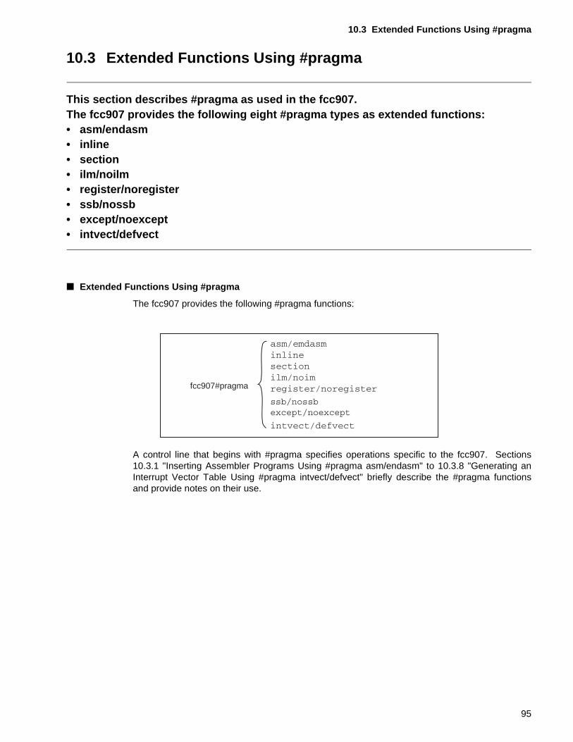
10.3 Extended Functions Using #pragma
10.3 Extended Functions Using #pragma
This section describes #pragma as used in the fcc907.The fcc907 provides the following eight #pragma types as extended functions:• asm/endasm• inline• section• ilm/noilm• register/noregister• ssb/nossb• except/noexcept• intvect/defvect
■ Extended Functions Using #pragma
The fcc907 provides the following #pragma functions:
A control line that begins with #pragma specifies operations specific to the fcc907. Sections10.3.1 "Inserting Assembler Programs Using #pragma asm/endasm" to 10.3.8 "Generating anInterrupt Vector Table Using #pragma intvect/defvect" briefly describe the #pragma functionsand provide notes on their use.
fcc907#pragma
95
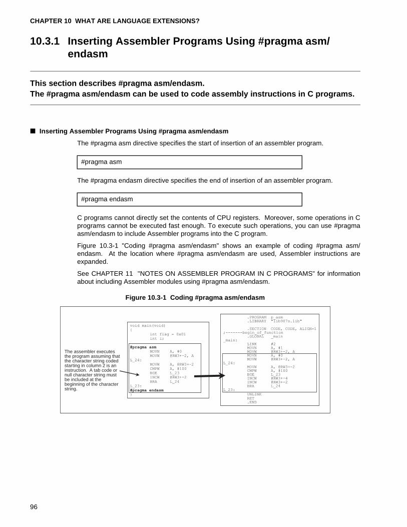
CHAPTER 10 WHAT ARE LANGUAGE EXTENSIONS?
10.3.1 Inserting Assembler Programs Using #pragma asm/endasm
This section describes #pragma asm/endasm.The #pragma asm/endasm can be used to code assembly instructions in C programs.
■ Inserting Assembler Programs Using #pragma asm/endasm
The #pragma asm directive specifies the start of insertion of an assembler program.
The #pragma endasm directive specifies the end of insertion of an assembler program.
C programs cannot directly set the contents of CPU registers. Moreover, some operations in Cprograms cannot be executed fast enough. To execute such operations, you can use #pragmaasm/endasm to include Assembler programs into the C program.
Figure 10.3-1 "Coding #pragma asm/endasm" shows an example of coding #pragma asm/endasm. At the location where #pragma asm/endasm are used, Assembler instructions areexpanded.
See CHAPTER 11 "NOTES ON ASSEMBLER PROGRAM IN C PROGRAMS" for informationabout including Assembler modules using #pragma asm/endasm.
Figure 10.3-1 Coding #pragma asm/endasm
#pragma asm
#pragma endasm
The assembler executesthe program assuming thatthe character string codedstarting in column 2 is aninstruction. A tab code ornull character string mustbe included at thebeginning of the characterstring.
void main(void){
int flag = 0x01int i;
#pragma asmMOVN A, #0MOVW @RW3+-2, A
L_24:MOVW A, @RW3+-2CMPW A, #100BGE L_23INCW @RW3+-2BRA L_24
L_23:#pragma endasm}
.PROGRAM p_asm
.LIBRARY "lib907s.lib"
.SECTION CODE, CODE, ALIGN=1;-------begin_of_function
.GLOBAL _main_main:
LINK #2MOVN A, #1MOVW @RW3+-2, AMOVN A, #0MOVW @RW3+-2, A
L_24:MOVW A, @RW3+-2CMPW A, #100BGE L_23INCW @RW3+-4INCW @RW3+-2BRA L_24
L_23:UNLINKRET.END
96
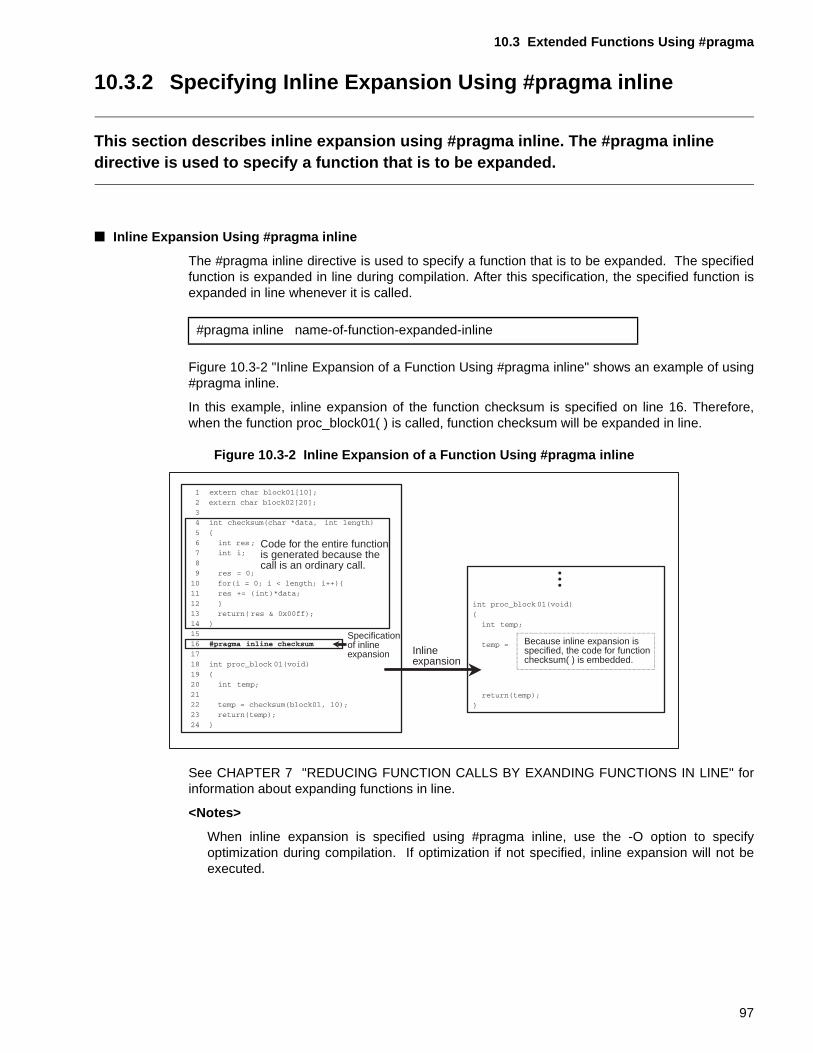
10.3 Extended Functions Using #pragma
10.3.2 Specifying Inline Expansion Using #pragma inline
This section describes inline expansion using #pragma inline. The #pragma inline directive is used to specify a function that is to be expanded.
■ Inline Expansion Using #pragma inline
The #pragma inline directive is used to specify a function that is to be expanded. The specifiedfunction is expanded in line during compilation. After this specification, the specified function isexpanded in line whenever it is called.
Figure 10.3-2 "Inline Expansion of a Function Using #pragma inline" shows an example of using#pragma inline.
In this example, inline expansion of the function checksum is specified on line 16. Therefore,when the function proc_block01( ) is called, function checksum will be expanded in line.
Figure 10.3-2 Inline Expansion of a Function Using #pragma inline
See CHAPTER 7 "REDUCING FUNCTION CALLS BY EXANDING FUNCTIONS IN LINE" forinformation about expanding functions in line.
<Notes>
When inline expansion is specified using #pragma inline, use the -O option to specifyoptimization during compilation. If optimization if not specified, inline expansion will not beexecuted.
#pragma inline name-of-function-expanded-inline
Code for the entire functionis generated because thecall is an ordinary call.
Specificationof inlineexpansion Inline
expansion
Because inline expansion isspecified, the code for functionchecksum( ) is embedded.
97
CHAPTER 10 WHAT ARE LANGUAGE EXTENSIONS?
[Tip]
For the fcc907:
The following option can be used to specify the function to be expanded in line duringcompilation.
Use the following option to specify the number of lines of the function to be expanded in lineduring compilation.
Optimization must be specified using the -O option.
-x function-name option
-xauto size option
98
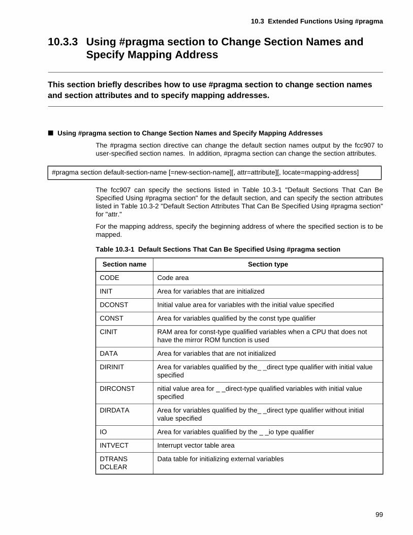
10.3 Extended Functions Using #pragma
10.3.3 Using #pragma section to Change Section Names and Specify Mapping Address
This section briefly describes how to use #pragma section to change section names and section attributes and to specify mapping addresses.
■ Using #pragma section to Change Section Names and Specify Mapping Addresses
The #pragma section directive can change the default section names output by the fcc907 touser-specified section names. In addition, #pragma section can change the section attributes.
The fcc907 can specify the sections listed in Table 10.3-1 "Default Sections That Can BeSpecified Using #pragma section" for the default section, and can specify the section attributeslisted in Table 10.3-2 "Default Section Attributes That Can Be Specified Using #pragma section"for "attr."
For the mapping address, specify the beginning address of where the specified section is to bemapped.
#pragma section default-section-name [=new-section-name][, attr=attribute][, locate=mapping-address]
Table 10.3-1 Default Sections That Can Be Specified Using #pragma section
Section name Section type
CODE Code area
INIT Area for variables that are initialized
DCONST Initial value area for variables with the initial value specified
CONST Area for variables qualified by the const type qualifier
CINIT RAM area for const-type qualified variables when a CPU that does not have the mirror ROM function is used
DATA Area for variables that are not initialized
DIRINIT Area for variables qualified by the_ _direct type qualifier with initial value specified
DIRCONST nitial value area for _ _direct-type qualified variables with initial value specified
DIRDATA Area for variables qualified by the_ _direct type qualifier without initial value specified
IO Area for variables qualified by the _ _io type qualifier
INTVECT Interrupt vector table area
DTRANSDCLEAR
Data table for initializing external variables
99
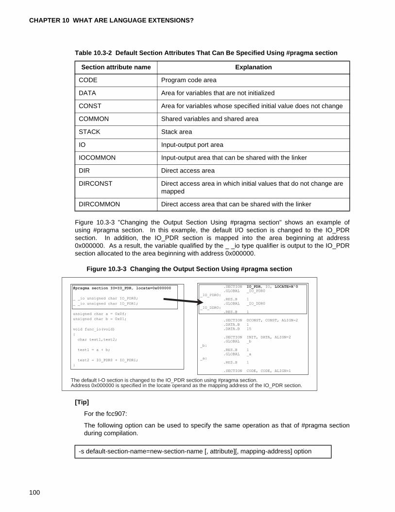
CHAPTER 10 WHAT ARE LANGUAGE EXTENSIONS?
Figure 10.3-3 "Changing the Output Section Using #pragma section" shows an example ofusing #pragma section. In this example, the default I/O section is changed to the IO_PDRsection. In addition, the IO_PDR section is mapped into the area beginning at address0x000000. As a result, the variable qualified by the _ _io type qualifier is output to the IO_PDRsection allocated to the area beginning with address 0x000000.
Figure 10.3-3 Changing the Output Section Using #pragma section
[Tip]
For the fcc907:
The following option can be used to specify the same operation as that of #pragma sectionduring compilation.
Table 10.3-2 Default Section Attributes That Can Be Specified Using #pragma section
Section attribute name Explanation
CODE Program code area
DATA Area for variables that are not initialized
CONST Area for variables whose specified initial value does not change
COMMON Shared variables and shared area
STACK Stack area
IO Input-output port area
IOCOMMON Input-output area that can be shared with the linker
DIR Direct access area
DIRCONST Direct access area in which initial values that do not change are mapped
DIRCOMMON Direct access area that can be shared with the linker
The default I-O section is changed to the IO_PDR section using #pragma section.Address 0x000000 is specified in the locate operand as the mapping address of the IO_PDR section.
#pragma section IO=IO_PDR, locate=0x000000
_ _io unsigned char IO_PDR0;
_ _io unsigned char IO_PDR1;
unsigned char a = 0x0f;
unsigned char b = 0x01;
void func_io(void)
{
char test1,test2;
test1 = a + b;
test2 = IO_PDR0 + IO_PDR1;
}
.SECTION IO_PDR, IO, LOCATE=H'0
.GLOBAL _IO_PDR0_IO_PDR0:
.RES.B 1
.GLOBAL _IO_DDR0_IO_DDR0:
.RES.B 1
.SECTION DCONST, CONST, ALIGN=2
.DATA.B 1
.DATA.B 15
.SECTION INIT, DATA, ALIGN=2
.GLOBAL _b_b:
.RES.B 1
.GLOBAL _a_a:
.RES.B 1
.SECTION CODE, CODE, ALIGN=1
-s default-section-name=new-section-name [, attribute][, mapping-address] option
100
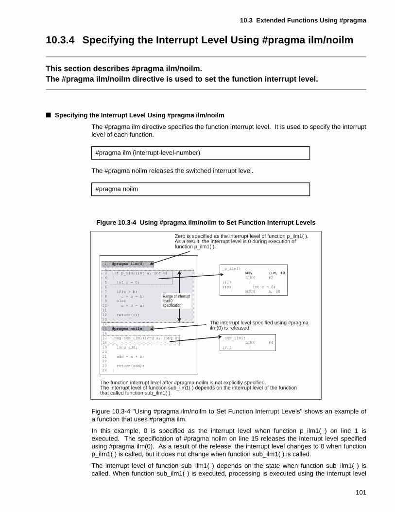
10.3 Extended Functions Using #pragma
10.3.4 Specifying the Interrupt Level Using #pragma ilm/noilm
This section describes #pragma ilm/noilm.The #pragma ilm/noilm directive is used to set the function interrupt level.
■ Specifying the Interrupt Level Using #pragma ilm/noilm
The #pragma ilm directive specifies the function interrupt level. It is used to specify the interruptlevel of each function.
The #pragma noilm releases the switched interrupt level.
Figure 10.3-4 Using #pragma ilm/noilm to Set Function Interrupt Levels
Figure 10.3-4 "Using #pragma ilm/noilm to Set Function Interrupt Levels" shows an example ofa function that uses #pragma ilm.
In this example, 0 is specified as the interrupt level when function p_ilm1( ) on line 1 isexecuted. The specification of #pragma noilm on line 15 releases the interrupt level specifiedusing #pragma ilm(0). As a result of the release, the interrupt level changes to 0 when functionp_ilm1( ) is called, but it does not change when function sub_ilm1( ) is called.
The interrupt level of function sub_ilm1( ) depends on the state when function sub_ilm1( ) iscalled. When function sub_ilm1( ) is executed, processing is executed using the interrupt level
#pragma ilm (interrupt-level-number)
#pragma noilm
Zero is specified as the interrupt level of function p_ilm1( ).As a result, the interrupt level is 0 during execution of function p_ilm1( ).
The interrupt level specified using #pragmailm(0) is released.
The function interrupt level after #pragma noilm is not explicitly specified.The interrupt level of function sub_ilm1( ) depends on the interrupt level of the functionthat called function sub_ilm1( ).
1 #pragma ilm(0)
2
3 int p_ilm1(int a, int b)
4 {
5 int c = 0;
6
7 if(a > b)
8 c = a - b;9 else
10 c = b - a;
11
12 return(c);13 }
14
15 #pragma noilm
16
17 long sub_ilm1(long a, long b)
18 {
19 long add;
20
21 add = a + b;
22
23 return(add);
24 }
_p_ilm1:
MOV ILM, #0
LINK #2
;;;; {
;;;; int c = 0;
MOVN A, #0
_sub_ilm1:LINK #4
;;;; {
Range of interruptlevel 0specification
101
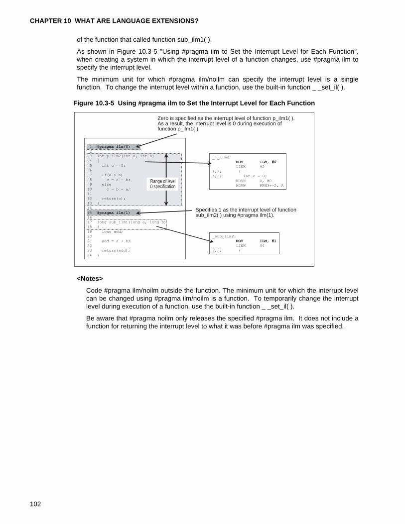
CHAPTER 10 WHAT ARE LANGUAGE EXTENSIONS?
of the function that called function sub_ilm1( ).
As shown in Figure 10.3-5 "Using #pragma ilm to Set the Interrupt Level for Each Function",when creating a system in which the interrupt level of a function changes, use #pragma ilm tospecify the interrupt level.
The minimum unit for which #pragma ilm/noilm can specify the interrupt level is a singlefunction. To change the interrupt level within a function, use the built-in function _ _set_il( ).
Figure 10.3-5 Using #pragma ilm to Set the Interrupt Level for Each Function
<Notes>
Code #pragma ilm/noilm outside the function. The minimum unit for which the interrupt levelcan be changed using #pragma ilm/noilm is a function. To temporarily change the interruptlevel during execution of a function, use the built-in function _ _set_il( ).
Be aware that #pragma noilm only releases the specified #pragma ilm. It does not include afunction for returning the interrupt level to what it was before #pragma ilm was specified.
Zero is specified as the interrupt level of function p_ilm1( ).As a result, the interrupt level is 0 during execution of function p_ilm1( ).
Specifies 1 as the interrupt level of functionsub_ilm2( ) using #pragma ilm(1).
1 #pragma ilm(0)
23 int p_ilm2(int a, int b)
4 {
5 int c = 0;
6
7 if(a > b)
8 c = a - b;
9 else
10 c = b - a;
11
12 return(c);
13 }
14
15 #pragma ilm(1)
16
17 long sub_ilm1(long a, long b)
18 {
19 long add;
20
21 add = a + b;
22
23 return(add);
24 }
_p_ilm2:
MOV ILM, #0
LINK #2
;;;; {;;;; int c = 0;
MOVN A, #0
MOVW @RW3+-2, A
_sub_ilm2:
MOV ILM, #1
LINK #4
;;;; {
Range of level0 specification
102
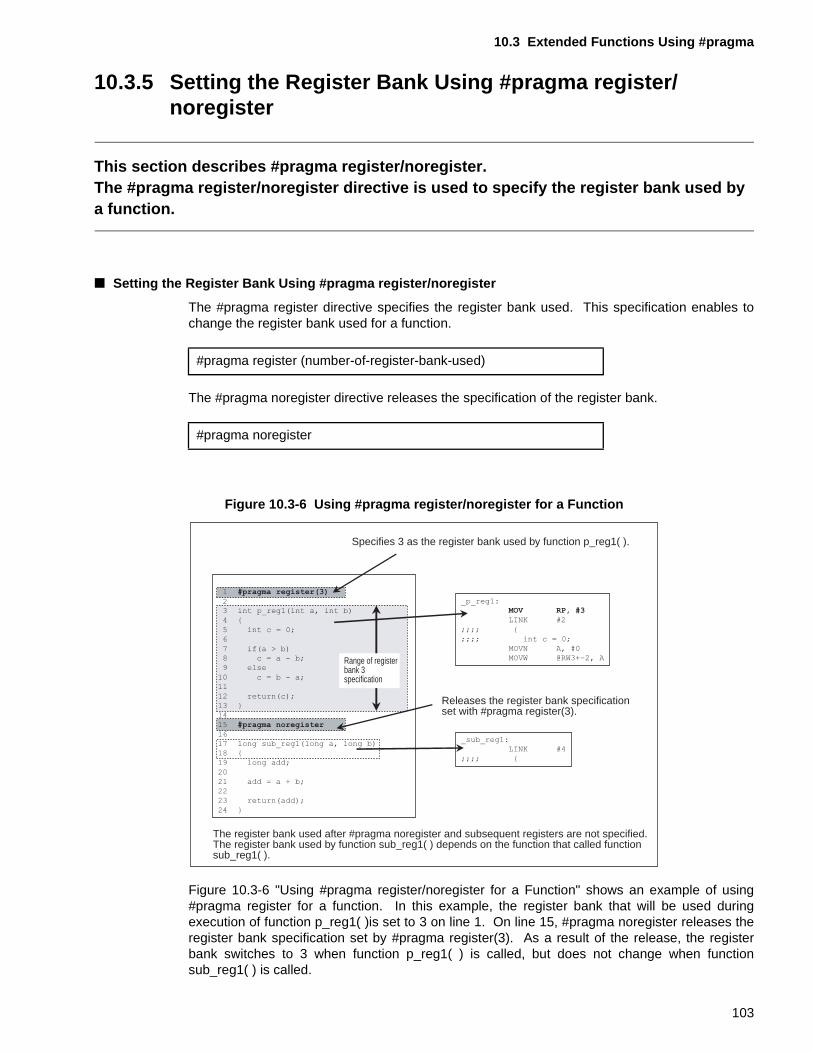
10.3 Extended Functions Using #pragma
10.3.5 Setting the Register Bank Using #pragma register/noregister
This section describes #pragma register/noregister.The #pragma register/noregister directive is used to specify the register bank used by a function.
■ Setting the Register Bank Using #pragma register/noregister
The #pragma register directive specifies the register bank used. This specification enables tochange the register bank used for a function.
The #pragma noregister directive releases the specification of the register bank.
Figure 10.3-6 Using #pragma register/noregister for a Function
Figure 10.3-6 "Using #pragma register/noregister for a Function" shows an example of using#pragma register for a function. In this example, the register bank that will be used duringexecution of function p_reg1( )is set to 3 on line 1. On line 15, #pragma noregister releases theregister bank specification set by #pragma register(3). As a result of the release, the registerbank switches to 3 when function p_reg1( ) is called, but does not change when functionsub_reg1( ) is called.
#pragma register (number-of-register-bank-used)
#pragma noregister
Specifies 3 as the register bank used by function p_reg1( ).
Releases the register bank specificationset with #pragma register(3).
The register bank used after #pragma noregister and subsequent registers are not specified.The register bank used by function sub_reg1( ) depends on the function that called functionsub_reg1( ).
1 #pragma register(3)
23 int p_reg1(int a, int b)
4 {
5 int c = 0;
6
7 if(a > b)
8 c = a - b;
9 else
10 c = b - a;
11
12 return(c);
13 }
14
15 #pragma noregister
16
17 long sub_reg1(long a, long b)
18 {
19 long add;
20
21 add = a + b;
22
23 return(add);
24 }
_p_reg1:MOV RP, #3
LINK #2
;;;; {
;;;; int c = 0;
MOVN A, #0
MOVW @RW3+-2, A
_sub_reg1:
LINK #4
;;;; {
Range of registerbank 3specification
103
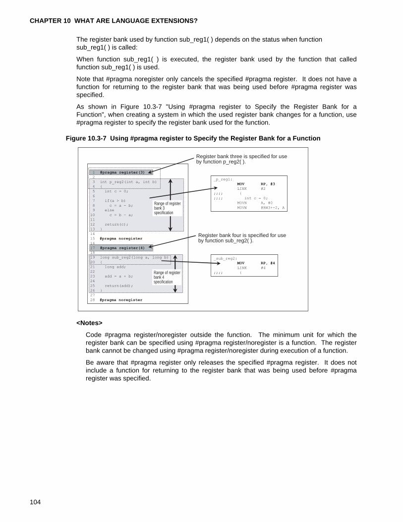
CHAPTER 10 WHAT ARE LANGUAGE EXTENSIONS?
The register bank used by function sub_reg1( ) depends on the status when function sub_reg1( ) is called:
When function sub_reg1( ) is executed, the register bank used by the function that calledfunction sub_reg1( ) is used.
Note that #pragma noregister only cancels the specified #pragma register. It does not have afunction for returning to the register bank that was being used before #pragma register wasspecified.
As shown in Figure 10.3-7 "Using #pragma register to Specify the Register Bank for aFunction", when creating a system in which the used register bank changes for a function, use#pragma register to specify the register bank used for the function.
Figure 10.3-7 Using #pragma register to Specify the Register Bank for a Function
<Notes>
Code #pragma register/noregister outside the function. The minimum unit for which theregister bank can be specified using #pragma register/noregister is a function. The registerbank cannot be changed using #pragma register/noregister during execution of a function.
Be aware that #pragma register only releases the specified #pragma register. It does notinclude a function for returning to the register bank that was being used before #pragmaregister was specified.
Register bank three is specified for use by function p_reg2( ).
Register bank four is specified for useby function sub_reg2( ).
1 #pragma register(3)
2
3 int p_reg2(int a, int b)
4 {
5 int c = 0;
6
7 if(a > b)
8 c = a - b;9 else
10 c = b - a;
11
12 return(c);
13 }
14
15 #pragma noregister
16
17 #pragma register(4)
18
19 long sub_reg2(long a, long b)
20 {
21 long add;
22
23 add = a + b;
24
25 return(add);
26 }
27
28 #pragma noregister
_p_reg1:
MOV RP, #3
LINK #2
;;;; {
;;;; int c = 0;
MOVN A, #0
MOVW @RW3+-2, A
_sub_reg2:
MOV RP, #4
LINK #4
;;;; {
Range of registerbank 3specification
Range of registerbank 4 specification
104
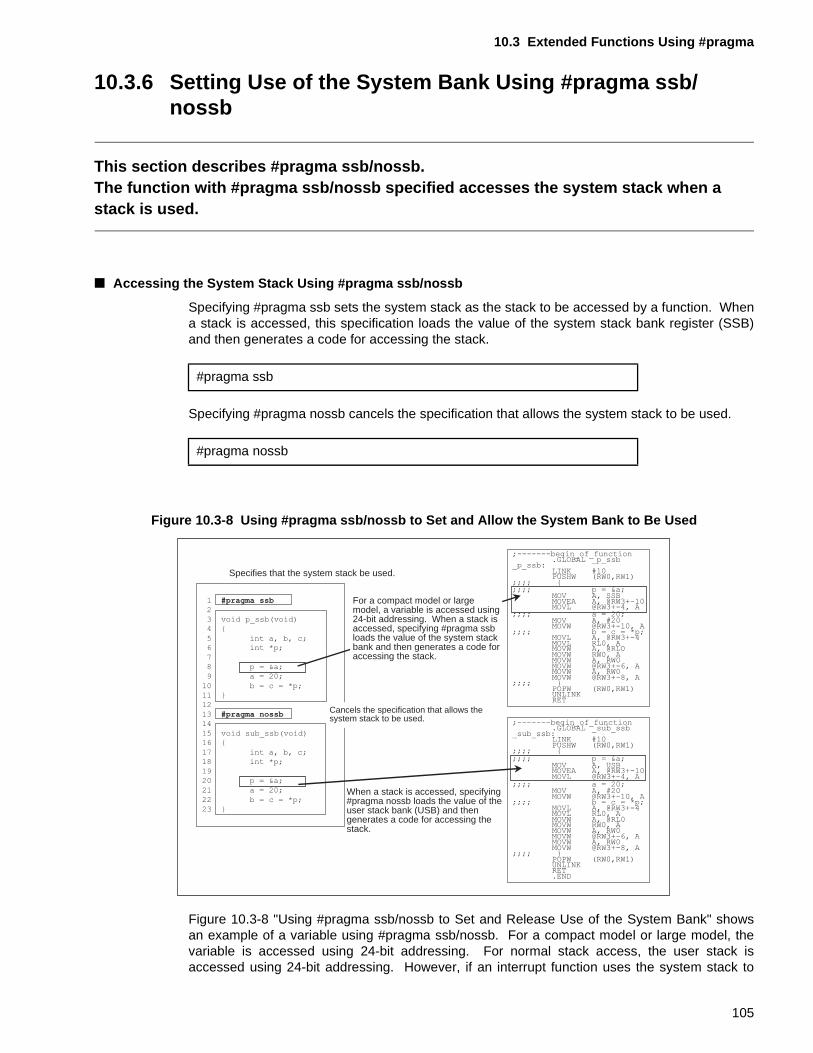
10.3 Extended Functions Using #pragma
10.3.6 Setting Use of the System Bank Using #pragma ssb/nossb
This section describes #pragma ssb/nossb.The function with #pragma ssb/nossb specified accesses the system stack when a stack is used.
■ Accessing the System Stack Using #pragma ssb/nossb
Specifying #pragma ssb sets the system stack as the stack to be accessed by a function. Whena stack is accessed, this specification loads the value of the system stack bank register (SSB)and then generates a code for accessing the stack.
Specifying #pragma nossb cancels the specification that allows the system stack to be used.
Figure 10.3-8 Using #pragma ssb/nossb to Set and Allow the System Bank to Be Used
Figure 10.3-8 "Using #pragma ssb/nossb to Set and Release Use of the System Bank" showsan example of a variable using #pragma ssb/nossb. For a compact model or large model, thevariable is accessed using 24-bit addressing. For normal stack access, the user stack isaccessed using 24-bit addressing. However, if an interrupt function uses the system stack to
#pragma ssb
#pragma nossb
Specifies that the system stack be used.
When a stack is accessed, specifying #pragma nossb loads the value of the user stack bank (USB) and then generates a code for accessing the stack.
For a compact model or large model, a variable is accessed using 24-bit addressing. When a stack is accessed, specifying #pragma ssb loads the value of the system stack bank and then generates a code for accessing the stack.
1 #pragma ssb
2
3 void p_ssb(void)
4 {
5 int a, b, c;6 int *p;
7
8 p = &a;
9 a = 20;
10 b = c = *p;
11 }
12
13 #pragma nossb
14
15 void sub_ssb(void)16 {
17 int a, b, c;
18 int *p;
19
20 p = &a;
21 a = 20;
22 b = c = *p;
23 }
;-------begin_of_function.GLOBAL _sub_ssb
_sub_ssb:LINK #10PUSHW (RW0,RW1)
;;;; {;;;; p = &a;
MOV A, USBMOVEA A, @RW3+-10MOVL @RW3+-4, A
;;;; a = 20;MOV A, #20MOVW @RW3+-10, A
;;;; b = c = *p;MOVL A, @RW3+-4MOVL RL0, AMOVW A, @RL0MOVW RW0, AMOVW A, RW0MOVW @RW3+-6, AMOVW A, RW0MOVW @RW3+-8, A
;;;; }POPW (RW0,RW1)UNLINKRET.END
;-------begin_of_function.GLOBAL _p_ssb
_p_ssb:LINK #10PUSHW (RW0,RW1)
;;;; {;;;; p = &a;
MOV A, SSBMOVEA A, @RW3+-10MOVL @RW3+-4, A
;;;; a = 20;MOV A, #20MOVW @RW3+-10, A
;;;; b = c = *p;MOVL A, @RW3+-4MOVL RL0, AMOVW A, @RL0MOVW RW0, AMOVW A, RW0MOVW @RW3+-6, AMOVW A, RW0MOVW @RW3+-8, A
;;;; }POPW (RW0,RW1)UNLINKRET
Cancels the specification that allows the system stack to be used.
105
CHAPTER 10 WHAT ARE LANGUAGE EXTENSIONS?
execute processing, the system stack must be accessed using 24-bit addressing. In suchcases, #pragma ssb/nossb is specified to load the value of the SSB register and generate acode for accessing the stack when the stack is accessed.
In this example, #pragma ssb is specified on line 1 to specify use of the system stack when thefunction p_ssb( ) is executed. On line 13, #pragma nossb is specified to cancel thespecification, that allows the system stack to be used, given by #pragma ssb. Then, when thefunction p_ssb( ) is called and the stack accessed, the SSB register value will be loaded and acode for accessing the stack is generated. If the function sub_ssb( ) is called, however, thevalue of the user stack bank register (USB register) will be loaded and a code for accessing thestack is generated.
<Notes>
When #pragma ssb/nossb is specified to generate a code for accessing the system stack,specify a compact or a large model at compilation. If a compact model or large model is notspecified, a code for 16-bit addressing will be generated.
106
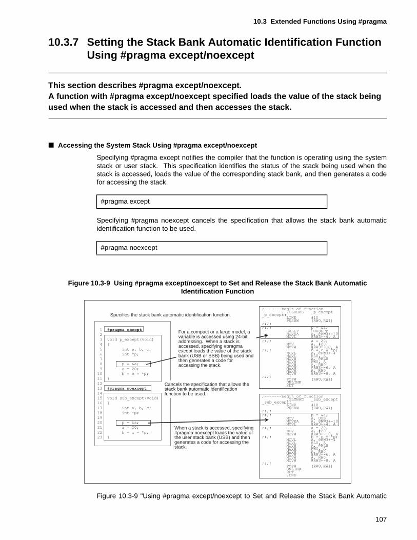
10.3 Extended Functions Using #pragma
10.3.7 Setting the Stack Bank Automatic Identification Function Using #pragma except/noexcept
This section describes #pragma except/noexcept.A function with #pragma except/noexcept specified loads the value of the stack being used when the stack is accessed and then accesses the stack.
■ Accessing the System Stack Using #pragma except/noexcept
Specifying #pragma except notifies the compiler that the function is operating using the systemstack or user stack. This specification identifies the status of the stack being used when thestack is accessed, loads the value of the corresponding stack bank, and then generates a codefor accessing the stack.
Specifying #pragma noexcept cancels the specification that allows the stack bank automaticidentification function to be used.
Figure 10.3-9 Using #pragma except/noexcept to Set and Release the Stack Bank Automatic Identification Function
Figure 10.3-9 "Using #pragma except/noexcept to Set and Release the Stack Bank Automatic
#pragma except
#pragma noexcept
Specifies the stack bank automatic identification function.
When a stack is accessed, specifying #pragma noexcept loads the value of the user stack bank (USB) and then generates a code for accessing the stack.
1 #pragma except
23 void p_except(void)
4 {
5 int a, b, c;
6 int *p;
7
8 p = &a;
9 a = 20;
10 b = c = *p;11 }
12
13 #pragma noexcept
1415 void sub_except(void)
16 {
17 int a, b, c;
18 int *p;
19
20 p = &a;
21 a = 20;
22 b = c = *p;
23 }
;-------begin_of_function.GLOBAL _sub_except
_sub_except:LINK #10PUSHW (RW0,RW1)
;;;; {;;;; p = &a;
MOV A, USBMOVEA A, @RW3+-10MOVL @RW3+-4, A
;;;; a = 20;MOV A, #20MOVW @RW3+-10, A
;;;; b = c = *p;MOVL A, @RW3+-4MOVL RL0, AMOVW A, @RL0MOVW RW0, AMOVW A, RW0MOVW @RW3+-6, AMOVW A, RW0MOVW @RW3+-8, A
;;;; }POPW (RW0,RW1)UNLINKRET.END
;-------begin_of_function.GLOBAL _p_except
_p_except:LINK #10PUSHW (RW0,RW1)
;;;; {;;;; p = &a;
CALLP LOADSPBMOVEA A, @RW3+-10MOVL @RW3+-4, A
;;;; a = 20;MOV A, #20MOVW @RW3+-10, A
;;;; b = c = *p;MOVL A, @RW3+-4MOVL RL0, AMOVW A, @RL0MOVW RW0, AMOVW A, RW0MOVW @RW3+-6, AMOVW A, RW0MOVW @RW3+-8, A
;;;; }POPW (RW0,RW1)UNLINKRETCancels the specification that allows the
stack bank automatic identification function to be used.
For a compact or a large model, a variable is accessed using 24-bit addressing. When a stack is accessed, specifying #pragma except loads the value of the stack bank (USB or SSB) being used and then generates a code for accessing the stack.
107
CHAPTER 10 WHAT ARE LANGUAGE EXTENSIONS?
Identification Function" shows an example of a variable using #pragma except/noexcept. For acompact or a large model, the variable is accessed using 24-bit addressing. For normal stackaccess, the user stack bank register (USB register) is used to access the user stack using 24-bitaddressing. However, for an exception handler created using REALOS, the stack that isaccessed depends on the activation status. In such cases, #pragma except/noexcept isspecified to load the value of the stack bank register being used and generate a code foraccessing the stack when the stack is accessed.
In this example, #pragma except is specified on line 1. This specification generates a code forautomatically identifying the stack bank when the function p_except( ) is executed. On line 13,#pragma noexcept is specified to release specification of the stack bank automatic identificationfunction specified by #pragma except. Then, when the function p_except( ) is called, the statusof the stack being used is identified. As a result, the value of the stack bank being used will beloaded and a code for accessing the stack is generated. If the function sub_except( ) is called,however, the value of the user stack bank register (USB register) will be loaded and a code foraccessing the stack is generated.
<Notes>
When #pragma except/noexcept is specified to use the automatic identification function forthe stack being used, specify a compact model or large model at compilation to generatecode for accessing the stack using 24-bit addressing. If a compact or a large model is notspecified, a code for 16-bit addressing will be generated.
108
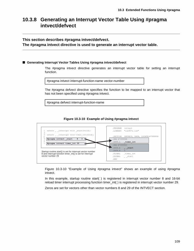
10.3 Extended Functions Using #pragma
10.3.8 Generating an Interrupt Vector Table Using #pragma intvect/defvect
This section describes #pragma intvect/defvect.The #pragma intvect directive is used to generate an interrupt vector table.
■ Generating Interrupt Vector Tables Using #pragma intvect/defvect
The #pragma intvect directive generates an interrupt vector table for setting an interruptfunction.
The #pragma defvect directive specifies the function to be mapped to an interrupt vector thathas not been specified using #pragma intvect.
Figure 10.3-10 Example of Using #pragma intvect
Figure 10.3-10 "Example of Using #pragma intvect" shows an example of using #pragmaintvect.
In this example, startup routine start( ) is registered in interrupt vector number 8 and 16-bitreload timer interrupt processing function timer_int( ) is registered in interrupt vector number 29.
Zeros are set for vectors other than vector numbers 8 and 29 of the INTVECT section.
#pragma intvect interrupt-function-name vector-number
#pragma defvect interrupt-function-name
Startup routine start() is set for interrupt vector number 8 and interrupt function timer_int() is set for interrupt vector number 29
1 extern _ _interrupt void _start(void);23 extern _ _interrupt void timer_int(void);4
65 #pragma intvect _start 8 0
7 #pragma intvect timer_int 29
.PROGRAM intvect
.LIBRARY "lib907s.lib"
.SECTION INTVECT, DATA, LOCATE=H'FFFF88
.ORG H'FFFF88
.DATA.L _timer_int
.ORG H'FFFFDC
.DATA.E _ _start
.DATA.B 0
.GLOBAL _timer_int
.GLOBAL _ _start
.END
109
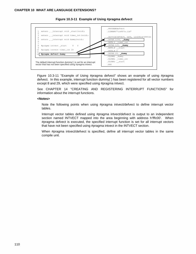
CHAPTER 10 WHAT ARE LANGUAGE EXTENSIONS?
Figure 10.3-11 Example of Using #pragma defvect
Figure 10.3-11 "Example of Using #pragma defvect" shows an example of using #pragmadefvect. In this example, interrupt function dummy( ) has been registered for all vector numbersexcept 8 and 29, which were specified using #pragma intvect.
See CHAPTER 14 "CREATING AND REGISTERING INTERRUPT FUNCTIONS" forinformation about the interrupt functions.
<Notes>
Note the following points when using #pragma intvect/defvect to define interrupt vectortables.
Interrupt vector tables defined using #pragma intvect/defvect is output to an independentsection named INTVECT mapped into the area beginning with address h’fffc00’. When#pragma defvect is executed, the specified interrupt function is set for all interrupt vectorsthat have not been specified using #pragma intvect in the INTVECT section.
When #pragma intvect/defvect is specified, define all interrupt vector tables in the samecompile unit.
The default interrupt function dummy( ) is set for an interruptvector that has not been specified using #pragma intvect.
110
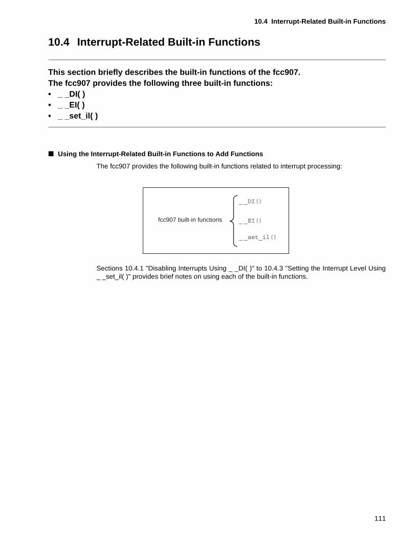
10.4 Interrupt-Related Built-in Functions
10.4 Interrupt-Related Built-in Functions
This section briefly describes the built-in functions of the fcc907.The fcc907 provides the following three built-in functions:• _ _DI( )• _ _EI( )• _ _set_il( )
■ Using the Interrupt-Related Built-in Functions to Add Functions
The fcc907 provides the following built-in functions related to interrupt processing:
Sections 10.4.1 "Disabling Interrupts Using _ _DI( )" to 10.4.3 "Setting the Interrupt Level Using_ _set_il( )" provides brief notes on using each of the built-in functions.
fcc907 built-in functions
111
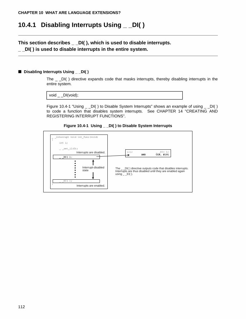
CHAPTER 10 WHAT ARE LANGUAGE EXTENSIONS?
10.4.1 Disabling Interrupts Using _ _DI( )
This section describes _ _DI( ), which is used to disable interrupts._ _DI( ) is used to disable interrupts in the entire system.
■ Disabling Interrupts Using _ _DI( )
The _ _DI( ) directive expands code that masks interrupts, thereby disabling interrupts in theentire system.
Figure 10.4-1 "Using _ _DI( ) to Disable System Interrupts" shows an example of using _ _DI( )to code a function that disables system interrupts. See CHAPTER 14 "CREATING ANDREGISTERING INTERRUPT FUNCTIONS".
Figure 10.4-1 Using _ _DI( ) to Disable System Interrupts
void _ _DI(void);
Interrupts are disabled.
Interrupt-disabledstate
Interrupts are enabled.
The _ _DI( ) directive outputs code that disables interrupts.Interrupts are thus disabled until they are enabled again using _ _EI( ).
112
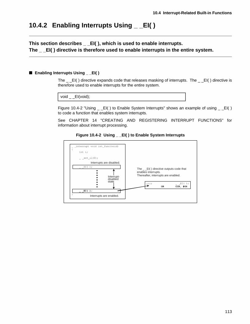
10.4 Interrupt-Related Built-in Functions
10.4.2 Enabling Interrupts Using _ _EI( )
This section describes _ _EI( ), which is used to enable interrupts. The _ _EI( ) directive is therefore used to enable interrupts in the entire system.
■ Enabling Interrupts Using _ _EI( )
The _ _EI( ) directive expands code that releases masking of interrupts. The _ _EI( ) directive istherefore used to enable interrupts for the entire system.
Figure 10.4-2 "Using _ _EI( ) to Enable System Interrupts" shows an example of using _ _EI( )to code a function that enables system interrupts.
See CHAPTER 14 "CREATING AND REGISTERING INTERRUPT FUNCTIONS" forinformation about interrupt processing.
Figure 10.4-2 Using _ _EI( ) to Enable System Interrupts
void _ _EI(void);
Interrupts are disabled.
Interrupt-disabledstate
Interrupts are enabled.
The _ _EI( ) directive outputs code thatenables interrupts.Thereafter, interrupts are enabled.
113
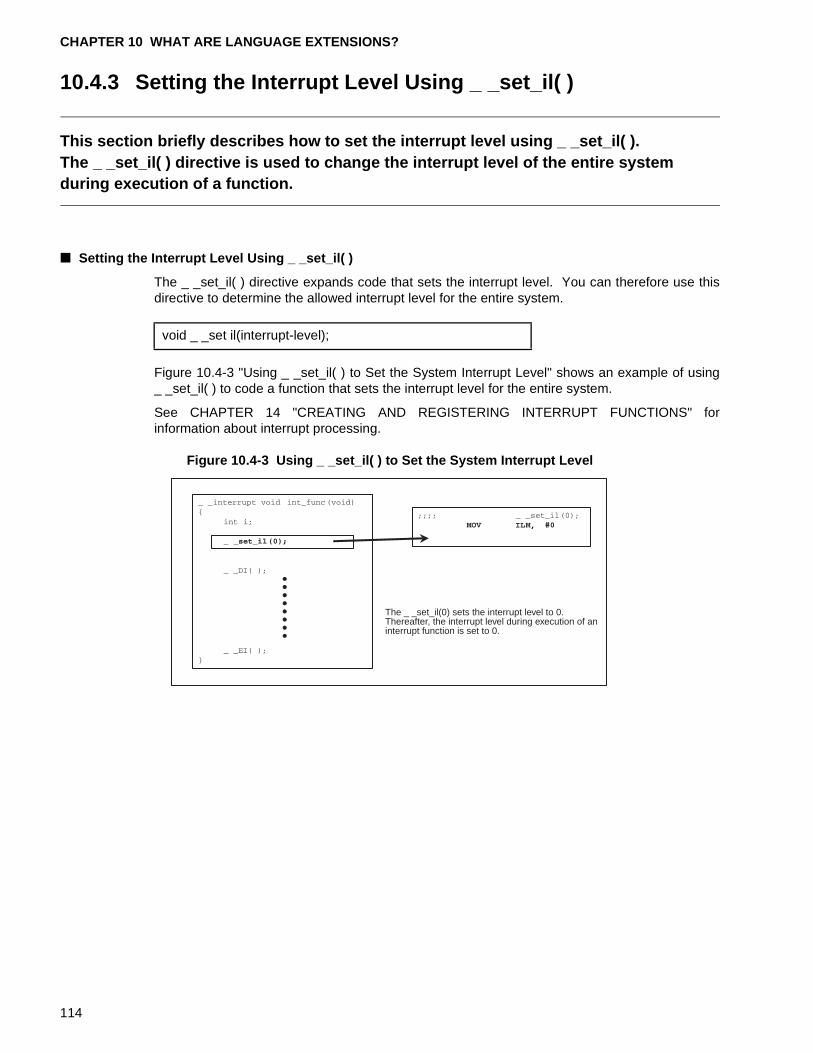
CHAPTER 10 WHAT ARE LANGUAGE EXTENSIONS?
10.4.3 Setting the Interrupt Level Using _ _set_il( )
This section briefly describes how to set the interrupt level using _ _set_il( ).The _ _set_il( ) directive is used to change the interrupt level of the entire system during execution of a function.
■ Setting the Interrupt Level Using _ _set_il( )
The _ _set_il( ) directive expands code that sets the interrupt level. You can therefore use thisdirective to determine the allowed interrupt level for the entire system.
Figure 10.4-3 "Using _ _set_il( ) to Set the System Interrupt Level" shows an example of using_ _set_il( ) to code a function that sets the interrupt level for the entire system.
See CHAPTER 14 "CREATING AND REGISTERING INTERRUPT FUNCTIONS" forinformation about interrupt processing.
Figure 10.4-3 Using _ _set_il( ) to Set the System Interrupt Level
void _ _set il(interrupt-level);
The _ _set_il(0) sets the interrupt level to 0.Thereafter, the interrupt level during execution of aninterrupt function is set to 0.
114
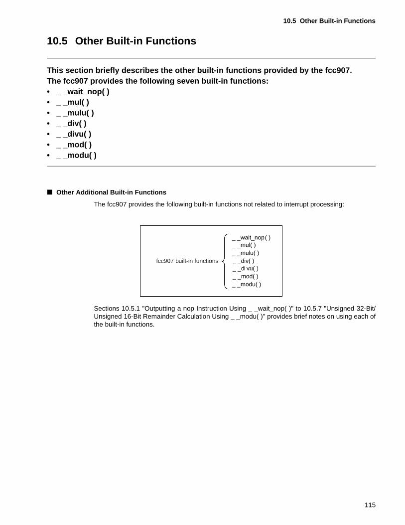
10.5 Other Built-in Functions
10.5 Other Built-in Functions
This section briefly describes the other built-in functions provided by the fcc907.The fcc907 provides the following seven built-in functions:• _ _wait_nop( )• _ _mul( ) • _ _mulu( ) • _ _div( ) • _ _divu( ) • _ _mod( ) • _ _modu( )
■ Other Additional Built-in Functions
The fcc907 provides the following built-in functions not related to interrupt processing:
Sections 10.5.1 "Outputting a nop Instruction Using _ _wait_nop( )" to 10.5.7 "Unsigned 32-Bit/Unsigned 16-Bit Remainder Calculation Using _ _modu( )" provides brief notes on using each ofthe built-in functions.
_ _wait_nop( )_ _mul( )_ _mulu( )_ _div( )_ _di vu( )_ _mod( )_ _modu( )
fcc907 built-in functions
115
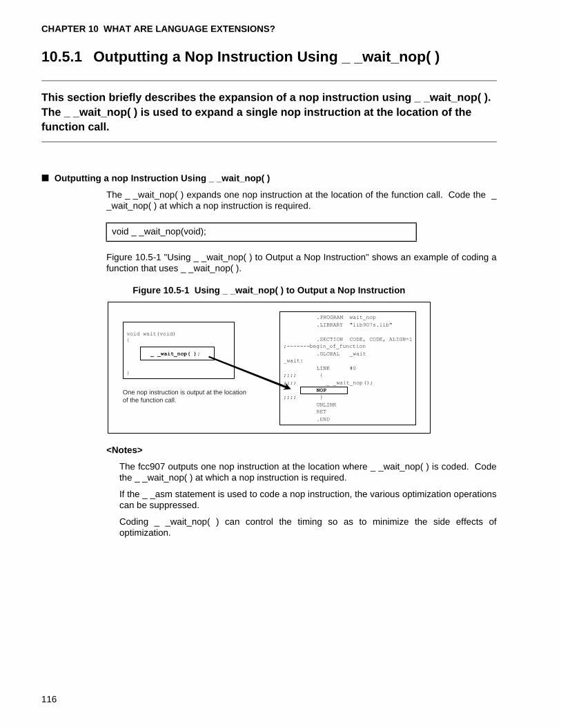
CHAPTER 10 WHAT ARE LANGUAGE EXTENSIONS?
10.5.1 Outputting a Nop Instruction Using _ _wait_nop( )
This section briefly describes the expansion of a nop instruction using _ _wait_nop( ).The _ _wait_nop( ) is used to expand a single nop instruction at the location of the function call.
■ Outputting a nop Instruction Using _ _wait_nop( )
The _ _wait_nop( ) expands one nop instruction at the location of the function call. Code the __wait_nop( ) at which a nop instruction is required.
Figure 10.5-1 "Using _ _wait_nop( ) to Output a Nop Instruction" shows an example of coding afunction that uses _ _wait_nop( ).
Figure 10.5-1 Using _ _wait_nop( ) to Output a Nop Instruction
<Notes>
The fcc907 outputs one nop instruction at the location where _ _wait_nop( ) is coded. Codethe _ _wait_nop( ) at which a nop instruction is required.
If the _ _asm statement is used to code a nop instruction, the various optimization operationscan be suppressed.
Coding _ _wait_nop( ) can control the timing so as to minimize the side effects ofoptimization.
void _ _wait_nop(void);
One nop instruction is output at the locationof the function call.
116
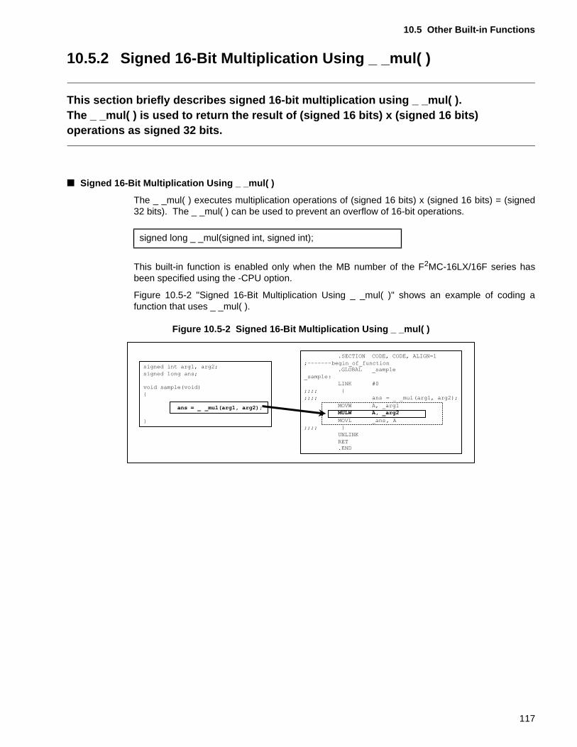
10.5 Other Built-in Functions
10.5.2 Signed 16-Bit Multiplication Using _ _mul( )
This section briefly describes signed 16-bit multiplication using _ _mul( ).The _ _mul( ) is used to return the result of (signed 16 bits) x (signed 16 bits) operations as signed 32 bits.
■ Signed 16-Bit Multiplication Using _ _mul( )
The _ _mul( ) executes multiplication operations of (signed 16 bits) x (signed 16 bits) = (signed32 bits). The _ _mul( ) can be used to prevent an overflow of 16-bit operations.
This built-in function is enabled only when the MB number of the F2MC-16LX/16F series hasbeen specified using the -CPU option.
Figure 10.5-2 "Signed 16-Bit Multiplication Using _ _mul( )" shows an example of coding afunction that uses _ _mul( ).
Figure 10.5-2 Signed 16-Bit Multiplication Using _ _mul( )
signed long _ _mul(signed int, signed int);
117
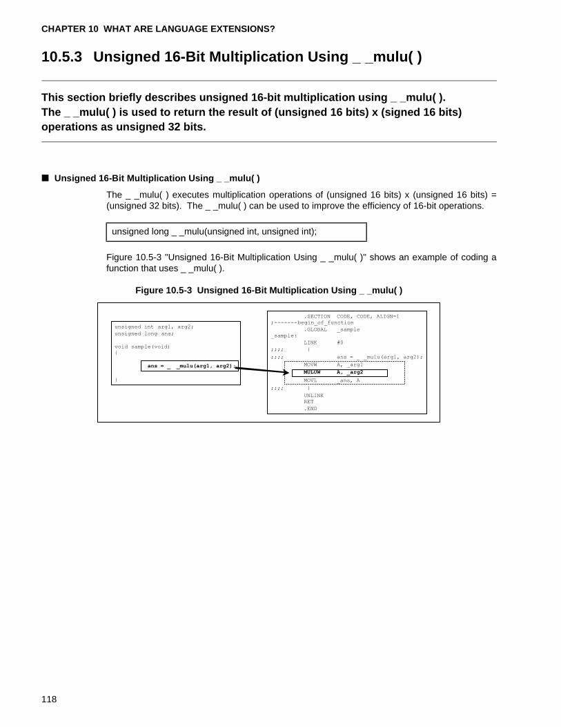
CHAPTER 10 WHAT ARE LANGUAGE EXTENSIONS?
10.5.3 Unsigned 16-Bit Multiplication Using _ _mulu( )
This section briefly describes unsigned 16-bit multiplication using _ _mulu( ).The _ _mulu( ) is used to return the result of (unsigned 16 bits) x (signed 16 bits) operations as unsigned 32 bits.
■ Unsigned 16-Bit Multiplication Using _ _mulu( )
The _ _mulu( ) executes multiplication operations of (unsigned 16 bits) x (unsigned 16 bits) =(unsigned 32 bits). The _ _mulu( ) can be used to improve the efficiency of 16-bit operations.
Figure 10.5-3 "Unsigned 16-Bit Multiplication Using _ _mulu( )" shows an example of coding afunction that uses _ _mulu( ).
Figure 10.5-3 Unsigned 16-Bit Multiplication Using _ _mulu( )
unsigned long _ _mulu(unsigned int, unsigned int);
118
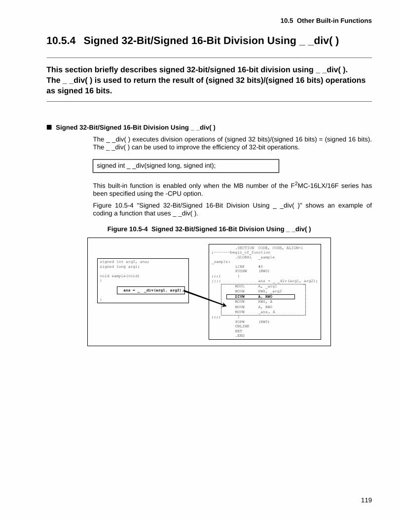
10.5 Other Built-in Functions
10.5.4 Signed 32-Bit/Signed 16-Bit Division Using _ _div( )
This section briefly describes signed 32-bit/signed 16-bit division using _ _div( ).The _ _div( ) is used to return the result of (signed 32 bits)/(signed 16 bits) operations as signed 16 bits.
■ Signed 32-Bit/Signed 16-Bit Division Using _ _div( )
The _ _div( ) executes division operations of (signed 32 bits)/(signed 16 bits) = (signed 16 bits).The _ _div( ) can be used to improve the efficiency of 32-bit operations.
This built-in function is enabled only when the MB number of the F2MC-16LX/16F series hasbeen specified using the -CPU option.
Figure 10.5-4 "Signed 32-Bit/Signed 16-Bit Division Using _ _div( )" shows an example ofcoding a function that uses _ _div( ).
Figure 10.5-4 Signed 32-Bit/Signed 16-Bit Division Using _ _div( )
signed int _ _div(signed long, signed int);
;;;;
119
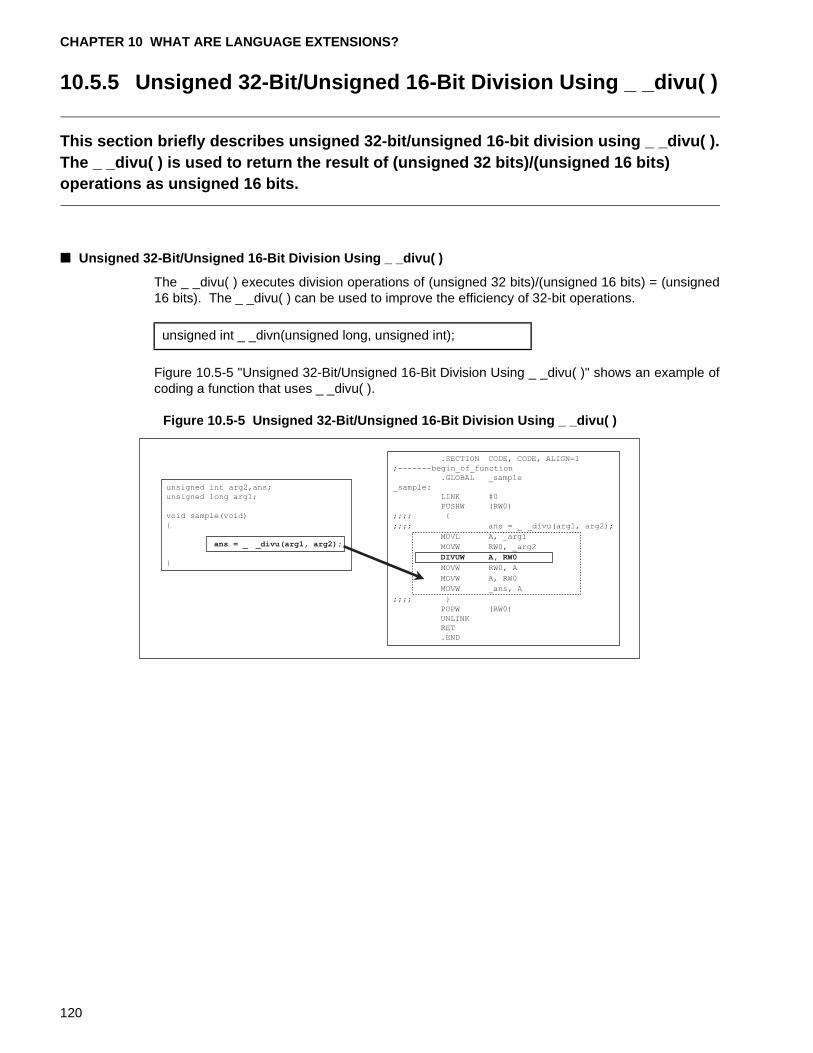
CHAPTER 10 WHAT ARE LANGUAGE EXTENSIONS?
10.5.5 Unsigned 32-Bit/Unsigned 16-Bit Division Using _ _divu( )
This section briefly describes unsigned 32-bit/unsigned 16-bit division using _ _divu( ).The _ _divu( ) is used to return the result of (unsigned 32 bits)/(unsigned 16 bits) operations as unsigned 16 bits.
■ Unsigned 32-Bit/Unsigned 16-Bit Division Using _ _divu( )
The _ _divu( ) executes division operations of (unsigned 32 bits)/(unsigned 16 bits) = (unsigned16 bits). The _ _divu( ) can be used to improve the efficiency of 32-bit operations.
Figure 10.5-5 "Unsigned 32-Bit/Unsigned 16-Bit Division Using _ _divu( )" shows an example ofcoding a function that uses _ _divu( ).
Figure 10.5-5 Unsigned 32-Bit/Unsigned 16-Bit Division Using _ _divu( )
unsigned int _ _divn(unsigned long, unsigned int);
unsigned int arg2,ans;
unsigned long arg1;
void sample(void)
{
ans = _ _divu(arg1, arg2);
}
.SECTION CODE, CODE, ALIGN=1
;-------begin_of_function
.GLOBAL _sample
_sample:
LINK #0
PUSHW (RW0)
;;;; {
;;;; ans = _ _divu(arg1, arg2);
MOVL A, _arg1
MOVW RW0, _arg2
DIVUW A, RW0
MOVW RW0, A
MOVW A, RW0
MOVW _ans, A
;;;; }
POPW (RW0)
UNLINK
RET
.END
120
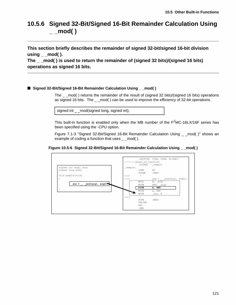
10.5 Other Built-in Functions
10.5.6 Signed 32-Bit/Signed 16-Bit Remainder Calculation Using _ _mod( )
This section briefly describes the remainder of signed 32-bit/signed 16-bit division using _ _mod( ).The _ _mod( ) is used to return the remainder of (signed 32 bits)/(signed 16 bits) operations as signed 16 bits.
■ Signed 32-Bit/Signed 16-Bit Remainder Calculation Using _ _mod( )
The _ _mod( ) returns the remainder of the result of (signed 32 bits)/(signed 16 bits) operationsas signed 16 bits. The _ _mod( ) can be used to improve the efficiency of 32-bit operations.
This built-in function is enabled only when the MB number of the F2MC-16LX/16F series hasbeen specified using the -CPU option.
Figure 7.1-3 "Signed 32-Bit/Signed 16-Bit Remainder Calculation Using _ _mod( )" shows anexample of coding a function that uses _ _mod( ).
Figure 10.5-6 Signed 32-Bit/Signed 16-Bit Remainder Calculation Using _ _mod( )
signed int _ _mod(signed long, signed int);
121
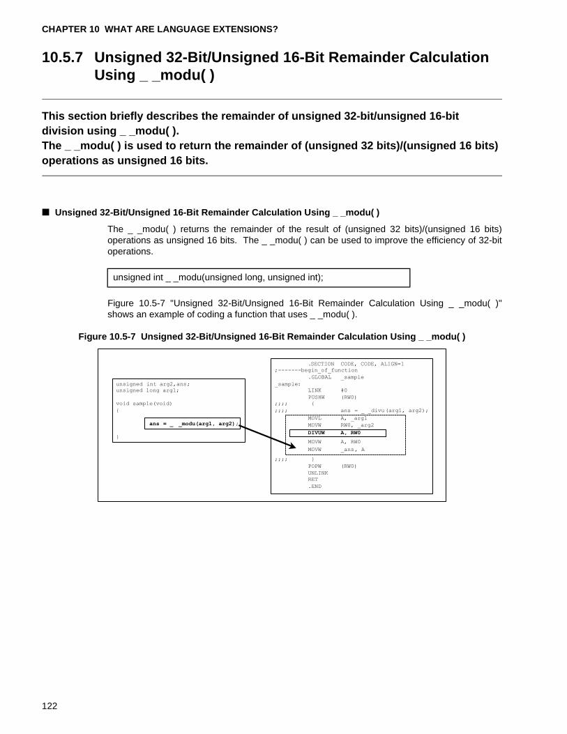
CHAPTER 10 WHAT ARE LANGUAGE EXTENSIONS?
10.5.7 Unsigned 32-Bit/Unsigned 16-Bit Remainder Calculation Using _ _modu( )
This section briefly describes the remainder of unsigned 32-bit/unsigned 16-bit division using _ _modu( ).The _ _modu( ) is used to return the remainder of (unsigned 32 bits)/(unsigned 16 bits) operations as unsigned 16 bits.
■ Unsigned 32-Bit/Unsigned 16-Bit Remainder Calculation Using _ _modu( )
The _ _modu( ) returns the remainder of the result of (unsigned 32 bits)/(unsigned 16 bits)operations as unsigned 16 bits. The _ _modu( ) can be used to improve the efficiency of 32-bitoperations.
Figure 10.5-7 "Unsigned 32-Bit/Unsigned 16-Bit Remainder Calculation Using _ _modu( )"shows an example of coding a function that uses _ _modu( ).
Figure 10.5-7 Unsigned 32-Bit/Unsigned 16-Bit Remainder Calculation Using _ _modu( )
unsigned int _ _modu(unsigned long, unsigned int);
122
CHAPTER 11 NOTES ON ASSEMBLER PROGRAM IN C PROGRAMS
This chapter provides notes on including Assembler program in C programs.
11.1 "Including Assembler Program in C Programs"
11.2 "Differences Between Using the _ _asm Statement and #pragma asm/endasm"
123
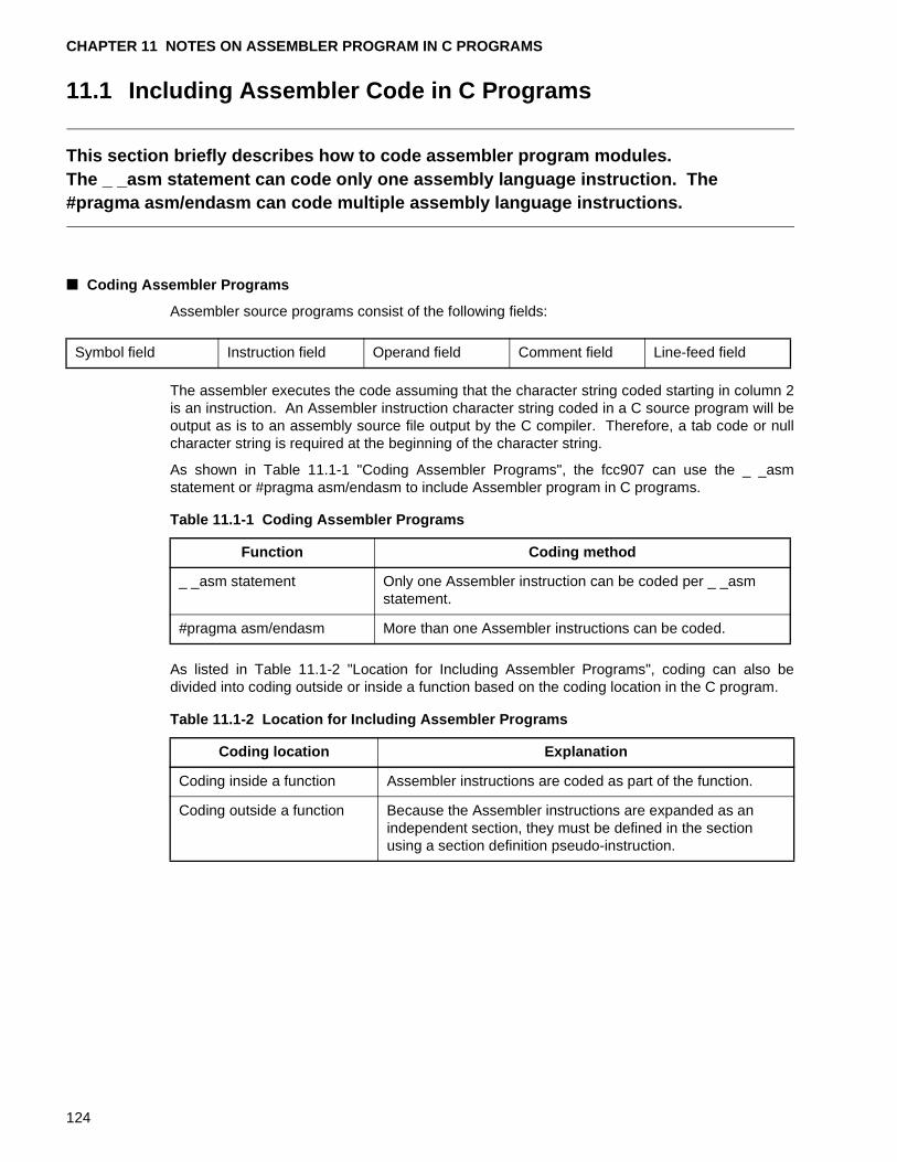
CHAPTER 11 NOTES ON ASSEMBLER PROGRAM IN C PROGRAMS
11.1 Including Assembler Code in C Programs
This section briefly describes how to code assembler program modules.The _ _asm statement can code only one assembly language instruction. The #pragma asm/endasm can code multiple assembly language instructions.
■ Coding Assembler Programs
Assembler source programs consist of the following fields:
The assembler executes the code assuming that the character string coded starting in column 2is an instruction. An Assembler instruction character string coded in a C source program will beoutput as is to an assembly source file output by the C compiler. Therefore, a tab code or nullcharacter string is required at the beginning of the character string.
As shown in Table 11.1-1 "Coding Assembler Programs", the fcc907 can use the _ _asmstatement or #pragma asm/endasm to include Assembler program in C programs.
As listed in Table 11.1-2 "Location for Including Assembler Programs", coding can also bedivided into coding outside or inside a function based on the coding location in the C program.
Symbol field Instruction field Operand field Comment field Line-feed field
Table 11.1-1 Coding Assembler Programs
Function Coding method
_ _asm statement Only one Assembler instruction can be coded per _ _asm statement.
#pragma asm/endasm More than one Assembler instructions can be coded.
Table 11.1-2 Location for Including Assembler Programs
Coding location Explanation
Coding inside a function Assembler instructions are coded as part of the function.
Coding outside a function Because the Assembler instructions are expanded as an independent section, they must be defined in the section using a section definition pseudo-instruction.
124
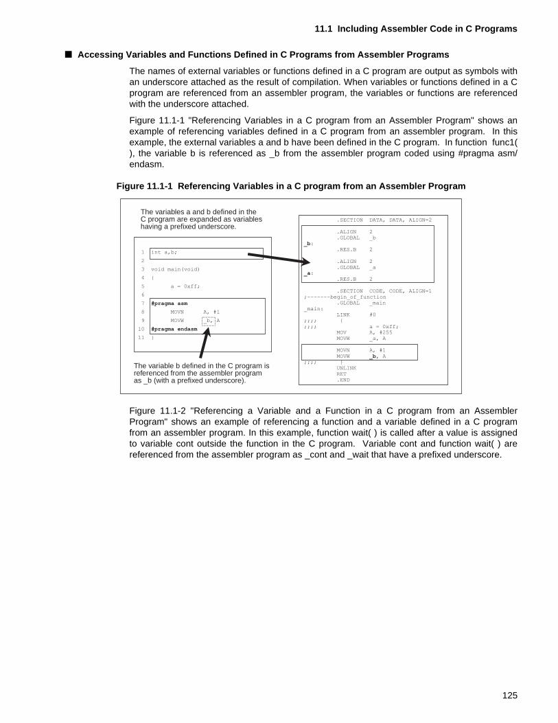
11.1 Including Assembler Code in C Programs
■ Accessing Variables and Functions Defined in C Programs from Assembler Programs
The names of external variables or functions defined in a C program are output as symbols withan underscore attached as the result of compilation. When variables or functions defined in a Cprogram are referenced from an assembler program, the variables or functions are referencedwith the underscore attached.
Figure 11.1-1 "Referencing Variables in a C program from an Assembler Program" shows anexample of referencing variables defined in a C program from an assembler program. In thisexample, the external variables a and b have been defined in the C program. In function func1(), the variable b is referenced as _b from the assembler program coded using #pragma asm/endasm.
Figure 11.1-1 Referencing Variables in a C program from an Assembler Program
Figure 11.1-2 "Referencing a Variable and a Function in a C program from an AssemblerProgram" shows an example of referencing a function and a variable defined in a C programfrom an assembler program. In this example, function wait( ) is called after a value is assignedto variable cont outside the function in the C program. Variable cont and function wait( ) arereferenced from the assembler program as _cont and _wait that have a prefixed underscore.
The variables a and b defined in theC program are expanded as variableshaving a prefixed underscore.
The variable b defined in the C program isreferenced from the assembler programas _b (with a prefixed underscore).
1 int a,b;
2
3 void main(void)
4 {
5 a = 0xff;
6
7 #pragma asm
8 MOVN A, #1
9 MOVW _b, A
10 #pragma endasm
11 }
.SECTION DATA, DATA, ALIGN=2
.ALIGN 2
.GLOBAL _b_b:
.RES.B 2
.ALIGN 2
.GLOBAL _a_a:
.RES.B 2
.SECTION CODE, CODE, ALIGN=1;-------begin_of_function
.GLOBAL _main_main:
LINK #0;;;; {;;;; a = 0xff;
MOV A, #255MOVW _a, A
MOVN A, #1MOVW _b, A
;;;; }UNLINKRET.END
125
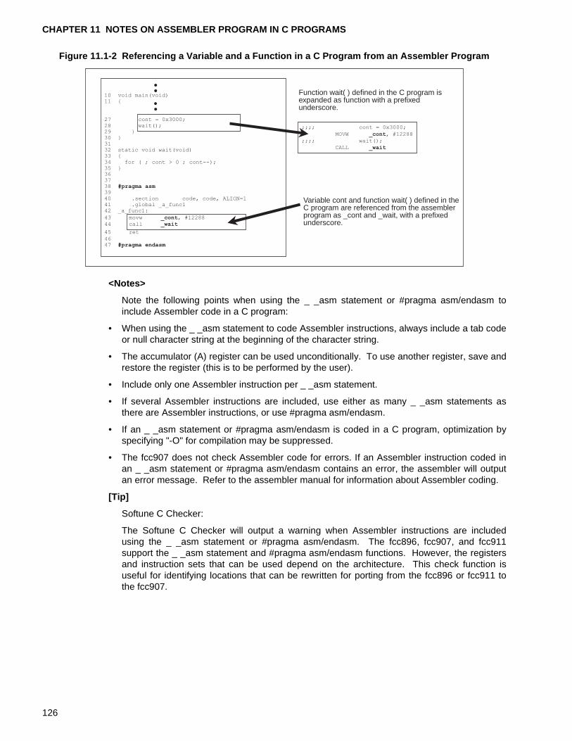
CHAPTER 11 NOTES ON ASSEMBLER PROGRAM IN C PROGRAMS
Figure 11.1-2 Referencing a Variable and a Function in a C Program from an Assembler Program
<Notes>
Note the following points when using the _ _asm statement or #pragma asm/endasm toinclude Assembler code in a C program:
• When using the _ _asm statement to code Assembler instructions, always include a tab codeor null character string at the beginning of the character string.
• The accumulator (A) register can be used unconditionally. To use another register, save andrestore the register (this is to be performed by the user).
• Include only one Assembler instruction per _ _asm statement.
• If several Assembler instructions are included, use either as many _ _asm statements asthere are Assembler instructions, or use #pragma asm/endasm.
• If an _ _asm statement or #pragma asm/endasm is coded in a C program, optimization byspecifying "-O" for compilation may be suppressed.
• The fcc907 does not check Assembler code for errors. If an Assembler instruction coded inan _ _asm statement or #pragma asm/endasm contains an error, the assembler will outputan error message. Refer to the assembler manual for information about Assembler coding.
[Tip]
Softune C Checker:
The Softune C Checker will output a warning when Assembler instructions are includedusing the _ _asm statement or #pragma asm/endasm. The fcc896, fcc907, and fcc911support the _ _asm statement and #pragma asm/endasm functions. However, the registersand instruction sets that can be used depend on the architecture. This check function isuseful for identifying locations that can be rewritten for porting from the fcc896 or fcc911 tothe fcc907.
Function wait( ) defined in the C program isexpanded as function with a prefixedunderscore.
Variable cont and function wait( ) defined in theC program are referenced from the assemblerprogram as _cont and _wait, with a prefixedunderscore.
;;;; cont = 0x3000;
MOVW _cont, #12288
;;;; wait();
CALL _wait
10 void main(void)11 {
27 cont = 0x3000;28 wait();29 }30 }3132 static void wait(void)33 {34 for ( ; cont > 0 ; cont--);35 }363738 #pragma asm3940 .section code, code, ALIGN=141 .global _a_func142 _a_func1:
43 movw _cont, #1228844 call _wait
45 ret
4647 #pragma endasm
126
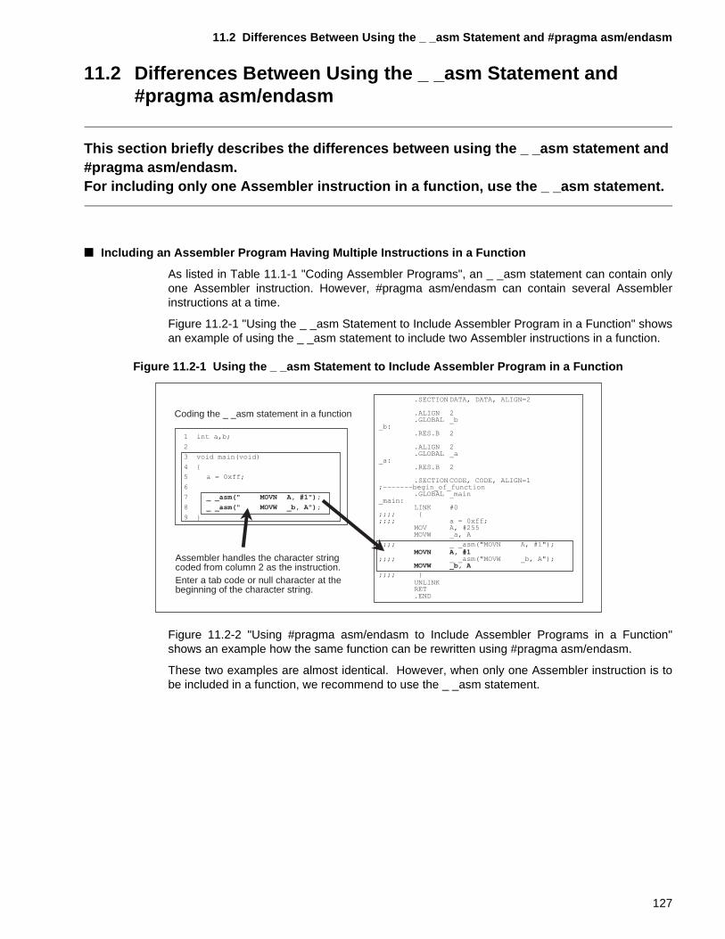
11.2 Differences Between Using the _ _asm Statement and #pragma asm/endasm
11.2 Differences Between Using the _ _asm Statement and #pragma asm/endasm
This section briefly describes the differences between using the _ _asm statement and #pragma asm/endasm.For including only one Assembler instruction in a function, use the _ _asm statement.
■ Including an Assembler Program Having Multiple Instructions in a Function
As listed in Table 11.1-1 "Coding Assembler Programs", an _ _asm statement can contain onlyone Assembler instruction. However, #pragma asm/endasm can contain several Assemblerinstructions at a time.
Figure 11.2-1 "Using the _ _asm Statement to Include Assembler Program in a Function" showsan example of using the _ _asm statement to include two Assembler instructions in a function.
Figure 11.2-1 Using the _ _asm Statement to Include Assembler Program in a Function
Figure 11.2-2 "Using #pragma asm/endasm to Include Assembler Programs in a Function"shows an example how the same function can be rewritten using #pragma asm/endasm.
These two examples are almost identical. However, when only one Assembler instruction is tobe included in a function, we recommend to use the _ _asm statement.
Coding the _ _asm statement in a function
Assembler handles the character string coded from column 2 as the instruction. Enter a tab code or null character at the beginning of the character string.
1 int a,b;
2
3 void main(void)
4 {
5 a = 0xff;
6
7 _ _asm(" MOVN A, #1");
8 _ _asm(" MOVW _b, A");
9 }
.SECTION DATA, DATA, ALIGN=2
.ALIGN 2
.GLOBAL _b_b:
.RES.B 2
.ALIGN 2
.GLOBAL _a_a:
.RES.B 2
.SECTION CODE, CODE, ALIGN=1;-------begin_of_function
.GLOBAL _main_main:
LINK #0;;;; {;;;; a = 0xff;
MOV A, #255MOVW _a, A
;;;; _ _asm("MOVN A, #1");MOVN A, #1
;;;; _ _asm("MOVW _b, A");MOVW _b, A
;;;; }UNLINKRET.END
127
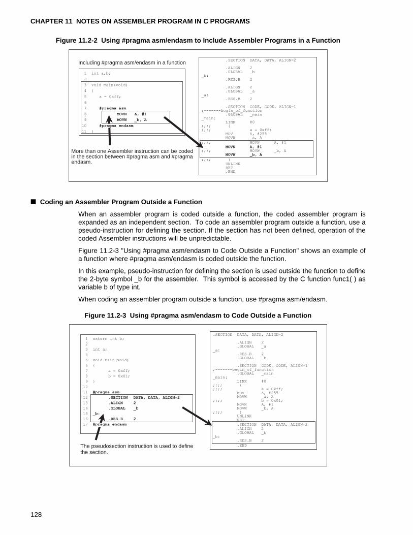
CHAPTER 11 NOTES ON ASSEMBLER PROGRAM IN C PROGRAMS
Figure 11.2-2 Using #pragma asm/endasm to Include Assembler Programs in a Function
■ Coding an Assembler Program Outside a Function
When an assembler program is coded outside a function, the coded assembler program isexpanded as an independent section. To code an assembler program outside a function, use apseudo-instruction for defining the section. If the section has not been defined, operation of thecoded Assembler instructions will be unpredictable.
Figure 11.2-3 "Using #pragma asm/endasm to Code Outside a Function" shows an example ofa function where #pragma asm/endasm is coded outside the function.
In this example, pseudo-instruction for defining the section is used outside the function to definethe 2-byte symbol _b for the assembler. This symbol is accessed by the C function func1( ) asvariable b of type int.
When coding an assembler program outside a function, use #pragma asm/endasm.
Figure 11.2-3 Using #pragma asm/endasm to Code Outside a Function
Including #pragma asm/endasm in a function
More than one Assembler instruction can be codedin the section between #pragma asm and #pragmaendasm.
1 int a,b;
2
3 void main(void)
4 {
5 a = 0xff;
6
7 #pragma asm
8 MOVN A, #1
9 MOVW _b, A
10 #
11 }
.SECTION DATA, DATA, ALIGN=2
.ALIGN 2
.GLOBAL _b_b:
.RES.B 2
.ALIGN 2
.GLOBAL _a_a:
.RES.B 2
.SECTION CODE, CODE, ALIGN=1;-------begin_of_function
.GLOBAL _main_main:
LINK #0;;;; {;;;; a = 0xff;
MOV A, #255MOVW _a, A
;;;; MOVN A, #1MOVN A, #1
;;;; MOVW _b, AMOVW _b, A
;;;; }UNLINKRET.END
pragma endasm
The pseudosection instruction is used to definethe section.
1 extern int b;
2
3 int a;
4
5 void main(void)
6 {
7 a = 0xff;
8 b = 0x01;
9 }
10
11 #pragma asm
12 .SECTION DATA, DATA, ALIGN=2
13 .ALIGN 2
14 .GLOBAL _b
15 _b:
16 .RES.B 2
17 #
.SECTION DATA, DATA, ALIGN=2
.ALIGN 2
.GLOBAL _a_a:
.RES.B 2
.GLOBAL _b
.SECTION CODE, CODE, ALIGN=1;-------begin_of_function
.GLOBAL _main_main:
LINK #0;;;; {;;;; a = 0xff;
MOV A, #255MOVW _a, A
;;;; b = 0x01;MOVN A, #1MOVW _b, A
;;;; }UNLINKRET.SECTION DATA, DATA, ALIGN=2.ALIGN 2.GLOBAL _b
_b:.RES.B 2
.END
pragma endasm
128
11.2 Differences Between Using the _ _asm Statement and #pragma asm/endasm
[Tip]
Softune C Checker:
The Softune C Checker will output a warning when Assembler instructions are coded using
_ _asm statement or #pragma asm/endasm. The fcc896, fcc907, and fcc911 support the
_ _asm statement and #pragma asm/endasm. However, the registers and instruction setsthat can be used depend on the architecture. This check function is useful for identifyinglocations that can be rewritten from the fcc896 or fcc911 to the fcc907.
129

CHAPTER 11 NOTES ON ASSEMBLER PROGRAM IN C PROGRAMS
130
CHAPTER 12 NOTES ON DEFINING AND ACCESSING THE I/O AREA
This chapter describes the definition and accessing of resources mapped into the I/O area. The chapter uses as examples the I/O area of the MB90678 series of
microcontrollers, which belong to the F 2MC-16 family of microcontrollers, to explain how resources mapped into the I/O area are defined and accessed.
12.1 "M90678 Series I/O Areas"
12.2 "Defining and Accessing Variables Mapped into the I/O Areas"
131
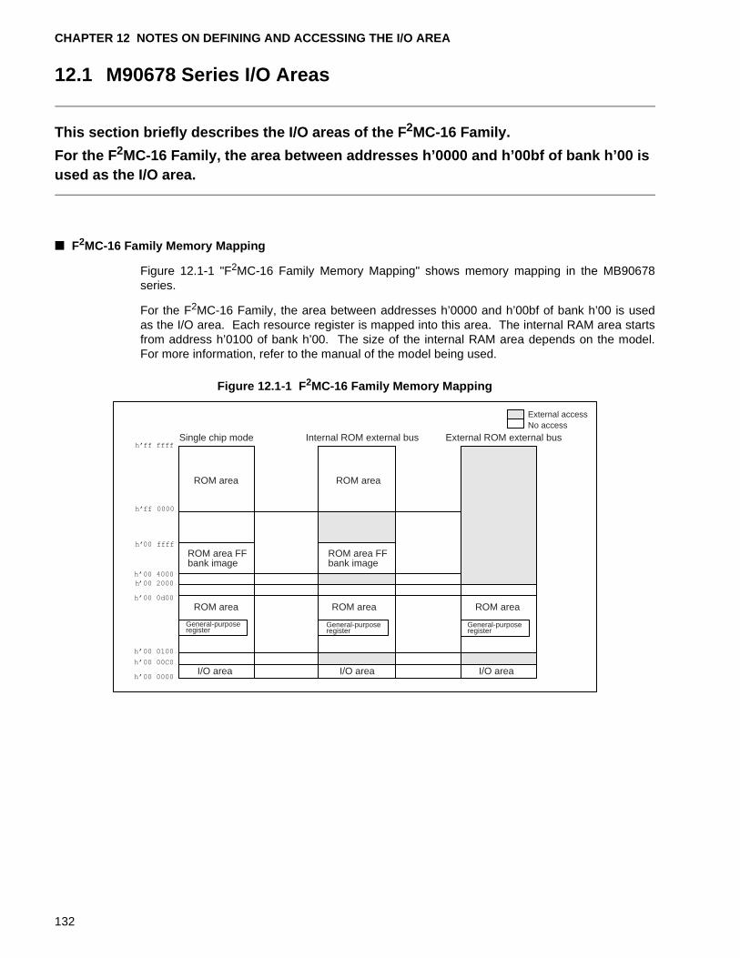
CHAPTER 12 NOTES ON DEFINING AND ACCESSING THE I/O AREA
12.1 M90678 Series I/O Areas
This section briefly describes the I/O areas of the F 2MC-16 Family.
For the F 2MC-16 Family, the area between addresses h’0000 and h’00bf of bank h’00 is used as the I/O area.
■ F2MC-16 Family Memory Mapping
Figure 12.1-1 "F2MC-16 Family Memory Mapping" shows memory mapping in the MB90678series.
For the F2MC-16 Family, the area between addresses h’0000 and h’00bf of bank h’00 is usedas the I/O area. Each resource register is mapped into this area. The internal RAM area startsfrom address h’0100 of bank h’00. The size of the internal RAM area depends on the model.For more information, refer to the manual of the model being used.
Figure 12.1-1 F 2MC-16 Family Memory Mapping
ROM area FF bank image
ROM area FF bank image
ROM area ROM area
ROM area ROM area ROM area
Single chip mode Internal ROM external bus External ROM external bus
General-purpose register
General-purpose register
General-purpose register
I/O area I/O area I/O area
External access No access
132
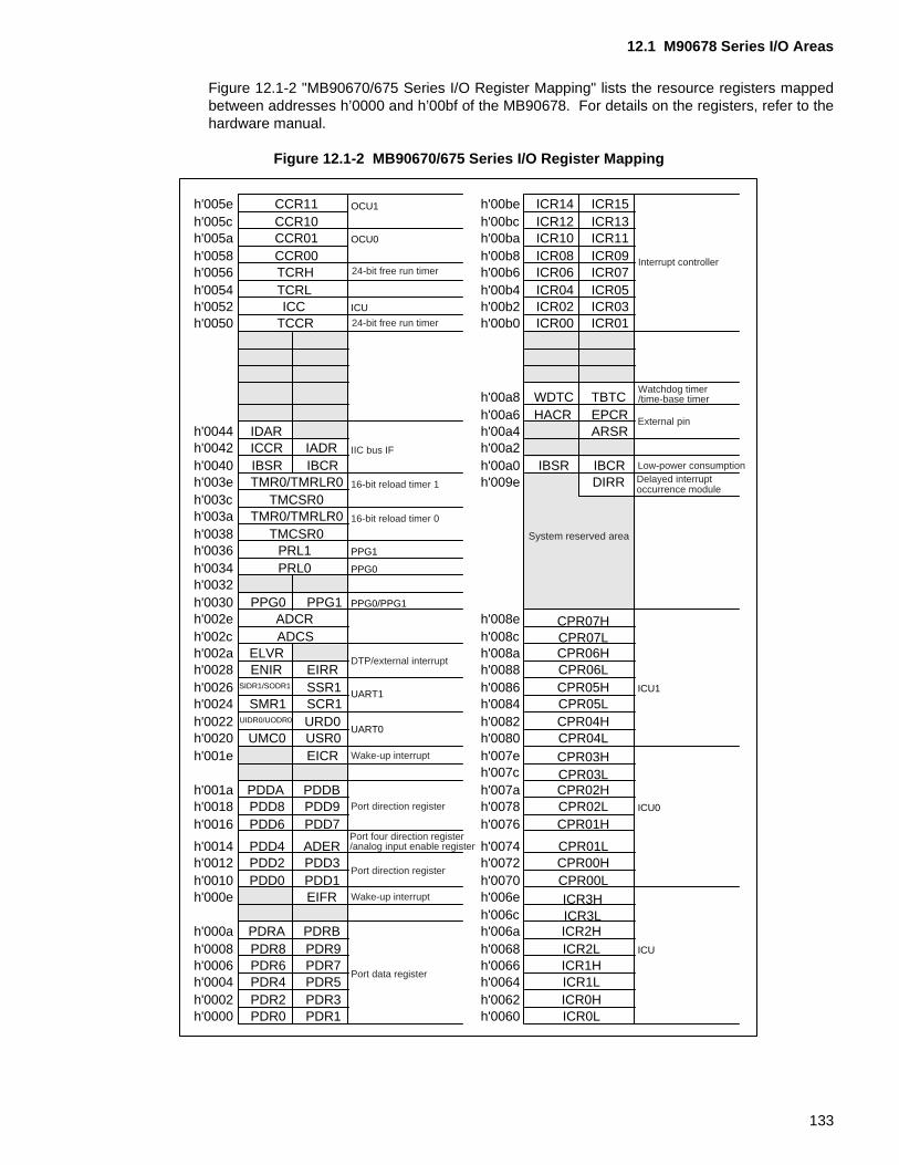
12.1 M90678 Series I/O Areas
Figure 12.1-2 "MB90670/675 Series I/O Register Mapping" lists the resource registers mappedbetween addresses h’0000 and h’00bf of the MB90678. For details on the registers, refer to thehardware manual.
Figure 12.1-2 MB90670/675 Series I/O Register Mapping
h'005e OCU1 h'00be ICR14 ICR15h'005c h'00bc ICR12 ICR13h'005a OCU0 h'00ba ICR10 ICR11h'0058 h'00b8 ICR08 ICR09h'0056 h'00b6 ICR06 ICR07h'0054 h'00b4 ICR04 ICR05h'0052 ICU h'00b2 ICR02 ICR03h'0050 h'00b0 ICR00 ICR01
h'00a8 WDTC TBTCh'00a6 HACR EPCR External pin
h'0044 IDAR h'00a4 ARSRh'0042 ICCR IADR IIC bus IF h'00a2h'0040 IBSR IBCR h'00a0 IBSR IBCR Low-power consumption
h'003e 16-bit reload timer 1 h'009e DIRR Delayed interrupt occurrence module
h'003ch'003a 16-bit reload timer 0
h'0038h'0036 PPG1
h'0034 PPG0
h'0032h'0030 PPG0 PPG1 PPG0/PPG1
h'002e h'008eh'002c h'008ch'002a ELVR
DTP/external interrupt h'008a
h'0028 ENIR EIRR h'0088h'0026 SIDR1/SODR1 SSR1 UART1 h'0086 ICU1
h'0024 SMR1 SCR1 h'0084h'0022 UIDR0/UODR0 URD0
UART0h'0082
h'0020 UMC0 USR0 h'0080h'001e EICR Wake-up interrupt h'007e
h'007ch'001a PDDA PDDB h'007ah'0018 PDD8 PDD9 Port direction register h'0078 ICU0
h'0016 PDD6 PDD7 h'0076
h'0014 PDD4 ADERPort four direction register/analog input enable register h'0074
h'0012 PDD2 PDD3Port direction register
h'0072h'0010 PDD0 PDD1 h'0070h'000e EIFR Wake-up interrupt h'006e
h'006ch'000a PDRA PDRB h'006ah'0008 PDR8 PDR9 h'0068 ICU
h'0006 PDR6 PDR7Port data register
h'0066h'0004 PDR4 PDR5 h'0064h'0002 PDR2 PDR3 h'0062h'0000 PDR0 PDR1 h'0060
CPR04HCPR04L
CPR06HCPR06LCPR05HCPR05L
CPR02LCPR02HCPR03LCPR03H
CPR00LCPR00HCPR01L
CPR01H
CPR07HCPR07L
ICR0LICR0HICR1LICR1HICR2LICR2HICR3LICR3H
System reserved area
CCR10CCR11
TCRLTCRHCCR00CCR01
TMR0/TMRLR0TMCSR0
TCCRICC
ADCSADCR
TMR0/TMRLR0TMCSR0
PRL1PRL0
24-bit free run timerInterrupt controller
24-bit free run timer
Watchdog timer/time-base timer
133
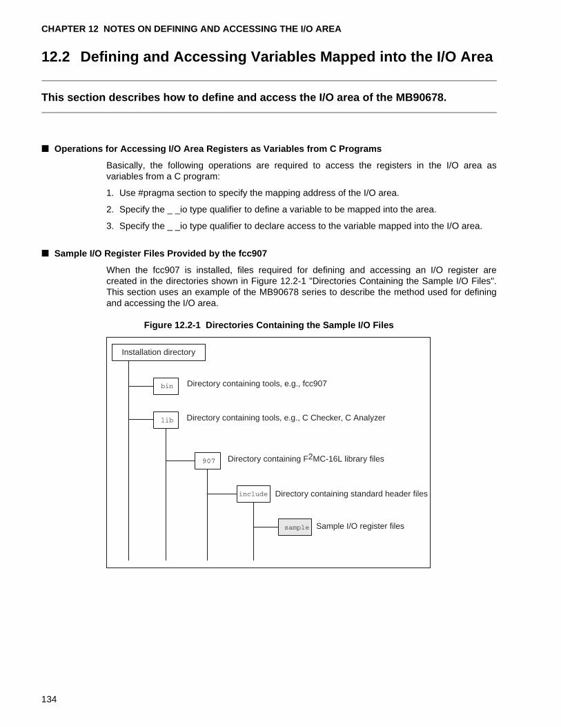
CHAPTER 12 NOTES ON DEFINING AND ACCESSING THE I/O AREA
12.2 Defining and Accessing Variables Mapped into the I/O Area
This section describes how to define and access the I/O area of the MB90678.
■ Operations for Accessing I/O Area Registers as Variables from C Programs
Basically, the following operations are required to access the registers in the I/O area asvariables from a C program:
1. Use #pragma section to specify the mapping address of the I/O area.
2. Specify the _ _io type qualifier to define a variable to be mapped into the area.
3. Specify the _ _io type qualifier to declare access to the variable mapped into the I/O area.
■ Sample I/O Register Files Provided by the fcc907
When the fcc907 is installed, files required for defining and accessing an I/O register arecreated in the directories shown in Figure 12.2-1 "Directories Containing the Sample I/O Files".This section uses an example of the MB90678 series to describe the method used for definingand accessing the I/O area.
Figure 12.2-1 Directories Containing the Sample I/O Files
Installation directory
Directory containing tools, e.g., fcc907
Directory containing tools, e.g., C Checker, C Analyzer
Directory containing F2MC-16L library files
Directory containing standard header files
Sample I/O register files
134
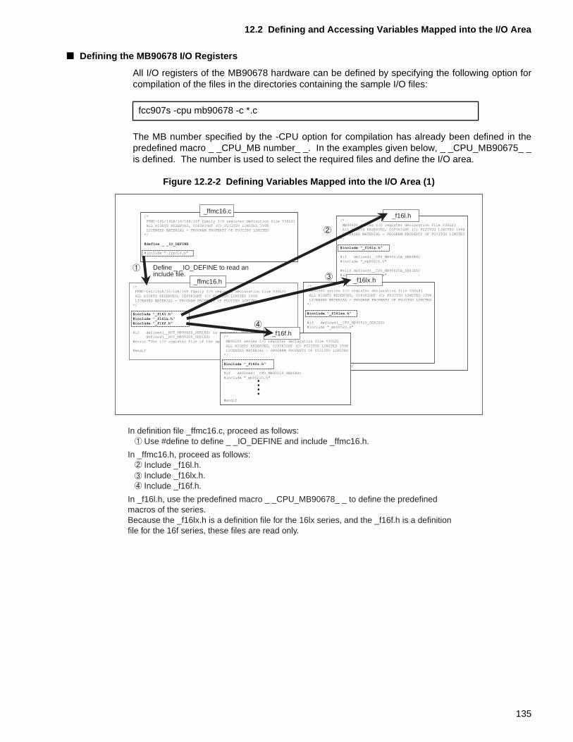
12.2 Defining and Accessing Variables Mapped into the I/O Area
■ Defining the MB90678 I/O Registers
All I/O registers of the MB90678 hardware can be defined by specifying the following option forcompilation of the files in the directories containing the sample I/O files:
The MB number specified by the -CPU option for compilation has already been defined in thepredefined macro _ _CPU_MB number_ _. In the examples given below, _ _CPU_MB90675_ _is defined. The number is used to select the required files and define the I/O area.
Figure 12.2-2 Defining Variables Mapped into the I/O Area (1)
fcc907s -cpu mb90678 -c *.c
In definition file _ffmc16.c, proceed as follows: Use #define to define _ _IO_DEFINE and include _ffmc16.h.
In _ffmc16.h, proceed as follows: Include _f16l.h. Include _f16lx.h. Include _f16f.h.
In _f16l.h, use the predefined macro _ _CPU_MB90678_ _ to define the predefined macros of the series. Because the _f16lx.h is a definition file for the 16lx series, and the _f16f.h is a definition file for the 16f series, these files are read only.
Define _ _IO_DEFINE to read an include file.
/*
FFMC-16L/16LX/16/16H/16F family I/O register definition file V30L01ALL RIGHTS RESERVED, COPYRIGHT (C) FUJITSU LIMITED 1998
LICENSED MATERIAL - PROGRAM PROPERTY OF FUJITSU LIMITED
*/
#define _ _IO_DEFINE
#include "_ffmc16.h"
/*FFMC-16L/16LX/16/16H/16F family I/O register declaration file V30L01
ALL RIGHTS RESERVED, COPYRIGHT (C) FUJITSU LIMITED 1998
LICENSED MATERIAL - PROGRAM PROPERTY OF FUJITSU LIMITED*/
#include "_f16l.h"
#include "_f16lx.h"#include "_f16f.h"
#if defined(__NOT_MB90600_SERIES) && defined(__NOT_MB90500_SERIES) && ¥defined(__NOT_MB90200_SERIES)
#error "The I/O register file of the specified CPU option does not exist"
#endif
_ffmc16.h
_ffmc16.c/*
MB90600 series I/O register declaration file V30L01
ALL RIGHTS RESERVED, COPYRIGHT (C) FUJITSU LIMITED 1998LICENSED MATERIAL - PROGRAM PROPERTY OF FUJITSU LIMITED
*/
#include "_f16ls.h"
#if defined(__CPU_MB90610A_SERIES)
#include "_mb90610.h"
#elif defined(__CPU_MB90620A_SERIES)
#include "_mb90620.h"
#elif defined(__CPU_MB90630A_SERIES)
#include "_mb90630.h"
#elif defined(__CPU_MB90640A_SERIES)
#include "_mb90640.h"
#elif defined(__CPU_MB90650A_SERIES)
#include "_mb90650.h"
#elif defined(__CPU_MB90660A_SERIES)
#include "_mb90660.h"
#elif defined(__CPU_MB90670_SERIES)
#include "_mb90670.h"
#elif defined(__CPU_MB90675_SERIES)
#include "_mb90675.h"
#endif
_f16l.h
/*MB90500 series I/O register declaration file V30L01
ALL RIGHTS RESERVED, COPYRIGHT (C) FUJITSU LIMITED 1998
LICENSED MATERIAL - PROGRAM PROPERTY OF FUJITSU LIMITED
*/
#include "_f16lxs.h"
#if defined(__CPU_MB90520_SERIES)
#include "_mb90520.h"
#endif
_f16lx.h
/*
MB90200 series I/O register declaration file V30L01
ALL RIGHTS RESERVED, COPYRIGHT (C) FUJITSU LIMITED 1998LICENSED MATERIAL - PROGRAM PROPERTY OF FUJITSU LIMITED
*/
#include "_f16fs.h"
#if defined(__CPU_MB90210_SERIES)
#include "_mb90210.h"
#endif
_f16f.h
135
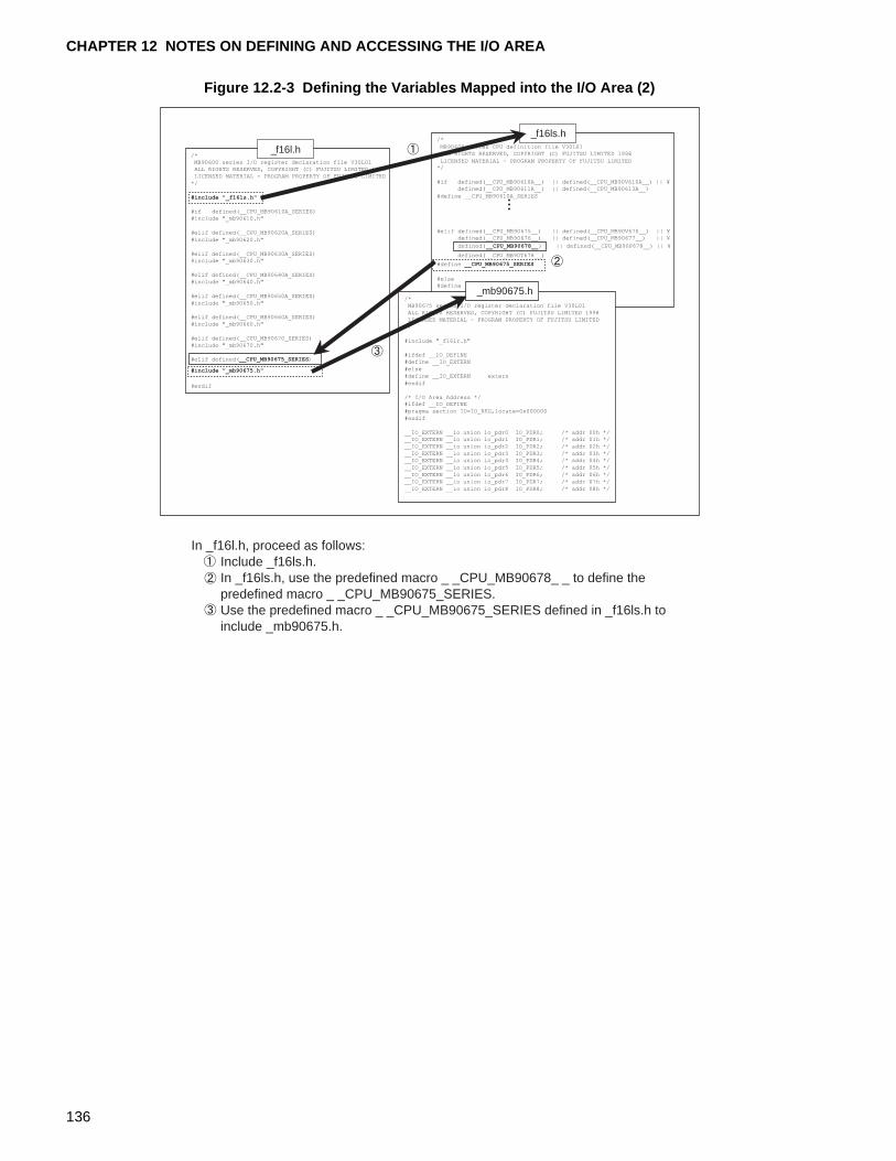
CHAPTER 12 NOTES ON DEFINING AND ACCESSING THE I/O AREA
Figure 12.2-3 Defining the Variables Mapped into the I/O Area (2)
In _f16l.h, proceed as follows: Include _f16ls.h. In _f16ls.h, use the predefined macro _ _CPU_MB90678_ _ to define the predefined macro _ _CPU_MB90675_SERIES. Use the predefined macro _ _CPU_MB90675_SERIES defined in _f16ls.h to include _mb90675.h.
/*MB90600 series I/O register declaration file V30L01ALL RIGHTS RESERVED, COPYRIGHT (C) FUJITSU LIMITED 1998
LICENSED MATERIAL - PROGRAM PROPERTY OF FUJITSU LIMITED
*/
#include "_f16ls.h"
#if defined(__CPU_MB90610A_SERIES)
#include "_mb90610.h"
#elif defined(__CPU_MB90620A_SERIES)
#include "_mb90620.h"
#elif defined(__CPU_MB90630A_SERIES)#include "_mb90630.h"
#elif defined(__CPU_MB90640A_SERIES)#include "_mb90640.h"
#elif defined(__CPU_MB90650A_SERIES)
#include "_mb90650.h"
#elif defined(__CPU_MB90660A_SERIES)
#include "_mb90660.h"
#elif defined(__CPU_MB90670_SERIES)
#include "_mb90670.h"
#elif defined(__CPU_MB90675_SERIES)
#include "_mb90675.h"
#endif
_f16l.h/*
MB90600 series CPU definition file V30L01ALL RIGHTS RESERVED, COPYRIGHT (C) FUJITSU LIMITED 1998
LICENSED MATERIAL - PROGRAM PROPERTY OF FUJITSU LIMITED*/
#if defined(__CPU_MB90610A__) || defined(__CPU_MB90V610A__) || ¥defined(__CPU_MB90611A__) || defined(__CPU_MB90613A__)
#define __CPU_MB90610A_SERIES
#elif defined(__CPU_MB90675__) || defined(__CPU_MB90V670__) || ¥defined(__CPU_MB90676__) || defined(__CPU_MB90677__) || ¥
defined(__CPU_MB90678__)
defined(__CPU_MB90T678__)
#define __CPU_MB90675_SERIES
#else#define __NOT_MB90600_SERIES
#endif
_f16ls.h
/*MB90675 series I/O register declaration file V30L01
ALL RIGHTS RESERVED, COPYRIGHT (C) FUJITSU LIMITED 1998
LICENSED MATERIAL - PROGRAM PROPERTY OF FUJITSU LIMITED
*/
#include "_f16lr.h"
#ifdef __IO_DEFINE
#define __IO_EXTERN
#else
#define __IO_EXTERN extern
#endif
/* I/O Area Address */#ifdef __IO_DEFINE
#pragma section IO=IO_REG,locate=0x000000
#endif
__IO_EXTERN __io union io_pdr0 IO_PDR0; /* addr 00h */__IO_EXTERN __io union io_pdr1 IO_PDR1; /* addr 01h */
__IO_EXTERN __io union io_pdr2 IO_PDR2; /* addr 02h */
__IO_EXTERN __io union io_pdr3 IO_PDR3; /* addr 03h */__IO_EXTERN __io union io_pdr4 IO_PDR4; /* addr 04h */
__IO_EXTERN __io union io_pdr5 IO_PDR5; /* addr 05h */
__IO_EXTERN __io union io_pdr6 IO_PDR6; /* addr 06h */
__IO_EXTERN __io union io_pdr7 IO_PDR7; /* addr 07h */
__IO_EXTERN __io union io_pdr8 IO_PDR8; /* addr 08h */
_mb90675.h
|| defined(__CPU_MB90P678__) || ¥
136
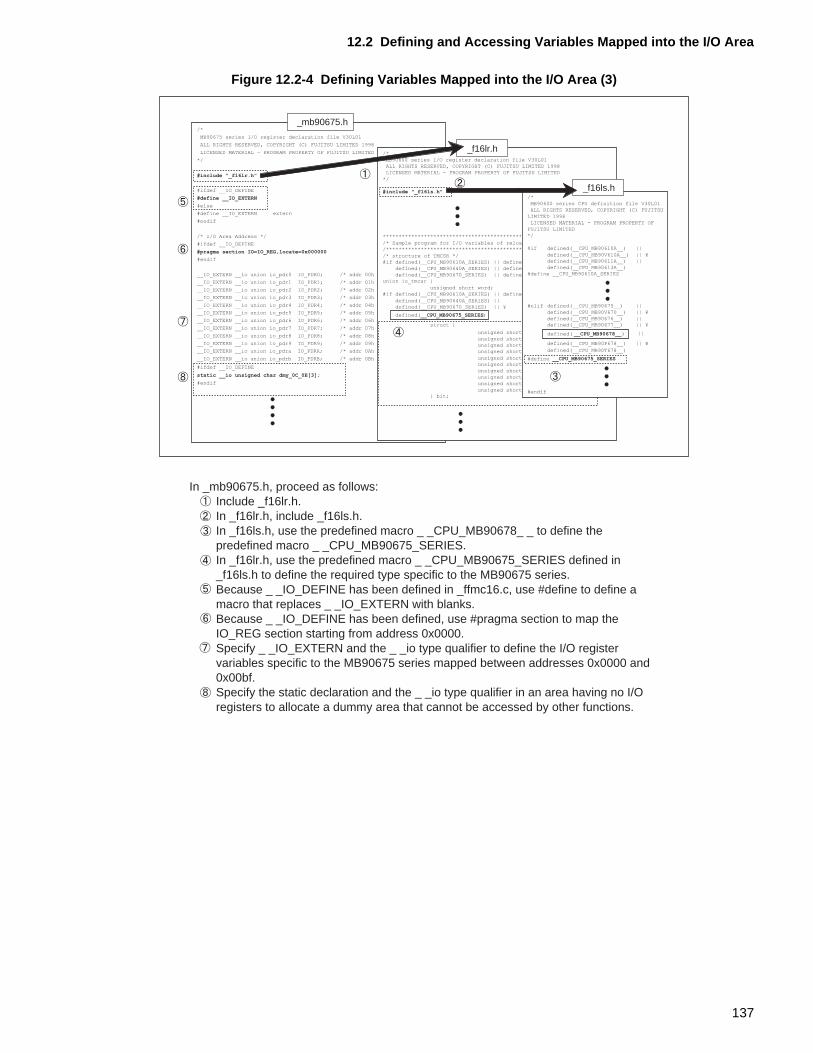
12.2 Defining and Accessing Variables Mapped into the I/O Area
Figure 12.2-4 Defining Variables Mapped into the I/O Area (3)
In _mb90675.h, proceed as follows: Include _f16lr.h. In _f16lr.h, include _f16ls.h. In _f16ls.h, use the predefined macro _ _CPU_MB90678_ _ to define the predefined macro _ _CPU_MB90675_SERIES. In _f16lr.h, use the predefined macro _ _CPU_MB90675_SERIES defined in _f16ls.h to define the required type specific to the MB90675 series. Because _ _IO_DEFINE has been defined in _ffmc16.c, use #define to define a macro that replaces _ _IO_EXTERN with blanks. Because _ _IO_DEFINE has been defined, use #pragma section to map the IO_REG section starting from address 0x0000. Specify _ _IO_EXTERN and the _ _io type qualifier to define the I/O register variables specific to the MB90675 series mapped between addresses 0x0000 and 0x00bf. Specify the static declaration and the _ _io type qualifier in an area having no I/O registers to allocate a dummy area that cannot be accessed by other functions.
/*
MB90675 series I/O register declaration file V30L01
ALL RIGHTS RESERVED, COPYRIGHT (C) FUJITSU LIMITED 1998
LICENSED MATERIAL - PROGRAM PROPERTY OF FUJITSU LIMITED
*/
#include "_f16lr.h"
#ifdef __IO_DEFINE
#define __IO_EXTERN
#else
#define __IO_EXTERN extern
#endif
/* I/O Area Address */
#ifdef __IO_DEFINE
#pragma section IO=IO_REG,locate=0x000000
#endif
__IO_EXTERN __io union io_pdr0 IO_PDR0; /* addr 00h */
__IO_EXTERN __io union io_pdr1 IO_PDR1; /* addr 01h */
__IO_EXTERN __io union io_pdr2 IO_PDR2; /* addr 02h */
__IO_EXTERN __io union io_pdr3 IO_PDR3; /* addr 03h */
__IO_EXTERN __io union io_pdr4 IO_PDR4; /* addr 04h */
__IO_EXTERN __io union io_pdr5 IO_PDR5; /* addr 05h */
__IO_EXTERN __io union io_pdr6 IO_PDR6; /* addr 06h */
__IO_EXTERN __io union io_pdr7 IO_PDR7; /* addr 07h */
__IO_EXTERN __io union io_pdr8 IO_PDR8; /* addr 08h */
__IO_EXTERN __io union io_pdr9 IO_PDR9; /* addr 09h */
__IO_EXTERN __io union io_pdra IO_PDRA; /* addr 0Ah */
__IO_EXTERN __io union io_pdrb IO_PDRB; /* addr 0Bh */
#ifdef __IO_DEFINE
static __io unsigned char dmy_0C_0E[3]; addr 0C-0Eh */
#endif
defined(__CPU_MB90670_SERIES) || ¥ )
/*
MB90600 series I/O register declaration file V30L01
ALL RIGHTS RESERVED, COPYRIGHT (C) FUJITSU LIMITED 1998
LICENSED MATERIAL - PROGRAM PROPERTY OF FUJITSU LIMITED
*/
#include "_f16ls.h"
**************************************************************/
/* Sample program for I/O variables of reload timer register. *//**************************************************************/
/* structure of TMCSR */#if defined(__CPU_MB90610A_SERIES) || defined(__CPU_MB90620A_SERIES) || ¥
defined(__CPU_MB90640A_SERIES) || defined(__CPU_MB90660A_SERIES) || ¥
defined(__CPU_MB90670_SERIES) || defined(__CPU_MB90675_SERIES)union io_tmcsr {
unsigned short word;
#if defined(__CPU_MB90610A_SERIES) || defined(__CPU_MB90620A_SERIES) || ¥
defined(__CPU_MB90675_SERIES)
struct {
unsigned short TRG :1;
unsigned short CNTE:1;
unsigned short UF :1;unsigned short INTE:1;
unsigned short RELD:1;unsigned short OUTL:1;
unsigned short OUTE:1;
unsigned short MOD :3;
unsigned short CSL :2;
unsigned short :4;} bit;
_mb90675.h
_f16lr.h
defined(__CPU_MB90640A_SERIES) || (__CPU_MB90660A_SERIES) || ¥
/*
MB90600 series CPU definition file V30L01
ALL RIGHTS RESERVED, COPYRIGHT (C) FUJITSU
LIMITED 1998
LICENSED MATERIAL - PROGRAM PROPERTY OFFUJITSU LIMITED
*/
#if defined(__CPU_MB90610A__) || ¥
defined(__CPU_MB90V610A__) || ¥defined(__CPU_MB90611A__) || ¥
defined(__CPU_MB90613A__)#define __CPU_MB90610A_SERIES
_f16ls.h
#elif defined(__CPU_MB90675__) || ¥
defined(__CPU_MB90V670__) || ¥
defined(__CPU_MB90676__) || ¥defined(__CPU_MB90677__) || ¥
defined( __CPU_MB90678__) ||
defined(__CPU_MB90P678__) || ¥
defined(__CPU_MB90T678__)
#define __CPU_MB90675_SERIES
#endif
137
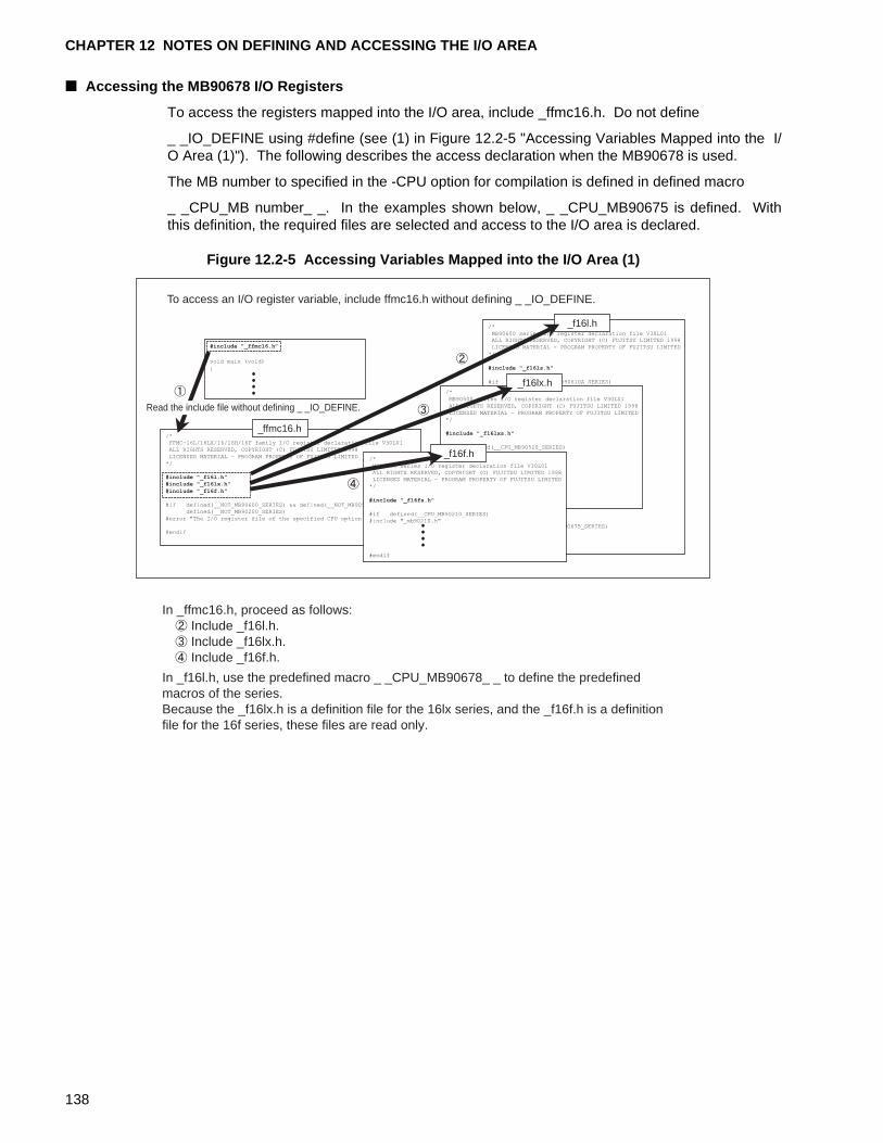
CHAPTER 12 NOTES ON DEFINING AND ACCESSING THE I/O AREA
■ Accessing the MB90678 I/O Registers
To access the registers mapped into the I/O area, include _ffmc16.h. Do not define
_ _IO_DEFINE using #define (see (1) in Figure 12.2-5 "Accessing Variables Mapped into the I/O Area (1)"). The following describes the access declaration when the MB90678 is used.
The MB number to specified in the -CPU option for compilation is defined in defined macro
_ _CPU_MB number_ _. In the examples shown below, _ _CPU_MB90675 is defined. Withthis definition, the required files are selected and access to the I/O area is declared.
Figure 12.2-5 Accessing Variables Mapped into the I/O Area (1)
In _ffmc16.h, proceed as follows: Include _f16l.h. Include _f16lx.h. Include _f16f.h.
In _f16l.h, use the predefined macro _ _CPU_MB90678_ _ to define the predefined macros of the series. Because the _f16lx.h is a definition file for the 16lx series, and the _f16f.h is a definition file for the 16f series, these files are read only.
To access an I/O register variable, include ffmc16.h without defining _ _IO_DEFINE.
#include "_ffmc16.h�
void main (void)
{
/*
FFMC-16L/16LX/16/16H/16F family I/O register declaration file V30L01
ALL RIGHTS RESERVED, COPYRIGHT (C) FUJITSU LIMITED 1998
LICENSED MATERIAL - PROGRAM PROPERTY OF FUJITSU LIMITED
*/
#include "_f16l.h"#include "_f16lx.h"
#include "_f16f.h"
#if defined(__NOT_MB90600_SERIES) && defined(__NOT_MB90500_SERIES) && ¥defined(__NOT_MB90200_SERIES)
#error "The I/O register file of the specified CPU option does not exist"
#endif
_ffmc16.h
/*
MB90600 series I/O register declaration file V30L01ALL RIGHTS RESERVED, COPYRIGHT (C) FUJITSU LIMITED 1998
LICENSED MATERIAL - PROGRAM PROPERTY OF FUJITSU LIMITED
*/
#include "_f16ls.h"
#if defined(__CPU_MB90610A_SERIES)#include "_mb90610.h"
#elif defined(__CPU_MB90620A_SERIES)
#include "_mb90620.h"
#elif defined(__CPU_MB90630A_SERIES)#include "_mb90630.h"
#elif defined(__CPU_MB90640A_SERIES)
#include "_mb90640.h"
#elif defined(__CPU_MB90650A_SERIES)
#include "_mb90650.h"
#elif defined(__CPU_MB90660A_SERIES)
#include "_mb90660.h"
#elif defined(__CPU_MB90670_SERIES)
#include "_mb90670.h"
#elif defined(__CPU_MB90675_SERIES)#include "_mb90675.h"
#endif
_f16l.h
/*
MB90500 series I/O register declaration file V30L01
ALL RIGHTS RESERVED, COPYRIGHT (C) FUJITSU LIMITED 1998
LICENSED MATERIAL - PROGRAM PROPERTY OF FUJITSU LIMITED
*/
#include "_f16lxs.h"
#if defined(__CPU_MB90520_SERIES)
#include "_mb90520.h"
#endif
_f16lx.h
/*
MB90200 series I/O register declaration file V30L01ALL RIGHTS RESERVED, COPYRIGHT (C) FUJITSU LIMITED 1998LICENSED MATERIAL - PROGRAM PROPERTY OF FUJITSU LIMITED
*/
#include "_f16fs.h"
#if defined(__CPU_MB90210_SERIES)#include "_mb90210.h"
#endif
_f16f.h
Read the include file without defining _ _IO_DEFINE.
138
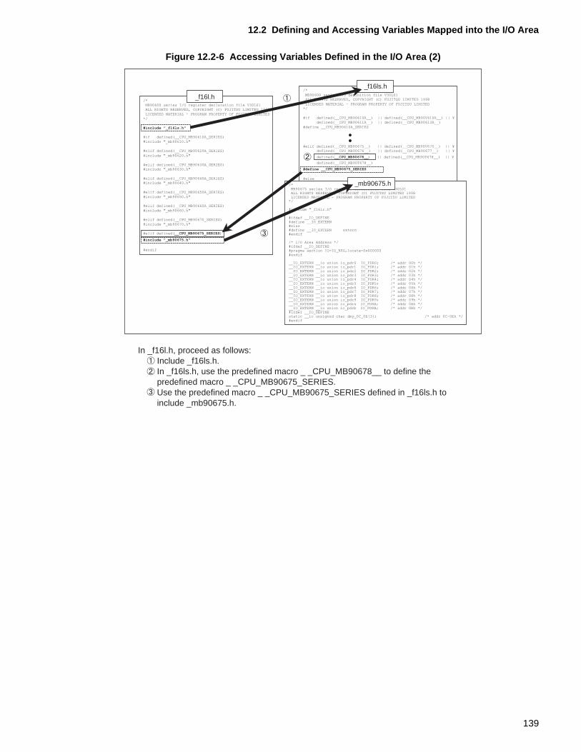
12.2 Defining and Accessing Variables Mapped into the I/O Area
Figure 12.2-6 Accessing Variables Defined in the I/O Area (2)
In _f16l.h, proceed as follows: Include _f16ls.h. In _f16ls.h, use the predefined macro _ _CPU_MB90678__ to define the predefined macro _ _CPU_MB90675_SERIES. Use the predefined macro _ _CPU_MB90675_SERIES defined in _f16ls.h to include _mb90675.h.
/*MB90600 series I/O register declaration file V30L01ALL RIGHTS RESERVED, COPYRIGHT (C) FUJITSU LIMITED 1998
LICENSED MATERIAL - PROGRAM PROPERTY OF FUJITSU LIMITED
*/
#include "_f16ls.h"
#if defined(__CPU_MB90610A_SERIES)
#include "_mb90610.h"
#elif defined(__CPU_MB90620A_SERIES)
#include "_mb90620.h"
#elif defined(__CPU_MB90630A_SERIES)#include "_mb90630.h"
#elif defined(__CPU_MB90640A_SERIES)#include "_mb90640.h"
#elif defined(__CPU_MB90650A_SERIES)
#include "_mb90650.h"
#elif defined(__CPU_MB90660A_SERIES)
#include "_mb90660.h"
#elif defined(__CPU_MB90670_SERIES)
#include "_mb90670.h"
#elif defined(__CPU_MB90675_SERIES)
#include "_mb90675.h"
#endif
_f16l.h/*
MB90600 series CPU definition file V30L01ALL RIGHTS RESERVED, COPYRIGHT (C) FUJITSU LIMITED 1998
LICENSED MATERIAL - PROGRAM PROPERTY OF FUJITSU LIMITED*/
#if defined(__CPU_MB90610A__) || defined(__CPU_MB90V610A__) || ¥defined(__CPU_MB90611A__) || defined(__CPU_MB90613A__)
#define __CPU_MB90610A_SERIES
#elif defined(__CPU_MB90675__) || defined(__CPU_MB90V670__) || ¥defined(__CPU_MB90676__) || defined(__CPU_MB90677__) || ¥
defined(__CPU_MB90678__) || defined(__CPU_MB90P678__) || ¥
defined(__CPU_MB90T678__)
#define __CPU_MB90675_SERIES
#else
#define __NOT_MB90600_SERIES
#endif
_f16ls.h
/*MB90675 series I/O register declaration file V30L01ALL RIGHTS RESERVED, COPYRIGHT (C) FUJITSU LIMITED 1998LICENSED MATERIAL - PROGRAM PROPERTY OF FUJITSU LIMITED
*/
#include "_f16lr.h"
#ifdef __IO_DEFINE#define __IO_EXTERN#else#define __IO_EXTERN extern#endif
/* I/O Area Address */#ifdef __IO_DEFINE#pragma section IO=IO_REG,locate=0x000000#endif
__IO_EXTERN __io union io_pdr0 IO_PDR0; /* addr 00h */__IO_EXTERN __io union io_pdr1 IO_PDR1; /* addr 01h */__IO_EXTERN __io union io_pdr2 IO_PDR2; /* addr 02h */__IO_EXTERN __io union io_pdr3 IO_PDR3; /* addr 03h */__IO_EXTERN __io union io_pdr4 IO_PDR4; /* addr 04h */__IO_EXTERN __io union io_pdr5 IO_PDR5; /* addr 05h */__IO_EXTERN __io union io_pdr6 IO_PDR6; /* addr 06h */__IO_EXTERN __io union io_pdr7 IO_PDR7; /* addr 07h */__IO_EXTERN __io union io_pdr8 IO_PDR8; /* addr 08h */__IO_EXTERN __io union io_pdr9 IO_PDR9; /* addr 09h */__IO_EXTERN __io union io_pdra IO_PDRA; /* addr 0Ah */__IO_EXTERN __io union io_pdrb IO_PDRB; /* addr 0Bh */#ifdef __IO_DEFINEstatic __io unsigned char dmy_0C_0E[3]; /* addr 0C-0Eh */#endif
_mb90675.h
139
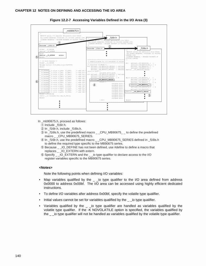
CHAPTER 12 NOTES ON DEFINING AND ACCESSING THE I/O AREA
Figure 12.2-7 Accessing Variables Defined in the I/O Area (3)
<Notes>
Note the following points when defining I/O variables:
• Map variables qualified by the _ _io type qualifier to the I/O area defined from address0x0000 to address 0x00bf. The I/O area can be accessed using highly efficient dedicatedinstructions.
• To define I/O variables after address 0x00bf, specify the volatile type qualifier.
• Initial values cannot be set for variables qualified by the _ _io type qualifier.
• Variables qualified by the _ _io type qualifier are handled as variables qualified by thevolatile type qualifier. If the -K NOVOLATILE option is specified, the variables qualified bythe _ _io type qualifier will not be handled as variables qualified by the volatile type qualifier.
In _mb90675.h, proceed as follows: Include _f16lr.h. In _f16lr.h, include _f16ls.h. In _f16ls.h, use the predefined macro _ _CPU_MB90675_ _ to define the predefined macro _ _CPU_MB90675_SERIES. In _f16lr.h, use the predefined macro _ _CPU_MB90675_SERIES defined in _f16ls.h to define the required type specific to the MB90675 series. Because _ _IO_DEFINE has not been defined, use #define to define a macro that replaces _ _IO_EXTERN with extern. Specify _ _IO_EXTERN and the _ _io type qualifier to declare access to the I/O register variables specific to the MB90675 series.
/*
MB90675 series I/O register declaration file V30L01
ALL RIGHTS RESERVED, COPYRIGHT (C) FUJITSU LIMITED 1998
LICENSED MATERIAL - PROGRAM PROPERTY OF FUJITSU LIMITED
*/
#include "_f16lr.h"
#ifdef __IO_DEFINE
#define __IO_EXTERN
#else
#define __IO_EXTERN extern
#endif
/* I/O Area Address */
#ifdef __IO_DEFINE
#pragma section IO=IO_REG,locate=0x000000
#endif
__IO_EXTERN __io union io_pdr0 IO_PDR0; /* addr 00h */
__IO_EXTERN __io union io_pdr1 IO_PDR1; /* addr 01h */
__IO_EXTERN __io union io_pdr2 IO_PDR2; /* addr 02h */
__IO_EXTERN __io union io_pdr3 IO_PDR3; /* addr 03h */
__IO_EXTERN __io union io_pdr4 IO_PDR4; /* addr 04h */
__IO_EXTERN __io union io_pdr5 IO_PDR5; /* addr 05h */
__IO_EXTERN __io union io_pdr6 IO_PDR6; /* addr 06h */
__IO_EXTERN __io union io_pdr7 IO_PDR7; /* addr 07h */
__IO_EXTERN __io union io_pdr8 IO_PDR8; /* addr 08h */
__IO_EXTERN __io union io_pdr9 IO_PDR9; /* addr 09h */
__IO_EXTERN __io union io_pdra IO_PDRA; /* addr 0Ah */
__IO_EXTERN __io union io_pdrb IO_PDRB; /* addr 0Bh */
#ifdef __IO_DEFINE
static __io unsigned char dmy_0C_0E[3]; 0C-0Eh */
#endif
/*MB90600 series I/O register declaration file V30L01
ALL RIGHTS RESERVED, COPYRIGHT (C) FUJITSU LIMITED 1998
LICENSED MATERIAL - PROGRAM PROPERTY OF FUJITSU LIMITED*/
#include "_f16ls.h"
**************************************************************/
/* Sample program for I/O variables of reload timer register. *//**************************************************************/
/* structure of TMCSR */#if defined(__CPU_MB90610A_SERIES) || defined(__CPU_MB90620A_SERIES) || ¥
defined(__CPU_MB90640A_SERIES) || defined(__CPU_MB90660A_SERIES) || ¥
defined(__CPU_MB90670_SERIES) || defined(__CPU_MB90675_SERIES)
union io_tmcsr {
unsigned short word;#if defined(__CPU_MB90610A_SERIES) || defined(__CPU_MB90620A_SERIES) || ¥
defined(__CPU_MB90640A_SERIES) ||defined(__CPU_MB90670_SERIES) || ¥
defined(__CPU_MB90675_SERIES)
struct {
} bit;
_mb90675.h
_f16lr.h
unsigned short TRG :1;
unsigned short CNTE:1;
unsigned short UF :1;
unsigned short INTE:1;
unsigned short RELD:1;unsigned short OUTL:1;
unsigned short OUTE:1;
unsigned short MOD :3;unsigned short CSL :2;
unsigned short :4;
/*MB90600 series CPU definition file V30L01
ALL RIGHTS RESERVED, COPYRIGHT (C) FUJITSU
LIMITED 1998
LICENSED MATERIAL - PROGRAM PROPERTY OF
FUJITSU LIMITED
*/
#if defined(__CPU_MB90610A__) ||
defined(__CPU_MB90V610A__) || ¥defined(__CPU_MB90611A__) ||
defined(__CPU_MB90613A__)
#define __CPU_MB90610A_SERIES
#elif defined(__CPU_MB90675__) ||defined(__CPU_MB90V670__) || ¥
defined(__CPU_MB90676__) ||defined(__CPU_MB90677__) || ¥
defined(__CPU_MB90678__) ||
defined(__CPU_MB90P678__) || ¥
defined(__CPU_MB90T678__)
#define __CPU_MB90675_SERIES
#endif
_f16ls.h
140
CHAPTER 13 MAPPING VARIABLES QUALIFIED WITH THE _ _direct TYPE QUALIFIER
This chapter describes the variables qualified by the _ _direct type qualifier and the conditions for mapping them.A variable qualified by the _ _direct type qualifier can be mapped in the page pointed to by the DPR register and accessed using direct addressing.
13.1 "Output Sections of and Access to Variables Qualified by the _ _direct Type Qualifier"
13.2 "Mapping Variables Qualified by the _ _direct Type Qualifier"
141
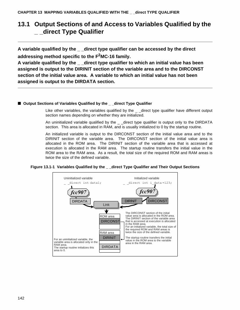
CHAPTER 13 MAPPING VARIABLES QUALIFIED WITH THE _ _direct TYPE QUALIFIER
13.1 Output Sections of and Access to Variables Qualified by the _ _direct Type Qualifier
A variable qualified by the _ _direct type qualifier can be accessed by the direct
addressing method specific to the F 2MC-16 family.A variable qualified by the _ _direct type qualifier to which an initial value has been assigned is output to the DIRINIT section of the variable area and to the DIRCONST section of the initial value area. A variable to which an initial value has not been assigned is output to the DIRDATA section.
■ Output Sections of Variables Qualified by the _ _direct Type Qualifier
Like other variables, the variables qualified by the _ _direct type qualifier have different outputsection names depending on whether they are initialized.
An uninitialized variable qualified by the _ _direct type qualifier is output only to the DIRDATAsection. This area is allocated in RAM, and is usually initialized to 0 by the startup routine.
An initialized variable is output to the DIRCONST section of the initial value area and to theDIRINIT section of the variable area. The DIRCONST section of the initial value area isallocated in the ROM area. The DIRINIT section of the variable area that is accessed atexecution is allocated in the RAM area. The startup routine transfers the initial value in theROM area to the RAM area. As a result, the total size of the required ROM and RAM areas istwice the size of the defined variable.
Figure 13.1-1 Variables Qualified by the _ _direct Type Qualifier and Their Output Sections
DIRDATA
DIRINIT
DIRCONSTDIRDATA
DIRCONST
DIRINIT
Uninitialized variable Initialized variable
Link
ROM area
RAM area
The DIRCONST section of the initial value area is allocated in the ROM area. The DIRINIT section of the variable area that is accessed at execution is allocated in the RAM area. For an initialized variable, the total size of the required ROM and RAM areas is twice the size of the defined variable.
The startup routine transfers the initial value in the ROM area to the variable area in the RAM area.
For an uninitialized variable, the variable area is allocated only in the RAM area. The startup routine initializes this area to 0.
142
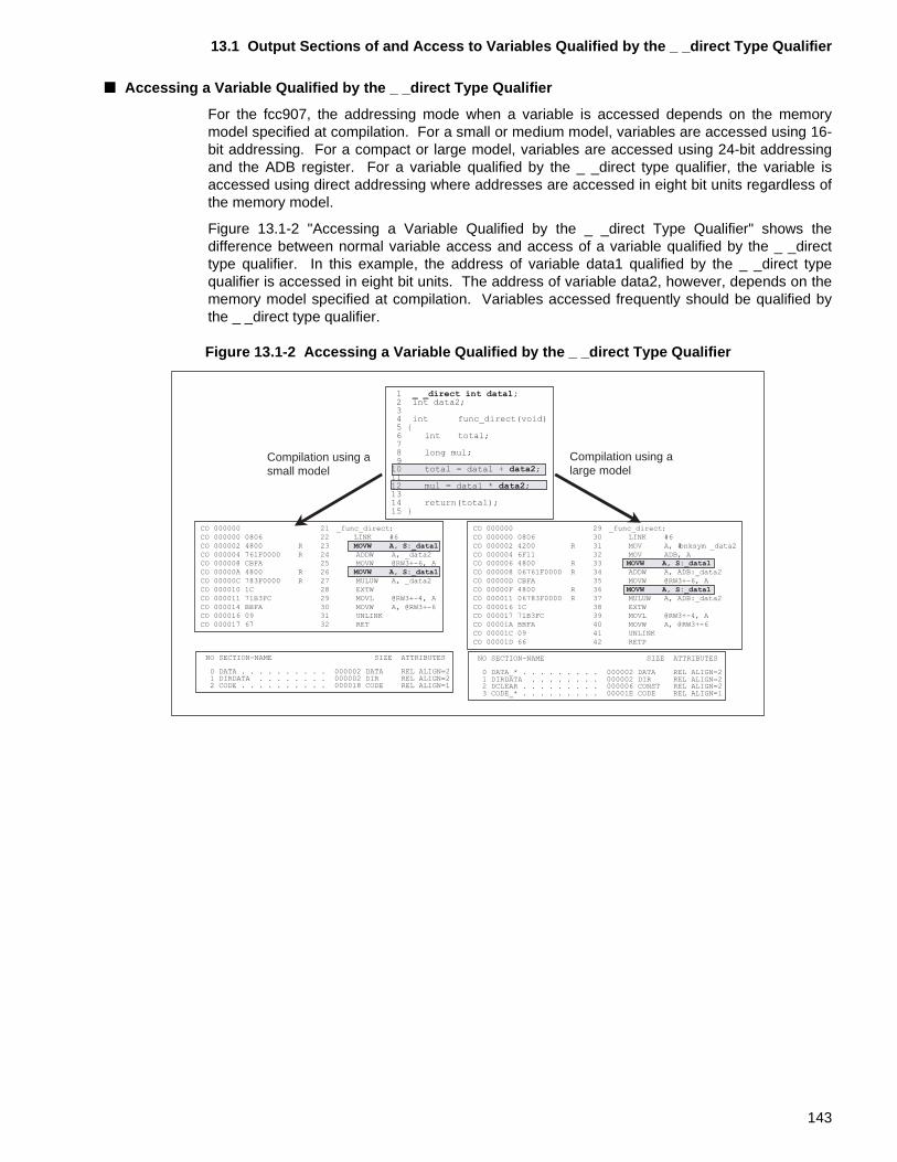
13.1 Output Sections of and Access to Variables Qualified by the _ _direct Type Qualifier
■ Accessing a Variable Qualified by the _ _direct Type Qualifier
For the fcc907, the addressing mode when a variable is accessed depends on the memorymodel specified at compilation. For a small or medium model, variables are accessed using 16-bit addressing. For a compact or large model, variables are accessed using 24-bit addressingand the ADB register. For a variable qualified by the _ _direct type qualifier, the variable isaccessed using direct addressing where addresses are accessed in eight bit units regardless ofthe memory model.
Figure 13.1-2 "Accessing a Variable Qualified by the _ _direct Type Qualifier" shows thedifference between normal variable access and access of a variable qualified by the _ _directtype qualifier. In this example, the address of variable data1 qualified by the _ _direct typequalifier is accessed in eight bit units. The address of variable data2, however, depends on thememory model specified at compilation. Variables accessed frequently should be qualified bythe _ _direct type qualifier.
Figure 13.1-2 Accessing a Variable Qualified by the _ _direct Type Qualifier
Compilation using asmall model
Compilation using alarge model
NO SECTION-NAME SIZE ATTRIBUTES
0 DATA . . . . . . . . . . 000002 DATA REL ALIGN=21 DIRDATA . . . . . . . . 000002 DIR REL ALIGN=22 CODE . . . . . . . . . . 000018 CODE REL ALIGN=1
NO SECTION-NAME SIZE ATTRIBUTES
0 DATA_* . . . . . . . . . 000002 DATA REL ALIGN=21 DIRDATA . . . . . . . . 000002 DIR REL ALIGN=22 DCLEAR . . . . . . . . . 000006 CONST REL ALIGN=23 CODE_* . . . . . . . . . 00001E CODE REL ALIGN=1
1 _ _direct int data1;2 int data2;34 int func_direct(void)5 {6 int total;78 long mul;9
10 total = data1 + data2;1112 mul = data1 * data2;1314 return(total);15 }
CO 000000 21 _func_direct:
CO 000000 0806 22 LINK #6
CO 000002 4800 R 23 MOVW A, S:_data1
CO 000004 761F0000 R 24 ADDW A, _data2
CO 000008 CBFA 25 MOVW @RW3+-6, A
CO 00000A 4800 R 26 MOVW A, S:_data1
CO 00000C 783F0000 R 27 MULUW A, _data2
CO 000010 1C 28 EXTW
CO 000011 71B3FC 29 MOVL @RW3+-4, A
CO 000014 BBFA 30 MOVW A, @RW3+-6
CO 000016 09 31 UNLINK
CO 000017 67 32 RET
CO 000000 29 _func_direct:
CO 000000 0806 30 LINK #6
CO 000002 4200 R 31 MOV A, #bnksym _data2
CO 000004 6F11 32 MOV ADB, A
CO 000006 4800 R 33 MOVW A, S:_data1
CO 000008 06761F0000 R 34 ADDW A, ADB:_data2
CO 00000D CBFA 35 MOVW @RW3+-6, A
CO 00000F 4800 R 36 MOVW A, S:_data1
CO 000011 06783F0000 R 37 MULUW A, ADB:_data2
CO 000016 1C 38 EXTW
CO 000017 71B3FC 39 MOVL @RW3+-4, A
CO 00001A BBFA 40 MOVW A, @RW3+-6
CO 00001C 09 41 UNLINK
CO 00001D 66 42 RETP
143
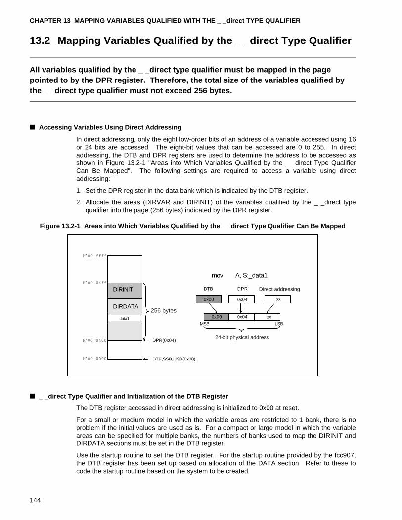
CHAPTER 13 MAPPING VARIABLES QUALIFIED WITH THE _ _direct TYPE QUALIFIER
13.2 Mapping Variables Qualified by the _ _direct Type Qualifier
All variables qualified by the _ _direct type qualifier must be mapped in the page pointed to by the DPR register. Therefore, the total size of the variables qualified by the _ _direct type qualifier must not exceed 256 bytes.
■ Accessing Variables Using Direct Addressing
In direct addressing, only the eight low-order bits of an address of a variable accessed using 16or 24 bits are accessed. The eight-bit values that can be accessed are 0 to 255. In directaddressing, the DTB and DPR registers are used to determine the address to be accessed asshown in Figure 13.2-1 "Areas into Which Variables Qualified by the _ _direct Type QualifierCan Be Mapped". The following settings are required to access a variable using directaddressing:
1. Set the DPR register in the data bank which is indicated by the DTB register.
2. Allocate the areas (DIRVAR and DIRINIT) of the variables qualified by the _ _direct typequalifier into the page (256 bytes) indicated by the DPR register.
Figure 13.2-1 Areas into Which Variables Qualified by the _ _direct Type Qualifier Can Be Mapped
■ _ _direct Type Qualifier and Initialization of the DTB Register
The DTB register accessed in direct addressing is initialized to 0x00 at reset.
For a small or medium model in which the variable areas are restricted to 1 bank, there is noproblem if the initial values are used as is. For a compact or large model in which the variableareas can be specified for multiple banks, the numbers of banks used to map the DIRINIT andDIRDATA sections must be set in the DTB register.
Use the startup routine to set the DTB register. For the startup routine provided by the fcc907,the DTB register has been set up based on allocation of the DATA section. Refer to these tocode the startup routine based on the system to be created.
data1
DIRDATA
DTB,SSB,USB(0x00)
DPR(0x04)
256 bytes
0x00 0x04
0x00 0x04 xx
DTB DPR Direct addressing
24-bit physical address
MSB LSB
mov A, S:_data1
DIRINIT
xx
144
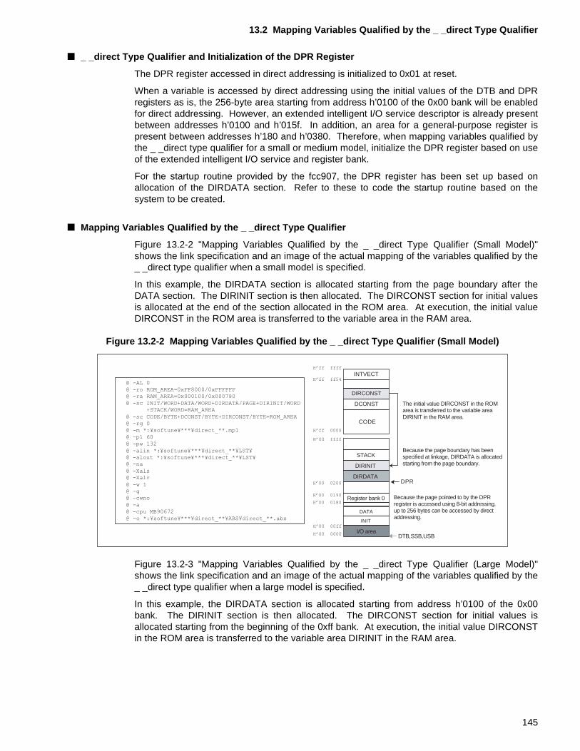
13.2 Mapping Variables Qualified by the _ _direct Type Qualifier
■ _ _direct Type Qualifier and Initialization of the DPR Register
The DPR register accessed in direct addressing is initialized to 0x01 at reset.
When a variable is accessed by direct addressing using the initial values of the DTB and DPRregisters as is, the 256-byte area starting from address h’0100 of the 0x00 bank will be enabledfor direct addressing. However, an extended intelligent I/O service descriptor is already presentbetween addresses h’0100 and h’015f. In addition, an area for a general-purpose register ispresent between addresses h’180 and h’0380. Therefore, when mapping variables qualified bythe _ _direct type qualifier for a small or medium model, initialize the DPR register based on useof the extended intelligent I/O service and register bank.
For the startup routine provided by the fcc907, the DPR register has been set up based onallocation of the DIRDATA section. Refer to these to code the startup routine based on thesystem to be created.
■ Mapping Variables Qualified by the _ _direct Type Qualifier
Figure 13.2-2 "Mapping Variables Qualified by the _ _direct Type Qualifier (Small Model)"shows the link specification and an image of the actual mapping of the variables qualified by the_ _direct type qualifier when a small model is specified.
In this example, the DIRDATA section is allocated starting from the page boundary after theDATA section. The DIRINIT section is then allocated. The DIRCONST section for initial valuesis allocated at the end of the section allocated in the ROM area. At execution, the initial valueDIRCONST in the ROM area is transferred to the variable area in the RAM area.
Figure 13.2-2 Mapping Variables Qualified by the _ _direct Type Qualifier (Small Model)
Figure 13.2-3 "Mapping Variables Qualified by the _ _direct Type Qualifier (Large Model)"shows the link specification and an image of the actual mapping of the variables qualified by the_ _direct type qualifier when a large model is specified.
In this example, the DIRDATA section is allocated starting from address h’0100 of the 0x00bank. The DIRINIT section is then allocated. The DIRCONST section for initial values isallocated starting from the beginning of the 0xff bank. At execution, the initial value DIRCONSTin the ROM area is transferred to the variable area DIRINIT in the RAM area.
INTVECT
DIRCONST
DCONST
CODE
STACK
DIRINIT
DIRDATA
INIT
DATA
DPR
DTB,SSB,USB
Register bank 0
I/O area
The initial value DIRCONST in the ROM area is transferred to the variable area DIRINIT in the RAM area.
Because the page boundary has been specified at linkage, DIRDATA is allocated starting from the page boundary.
Because the page pointed to by the DPR register is accessed using 8-bit addressing, up to 256 bytes can be accessed by direct addressing.
H�ff ffff
H�ff ff54
H�ff 0000
H�00 ffff
H�00 0000
H�00 00ff
H�00 0180
H�00 0190
H�00 0200
@ -AL 0@ -ro ROM_AREA=0xFF8000/0xFFFFFF@ -ra RAM_AREA=0x000100/0x000780
@ -sc INIT/WORD+DATA/WORD+DIRDATA/PAGE+DIRINIT/WORD+STACK/WORD=RAM_AREA
@ -sc CODE/BYTE+DCONST/BYTE+DIRCONST/BYTE=ROM_AREA@ -rg 0@ -m *:¥softune¥***¥direct_**.mp1
@ -pl 60@ -pw 132
@ -alin *:¥softune¥***¥direct_**¥LST¥@ -alout *:¥softune¥***¥direct_**¥LST¥@ -na
@ -Xals@ -Xalr
@ -w 1@ -g@ -cwno
@ -a@ -cpu MB90672
@ -o *:¥softune¥***¥direct_**¥ABS¥direct_**.abs
145
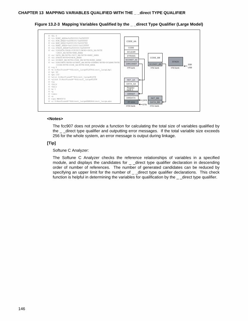
CHAPTER 13 MAPPING VARIABLES QUALIFIED WITH THE _ _direct TYPE QUALIFIER
Figure 13.2-3 Mapping Variables Qualified by the _ _direct Type Qualifier (Large Model)
<Notes>
The fcc907 does not provide a function for calculating the total size of variables qualified bythe _ _direct type qualifier and outputting error messages. If the total variable size exceeds256 for the whole system, an error message is output during linkage.
[Tip]
Softune C Analyzer:
The Softune C Analyzer checks the reference relationships of variables in a specifiedmodule, and displays the candidates for _ _direct type qualifier declaration in descendingorder of number of references. The number of generated candidates can be reduced byspecifying an upper limit for the number of _ _direct type qualifier declarations. This checkfunction is helpful in determining the variables for qualification by the _ _direct type qualifier.
DIRDATA
DIRINIT
DATA_AA
INIT_AA
DATA_BB
INIT_BB
DIRCONST
DCONST_AA
DTRANS
DCLEAR
CODE
CODE_AA
CODE_BB
DCONST_BB
DPR
DTB
SSB
USB
STACK
H'ff bank H'fe bank H'fd bank
H'01 bankH'00 bank
Register bank 0
I/O area
@ -AL 0@ -ro ROM2_AREA=0xFE0000/0xFEFFFF@ -ro ROM_AREA=0xFF8000/0xFFFFFF@ -ra RAM_AREA=0x000100/0x000780@ -ra RAM2_AREA=0x010000/0x01FFFF@ -ra STACK_AREA=0xFD0000/0xFDFFFF@ -sc DIRDATA/PAGE+DIRINIT/WORD+DATA_AA/BYTE
+INIT_AA/BYTE=RAM_AREA@ -sc DATA_BB/BYTE+INIT_BB/BYTE=RAM2_AREA@ -sc STACK/BYTE=STACK_AREA@ -sc DCONST_BB/BYTE+CODE_BB/BYTE=ROM2_AREA@ -sc DIRCONST/BYTE+DCONST_AA/BYTE+DTRANS/BYTE+DCLEAR/BYTE
+CODE/BYTE+CODE_AA/BYTE=ROM_AREA@ -rg 0@ -m D:¥softune¥**¥direct_large¥LST¥direct_large.mp1@ -pl 60@ -pw 132@ -alin D:¥softune¥**¥direct_large¥LST¥@ -alout D:¥softune¥**¥direct_large¥LST¥@ -na@ -Xals@ -Xalr@ -w 1@ -g@ -cwno@ -a@ -cpu MB90672@ -o D:¥softune¥**¥direct_large¥ABS¥direct_large.abs
146
CHAPTER 14 CREATING AND REGISTERING INTERRUPT FUNCTIONS
This chapter provides notes for creation and registration of interrupt functions.
The F2MC-16 family of microcontrollers has various resources for generating interrupts. The generation and processing of interrupts requires to set initial values for hardware and software.
14.1 "F2MC-16 Family Interrupts"
14.2 "Required Hardware Settings for Interrupts"
14.3 "Using the _ _interrupt Type Qualifier to Define Interrupt Functions"
14.4 "Setting of Interrupt Vectors"
147
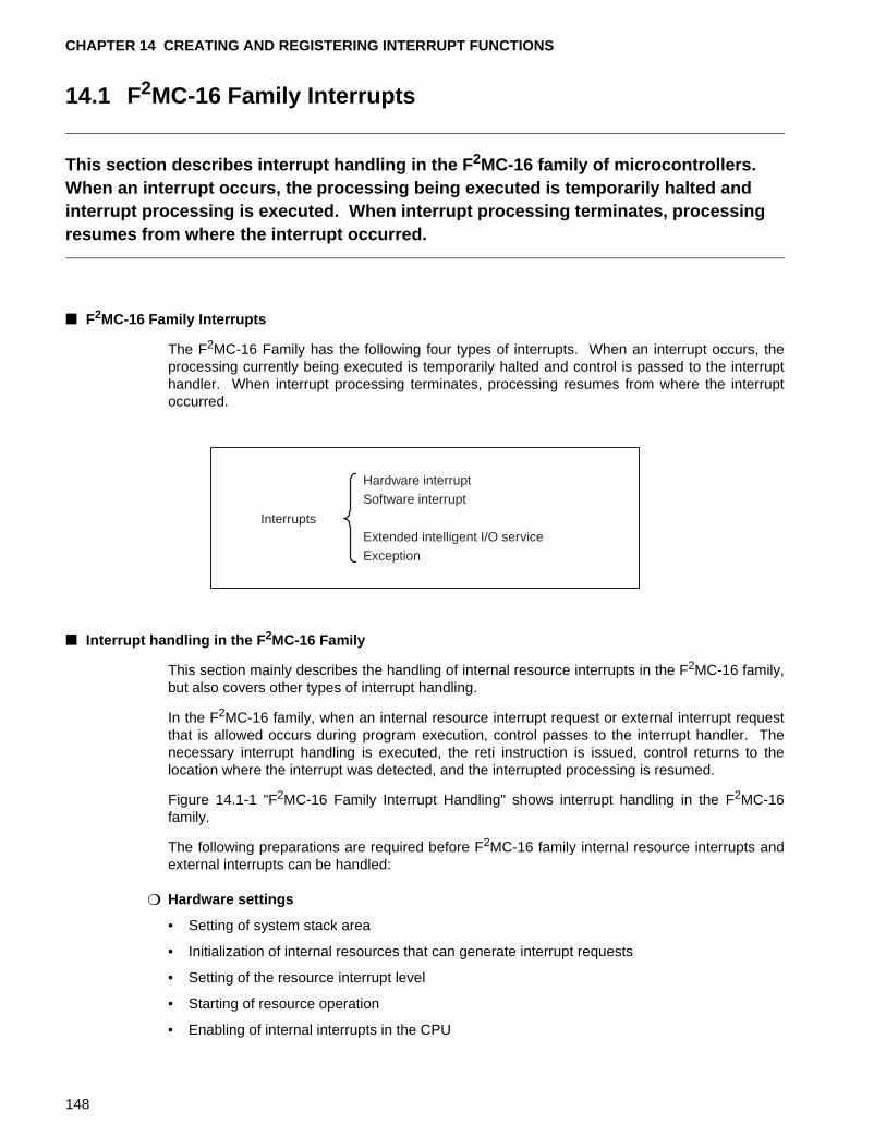
CHAPTER 14 CREATING AND REGISTERING INTERRUPT FUNCTIONS
14.1 F2MC-16 Family Interrupts
This section describes interrupt handling in the F 2MC-16 family of microcontrollers.When an interrupt occurs, the processing being executed is temporarily halted and interrupt processing is executed. When interrupt processing terminates, processing resumes from where the interrupt occurred.
■ F2MC-16 Family Interrupts
The F2MC-16 Family has the following four types of interrupts. When an interrupt occurs, theprocessing currently being executed is temporarily halted and control is passed to the interrupthandler. When interrupt processing terminates, processing resumes from where the interruptoccurred.
■ Interrupt handling in the F 2MC-16 Family
This section mainly describes the handling of internal resource interrupts in the F2MC-16 family,but also covers other types of interrupt handling.
In the F2MC-16 family, when an internal resource interrupt request or external interrupt requestthat is allowed occurs during program execution, control passes to the interrupt handler. Thenecessary interrupt handling is executed, the reti instruction is issued, control returns to thelocation where the interrupt was detected, and the interrupted processing is resumed.
Figure 14.1-1 "F2MC-16 Family Interrupt Handling" shows interrupt handling in the F2MC-16family.
The following preparations are required before F2MC-16 family internal resource interrupts andexternal interrupts can be handled:
❍ Hardware settings
• Setting of system stack area
• Initialization of internal resources that can generate interrupt requests
• Setting of the resource interrupt level
• Starting of resource operation
• Enabling of internal interrupts in the CPU
Interrupts
Hardware interrupt Software interrupt
Extended intelligent I/O service Exception
148
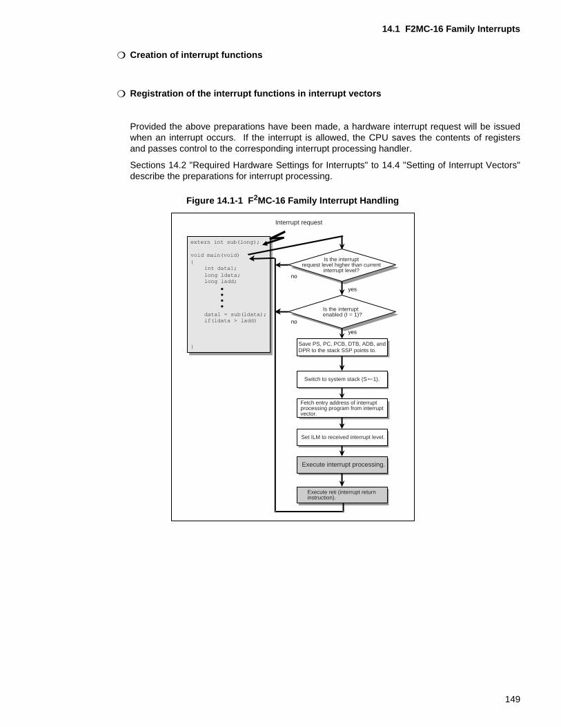
14.1 F2MC-16 Family Interrupts
❍ Creation of interrupt functions
❍ Registration of the interrupt functions in interrupt vectors
Provided the above preparations have been made, a hardware interrupt request will be issuedwhen an interrupt occurs. If the interrupt is allowed, the CPU saves the contents of registersand passes control to the corresponding interrupt processing handler.
Sections 14.2 "Required Hardware Settings for Interrupts" to 14.4 "Setting of Interrupt Vectors"describe the preparations for interrupt processing.
Figure 14.1-1 F 2MC-16 Family Interrupt Handling
yes
yes
no
no
Interrupt request
Is the interruptrequest level higher than current
interrupt level?
Is the interruptenabled (I = 1)?
Save PS, PC, PCB, DTB, ADB, and DPR to the stack SSP points to.
Switch to system stack (S 1).
Fetch entry address of interrupt processing program from interrupt vector.
Set ILM to received interrupt level.
Execute interrupt processing.
Execute reti (interrupt return instruction).
149
CHAPTER 14 CREATING AND REGISTERING INTERRUPT FUNCTIONS
14.2 Required Hardware Settings for Interrupts
This section describes the required hardware settings for interrupt handling.The following steps must be performed to enable interrupt handling.• Setting the stack area• Initial value of resources that can generate interrupt requests• Setting the resource interrupt level• Starting resource operation• Enabling CPU interrupts
■ Required Hardware Settings for Interrupts
The following steps must be performed to enable interrupt processing for F2MC-16 familymicrocontrollers:
• Setting the system stack area
• Initial value of resources that can generate interrupt requests
• Setting the resource interrupt level
• Starting resource operation
• Enabling CPU interrupts
Sections 14.2.1 "Setting the System Stack Area" to 14.2.5 "Enabling CPU Interrupts" describethe required initializations.
150
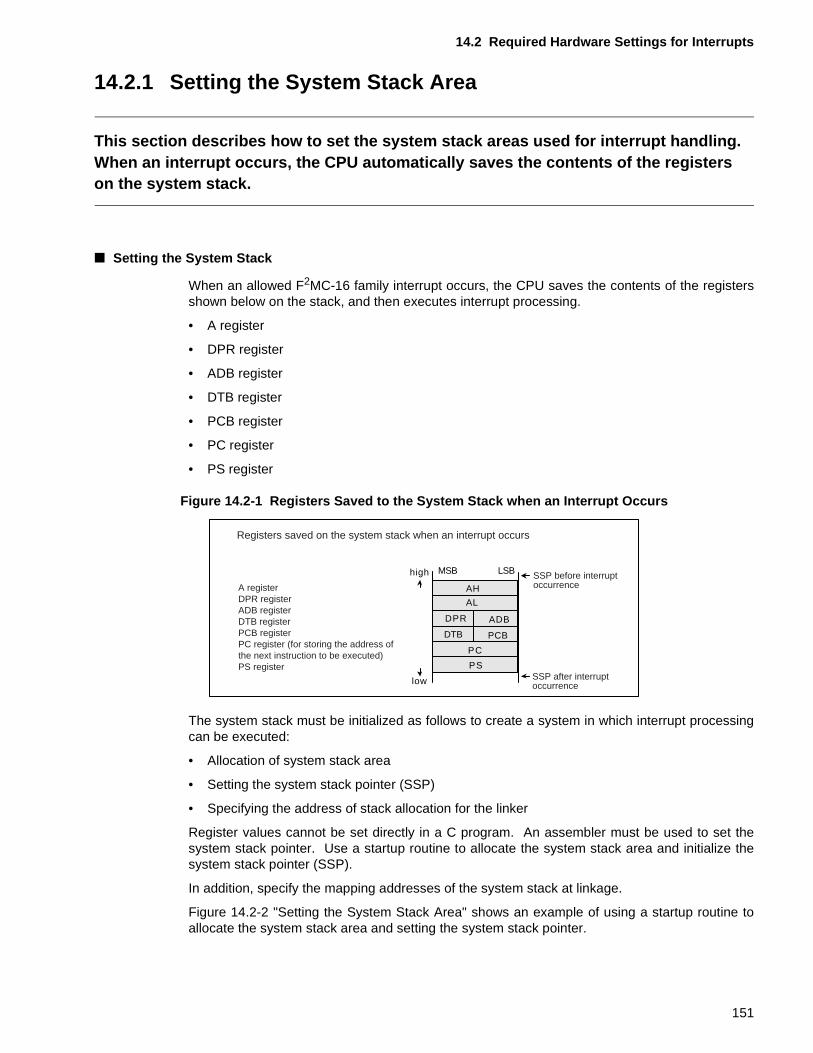
14.2 Required Hardware Settings for Interrupts
14.2.1 Setting the System Stack Area
This section describes how to set the system stack areas used for interrupt handling.When an interrupt occurs, the CPU automatically saves the contents of the registers on the system stack.
■ Setting the System Stack
When an allowed F2MC-16 family interrupt occurs, the CPU saves the contents of the registersshown below on the stack, and then executes interrupt processing.
• A register
• DPR register
• ADB register
• DTB register
• PCB register
• PC register
• PS register
Figure 14.2-1 Registers Saved to the System Stack when an Interrupt Occurs
The system stack must be initialized as follows to create a system in which interrupt processingcan be executed:
• Allocation of system stack area
• Setting the system stack pointer (SSP)
• Specifying the address of stack allocation for the linker
Register values cannot be set directly in a C program. An assembler must be used to set thesystem stack pointer. Use a startup routine to allocate the system stack area and initialize thesystem stack pointer (SSP).
In addition, specify the mapping addresses of the system stack at linkage.
Figure 14.2-2 "Setting the System Stack Area" shows an example of using a startup routine toallocate the system stack area and setting the system stack pointer.
PC
PS
high
low
AH
AL
DPR ADB
DTB PCB
MSB LSB
A register DPR register ADB register DTB register PCB registerPC register (for storing the address of the next instruction to be executed) PS register
SSP before interruptoccurrence
SSP after interruptoccurrence
Registers saved on the system stack when an interrupt occurs
151
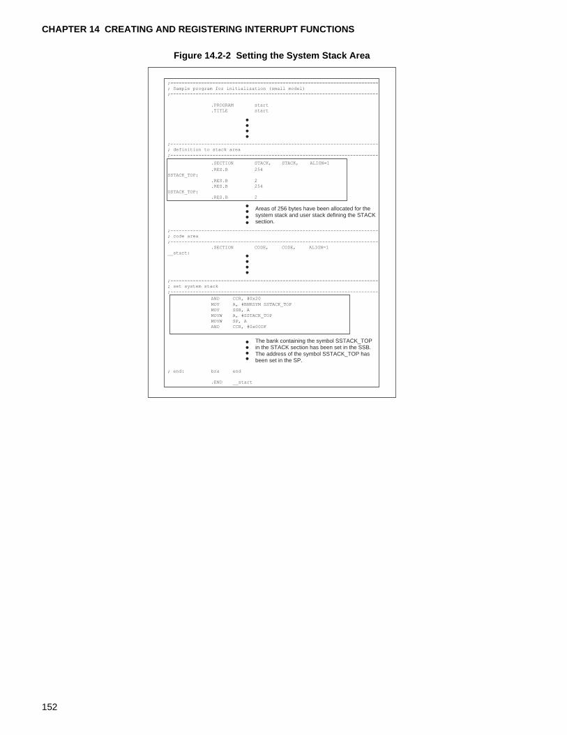
CHAPTER 14 CREATING AND REGISTERING INTERRUPT FUNCTIONS
Figure 14.2-2 Setting the System Stack Area
Areas of 256 bytes have been allocated for the system stack and user stack defining the STACK section.
The bank containing the symbol SSTACK_TOP in the STACK section has been set in the SSB. The address of the symbol SSTACK_TOP has been set in the SP.
;==========================================================================
; Sample program for initialization (small model)
;--------------------------------------------------------------------------
.PROGRAM start
.TITLE start
;--------------------------------------------------------------------------
; definition to stack area
;--------------------------------------------------------------------------
.SECTION STACK, STACK, ALIGN=1
.RES.B 254
SSTACK_TOP:
.RES.B 2
.RES.B 254
USTACK_TOP:
.RES.B 2
;--------------------------------------------------------------------------
; code area
;--------------------------------------------------------------------------
.SECTION CODE, CODE, ALIGN=1
__start:
;--------------------------------------------------------------------------
; set system stack
;--------------------------------------------------------------------------
AND CCR, #0x20
MOV A, #BNKSYM SSTACK_TOP
MOV SSB, A
MOVW A, #SSTACK_TOP
MOVW SP, A
AND CCR, #0x00DF
; end: bra end
.END __start
152
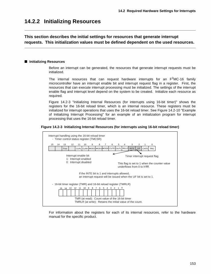
14.2 Required Hardware Settings for Interrupts
14.2.2 Initializing Resources
This section describes the initial settings for resources that generate interrupt requests. This initialization values must be defined dependent on the used resources.
■ Initializing Resources
Before an interrupt can be generated, the resources that generate interrupt requests must beinitialized.
The internal resources that can request hardware interrupts for an F2MC-16 familymicrocontroller have an interrupt enable bit and interrupt request flag in a register. First, theresources that can execute interrupt processing must be initialized. The settings of the interruptenable flag and interrupt level depend on the system to be created. Initialize each resource asrequired.
Figure 14.2-3 "Initializing Internal Resources (for interrupts using 16-bit timer)" shows theregisters for the 16-bit reload timer, which is an internal resource. These registers must beinitialized for interrupt operations that uses the 16-bit reload timer. See Figure 14.2-10 "Exampleof Initializing Interrupt Processing" for an example of an initialization program for interruptprocessing that uses the 16-bit reload timer.
Figure 14.2-3 Initializing Internal Resources (for interrupts using 16-bit reload timer)
For information about the registers for each of its internal resources, refer to the hardwaremanual for the specific product.
91112131415 8
CLR1
0123456789101112131415
CLR0 MOD2 MOD1
7 6
CUTE
5
OUTL
4 3 2 1 0
RELO INTE UF CNTE TRG
10
MOD0
Interrupt handling using the 16-bit reload timer - Timer control status register (TMCSR)
Free
Interrupt enable bit1: Interrupt enabled 0: Interrupt disabled
Timer interrupt request flag
This flag is set to 1 when the counter value underflows from 0 to h'ffff.
If the INTE bit is 1 and interrupts allowed, an interrupt request will be issued when the UF bit is set to 1.
- 16-bit timer register (TMR) and 16-bit reload register (TMRLR)
TMR (at read): Count value of the 16-bit timer TMRLR (at write): Retains the initial value of the count.
153
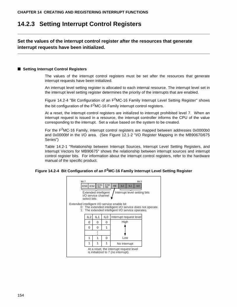
CHAPTER 14 CREATING AND REGISTERING INTERRUPT FUNCTIONS
14.2.3 Setting Interrupt Control Registers
Set the values of the interrupt control register after the resources that generate interrupt requests have been initialized.
■ Setting Interrupt Control Registers
The values of the interrupt control registers must be set after the resources that generateinterrupt requests have been initialized.
An interrupt level setting register is allocated to each internal resource. The interrupt level set inthe interrupt level setting register determines the priority of the interrupts that are enabled.
Figure 14.2-4 "Bit Configuration of an F2MC-16 Family Interrupt Level Setting Register" shows
the bit configuration of the F2MC-16 Family interrupt control registers.
At a reset, the interrupt control registers are initialized to interrupt prohibited level 7. When aninterrupt request is issued in a resource, the interrupt controller informs the CPU of the valuecorresponding to the interrupt. Set a value based on the system to be created.
For the F2MC-16 Family, interrupt control registers are mapped between addresses 0x0000b0and 0x0000bf in the I/O area. (See Figure 12.1-2 "I/O Register Mapping in the MB90670/675Series")
Table 14.2-1 "Relationship between Interrupt Sources, Interrupt Level Setting Registers, andInterrupt Vectors for MB90675" shows the relationship between interrupt sources and interruptcontrol register bits. For information about the interrupt control registers, refer to the hardwaremanual of the specific product.
Figure 14.2-4 Bit Configuration of an F 2MC-16 Family Interrupt Level Setting Register
Bit 7 Bit 0
ICS3 ICS2 ICS1/S1 ISE IL2 IL1 IL0ICS0
/S0
IL2 IL1 IL0
0 0 0
0 0 1
1 1 0
1 1 1
Extended intelligentI/O service channelselect bits
Interrupt level setting bits
Extended intelligent I/O service enable bit 0: The extended intelligent I/O service does not operate. 1: The extended intelligent I/O service operates.
Interrupt request level
At a reset, the interrupt request level is initialized to 7 (no interrupt).
No interrupt
High
Low
154
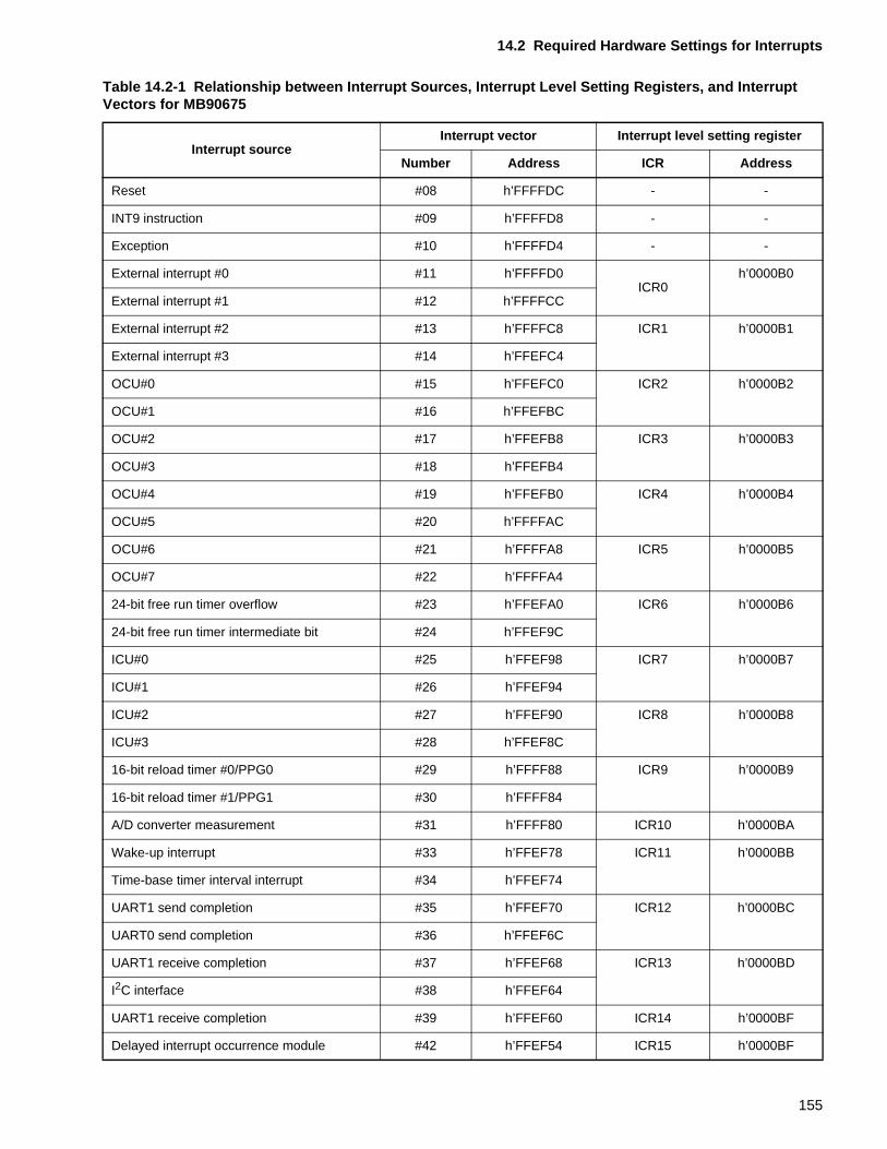
14.2 Required Hardware Settings for Interrupts
Table 14.2-1 Relationship between Interrupt Sources, Interrupt Level Setting Registers, and Interrupt Vectors for MB90675
Interrupt sourceInterrupt vector Interrupt level setting register
Number Address ICR Address
Reset #08 h’FFFFDC - -
INT9 instruction #09 h’FFFFD8 - -
Exception #10 h’FFFFD4 - -
External interrupt #0 #11 h’FFFFD0ICR0
h’0000B0
External interrupt #1 #12 h’FFFFCC
External interrupt #2 #13 h’FFFFC8 ICR1 h’0000B1
External interrupt #3 #14 h’FFEFC4
OCU#0 #15 h’FFEFC0 ICR2 h’0000B2
OCU#1 #16 h’FFEFBC
OCU#2 #17 h’FFEFB8 ICR3 h’0000B3
OCU#3 #18 h’FFEFB4
OCU#4 #19 h’FFEFB0 ICR4 h’0000B4
OCU#5 #20 h’FFFFAC
OCU#6 #21 h’FFFFA8 ICR5 h’0000B5
OCU#7 #22 h’FFFFA4
24-bit free run timer overflow #23 h’FFEFA0 ICR6 h’0000B6
24-bit free run timer intermediate bit #24 h’FFEF9C
ICU#0 #25 h’FFEF98 ICR7 h’0000B7
ICU#1 #26 h’FFEF94
ICU#2 #27 h’FFEF90 ICR8 h’0000B8
ICU#3 #28 h’FFEF8C
16-bit reload timer #0/PPG0 #29 h’FFFF88 ICR9 h’0000B9
16-bit reload timer #1/PPG1 #30 h’FFFF84
A/D converter measurement #31 h’FFFF80 ICR10 h’0000BA
Wake-up interrupt #33 h’FFEF78 ICR11 h’0000BB
Time-base timer interval interrupt #34 h’FFEF74
UART1 send completion #35 h’FFEF70 ICR12 h’0000BC
UART0 send completion #36 h’FFEF6C
UART1 receive completion #37 h’FFEF68 ICR13 h’0000BD
I2C interface #38 h’FFEF64
UART1 receive completion #39 h’FFEF60 ICR14 h’0000BF
Delayed interrupt occurrence module #42 h’FFEF54 ICR15 h’0000BF
155
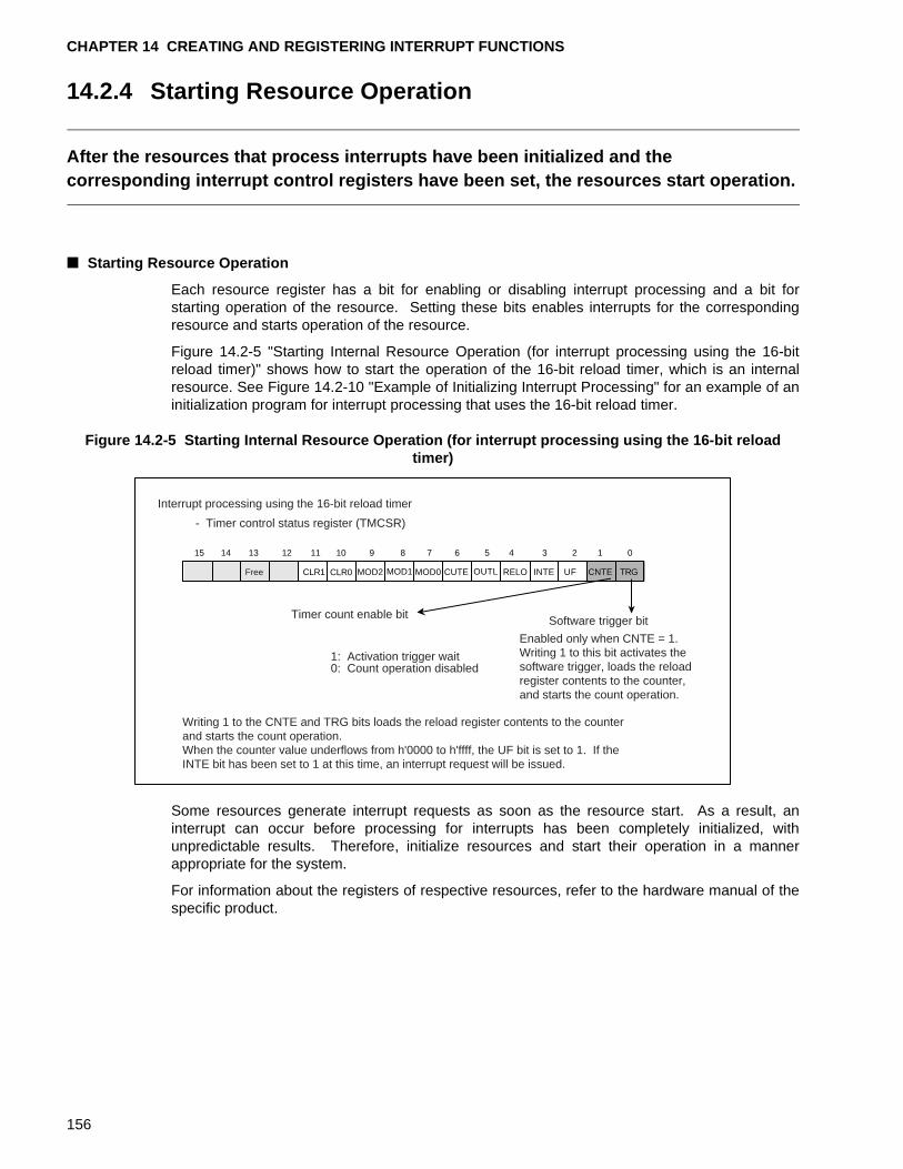
CHAPTER 14 CREATING AND REGISTERING INTERRUPT FUNCTIONS
14.2.4 Starting Resource Operation
After the resources that process interrupts have been initialized and the corresponding interrupt control registers have been set, the resources start operation.
■ Starting Resource Operation
Each resource register has a bit for enabling or disabling interrupt processing and a bit forstarting operation of the resource. Setting these bits enables interrupts for the correspondingresource and starts operation of the resource.
Figure 14.2-5 "Starting Internal Resource Operation (for interrupt processing using the 16-bitreload timer)" shows how to start the operation of the 16-bit reload timer, which is an internalresource. See Figure 14.2-10 "Example of Initializing Interrupt Processing" for an example of aninitialization program for interrupt processing that uses the 16-bit reload timer.
Figure 14.2-5 Starting Internal Resource Operation (for interrupt processing using the 16-bit reload timer)
Some resources generate interrupt requests as soon as the resource start. As a result, aninterrupt can occur before processing for interrupts has been completely initialized, withunpredictable results. Therefore, initialize resources and start their operation in a mannerappropriate for the system.
For information about the registers of respective resources, refer to the hardware manual of thespecific product.
Interrupt processing using the 16-bit reload timer
- Timer control status register (TMCSR)
Timer count enable bit Software trigger bit
91112131415 8
CLR1 CLR0 MOD2 MOD1
7 6
CUTE
5
OUTL
4 3 2 1 0
RELO INTE UF CNTE TRG
10
MOD0
Writing 1 to the CNTE and TRG bits loads the reload register contents to the counter and starts the count operation. When the counter value underflows from h'0000 to h'ffff, the UF bit is set to 1. If the INTE bit has been set to 1 at this time, an interrupt request will be issued.
Free
1: Activation trigger wait 0: Count operation disabled
Enabled only when CNTE = 1. Writing 1 to this bit activates the software trigger, loads the reload register contents to the counter, and starts the count operation.
156
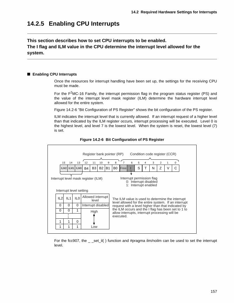
14.2 Required Hardware Settings for Interrupts
14.2.5 Enabling CPU Interrupts
This section describes how to set CPU interrupts to be enabled.The I flag and ILM value in the CPU determine the interrupt level allowed for the system.
■ Enabling CPU Interrupts
Once the resources for interrupt handling have been set up, the settings for the receiving CPUmust be made.
For the F2MC-16 Family, the interrupt permission flag in the program status register (PS) andthe value of the interrupt level mask register (ILM) determine the hardware interrupt levelallowed for the entire system.
Figure 14.2-6 "Bit Configuration of PS Register" shows the bit configuration of the PS register.
ILM indicates the interrupt level that is currently allowed. If an interrupt request of a higher levelthan that indicated by the ILM register occurs, interrupt processing will be executed. Level 0 isthe highest level, and level 7 is the lowest level. When the system is reset, the lowest level (7)is set.
Figure 14.2-6 Bit Configuration of PS Register
For the fcc907, the _ _set_il( ) function and #pragma ilm/noilm can be used to set the interruptlevel.
CVZNTSI
Register bank pointer (RP)
15 14 13 12 11 10 9 8 7 6 5 4 3 2 1 0
Condition code register (CCR)
Interrupt level setting
B0B1B2B3B4ILM0ILM2 ILM1
IL2 IL1 IL0 Allowed interruptlevel
0 0 0
High
Low
Interrupt disabled
0 0 1
1 1 0
1 1 1
The ILM value is used to determine the interrupt level allowed for the entire system. If an interrupt request with a level higher than that indicated by the ILM occurs and the I flag has been set to 1 to allow interrupts, interrupt processing will be executed.
Free
Interrupt level mask register (ILM) Interrupt permission flag 0: Interrupt disabled 1: Interrupt enabled
157
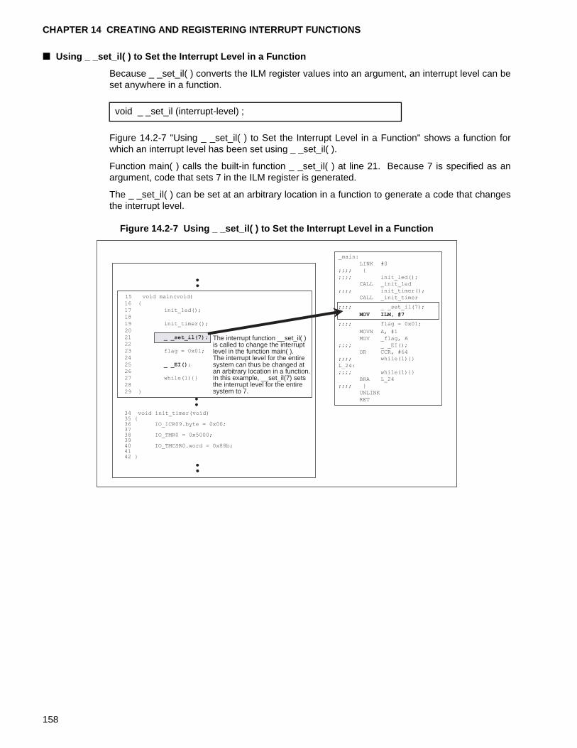
CHAPTER 14 CREATING AND REGISTERING INTERRUPT FUNCTIONS
■ Using _ _set_il( ) to Set the Interrupt Level in a Function
Because _ _set_il( ) converts the ILM register values into an argument, an interrupt level can beset anywhere in a function.
Figure 14.2-7 "Using _ _set_il( ) to Set the Interrupt Level in a Function" shows a function forwhich an interrupt level has been set using _ _set_il( ).
Function main( ) calls the built-in function _ _set_il( ) at line 21. Because 7 is specified as anargument, code that sets 7 in the ILM register is generated.
The _ _set_il( ) can be set at an arbitrary location in a function to generate a code that changesthe interrupt level.
Figure 14.2-7 Using _ _set_il( ) to Set the Interrupt Level in a Function
void _ _set_il (interrupt-level) ;
The interrupt function __set_il( ) is called to change the interrupt level in the function main( ). The interrupt level for the entire system can thus be changed at an arbitrary location in a function. In this example, __set_il(7) sets the interrupt level for the entire system to 7.
15 void main(void)
16 {
17 init_led();
18
19 init_timer();
20
21 _ _set_il(7);22
23 flag = 0x01;
24
25 _ _EI();26
27 while(1){}
28
29 }
34 void init_timer(void)35 {36 IO_ICR09.byte = 0x00;3738 IO_TMR0 = 0x5000;3940 IO_TMCSR0.word = 0x88b;4142 }
_main:
LINK #0
;;;; {
;;;; init_led();CALL _init_led
;;;; init_timer();
CALL _init_timer
;;;; _ _set_il(7);
MOV ILM, #7
;;;; flag = 0x01;
MOVN A, #1
MOV _flag, A
;;;; _ _EI();
OR CCR, #64
;;;; while(1){}
L_24:
;;;; while(1){}
BRA L_24
;;;; }
UNLINK
RET
158
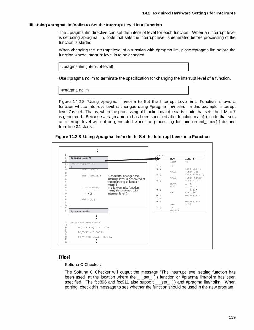
14.2 Required Hardware Settings for Interrupts
■ Using #pragma ilm/noilm to Set the Interrupt Level in a Function
The #pragma ilm directive can set the interrupt level for each function. When an interrupt levelis set using #pragma ilm, code that sets the interrupt level is generated before processing of thefunction is started.
When changing the interrupt level of a function with #pragma ilm, place #pragma ilm before thefunction whose interrupt level is to be changed.
Use #pragma noilm to terminate the specification for changing the interrupt level of a function.
Figure 14.2-8 "Using #pragma ilm/noilm to Set the Interrupt Level in a Function" shows afunction whose interrupt level is changed using #pragma ilm/noilm. In this example, interruptlevel 7 is set. That is, when the processing of function main( ) starts, code that sets the ILM to 7is generated. Because #pragma noilm has been specified after function main( ), code that setsan interrupt level will not be generated when the processing for function init_timer( ) definedfrom line 34 starts.
Figure 14.2-8 Using #pragma ilm/noilm to Set the Interrupt Level in a Function
[Tips]
Softune C Checker:
The Softune C Checker will output the message "The interrupt level setting function hasbeen used" at the location where the _ _set_il( ) function or #pragma ilm/noilm has beenspecified. The fcc896 and fcc911 also support _ _set_il( ) and #pragma ilm/noilm. Whenporting, check this message to see whether the function should be used in the new program.
#pragma ilm (interrupt-level) ;
#pragma noilm
A code that changes the interrupt level is generated at the beginning of function main( ). In this example, function main( ) is executed with interrupt level 7.
13
14 #pragma ilm(7)15
16 void main(void)
17 {
18 init_led();
19
20 init_timer();
21
22
23
24 flag = 0x01;
25
26 _ _EI();27
28 while(1){}
29
30 }
31
31 #pragma noilm
34 void init_timer(void)35 {36 IO_ICR09.byte = 0x00;3738 IO_TMR0 = 0x5000;3940 IO_TMCSR0.word = 0x88b;4142 }
_main:
MOV ILM, #7LINK #0
;;;; {
;;;; init_led();
CALL _init_led
;;;; init_timer();
CALL _init_timer
;;;; flag = 0x01;
MOVN A, #1
MOV _flag, A
;;;; _ _EI();
OR CCR, #64
;;;; while(1){}
L_24:
;;;; while(1){}
BRA L_24
;;;; }
UNLINK
159
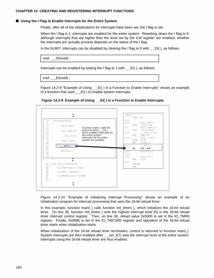
CHAPTER 14 CREATING AND REGISTERING INTERRUPT FUNCTIONS
■ Using the I Flag to Enable Interrupts for the Entire System
Finally, after all of the initializations for interrupts have been set, the I flag is set.
When the I flag is 1, interrupts are enabled for the entire system. Resetting clears the I flag to 0.Although interrupts that are higher than the level set by the ILM register are enabled, whetherthe interrupts are actually process depends on the status of the I flag.
In the fcc907, interrupts can be disabled by clearing the I flag to 0 with _ _DI( ), as follows.
Interrupts can be enabled by setting the I flag to 1 with _ _EI( ), as follows.
Figure 14.2-9 "Example of Using _ _EI( ) in a Function to Enable Interrupts" shows an exampleof a function that uses _ _EI( ) to enable system interrupts.
Figure 14.2-9 Example of Using _ _EI( ) in a Function to Enable Interrupts
Figure 14.2-10 "Example of Initializing Interrupt Processing" shows an example of aninitialization program for interrupt processing that uses the 16-bit reload timer.
In this example, function main( ) calls function init_timer( ), which initializes the 16-bit reloadtimer. On line 36, function init_timer( ) sets the highest interrupt level (0) in the 16-bit reloadtimer interrupt control register. Then, on line 38, reload value 0x5000 is set in the IO_TMR0register. Finally, 0x088b is set in the IO_TMCSR0 register and operation of the 16-bit reloadtimer starts when initialization starts.
When initialization of the 16-bit reload timer terminates, control is returned to function main( ).System interrupts are then enabled after _ _set_il(7) sets the interrupt level of the entire system.Interrupts using the 16-bit reload timer are thus enabled.
void _ _DI(void) ;
void _ _EI(void) ;
Function main( ) calls thebuilt-in function _ _EI( ),which enables interrupts forthe entire system.Interrupts for the entiresystem are enabled.
15 void main(void)
16 {
17 init_led();
18
19 init_timer();
20
21 _ _set_il(7);22
23 flag = 0x01;
24
25 _ _EI();26
27 while(1){}
28
29 }
34 void init_timer(void)35 {36 IO_ICR09.byte = 0x00;3738 IO_TMR0 = 0x5000;3940 IO_TMCSR0.word = 0x88b;4142 }
_main:
LINK #0
;;;; {
;;;; init_led();
CALL _init_led;;;; init_timer();
CALL _init_timer
;;;; _ _set_il(7);
MOV ILM, #7
;;;; flag = 0x01;
MOVN A, #1
MOV _flag, A
;;;; _ _EI();
OR CCR, #64
;;;; while(1){}
L_24:
;;;; while(1){}
BRA L_24
;;;; }
UNLINK
RET
160
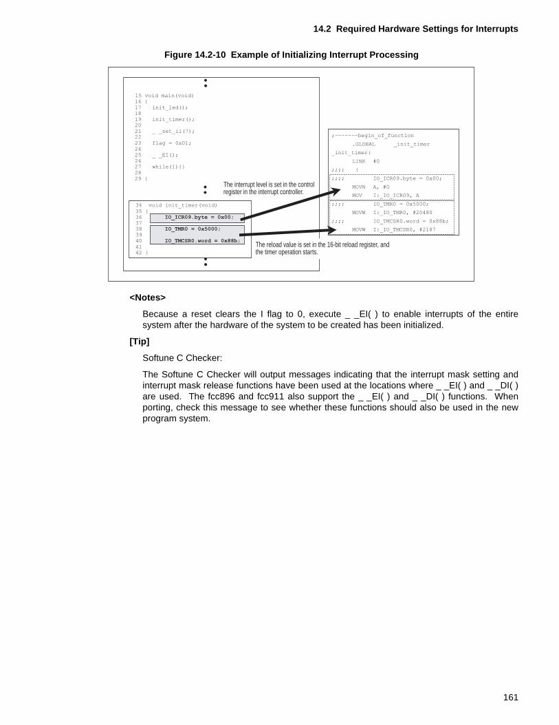
14.2 Required Hardware Settings for Interrupts
Figure 14.2-10 Example of Initializing Interrupt Processing
<Notes>
Because a reset clears the I flag to 0, execute _ _EI( ) to enable interrupts of the entiresystem after the hardware of the system to be created has been initialized.
[Tip]
Softune C Checker:
The Softune C Checker will output messages indicating that the interrupt mask setting andinterrupt mask release functions have been used at the locations where _ _EI( ) and _ _DI( )are used. The fcc896 and fcc911 also support the _ _EI( ) and _ _DI( ) functions. Whenporting, check this message to see whether these functions should also be used in the newprogram system.
The interrupt level is set in the control register in the interrupt controller.
15 void main(void)16 {17 init_led();1819 init_timer();2021 _ _set_il(7);2223 flag = 0x01;2425 _ _EI();2627 while(1){}2829 }
;-------begin_of_function
.GLOBAL _init_timer
_init_timer:
LINK #0
;;;; {
;;;; IO_ICR09.byte = 0x00;
MOVN A, #0
MOV I:_IO_ICR09, A
;;;; IO_TMR0 = 0x5000;
MOVW I:_IO_TMR0, #20480
;;;; IO_TMCSR0.word = 0x88b;
MOVW I:_IO_TMCSR0, #2187
34 void init_timer(void)35 {36 IO_ICR09.byte = 0x00;3738 IO_TMR0 = 0x5000;3940 IO_TMCSR0.word = 0x88b;4142 }
The reload value is set in the 16-bit reload register, and the timer operation starts.
161
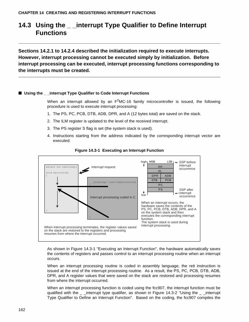
CHAPTER 14 CREATING AND REGISTERING INTERRUPT FUNCTIONS
14.3 Using the _ _interrupt Type Qualifier to Define Interrupt Functions
Sections 14.2.1 to 14.2.4 described the initialization required to execute interrupts. However, interrupt processing cannot be executed simply by initialization. Before interrupt processing can be executed, interrupt processing functions corresponding to the interrupts must be created.
■ Using the _ _interrupt Type Qualifier to Code Interrupt Functions
When an interrupt allowed by an F2MC-16 family microcontroller is issued, the followingprocedure is used to execute interrupt processing:
1. The PS, PC, PCB, DTB, ADB, DPR, and A (12 bytes total) are saved on the stack.
2. The ILM register is updated to the level of the received interrupt.
3. The PS register S flag is set (the system stack is used).
4. Instructions starting from the address indicated by the corresponding interrupt vector areexecuted.
Figure 14.3-1 Executing an Interrupt Function
As shown in Figure 14.3-1 "Executing an Interrupt Function", the hardware automatically savesthe contents of registers and passes control to an interrupt processing routine when an interruptoccurs.
When an interrupt processing routine is coded in assembly language, the reti instruction isissued at the end of the interrupt processing routine. As a result, the PS, PC, PCB, DTB, ADB,DPR, and A register values that were saved on the stack are restored and processing resumesfrom where the interrupt occurred.
When an interrupt processing function is coded using the fcc907, the interrupt function must bequalified with the _ _interrupt type qualifier, as shown in Figure 14.3-2 "Using the _ _interruptType Qualifier to Define an Interrupt Function". Based on the coding, the fcc907 compiles the
PC
PS
high
low
AH
AL
DPR ADB
DTB PCB
MSB LSB
When interrupt processing terminates, the register values saved on the stack are restored to the registers and processing resumes from where the interrupt occurred.
Interrupt request
Interrupt processing coded in C
SSP before interrupt occurrence
SSP after interrupt occurrence
When an interrupt occurs, the hardware saves the contents of the PS, PC, PCB, DTB, ADB, DPR, and A on the system stack and then executes the corresponding interrupt function. The system stack is used during interrupt processing.
162
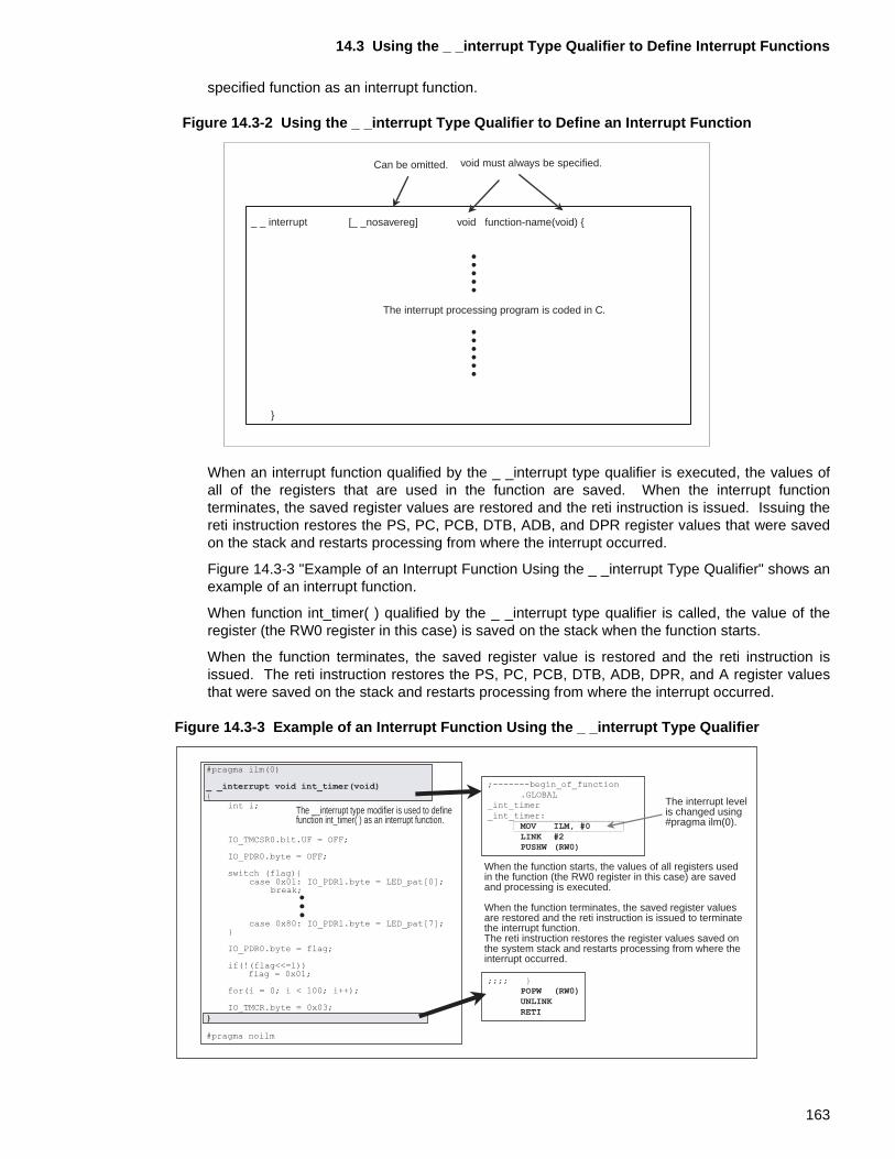
14.3 Using the _ _interrupt Type Qualifier to Define Interrupt Functions
specified function as an interrupt function.
Figure 14.3-2 Using the _ _interrupt Type Qualifier to Define an Interrupt Function
When an interrupt function qualified by the _ _interrupt type qualifier is executed, the values ofall of the registers that are used in the function are saved. When the interrupt functionterminates, the saved register values are restored and the reti instruction is issued. Issuing thereti instruction restores the PS, PC, PCB, DTB, ADB, and DPR register values that were savedon the stack and restarts processing from where the interrupt occurred.
Figure 14.3-3 "Example of an Interrupt Function Using the _ _interrupt Type Qualifier" shows anexample of an interrupt function.
When function int_timer( ) qualified by the _ _interrupt type qualifier is called, the value of theregister (the RW0 register in this case) is saved on the stack when the function starts.
When the function terminates, the saved register value is restored and the reti instruction isissued. The reti instruction restores the PS, PC, PCB, DTB, ADB, DPR, and A register valuesthat were saved on the stack and restarts processing from where the interrupt occurred.
Figure 14.3-3 Example of an Interrupt Function Using the _ _interrupt Type Qualifier
_ _ interrupt
}
Can be omitted. void must always be specified.
[_ _nosavereg] void function-name(void) {
The interrupt processing program is coded in C.
When the function starts, the values of all registers used in the function (the RW0 register in this case) are saved and processing is executed.
When the function terminates, the saved register values are restored and the reti instruction is issued to terminate the interrupt function. The reti instruction restores the register values saved on the system stack and restarts processing from where the interrupt occurred.
The __interrupt type modifier is used to define function int_timer( ) as an interrupt function.
The interrupt level is changed using #pragma ilm(0).
;-------begin_of_function
.GLOBAL
_int_timer
_int_timer:
MOV ILM, #0LINK #2PUSHW (RW0)
;;;; }POPW (RW0)UNLINKRETI
#pragma ilm(0)
_ _interrupt void int_timer(void){
int i;
IO_TMCSR0.bit.UF = OFF;
IO_PDR0.byte = OFF;
switch (flag){case 0x01: IO_PDR1.byte = LED_pat[0];
break;
case 0x80: IO_PDR1.byte = LED_pat[7];}
IO_PDR0.byte = flag;
if(!(flag<<=1))flag = 0x01;
for(i = 0; i < 100; i++);
IO_TMCR.byte = 0x03;
}
#pragma noilm
163
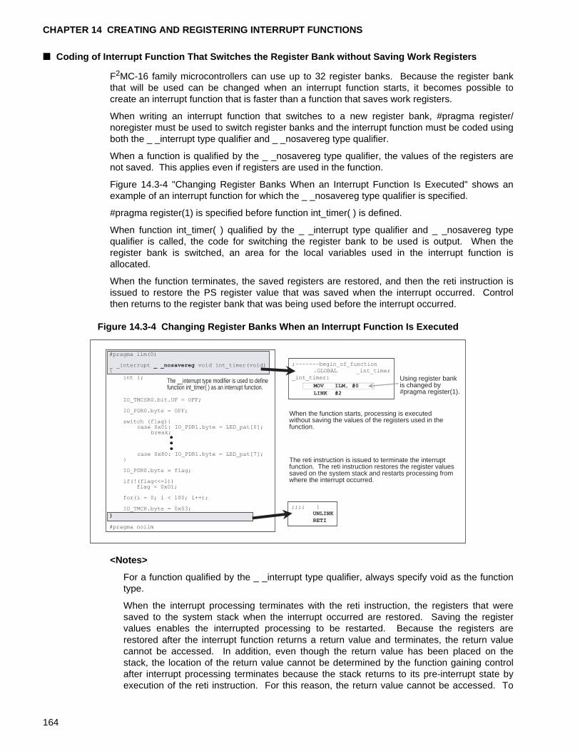
CHAPTER 14 CREATING AND REGISTERING INTERRUPT FUNCTIONS
■ Coding of Interrupt Function That Switches the Register Bank without Saving Work Registers
F2MC-16 family microcontrollers can use up to 32 register banks. Because the register bankthat will be used can be changed when an interrupt function starts, it becomes possible tocreate an interrupt function that is faster than a function that saves work registers.
When writing an interrupt function that switches to a new register bank, #pragma register/noregister must be used to switch register banks and the interrupt function must be coded usingboth the _ _interrupt type qualifier and _ _nosavereg type qualifier.
When a function is qualified by the _ _nosavereg type qualifier, the values of the registers arenot saved. This applies even if registers are used in the function.
Figure 14.3-4 "Changing Register Banks When an Interrupt Function Is Executed" shows anexample of an interrupt function for which the _ _nosavereg type qualifier is specified.
#pragma register(1) is specified before function int_timer( ) is defined.
When function int_timer( ) qualified by the _ _interrupt type qualifier and _ _nosavereg typequalifier is called, the code for switching the register bank to be used is output. When theregister bank is switched, an area for the local variables used in the interrupt function isallocated.
When the function terminates, the saved registers are restored, and then the reti instruction isissued to restore the PS register value that was saved when the interrupt occurred. Controlthen returns to the register bank that was being used before the interrupt occurred.
Figure 14.3-4 Changing Register Banks When an Interrupt Function Is Executed
<Notes>
For a function qualified by the _ _interrupt type qualifier, always specify void as the functiontype.
When the interrupt processing terminates with the reti instruction, the registers that weresaved to the system stack when the interrupt occurred are restored. Saving the registervalues enables the interrupted processing to be restarted. Because the registers arerestored after the interrupt function returns a return value and terminates, the return valuecannot be accessed. In addition, even though the return value has been placed on thestack, the location of the return value cannot be determined by the function gaining controlafter interrupt processing terminates because the stack returns to its pre-interrupt state byexecution of the reti instruction. For this reason, the return value cannot be accessed. To
When the function starts, processing is executed without saving the values of the registers used in the function.
The reti instruction is issued to terminate the interrupt function. The reti instruction restores the register values saved on the system stack and restarts processing from where the interrupt occurred.
The __interrupt type modifier is used to define function int_timer( ) as an interrupt function.
Using register bank is changed by #pragma register(1).
#pragma ilm(0)
_ _interrupt _ _nosavereg void int_timer(void){
int i;
IO_TMCSR0.bit.UF = OFF;
IO_PDR0.byte = OFF;
switch (flag){case 0x01: IO_PDR1.byte = LED_pat[0];
break;
case 0x80: IO_PDR1.byte = LED_pat[7];}
IO_PDR0.byte = flag;
if(!(flag<<=1))flag = 0x01;
for(i = 0; i < 100; i++);
IO_TMCR.byte = 0x03;
}
#pragma noilm
;-------begin_of_function
.GLOBAL _int_timer
_int_timer:
MOV ILM, #0
LINK #2
;;;; }UNLINKRETI
164
14.3 Using the _ _interrupt Type Qualifier to Define Interrupt Functions
prevent such wasteful processing, type void must be specified for the interrupt function. Ifthe processing results of an interrupt function are required, define an external variable wherethe processing results can be saved and accessed when necessary.
[Tip]
Softune C Checker processing:
The Softune C Checker will output a warning message for the location where the _ _interrupttype qualifier is specified indicating that a type qualifier for coding an interrupt function isused. The fcc896 and fcc911 support the _ _interrupt type qualifier. When porting, checkthis message to see whether the function should also be used in the new program system.
165
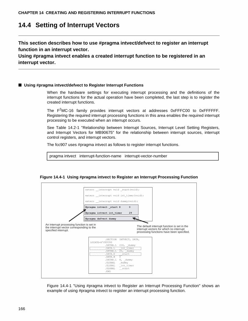
CHAPTER 14 CREATING AND REGISTERING INTERRUPT FUNCTIONS
14.4 Setting of Interrupt Vectors
This section describes how to use #pragma intvect/defvect to register an interrupt function in an interrupt vector.Using #pragma intvect enables a created interrupt function to be registered in an interrupt vector.
■ Using #pragma intvect/defvect to Register Interrupt Functions
When the hardware settings for executing interrupt processing and the definitions of theinterrupt functions for the actual operation have been completed, the last step is to register thecreated interrupt functions.
The F2MC-16 family provides interrupt vectors at addresses 0xFFFC00 to 0xFFFFFF.Registering the required interrupt processing functions in this area enables the required interruptprocessing to be executed when an interrupt occurs.
See Table 14.2-1 "Relationship between Interrupt Sources, Interrupt Level Setting Registers,and Interrupt Vectors for MB90675" for the relationship between interrupt sources, interruptcontrol registers, and interrupt vectors.
The fcc907 uses #pragma intvect as follows to register interrupt functions.
Figure 14.4-1 Using #pragma intvect to Register an Interrupt Processing Function
Figure 14.4-1 "Using #pragma intvect to Register an Interrupt Processing Function" shows anexample of using #pragma intvect to register an interrupt processing function.
pragma intvect interrupt-function-name interrupt-vector-number
An interrupt processing function is set in the interrupt vector corresponding to the specified interrupt.
The default interrupt function is set in the interrupt vectors for which no interrupt processing functions have been specified.
.SECTION INTVECT, DATA,
LOCATE=H'FFFC00
.DATAB.L 226, _dummy
.DATA.L _int_timer
.DATAB.L 20, _dummy
.DATA.E __start
.DATA.B 0
.DATAB.L 8, _dummy
.GLOBAL _dummy
.GLOBAL _int_timer
.GLOBAL __start
.END
extern __interrupt void _start(void);
extern __interrupt void int_timer(void);
extern __interrupt void dummy(void);
#pragma intvect _start 8 0
#pragma intvect int_timer 29
#pragma defvect dummy
166
14.4 Setting of Interrupt Vectors
In this example, the startup routine start( ) is registered in interrupt vector 8 and the 16-bit reloadtimer interrupt processing function int_timer( ) is registered in interrupt vector 29.
When #pragma intvect is executed, the interrupt vector table INTVECT, which is allocatedstarting at address h’fffc00, is generated. The interrupt vectors that have not been assigned avector number by #pragma intvect are filled with zeros. When #pragma defvect is executed, thespecified interrupt function is set in all the vectors that that have been filled with 0. In theexample shown in Figure 14.4-1 "Using #pragma intvect to Register an Interrupt ProcessingFunction", default interrupt function dummy is specified with #pragma defvect. Function dummyis registered in all interrupt vectors except interrupt vector 8 and 29.
<Notes>
When using #pragma intvect to set an interrupt function in a vector table, always declareaccess for a function for which the _ _interrupt type qualifier has been specified before youcode #pragma intvect. The fcc907 will output a warning message if the _ _interrupt typequalifier is omitted.
Registering of a function in an interrupt vector with #pragma intvect/defvect is only allowed inone module. If the function is registered in more than one module, an error messageindicating that a section name has been specified multiple times may be output duringlinking.
167
CHAPTER 14 CREATING AND REGISTERING INTERRUPT FUNCTIONS
168
PART IV MAPPING OBJECTS EFFECTIVELY
This part describes how to effectively map created programs into memory.When the fcc907 is used, the memory model to be selected depends on the scale of the system to be created. How objects are mapped into memory depends on the selected memory model. This part describes the following items:• Memory models and object efficiency• Mapping variables qualified by the const type qualifier• Mapping programs in which the code area exceeds 64 Kbytes• Mapping programs in which the data area exceeds 64 Kbytes
CHAPTER 15 "MEMORY MODELS AND OBJECT EFFICIENCY"
CHAPTER 16 "MAPPING VARIABLES QUALIFIED WITH THE TYPE QUALIFIER CONST"
CHAPTER 17 "MAPPING PROGRAMS IN WHICH THE CODE AREA EXCEEDS 64 Kbytes"
CHAPTER 18 "MAPPING PROGRAMS IN WHICH THE DATA AREA EXCEEDS 64 Kbytes"
169

170
CHAPTER 15 MEMORY MODELS AND OBJECT EFFICIENCY
This chapter describes the memory models that can be used by the fcc907, including object efficiency thereof.• Small model• Medium model• Compact model• Large model
15.1 "Four Memory Models"
15.2 "Memory Models and Object Efficiency"
171
CHAPTER 15 MEMORY MODELS AND OBJECT EFFICIENCY
15.1 Four Memory Models
This section describes the memory models that can be used by the fcc907. The fcc907 has small-, medium-, compact-, and large-size memory models based on memory sizes capable of being handled.
■ Memory Models of the fcc907
The fcc907 has small-, medium-, compact-, and large-size memory models as shown in Figure15.1-1 "fcc907 Memory Models" based on memory sizes capable of being handled.
Figure 15.1-1 fcc907 Memory Models
Table 15.1-1 "fcc907 Memory Models" lists the relationship between the memory models andmemory areas that are handled. In addition, Table 15.1-2 "fcc907 Memory Models andPointers" lists the relationship between the memory models and pointers at access.-
code
code
data
userstack
systemstack
data+
stack
64KB
64KB
64KB 64KB
64KB *n
64KB *n
Small model Large model
Compact model
Medium model
Table 15.1-1 fcc907 Memory Models
Small model Medium model Compact model
Large model
Data area One bank One bank Multiple banks Multiple banks
System stack One bank One bank
User stack One bank One bank
Code area One bank Multiple banks One bank Multiple banks
172
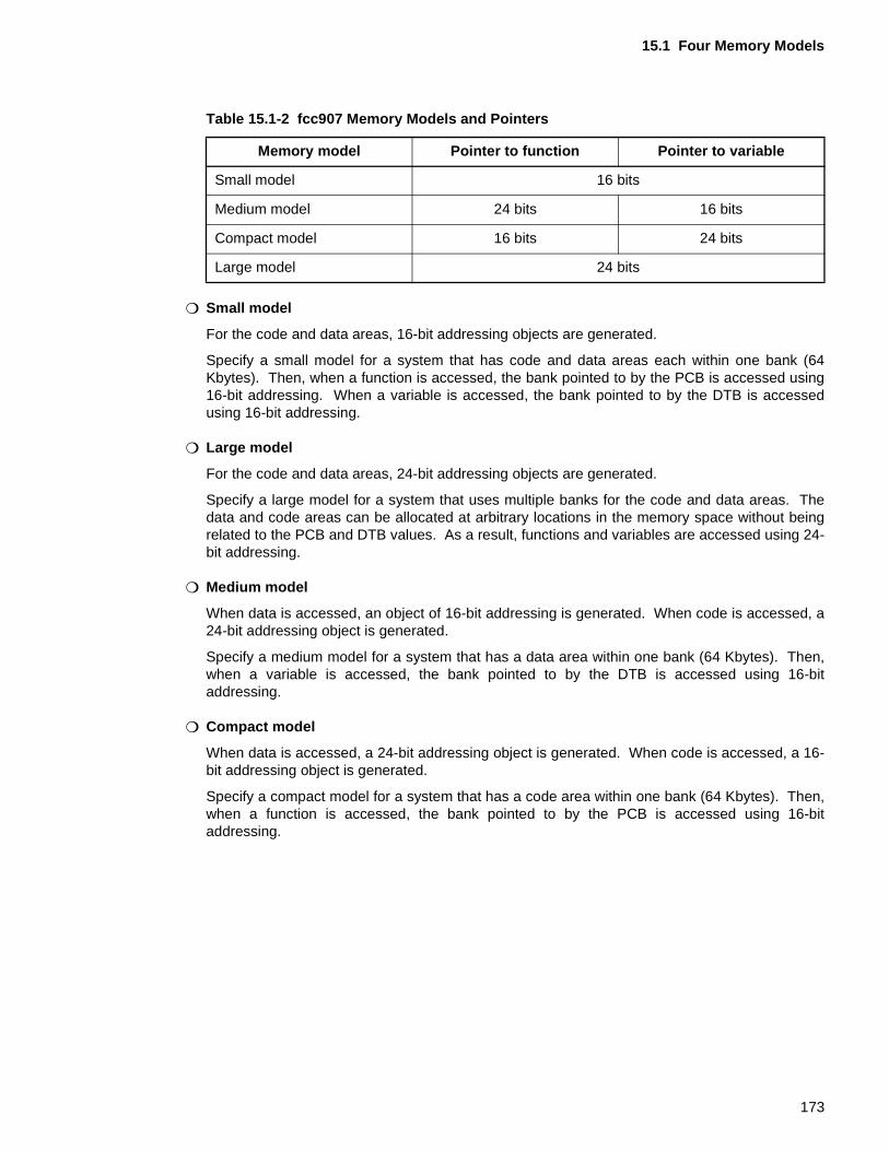
15.1 Four Memory Models
❍ Small model
For the code and data areas, 16-bit addressing objects are generated.
Specify a small model for a system that has code and data areas each within one bank (64Kbytes). Then, when a function is accessed, the bank pointed to by the PCB is accessed using16-bit addressing. When a variable is accessed, the bank pointed to by the DTB is accessedusing 16-bit addressing.
❍ Large model
For the code and data areas, 24-bit addressing objects are generated.
Specify a large model for a system that uses multiple banks for the code and data areas. Thedata and code areas can be allocated at arbitrary locations in the memory space without beingrelated to the PCB and DTB values. As a result, functions and variables are accessed using 24-bit addressing.
❍ Medium model
When data is accessed, an object of 16-bit addressing is generated. When code is accessed, a24-bit addressing object is generated.
Specify a medium model for a system that has a data area within one bank (64 Kbytes). Then,when a variable is accessed, the bank pointed to by the DTB is accessed using 16-bitaddressing.
❍ Compact model
When data is accessed, a 24-bit addressing object is generated. When code is accessed, a 16-bit addressing object is generated.
Specify a compact model for a system that has a code area within one bank (64 Kbytes). Then,when a function is accessed, the bank pointed to by the PCB is accessed using 16-bitaddressing.
Table 15.1-2 fcc907 Memory Models and Pointers
Memory model Pointer to function Pointer to variable
Small model 16 bits
Medium model 24 bits 16 bits
Compact model 16 bits 24 bits
Large model 24 bits
173
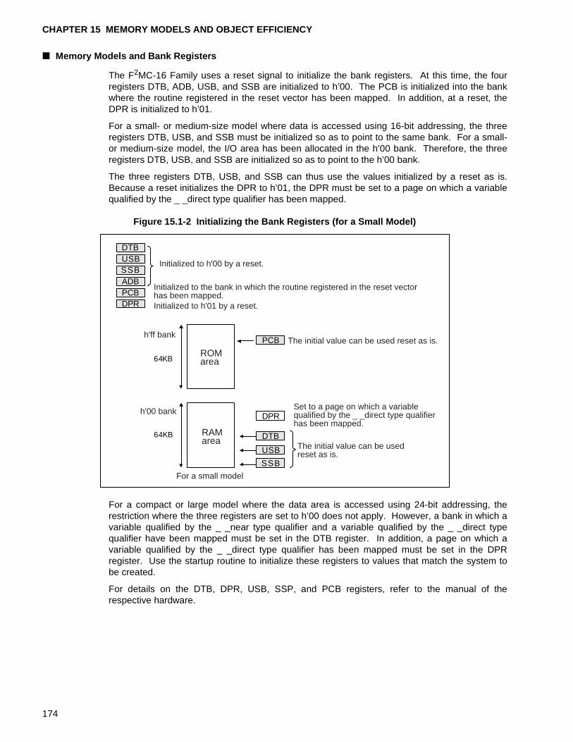
CHAPTER 15 MEMORY MODELS AND OBJECT EFFICIENCY
■ Memory Models and Bank Registers
The F2MC-16 Family uses a reset signal to initialize the bank registers. At this time, the fourregisters DTB, ADB, USB, and SSB are initialized to h’00. The PCB is initialized into the bankwhere the routine registered in the reset vector has been mapped. In addition, at a reset, theDPR is initialized to h’01.
For a small- or medium-size model where data is accessed using 16-bit addressing, the threeregisters DTB, USB, and SSB must be initialized so as to point to the same bank. For a small-or medium-size model, the I/O area has been allocated in the h’00 bank. Therefore, the threeregisters DTB, USB, and SSB are initialized so as to point to the h’00 bank.
The three registers DTB, USB, and SSB can thus use the values initialized by a reset as is.Because a reset initializes the DPR to h’01, the DPR must be set to a page on which a variablequalified by the _ _direct type qualifier has been mapped.
Figure 15.1-2 Initializing the Bank Registers (for a Small Model)
For a compact or large model where the data area is accessed using 24-bit addressing, therestriction where the three registers are set to h’00 does not apply. However, a bank in which avariable qualified by the _ _near type qualifier and a variable qualified by the _ _direct typequalifier have been mapped must be set in the DTB register. In addition, a page on which avariable qualified by the _ _direct type qualifier has been mapped must be set in the DPRregister. Use the startup routine to initialize these registers to values that match the system tobe created.
For details on the DTB, DPR, USB, SSP, and PCB registers, refer to the manual of therespective hardware.
ROMarea
RAMarea
64KB
64KB
h'ff bank
h'00 bank
For a small model
Initialized to h'00 by a reset.
The initial value can be used reset as is.
The initial value can be used reset as is.
Initialized to the bank in which the routine registered in the reset vector has been mapped.
DTB
DPR
SSBADBPCB
PCB
USB
DTB
SSB
USB
DPRSet to a page on which a variable qualified by the _ _direct type qualifier has been mapped.
Initialized to h'01 by a reset.
174
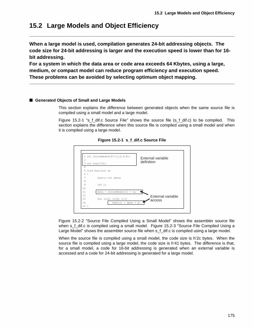
15.2 Large Models and Object Efficiency
15.2 Large Models and Object Efficiency
When a large model is used, compilation generates 24-bit addressing objects. The code size for 24-bit addressing is larger and the execution speed is lower than for 16-bit addressing.For a system in which the data area or code area exceeds 64 Kbytes, using a large, medium, or compact model can reduce program efficiency and execution speed. These problems can be avoided by selecting optimum object mapping.
■ Generated Objects of Small and Large Models
This section explains the difference between generated objects when the same source file iscompiled using a small model and a large model.
Figure 15.2-1 "s_f_dif.c Source File" shows the source file (s_f_dif.c) to be compiled. Thissection explains the difference when this source file is compiled using a small model and whenit is compiled using a large model.
Figure 15.2-1 s_f_dif.c Source File
Figure 15.2-2 "Source File Compiled Using a Small Model" shows the assembler source filewhen s_f_dif.c is compiled using a small model. Figure 15.2-3 "Source File Compiled Using aLarge Model" shows the assembler source file when s_f_dif.c is compiled using a large model.
When the source file is compiled using a small model, the code size is h’2c bytes. When thesource file is compiled using a large model, the code size is h’41 bytes. The difference is that,for a small model, a code for 16-bit addressing is generated when an external variable isaccessed and a code for 24-bit addressing is generated for a large model.
External variable definition
External variable access
175
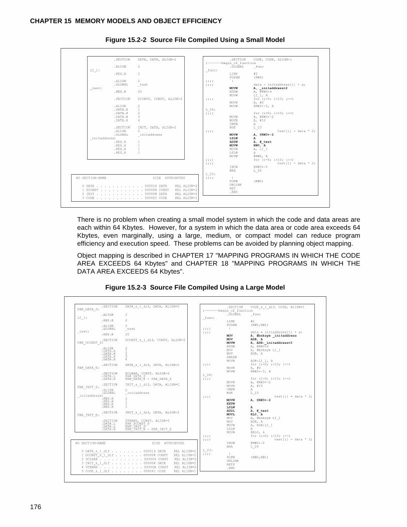
CHAPTER 15 MEMORY MODELS AND OBJECT EFFICIENCY
Figure 15.2-2 Source File Compiled Using a Small Model
There is no problem when creating a small model system in which the code and data areas areeach within 64 Kbytes. However, for a system in which the data area or code area exceeds 64Kbytes, even marginally, using a large, medium, or compact model can reduce programefficiency and execution speed. These problems can be avoided by planning object mapping.
Object mapping is described in CHAPTER 17 "MAPPING PROGRAMS IN WHICH THE CODEAREA EXCEEDS 64 Kbytes" and CHAPTER 18 "MAPPING PROGRAMS IN WHICH THEDATA AREA EXCEEDS 64 Kbytes".
Figure 15.2-3 Source File Compiled Using a Large Model
.SECTION CODE, CODE, ALIGN=1;-------begin_of_function
.GLOBAL _func_func:
LINK #2PUSHW (RW0)
;;;; {;;;; data = initaddress[1] + a;
MOVW A, _initaddress+2ADDW A, @RW3+4MOVW LI_1, A
;;;; for (i=0; i<10; i++)MOVN A, #0MOVW @RW3+-2, A
L_24:;;;; for (i=0; i<10; i++)
MOVW A, @RW3+-2MOVN A, #10CMPW ABGE L_23
;;;; test[i] = data * 2;MOVW A, @RW3+-2LSLW AADDW A, #_testMOVW RW0, AMOVW A, LI_1LSLW AMOVW @RW0, A
;;;; for (i=0; i<10; i++);;;; test[i] = data * 2;
INCW @RW3+-2BRA L_24
L_23:;;;; }
POPW (RW0)UNLINKRET.END
.SECTION DATA, DATA, ALIGN=2
.ALIGN 2LI_1:
.RES.B 2
.ALIGN 2
.GLOBAL _test_test:
.RES.B 20
.SECTION DCONST, CONST, ALIGN=2
.ALIGN 2
.DATA.H 1
.DATA.H 2
.DATA.H 3
.DATA.H 4
.SECTION INIT, DATA, ALIGN=2
.ALIGN 2
.GLOBAL _initaddress_initaddress:
.RES.H 1
.RES.H 1
.RES.H 1
.RES.H 1
NO SECTION-NAME SIZE ATTRIBUTES
0 DATA . . . . . . . . . . . . 000016 DATA REL ALIGN=2
1 DCONST . . . . . . . . . . . 000008 CONST REL ALIGN=2
2 INIT . . . . . . . . . . . . 000008 DATA REL ALIGN=2
3 CODE . . . . . . . . . . . . 00002C CODE REL ALIGN=1
NO SECTION-NAME SIZE ATTRIBUTES
0 DATA_s_l_dif . . . . . . . . 000016 DATA REL ALIGN=2
1 DCONST_s_l_dif . . . . . . . 000008 CONST REL ALIGN=2
2 DCLEAR . . . . . . . . . . . 000006 CONST REL ALIGN=2
3 INIT_s_l_dif . . . . . . . . 000008 DATA REL ALIGN=2
4 DTRANS . . . . . . . . . . . 00000A CONST REL ALIGN=2
5 CODE_s_l_dif . . . . . . . . 000041 CODE REL ALIGN=1
.SECTION DATA_s_l_dif, DATA, ALIGN=2FAR_DATA_S:
.ALIGN 2LI_1:
.RES.B 2
.ALIGN 2
.GLOBAL _test_test:
.RES.B 20
.SECTION DCONST_s_l_dif, CONST, ALIGN=2FAR_DCONST_S:
.ALIGN 2
.DATA.H 1
.DATA.H 2
.DATA.H 3
.DATA.H 4
.SECTION DATA_s_l_dif, DATA, ALIGN=2FAR_DATA_E:
.SECTION DCLEAR, CONST, ALIGN=2
.DATA.L FAR_DATA_S
.DATA.H FAR_DATA_E - FAR_DATA_S
.SECTION INIT_s_l_dif, DATA, ALIGN=2FAR_INIT_S:
.ALIGN 2
.GLOBAL _initaddress_initaddress:
.RES.H 1
.RES.H 1
.RES.H 1
.RES.H 1
.SECTION INIT_s_l_dif, DATA, ALIGN=2FAR_INIT_E:
.SECTION DTRANS, CONST, ALIGN=2
.DATA.L FAR_DCONST_S
.DATA.L FAR_INIT_S
.DATA.H FAR_INIT_E - FAR_INIT_S
.SECTION CODE_s_l_dif, CODE, ALIGN=1;-------begin_of_function
.GLOBAL _func_func:
LINK #2PUSHW (RW0,RW1)
;;;; {;;;; data = initaddress[1] + a;
MOV A, #bnksym _initaddressMOV ADB, AMOVW A, ADB:_initaddress+2ADDW A, @RW3+6MOV A, #bnksym LI_1MOV ADB, ASWAPWMOVW ADB:LI_1, A
;;;; for (i=0; i<10; i++)MOVN A, #0MOVW @RW3+-2, A
L_24:;;;; for (i=0; i<10; i++)
MOVW A, @RW3+-2MOVN A, #10CMPW ABGE L_23
;;;; test[i] = data * 2;MOVW A, @RW3+-2EXTWLSLW AADDL A, #_testMOVL RL0, AMOV A, #bnksym LI_1MOV ADB, AMOVW A, ADB:LI_1LSLW AMOVW @RL0, A
;;;; for (i=0; i<10; i++);;;; test[i] = data * 2;
INCW @RW3+-2BRA L_24
L_23:;;;; }
POPW (RW0,RW1)UNLINKRETP.END
176
CHAPTER 16 MAPPING VARIABLES QUALIFIED WITH THE TYPE QUALIFIER CONST
This chapter describes mapping of variables that have been qualified by the const type
qualifier. The F 2MC-16L/LX/F series has a function referred to as the mirror ROM function. For small and medium models, this function enables variables mapped in the ROM area to be accessed using 16-bit addressing.
16.1 "Using the Mirror ROM Function and const Type Qualifier"
16.2 "const Type Qualifier When the Mirror ROM Function Cannot Be Used"
177
CHAPTER 16 MAPPING VARIABLES QUALIFIED WITH THE TYPE QUALIFIER CONST
16.1 Using the Mirror ROM Function and const Type Qualifier
This section provides notes on mapping variables qualified by the const type qualifier for hardware that supports the mirror ROM function.By mapping variables in the areas defined for the hardware, variables in the ROM area can be accessed using 16-bit addressing.
■ What Is the Mirror ROM Function?
The F2MC-16L/LX/F series has a function referred to as the mirror ROM function. When areadefined in the h’00 bank is accessed using 16-bit addressing, the mirror ROM functionautomatically accesses the same area in the ROM area of the h’ff bank using 16-bit addressing.
As a result, a variable qualified by the const type qualifier that has been mapped in the ROMarea can be accessed using 16-bit addressing in the same way as a standard variable mappedin the h’00 bank.
Figure 16.1-1 "Accessing Variables Qualified by the const Type Qualifier for Hardware ThatSupports the Mirror ROM Function" shows an access image of variables qualified by a consttype qualifier for hardware that supports the mirror ROM function.
Sections 16.1.1 "const Type Qualifier and Mirror ROM Function for Small and Medium Models"and 16.1.2 "const Type Qualifier and Mirror ROM Function for Compact and Large Models"provide notes on each memory model.
The mirror ROM function depends on the hardware of the F2MC-16L/LX/F series. For details,refer to the hardware manual.
Figure 16.1-1 Accessing Variables Qualified by the const Type Qualifier for Hardware That Supports the Mirror ROM Function
I/O area
RAM area
ROM area h'ff bank image
Area that can be accessed from the h'00 bank.
Area that cannot be accessed from the h'00 bank.
Single chip mode (For the MB90678)
h'ff bank ROM area 64 Kbytes
h'00 bank 64 Kbytes
PCB
DTB,SSB,USB
When using a chip that has the mirror ROM function such as the MB90678
Accessing addresses h'4000 to h'ffff in the h'00 bank accesses the same addresses in the h'ff bank. Memory is not present at addresses h'4000 to h'ffff in the h'00 bank. However, the system operates as if the h'00 bank were being accessed. Addresses h'0000 to h'3fff in the h'ff bank cannot be accessed from the h'00 bank.
The addresses of the areas in the h'00 bank depend on the chip.
178
16.1 Using the Mirror ROM Function and const Type Qualifier
16.1.1 const Type Qualifier and Mirror ROM Function for Small and Medium Models
For small and medium models in which the data area is restricted to within 64 Kbytes, variables are accessed using 16-bit addressing on the premise that the variables are mapped in the bank pointed to by the DTB.The mirror ROM function enables variables that are mapped in the h’ff bank to be accessed using 16-bit addressing.
■ Allocating Sections of Initialized Variables
For small and medium models, the data area that can be used is restricted to one bank within64 Kbytes. As a result, variables are accessed using 16-bit addressing on the premise that thevariables are in the bank pointed to by the DTB.
Figure 16.1-2 "Output Sections and Their Allocation for Small and Medium Models" shows therelationship between the output sections of variables for which initial values are specified andtheir allocation in memory for small and medium models.
Figure 16.1-2 Output Sections and Their Allocation for Small and Medium Models
For small and medium models, a variable qualified by the const type qualifier is output to theCONST section. At linkage, this CONST section is allocated in the ROM area of the h’ff bank.Normally, a CONST section present somewhere other than the bank pointed to by the DTBcannot be accessed using 16-bit addressing. If hardware that supports the mirror ROM functionis used, however, a variable in the CONST section allocated at a defined location in the ROMarea can be accessed using 16-bit addressing.
Variable qualified by the const type qualifier Initialized variable
The area CONST of a variable qualified by the const type qualifier is allocated in the ROM area.
DCONST
INIT
CONSTROM area
RAM area
LinkINITCONST DCONST
When the variable is accessed, the ROM area is accessed directly. The initial value area DCONST is allocated in the ROM area. The area INIT that is accessed at execution is allocated in the RAM area. For an initialized variable, the total size of the required ROM and RAM areas must be twice the size of the defined variable.
The startup routine transfers the initial value in the ROM area to the variable area in the RAM area.
179
CHAPTER 16 MAPPING VARIABLES QUALIFIED WITH THE TYPE QUALIFIER CONST
■ Notes on Using the Mirror ROM Function
The areas at which variables in the h’ff bank can be accessed by the mirror ROM function using
16-bit addressing depend on the hardware of the F2MC-16L/LX/F series. Table 16.1-1 "Scopeof Use of the Mirror ROM Function" lists the areas supported by the MB90670 series.
Variables mapped within the range listed above can be accessed using 16-bit addressing in thesame way as accessing other variables mapped by a function in the h’00 bank. This is possiblebecause, when addresses h’0000 to h’ffff, h’8000 to h’ffff, or h’c000 to h’fff in the h’00 bank areaccessed, the CPU unconditionally accesses the same area in the h’ff bank. Therefore, whenthe area CONST section of a variable qualified by the const type qualifier is allocated within therange listed above, the variable area in the ROM area can be accessed directly using 16-bitaddressing without using the _ _far type qualifier. As a result, using the startup routine totransfer the initial values from the ROM area to the RAM area can be omitted for a variablequalified by the const type qualifier. Because variables qualified by the const type qualifier arepresent in the ROM area, initial values can of course be set at definition but the values cannotbe changed at execution.
Figure 16.1-3 "Using the Mirror ROM Function and Allocating Areas of a Variable Qualified bythe const Type Qualifier (for a Small Model)" shows an example of allocating areas of a variablequalified by the const type qualifier for a small model.
Figure 16.1-3 Using the Mirror ROM Function and Allocating Areas of a Variable Qualified by the const Type Qualifier (for a Small Model)
<Notes>
Note the following points regarding use of the mirror ROM function:
- Map variables qualified by the const type qualifier up to address h’ff53 in the h’ff bank.
Table 16.1-1 Scope of Use of the Mirror ROM Function
Product MB90671 MB90672 MB90673 MB90P673
Starting address h’ffc000 h’ff8000 h’ff4000 h’ff4000
Ending address h’ffffff h’ffffff h’ffffff h’ffffff
I/O area
Register bank
DATA
INIT
DIRDATA
DIRINIT
STACK
CODE
DCONST
DIRCONST
CONST
INTVECT
DTB,SSB,USB
DPR
PCB
RAM area
ROM area
The area CONST section of a variable qualified by the const type qualifier is present in the h'ff bank.
When this area in the h'00 bank is accessed, the CONST section in the h'ff bank is accessed unconditionally. As a result, the value need not be transferred from the ROM area to the RAM area. In addition, because the variable can be accessed using 16-bit addressing, the code is smaller than the definition that accompanies the _ _far type qualifier for accessing outside of the bank.
The initial value in the ROM area is transferred to the variable area in the RAM area.
@ -AL 0
@ -ro ROM_AREA=0xFF0000/0xFFFFFF
@ -ra RAM_AREA=0x000190/0x000CFF
@ -sc DATA/BYTE+INIT/BYTE+DIRDATA/PAGE+DIRINIT/WORD
+STACK/BYTE=RAM_AREA
@ -sc CODE/BYTE+DCONST/BYTE+DIRCONST/BYTE=ROM_AREA
@ -sc CONST/const/BYTE=0xFF4000
@ -rg 0
@ -m :¥softune¥ ¥CONST_**¥LST¥CONST.mp1
@ -pl 60
@ -pw 132
@ -alin :¥softune¥*¥CONST_**¥LST¥
@ -alout :¥softune¥*¥CONST_**¥LST¥
@ -na
@ -Xals
@ -Xalr
@ -w 1
@ -g
@ -cwno
@ -a
@ -cpu MB90678
@ -o *:¥softune¥*¥CONST_**¥ABS¥CONST_**.abs
180
16.1 Using the Mirror ROM Function and const Type Qualifier
Interrupt vectors are mapped between addresses h’ff54 and h’ffff in the h’ff bank. If avariable is mapped in this area, interrupt operations will be unpredictable.
- Allocate the area for variables qualified by the const type qualifier so that the area isaccommodated in the area determined for each chip in the h’ff bank. If a variable exceedsthe area, accessing using 16-bit addressing will not be possible.
- Do not allocate variable area or a stack in the area determined for each chip such asaddresses h’4000 to h’ffff or h’8000 to h’ffff in the h’00 bank. Because the h’ff bank isaccessed, the value of a variable or stack in this area will be unpredictable.
181
CHAPTER 16 MAPPING VARIABLES QUALIFIED WITH THE TYPE QUALIFIER CONST
16.1.2 const Type Qualifier and Mirror ROM Function for Compact and Large Models
For compact and large models, variables are accessed using 24-bit addressing. Therefore, the restriction dependent on the setting of the DTB register for small and compact models does not apply.
■ Allocating Sections of Initialized Variables
For compact and large models, the variable area can be allocated in multiple banks. Thevariables are always accessed using 24-bit addressing. Therefore, the restriction dependent onthe setting of the DTB register for small and compact models does not apply. The bank pointedto by the DTB register is accessed using 16-bit addressing only when a variable qualified by the_ _near type qualifier is accessed.
When defining a variable qualified by the _ _const type qualifier, specify the _ _const typequalifier only, or specify the _ _const type qualifier and the _ _far type qualifier. For compactand large models, a variable qualified by the _ _const type qualifier is output to a section called"CONST_module name."
Figure 16.1-4 "Output Sections and Their Allocation for Compact and Large Models" shows therelationship between the output sections of variables for which initial values are specified andtheir allocation in memory for compact and large models.
Figure 16.1-4 Output Sections and Their Allocation for Compact and Large Models
For compact and large models, a variable qualified by the const type qualifier is output to asection called "CONST_module name." At linkage, this CONST_module section is allocated inthe ROM area. Because a variable is accessed using 24-bit addressing, the ROM area can beaccessed directly.
Variable qualified by the const type qualifier Initialized variable
ROM area
RAM area
LinkINIT_* DCONST_*
CONST_*
DCONST_*
INIT_*
CONST_*
The initial value area DCONST_* is allocated in the ROM area. The area INIT_* that is accessed at execution is allocated in the RAM area. For an initialized variable, the total size of the required ROM and RAM areas must be twice the size of the defined variable.
The startup routine transfers the initial value in the ROM area to the variable area in the RAM area.
The area CONST_* of a variable qualified by the const type qualifier is allocated in the ROM area. When the variable is accessed, the ROM area is accessed directly.
Note: The asterisk (*) in the section name indicates the module name.
182
16.1 Using the Mirror ROM Function and const Type Qualifier
■ Notes on Using the Mirror ROM Function
The areas where variables in the h’ff bank can be accessed by the mirror ROM function using
16-bit addressing depend on the hardware of the F2MC-16L/LX/F series.
For compact and large models, specify the const type and _ _near type qualifiers when themirror ROM function is used to access a variable qualified by the const type qualifier using 16-bit addressing. The variable will then be output to the CONST section that can be accessedwhen the bank pointed to by the DTB register is accessed using 16-bit addressing. At linkage,allocate this CONST section in an area supported by the mirror ROM function.
Figure 16.1-5 Using the Mirror ROM Function and Allocating Areas of a Variable Qualified by the const Type Qualifier (for a Large Model)
I/O area
Register bank
DIRDATA
DIRINIT
STACK
CODE_main
DCONST_main
DIRCONST
CONST
INTVECT
DTB
DPR
PCB
CODE_sub
DCONST_sub
DATA_sub
INIT_sub
DATA_main
INIT_main
SSB,USB
ROM area
RAM area
When this area in the h'00 bank is accessed, the CONST section in the h'ff bank is accessed unconditionally. As a result, the value need not be transferred from the ROM area to the RAM area. In addition, specifying the _ _near type qualifier enables the variable to be accessed using 16-bit addressing.
The area CONST section of a variable qualified by the const type qualifier is present in the h'ff bank.
The initial value in the ROM area is transferred to the variable area in the RAM area.
@ -AL 0@ -ro ROM_AREA3=0xFD0000/0xFDFFFF@ -ro ROM_AREA2=0xFE0000/0xFEFFFF@ -ro ROM_AREA1=0xFF0000/0xFFFFFF@ -ra RAM_AREA1=0x000190/0x000CFF@ -ra RAM_AREA2=0x010000/0x01FFFF@ -ra RAM_AREA3=0x020000/0x02FFFF@ -ra RAM_AREA4=0x030000/0x03FFFF@ -sc DIRDATA/dir/PAGE+DIRINIT/dir/BYTE=RAM_AREA1@ -sc DATA_main/data/BYTE+INIT_main/data/BYTE=RAM_AREA2@ -sc DATA_sub/data/BYTE+INIT_sub/data/BYTE=RAM_AREA3@ -sc STACK/BYTE=RAM_AREA4@ -sc CODE_sub/code/BYTE+DCONST_sub/const/BYTE=ROM_AREA3@ -sc CODE_main/code/BYTE+DCONST_main/const/BYTE=ROM_AREA2@ -sc DIRCONST/dirconst/BYTE=ROM_AREA1@ -sc CONST/BYTE=0xFF4000@ -m *:¥*¥LST¥for_text.mp1@ -pl 60@ -pw 132@ -alin *:¥*¥for_text¥LST¥@ -alout *:¥*¥for_text¥LST¥@ -na@ -Xals@ -Xalr@ -w 1@ -g@ -cwno@ -a@ -cpu MB90678@ -o *:¥*¥for_text¥ABS¥for_text.abs-Xdof
h�ff ffff
h�ff ff54
h�ff 4000
h�00 4000
h�00 0000
h�00 0180
h�ff 0000
h�fe 0000
h�fd 0000
h�03 0000
h�02 0000
h�01 0000
183
CHAPTER 16 MAPPING VARIABLES QUALIFIED WITH THE TYPE QUALIFIER CONST
16.2 const Type Qualifier When the Mirror ROM Function Cannot Be Used
This section provides notes on mapping variables qualified by the const type qualifier for hardware that does not support the mirror ROM function.The -ramconst option can be specified to output a section allocated to the ROM and RAM areas. In addition, specifying the const type and _ _far type qualifiers enables the variable area in the ROM area to be accessed directly using 24-bit addressing.
■ Mapping Variables Qualified by the const Type Qualifier for Hardware That Does Not Support the Mirror ROM Function
The F2MC-16L/LX/F series includes hardware that does not support the mirror ROM function.For systems that use such hardware, the ROM area in the h’ff bank cannot be accessed using16-bit addressing. This applies to small and compact models where the data area is accessedusing 16-bit addressing.
For these types of systems, the following two methods are available for mapping variablesqualified by the const type qualifier:
• Specify the -ramconst option at compilation.
• Specify the const type and _ _far type qualifiers at definition.
Sections 16.2.1 "Mapping Variables Qualified by the const Type Qualifier to RAM Area" and16.2.2 "Specifying the const Type and _ _far Type Qualifiers at Definition" describe these twomethods.
For compact and large models where the data area is accessed using 24-bit addressing,because the variable area in the ROM area can be accessed directly, the above problem doesnot occur.
184
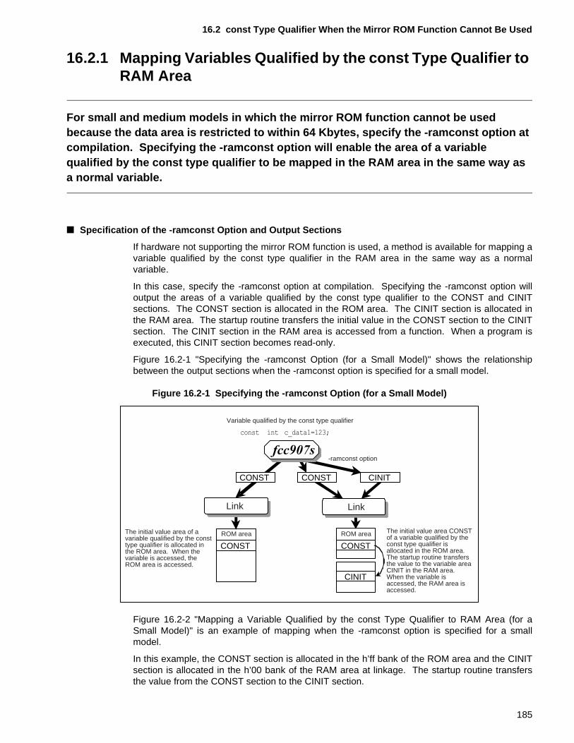
16.2 const Type Qualifier When the Mirror ROM Function Cannot Be Used
16.2.1 Mapping Variables Qualified by the const Type Qualifier to RAM Area
For small and medium models in which the mirror ROM function cannot be used because the data area is restricted to within 64 Kbytes, specify the -ramconst option at compilation. Specifying the -ramconst option will enable the area of a variable qualified by the const type qualifier to be mapped in the RAM area in the same way as a normal variable.
■ Specification of the -ramconst Option and Output Sections
If hardware not supporting the mirror ROM function is used, a method is available for mapping avariable qualified by the const type qualifier in the RAM area in the same way as a normalvariable.
In this case, specify the -ramconst option at compilation. Specifying the -ramconst option willoutput the areas of a variable qualified by the const type qualifier to the CONST and CINITsections. The CONST section is allocated in the ROM area. The CINIT section is allocated inthe RAM area. The startup routine transfers the initial value in the CONST section to the CINITsection. The CINIT section in the RAM area is accessed from a function. When a program isexecuted, this CINIT section becomes read-only.
Figure 16.2-1 "Specifying the -ramconst Option (for a Small Model)" shows the relationshipbetween the output sections when the -ramconst option is specified for a small model.
Figure 16.2-1 Specifying the -ramconst Option (for a Small Model)
Figure 16.2-2 "Mapping a Variable Qualified by the const Type Qualifier to RAM Area (for aSmall Model)" is an example of mapping when the -ramconst option is specified for a smallmodel.
In this example, the CONST section is allocated in the h’ff bank of the ROM area and the CINITsection is allocated in the h’00 bank of the RAM area at linkage. The startup routine transfersthe value from the CONST section to the CINIT section.
Variable qualified by the const type qualifier
CONST
ROM area
Link
CONST
ROM area
Link
CINIT
-ramconst option
CONST CONST CINIT
The initial value area of a variable qualified by the const type qualifier is allocated in the ROM area. When the variable is accessed, the ROM area is accessed.
The initial value area CONST of a variable qualified by the const type qualifier is allocated in the ROM area. The startup routine transfers the value to the variable area CINIT in the RAM area. When the variable is accessed, the RAM area is accessed.
185
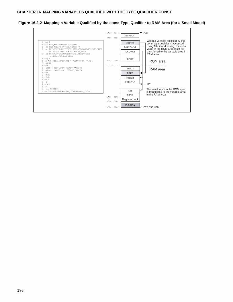
CHAPTER 16 MAPPING VARIABLES QUALIFIED WITH THE TYPE QUALIFIER CONST
Figure 16.2-2 Mapping a Variable Qualified by the const Type Qualifier to RAM Area (for a Small Model)
I/O area
Register bank
DATA
INIT
DIRDATA
DIRINIT
CINIT
CODE
DCONST
DIRCONST
CONST
INTVECT
DTB,SSB,USB
DPR
PCB
STACK
ROM area
RAM area
When a variable qualified by the const type qualifier is accessed using 16-bit addressing, the initial value in the ROM area must be transferred to the variable area in RAM area.
The initial value in the ROM area is transferred to the variable area in the RAM area.
h�ff ffff
h�ff ff54
h�ff 0000
h�00 0000
h�00 0180
@ -AL 0
@ -ro ROM_AREA=0xFF0000/0xFFFFFF@ -ra RAM_AREA=0x000190/0x000CFF@ -sc DATA/BYTE+INIT/BYTE+DIRDATA/PAGE+DIRINIT/WORD
+CINIT/BYTE+STACK/BYTE=RAM_AREA
@ -sc CODE/BYTE+DCONST/BYTE+DIRCONST/BYTE+CONST/BYTE=ROM_AREA
@ -rg 0
@ -m *:¥softune¥*¥CONST_**¥LST¥CONST_**.mp1@ -pl 60@ -pw 132@ -alin *:¥softune¥*¥CONST_**¥LST¥
@ -alout *:¥softune¥*¥CONST_*¥LST¥@ -na@ -Xals
@ -Xalr@ -w 1@ -g
@ -cwno@ -a@ -cpu MB90678@ -o *:¥softune¥*¥CONST_*¥ABS¥CONST_*.abs
h�00 0190
186
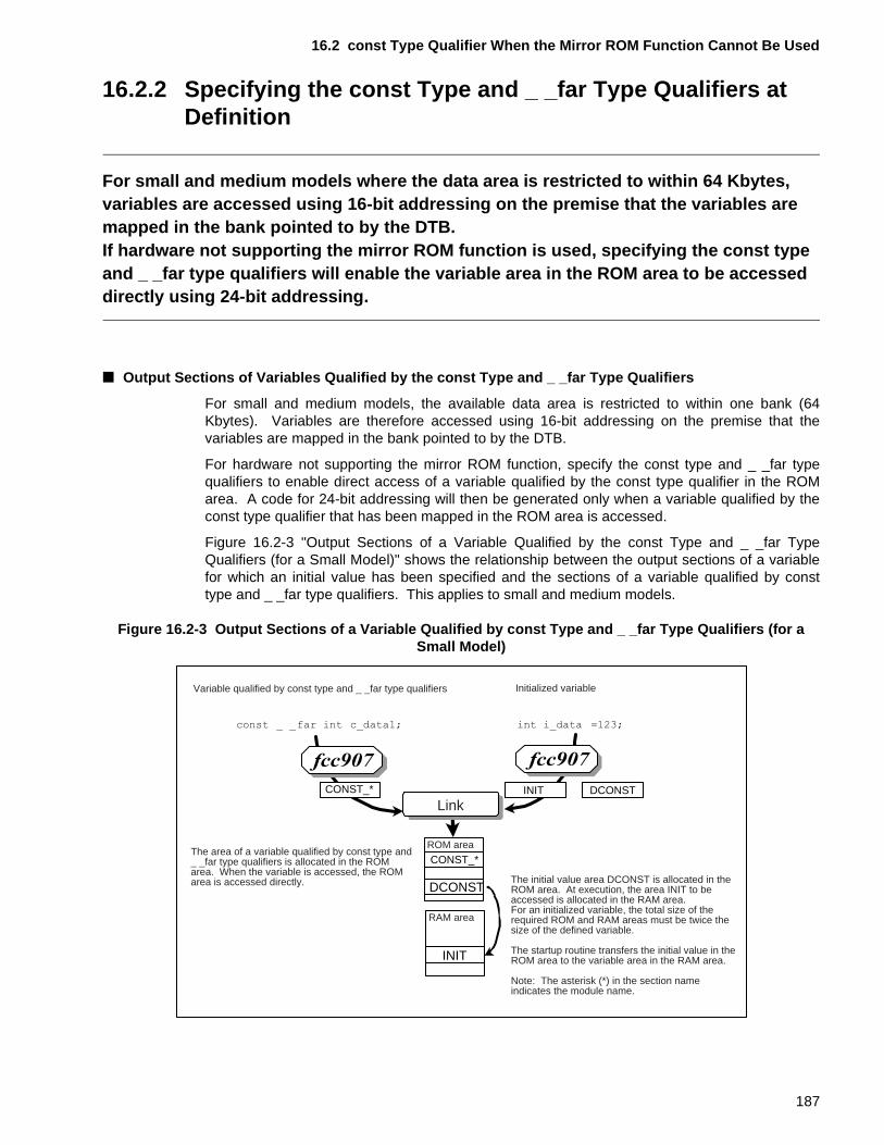
16.2 const Type Qualifier When the Mirror ROM Function Cannot Be Used
16.2.2 Specifying the const Type and _ _far Type Qualifiers at Definition
For small and medium models where the data area is restricted to within 64 Kbytes, variables are accessed using 16-bit addressing on the premise that the variables are mapped in the bank pointed to by the DTB.If hardware not supporting the mirror ROM function is used, specifying the const type and _ _far type qualifiers will enable the variable area in the ROM area to be accessed directly using 24-bit addressing.
■ Output Sections of Variables Qualified by the const Type and _ _far Type Qualifiers
For small and medium models, the available data area is restricted to within one bank (64Kbytes). Variables are therefore accessed using 16-bit addressing on the premise that thevariables are mapped in the bank pointed to by the DTB.
For hardware not supporting the mirror ROM function, specify the const type and _ _far typequalifiers to enable direct access of a variable qualified by the const type qualifier in the ROMarea. A code for 24-bit addressing will then be generated only when a variable qualified by theconst type qualifier that has been mapped in the ROM area is accessed.
Figure 16.2-3 "Output Sections of a Variable Qualified by the const Type and _ _far TypeQualifiers (for a Small Model)" shows the relationship between the output sections of a variablefor which an initial value has been specified and the sections of a variable qualified by consttype and _ _far type qualifiers. This applies to small and medium models.
Figure 16.2-3 Output Sections of a Variable Qualified by const Type and _ _far Type Qualifiers (for a Small Model)
Variable qualified by const type and _ _far type qualifiers
DCONST
INIT
CONST_*ROM area
RAM area
Link INITCONST_* DCONST
Initialized variable
The area of a variable qualified by const type and _ _far type qualifiers is allocated in the ROM area. When the variable is accessed, the ROM area is accessed directly. The initial value area DCONST is allocated in the
ROM area. At execution, the area INIT to be accessed is allocated in the RAM area. For an initialized variable, the total size of the required ROM and RAM areas must be twice the size of the defined variable.
The startup routine transfers the initial value in the ROM area to the variable area in the RAM area.
Note: The asterisk (*) in the section name indicates the module name.
187
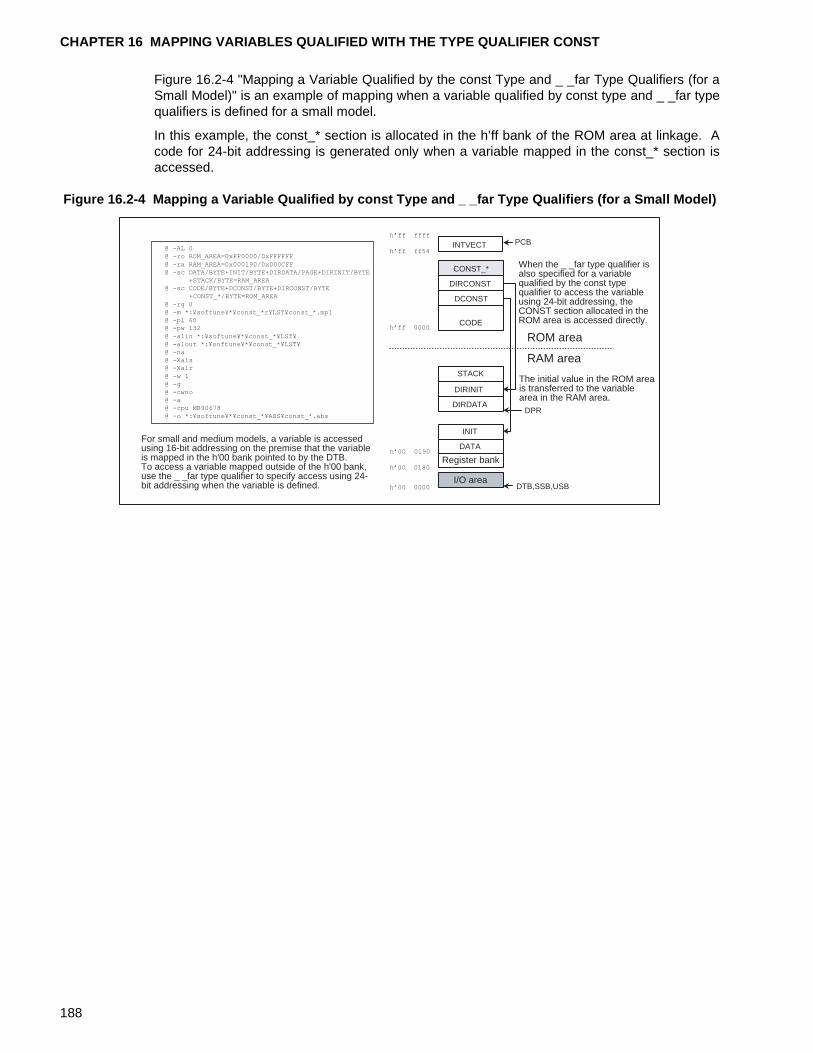
CHAPTER 16 MAPPING VARIABLES QUALIFIED WITH THE TYPE QUALIFIER CONST
Figure 16.2-4 "Mapping a Variable Qualified by the const Type and _ _far Type Qualifiers (for aSmall Model)" is an example of mapping when a variable qualified by const type and _ _far typequalifiers is defined for a small model.
In this example, the const_* section is allocated in the h’ff bank of the ROM area at linkage. Acode for 24-bit addressing is generated only when a variable mapped in the const_* section isaccessed.
Figure 16.2-4 Mapping a Variable Qualified by const Type and _ _far Type Qualifiers (for a Small Model)
I/O area
Register bank
DATA
INIT
DIRDATA
DIRINIT
STACK
CODE
DCONST
DIRCONST
CONST_*
INTVECT
DTB,SSB,USB
DPR
PCB
ROM area
RAM area
For small and medium models, a variable is accessed using 16-bit addressing on the premise that the variable is mapped in the h'00 bank pointed to by the DTB. To access a variable mapped outside of the h'00 bank, use the _ _far type qualifier to specify access using 24-bit addressing when the variable is defined.
When the _ _far type qualifier is also specified for a variable qualified by the const type qualifier to access the variable using 24-bit addressing, the CONST section allocated in the ROM area is accessed directly.
The initial value in the ROM area is transferred to the variable area in the RAM area.
h�ff ffff
h�ff ff54
h�ff 0000
h�00 0000
h�00 0180
@ -AL 0@ -ro ROM_AREA=0xFF0000/0xFFFFFF
@ -ra RAM_AREA=0x000190/0x000CFF@ -sc DATA/BYTE+INIT/BYTE+DIRDATA/PAGE+DIRINIT/BYTE
+STACK/BYTE=RAM_AREA@ -sc CODE/BYTE+DCONST/BYTE+DIRCONST/BYTE
+CONST_*/BYTE=ROM_AREA
@ -rg 0@ -m *:¥softune¥*¥const_*r¥LST¥const_*.mp1@ -pl 60@ -pw 132
@ -alin *:¥softune¥*¥const_*¥LST¥@ -alout *:¥softune¥*¥const_*¥LST¥@ -na@ -Xals@ -Xalr
@ -w 1@ -g@ -cwno@ -a@ -cpu MB90678@ -o *:¥softune¥*¥const_*¥ABS¥const_*.abs
h�00 0190
188
CHAPTER 17 MAPPING PROGRAMS IN WHICH THE CODE AREA EXCEEDS 64 Kbytes
This chapter describes how to map programs in which the code area of the program to be created exceeds 64 Kbytes.For a system in which the code area exceeds 64 Kbytes, it is recommended that a small or compact model be used and that the _ _far type qualifier be specified in the functions.
17.1 "Functions Calls of Programs in Which the Code Area Exceeds 64 Kbytes"
17.2 "Using Calls For Functions Qualified by the _ _far Type Qualifier"
17.3 "Mapping Functions Qualified by the _ _far Type Qualifier"
17.4 "Using Calls for Functions Qualified by the _ _near Type Qualifier"
17.5 "Mapping Functions Qualified by the _ _near Type Qualifier"
189
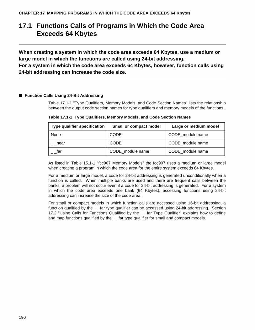
CHAPTER 17 MAPPING PROGRAMS IN WHICH THE CODE AREA EXCEEDS 64 Kbytes
17.1 Functions Calls of Programs in Which the Code Area Exceeds 64 Kbytes
When creating a system in which the code area exceeds 64 Kbytes, use a medium or large model in which the functions are called using 24-bit addressing.For a system in which the code area exceeds 64 Kbytes, however, function calls using 24-bit addressing can increase the code size.
■ Function Calls Using 24-Bit Addressing
Table 17.1-1 "Type Qualifiers, Memory Models, and Code Section Names" lists the relationshipbetween the output code section names for type qualifiers and memory models of the functions.
As listed in Table 15.1-1 "fcc907 Memory Models" the fcc907 uses a medium or large modelwhen creating a program in which the code area for the entire system exceeds 64 Kbytes.
For a medium or large model, a code for 24-bit addressing is generated unconditionally when afunction is called. When multiple banks are used and there are frequent calls between thebanks, a problem will not occur even if a code for 24-bit addressing is generated. For a systemin which the code area exceeds one bank (64 Kbytes), accessing functions using 24-bitaddressing can increase the size of the code area.
For small or compact models in which function calls are accessed using 16-bit addressing, afunction qualified by the _ _far type qualifier can be accessed using 24-bit addressing. Section17.2 "Using Calls for Functions Qualified by the _ _far Type Qualifier" explains how to defineand map functions qualified by the _ _far type qualifier for small and compact models.
Table 17.1-1 Type Qualifiers, Memory Models, and Code Section Names
Type qualifier specification Small or compact model Large or medium model
None CODE CODE_module name
_ _near CODE CODE_module name
_ _far CODE_module name CODE_module name
190
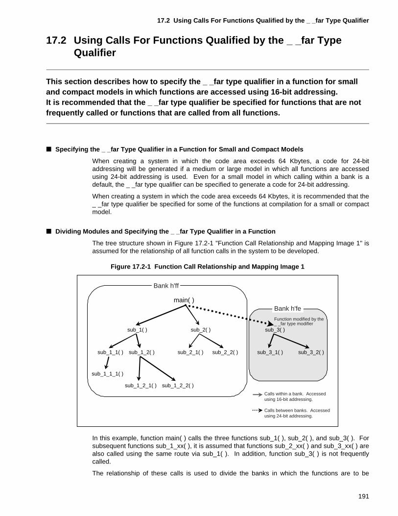
17.2 Using Calls For Functions Qualified by the _ _far Type Qualifier
17.2 Using Calls For Functions Qualified by the _ _far Type Qualifier
This section describes how to specify the _ _far type qualifier in a function for small and compact models in which functions are accessed using 16-bit addressing.It is recommended that the _ _far type qualifier be specified for functions that are not frequently called or functions that are called from all functions.
■ Specifying the _ _far Type Qualifier in a Function for Small and Compact Models
When creating a system in which the code area exceeds 64 Kbytes, a code for 24-bitaddressing will be generated if a medium or large model in which all functions are accessedusing 24-bit addressing is used. Even for a small model in which calling within a bank is adefault, the _ _far type qualifier can be specified to generate a code for 24-bit addressing.
When creating a system in which the code area exceeds 64 Kbytes, it is recommended that the_ _far type qualifier be specified for some of the functions at compilation for a small or compactmodel.
■ Dividing Modules and Specifying the _ _far Type Qualifier in a Function
The tree structure shown in Figure 17.2-1 "Function Call Relationship and Mapping Image 1" isassumed for the relationship of all function calls in the system to be developed.
Figure 17.2-1 Function Call Relationship and Mapping Image 1
In this example, function main( ) calls the three functions sub_1( ), sub_2( ), and sub_3( ). Forsubsequent functions sub_1_xx( ), it is assumed that functions sub_2_xx( ) and sub_3_xx( ) arealso called using the same route via sub_1( ). In addition, function sub_3( ) is not frequentlycalled.
The relationship of these calls is used to divide the banks in which the functions are to be
main( )
sub_1( ) sub_2( ) sub_3( )
sub_1_1( )
sub_1_1_1( )
sub_1_2( ) sub_2_1( ) sub_2_2( )
sub_1_2_1( ) sub_1_2_2( )
sub_3_1( ) sub_3_2( )
Bank h'ff
Bank h'fe
Function modified by the _ _far type modifier
Calls within a bank. Accessed using 16-bit addressing.
Calls between banks. Accessed using 24-bit addressing.
191
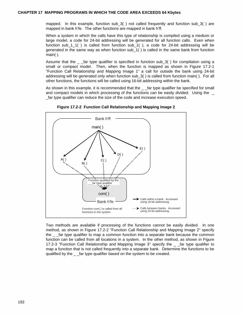
CHAPTER 17 MAPPING PROGRAMS IN WHICH THE CODE AREA EXCEEDS 64 Kbytes
mapped. In this example, function sub_3( ) not called frequently and function sub_3( ) aremapped in bank h’fe. The other functions are mapped in bank h’ff.
When a system in which the calls have this type of relationship is compiled using a medium orlarge model, a code for 24-bit addressing will be generated for all function calls. Even whenfunction sub_1_1( ) is called from function sub_1( ), a code for 24-bit addressing will begenerated in the same way as when function sub_1( ) is called in the same bank from functionmain( ).
Assume that the _ _far type qualifier is specified in function sub_3( ) for compilation using asmall or compact model. Then, when the function is mapped as shown in Figure 17.2-1"Function Call Relationship and Mapping Image 1" a call for outside the bank using 24-bitaddressing will be generated only when function sub_3( ) is called from function main( ). For allother functions, the functions will be called using 16-bit addressing within the bank.
As shown in this example, it is recommended that the _ _far type qualifier be specified for smalland compact models in which processing of the functions can be easily divided. Using the __far type qualifier can reduce the size of the code and increase execution speed.
Figure 17.2-2 Function Call Relationship and Mapping Image 2
Two methods are available if processing of the functions cannot be easily divided. In onemethod, as shown in Figure 17.2-2 "Function Call Relationship and Mapping Image 2" specifythe _ _far type qualifier to map a common function into a separate bank because the commonfunction can be called from all locations in a system. In the other method, as shown in Figure17.2-3 "Function Call Relationship and Mapping Image 3" specify the _ _far type qualifier tomap a function that is not called frequently into a separate bank. Determine the functions to bequalified by the _ _far type qualifier based on the system to be created.
main( )
A( ) C( )
D( )
Bank h'ff
Bank h'fe
B( )
E( )
com( )
Function qualified by the_ _far type qualifier
Function com( ) is called from all functions in the system.
Calls within a bank. Accessed using 16-bit addressing.
Calls between banks. Accessed using 24-bit addressing.
192
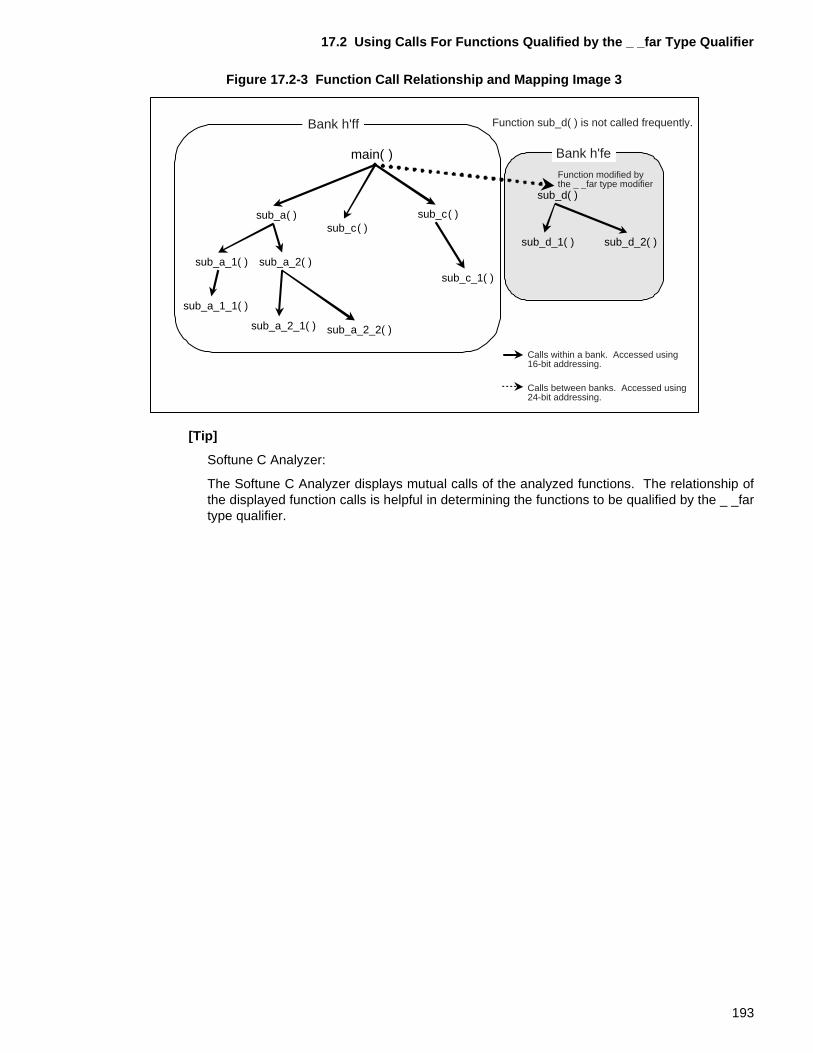
17.2 Using Calls For Functions Qualified by the _ _far Type Qualifier
Figure 17.2-3 Function Call Relationship and Mapping Image 3
[Tip]
Softune C Analyzer:
The Softune C Analyzer displays mutual calls of the analyzed functions. The relationship ofthe displayed function calls is helpful in determining the functions to be qualified by the _ _fartype qualifier.
main( )
sub_a( ) sub_c( )
sub_d( )
sub_a_1( )
sub_a_1_1( )
sub_a_2( )
sub_c_1( )
sub_a_2_1( ) sub_a_2_2( )
sub_d_1( ) sub_d_2( )
Bank h'ff
Bank h'fe
sub_c( )
Function modified by the _ _far type modifier
Function sub_d( ) is not called frequently.
Calls within a bank. Accessed using 16-bit addressing.
Calls between banks. Accessed using 24-bit addressing.
193
CHAPTER 17 MAPPING PROGRAMS IN WHICH THE CODE AREA EXCEEDS 64 Kbytes
17.3 Mapping Functions Qualified by the _ _far Type Qualifier
This section provides notes on mapping functions qualified by the _ _far type qualifier. The output section name of a function is dependent on the memory model specified at compilation. A function qualified by the _ _far type qualifier is always output to a section called "CODE_module name."
■ Memory Models and Output Sections of Functions Qualified by the _ _far Type Qualifier
The output section name of a function is dependent on the memory model specified atcompilation. The output section of a function qualified by the _ _far type qualifier, however, isnot dependent on the memory model. The function is always output to a section called"CODE_module name." Sections 17.3.1 "Functions Qualified by the _ _far Type Qualifier forSmall and Compact Models" and 17.3.2 "Functions Qualified by the _ _far Type Qualifier forMedium and Large Models" provide notes on mapping functions qualified by the _ _far typequalifier for each memory model.
194
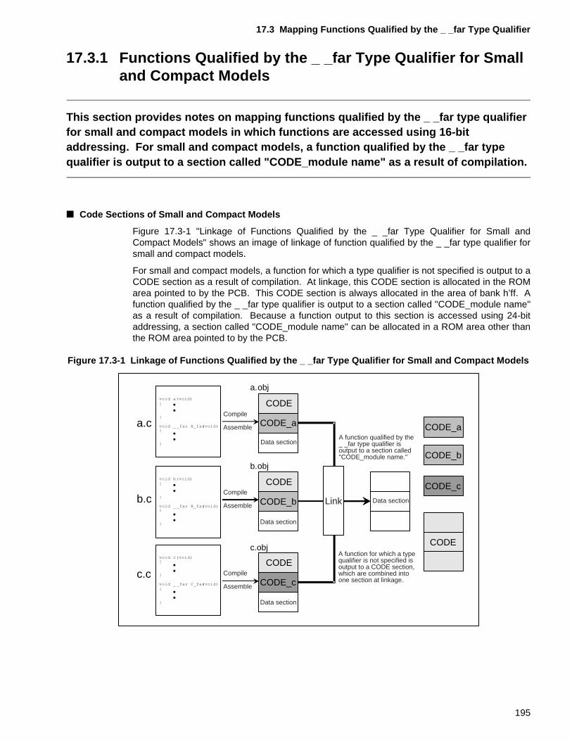
17.3 Mapping Functions Qualified by the _ _far Type Qualifier
17.3.1 Functions Qualified by the _ _far Type Qualifier for Small and Compact Models
This section provides notes on mapping functions qualified by the _ _far type qualifier for small and compact models in which functions are accessed using 16-bit addressing. For small and compact models, a function qualified by the _ _far type qualifier is output to a section called "CODE_module name" as a result of compilation.
■ Code Sections of Small and Compact Models
Figure 17.3-1 "Linkage of Functions Qualified by the _ _far Type Qualifier for Small andCompact Models" shows an image of linkage of function qualified by the _ _far type qualifier forsmall and compact models.
For small and compact models, a function for which a type qualifier is not specified is output to aCODE section as a result of compilation. At linkage, this CODE section is allocated in the ROMarea pointed to by the PCB. This CODE section is always allocated in the area of bank h’ff. Afunction qualified by the _ _far type qualifier is output to a section called "CODE_module name"as a result of compilation. Because a function output to this section is accessed using 24-bitaddressing, a section called "CODE_module name" can be allocated in a ROM area other thanthe ROM area pointed to by the PCB.
Figure 17.3-1 Linkage of Functions Qualified by the _ _far Type Qualifier for Small and Compact Models
CODE
CODE
CODE
CODE_a
CODE_b
CODE_c
Data section
CODE
CODE_a
CODE_b
CODE_c
Compile
Assemble
Compile
Assemble
Compile
Assemble
Link
a.c
b.c
c.c
a.obj
b.obj
c.obj
A function qualified by the _ _far type qualifier is output to a section called "CODE_module name."
A function for which a type qualifier is not specified is output to a CODE section, which are combined into one section at linkage.
Data section
Data section
Data section
195
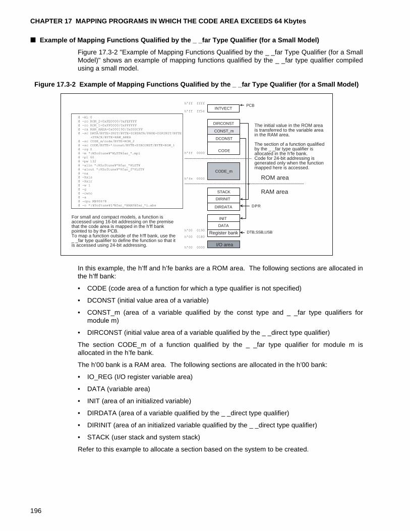
CHAPTER 17 MAPPING PROGRAMS IN WHICH THE CODE AREA EXCEEDS 64 Kbytes
■ Example of Mapping Functions Qualified by the _ _far Type Qualifier (for a Small Model)
Figure 17.3-2 "Example of Mapping Functions Qualified by the _ _far Type Qualifier (for a SmallModel)" shows an example of mapping functions qualified by the _ _far type qualifier compiledusing a small model.
Figure 17.3-2 Example of Mapping Functions Qualified by the _ _far Type Qualifier (for a Small Model)
In this example, the h’ff and h’fe banks are a ROM area. The following sections are allocated inthe h’ff bank:
• CODE (code area of a function for which a type qualifier is not specified)
• DCONST (initial value area of a variable)
• CONST_m (area of a variable qualified by the const type and _ _far type qualifiers formodule m)
• DIRCONST (initial value area of a variable qualified by the _ _direct type qualifier)
The section CODE_m of a function qualified by the _ _far type qualifier for module m isallocated in the h’fe bank.
The h’00 bank is a RAM area. The following sections are allocated in the h’00 bank:
• IO_REG (I/O register variable area)
• DATA (variable area)
• INIT (area of an initialized variable)
• DIRDATA (area of a variable qualified by the _ _direct type qualifier)
• DIRINIT (area of an initialized variable qualified by the _ _direct type qualifier)
• STACK (user stack and system stack)
Refer to this example to allocate a section based on the system to be created.
I/O area
DATA
INIT
DIRDATA
DIRINIT
STACK
CODE
DCONST
DIRCONST
CONST_m
INTVECT
DTB,SSB,USB
DPR
PCB
CODE_m
ROM area
RAM area
For small and compact models, a function is accessed using 16-bit addressing on the premise that the code area is mapped in the h'ff bank pointed to by the PCB. To map a function outside of the h'ff bank, use the _ _far type qualifier to define the function so that it is accessed using 24-bit addressing.
The initial value in the ROM area is transferred to the variable area in the RAM area.
The section of a function qualified by the _ _far type qualifier is allocated in the h'fe bank. Code for 24-bit addressing is generated only when the function mapped here is accessed.
Register bank
h�ff ffff
h�ff ff54
h�ff 0000
h�00 0000
h�00 0180
@ -AL 0@ -ro ROM_2=0xFE0000/0xFEFFFF@ -ro ROM_1=0xFF0000/0xFFFFFF@ -ra RAM_AREA=0x000190/0x000CFF@ -sc DATA/BYTE+INIT/BYTE+DIRDATA/PAGE+DIRINIT/BYTE
+STACK/BYTE=RAM_AREA@ -sc CODE_m/code/BYTE=ROM_2@ -sc CODE/BYTE+*/const/BYTE+DIRCONST/BYTE=ROM_1@ -rg 0@ -m *:¥Softune¥*¥LST¥far_*.mp1@ -pl 60@ -pw 132@ -alin *:¥Softune¥*¥far_*¥LST¥@ -alout *:¥Softune¥*¥far_f*¥LST¥@ -na@ -Xals@ -Xalr@ -w 1@ -g@ -cwno@ -a@ -cpu MB90678@ -o *:¥Softune¥1*¥far_*¥ABS¥far_*l.abs
h�00 0190
h�fe 0000
196
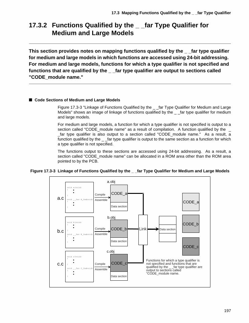
17.3 Mapping Functions Qualified by the _ _far Type Qualifier
17.3.2 Functions Qualified by the _ _far Type Qualifier for Medium and Large Models
This section provides notes on mapping functions qualified by the _ _far type qualifier for medium and large models in which functions are accessed using 24-bit addressing. For medium and large models, functions for which a type qualifier is not specified and functions that are qualified by the _ _far type qualifier are output to sections called "CODE_module name."
■ Code Sections of Medium and Large Models
Figure 17.3-3 "Linkage of Functions Qualified by the _ _far Type Qualifier for Medium and LargeModels" shows an image of linkage of functions qualified by the _ _far type qualifier for mediumand large models.
For medium and large models, a function for which a type qualifier is not specified is output to asection called "CODE_module name" as a result of compilation. A function qualified by the __far type qualifier is also output to a section called "CODE_module name." As a result, afunction qualified by the _ _far type qualifier is output to the same section as a function for whicha type qualifier is not specified.
The functions output to these sections are accessed using 24-bit addressing. As a result, asection called "CODE_module name" can be allocated in a ROM area other than the ROM areapointed to by the PCB.
Figure 17.3-3 Linkage of Functions Qualified by the _ _far Type Qualifier for Medium and Large Models
CODE_aa.c
b.c
c.c
a.obj
b.obj
c.obj
CODE_b
CODE_c
CODE_a
CODE_b
CODE_c
Data section
Compile
Assemble
Compile
Assemble
Compile
Assemble
Data section
Data section
Data section
Link
Functions for which a type qualifier is not specified and functions that are qualified by the _ _far type qualifier are output to sections called "CODE_module name.
197
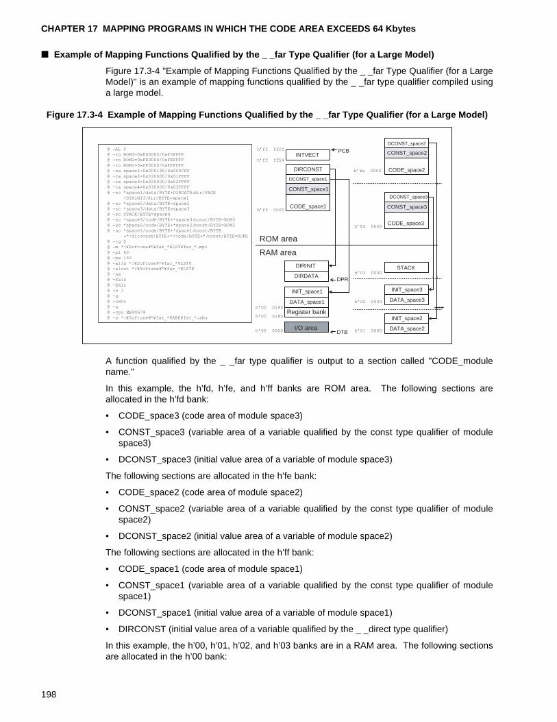
CHAPTER 17 MAPPING PROGRAMS IN WHICH THE CODE AREA EXCEEDS 64 Kbytes
■ Example of Mapping Functions Qualified by the _ _far Type Qualifier (for a Large Model)
Figure 17.3-4 "Example of Mapping Functions Qualified by the _ _far Type Qualifier (for a LargeModel)" is an example of mapping functions qualified by the _ _far type qualifier compiled usinga large model.
Figure 17.3-4 Example of Mapping Functions Qualified by the _ _far Type Qualifier (for a Large Model)
A function qualified by the _ _far type qualifier is output to a section called "CODE_modulename."
In this example, the h’fd, h’fe, and h’ff banks are ROM area. The following sections areallocated in the h’fd bank:
• CODE_space3 (code area of module space3)
• CONST_space3 (variable area of a variable qualified by the const type qualifier of modulespace3)
• DCONST_space3 (initial value area of a variable of module space3)
The following sections are allocated in the h’fe bank:
• CODE_space2 (code area of module space2)
• CONST_space2 (variable area of a variable qualified by the const type qualifier of modulespace2)
• DCONST_space2 (initial value area of a variable of module space2)
The following sections are allocated in the h’ff bank:
• CODE_space1 (code area of module space1)
• CONST_space1 (variable area of a variable qualified by the const type qualifier of modulespace1)
• DCONST_space1 (initial value area of a variable of module space1)
• DIRCONST (initial value area of a variable qualified by the _ _direct type qualifier)
In this example, the h’00, h’01, h’02, and h’03 banks are in a RAM area. The following sectionsare allocated in the h’00 bank:
I/O area
Register bank
DATA_space1
INIT_space1
DIRDATA
DIRINIT STACK
CODE_space1
DCONST_space1
DIRCONST
CONST_space1
INTVECT
DTB
DPR
PCB
CODE_space3
DCONST_space3
CONST_space3
CODE_space2
DCONST_space2
CONST_space2
DATA_space2
INIT_space2
DATA_space3
INIT_space3
RAM area
ROM area
h�ff ffff
h�ff ff54
h�ff 0000
h�00 0000
h�00 0180
h�00 0190
h�fd 0000
@ -AL 0@ -ro ROM3=0xFD0000/0xFDFFFF@ -ro ROM2=0xFE0000/0xFEFFFF@ -ro ROM1=0xFF0000/0xFFFFFF@ -ra space1=0x000190/0x000CFF@ -ra space2=0x010000/0x01FFFF@ -ra space3=0x020000/0x02FFFF@ -ra space4=0x030000/0x03FFFF@ -sc *space1/data/BYTE+DIRDATA/dir/PAGE
+DIRINIT/dir/BYTE=space1@ -sc *space2/data/BYTE=space2@ -sc *space3/data/BYTE=space3@ -sc STACK/BYTE=space4@ -sc *space3/code/BYTE+*space3/const/BYTE=ROM3@ -sc *space2/code/BYTE+*space2/const/BYTE=ROM2@ -sc *space1/code/BYTE+*space1/const/BYTE
+*/dirconst/BYTE+*/code/BYTE+*/const/BYTE=ROM1@ -rg 0@ -m *:¥Softune¥*¥far_*¥LST¥far_*.mp1@ -pl 60@ -pw 132@ -alin *:¥Softune¥*¥far_*¥LST¥@ -alout *:¥Softune¥*¥far_*¥LST¥@ -na@ -Xals@ -Xalr@ -w 1@ -g@ -cwno@ -a@ -cpu MB90678@ -o *:¥Softune¥*¥far_*¥ABS¥far_*.abs
h�fe 0000
h�03 0000
h�02 0000
h�01 0000
198
17.3 Mapping Functions Qualified by the _ _far Type Qualifier
• IO_REG (I/O register variable area)
• DATA_space1 (variable area of module space1)
• INIT_space1 (area of an initialized variable of module space1)
• DIRDATA (variable area of a variable qualified by the _ _direct type qualifier)
• DIRINIT (variable area of an initialized variable qualified by the _ _direct type qualifier)
The following sections are allocated in the h’01 bank:
• DATA_space2 (variable area of module space2)
• INIT_space2 (area of an initialized variable of module space2)
The following sections are allocated in the h’02 bank:
• DATA_space3 (variable area of module space3)
• INIT_space3 (area of an initialized variable of module space3)
The following section is allocated in the h’03 bank:
• STACK (user stack and system stack)
Refer to this example to allocate each section based on the system to be created.
199
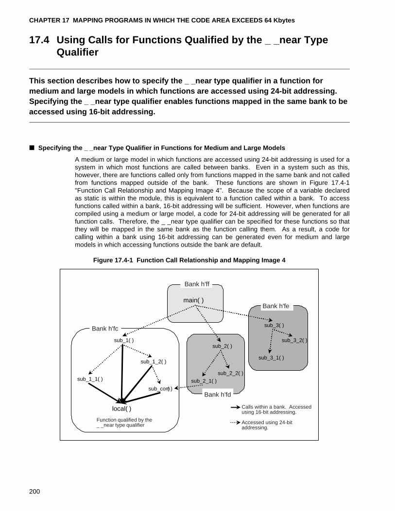
CHAPTER 17 MAPPING PROGRAMS IN WHICH THE CODE AREA EXCEEDS 64 Kbytes
17.4 Using Calls for Functions Qualified by the _ _near Type Qualifier
This section describes how to specify the _ _near type qualifier in a function for medium and large models in which functions are accessed using 24-bit addressing.Specifying the _ _near type qualifier enables functions mapped in the same bank to be accessed using 16-bit addressing.
■ Specifying the _ _near Type Qualifier in Functions for Medium and Large Models
A medium or large model in which functions are accessed using 24-bit addressing is used for asystem in which most functions are called between banks. Even in a system such as this,however, there are functions called only from functions mapped in the same bank and not calledfrom functions mapped outside of the bank. These functions are shown in Figure 17.4-1"Function Call Relationship and Mapping Image 4". Because the scope of a variable declaredas static is within the module, this is equivalent to a function called within a bank. To accessfunctions called within a bank, 16-bit addressing will be sufficient. However, when functions arecompiled using a medium or large model, a code for 24-bit addressing will be generated for allfunction calls. Therefore, the _ _near type qualifier can be specified for these functions so thatthey will be mapped in the same bank as the function calling them. As a result, a code forcalling within a bank using 16-bit addressing can be generated even for medium and largemodels in which accessing functions outside the bank are default.
Figure 17.4-1 Function Call Relationship and Mapping Image 4
main( )
sub_1( )sub_2( )
sub_3( )
sub_1_1( )
sub_1_2( )
sub_2_1( )
sub_2_2( )
sub_3_1( )
sub_3_2( )
Bank h'fe
Function qualified by the _ _near type qualifier
local( )
sub_com( )
Bank h'ff
Bank h'fc
Bank h'fd
Calls within a bank. Accessed using 16-bit addressing.
Accessed using 24-bit addressing.
200
17.4 Using Calls for Functions Qualified by the _ _near Type Qualifier
[Tip]
Softune C Analyzer:
The Softune C Analyzer displays mutual calls of the analyzed functions. The relationship ofthe displayed function calls is helpful in determining the functions to be qualified by the __near type qualifier.
201
CHAPTER 17 MAPPING PROGRAMS IN WHICH THE CODE AREA EXCEEDS 64 Kbytes
17.5 Mapping Functions Qualified by the _ _near Type Qualifier
This section provides notes on mapping functions qualified by the _ _near type qualifier for medium and large models in which functions are accessed using 24-bit addressing.For medium and large models, a function qualified by the _ _near type qualifier is output to a section called "CODE_module name" in the same way as other functions.
■ Memory Models and Output Sections of Functions Qualified by the _ _near Type Qualifier
The output section name of a function is dependent on the memory model specified atcompilation. For small and medium models, a function qualified by the _ _near type qualifier isoutput to a CODE section in the same way as a function for which a type qualifier is notspecified.
For medium and large models, a function for which a type qualifier is not specified is output to asection called "CODE_module name." A function qualified by the _ _near type qualifier is alsooutput to a section called "CODE_module name."
Figure 17.5-1 "Linkage of Functions Qualified by the _ _near Type Qualifier for Medium andLarge Models" shows an image of linkage of functions qualified by the _ _near type qualifier formedium and large models.
The function A_near( ) defined in module a is output to the CODE_a section. The functionB_near( ) defined in module b is output to the CODE_b section. In the same way, the functionC_near( ) defined in module c is output to the CODE_c section. At linkage, these sections areallocated in the same bank as the module in which the function is defined.
Figure 17.5-1 Linkage of Functions Qualified by the _ _near Type Qualifier for Medium and Large Models
CODE_aa.c
b.c
c.c
a.obj
b.obj
c.obj
CODE_b
CODE_c
CODE_a
CODE_b
CODE_c
Data section
Compile
Assemble
Compile
Assemble
Compile
Assemble
Link Data section
Data section
Data section
Functions qualified by the _ _near type qualifier and functions for which a type qualifier is not specified are output to sections called "CODE_module name."
202

17.5 Mapping Functions Qualified by the _ _near Type Qualifier
■ Example of Mapping Functions Qualified by the _ _near Type Qualifier (for a Medium Model)
For medium and large models, functions are accessed using 24-bit addressing using the PCBregister. For medium and large models, when a function qualified by the _ _near type qualifieris called from a function for which a type qualifier is not specified, the calling function and calledfunction must be mapped in the same bank. The PCB that is set when calling a function forwhich a type qualifier is not specified is used as is for calling a function qualified by the _ _neartype qualifier.
Figure 17.5-2 "Example of Mapping Functions Qualified by the _ _near Type Qualifier (for aMedium Model)" is an example of mapping functions qualified by the _ _near type qualifiercompiled using a medium model. The functions qualified by the _ _near type qualifier areoutput to sections called "CODE_module name" in the same way as functions for which a typequalifier is not specified.
Figure 17.5-2 Example of Mapping Functions Qualified by the _ _near Type Qualifier (for a Medium Model)
In this example, the h’fd, h’fe, and h’ff banks are ROM area. The following section is allocatedin the h’fd bank:
• CODE_space3 (code area of module space3)
The following section is allocated in the h’fe bank:
• CODE_space2 (code area of module space2)
The following sections are allocated in the h’ff bank:
• CODE_space1 (code area of module space1)
• DIRCONST (initial value area of a variable qualified by the _ _direct type qualifier)
• DCONST (initial value area of a variable)
• CONST (variable area of a variable qualified by the const type qualifier)
In this example, the h’00 bank is RAM area. The following sections are allocated in the h’00bank:
I/O area
Register bank
DATA
INIT
DIRDATA
DIRINIT
STACK
CODE_space1
DCONST
DIRCONST
CONST
INTVECT
DTB
DPR
PCB
CODE_space3
CODE_space2
RAM area
ROM area
h�ff ffff
h�ff ff54
h�ff 0000
h�00 0000
h�00 0180
h�00 0190
h�fd 0000
h�fe 0000
@ -AL 0@ -ro ROM3=0xFD0000/0xFDFFFF@ -ro ROM2=0xFE0000/0xFEFFFF@ -ro ROM1=0xFF0000/0xFFFFFF@ -ra space1=0x000190/0x000CFF@ -sc */data/BYTE+DIRDATA/dir/PAGE+DIRINIT/dir/BYTE
+STACK/stack/WORD=space1@ -sc CODE_space3/code/BYTE=ROM3@ -sc CODE_space2/code/BYTE=ROM2@ -sc *space1/code/BYTE+*space1/const/BYTE
+*/dirconst/BYTE+*/code/BYTE+*/const/BYTE=ROM1@ -rg 0@ -m *:¥Softune¥*¥near_*¥LST¥near_*.mp1@ -pl 60@ -pw 132@ -alin *:¥Softune¥*¥near_*¥LST¥@ -alout *:¥Softune¥*¥near_*¥LST¥@ -na@ -Xals@ -Xalr@ -w 1@ -g@ -cwno@ -a@ -cpu MB90678@ -o *:¥Softune¥*¥near_*¥ABS¥near_*.abs
h�ff 4000
203
CHAPTER 17 MAPPING PROGRAMS IN WHICH THE CODE AREA EXCEEDS 64 Kbytes
• IO_REG (I/O register variable area)
• DATA (variable area)
• INIT (area of an initialized variable)
• DIRDATA (variable area of a variable qualified by the _ _direct type qualifier)
• DIRINIT (variable area of an initialized variable qualified by the _ _direct type qualifier)
• STACK (user stack and system stack)
Refer to this example to allocate each section based on the system to be created.
204
CHAPTER 18 MAPPING PROGRAMS IN WHICH THE DATA AREA EXCEEDS 64 Kbytes
This chapter describes how to map programs in which the data area of the program to be created exceeds 64 Kbytes.For a system in which the data area exceeds 64 Kbytes even slightly, it is recommended that a small or compact model be used and that the _ _far type qualifier be specified in the functions.
18.1 "Function Calls of Programs Where the Data Area Exceeds 64 Kbytes"
18.2 "Using Calls for Variables Qualified by the _ _far Type Qualifier"
18.3 "Mapping Variables Qualified by the _ _far Type Qualifier"
18.4 "Using Calls For Variables Qualified by the _ _near Type Qualifier"
18.5 "Mapping Variables Qualified by the _ _near Type Qualifier"
205
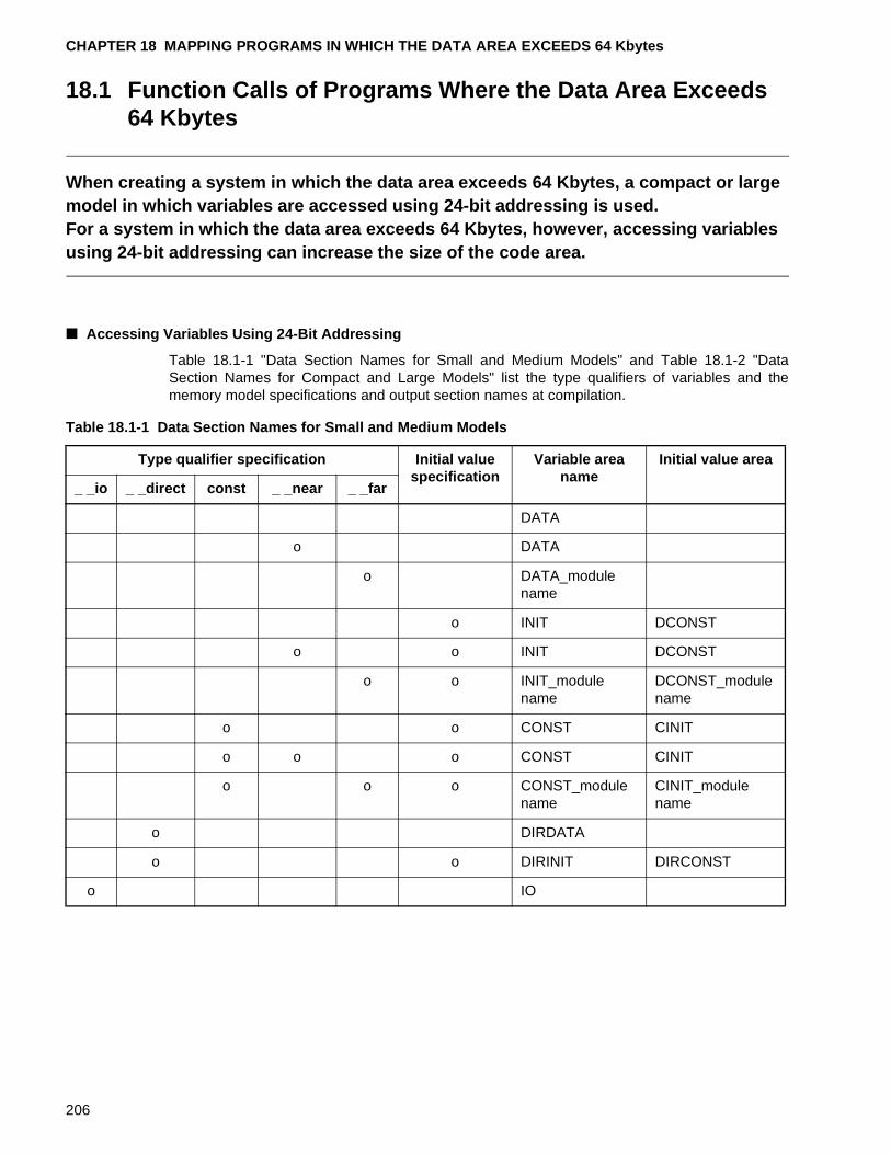
CHAPTER 18 MAPPING PROGRAMS IN WHICH THE DATA AREA EXCEEDS 64 Kbytes
18.1 Function Calls of Programs Where the Data Area Exceeds 64 Kbytes
When creating a system in which the data area exceeds 64 Kbytes, a compact or large model in which variables are accessed using 24-bit addressing is used.For a system in which the data area exceeds 64 Kbytes, however, accessing variables using 24-bit addressing can increase the size of the code area.
■ Accessing Variables Using 24-Bit Addressing
Table 18.1-1 "Data Section Names for Small and Medium Models" and Table 18.1-2 "DataSection Names for Compact and Large Models" list the type qualifiers of variables and thememory model specifications and output section names at compilation.
Table 18.1-1 Data Section Names for Small and Medium Models
Type qualifier specification Initial value specification
Variable area name
Initial value area
_ _io _ _direct const _ _near _ _far
DATA
o DATA
o DATA_module name
o INIT DCONST
o o INIT DCONST
o o INIT_module name
DCONST_module name
o o CONST CINIT
o o o CONST CINIT
o o o CONST_module name
CINIT_module name
o DIRDATA
o o DIRINIT DIRCONST
o IO
206
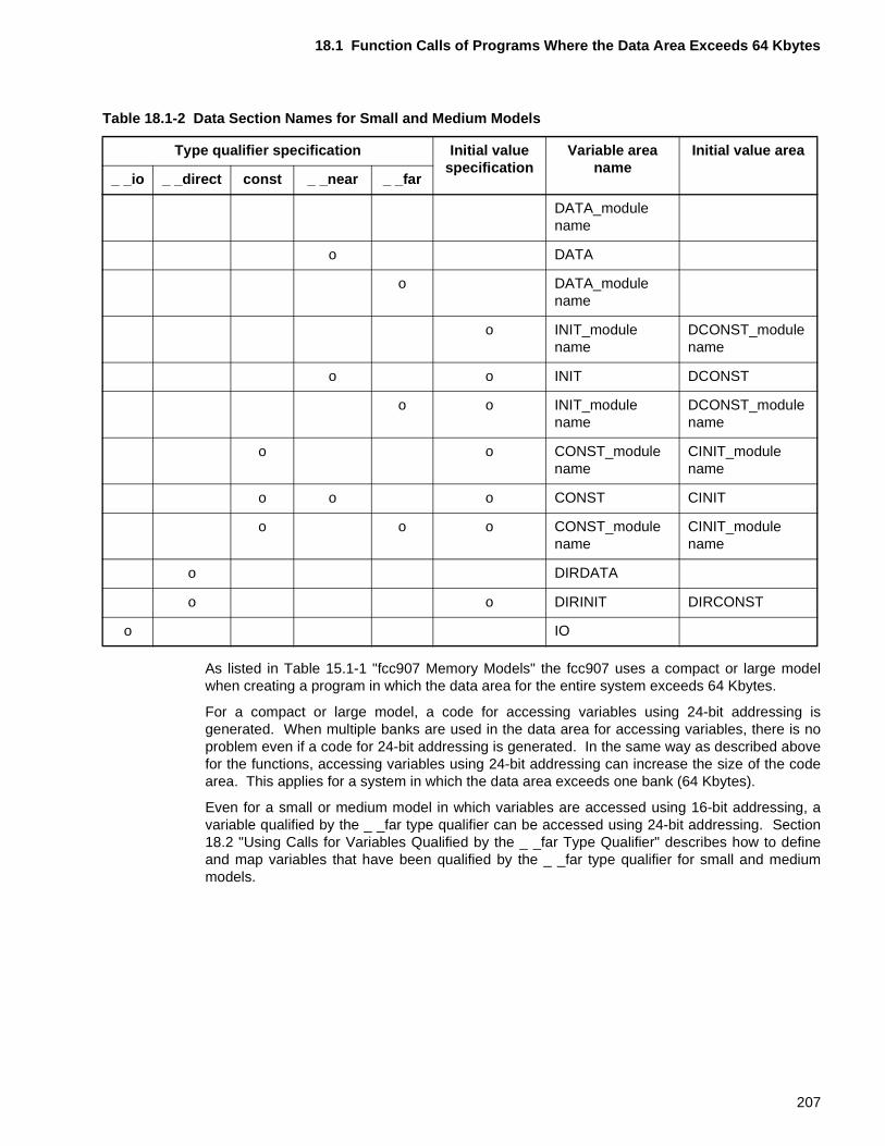
18.1 Function Calls of Programs Where the Data Area Exceeds 64 Kbytes
As listed in Table 15.1-1 "fcc907 Memory Models" the fcc907 uses a compact or large modelwhen creating a program in which the data area for the entire system exceeds 64 Kbytes.
For a compact or large model, a code for accessing variables using 24-bit addressing isgenerated. When multiple banks are used in the data area for accessing variables, there is noproblem even if a code for 24-bit addressing is generated. In the same way as described abovefor the functions, accessing variables using 24-bit addressing can increase the size of the codearea. This applies for a system in which the data area exceeds one bank (64 Kbytes).
Even for a small or medium model in which variables are accessed using 16-bit addressing, avariable qualified by the _ _far type qualifier can be accessed using 24-bit addressing. Section18.2 "Using Calls for Variables Qualified by the _ _far Type Qualifier" describes how to defineand map variables that have been qualified by the _ _far type qualifier for small and mediummodels.
Table 18.1-2 Data Section Names for Small and Medium Models
Type qualifier specification Initial value specification
Variable area name
Initial value area
_ _io _ _direct const _ _near _ _far
DATA_module name
o DATA
o DATA_module name
o INIT_module name
DCONST_module name
o o INIT DCONST
o o INIT_module name
DCONST_module name
o o CONST_module name
CINIT_module name
o o o CONST CINIT
o o o CONST_module name
CINIT_module name
o DIRDATA
o o DIRINIT DIRCONST
o IO
207
CHAPTER 18 MAPPING PROGRAMS IN WHICH THE DATA AREA EXCEEDS 64 Kbytes
18.2 Using Calls For Variables Qualified by the _ _far Type Qualifier
This section describes how to specify the _ _far type qualifier in a variable for small and medium models where variables are accessed using 16-bit addressing.It is recommended that the _ _far type qualifier be specified for variables not accessed frequently or variables called from all functions.
■ Specifying the _ _far Type Qualifier in a Variable for Small and Medium Models
When creating a system in which the data area exceeds 64 Kbytes, a code for 24-bit addressingwill be generated even when variables mapped in the bank pointed to by the DTB are accessed.This applies when a compact or large model is used in which all variables are accessed using24-bit addressing. Even for a small model in which variables mapped in the bank pointed to bythe DTB are accessed using 16-bit addressing, the _ _far type qualifier can be specified so thatthe variables outside of the bank pointed to by the DTB can be accessed using 24-bitaddressing.
When creating a system in which the data area exceeds 64 Kbytes, it is recommended that the_ _far type qualifier be specified for some of the variables at compilation for a small or mediummodel.
■ Specifying the _ _far Type Qualifier in Variables Depending on Access Frequency
The access frequency of the variables in the entire system to be developed is not defined.Some variables are accessed frequently while others are accessed infrequently. When creatinga system in which the data area exceeds 64 Kbytes, the variables frequently accessed aremapped in the bank pointed to by the DTB as shown in Figure 18.2-1 "Variable AccessRelationship and Mapping Image 1". The _ _far type qualifier can be specified for a variablethat exceeds 64 Kbytes so that the variable is mapped outside the bank pointed to by the DTB.As a result, code for 24-bit addressing is generated only when a variable qualified by the _ _fartype qualifier is accessed.
208
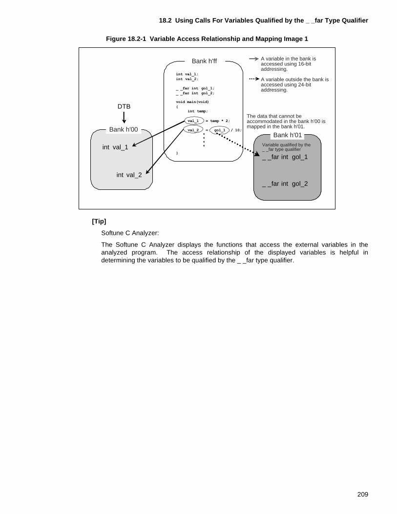
18.2 Using Calls For Variables Qualified by the _ _far Type Qualifier
Figure 18.2-1 Variable Access Relationship and Mapping Image 1
[Tip]
Softune C Analyzer:
The Softune C Analyzer displays the functions that access the external variables in theanalyzed program. The access relationship of the displayed variables is helpful indetermining the variables to be qualified by the _ _far type qualifier.
Variable qualified by the _ _far type qualifierint val_1
int val_2
_ _far int gol_1
_ _far int gol_2
DTB
Bank h'ff
Bank h'00Bank h'01
A variable in the bank is accessed using 16-bit addressing.
A variable outside the bank is accessed using 24-bit addressing.
The data that cannot be accommodated in the bank h'00 is mapped in the bank h'01.
209
CHAPTER 18 MAPPING PROGRAMS IN WHICH THE DATA AREA EXCEEDS 64 Kbytes
18.3 Mapping Variables Qualified by the _ _far Type Qualifier
This section provides notes on mapping variables qualified by the _ _far type qualifier.The output section name of a variable depends on the memory model specified at compilation. A variable qualified by the _ _far type qualifier, however, is output to a section called "XXXX_module name" regardless of the specified memory model.
■ Memory Models and Output Sections of Variables Qualified by the _ _far Type Qualifier
The output section name of a variable is dependent on the memory model specified atcompilation. A variable qualified by the _ _far type qualifier, however, is always output to asection called "XXXX_module name" regardless of the specified memory model. Sections18.3.1 "Variables Qualified by the _ _far Type Qualifier for Small and Medium Models" and18.3.2 "Variables Qualified by the _ _far Type Qualifier for Compact and Large Models" providenotes on mapping variables qualified by the _ _far type qualifier for each memory model.
210
18.3 Mapping Variables Qualified by the _ _far Type Qualifier
18.3.1 Variables Qualified by the _ _far Type Qualifier for Small and Medium Models
This section provides notes on mapping variables qualified by the _ _far type qualifier for small and medium models in which variables are accessed using 16-bit addressing.For small and medium models, a variable qualified by the _ _far type qualifier is output to a section called "XXXX_module name."
■ Code Sections of Small and Medium Models
Figure 18.3-1 "Linkage of Variables Qualified by the _ _far Type Qualifier for Small and MediumModels" shows an image of linkage of variables qualified by the _ _far type qualifier for smalland medium models.
For small and medium models, the output section name as a result of compilation is different fora variable for which a _ _far type qualifier is not specified than it is for a variable for which the __far type qualifier is specified.
For a variable for which a type qualifier is not specified, the variable is output to a DATA, INIT,DCONST, or CONST section depending on the nature of the variable. Among these sections,the variable areas (DATA and INIT) are allocated in the bank pointed to by the DTB. Normally,these variable areas are allocated in the bank h’00. As a result, a variable output in the DATAor INIT section is accessed using 16-bit addressing.
A variable qualified by the _ _far type qualifier is output to a section in which "_module name"has been added to the section name. That is, a variable qualified by the _ _far type qualifier isoutput to a section called "DATA_module name," INIT_module name," "DCONST_modulename," or "CONST_module name." These variables are accessed using 24-bit addressing. Asa result, a section called "XXXX_module name" can be allocated in an area outside of the bankpointed to by the DTB.
211
CHAPTER 18 MAPPING PROGRAMS IN WHICH THE DATA AREA EXCEEDS 64 Kbytes
Figure 18.3-1 Linkage of Variables Qualified by the _ _far Type Qualifier for Small and Medium Models
■ Example of Mapping Variables Qualified by the _ _far Type Qualifier (for a Small Model)
Figure 18.3-2 "Example of Mapping Variables Qualified by the _ _far Type Qualifier (for a SmallModel)" is an example of mapping variables qualified by the _ _far type qualifier compiled usinga small model.
Figure 18.3-2 Example of Mapping Variables Qualified by the _ _far Type Qualifier (for a Small Model)
A variable qualified by the _ _far type qualifier is output to a section called "XXXX_modulename."
XXXX_a
XXXX_b
XXXX_c
XXXX_a
XXXX_b
XXXX_c
a.c
b.c
c.c
a.obj
b.obj
c.obj
Data sectionCompile
Assemble
Compile
Assemble
Compile
Assemble
Link Data sectionData section
Data section
Data section of a variable qualified by the _ _far type qualifier
Data section of a variable qualified by the _ _far type qualifier
Data section of a variable qualified by the _ _far type qualifier
A variable qualified by the _ _far type qualifier is output to a section called "XXXX_module name."
Code section
Code section
Code section
Code section
_ _far int c1 = 100;_ _far int c2 = 200;
_ _far int C_data1;_ _far int C_data2;
int c1_data;int c2_data;
_ _far int b1 = 100;_ _far int b2 = 200;
_ _far int B_data1;_ _far int B_data2;
int b1_data;int b2_data;
_ _far int a1 = 100;_ _far int a2 = 200;
_ _far int A_data1;_ _far int A_data2;
int a1_data;int a2_data;
I/O area
Register bank
DATA
INIT
DIRDATA
DIRINIT
STACK
CODE
DCONST
DIRCONST
CONST_m
INTVECT
DTB
DPR
PCB
DATA_m
INIT_m
DCONST_m
ROM area RAM area
h�ff ffff
h�ff ff54
h�ff 0000
h�00 0000
h�00 0180
h�00 0190
@ -AL 0@ -ro ROM_AREA=0xFF0000/0xFFFFFF@ -ra RAM_AREA=0x000190/0x000CFF@ -ra FAR_RAM=0x010000/0x01FFFF@ -sc DATA/data/BYTE+INIT/data/BYTE+DIRDATA/dir/PAGE
+DIRINIT/BYTE+STACK/stack/BYTE=RAM_AREA@ -sc *mm/data/BYTE=FAR_RAM@ -sc CODE/code/BYTE+*/const/BYTE
+*/dirconst/BYTE=ROM_AREA@ -rg 0@ -m D:¥Softune¥*¥far_*¥LST¥far_*.mp1@ -pl 60@ -pw 132@ -alin D:¥Softune¥*¥far_*¥LST¥@ -alout D:¥Softune¥*¥far_*¥LST¥@ -na@ -Xals@ -Xalr@ -w 1@ -g@ -cwno@ -a@ -cpu MB90P678@ -o D:¥Softune¥*¥far_*¥ABS¥far_*l.abs
h�01 0000
212
18.3 Mapping Variables Qualified by the _ _far Type Qualifier
In this example, the h’ff bank is a ROM area. The following sections are allocated in the h’ffbank:
• CODE (code area)
• DCONST (initial value area of a variable)
• DCONST_m (initial value area of a variable qualified by the _ _far type qualifier for modulem)
• CONST_m (variable area of a variable qualified by the _ _far type and const type qualifiersfor module m)
• DIRCONST (initial value area of a variable qualified by the _ _direct type qualifier)
The h’00 bank and h’01 banks are a RAM area. The following sections are allocated in the h’00bank:
• IO_REG (I/O register variable area)
• DATA (variable area)
• INIT (area of an initialized variable)
• DIRDATA (area of a variable qualified by the _ _direct type qualifier)
• DIRINIT (area of an initialized variable qualified by the _ _direct type qualifier)
• STACK (user stack and system stack)
The sections of the following variables qualified by the _ _far type qualifier for module m areallocated in the h’01 bank:
• DATA_m (variable area)
• INIT_m (area of an initialized variable)
Refer to this example to allocate each section based on the system to be created
213
CHAPTER 18 MAPPING PROGRAMS IN WHICH THE DATA AREA EXCEEDS 64 Kbytes
18.3.2 Variables Qualified by the _ _far Type Qualifier for Compact and Large Models
This section provides notes on mapping variables qualified by the _ _far type qualifier for compact and large models in which variables are accessed using 24-bit addressing.For compact and large models, variables for which the _ _far type or _ _near type qualifier has not been specified and variables qualified by the _ _far type qualifier are output to sections called "XXXX_module name."
■ Data Sections of Compact and Large Models
Figure 18.3-3 "Linkage of Variables Qualified by the _ _far Type Qualifier for Compact andLarge Models" is an image of linkage of variables qualified by the _ _far type qualifier forcompact and large models.
For compact and large models, a variable for which the _ _far type or _ _near type qualifier hasnot been specified is output to a section called "XXXX_module name" as a result of compilation.A variable qualified by the _ _far type qualifier is also output to a section called "XXXX_modulename" in the same way.
Therefore, a variable qualified by the _ _far type qualifier is output to the same section of thesame module as a variable for which the _ _far type qualifier has not been specified.
The variables output to these sections are accessed using 24-bit addressing. As a result, asection called "XXXX_module name" can be allocated in RAM area other than the RAM areapointed to by the DTB.
214
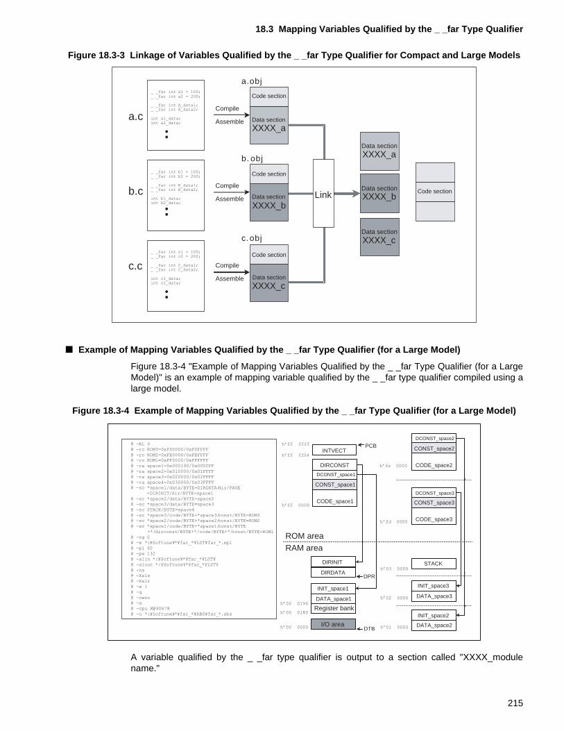
18.3 Mapping Variables Qualified by the _ _far Type Qualifier
Figure 18.3-3 Linkage of Variables Qualified by the _ _far Type Qualifier for Compact and Large Models
■ Example of Mapping Variables Qualified by the _ _far Type Qualifier (for a Large Model)
Figure 18.3-4 "Example of Mapping Variables Qualified by the _ _far Type Qualifier (for a LargeModel)" is an example of mapping variable qualified by the _ _far type qualifier compiled using alarge model.
Figure 18.3-4 Example of Mapping Variables Qualified by the _ _far Type Qualifier (for a Large Model)
A variable qualified by the _ _far type qualifier is output to a section called "XXXX_modulename."
XXXX_a
XXXX_b
XXXX_c
XXXX_b
a.c
b.c
c.c
a.obj
b. obj
c.obj
XXXX_a
XXXX_c
Data section
Compile
Assemble
Compile
Assemble
Compile
Assemble
Link Data section
Data section
Data section
Data section
Data section
Code section
Code section
Code section
Code section
_ _far int c1 = 100;_ _far int c2 = 200;
_ _far int C_data1;_ _far int C_data2;
int c1_data;int c2_data;
_ _far int b1 = 100;_ _far int b2 = 200;
_ _far int B_data1;_ _far int B_data2;
int b1_data;int b2_data;
_ _far int a1 = 100;_ _far int a2 = 200;
_ _far int A_data1;_ _far int A_data2;
int a1_data;int a2_data;
DATA_space1
INIT_space1
DIRDATA
DIRINIT STACK
CODE_space1
DCONST_space1
DIRCONST
CONST_space1
INTVECT
DTB
DPR
PCB
CODE_space3
DCONST_space3
CONST_space3
CODE_space2
DCONST_space2
CONST_space2
DATA_space2
INIT_space2
DATA_space3
INIT_space3
Register bank
ROM area RAM area
I/O area
h�ff ffff
h�ff ff54
h�ff 0000
h�00 0000
h�00 0180
h�00 0190
h�fd 0000
@ -AL 0@ -ro ROM3=0xFD0000/0xFDFFFF@ -ro ROM2=0xFE0000/0xFEFFFF@ -ro ROM1=0xFF0000/0xFFFFFF@ -ra space1=0x000190/0x000CFF@ -ra space2=0x010000/0x01FFFF@ -ra space3=0x020000/0x02FFFF@ -ra space4=0x030000/0x03FFFF@ -sc *space1/data/BYTE+DIRDATA/dir/PAGE
+DIRINIT/dir/BYTE=space1@ -sc *space2/data/BYTE=space2@ -sc *space3/data/BYTE=space3@ -sc STACK/BYTE=space4@ -sc *space3/code/BYTE+*space3/const/BYTE=ROM3@ -sc *space2/code/BYTE+*space2/const/BYTE=ROM2@ -sc *space1/code/BYTE+*space1/const/BYTE
+*/dirconst/BYTE+*/code/BYTE+*/const/BYTE=ROM1@ -rg 0@ -m *:¥Softune¥*¥far_*¥LST¥far_*.mp1@ -pl 60@ -pw 132@ -alin *:¥Softune¥*¥far_*¥LST¥@ -alout *:¥Softune¥*¥far_*¥LST¥@ -na@ -Xals@ -Xalr@ -w 1@ -g@ -cwno@ -a@ -cpu MB90678@ -o *:¥Softune¥*¥far_*¥ABS¥far_*.abs
h�fe 0000
h�03 0000
h�02 0000
h�01 0000
215
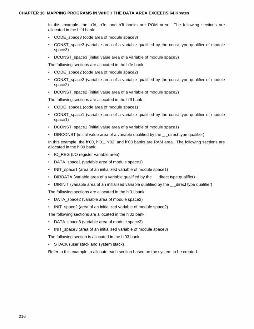
CHAPTER 18 MAPPING PROGRAMS IN WHICH THE DATA AREA EXCEEDS 64 Kbytes
In this example, the h’fd, h’fe, and h’ff banks are ROM area. The following sections areallocated in the h’fd bank:
• CODE_space3 (code area of module space3)
• CONST_space3 (variable area of a variable qualified by the const type qualifier of modulespace3)
• DCONST_space3 (initial value area of a variable of module space3)
The following sections are allocated in the h’fe bank
• CODE_space2 (code area of module space2)
• CONST_space2 (variable area of a variable qualified by the const type qualifier of modulespace2)
• DCONST_space2 (initial value area of a variable of module space2)
The following sections are allocated in the h’ff bank:
• CODE_space1 (code area of module space1)
• CONST_space1 (variable area of a variable qualified by the const type qualifier of modulespace1)
• DCONST_space1 (initial value area of a variable of module space1)
• DIRCONST (initial value area of a variable qualified by the _ _direct type qualifier)
In this example, the h’00, h’01, h’02, and h’03 banks are RAM area. The following sections areallocated in the h’00 bank:
• IO_REG (I/O register variable area)
• DATA_space1 (variable area of module space1)
• INIT_space1 (area of an initialized variable of module space1)
• DIRDATA (variable area of a variable qualified by the _ _direct type qualifier)
• DIRINIT (variable area of an initialized variable qualified by the _ _direct type qualifier)
The following sections are allocated in the h’01 bank:
• DATA_space2 (variable area of module space2)
• INIT_space2 (area of an initialized variable of module space2)
The following sections are allocated in the h’02 bank:
• DATA_space3 (variable area of module space3)
• INIT_space3 (area of an initialized variable of module space3)
The following section is allocated in the h’03 bank:
• STACK (user stack and system stack)
Refer to this example to allocate each section based on the system to be created.
216
18.4 Using Calls For Variables Qualified by the _ _near Type Qualifier
18.4 Using Calls For Variables Qualified by the _ _near Type Qualifier
This section describes how to specify the _ _near type qualifier in a variable for compact and large models where variables are accessed using 24-bit addressing.Specifying the _ _near type qualifier enables a variable mapped in the bank pointed to by the DTB to be accessed using 16-bit addressing.
■ Specifying the _ _near Type Qualifier in Variables for Compact and Large Models
A compact or large model in which all variables are accessed using 24-bit addressing is usedfor systems in which large numbers of variables are accessed. That is, the data area exceeds64 Kbytes. When a compact or large model is used, the variables are accessed using 24-bitaddressing.
This does not mean, however, that all of the variables are accessed with the same frequency.Some variables are accessed very frequently while others are accessed infrequently. When 24-bit addressing is used to access a variable that is accessed with high frequency, the code sizeis increased and execution speed at access is reduced.
As shown in Figure 18.4-1 "Variable Access Relationship and Mapping Image 2" specifying the_ _near type qualifier when compiling a variable that is frequently accessed will generate codefor accessing the variable using 16-bit addressing. The variable area of the variables qualifiedby the _ _near type qualifier will then be set in the bank pointed to by the DTB.
As a result, a variable mapped in the bank pointed to by the DTB can be accessed using 16-bitaddressing. This also applies for compact and large models in which variables are accessedusing 24-bit addressing by default.
217
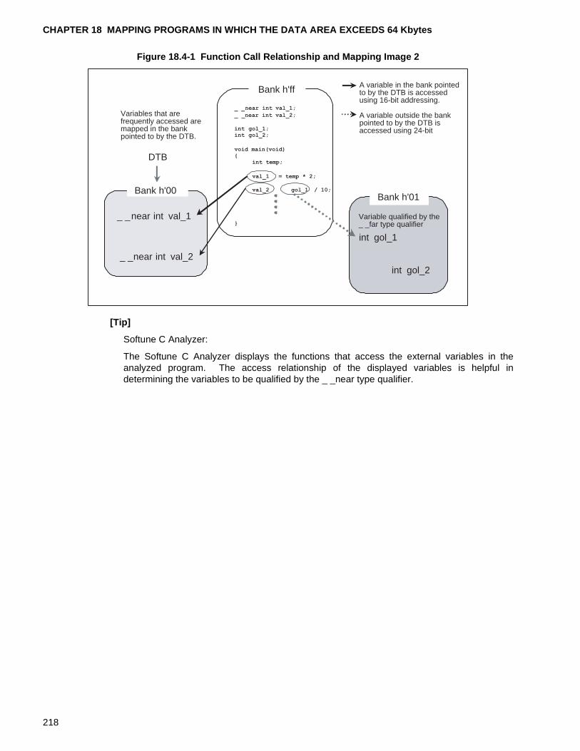
CHAPTER 18 MAPPING PROGRAMS IN WHICH THE DATA AREA EXCEEDS 64 Kbytes
Figure 18.4-1 Function Call Relationship and Mapping Image 2
[Tip]
Softune C Analyzer:
The Softune C Analyzer displays the functions that access the external variables in theanalyzed program. The access relationship of the displayed variables is helpful indetermining the variables to be qualified by the _ _near type qualifier.
_ _near int val_1
_ _near int val_2
int gol_1
int gol_2
DTB
Variables that are frequently accessed are mapped in the bank pointed to by the DTB.
Bank h'00
Bank h'ff
Bank h'01
A variable in the bank pointed to by the DTB is accessed using 16-bit addressing.
A variable outside the bank pointed to by the DTB is accessed using 24-bit
Variable qualified by the _ _far type qualifier
218
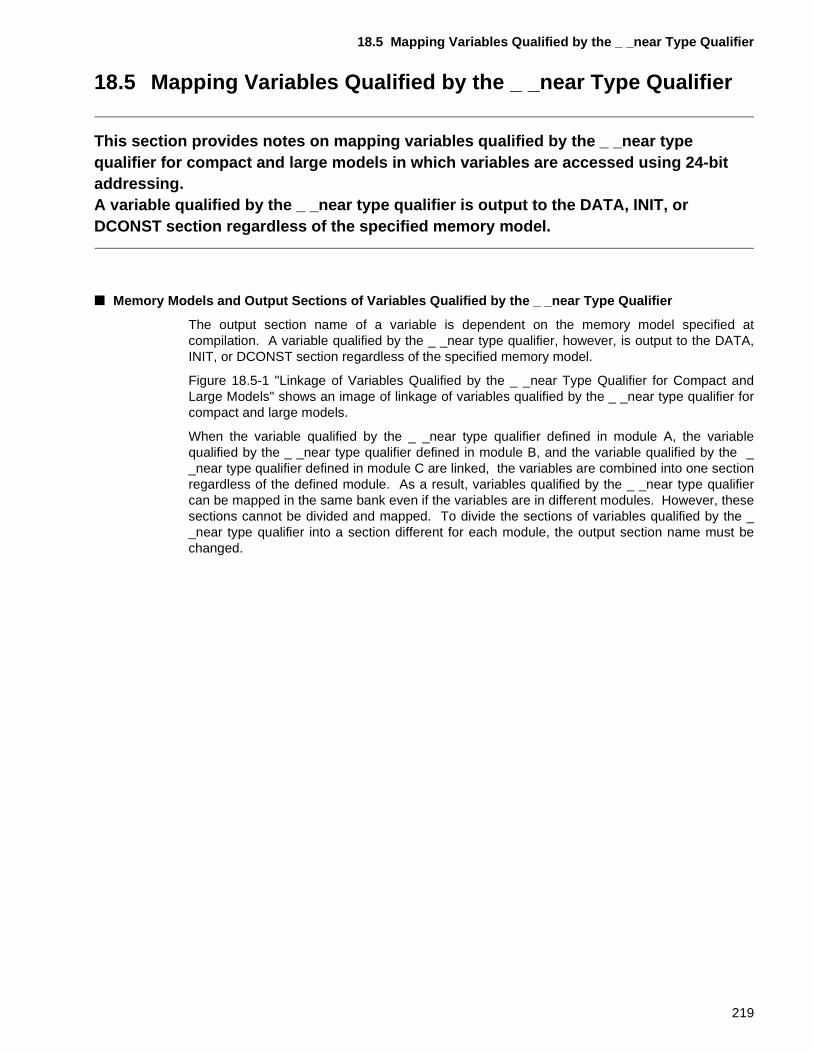
18.5 Mapping Variables Qualified by the _ _near Type Qualifier
18.5 Mapping Variables Qualified by the _ _near Type Qualifier
This section provides notes on mapping variables qualified by the _ _near type qualifier for compact and large models in which variables are accessed using 24-bit addressing.A variable qualified by the _ _near type qualifier is output to the DATA, INIT, or DCONST section regardless of the specified memory model.
■ Memory Models and Output Sections of Variables Qualified by the _ _near Type Qualifier
The output section name of a variable is dependent on the memory model specified atcompilation. A variable qualified by the _ _near type qualifier, however, is output to the DATA,INIT, or DCONST section regardless of the specified memory model.
Figure 18.5-1 "Linkage of Variables Qualified by the _ _near Type Qualifier for Compact andLarge Models" shows an image of linkage of variables qualified by the _ _near type qualifier forcompact and large models.
When the variable qualified by the _ _near type qualifier defined in module A, the variablequalified by the _ _near type qualifier defined in module B, and the variable qualified by the __near type qualifier defined in module C are linked, the variables are combined into one sectionregardless of the defined module. As a result, variables qualified by the _ _near type qualifiercan be mapped in the same bank even if the variables are in different modules. However, thesesections cannot be divided and mapped. To divide the sections of variables qualified by the __near type qualifier into a section different for each module, the output section name must bechanged.
219
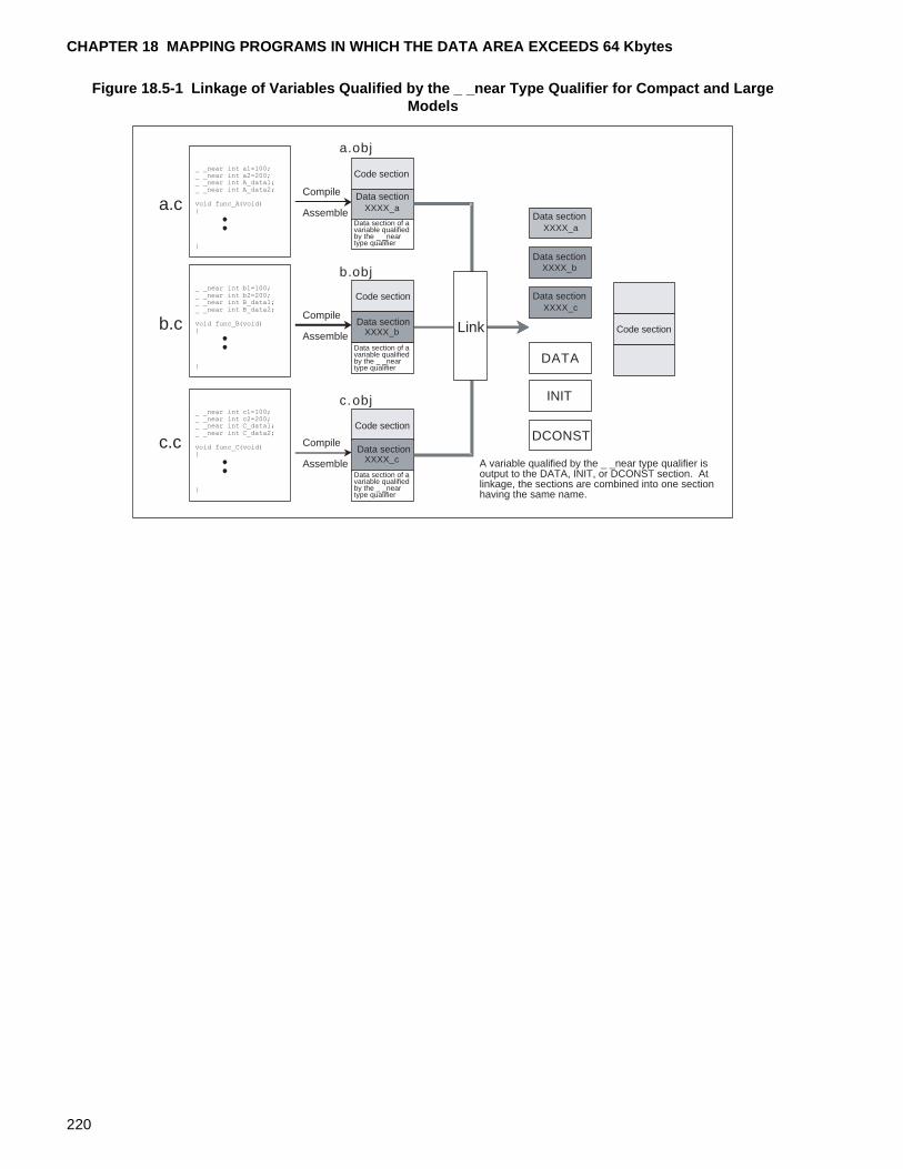
CHAPTER 18 MAPPING PROGRAMS IN WHICH THE DATA AREA EXCEEDS 64 Kbytes
Figure 18.5-1 Linkage of Variables Qualified by the _ _near Type Qualifier for Compact and Large Models
XXXX_a
XXXX_b
XXXX_c
XXXX_a
XXXX_b
XXXX_c
INIT
DATA
a.c
b.c
c.c
a.obj
b.obj
c.obj
DCONST
Data sectionCompile
Assemble
Compile
Assemble
Compile
Assemble
Data section
Data section
Data section
Data section
Data section
Code section
Code section
Code section
Code section
A variable qualified by the _ _near type qualifier is output to the DATA, INIT, or DCONST section. At linkage, the sections are combined into one section having the same name.
Link
Data section of a variable qualified by the _ _near type qualifier
Data section of a variable qualified by the _ _near type qualifier
Data section of a variable qualified by the _ _near type qualifier
_ _near int b1=100;_ _near int b2=200;_ _near int B_data1;_ _near int B_data2;
void func_B(void){
}
_ _near int a1=100;_ _near int a2=200;_ _near int A_data1;_ _near int A_data2;
void func_A(void){
}
_ _near int c1=100;_ _near int c2=200;_ _near int C_data1;_ _near int C_data2;
void func_C(void){
}
220
18.5 Mapping Variables Qualified by the _ _near Type Qualifier
■ Example of Mapping Variables Qualified by the _ _near Type Qualifier (for a Compact Model)
For compact and large models, variables are accessed using 24-bit addressing. Variablesqualified by the _ _near type qualifier, however, are accessed using 16-bit addressing on thepremise that the variables are mapped in the bank pointed to by the DTB.
The DATA and INIT sections must be allocated in the h’00 bank pointed to by the DTB.
Figure 18.5-2 Example of Mapping Variables Qualified by the _ _near Type Qualifier (for a Compact Model)
In this example, the h’ff bank is ROM area. The following sections are allocated in the h’ff bank:
• CODE (code area)
• DIRCONST (initial value area of a variable qualified by the _ _direct type qualifier)
• CONST_space1 (area of a variable qualified by the const type qualifier for module space1)
• CONST_space2 (area of a variable qualified by the const type qualifier for module space2)
• CONST_space3 (area of a variable qualified by the const type qualifier for module space3)
• DCONST (initial value area of a variable qualified by the _ _near type qualifier)
• DCONST_space1 (initial value area of a variable of module space1)
• DCONST_space2 (initial value area of a variable of module space2)
• DCONST_space3 (initial value area of a variable of module space3)
In this example, the h’00, h’01, h’02, and h’03 banks are RAM area. The following sections areallocated in the h’00 bank:
• IO_REG (I/O register variable area)
• DATA (variable area of a variable qualified by the _ _near type qualifier)
• INIT (variable area of an initialized variable qualified by the _ _near type qualifier)
• DIRDATA (variable area of a variable qualified by the _ _direct type qualifier)
I/O area
Register bank
DATA
INIT
DIRDATA
DIRINITSTACK
CODE
DCONST_space1
DIRCONST
CONST_space1
INTVECT
DTB
DPR
PCB
DCONST_space3
CONST_space3
DCONST_space2
CONST_space2
DATA_space2
INIT_space2
DATA_space3
INIT_space3
ROM area
RAM area
DCONST
DATA_space1
INIT_space1
h�ff ffff
h�ff ff54
h�ff 0000
h�00 0000
h�00 0180
h�00 0190
h�03 0000
h�02 0000
h�01 0000
@ -AL 0@ -ro ROM_AREA=0xFF0000/0xFFFFFF@ -ra RAM_sapce1=0x000190/0x000CFF@ -ra RAM_space2=0x010000/0x01FFFF@ -ra RAM_space3=0x020000/0x02FFFF@ -ra RAM_space4=0x030000/0x03FFFF@ -sc DATA/data/BYTE+INIT/data/BYTE+DIRDATA/dir/PAGE
+DIRINIT/dir/BYTE+*space1/data/BYTE=RAM_sapce1@ -sc *_space2/data/BYTE=RAM_space2@ -sc *_space3/data/BYTE=RAM_space3@ -sc STACK/stack/BYTE=RAM_space4@ -sc CODE/code/BYTE+DIRCONST/dirconst/BYTE
+CONST*/const/BYTE+DCONST*/const/BYTE+*/const/BYTE=ROM_AREA
@ -rg 0@ -m D:¥Softune¥*¥near_*¥LST¥near_*.mp1@ -pl 60@ -pw 132@ -alin D:¥Softune¥*¥near_*¥LST¥@ -alout D:¥Softune¥*¥near_*¥LST¥@ -na@ -Xals@ -Xalr@ -w 1@ -g@ -cwno@ -a@ -cpu MB90P678@ -o D:¥Softune¥*near_*¥ABS¥near_*.abs
221

CHAPTER 18 MAPPING PROGRAMS IN WHICH THE DATA AREA EXCEEDS 64 Kbytes
• DIRINIT (variable area of an initialized variable qualified by the _ _direct type qualifier)
• DATA_space1 (variable area of module space1)
• INIT_space1 (variable area of an initialized variable of module space1)
The following sections are allocated in the h’01 bank:
• DATA_space2 (variable area of module space2)
• INIT_space2 (variable area of an initialized variable of module space2)
The following section is allocated in the h’02 bank:
• DATA_space3 (variable area of module space3)
• INIT_space3 (variable area of an initialized variable of module space3)
The following section is allocated in the h’03 bank:
• STACK (user stack and system stack)
Refer to this example to allocate a section based on the system to be created.
222
INDEX
INDEX
The index follows on the next page.This is listed in alphabetic order.
223
INDEX
Index
Symbols
#define definition.................................................... 26#pragma ilm/noilm to set the interrupt level
in function, using........................................ 159#pragma inline is specified, when inline
expansion is not executed even though....... 53#pragma inline specification, executing inline
expansion using........................................... 54#pragma intvect/defvect to register interrupt
function, using............................................ 166_ _direct type qualifier and initialization of
DPR register .............................................. 145_ _direct type qualifier and initialization of
DTB register............................................... 144_ _far type qualifier and _ _near type qualifier,
specification of ............................................. 86_ _far type qualifier and output section of variable
qualified by const type ............................... 187_ _interrupt type qualifier to code interrupt
function, using............................................ 162_ _near type qualifier and _ _far type qualifier,
specification of ............................................. 86_ _set_il( ) to set interrupt level in function,
using .......................................................... 158
A
accessing I/O area register as variable from C program, operation for............................ 134
accessing I/O area using bit field and union .......... 44accessing system stack using
#pragma except/noexcept.......................... 107accessing system stack Using
#pragma ssb/nossb.................................... 105accessing variable and function defined in
C program from assembler program.......... 125accessing variable qualified by
_ _direct type qualifier................................ 143accessing variable using 24-bit addressing ......... 206accessing variable using direct addressing.......... 144allocating section of initialized variable ........ 179, 182area allocated on stack at function call .................. 48argument passing and stack usage size ................ 58argument structure passing.................................... 60automatic variable .................................................. 35automatic variable, variable Area of....................... 32
B
bank register and memory model......................... 174bit field definition and boundary alignment............. 41bit field of bit field length 0...................................... 41boundary alignment................................................ 41boundary alignment of fcc907................................ 40
C
calling function passing address of structure variable to which return value is to be passed ......................................................... 75
calling function passing taddress of union variable to which return value are to be passed ........ 78
calling function returning structure-type value........ 73calling function returning union-type value............. 77code section of medium and large model ............ 197code section of small and compact model ........... 195code section of small and medium model ............ 211coding assembler instruction using
_ _asm statement ........................................ 84coding assembler program................................... 124coding assembler program outside function ........ 128compact and large model, data section of ........... 214compact and large model, specifying
_ _near type qualifier in variable for........... 217compact model and code section of small ........... 195condition for passing structure address ................. 63CPU interrupt, enabling........................................ 157
D
data section of compact and large model ............ 214defining MB90678 I/O register ............................. 135defining variable using "const" type qualifier.......... 28definition and scope of automatic variable and
statically allocated variable .......................... 34definition of bit field of different type....................... 42disabling interrupt using _ _DI( ) .......................... 112dividing module and specifying
_ _far type qualifier in a function ................ 191
E
enabling interrupt using _ _EI( ) ........................... 113
224
INDEX
example of mapping function qualified _ _near type qualifier (for a medium model) ........... 203
example of mapping function qualified by _ _far type qualifier (for a large model) ................ 198
example of mapping function qualified by _ _far type qualifier (for a small model)................ 196
example of mapping variable qualified by _ _far type qualifier (for a large model) ................ 215
example of mapping variable qualified by _ _far type qualifier (for a small model)................ 212
example of mapping variable qualified by _ _near type qualifier (for a compact model)........... 221
extended function using #pragma.......................... 95extended type qualifier ........................................... 85external variable..................................................... 14external variable and automatic variable................ 35
F
F2MC-16 family interrupt...................................... 148F2MC-16 family memory mapping ....................... 132function call using 24-bit addressing .................... 190function call, stack statu at ..................................... 62function qualified by _ _far type qualifier, memory
model and output section of....................... 194function return value returned via A register .......... 68function return value returned via AL register ........ 67function returning pointer-type value...................... 70function returning structure-type value................... 71function returning union-type value ........................ 72function with _ _interrupt type qualifier................... 91function with _ _nosavereg type qualifier ............... 93function with static global variable, example of ...... 23function with static local variable, example of ........ 24
G
generated object of small and large model .......... 175generating interrupt vector tables using
#pragma intvect/defvect............................. 109
H
hardware setting for interrupt, required ................ 150hardware that does not support mirror
ROM function, mapping variable qualified by const type qualifier for............. 184
I
I flag to enable interrupt for entire system, using .......................................................... 160
including assembler program having multiple instruction in function ................................. 127
initial value and variable area for external variable ........................................................ 17
initialization at execution ........................................ 19initialization of DPR register and _ _direct type
qualifier ...................................................... 145initialization of DTB register and _ _direct type
qualifier ...................................................... 144initialized variable and initialization at execution.... 19initialized variable, allocating section of ....... 179, 182initializing resource............................................... 153inline expansion of function.................................... 52inline expansion of function, condition for .............. 55inline expansion using #pragma inline ................... 97inserting assembler program using
#pragma asm/endasm ................................. 96interrupt control register, setting........................... 154interrupt function that switch register bank
without saving work register, coding of ...... 164interrupt handling in F2MC-16 family ................... 148
L
large model and code section of medium ............ 197large model and generated object of small .......... 175
M
mapping aariable qualified by _ _direct type qualifier............................................... 145
mapping function qualified _ _near type qualifier (for a medium model), example of ............. 203
mapping function qualified by _ _far type qualifier (for a large model), example of .................. 198
mapping function qualified by _ _far type qualifier (for a small model), example of.................. 196
mapping variable qualified by _ _far type qualifier (for a large model), example of .................. 215
mapping variable qualified by _ _far type qualifier (for a small model), example of.................. 212
mapping variable qualified by _ _near type qualifier (for a compact model), example of ............ 221
mapping variable qualified by const type qualifier for hardware that does not support mirror ROM function...................... 184
mapping, memory area into ..................................... 6MB90678 I/O register, accessing ......................... 138medium and large model, specifying
_ _near type qualifier in function for........... 200memory model and bank register......................... 174
225
INDEX
memory model and output section of function qualified _ _near type qualifier ..... 202
memory model and output section of function qualified by _ _far type qualifier.... 194
memory model and output section of variable qualified by _ _far type qualifier ................. 210
memory model and output section of variable qualified by _ _near type qualifier .............. 219
memory model of fcc907...................................... 172
N
normal argument passing....................................... 59note on using mirror ROM function .............. 180, 183numeric constant and #define definition................. 26
O
other additional built-in function ........................... 115output a nop istruction using _ _wait_nop( ) ........ 116output section and specification of
-ramconst option ........................................ 185output section of function qualified _ _near
type qualifier and memory model............... 202output section of variable qualified by _ _far
type qualifier and memory model............... 210output section of variable qualified by _ _near
type qualifier and memory model............... 219output section of variable qualified by const
type and _ _far type qualifier...................... 187
P
passing structure address, condition for ................ 63program component ................................................. 4
R
resource operation, starting ................................. 156return value of function........................................... 66returning function return value via stack ................ 69
S
sample I/O register file provided by fcc907 .......... 134scope of automatic variable and statically
allocated variable......................................... 34setting interrupt level using _ _set_il( )................. 114setting register bank using
#pragma register/noregister....................... 103signed 16-bit multiplication using _ _mul( ) .......... 117signed 32-bit/signed 16-bit division using
_ _div( ) ...................................................... 119
signed 32-bit/signed 16-bit remaind calculation using _ _mod( ) .......................................... 121
signed bit field ........................................................ 43small and compact model, specifying _ _far
type qualifier in a function for ..................... 191small and medium model, code section of ........... 211small and medium model, specifying _ _far
type qualifier in a variable for ..................... 208specification of _ _near type qualifier and _ _far
type qualifier................................................. 86specification of -ramconst option and
output section............................................. 185specify mapping address ....................................... 99specifying _ _far type qualifier in a function
and dividing module ................................... 191specifying _ _far type qualifier in a function for
small and compact model .......................... 191specifying _ _far type qualifier in a variable for
small and medium model ........................... 208specifying _ _far type qualifier in variable
depending on access frequency ................ 208specifying _ _near type qualifier in function
for medium and large model ...................... 200specifying _ _near type qualifier in variable
for compact and large model ..................... 217specifying interrupt level using
#pragma ilm/noilm...................................... 101stack state when function call are nested .............. 50stack status at function call .................................... 62stack usage size..................................................... 58statically allocated variable and variable area
in RAM ......................................................... 33structure address passing ...................................... 61system stack, setting............................................ 151
U
unsigned 16-bit multiplication using _ _mulu( ) .... 118unsigned 32-bit/unsigned 16-Bit remaind
calculation using _ _modu( ) ...................... 122unsigned 32-bit/usigned 16-bit division using
_ _divu( ) .................................................... 120using #pragma section to change section name
and specify mapping address ...................... 99using interrupt-related built-in function to
add function ............................................... 111using mirror ROM function, note on ............. 180, 183
V
variable area for external variable.......................... 17variable area in RAM.............................................. 33
226
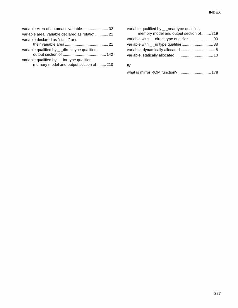
INDEX
variable Area of automatic variable........................ 32variable area, variable declared as "static" ............ 21variable declared as "static" and
their variable area ........................................ 21variable qualified by _ _direct type qualifier,
output section of ........................................ 142variable qualified by _ _far type qualifier,
memory model and output section of......... 210
variable qualified by _ _near type qualifier, memory model and output section of......... 219
variable with _ _direct type qualifier ....................... 90variable with _ _io type qualifier ............................. 88variable, dynamically allocated ................................ 8variable, statically allocated ................................... 10
W
what is mirror ROM function?............................... 178
227

INDEX
228
CM42-00327-1E
FUJITSU SEMICONDUCTOR • CONTROLLER MANUAL
F2MC-16 FAMILY
16-BIT MICROCONTROLLER
EMBEDDED C PROGRAMMING MANUAL
FOR fcc907
October 2000 the first edition
Published FUJITSU LIMITED Electronic Devices
Edited Technical Communication Dept.

FUJITSU SEMICONDUCTOR F2MC-16 FAMILY 16-BIT MICROCONTROLLER EMBEDDED C PROGRAMMING MANUAL FOR fcc907