16-Bit, 200-kHz PCI Data Acquisition Boards · Measurement Computing 1(508) 946-5100 infomccdaq.com...
12
Measurement Computing (508) 946-5100 1 [email protected] mccdaq.com The DaqBoard/2000 Series plug-in boards provide cost-effective, high-speed data acquisition DaqBoard/2000 Series 16-Bit, 200 kHz PCI Data Acquisition Boards Features • Three DaqBoard/2000 Series PCI boards are available • 16-bit, 200 kHz A/D converter • 8 differential or 16 single-ended analog inputs (software selectable per channel) • Expandable up to 256 analog input channels, while maintaining 200 kHz (5 µs per channel) scan rate • Up to four boards can be installed into one PC for up to 1024 analog input channels • 100% digital calibration • 512 location channel/gain FIFO, capable of scanning all channels, in- cluding 256 analog expansion chan- nels and digital/counter channels, at 5 µs per channel • DMA bus mastering for synchronous analog I/O, digital I/O, and counter inputs • Trigger modes include analog, digital, and software, with <5 µs latency • Virtually infinite pre-trigger buffer* • Up to four 16-bit, 100 kHz analog out- puts with infinite continuous waveform output capability* • 40 digital I/O lines, can be scanned synchronously or asynchronously with analog inputs • Digital I/O is expandable up to 272 lines, including optional isolation and relay closure • Four counter/pulse input channels can be scanned synchronously or asynchro- nously with analog inputs • Two timer/pulse output channels Signal Conditioning Options • Signal conditioning and expansion options for thermocouples, strain gages, accelerometers, isolation, RTDs, etc. — over 40 options in all Software • Includes DaqView Out-of-the-Box soft- ware application for effortless data logging and analysis • Comprehensive drivers for DASYLab ® , NI LabVIEW ® , Visual C++ ® , Visual C# ® , Visual Basic ® , and Visual Basic ® .NET • DaqCal software application for easy user calibration • Supported Operating Systems: Windows 7/Vista/XP SP2, 32-bit or 64-bit * Limited only by available PC RAM and hard disk space The DaqBoard/2000 Series sets the price/ performance benchmark for high-speed, multifunction plug-and-play data ac- quisition for PCI bus computers. The DaqBoard/2000 Series hardware design offers all of the features normally found on significantly more expensive boards, including 16-bit, 200 kHz A/D, 100% digital calibration, bus mastering, two or four 16-bit, 100 kHz D/A converters, 40 digital I/O lines, four counters, and two timers. DaqBoard/2000 Series is supported by a growing family of over 40 signal condition- ing and expansion options, offering signal conditioning for thermocouples, RTDs, accelerometers, isolation, high-voltage, strain gages, and much more. Up to 528 channels of analog and digital I/O can be accessed using one DaqBoard/2000, while maintaining the 5 µs per channel update rate. Up to four DaqBoard/2000s can be installed into one PC. In total, the DaqBoard/2000 Series sets the industry standard for plug-and-play PCI data acquisition. Synchronous I/O for High-Speed Applications The DaqBoard/2000 Series sets a new standard with its ability to make analog measurements, read digital inputs, and read counter inputs, while synchronously generating up to four analog outputs and/or a 16-bit digital pattern output. Most other boards require CPU interaction to access I/O other than analog input, mak- ing it impossible to generate time-critical analog waveforms or digital patterns. With the DaqBoard/2000 Series, the true power of todays’ PCI-based PCs can be unleashed. The same synchronous features of the DaqBoard extend to its family of DBK signal conditioning and expansion options. Up to 256 analog input channels and 272 (256, P2 only) digital I/O channels can also be accessed synchronously to one another, with precise and deterministic channel- to-channel timing. Up to four DaqBoards can be installed in one PC, quadrupling the channel capacity to over 1,000 analog input channels, 1,000 digital I/O channels and 16 high-speed analog output channels.
Transcript of 16-Bit, 200-kHz PCI Data Acquisition Boards · Measurement Computing 1(508) 946-5100 infomccdaq.com...

Measurement Computing (508) 946-5100 1 [email protected] mccdaq.com
The DaqBoard/2000 Series plug-in boards provide cost-effective, high-speed data acquisition
DaqBoard/2000 Series16-Bit, 200 kHz PCI Data Acquisition Boards
Features• Three DaqBoard/2000 Series PCI boards
are available• 16-bit, 200 kHz A/D converter• 8 differential or 16 single-ended analog
inputs (software selectable per channel)• Expandable up to 256 analog input
channels, while maintaining 200 kHz (5 µs per channel) scan rate
• Up to four boards can be installed into one PC for up to 1024 analog input channels
• 100% digital calibration• 512 location channel/gain FIFO,
capable of scanning all channels, in-cluding 256 analog expansion chan-nels and digital/counter channels, at 5 µs per channel
• DMA bus mastering for synchronous analog I/O, digital I/O, and counter inputs
• Trigger modes include analog, digital, and software, with <5 µs latency
• Virtually infinite pre-trigger buffer*• Up to four 16-bit, 100 kHz analog out-
puts with infinite continuous waveform output capability*
• 40 digital I/O lines, can be scanned synchronously or asynchronously with analog inputs
• Digital I/O is expandable up to 272 lines, including optional isolation and relay closure
• Four counter/pulse input channels can be scanned synchronously or asynchro-nously with analog inputs
• Two timer/pulse output channels
Signal Conditioning Options• Signal conditioning and expansion
options for thermocouples, strain gages, accelerometers, isolation, RTDs, etc. — over 40 options in all
Software• Includes DaqView Out-of-the-Box soft-
ware application for effortless data logging and analysis
• Comprehensive drivers for DASYLab®, NI LabVIEW®, Visual C++®, Visual C#®, Visual Basic®, and Visual Basic® .NET
• DaqCal software application for easy user calibration
• Supported Operating Systems: Windows 7/Vista/XP SP2,
32-bit or 64-bit
* Limited only by available PC RAM and hard disk space
The DaqBoard/2000 Series sets the price/performance benchmark for high-speed, multifunction plug-and-play data ac-quisition for PCI bus computers. The DaqBoard/2000 Series hardware design offers all of the features normally found on significantly more expensive boards, including 16-bit, 200 kHz A/D, 100% digital calibration, bus mastering, two or four 16-bit, 100 kHz D/A converters, 40 digital I/O lines, four counters, and two timers.
DaqBoard/2000 Series is supported by a growing family of over 40 signal condition-ing and expansion options, offering signal conditioning for thermocouples, RTDs, accelerometers, isolation, high-voltage, strain gages, and much more. Up to 528 channels of analog and digital I/O can be accessed using one DaqBoard/2000, while maintaining the 5 µs per channel update rate. Up to four DaqBoard/2000s can be installed into one PC.
In total, the DaqBoard/2000 Series sets the industry standard for plug-and-play PCI data acquisition.
Synchronous I/O for High-Speed ApplicationsThe DaqBoard/2000 Series sets a new standard with its ability to make analog measurements, read digital inputs, and read counter inputs, while synchronously generating up to four analog outputs and/or a 16-bit digital pattern output. Most other boards require CPU interaction to access I/O other than analog input, mak-ing it impossible to generate time-critical analog waveforms or digital patterns. With the DaqBoard/2000 Series, the true power of todays’ PCI-based PCs can be unleashed.
The same synchronous features of the DaqBoard extend to its family of DBK signal conditioning and expansion options. Up to 256 analog input channels and 272 (256, P2 only) digital I/O channels can also be accessed synchronously to one another, with precise and deterministic channel-to-channel timing. Up to four DaqBoards can be installed in one PC, quadrupling the channel capacity to over 1,000 analog input channels, 1,000 digital I/O channels and 16 high-speed analog output channels.

Measurement Computing (508) 946-5100 2 [email protected] mccdaq.com
DaqBoard/2000 SeriesGeneral Information
Signal I/OOne 100-pin connector on the DaqBoard/2000 Series provides access to all of the input and output signals. Unlike other multifunction boards that require multiple PC slots in order to access all of the I/O, careful design of the DaqBoard/2000 Series accommodates all I/O using one cable, and utilizing a single PCI slot.
The 100-pin DaqBoard/2000 Series I/O con-nector, P4, is logically divided into three sub-ports, P1, P2, and P3. P1, the analog input port, contains all of the analog input channels, as well as the sequencer control signals for accessing external analog input options. All analog expansion options at-tach to the P1 port. P2, the general purpose digital I/O port, can be used directly to control and monitor 24 digital I/O lines. P2 can also function as the digital I/O expansion port, whereby the 24 lines are exclusively used to control external digital DBK expansion options, for up to 256 lines of digital input or output. P3 contains an additional 16-bit digital I/O port, as well as the counter inputs, timer outputs, and analog outputs. Several options are avail-able to provide easy user access to all of the I/O signals on P4.
Analog Input (P1)The DaqBoard/2000 Series has a 16-bit, 200 kHz A/D coupled with 16 single-ended, or 8 differential analog inputs. Thirteen software programmable ranges provide inputs from ±10V to ±156 mV full scale. Each channel can be software-configured for a different range, as well as for single-ended or differential, and unipolar or bipolar input. Beyond the 16 built-in analog inputs, the user can expand the DaqBoard/2000 Series
up to 256 analog inputs using external DBK signal conditioning and expansion options. As with the on-board channels, expansion channels are scanned at the same 5 µs/chan-nel rate (200 kHz), and most are software- programmable for range. There is no speed penalty for scanning expansion channels versus built-in channels. The DBK expan-sion options offer a wide variety of signal measurements, including thermocouples, RTDs, strain gages, accelerometers, high voltage, isolation, current, and much more.
ScanningThe DaqBoard/2000 Series has an on-board scan sequencer that permits the user to select any combination of up to 512 channel/range combinations. The sequencer scans all channels contained in the sequence at the fastest rate of 5 µs/channel, thereby minimizing the time-skew from channel-to-channel. The user can also set the time between scan groups, from 0 to 6 hours. In addition to scanning analog inputs, the sequencer can scan digital inputs and counter inputs.
Bus Mastering DMAThe DaqBoard/2000 Series supports Bus Mastering DMA, which allows analog and digital/counter input data, as well as analog and digital output data to flow between the PC and the DaqBoard/2000 Series without consuming valuable CPU time. The driver supplied with the DaqBoard/2000, as well as all other third-party software support such as DASYLab® and NI LabVIEW®, automatically utilize Bus Mastering DMA to efficiently conduct I/O from the PC to the DaqBoard.
Multifunction I/OFeature /2001 /2000 /2005
Analog inputs (16 bit/200 kHz) 16 16 16
Analog outputs (16 bit/100 kHz) 4 2 —
Digital I/O 40 40 40
Freq./pulse I/O 6 6 6
DaqBoard/2000™ Series Selection Chart
TriggeringTriggering can be the most critical aspect of a data acquisition application. The DaqBoard/2000 Series supports a full com-plement of trigger modes to accommodate any measurement situation.
Hardware Analog Triggering. Many data acquisition boards claim analog triggering, but rely on the PC to take readings and make a decision, which leads to uncer-tain and potentially long latencies. The DaqBoard/2000 Series uses true analog triggering, whereby the trigger level programmed by the user sets an analog DAC, which is then compared in hardware to the analog input level on the selected channel. The result is analog trigger latency which is guaranteed to be less than 5 µs, significantly shorter than most data acqui-sition boards. Any analog channel can be selected as the trigger channel, including built-in or expansion channels. The user can program both the trigger level, as well as the edge (rising or falling).
Digital and Pattern Triggering (P1). A sepa-rate digital trigger input line is provided, allowing TTL-level triggering, again with latencies guaranteed to be less than 5 µs. Both the logic levels (1 or 0), as well as the edge (rising or falling), can be programmed for the discrete digital trigger input.
Software-Based Triggering. Software-based triggering differs from the modes described above because the readings, analog, digital, or counter, are interrogated by the PC to detect the trigger event, not in the hardware as de-scribed above. The advantage of this mode is to permit triggering based on more complex situations, such as on a specific temperature, which was derived from the acquisition of

Measurement Computing (508) 946-5100 3 [email protected] mccdaq.com
DaqBoard/2000 SeriesGeneral Information
DAC OUT
SIGNALI/O
32-bitdata and
address bus
PC (
PCI)
Bus
P4
ANALOG IN
ANALOGCONTROL
DIGITALCONTROL
DIGITAL I/O
24 Three 8-bit digital I/O ports
17 One 16-bit digital I/O port,One DAC pacer clock
6 Four 16-bit counter inputs,Two 16-bit timer outputs
2 One TTL trigger input,One analog input pacer clock
7 Four external channel select,Two external gain select,
One SS&H
16 Inputprotection
FIFOdata
bufferProgrammable
sequencertimebase
5 �s to 6 hours
Systemcontroller
ConfigurablePLD
PCIcontroller
ConfigurableEEPROM
16-bitdigital-to-analog
converter
External MUXcontrol
8 DE/16 SEanalog input
512-steprandom accesschannel/gain
sequencer
Dual 11-bittriggerDACs
Analogtrigger
200-kHzinput clock
x1, 2, 4, 8Programmablegain amplifierx16, 32, 64
Gain andoffsetamplifier
Sequencer reset
16-bit, 200-kHzanalog-to-digitalconverterP1
P1
P1
P3
P3
P2
P3
MUX
A
A
100-kHzoutputclock
2 channels on DaqBoard/2000,4 channels on DaqBoard/2001,
none included on DaqBoard/2005
DaqBoard/2000, /2001, and /2005 Block Diagram
at least two analog measurements, plus the calculation of the measured temperature us-ing linearization algorithms.
The DaqBoard/2000 Series also supports digital pattern triggering, whereby the user can designate any of the digital input ports as the trigger port. The programmed digital pattern, including the ability to mask or ignore specific bits, is then com-pared to the actual input until a match is detected, after which the sequencer begins the scan sequence.
Triggering can also be programmed to occur when one of the counters reaches, exceeds, or is within a programmed level. Any of the built-in counter/ totalizer channels can be programmed as a trigger source.
Normally software-based triggering results in long latencies from the time that a trig-ger condition is detected, until the actual capturing of data commences. However,
the DaqBoard/2000 Series circumvents this undesirable phenomenon by use of pre-trigger data. Specifically, when software-based triggering is employed, and the PC detects that a trigger condition has occurred, (which may be thousands of readings later than the actual occur-rence of the signal), the DaqBoard driver automatically looks back to the location in memory where the actual trigger-causing measurement occurred. The acquired data that is presented to the user actually begins at the point where the trigger-causing measurement occurs. The latency in this mode is equal to one scan cycle.
Stop Trigger. Any of the software trigger modes described above can also be used to stop an acquisition. Thus an acquisition can be programmed to begin on one event, such as a temperature level, and then can stop on another event, such as a digital pattern.
Pre- and Post-Triggering Modes. Six modes of pre- and post-triggering are supported, providing a wide variety of options to accommodate any measurement require-ment. When using pre-trigger, the user must use software-based triggering to initiate an acquisition.
No pre-trigger, post-trigger stop event. This, the simplest of modes, acquires data upon receipt of the trigger, and stops acquiring upon receipt of the stop-trigger event.
Fixed pre-trigger with post-trigger stop event. In this mode, the user specifies the number of pre-trigger readings to be ac-quired, after which, acquisition continues until a stop-trigger event occurs.
No pre-trigger, infinite post-trigger. No pre-trigger data is acquired in this mode. Instead, data is acquired beginning with the trigger event, and is terminated when the operator issues a command to halt the acquisition.

Measurement Computing (508) 946-5100 4 [email protected] mccdaq.com
DaqBoard/2000 SeriesGeneral Information
Fixed pre-trigger with infinite post-trigger. The user specifies the amount of pre- trigger data to acquire, after which the system continues to acquire data until the program issues a command to halt acquisition.
Variable pre-trigger with post-trigger stop event*. Unlike the previous pre-trigger modes, this mode does not have to satisfy the pre-trigger number of readings before recognizing the trigger event. Thus the number of pre-trigger readings acquired is variable and dependent on the time of the trigger event relative to the start. In this mode, data continues to be acquired until the stop trigger event is detected.
Variable pre-trigger with infinite post- trigger*. This is similar to the mode described above, except that the acquisition is terminated upon receipt of a command from the program to halt the acquisition.
CalibrationEvery range on the DaqBoard/2000 Series is calibrated from the factory using a digital calibration method. This method works by storing a correction factor for each range on the DaqBoard/2000 Series at the time of calibration. Whenever a particular range is selected, the appropriate calibra-tion constant is automatically applied to a compensating DAC, thereby calibrating the specific range. The result is that readings generated by the A/D are already calibrated, and do not require additional processing.
This is significantly better than other boards, that merely adjust the readings in software after they are transferred to the PC. That method has the disadvantage of reducing the dynamic range of the A/D, and can adversely affect the speed at which the PC can obtain a calibrated reading.
The DaqBoard/2000 Series also has a user-cal mode, whereby the user can ad-just the calibration of the board in their system, without destroying the factory calibration supplied with the board. This is accomplished by having 2 distinct cali-bration tables in the DaqBoard/2000 Series on-board EPROM, one which contains the factory cal, and the other which is available for user calibration.
DaqBoard/2000 Series Scanning Example
Any of the digital input portscan also be sampled alongwith the analog inputs
Analog expansion channels(up to 256) are sampled at thesame rate as on-board channels
5 �s
t
Programmable,from 5 �s up to
6 hours
Scan groupAll channels within a scan group aremeasured at a fixed 5 �s/channel
Unipolar or bipolar operationcan be programmed for eachchannel dynamically by thesequencerGain can be programmed foreach channel dynamically bythe sequencerChannels can be sampleddynamicallyby the sequencer
t
Any of the four counter inputscan be scanned along withanalog and digital inputs
Channel #2 #4 C1 #2 D2 #18 #164 #26Gain x1 x8 x2 x100 x10 x1000
Unipolar Uni Uni Uni Bi Bi Unior bipolar SE DE SE DE DE SE or DE
Channel-Scanning Flexibility The DaqBoard/2000 Series offers a 512-location scan sequencer that allows you to select each channel and associated input amplifier gain at random. The sequencer circuitry circumvents a major limitation encountered with many plug-in data acqui-sition boards—a drastic reduction in the scan rate for external expansion channels. All DaqBoard/2000 Series channels, including the 528 potential expansion channels, are scanned at 100K or 200 kHz (1 or 5 µs/channel), software programmable per channel. In addition, the digital and frequency inputs can be scanned using the same scan sequence employed for analog inputs, enabling the time correlation of acquired digital data to acquired analog data. The DaqBoard/2000 Series permits each scan group, which can contain up to 512 channel/gain combinations, to be repeated immediately or at programmable intervals of up to 6 hours. Within each scan group, consecutive channels are measured at a fixed 5 µs/channel rate.
each D/A output can continuously output a waveform, which can be read from PC RAM or a file on the hard disk. In addition, a program can asynchronously output a value to either of the D/As for non-waveform applications, presuming that the D/A is not already being used in the waveform output mode. Additional low-speed D/A channels can be added to the DaqBoard through the use of the DBK2 analog output option card.
Analog Output (P3)DaqBoard/2000, & /2001 OnlyTwo or four 16-bit, 100 kHz analog output channels are built into the DaqBoard/2000 Series, with an output from -10V to +10V. These outputs are entirely separate from the D/As which are used to determine analog trigger level (some data acquisition board suppliers confusingly refer to trigger D/As as if they are available to the user). Through the use of Bus Mastering DMA,
* Using one of the programming languages

Measurement Computing (508) 946-5100 5 [email protected] mccdaq.com
DaqBoard/2000 SeriesGeneral Information
When used to generate waveforms, the D/As can be clocked in several different modes. Each D/A can be separately selected to be clocked from one of the sources described below.
Asynchronous Internal Clock. The on-board programmable clock can generate updates ranging from 1.5 Hz to 100 kHz, independent of any acquisition rate.
Synchronous Internal Clock. The rate of analog output update can be synchronized to the acquisition rate derived from 100 kHz to once every 5.96 hours.
Asynchronous External Clock. A user- supplied external input clock can be used to pace the D/A, entirely independent of analog inputs.
Synchronous External Clock. A user- supplied external input clock can pace both the D/A and the analog input.
Digital Pattern Generation (P3)The DaqBoard/2000 Series supports digital pattern generation via Bus Mastering DMA on the 16-bit high-speed digital I/O port. In the same manner as Analog Output, the digital pattern can be read from PC RAM or a file on the hard disk. Digital pattern gen-eration is clocked in the same four modes as described above with analog output*.
Digital Inputs and Outputs (P2, P3)Forty TTL-level digital I/O lines are in-cluded in the DaqBoard/2000 Series. They are divided into three 8-bit ports (P2) and one 16-bit port (P3). The P2 ports can be programmed in 8-bit groups as either in-put or output. The 16-bit P3 port can be programmed as all inputs or all outputs. Ports programmed as inputs can be part of the scan group and scanned along with other analog and digital input channels, or can be asynchronously accessed via the PC at any time, including when a scanned acquisition is occurring.
Product Description CapacityDBK1 16-connector BNC interface module 16 connectors
DBK2 D/A voltage-output card 4 channels
DBK4 Dynamic signal-input card 2 channels
DBK5 Current output card 4 channels
DBK7 Frequency-to-voltage input card 4 channels
DBK8 High-voltage input card 8 channels
DBK9 RTD measurement card 8 channels
DBK10 Expansion-card enclosure module 3 cards
DBK11A Screw-terminal card 40 terminals
DBK15 Universal current/voltage input card 16 channels
DBK16 Strain gage measurement card 2 channels
DBK17 Simultaneous sample and hold card 4 channels
DBK18 Low-pass filter card 4 channels
DBK20 Digital I/O card (screw-terminal connectors) 48 channels
DBK21 Digital I/O card (male DB37 connectors) 48 channels
DBK23 Optically isolated digital-input module 24 channels
DBK24 Optically isolated digital-output module 24 channels
DBK25 Relay output card 8 channels
DBK30A Rechargeable battery/excitation module 14.4 or 28.8 VDC
DBK32A Auxiliary power supply card ±15 VDC @ 500 mA
DBK41 Analog expansion enclosure module 10 cards
DBK42 5B isolated signal-conditioning module 16 channels
DBK43A Strain gage module 8 channels
DBK44 5B isolated signal conditioning card 2 channels
DBK45 SS&H card with low-pass filter 4 channels
DBK48 8B isolated signal-conditioning module 16 channels
DBK55 Frequency-to-voltage input module 8 channels
DBK60 3-slot expansion module w/customizable panels 3 cards
DBK65 Transducer interface module 8 channels
DBK80 Differential voltage input card with excitation output 16 channels
DBK81 TC/mV card with screw-terminal connections 7 channels
DBK82 TC/mV card with screw-terminal connections 14 channels
DBK83 TC/mV card with external screw-terminal Pod and 3 ft. cable 14 channels
DBK84 TC/mV module with mini TC connector jacks 14 channels
DBK85 Differential voltage input module 16 channels
DBK200 Adapter board for analog inputs P1Screw-terminal adapter board, solder locations for user-supplied resistors
DBK202 and R/C networks, with three expansion ports 120 terminals, P1, P2, P3
DBK203A Same as DBK202 adapter board with a rugged metal enclosure 120 terminals, P1, P2, P3
DBK206 Adapter board with removable screw-terminals with three expansion ports 120 terminals, P1, P2, P3
DBK207 5B-isolated analog input signal conditioning board with two expansion ports P1 (2)
DBK207/CJC Same as DBK207 plus on-board, cold-junction compensation; two expansion ports P1 (2)Opto-22® signal conditioning board for isolated (solid-state-relay) digital I/O,
DBK208 with two P2 digital I/O expansion ports P2 (2)
DBK209 Same as DBK201 but rack and DIN-rail mountable with optional kits P1, P2, P3
DBK210 Isolated high-density digital I/O board 32 channels
DBK213 Screw-terminal and expansion card module; 120 terminals, P1, P2, P3 48 channels
DBK214 16-connector BNC interface module; 120 terminals, P1, P2, P3 16 channels
DaqBoard/2000 Series Signal Conditioning & Expansion Options

Measurement Computing (508) 946-5100 6 [email protected] mccdaq.com
DaqBoard/2000 SeriesGeneral Information & Expansion Options
In addition, the P2 ports can be expanded up to 256 digital I/O lines using external DBK digital options. These options are available as TTL-level I/O, relay output, or optically isolated input and output. Whenever expansion digital I/O is attached to the DaqBoard/2000 Series, the P2 I/O lines are no longer user-programmable, and are instead used to communicate with the digital expansion options.
Counter Inputs (P3)Four 16-bit counters are built into the DaqBoard/2000, each capable of counting up to 65,536 TTL-level transitions. Each of the four counters will accept frequency inputs up to 10 MHz, and can be configured for pulse count or totalize mode. The counters can also be cascaded, allowing over four billion counts to be accumulated. As with all other inputs to the DaqBoard/2000 Series, the counter inputs can be read asynchronously under program control, or synchronously as part of an analog and digital scan group.
Timer Outputs (P3)Two 16-bit timer outputs are built into the DaqBoard/2000, each capable of generating different square waves with a programmable frequency range from 16 Hz to 1 MHz.
Multiple DaqBoards per PCAll of the features described for the DaqBoard/2000 can be repli-cated with up to four DaqBoard/2000s installed in the same PC. The serial number on each DaqBoard/2000 is used to differentiate one from another, and a user-selected name can be assigned to each board for easy program documentation. Thus, with four boards installed along with DBK expansion options, over 1,000 analog input channels and over 1,000 digital I/O channels could be accessed from one PC. When multiple boards are installed, all boards can be operated synchronously.
DBK213 Expansion ModuleThe DBK213 module provides screw- terminal access plus expansion slots for the DaqBoard/2000 Series. The top of the DBK213 is easily removed to reveal screw-terminal connections that provide access to all analog and digital I/O from the host data acquisition board. Also included with the DBK213 are three expansion slots that can accommodate any DBK analog or digital expansion and signal conditioning cards.
DBK214 Expansion ModuleThe DBK214 module provides 16 BNC connectors for accessing analog I/O, digital I/O, or counter/timer signals. In addition, screw- terminal connections for all signals are accessed by removing the DBK214’s top cover. Eight of the BNC connectors are pre-defined as analog inputs and are jumper selectable as single ended or differential. Another eight BNC connectors can be configured by the user on a per channel basis as an analog input or output, digital I/O, or counter/timer channels.
* When digital pattern generation is used, one of the analog output channels is limited to asynchronous output mode
Measurement Computing (508) 946-5100 7 [email protected] mccdaq.com
P1
To CA-195 cable
(P4)
DBK209 P3
P2
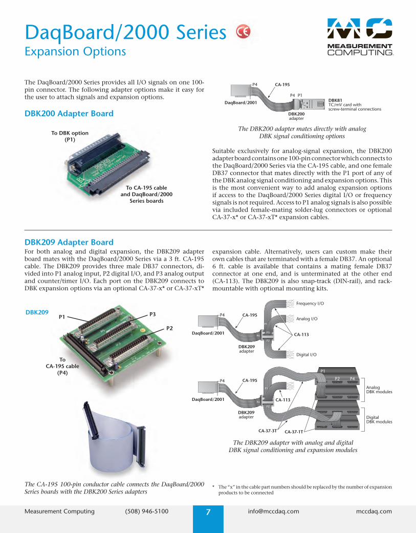
DBK209 Adapter BoardFor both analog and digital expansion, the DBK209 adapter board mates with the DaqBoard/2000 Series via a 3 ft. CA-195 cable. The DBK209 provides three male DB37 connectors, di-vided into P1 analog input, P2 digital I/O, and P3 analog output and counter/timer I/O. Each port on the DBK209 connects to DBK expansion options via an optional CA-37-x* or CA-37-xT*
The DBK209 adapter with analog and digital DBK signal conditioning and expansion modules
CA-113
P2 P4
P1
CA-37-3T
P4
P4
CA-195
CA-195
DBK209adapter
DBK209adapter
P4
DigitalDBK modules
Frequency I/O
Analog I/O
Digital I/O
DaqBoard/2001
DaqBoard/2001
AnalogDBK modules
CA-37-1T
P3
P1
P2
P3
P2
P4
P1
CA-113
expansion cable. Alternatively, users can custom make their own cables that are terminated with a female DB37. An optional 6 ft. cable is available that contains a mating female DB37 connector at one end, and is unterminated at the other end (CA-113). The DBK209 is also snap-track (DIN-rail), and rack-mountable with optional mounting kits.
* The “x” in the cable part numbers should be replaced by the number of expansion products to be connected
To DBK option (P1)
To CA-195 cable and DaqBoard/2000
Series boards
The DaqBoard/2000 Series provides all I/O signals on one 100-pin connector. The following adapter options make it easy for the user to attach signals and expansion options.
DBK200 Adapter Board
P4 CA-195
DBK200adapter
DaqBoard/2001
P4 P1DBK81TC/mV card withscrew-terminal connections
The DBK200 adapter mates directly with analog DBK signal conditioning options
Suitable exclusively for analog-signal expansion, the DBK200 adapter board contains one 100-pin connector which connects to the DaqBoard/2000 Series via the CA-195 cable, and one female DB37 connector that mates directly with the P1 port of any of the DBK analog signal conditioning and expansion options. This is the most convenient way to add analog expansion options if access to the DaqBoard/2000 Series digital I/O or frequency signals is not required. Access to P1 analog signals is also possible via included female-mating solder-lug connectors or optional CA-37-x* or CA-37-xT* expansion cables.
The CA-195 100-pin conductor cable connects the DaqBoard/2000 Series boards with the DBK200 Series adapters
DaqBoard/2000 SeriesExpansion Options

Measurement Computing (508) 946-5100 8 [email protected] mccdaq.com
DBK203A
DBK202
DaqBoard/2000 SeriesExpansion Options
DBK202 Screw-Terminal Adapter BoardThe DBK202 screw-terminal board provides convenient screw- terminal access to all signals from the DaqBoard/2000 Series. Di-vided into three ports (P1, P2, and P3), the DBK202 also provides another way to access signals. There are male DB37 connectors on P1 and P2 which can be used to connect to DBK signal conditioning and expansion options. Mounting holes in the DBK202 permit it to be easily screw-mounted into a user-provided enclosure.
The DBK202 adapter with screw-terminal connectors
DBK202adapter
P4 CA-195
DaqBoard/2001
P1
P2
P3P4 DBK202
adapter
P4 CA-195
DaqBoard/2001
P1
P2
P3P4
P2
P4
P1
CA-195
DBK203A adapter
Analog DBK84
Digital DBK24
Digital DBK23
Desktop PCwith DaqBoard/2001
CA-255-4T
CA-255-2T
DBK203A Screw-Terminal Adapter ModuleThe DBK203A is identical to the DBK202, except that it is housed in a shielded metal enclosure, which easily mounts to other DBK signal conditioning and expansion modules.
The DBK60 ruggedized rack-mount enclosure with optional signal conditioning and termination panels
Thermocouple Strain Gage Current/Voltage
Industrial Rack-Mount PCwith DaqBoard/2001 board installed
DBK60 enclosurewith DBK82, DBK16,and DBK15 analogexpansion cardsinstalled; optionalrack-mount brackets
DBK8214-channel high-accuracy
thermocouple expansion card
DBK162-channel
strain gage card
DBK1516-channel universal
current/voltage input card
CA-195
DBK602, DBK604,DBK605 termination
panels installed
The DBK203A adapter with screw-terminal connectors

Measurement Computing (508) 946-5100 9 [email protected] mccdaq.com
DaqBoard/2000 SeriesExpansion Options
DaqBoard/2000 Series Expansion Options for Rack-Mount Systems
NEMA Enclosurewith DBK207 (4), DBK206 (1),
and DBK210 (4)
DBK207(up to 16) signal conditioningand expansion boards for5B-compatible I/O modules;analog and digital expansion;mounted using Rack3
DBK210(up to 8) signal conditioningand expansion boardfor Grayhill 70M seriessolid-state-relay (SSR) modules;analog and digital expansion;mounted using Rack3
DBK206screw-terminaladapter board
Desktop PCwith DaqBoard/2001
CA-37-1 (8)
CA-195
System Example
analog input boards are daisy chained to the DBK206, and up to eight DBK210 boards are daisy chained to the DBK206. The total I/O in such a system is 256 analog input channels (via DBK207), 256 digital I/O channels (via DBK210), plus four frequency inputs, two timer outputs, four analog outputs and 16 TTL digital I/O via the DBK206. All analog, digital and frequency channels can be scanned at 5 µsec/ channel (in the case of digital I/O, 16 channels per 5 µsec is possible).
For applications with higher channel requirements, up to four DaqBoards can be installed into one PC, for a total channel capacity that is 4x a single DaqBoard system.
The DaqBoard/2000 Series can be expanded up to 100s of analog and digital channels in a rack-mount system, with only one cable back to the DaqBoard. This is possible because of the unique capability built into the DaqBoard/2000 Series and the DBK200 Series options. Specifically, the DBK206, DBK207, DBK208, and DBK210 have on-board multiplexing and daisy-chain capability, which means that only one DBK board within the rack system is connected to the DaqBoard, and all other DBK boards are daisy-chained together (see diagram).
In the example system described here, one CA-195 connects the DBK206 screw-terminal board to the PC, while up to 16 DBK207

Measurement Computing (508) 946-5100 10 [email protected] mccdaq.com
Power terminal 5 VDC
Removable screw terminal block
Grayhill 70M Series modules, 32 total,
not inclulded
To CA-195 cable
(P4)
Connector for analog expansion
(P1)
Connectors for digital expansion
(P2)
StatusLEDs
DaqBoard/2000 SeriesExpansion Options
Rack3 Rack-Mount KitRack-mount kit for the DBK206, DBK207, DBK207/CJC, DBK208, DBK209, and DBK210 signal termination and expansion boards.
DIN1 & DIN2 DIN-Rail KitSnap-track (DIN-rail) mounting kit for the DBK206, DBK207, DBK207/CJC, DBK208, and DBK210 signal termination and expansion boards. Specify DIN2 for DBK209 only.
DBK208 Multiplexing Isolated Digital I/OThe DBK208 provides sockets for 16 channels of isolated digital I/O when populated with industry standard Opto-22®-style or compatible solid-state-relay modules (sold separately).
DBK206 Screw-Terminal AdapterSimilar in function to the DBK202, but designed for mount-ing in 19-inch enclosures, the DBK206 features three vertically mounted straight male DB37 connectors for analog and digital channel expansion (P1 analog I/O, P2 digital I/O, and P3 digital and counter-timer, and analog output).
DBK207 & DBK207/CJC Multiplexing Isolated Analog Input The DBK207 provides sockets for 16 channels of isolated analog in-put when populated with industry standard 5B-style or compatible signal conditioning modules (sold separately).
DBK210 Multiplexing Isolated High-Density Digital I/OThe DBK210 offers similar functionality as the DBK208 but with twice the channel capacity per board. The DBK210 is the same size physically as the DBK208 but by using the Grayhill 70M Se-ries solid state relay modules (sold separately), provides space for 32 isolated digital I/O. These modules feature a narrower footprint allowing for high-density channel capacity.
Analog I/O (P1)
Digital and counter-timer I/O
(P3)
Digital I/O (P2)
Removable screw terminals
To CA-195 cable
(P4)
4-slot terminal block (1 of 16)
CJC sensor (1 of 16) on DBK207/CJC
boards only
5B analog input module
(16 total, not included)
To CA-195 cable
(P4)
Power terminal 5 VDC
Connectors for analog expansion
(P1)
2-slot terminal block (1 of 16)
Status LED
Opto-22 SSR (16 total, not included)
To CA-195 cable
(P4)
Power terminal 5 VDC
Connectors for digital expansion
(P2)

Measurement Computing (508) 946-5100 11 [email protected] mccdaq.com
DaqBoard/2000 SeriesSpecifications
Accuracy**One Year,
Voltage Range* 0-35ϒC(% reading+% range)
Absolute0 to +10V 0.015 + 0.0050 to +5V 0.015 + 0.005
0 to +2.5V 0.015 + 0.0050 to +1.25V 0.015 + 0.0080 to +0.625V 0.015 + 0.0080 to +0.3125V 0.015 + 0.008-10 to +10V 0.015 + 0.005
-5 to +5V 0.015 + 0.005-2.5 to +2.5V 0.015 + 0.005
-1.25 to +1.25V 0.015 + 0.005-0.625 to +0.625V 0.015 + 0.008
-0.3125 to +0.3125V 0.015 + 0.008-0.156 to +0.156V 0.02 + 0.008
* Specifications assume differential input single channel scan, 200-kHzscan rate, unfiltered
** Accuracy specification is exclusive of noise
SpecificationsGeneral (all boards)Power Consumption (per board): 3.5W (up to
10W with external accessories)PCI Bus: PCI r2.2 compliant, universal 3.3V/5V signal-
ing support, compatible with PCI-XPower Available for External Signal Conditioning and
Expansion Options: 5V at 1A; ±15V at 75 mA eachOperating Temperature: 0 to +60 ˚CVibration: MIL STD 810ESignal I/O Connector: 100-pin high-density edge-type
carries all analog and digital I/O signalsDimensions: 165 mm W x 15 mm D x 108 mm H
(6.5” x 0.6” x 4.2”)
Analog InputsChannels: 16 single-ended or 8 differential, program-
mable on a per-channel basis as single-ended or differential and unipolar or bipolar
Expansion: Up to 256 channels per board (4 boards per PC), without degradation in maximum channel-to-channel scan rate (5 µs/channel)
Bandwidth: 500 kHzSettling Time: 5 µs to 1 LSB for full-scale stepMaximum Input Voltage: ±11V relative to analog
commonOver-Voltage Protection: ±35VRanges: Software or sequencer selectable on a
per-channel basisInput Impedance: 10M Ohm single-ended, 20M Ohm
differential
A/D SpecificationsType: Successive approximationResolution: 16 bitConversion Time: 5 µsMaximum Sample Rate: 200 kHzNonlinearity (Integral): ±1 LSBNonlinearity (Differential): No missing codes
Input Sequencer Analog, digital, and counter inputs can be scanned
synchronously, based on either an internal program-mable timer, or an external clock source. Analog and digital outputs can be synchronized to either of these clocks.
Scan Clock Sources: 2 1. Internal, programmable from 5 µs to 5.96 hours
in 1 µs steps 2. External, TTL level input up to 200 kHz maxProgrammable Parameters per Scan: Channel
(random order), gain, unipolar/bipolarDepth: 512 locationOn-Board Channel-to-Channel Scan Rate: 5 or 10 µs
per channel, programmableExpansion Channel Scan Rate: 5 or 10 µs per channel,
programmable
External Acquisition Scan Clock Input Maximum Rate: 200 kHzClock Signal Range: 0V to +5VMinimum Pulse Width: 50 ns high, 50 ns low
Triggering Trigger Sources: 6, individually selectable for starting
and stopping an acquisition. Stop acquisition can occur on a different trigger source other than start acquisition, and can be triggered via modes 2, 4, 5, or 6. Pre-trigger is supported with fixed or variable pre-trigger periods.
1. Single-Channel Analog Hardware Trigger Latency: 5 µs max 2. Single-Channel Analog Software Trigger Latency: One scan period max 3. Single-Channel Digital Trigger Latency: 5 µs max 4. Digital Pattern Triggering Latency: One scan period max 5. Counter/Totalizer Triggering Latency: One scan period, max 6. Software Triggering Trigger can be initiated under program control.
Analog Outputs (/2000, & /2001)The two or four analog output channels are updated
synchronously relative to scanned inputs, and clocked from either an internal onboard clock, or an external clock source. Analog outputs can be updated asynchronously, independent of any other scanning in the system. Bus Mastering DMA pro-vides CPU and system-independent data transfers, ensuring accurate outputs independent of other system activities. Streaming from disk or memory is supported, allowing continuous waveform outputs (limited only by available PC system resources).
Channels: 2 (/2000); 4 (/2001)Resolution: 16 bitsOutput Voltage Range: ±10VClock Sources: 4, programmable 1. Onboard D/A clock, independent of scanning input clock 2. Onboard scanning input clock 3. External D/A input clock, independent of
external scanning input clock 4. External scanning input clock
Digital I/O Channels: 40, expandable up to 208 with DBK optionsInput Scanning Modes: 2, programmable 1. Asynchronous, under program control at
any time 2. Synchronous with input scanningPorts: 3 x 8-bit (82C55 emulation), and 1 x 16-bit. Each
port is software programmable as input or outputInput Characteristics: 100 Ohm series, 20 pF to
commonI/O Levels: TTLSampling/Update Rate: 200 kHz maxOutput Characteristics: Output 12 mA per pin, 200 mA
total continuous (per bank of 40 outputs)
Pattern Generation Output The P3 16-bit digital I/O port can be configured for
16-bit pattern generation. The pattern can be up-dated synchronously with an acquisition.
Counter Counter inputs can be scanned synchronously along
with analog and digital scanned inputs, based either on internal programmable timer, or an external clock source. Counter can also be read asynchronously.
Channels: 4 x 16-bit; cascadable as 2 x 32-bitFrequency Measurement Rate: 10 MHz maxTrigger Level: TTL
Frequency/Pulse Generators Channels: 2 x 16-bitOutput: 1 MHz base rate divided by 1 to 65,535
(programmable)
Measurement Computing (508) 946-5100 12 [email protected] mccdaq.com
DaqBoard/2000 SeriesOrdering Information
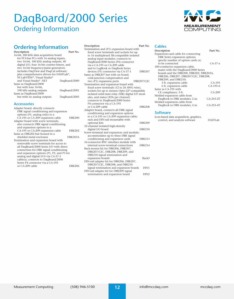
Ordering InformationDescription Part No.16-bit, 200 kHz data acquisition board
for PCI-bus PCs with 16 analog inputs, two 16-bit, 100 kHz analog outputs, 40 digital I/O, four 16-bit counter-timers, and two 16-bit frequency/pulse generators; includes DaqView and DaqCal software; plus comprehensive drivers for DASYLab®, NI LabVIEW®, Visual Studio® and Visual Studio® .NET DaqBoard/2000
Same as DaqBoard/2000 but with four 16-bit, 100 kHz analog outputs DaqBoard/2001
Same as DaqBoard/2000 but with no analog outputs DaqBoard/2005
Description Part No.Termination and (P1) expansion board with
fixed screw terminals and sockets for up to 16 multiplexed 5B-compatible isolated analog input modules; connects to DaqBoard/2000 Series (P4) connector via a CA-195 or CA-209 cable and to LogBook or DaqBook Series devices (P1) connector via CA-37-1 DBK207
Same as DBK207 but with on board, cold-junction compensation and two (P1) expansion ports DBK207/CJC
Termination and expansion board with fixed screw terminals (12 to 26 AWG wire), sockets for up to sixteen Opto-22®-compatible isolated solid-state-relay (SSR) digital I/O mod-ules, and status LEDs per channel; connects to DaqBoard/2000 Series P4 connector via a CA-195 or CA-209 cable DBK208
Adapter board, connects all DBK signal conditioning and expansion options to a CA-195 or CA-209 expansion cable; rack and DIN-rail mountable with optional kits DBK209
32-channel isolated high-density digital I/O board DBK210
Screw-terminal and expansion card module; accommodates up to three DBK signal conditioning and expansion cards DBK213
16-connector BNC interface module with internal screw-terminal connections DBK214
Rack-mount kit for DBK206, DBK207, DBK207/CJC, DBK208, DBK209, and DBK210 signal termination and expansion boards Rack3
DIN-rail adapter kit for DBK206, DBK207, DBK207/CJC, DBK208, and DBK210 signal termination and expansion boards DIN1
DIN-rail adapter kit for DBK209 signal termination and expansion board DIN2
CablesDescription Part No.Expansion-card cable for connecting
DBK Series expansion options; specify number of option cards (x) to be connected CA-37-x
100-conductor expansion cable, mates with the DaqBoard/2000 Series boards and the DBK200, DBK202, DBK203A, DBK206, DBK207, DBK207/CJC, DBK208, DBK209, and DBK210;
3 ft. expansion cable CA-195 6 ft. expansion cable CA-195-6Same as CA-195 with
CE compliance; 3 ft. CA-209Molded expansion cable from
DaqBook to DBK modules; 2 in. CA-255-2TMolded expansion cable from
DaqBook to DBK modules; 4 in. CA-255-4T
SoftwareIcon-based data acquisition, graphics,
control, and analysis software DASYLab
AccessoriesAdapter board, directly connects
DBK signal conditioning and expansion options (P1, analog only) to a CA-195 or CA-209 expansion cable DBK200
Adapter board with screw terminals, also connects DBK signal conditioning and expansion options to a CA-195 or CA-209 expansion cable DBK202
Same as DBK202 but housed in a shielded metal enclosure DBK203A
Termination and expansion board with removable screw terminals for access to all DaqBoard/2000 Series I/O with direct connection for DBK signal conditioning and expansion options (P1, P2, and P3 for analog and digital I/O) via CA-37-1 cable(s); connects to DaqBoard/2000 Series P4 connector via a CA-195 or CA-209 cable DBK206