16. APTA PR-M-S-016-06 Standard for Safety … PR-M-S-016-06 Standard for Safety Appliances for Rail...
46
APTA PR-M-S-016-06 16. APTA PR-M-S-016-06 Standard for Safety Appliances for Rail Passenger Cars Approved May 18, 2007 APTA PRESS Task Force Authorized June 2, 2007 APTA Commuter Rail Executive Committee Abstract: This standard establishes requirements for safety appliance design, installation and maintenance for rail passenger cars. Key Words: safety appliance, handbrake, sill step, side door step, sill step handhold, side door handhold, crew handhold, end handhold, collision post handhold, roof handhold, ladder, uncoupling device, attachment, handrail Copyright © 2007 by The American Public Transportation Association 1666 K Street, N. W. Washington, DC, 20006, USA No part of this publication may be reproduced in any form, in an electronic retrieval system or otherwise, without the prior written permission of The American Public Transportation Association. 16.1 Volume V- Mechanical
Transcript of 16. APTA PR-M-S-016-06 Standard for Safety … PR-M-S-016-06 Standard for Safety Appliances for Rail...

APTA PR-M-S-016-06
16. APTA PR-M-S-016-06 Standard for Safety Appliances
for Rail Passenger Cars
Approved May 18, 2007 APTA PRESS Task Force
Authorized June 2, 2007
APTA Commuter Rail Executive Committee
Abstract: This standard establishes requirements for safety appliance design, installation and maintenance for rail passenger cars.
Key Words: safety appliance, handbrake, sill step, side door step, sill step handhold, side door handhold, crew handhold, end handhold, collision post handhold, roof handhold, ladder, uncoupling device, attachment, handrail
Copyright © 2007 by The American Public Transportation Association
1666 K Street, N. W. Washington, DC, 20006, USA
No part of this publication may be reproduced in any form, in an electronic retrieval
system or otherwise, without the prior written permission of The American Public Transportation Association.
16.1 Volume V- Mechanical

APTA PR-M-S-016-06
Introduction
(This introduction is not part of the standard)
The American Public Transportation Association (APTA) undertook the development of this standard because the application of the Federal regulations contained in 49 CFR Part 231 governing safety appliances to modern passenger equipment has become difficult. 49 CFR 231 contains three different passenger car types in parts 231.12 (Passenger-train cars with wide vestibules), 231.13 (Passenger-train cars with open-end platforms) and 231.14 (Passenger-train cars with without end platforms). Modern equipment designs do not follow these specific car configurations. The passenger railroads have introduced multiple level cars, cars with center boarding, cab cars, etc. These new car types do not easily fit into the three types defined in the regulation. As a result, almost one-third of the passenger equipment in operation today contains one or more safety appliance features that are not in compliance with the way the Federal Railroad Administration interprets the requirements of 49 CFR Part 231.
APTA developed this standard to provide clarity in the design, fabrication and installation of safety appliances for modern designs of passenger cars. The standard clearly defines the function of each type of safety appliance and gives detailed requirements on the dimensions, material, location and manner of attachment. An annex of the standard includes a compliance check list that car builders can use as a quality control tool to ensure compliance with the standard.
APTA developed this standard using a consensus (defined as a 75% majority) process that included representatives of all the parties affected. APTA patterned the standard after the Association of American Railroads’ (AAR) Standard AAR S-2044 covering freight car safety appliances. The AAR has petitioned FRA to incorporate the freight car safety appliance standard into the Federal regulations.
APTA intends similarly to petition the Federal Railroad Administration (FRA) and Transport Canada to incorporate this standard into the Federal regulations. APTA intends to approach the FRA to make sample car inspections of each new design of passenger car mandatory and to use the compliance check list contained in this standard as part of the basis for this sample car inspection. In the future, APTA believes these steps will greatly reduce the number of newly built passenger cars that do not comply with Federal safety appliance regulations.
The APTA working group that developed this safety appliance standard for passenger rail cars included an ergonomics professional. The ergonomics professional advised APTA that riding a sill step when holding on to a single handhold is difficult in some operating circumstances. As a result, the standard requires two handholds placed an ergonomically acceptable distance apart above each sill step on new cars.
This caused controversy because many car designs have doors near the corner of the car that would preclude the placement of the second handhold an ergonomically acceptable distance from the first handhold.
16.2 Volume V- Mechanical

APTA PR-M-S-016-06
Some passenger railroads currently prohibit their employees from riding sill steps because they believe the employees are safer riding inside the car or walking beside the car during switching moves. APTA surveyed 18 passenger railroads; 16 of them either currently have operating rules that prohibit riding sill steps or strongly discourage riding sill steps and would be willing to implement such an operating practice.
As a result of this survey, APTA considered an option to eliminate sill steps if the railroad has in place an operating practice that prohibits their use. The best way to enforce this operating practice is to eliminate the sill step. Employees cannot use what is not there. This solves the door-near-the-corner-of-the-car design problem. If a railroad wishes to operate equipment of this design, that railroad must either ban riding the sill step or determine a way to install a second handhold above the sill step an ergonomically correct distance from the first handhold.
Neither the FRA, Transport Canada nor the rail labor representatives to the working group supported this APTA proposal to make sill steps an option on future passenger cars. As a result of this lack of support, APTA modified the proposal. The standard now requires a sill step and two corresponding handholds an ergonomically correct distance apart for all new equipment. If a railroad wishes to procure new equipment designs where placement of two handholds above the sill step is not possible, that railroad may do so if it adopts an operating practice that prohibits riding that sill step. This new requirement accomplishes two important things: 1) for new equipment, railroad employees are provided the extra safety of a second handhold, or they are not allowed to expose themselves to the danger of riding a sill step equipped with only one handhold; and 2) railroads can continue to purchase equipment designs with corner doors. As with all compromises, the new requirement has a downside. A sill step with a single handhold must be provided even when the railroad bans riding the sill step. From a railroad’s perspective, this does not make sense. But it gained the FRA, Transport Canada and labor support necessary for APTA to go forward. This compromise answers labor’s concern over the interchange of equipment without sill steps between passenger railroads and overhauling such passenger cars in freight trains. Overall safety of railroad employees will increase with time as more cars with two handholds above sill steps enter the fleet.
16.3 Volume V- Mechanical

APTA PR-M-S-016-06
Participants
The American Public Transportation Association greatly appreciates the contributions of the following individuals who provided the primary effort in the drafting of this Standard for Safety Appliances for Rail Passenger Cars.
Allen Bieber Stephen Bonina David Brooks Gordon Campbell David Carter Stephen Carullo Ghislain Champire George Chipko Richard Conway Joshua Coran Craig Daly Ralph Dolinger Gary Fairbanks
Lawrence Fleischer Andrew Frohn Paul Furman Randy Gnam James Guseman Tom Herrmann Christopher Holliday Paul Jamieson John Janiszewski Larry Kelterborn Jeff Kovacs Nancy Lessard Peter Lloyd
Ken Mannen James Michel Marvin Napier Ron Newman George Payne Carol Rose Patrick Sheeran Carlos Sosa Richard Stegner James Stoetzel Harold Weisinger Charles Whalen Gary Widell
At the time this standard was completed, the Passenger Rail Equipment Safety Standards (PRESS) Mechanical Committee included the following members:
Dave Carter, Chair Steven Abramopaulos M. Andriani Gordon Bachinsky Jack Barnas Ken Barnish Al Bieber George Binns Brad Black Rick Brilz Chris Brockhoff Dick Bruss Dave Brooks Mark Campbell Gary Carr John Casale Al Cheren George A. Chipko Steve Chrismer Roger Collen Richard Conway Steve Costanzo Jack Coughlin Tim Cumbie Erik Curtis Graham Curtis Richard Curtis
Steve Dedmon John M. Dermody Greg Dvorchak Ed Deitt Magdy El-Sibaie John Elkins Dave Elliott Owen Evans Gary Fairbanks Ronald L. Farrell Andrew F. Farilla Benoit Filion Chuck Florian Greg Gagarin John Goliber Jeff Gordon Thomas Grant Harry Haber Kevin Heidrich Francois Henri Ken Hesser Christopher Holliday Paul E. Jamieson James Jewell Richard Johnson Joe Kalousek
Joe Kahr Bob Kells Larry Kelterborn Kevin Kesler Paul Kezmarsky Peter Klauser Sunil Kondapalli John P. Konrad Susan Kristoff Rick Laue Nicolas Lessard Jason Lipscomb Cameron Lonsdale Ben Lue William Lydon Susan Madigan Dan Magnus Eric Magel Frank Maldari George Manessis Jean Major John Mardente James Martin Brian Marquis Keith McCarrick Don Minini
16.4 Volume V- Mechanical

APTA PR-M-S-016-06
Heiner Moehren Donald Morrissey Dak Murthy Larry Niemond Thomas O’Brien Frank Orioles George Payne Fernando Pascual Tom Peacock John Pearson, Jr. Jim Pilch Ian Pirie Richard Polley John Posterino Anand Prabhakaran Chuck Prehm John Punwani Russ Quimby James G. Rees Al Roman Carol Rose Tom Rowbottom Daniel Ruppert John Rutkowski
Tom Rusin Michele Salvatore Radovan Sarunac Fred Schaerr Hans-Dieter Schaller David Schanoes Peter Schumacher Bill Sears Rebecca Sidelinger Kevin Simms Tom Simpson Albert C. Song Carlos Sosa Rex Springston Mark Stewart Monique Stewart Philip M. Strong Chris Studcart Dick Swaney Bob Swearingen Ali Tajaddini KI. Takeshita Joe Talafous Clive Thornes
Richard Trail Mike Trosino Tom Tsai Bob Tuzik Richard Vadnal Arun Virginkar John Wagner David Warner Douglas Warner Charles Whalen Brian Whitten Gary Widell James Wilson Bruce Wigod Werner H. Wodtke Clifford Woodbury Bob Wright P. Yablonsky H. Yamamori Greg Yovich Allan Zarembski John Zolock Steve Zuiderveen
16.5 Volume V- Mechanical

APTA PR-M-S-016-06
Table of Contents
1. Overview........................................................................................................................................................7
1.1 Scope .......................................................................................................................................................7 1.2 Purpose ....................................................................................................................................................7
2. References......................................................................................................................................................7
2.1 References ...............................................................................................................................................7 2.2 Coordinate System and Units of Measurement .......................................................................................8
3. Definitions, Abbreviations, and Acronyms....................................................................................................9
3.1 Definitions ...............................................................................................................................................9 3.2 Abbreviations and Acronyms ................................................................................................................13
4. Safety Appliances ........................................................................................................................................13
4.1 General ..................................................................................................................................................13 4.2 Purpose ..................................................................................................................................................13 4.3 Materials and Processes.........................................................................................................................14 4.4 Manner of Application...........................................................................................................................14
5. Safety Appliance Arrangement – General ...................................................................................................15
5.1 Handbrake / Parking brake ....................................................................................................................15 5.2 Sill Steps ................................................................................................................................................17 5.3 Side Door Steps .....................................................................................................................................19 5.4 Sill Step Handholds ...............................................................................................................................22 5.5 Side Door Handholds.............................................................................................................................27 5.6 Crew Handholds at Passenger Steps Used in Lieu of Sill Steps............................................................29 5.7 End Handholds ......................................................................................................................................31 5.8 Collision Post Handholds ......................................................................................................................32 5.9 Handrail on Open Platform Cars ...........................................................................................................33 5.10 Uncoupling Devices ............................................................................................................................34 5.11 Elective Safety Appliances ..................................................................................................................35
6. Semi-permanently Coupled Cars .................................................................................................................37
7. Safety Appliance Design Verification Inspection........................................................................................37
8. Inspection, Maintenance, Repair and Replacement .....................................................................................38
8.1 Inspection ..............................................................................................................................................38 8.2 Maintenance...........................................................................................................................................38 8.3 Repair and Replacement........................................................................................................................38
Annex A (informative) Sample Car Inspection Checklist ...............................................................................40
16.6 Volume V- Mechanical

APTA PR-M-S-016-06 Edited 7-1-07
APTA PR-M-S-016-06 Standard for Safety Appliances for Rail Passenger Cars
1. Overview
1.1 Scope
This standard applies to new railroad passenger cars of all types, including baggage cars, with initial procurement contract awarded on or after January 1, 2008, for use on the general railroad system of the United States and Canada. This standard does not apply to non-passenger carrying locomotives.
In the event of discrepancy between the text of this standard and the illustrations, the text shall govern.
1.2 Purpose
The American Public Transportation Association (APTA) developed this standard to enhance the operational safety of new passenger cars by recognizing modern analytical techniques and manufacturing methods and to provide clarity and uniformity in the application of safety appliance regulations. APTA intends to petition the Federal Railroad Administration (FRA) and Transport Canada to incorporate this standard in total or by reference into the appropriate Rules and Regulations. If that happens, changes to existing contracts resulting in financial burdens caused by this standard should be handled through the established FRA and Transport Canada waiver/exemption processes.
2. References
2.1 References
This standard is to be used in conjunction with the following publications. When non-regulatory references are superseded by an approved revision, the revision shall apply for this standard and APTA will petition FRA and Transport Canada for a corresponding change in their rules and regulations.
49 CFR, Part 231, Railroad Safety Appliance Standards
49 CFR, Part 238, Rail Passenger Equipment Safety Standards
AAR S-2044, Requirements for Freight Car Safety Appliances
APTA SS-C&S-020-03, Standard for Passenger Rail Vehicle Structural Repair
APTA PR-IM-S-007-98, Rev. 1, Standard for Passenger Car Exterior Periodic Inspection and Maintenance
APTA PR-M-S-006-98, Rev. 1, Standard for Parking Brakes for New Passenger Locomotives and Cars
16.7 Volume V- Mechanical

APTA PR-M-S-016-06 Edited 7-1-07
AWS D1.1-06, Structural Welding Code – Steel
AWS D1.3-98, Structural Welding Code – Sheet Steel
AWS D1.6-99, Structural Welding Code – Stainless Steel
CSA W47.1-03, Certification of Companies for Fusion Welding of Steel
CSA W59-03, Welded Steel Construction (Metal Arc Welding)
Transport Canada’s Passenger Car Inspection and Safety Rules
2.2 Coordinate System and Units of Measurement
The following figures show the coordinate system used in this standard. This coordinate system is used to be consistent with FRA and Association of American Railroads (AAR) terminology. Figure 1 shows coordinates in relation to safety appliances. Figure 2 shows coordinates in relation to the passenger car.
Vertical dimensions defined relative to the top of rail are to be based on new, empty car conditions.
Units of measurement used in this Standard are United States (U.S.) customary units. These are followed by their arithmetic equivalents in International System (SI) units, enclosed in parentheses. The first value stated shall be regarded as the requirement. The converted equivalent value may be approximate.
Figure 1 – Safety Appliance Coordinate System
16.8 Volume V- Mechanical

APTA PR-M-S-016-06 Edited 7-1-07
Figure 2 – Passenger Car Coordinate System
3. Definitions, Abbreviations, and Acronyms
3.1 Definitions
3.1.1 clear depth: As applied to step treads, is the distance measured vertically from the top surface of the tread to the closest obstruction anywhere within the specified minimum clear width and useable length. See Figure 3.
3.1.2 clear length: As applied to handholds, is that distance about which a minimum 2 inch (51 mm) hand clearance (from obstructions due to car design) exists in all directions around the handhold. The clear length of one portion of a handhold does not include handhold portions in other directions or bend radii connecting non-continuous portions of a handhold. Intermediate supports may be considered part of the clear length. Unless otherwise stated, limitations on handhold length apply to the clear length. See Figure 4.
16.9 Volume V- Mechanical

APTA PR-M-S-016-06 Edited 7-1-07
Figure 3 – Sill Step Length and Clearances
Figure 4 – Clear Length of Handholds
16.10 Volume V- Mechanical

APTA PR-M-S-016-06 Edited 7-1-07
3.1.3 clear width: As applied to step treads, is the distance measured from the outboard surface of the tread to the closest inboard obstruction anywhere within the specified minimum clear depth and useable length. See Figure 3.
3.1.4 clearance points: As applied to handholds, are the ends of the clear length. See Figure 4.
3.1.5 collision post handhold: Handhold located at the end passageway of the vehicle to stabilize an employee when standing at the end of the car guiding reverse moves and to stabilize an employee when walking between cars.
3.1.6 crew handhold: Handhold used to assist an employee while entering or leaving a passenger entrance.
3.1.7 end handhold: Handhold located at the end of the vehicle to stabilize an employee when using the uncoupling device or as needed when connecting and disconnecting hoses and cables or when inspecting the vehicle.
3.1.8 fastener locking device: A device applied to a fastener to prevent the fastener from loosening.
3.1.9 handbrake: A brake that can be applied and released by hand to prevent movement of a rail car.
3.1.10 handrail: A rail serving as a support or guard on open platform cars to enclose the platform area and stabilize an employee standing on the open platform.
3.1.11 inboard: Towards the centerline of the car in either the transverse or longitudinal direction.
3.1.12 ladder: An arrangement of treads and/or handholds used for climbing to allow an employee to access equipment or perform a function that cannot be done from the ground.
3.1.13 longitudinal: Parallel to the centerline of track.
3.1.14 open platform car: A railcar with a non-enclosed section at the end of the car.
3.1.15 outboard: Away from the centerline of the car in either the transverse or longitudinal direction.
3.1.16 parking brake: A system that is applied to prevent a car from rolling due to gravity. This shall include systems referred to as handbrakes.
3.1.17 prevailing-off torque: The torque measured when the fastener is being removed when there is zero axial load in the assembly.
3.1.18 roof handhold: Handhold located on the roof to be gripped for support when performing maintenance or inspections on the roof.
16.11 Volume V- Mechanical

APTA PR-M-S-016-06 Edited 7-1-07
3.1.19 securely fastened: Applied with steel bolts or cap screws not less than 1/2 inch (M12) diameter. The bolts or cap screws shall conform to one of the following specifications:
• Carbon/low alloy steel – SAE J429, Grade 5 (English units) or SAE J1199, Grade 9.8 (metric units)
• Stainless steel – ASTM F593, Groups 1-3, Condition CW1 (English units) or ASTM F738M, Grades A1-70, A2-70 or A4-70, Condition CW (metric units)
Nuts of corresponding strength and appropriate chemical composition shall be used.
The fasteners must be secured by one of the following methods:
• When the nuts are facing out, the nuts may be riveted over or chisel checked to 1/8 inch depth at two locations.
• If nuts are not riveted over, or for all cases where the fastener is threaded inward, securely fastened appliances shall include locking devices conforming with one of the following criteria:
o Self locking nuts or lock washers.
o Wedge-locking washers consisting of two symmetrically designed washers that have inclined ramps on the sides in mutual contact and non-slip contact surfaces on the sides in contact with the nut and workpiece. Similar washer and nut arrangements utilizing the same locking principles are also acceptable.
o Other locking devices with minimum design prevailing-off torque (for the first removal) of 22 in.lb. (2.5 N-m).
Alternately, one-piece or two piece rivets or Huck bolts may be used.
All specialty or proprietary locking devices, rivets, or bolts shall be installed in accordance with the manufacturer's published instructions.
Fasteners used in securely fastened equipment shall not be re-used.
3.1.20 semi-permanently coupled: Coupled by means of a drawbar or other coupling mechanism that requires tools to perform the uncoupling operation. Coupling and uncoupling of each semi-permanently coupled unit in a train can be performed safely only while at a maintenance or shop location where employees can safely get under or between units.
3.1.21 side door handhold: Handhold located on the side of the car above a side door step.
3.1.22 side door step: Step or stirrup located on the side of the car to assist an employee in entering or leaving a side door entrance.
3.1.23 sill step: Step or stirrup located on the side, near the end of the car to allow an employee to ride on the side of the car during switching moves.
16.12 Volume V- Mechanical

APTA PR-M-S-016-06 Edited 7-1-07
3.1.24 sill step handhold: Handhold located on the side of the car above a sill step.
3.1.25 transverse: Perpendicular to the centerline of the track in the horizontal plane.
3.1.26 uncoupling device: Mechanism used to uncouple cars without requiring an employee to go between cars.
3.1.27 useable length: As applied to sill steps, side door steps and step treads, is the straight length, not including bend radii, above which the specified minimum clear depth exists. Unless otherwise stated, limitations on the length of sill steps and step treads apply to the useable length. See Figure 3.
3.2 Abbreviations and Acronyms
AAR Association of American Railroads ATR above top of rail AWS American Welding Society CFR Code of Federal Regulations CWB Canadian Welding Bureau FRA Federal Railroad Administration kg kilograms lb pounds mm millimeter MPa megapascal psi pounds per square inch SAE Society of Automotive Engineers SI International System of Units U.S. United States
4. Safety Appliances
4.1 General
Safety appliances applied to cars shall be designed, manufactured, installed and maintained in accordance with the requirements of this standard. Refer to the appropriate railroad’s clearance diagram when designing safety appliances and their locations.
Note: APTA recommends that railroads and carbuilders consider designing to dimensions greater than the minimums and less than the maximums contained in this standard to allow for manufacturing tolerances and other minor deviations.
4.2 Purpose
A safety appliance aids railroad employees or contractors in performing their duties safely by providing a means to support and/or stabilize themselves while riding equipment, entering or leaving equipment, inspecting equipment, coupling/uncoupling equipment or setting handbrakes.
16.13 Volume V- Mechanical

APTA PR-M-S-016-06 Edited 7-1-07
4.3 Materials and Processes
All sill steps, side door steps, ladders, handrails and handholds shall be made of steel with minimum yield strength of 25,000 psi (170 MPa). Stainless steel of equivalent strength may be used. Safety appliances may be cast, rolled, forged or made by any other process that provides the required strength.
To allow for standard mill tolerances, actual sizes of components (i.e. material thickness, diameter, etc.) may be 5% below the nominal sizes. Clearance dimensions are minimum dimensions (-0%).
4.4 Manner of Application
a) All safety appliances shall be securely fastened to the carbody structure.
b) Brackets or supports to which safety appliances are fastened are considered part of the carbody and are not required to be mechanically fastened to the piece of passenger equipment if all of the following are met:
1) Except for any access required for attachment of the safety appliance, the weld is continuous around the perimeter of the surface of the bracket or support;
2) The area of the weld is sufficient to ensure a minimum weld strength, based on yield, of three times the strength of the number of SAE Grade 2, 1/2 inch diameter (M12 Class 5.8) bolts that would be required for each attachment;
3) The attachment is made with fillet welds at least 3/16 inch (5 mm) in size;
4) The bracket or support is welded to a surface of the carbody that is at a minimum 3/16 inch (5 mm) sheet steel or is structurally reinforced to provide the equivalent strength and rigidity of 3/16 inch (5 mm) sheet steel;
5) The weld takes into account the variable stress state of the carbody at the weld location;
6) The weld is designed for infinite fatigue life in the application in which it will be placed;
7) The weld is performed in accordance with the welding process and the quality control procedures contained in the current American Welding Society (AWS) Standard, the Canadian Welding Bureau (CWB) Standard or an equivalent nationally or internationally recognized welding standard;
8) The weld is performed by an individual possessing the qualifications to be certified under the current AWS Standard, CWB Standard or any equivalent nationally or internationally recognized welding qualification standard;
9) The weld is inspected by an individual qualified to determine that all welds are in conformance with the design drawings and the current AWS Standard, CWB Standard or any equivalent nationally or internationally recognized welding qualification standard; and,
10) A written or electronic record of the inspection required in paragraph 9) of this section shall be preserved and shall be provided to the FRA or Transport Canada upon request. At a
16.14 Volume V- Mechanical

APTA PR-M-S-016-06 Edited 7-1-07
minimum, this record shall include date, time, location, identification of the person performing the inspection and the qualifications of the person performing the inspection.
5. Safety Appliance Arrangement – General
5.1 Handbrake / Parking brake
5.1.1 General
Except as provided in Section 6, each car shall have a handbrake or parking brake that complies with APTA PR-M-S-006-98, Rev. 1, and that operates in harmony with the power brake equipment on the car. If a parking brake is used, it shall be capable of being set from each car, and each car shall be equipped with a means to release the parking brake manually.
5.1.2 Purpose/Function
The handbrake/parking brake is used to apply force mechanically to one or more brake shoes or pads on the car.
5.1.3 Location (Figures 5 and 6)
5.1.3.1 General – Handbrakes, Lever or Wheel Type
a) The handbrake as installed, whether applied or released, and in its stored position shall be located so as to not restrict passenger flow through any passageway.
b) The handbrake shall be located so it can be safely operated while the car is in motion.
c) A handhold shall be provided to stabilize an employee when using the handbrake.
d) The center point of the wheel or the pivot point of the lever used to apply the handbrake shall be located 31 to 40 inches (787 to 1016 mm) above the floor.
5.1.3.2 Handbrake – Lever Type
a) Any handbrake handle retention mechanism shall not interfere with the normal grip position of the lever.
b) The handbrake lever and release lever shall have a minimum 2 inch (51 mm) hand clearance in the stored position. The handbrake lever shall have a minimum 24 inch (610 mm) body clearance on one side of the lever and a minimum 4 inch (102 mm) hand clearance on the opposite side and end in the operating position.
c) The clearance between the grip portion of the release lever, if used, and any part of the car shall be no less than 2.5 inches (64 mm).
16.15 Volume V- Mechanical

APTA PR-M-S-016-06 Edited 7-1-07
31”-40” Floor to
Pivot Point of Lever
Figure 5 - Lever Type Handbrake
5.1.3.3 Handbrake – Wheel Type
a) The wheel type handbrake shall have a minimum 4 inch (102 mm) hand clearance.
b) The wheel diameter shall be at least 22 inches (559 mm).
16.16 Volume V- Mechanical

APTA PR-M-S-016-06 Edited 7-1-07
Figure 6 – Wheel Type Handbrake
5.1.3.4 Parking Brake
The parking brake manual release lever shall have a minimum 2 inch (51 mm) hand clearance.
5.1.4 Manner of Application – Details
The handbrake housing must be securely fastened. Bolts used for mounting the handbrake shall be designed to resist the maximum chain force with a minimum factor of safety of 2. The maximum chain force is that developed by the handbrake mechanism when a 125 lb. (556 Newton) force is applied 3 inches (76 mm) in from the end of the application lever, typically 20 to 24 inches (508 to 610 mm) long, or on the rim of a handbrake wheel unless the design of the mechanism restricts the applied force to a lower value.
Hand brake mounting brackets are to be securely fastened unless the use of mechanical fasteners is not feasible for the particular application. Bell crank mounting brackets, sheave wheel mounting brackets, brake rod supports and guides, and chain supports and guides are not considered safety appliances, and hence are not subject to the manner of application requirements in this standard. See Figures 5 and 6 for typical handbrake applications.
5.2 Sill Steps
5.2.1 General
Except as provided in Section 6, each car shall have a sill step applied at each corner of the car where no useable passenger step is available.
16.17 Volume V- Mechanical

APTA PR-M-S-016-06 Edited 7-1-07
5.2.2 Purpose/Function
Sill steps allow an employee to ride on the side, near the end of the car during switching moves.
5.2.3 Dimensions
a) The minimum useable length of tread shall be not less than 12 inches (305 mm).
b) Sill steps shall be no less than 1/2 inch (13 mm) thick and no less than 2 inches (51 mm) wide. Alternate material sections may be used if they maintain the equivalent strength and rigidity of a 1/2 inch (13 mm) thick by 2 inch (51 mm) width step. Tread width shall be maintained at a 2 inch (51 mm) minimum.
c) The clear depth above the entire useable length of the sill step tread shall be no less than 8 inches (203 mm) and the clear width of all sill step treads shall be no less than 6 inches (152 mm) with the trucks rotated to simulate the maximum curvature specified for the uncoupled car.
d) To account for minor deviations, the application of sill steps shall be such that a box with the following dimensions can pass through the opening above the sill step to the point where the box is flush with the outer edge of the step. See Figure 3.
Box Length Box Depth Box Width
Sill step 10 inches (254 mm)
8 inches (203 mm)
6 inches (152 mm)
5.2.4 Location (Figures 7 and 9-13)
a) One sill step shall be applied at each corner of the car. A passenger step may be used in lieu of a sill step if it meets the clear depth, clear width, useable length and location requirements for a sill step.
b) The outboard end of the useable length of the sill step shall be not more than 18 inches (457 mm) in the longitudinal direction from the corner of the car. For cars without well-defined corners, the intent is for the sill step to be positioned for the employee to have an unobstructed view of the track ahead. The sill step shall be placed so the employee has a clear view in both longitudinal directions and shall be placed outside of the gauge of the track.
c) Steps exceeding 18 inches (457 mm) in depth shall be transversely braced or equivalent.
d) The design goal is to have the tread of the sill step as close to the top of rail as the clearance diagram permits. The sill step tread shall be not more than 24 inches (610 mm), preferably not more than 22 inches (560 mm), above the top of rail.
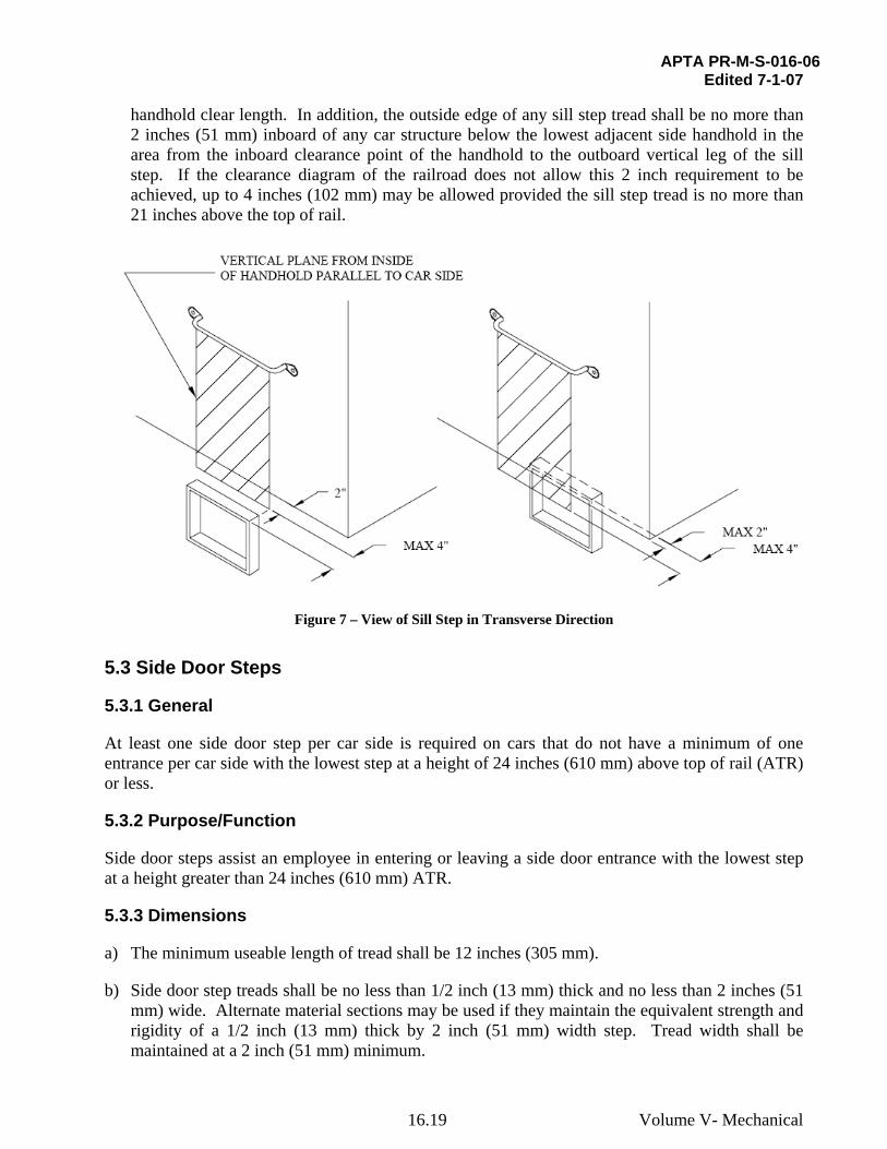
e) The design goal is to have the outside edge of the tread of the sill step as close to being flush with the side of the car as the clearance diagram permits. To align sill step width with respect to handholds, in the transverse direction, the outside edge of any sill step tread shall not be more than 4 inches (102 mm) inboard or outboard of the inside surface of the lowest adjacent side
16.18 Volume V- Mechanical
APTA PR-M-S-016-06 Edited 7-1-07
handhold clear length. In addition, the outside edge of any sill step tread shall be no more than 2 inches (51 mm) inboard of any car structure below the lowest adjacent side handhold in the area from the inboard clearance point of the handhold to the outboard vertical leg of the sill step. If the clearance diagram of the railroad does not allow this 2 inch requirement to be achieved, up to 4 inches (102 mm) may be allowed provided the sill step tread is no more than 21 inches above the top of rail.
Figure 7 – View of Sill Step in Transverse Direction
5.3 Side Door Steps
5.3.1 General
At least one side door step per car side is required on cars that do not have a minimum of one entrance per car side with the lowest step at a height of 24 inches (610 mm) above top of rail (ATR) or less.
5.3.2 Purpose/Function
Side door steps assist an employee in entering or leaving a side door entrance with the lowest step at a height greater than 24 inches (610 mm) ATR.
5.3.3 Dimensions
a) The minimum useable length of tread shall be 12 inches (305 mm).
b) Side door step treads shall be no less than 1/2 inch (13 mm) thick and no less than 2 inches (51 mm) wide. Alternate material sections may be used if they maintain the equivalent strength and rigidity of a 1/2 inch (13 mm) thick by 2 inch (51 mm) width step. Tread width shall be maintained at a 2 inch (51 mm) minimum.
16.19 Volume V- Mechanical

APTA PR-M-S-016-06 Edited 7-1-07
c) Steps exceeding 18 inches (457 mm) in depth shall have an additional tread and be transversely braced or equivalent.
d) The clear depth above the entire useable length of the lowest side door step tread shall be no less than 8 inches (203 mm) and the clear depth above the entire useable length of all other side door step treads shall be no less than 6 inches (152 mm). The clear width of all side door step treads shall be no less than 6 inches (152 mm) with the trucks rotated to simulate the maximum curvature specified for the uncoupled car.
e) To account for minor deviations, the application of side door steps shall be such that a box with the following dimensions can pass through the opening above the side door step to the point where the box is flush with the outer edge of the step. See Figure 3.
Box Length Box Depth Box Width
Lowest side door step 10 inches (254 mm)
8 inches (203 mm)
6 inches (152 mm)
All side door steps, except lowest
10 inches (254 mm)
6 inches (152 mm)
6 inches (152 mm)
5.3.4 Location (Figure 8)
a) For side door steps that extend beyond the side door opening in the longitudinal direction, the inside face of the leg of the side door step that is located under the door opening shall be at least 10 inches (254 mm) in the longitudinal direction from the vertical inside face of the door opening. The inside face of the opposite leg of the side door step shall be located on the centerline of the side door handhold or extend beyond it.
16.20 Volume V- Mechanical

APTA PR-M-S-016-06 Edited 7-1-07
Figure 8 - Side Door Steps and Vertical Handholds at Non-End of Car with High-Level Entrance
b) The design goal is to have the tread of the side door step as close to the top of rail as the clearance diagram permits. The lowest tread shall be not more than 24 inches (610 mm), preferably not more than 22 inches (560 mm), above the top of rail.
c) The design goal is to have the outside edge of the tread of the side door step as close to being flush with the side of the car as the clearance diagram permits. To align side door step width with respect to handholds, in the transverse direction, the outside edge of any step tread shall not be more than 6 inches (152 mm) inboard or outboard of the inside surface of the lowest adjacent side handhold clear length. In addition, the outside edge of any step tread shall be no more than 2 inches (51 mm) inboard of any car structure below the lowest adjacent side handhold in the area from the inboard clearance point of the handhold to the outboard vertical leg of the step. If the clearance diagram of the railroad does not allow this 2 inch requirement to be achieved, up to 4 inches (102 mm) may be allowed provided the lowest tread is no more than
16.21 Volume V- Mechanical
APTA PR-M-S-016-06 Edited 7-1-07
21 inches above the top of rail. See Figure 7.
5.4 Sill Step Handholds
5.4.1 General
Except as provided in Section 6, sill step handholds shall be applied over each sill step.
5.4.2 Purpose/Function
Sill step handholds are used to stabilize an employee while riding on the sill step.
5.4.3 Dimensions
Handholds shall be no less than 5/8 inch (16 mm) diameter. Minimum clear length of handholds shall be 16 inches (406 mm). Minimum clearance shall be 2 inches (51 mm), preferably 2.5 inches (64 mm).
5.4.4 Location (Figures 9-13)
a) There shall be a minimum of two handholds over each sill step. If it is not possible to place two handholds over a sill step, there shall be one handhold over that sill step and the railroad shall prohibit employees from riding on that sill step.
Note: When only one sill step handhold is used, APTA recommends that a “DO NOT RIDE” sign be affixed to the car above the sill step.
b) When at least two horizontal handholds are used, one horizontal handhold shall be at most 54 inches (1372 mm) ATR. The second horizontal handhold shall be 54 to 58 inches (1372 to 1473 mm) above the step. See Figure 9.
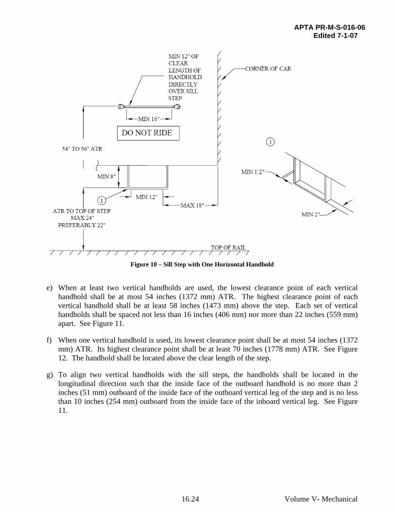
c) When one horizontal handhold is used, it shall be 54 to 56 inches (1372 to 1423 mm) ATR. See Figure 10.
d) Twelve inches (305 mm) of the clear length of each horizontal handhold shall be directly over the sill step. See Figure 9.
16.22 Volume V- Mechanical

APTA PR-M-S-016-06 Edited 7-1-07
Figure 9 – Sill Step with Two Horizontal Handholds
16.23 Volume V- Mechanical
APTA PR-M-S-016-06 Edited 7-1-07
Figure 10 – Sill Step with One Horizontal Handhold
e) When at least two vertical handholds are used, the lowest clearance point of each vertical handhold shall be at most 54 inches (1372 mm) ATR. The highest clearance point of each vertical handhold shall be at least 58 inches (1473 mm) above the step. Each set of vertical handholds shall be spaced not less than 16 inches (406 mm) nor more than 22 inches (559 mm) apart. See Figure 11.
f) When one vertical handhold is used, its lowest clearance point shall be at most 54 inches (1372 mm) ATR. Its highest clearance point shall be at least 70 inches (1778 mm) ATR. See Figure 12. The handhold shall be located above the clear length of the step.
g) To align two vertical handholds with the sill steps, the handholds shall be located in the longitudinal direction such that the inside face of the outboard handhold is no more than 2 inches (51 mm) outboard of the inside face of the outboard vertical leg of the step and is no less than 10 inches (254 mm) outboard from the inside face of the inboard vertical leg. See Figure 11.
16.24 Volume V- Mechanical

APTA PR-M-S-016-06 Edited 7-1-07
Figure 11 – Sill Step with Two Vertical Handholds
16.25 Volume V- Mechanical

APTA PR-M-S-016-06 Edited 7-1-07
Figure 12 – Sill Step with One Vertical Handhold
h) When a combination of horizontal and vertical handholds is used, the horizontal handhold shall be 54 to 58 inches (1372 to 1473 mm) above the step. The lowest clearance point of the vertical handhold shall be at most 54 inches (1372 mm) ATR. The highest clearance point of the vertical handhold shall be at least 70 inches (1778 mm) ATR. See Figure 13. One continuous handhold may be used as long as it meets the dimensional requirements of this paragraph.
16.26 Volume V- Mechanical

APTA SS-M-016-06 Edited 7-1-07
Figure 13 – Sill Step with One Horizontal and One Vertical Handhold
5.5 Side Door Handholds
5.5.1 General
Except as provided in Section 6, a side door handhold shall be applied over each side door step.
5.5.2 Purpose/Function
Side door handholds are used to assist an employee while entering or leaving a car.
5.5.3 Dimensions
Handholds shall be no less than 5/8 inch (16 mm) diameter. Minimum clear length of vertical handholds shall be 24 inches (610 mm). Minimum clearance shall be 2 inches (51 mm), preferably 2.5 inches (64 mm).
16.27 Volume V- Mechanical

APTA PR-M-S-016-06 Edited 7-1-07
5.5.4 Location (Figures 14 and 15)
a) There shall be one vertical side door handhold over each side door step.
b) The lowest clearance point of the side door handhold shall be at most 54 inches (1372 mm) ATR.
c) If the side door handhold is located outside of the side door opening, the side door handhold shall be located no more than 6 inches (152 mm) from the vertical inside face of the door opening.
d) On cab cars with non-passenger side entrances, two vertical side door handholds shall be installed, one on each side of the door, to continue to a point at least 58 inches (1473 mm) above the cab floor at the door entrance. If the length of the handhold exceeds 60 inches (1524 mm), it shall be securely fastened with two fasteners at each end.
Figure 14 – Side Door Step with Vertical Handhold
16.28 Volume V- Mechanical

APTA PR-M-S-016-06 Edited 7-1-07
Figure 15 – Side Door Step with Vertical Handhold at End of Car
5.6 Crew Handholds at Passenger Steps Used in Lieu of Sill Steps
5.6.1 General
Except as provided in Section 6, on cars with passenger entrances with the lowest step at a height of 24 inches ATR or less, crew handholds shall be applied above at least one passenger entrance per car side.
5.6.2 Purpose/Function
Crew handholds are used to assist an employee while entering or leaving a car at passenger entrances 24 inches ATR or less.
16.29 Volume V- Mechanical

APTA PR-M-S-016-06 Edited 7-1-07
5.6.3 Dimensions
Handholds shall be no less than 5/8 inch (16 mm) diameter. Minimum clear length of vertical handholds shall be 33 inches (838 mm). Minimum clearance shall be 2 inches (51 mm), preferably 2.5 inches (64 mm).
5.6.4 Location (Figure 16)
a) There shall be two vertical crew handholds, one on each side of the door opening.
b) The lowest clearance point of each crew handhold shall be at most 54 inches (1372 mm) ATR.
c) If the crew handhold is located outside of the door opening, the crew handhold shall be located no more than 6 inches from the vertical inside face of the door opening.
Figure 16 – Crew Handholds at Passenger Steps
16.30 Volume V- Mechanical
APTA PR-M-S-016-06 Edited 7-1-07
5.7 End Handholds
5.7.1 General
Except as provided in Section 6, two end handholds shall be on each end of the car.
5.7.2 Purpose/Function
End handholds are used to stabilize an employee when performing such tasks as making or breaking end connections, opening and closing angle cocks and performing inspections.
5.7.3 Dimensions
Handholds shall be no less than 5/8 inch (16 mm) diameter. Minimum clear length of end handholds shall be 16 inches (406 mm). Minimum clearance shall be 2 inches (51 mm), preferably 2.5 inches (64 mm), with end connections applied and end receptacle covers in resting position.
5.7.4 Location (Figure 17)
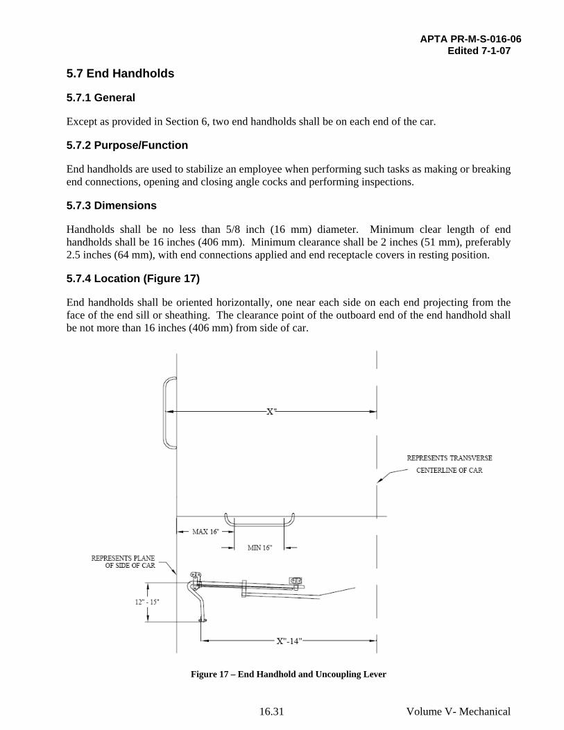
End handholds shall be oriented horizontally, one near each side on each end projecting from the face of the end sill or sheathing. The clearance point of the outboard end of the end handhold shall be not more than 16 inches (406 mm) from side of car.
Figure 17 – End Handhold and Uncoupling Lever
16.31 Volume V- Mechanical

APTA PR-M-S-016-06 Edited 7-1-07
5.8 Collision Post Handholds
5.8.1 General
Two collision post handholds shall be at each end passageway.
5.8.2 Purpose/Function
Collision post handholds provide a means to stabilize an employee standing at the end of the car guiding reverse moves. Collision post handholds also provide a means to stabilize an employee when walking between cars.
5.8.3 Dimensions
Handholds shall be no less than 5/8 inch (16 mm) diameter. Minimum clearance shall be 2 inches (51 mm), preferably 2.5 inches (64 mm).
5.8.4 Location (Figure 18)
Collision post handholds shall be oriented vertically. The lowest clearance point shall be at most 44 inches (1118 mm) above the floor of the walkway, and the highest clearance point shall be at least 60 inches (1524 mm) above the floor of the walkway.
Figure 18 – Collision Post Handholds
16.32 Volume V- Mechanical

APTA PR-M-S-016-06 Edited 7-1-07
5.9 Handrail on Open Platform Cars
5.9.1 General
Open platform cars shall have the platform area enclosed with either a handrail or shortened walls.
5.9.2 Purpose/Function
A handrail or a shortened wall is used on open platform cars to enclose the platform area and stabilize an employee standing on the open platform.
5.9.3 Dimensions
Handrails shall be no less than 1 inch (25.5 mm) diameter tubing with a minimum wall thickness of 1/16 inch (1.6 mm).
5.9.4 Location (Figure 19)
a) Open platform cars shall have the platform area enclosed with either a handrail or shortened walls. The handrail may be continuous or may be intermittent to extend between other members of the car such as collision posts and corner posts.
b) If an intermittent handrail is used, the end of the handrail shall be capped with a rounded end to reduce risk of injury.
c) The distance from the end of the handrail to a vertical car member shall not exceed 4 inches (102 mm).
d) The handrail shall be at least 42 inches (1071 mm) from the top of the platform floor to the top of the handrail, including entry doors.
e) The handrail arrangement shall be designed such that a 5 inch (127.5 mm) diameter ball cannot pass through any space between handrail members or between the handrail and the carbody.
f) Handrail members shall not be unsupported for spans over 48 inches (1224 mm).
g) The railing and stile assembly may be welded but the ends of the final assembly must be securely fastened to the car structure.
h) If a shortened wall is used, it shall meet the location requirement for handrails as detailed in items a) through g) above.
16.33 Volume V- Mechanical

APTA PR-M-S-016-06 Edited 7-1-07
Figure 19 – Handrail on Open Platform Car
5.10 Uncoupling Devices
5.10.1 General
Except as provided in Section 6, each car shall have either a mechanical uncoupling device at each end of the car or an uncoupling mechanism operated by controls located in a secure location in the car.
5.10.2 Purpose/Function
The uncoupling device is a mechanism used to uncouple cars without requiring an employee to go between cars.
5.10.3 Dimensions
If the uncoupling device is mechanically operated from the side of the car, the following shall
16.34 Volume V- Mechanical
APTA PR-M-S-016-06 Edited 7-1-07
apply:
a) Under all operating conditions, the outside surface of the uncoupling device handles shall be no more than 14 inches (356 mm) closer to the car center than the inside surface of the adjacent side handhold. See Figure 17.
b) Uncoupling attachments shall be applied so they can be operated by a person standing on the ground.
c) The bottom end of the handle shall be no less than 12 inches (305 mm) and no more than 15 inches (381 mm) below the centerline of the outermost pivot point of the uncoupling lever to which the handle is attached.
d) The end of handle shall be constructed to provide a minimum 2 inches (51 mm) clearance around the handle.
5.10.4 Location (Figure 17)
When used, the uncoupling levers shall be so applied that the coupler can be operated from the left side of the car as seen when facing the end of the car from the ground.
5.10.5 Manner of Application
The uncoupling lever device shall be securely fastened to the carbody structure or supporting bracket.
5.11 Elective Safety Appliances
Safety appliances applied to the exterior of cars in addition to those required by this standard are defined as “Elective Safety Appliances” and shall comply with the requirements of this standard that are applicable to similar safety appliances, except for their quantity and location.
5.11.1 General
When marker sockets or brackets are located so that they cannot be conveniently reached from platforms, suitable steps and handholds shall be provided for employees to reach such sockets or brackets. These steps and handholds shall follow the requirements for side door steps and side door handholds respectively. Alternately, the requirements for ladders may be used.
5.11.2 Ladders
5.11.2.1 Purpose/Function
Ladders are not required and are elective safety appliances. Ladders enable an employee to access equipment or to perform a function that cannot be done from the ground.
5.11.2.2 Dimensions
a) The minimum useable length of tread shall be not less than 16 inches (406 mm) on side ladders and not less than 14 inches (356 mm) on end ladders.
16.35 Volume V- Mechanical

APTA PR-M-S-016-06 Edited 7-1-07
b) Treads of rectangular cross-section shall be no less than 1/2 inch (13 mm) thick and no less than 2 inches (51 mm) wide. The minimum diameter of treads of circular cross-section shall be 5/8 inch (16 mm).
c) Minimum clearance of treads shall be 2 inches (51 mm), preferably 2.5 inches (64 mm).
d) All ladder treads shall have foot guards. Ladder side rails may serve as foot guards (Figure 20).
Figure 20 – Foot Guards on Ladder Treads
5.11.2.3 Location
a) If the ladder is used for access to the roof, the top ladder tread shall be no less than 12 inches (305 mm), nor more than 18 inches (457 mm), below the mounting surface of the outboard end of the adjacent roof handhold.
b) The maximum spacing between ladder treads shall be 19 inches (483 mm). Spacing of ladder
16.36 Volume V- Mechanical

APTA PR-M-S-016-06 Edited 7-1-07
treads shall be uniform within a limit of 2 inches (51 mm) from top ladder tread to bottom tread of ladder.
5.11.3 Roof Handholds
5.11.3.1 Purpose/Function
Roof handholds are not required and are elective safety appliances. Roof handholds are used on the roof of the car to stabilize an employee when performing such tasks as inspecting equipment located on the roof.
5.11.3.2 Dimensions
Handholds shall be no less than 5/8 inch (16 mm) diameter. Minimum clear length shall be 16 inches (406 mm). Minimum clearance shall be 2 inches (51 mm), preferably 2.5 inches (64 mm).
5.11.3.3 Location
If roof handholds are located above a ladder, in the transverse direction, the clearance points of the inboard end of roof handholds (bulkhead top handholds) shall be no more than 8 inches (203 mm) inboard from and no further outboard than the clearance point of the inboard end of the top ladder tread.
6. Semi-permanently Coupled Cars
Semi-permanently coupled cars need not be equipped with uncoupling levers, sill steps or end or side handholds at the articulated or drawbar connections between adjacent carbodies. However, when elective safety appliances are applied at such locations, they shall comply with the requirements of paragraph 5.10 of this standard.
Semi-permanently coupled cars shall be equipped with sufficient handbrakes/parking brakes to meet the grade holding capacity defined in APTA PR-M-S-006-98, Rev. 1.
7. Safety Appliance Design Verification Inspection
The railroad and the carbuilder may use the checklist in Annex A to verify that all the requirements of this standard have been addressed.
The carbuilder or railroad shall request a safety appliance sample car inspection from the FRA in the United States or Transport Canada in Canada on each new design of car. If any design changes take place to safety appliances during production, the carbuilder or railroad shall request an additional safety appliance sample car inspection.
Previous sample car inspections can be applied to new orders of the same design if there are no changes to the safety appliances. However, FRA and Transport Canada will require submittal of the safety appliance arrangement drawings for that order with reference to the previous sample car inspection.
This inspection can be combined with the standard sample car inspection. Both FRA and Transport Canada require inspection of items in addition to safety appliances during the sample car inspection.
16.37 Volume V- Mechanical

APTA PR-M-S-016-06 Edited 7-1-07
Contact FRA and/or Transport Canada for details on these requirements.
It is recommended that a safety appliance design review with the FRA or Transport Canada be conducted as early as possible in the design process. The carbuilder or railroad shall submit a written request to FRA and/or Transport Canada at least 30 days prior to a sample car inspection. The letter shall include the drawings of all safety appliances and may include the completed checklist in Annex A. The letter shall be sent to: Federal Railroad Administration:
Transport Canada:
Director, Office of Safety Assurance and Compliance Federal Railroad Administration U.S. Department of Transportation 400 7th Street, SW Mail Stop 25 Washington, DC 20590
Transport Canada Rail Safety Enterprise Building 427 Laurier Avenue West 14th floor Suite 1410 Ottawa, Ontario Canada, K1A 0N5
8. Inspection, Maintenance, Repair and Replacement
8.1 Inspection
Safety appliances shall be inspected in accordance with 49 CFR 238.303, APTA PR-IM-S-007-98, Rev. 1, and Transport Canada’s Railway Passenger Car Inspection and Safety Rules. Safety appliances shall be part of the periodic inspection of the car in accordance with 49 CFR 238.307, APTA PR-IM-S-007-98, Rev. 1, and Transport Canada’s Railway Passenger Car Inspection and Safety Rules. 8.2 Maintenance
Any safety appliance defects uncovered in the inspections required in Section 8.1 shall be repaired in accordance with 49 CFR 238.303; 49 CFR 238.307; APTA PR-IM-S-007-98, Rev. 1; and Transport Canada’s Railway Passenger Car Inspection and Safety Rules.
8.3 Repair and Replacement
When damaged safety appliances and/or their brackets or supporting structure are repaired or replaced, they shall be restored to their original design. See also APTA PR-CS-S-020-03, Standard for Passenger Rail Vehicle Structural Repair.
Fastener locking devices shall not be reused.
16.38 Volume V- Mechanical

APTA PR-M-S-016-06 Edited 7-1-07
Bibliography
[B1] AAR Manual of Standards and Recommended Practices, Section B, S-132, Type No. 6 Operating Mechanism
[B2] AAR Manual of Standards and Recommended Practices, Section C, S-224, Handhold and Ladder Tread Material and Design Specifications
[B3] AAR Manual of Standards and Recommended Practices, Section C, S-2042, Sill Step Performance Specification
[B4] AAR Manual of Standards and Recommended Practices, Section E, S-475, Geared Hand Brakes
[B5] FRA Motive Power and Equipment Compliance Manual, Chapter 2, Inspection and Compliance Program
[B6] SAE J429, 1999, Mechanical and Material Requirements for Externally Threaded Fasteners
16.39 Volume V- Mechanical

APTA PR-M-S-016-06 Edited 7-1-07
Annex A (informative) Sample Car Inspection Checklist
Safety Appliance Design Review Checklist Edited: 2-9-07
American Public Transportation Association
Reviewer: Organization: Date: Region:
Builder: Car Initials & Series: Car Type: Cars to be Built: Builder Job #
Item # Number - Dimensions - Location - Manner of ApplicationAPTA PR-M-S-
016-06 Reference
Notes
1. Each car has a handbrake or parking brake.
2. If parking brake is used, can be set from each car and can be released manually. 5.1.1
3. Located so as to not restrict passenger flow through any passageway, whether applied or released and in its stored position.
4. Located so it can be safely operated while the car is in motion.
5. A handhold is provided to stabilize an employee when using the handbrake.
6. Center point of the wheel or the pivot point of the lever is located 31 to 40 inches above floor.
5.1.3.1
7. Handbrake Housing and mounting brackets are securely fastened. 5.1.4
Lever Type Handbrake Only:
8. Handle retention mechanism does not interfere with the normal grip position of the lever.
9. In stored position, handbrake lever and release lever have a minimum 2 inch hand
clearance.
10. In operating position, lever has a minimum 24 inch body clearance on one side of the
lever and a minimum 4 inch hand clearance on the opposite side.
11. Clearance between the grip portion of the release lever, if used, and any part of the
car is no less than 2.5 inches.
5.1.3.2
Wheel Type Handbrake Only:
Handbrake / Parking Brake
12. The wheel type handbrake has a minimum 4 inch hand clearance.
5.1.3.3
16.40 Volume V- Mechanical
APTA PR-M-S-016-06 Edited 7-1-07
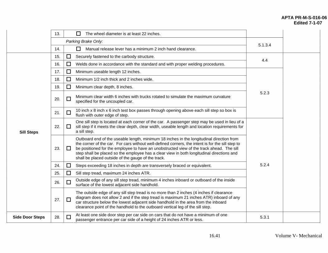
13. The wheel diameter is at least 22 inches.
Parking Brake Only:
14. Manual release lever has a minimum 2 inch hand clearance. 5.1.3.4
15. Securely fastened to the carbody structure.
16. Welds done in accordance with the standard and with proper welding procedures. 4.4
17. Minimum useable length 12 inches.
18. Minimum 1/2 inch thick and 2 inches wide.
19. Minimum clear depth, 8 inches.
20. Minimum clear width 6 inches with trucks rotated to simulate the maximum curvature specified for the uncoupled car.
21. 10 inch x 8 inch x 6 inch test box passes through opening above each sill step so box is flush with outer edge of step.
5.2.3
22. One sill step is located at each corner of the car. A passenger step may be used in lieu of a sill step if it meets the clear depth, clear width, useable length and location requirements for a sill step.
23.
Outboard end of the useable length, minimum 18 inches in the longitudinal direction from the corner of the car. For cars without well-defined corners, the intent is for the sill step to be positioned for the employee to have an unobstructed view of the track ahead. The sill step shall be placed so the employee has a clear view in both longitudinal directions and shall be placed outside of the gauge of the track.
24. Steps exceeding 18 inches in depth are transversely braced or equivalent.
25. Sill step tread, maximum 24 inches ATR.
26. Outside edge of any sill step tread, minimum 4 inches inboard or outboard of the inside surface of the lowest adjacent side handhold.
Sill Steps
27. The outside edge of any sill step tread is no more than 2 inches (4 inches if clearance diagram does not allow 2 and if the step tread is maximum 21 inches ATR) inboard of any car structure below the lowest adjacent side handhold in the area from the inboard clearance point of the handhold to the outboard vertical leg of the sill step.
5.2.4
Side Door Steps 28. At least one side door step per car side on cars that do not have a minimum of one passenger entrance per car side of a height of 24 inches ATR or less. 5.3.1
16.41 Volume V- Mechanical

APTA PR-M-S-016-06 Edited 7-1-07
29. Securely fastened to the carbody structure.
30. Welds done in accordance with the standard and with proper welding procedures. 4.4
31. Minimum useable length, 12 inches.
32. Minimum 1/2 inch thick and 2 inches wide. If alternate material sections are used, they maintain the equivalent strength and rigidity of a 1/2 inch thick and 2 inches wide step. Tread width is 2 inch minimum.
33. Steps exceeding 18 inches in depth have an additional tread and are transversely braced or equivalent.
34. Minimum clear depth of lowest side door step, 8 inches.
35. Minimum clear depth of all side door steps except lowest, 6 inches.
36. Minimum clear width 6 inches with trucks rotated to simulate the maximum curvature specified for the uncoupled car.
37. 10 inch x 8 inch x 6 inch test box passes through opening above the lowest side door step so box is flush with outer edge of step.
38. 10 inch x 6 inch x 6 inch test box passes through opening above all side door steps except the lowest, so box is flush with outer edge of step.
5.3.3
39.
For side door steps that extend beyond the side door opening in the longitudinal direction, inside face of the leg of side door step located under door opening is minimum 10 inches in the longitudinal direction from the vertical inside face of the door opening. Inside face of opposite leg of the side door step is located on the centerline of the side door handhold or extends beyond it.
40. Side door step tread maximum 24 inches ATR.
41. Outside edge of any side door step tread minimum 6 inches inboard or outboard of the inside surface of the lowest adjacent side handhold.
42. The outside edge of any sill step tread is no more than 2 inches (4 inches if clearance diagram does not allow 2 and if the step tread is maximum 21 inches ATR) inboard of any car structure below the lowest adjacent side handhold in the area from the inboard clearance point of the handhold to the outboard vertical leg of the sill step.
5.3.4
43. Minimum of two handholds over each sill step. If it is not possible to place 2 handholds over a sill step, there shall be at least 1 handhold over that sill step and the railroad shall prohibit employees from riding on that sill step.
5.4.4
44. Minimum diameter, 5/8 inch.
Sill Step Handholds
45. Minimum clear length, 16 inches.
5.4.3
16.42 Volume V- Mechanical

APTA PR-M-S-016-06 Edited 7-1-07
46. Minimum clearance, 2 inches.
47. Securely fastened to the carbody structure.
48. Welds done in accordance with the standard and with proper welding procedures. 4.4
Combination Sill Step Handholds Only:
49.
When a combination of horizontal and vertical handholds is used, the horizontal handhold is 54 to 58 inches above the step. Lowest clearance point of the vertical handhold maximum 54 inches ATR. Highest clearance point of the vertical handhold minimum 70 inches ATR.
5.4.4
Horizontal Sill Step Handholds Only:
50. If 2 horizontal handholds are used, one handhold maximum 54 inches ATR. Second
handhold is 54 to 58 inches above the step. 51. If 1 horizontal handhold is used, it is 54 to 56 inches ATR.
52. 12 inches of the clear length of the handhold(s) is directly over the sill step.
5.4.4
Vertical Sill Step Handholds Only:
53. If 2 vertical handholds are used, the lowest clearance point of each is maximum 54
inches ATR. Highest clearance point of each is 58 inches above the step. 54. Each set of vertical handholds spaced 16 to 22 inches apart.
55. If 1 vertical handhold is used, the lowest clearance point is maximum 54 inches ATR.
Highest clearance point is 70 inches ATR.
56.
Inside of the outboard handhold maximum 2 inches outboard of the inside face of the outboard vertical leg of the step and minimum 10 inches outboard from the inside face of the inboard vertical leg.
5.4.4
57. A vertical side door handhold is applied over each side door step. 5.5.1, 5.5.4
58. Securely fastened to the carbody structure.
59. Welds done in accordance with the standard and with proper welding procedures. 4.4
60. Minimum diameter, 5/8 inch.
61. Minimum clear length, 24 inches.
62. Minimum clearance, 2 inches.
5.5.3
63. Lowest clearance point, maximum 54 inches ATR.
Side Door Handholds
64. If the side door handhold is located outside of the side door opening, the side door handhold is located maximum 6 inches from the vertical inside face of the door opening.
5.5.4
16.43 Volume V- Mechanical
APTA PR-M-S-016-06 Edited 7-1-07
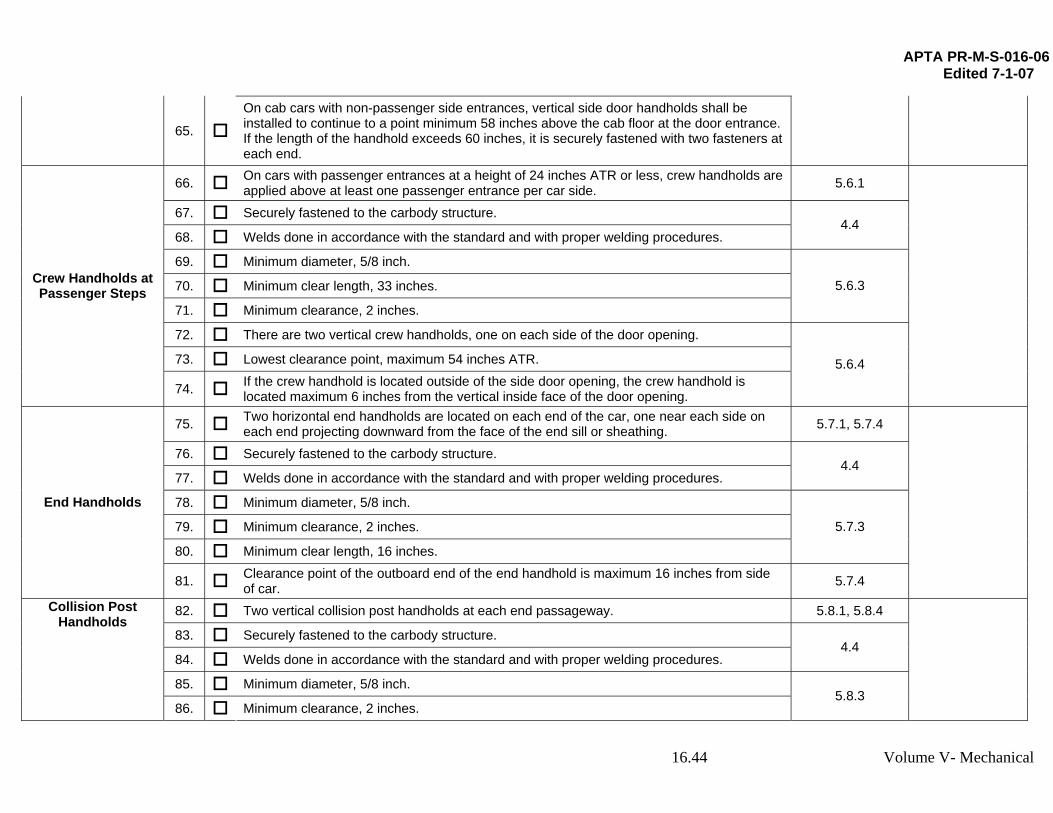
65. On cab cars with non-passenger side entrances, vertical side door handholds shall be installed to continue to a point minimum 58 inches above the cab floor at the door entrance. If the length of the handhold exceeds 60 inches, it is securely fastened with two fasteners at each end.
66. On cars with passenger entrances at a height of 24 inches ATR or less, crew handholds are applied above at least one passenger entrance per car side. 5.6.1
67. Securely fastened to the carbody structure.
68. Welds done in accordance with the standard and with proper welding procedures. 4.4
69. Minimum diameter, 5/8 inch.
70. Minimum clear length, 33 inches.
71. Minimum clearance, 2 inches.
5.6.3
72. There are two vertical crew handholds, one on each side of the door opening.
73. Lowest clearance point, maximum 54 inches ATR.
Crew Handholds at Passenger Steps
74. If the crew handhold is located outside of the side door opening, the crew handhold is located maximum 6 inches from the vertical inside face of the door opening.
5.6.4
75. Two horizontal end handholds are located on each end of the car, one near each side on each end projecting downward from the face of the end sill or sheathing. 5.7.1, 5.7.4
76. Securely fastened to the carbody structure.
77. Welds done in accordance with the standard and with proper welding procedures. 4.4
78. Minimum diameter, 5/8 inch.
79. Minimum clearance, 2 inches.
80. Minimum clear length, 16 inches.
5.7.3
End Handholds
81. Clearance point of the outboard end of the end handhold is maximum 16 inches from side of car. 5.7.4
82. Two vertical collision post handholds at each end passageway. 5.8.1, 5.8.4
83. Securely fastened to the carbody structure.
84. Welds done in accordance with the standard and with proper welding procedures. 4.4
85. Minimum diameter, 5/8 inch.
Collision Post Handholds
86. Minimum clearance, 2 inches. 5.8.3
16.44 Volume V- Mechanical

APTA PR-M-S-016-06 Edited 7-1-07
87. Lowest clearance point, maximum 44 inches above the walkway.
88. Highest clearance point, minimum 60 inches above the walkway. 5.8.4
89. Platform area enclosed with either a handrail or shortened walls. 5.9.1, 5.9.4
90. Railing and stile assembly may be welded but the ends of the final assembly must be securely fastened to the carbody structure. 4.4, 5.9.4
91. Welds done in accordance with the standard and with proper welding procedures. 4.4
92. Minimum handrail diameter, 1 inch.
93. Minimum wall thickness, 1/16 inch. 5.9.3
94. If intermittent handrail is used, end of the handrail is capped with a rounded end to reduce risk of injury.
95. Maximum distance from end of handrail to a vertical car member, 4 inches.
96. Minimum length from top of the platform floor to the top of the handrail, including entry doors, 42 inches.
97. Handrail designed such that a 5 inch diameter ball cannot pass through any space between handrail members or between the handrail and the carbody.
98. Handrail members shall not be unsupported for spans over 48 inches.
Handrail on Open Platform Cars
99. If shortened wall is used, it meets the location requirements for handrails as detailed above.
5.9.4
100. Each car has either a mechanical uncoupling device at each end of the car, located so that it can be operated from the left side of the car as seen when facing the end of the car from the ground, or an uncoupling mechanism operated by controls located in a secure location in the car.
5.10.1, 5.10.4
101. Securely fastened to the carbody structure.
102. Welds done in accordance with the standard and with proper welding procedures. 4.4
Only If Mechanically Operated From Side Of Car:
103.
Under all operating conditions, outside surface of uncoupling device handles maximum 14 inches closer to the car center than the inside surface of the adjacent side handhold.
104. Uncoupling attachments are applied so they can be operated by a person standing on
the ground.
105. Bottom end of the handle is between 12 and 15 inches below the centerline of the
outermost pivot point of the uncoupling lever to which the handle is attached.
Uncoupling Devices
106. Minimum 2 inches clearance around the handle at its end.
5.10.3
16.45 Volume V- Mechanical

APTA PR-M-S-016-06 Edited 7-1-07
107. Securely fastened to the carbody structure or supporting bracket. 5.10.5
108. Securely fastened to the carbody structure.
109. Welds done in accordance with the standard and with proper welding procedures. 4.4
110. Minimum useable length, 16 inches on side ladders and 14 inches on end ladders.
111. If rectangular cross section, treads are minimum 1/2 inch thick and minimum 2 inches wide.
112. If circular cross-section, minimum tread diameter, 5/8 inch.
113. Minimum tread clearance, 2 inches.
114. All ladder treads have foot guards.
5.11.2.2
115. Top ladder tread is between 12 inches and 18 inches below the mounting surface of the outboard end of the adjacent roof handhold.
116. Maximum spacing between ladder treads, 19 inches.
Elective Safety Appliance - Ladder
117. Spacing of side ladder treads is uniform within a limit of 2 inches, from top ladder tread to bottom tread of ladder.
5.11.2.3
118. Minimum diameter, 5/8 inch.
119. Minimum clear length, 16 inches.
120. Minimum clearance, 2 inches.
5.11.3.2
121. Securely fastened to the carbody structure.
122. Welds done in accordance with the standard and with proper welding procedures. 4.4
Elective Safety Appliance -
Roof Handhold
123. If roof handholds are located above a ladder, in the transverse direction, clearance points of the inboard end of roof handholds are maximum 8 inches inboard from and no further outboard than the clearance point of the inboard end of the top ladder tread.
5.11.3.3
16.46 Volume V- Mechanical