
158390067 NEC Pasolink 1 General Description
33
GENERAL DESCRIPTION 1 Pasolink+ XPIC Training Course. GENERAL DESCRIPTION CHAPTER 01
-
Upload
danilo-alves -
Category
Documents
-
view
79 -
download
3
description
Manual of configuration NEC Pasolink
Transcript of 158390067 NEC Pasolink 1 General Description

GENERAL DESCRIPTION 1
Pasolink+ XPIC Training Course.
GENERAL DESCRIPTION
CHAPTER 01
GENERAL DESCRIPTION 2
1. INTRODUCTION
NEC's Pasolink+ XPIC can operates in frequency bands from (6 – 38) GHZ.
NEC’s Pasolink+ XPIC supports the following transmission capacity:-
SDH 2 x STM-1 optical / electrical interfaces.
Optional 2 × 10/100 Base-T(X) LAN signal.
NEC’s Pasolink+ XPIC uses 128 QAM + RS modulation technique.
The following table shows a summary comparison for Pasolink family.

GENERAL DESCRIPTION 3
PASOLINK FAMILY
4/6GHz 7/8GHz 11GHz 13GHz 15GHz 18GHz 23GHz 26GHz 38GHz
SERIES/MODEL SYSTEM MODULATION INTERFACE 3.6-7.1 7.1-8.5 10.7-11.7 12.7-13.2 14.2-15.3 17.7-19.7 21.2-23.6 24.2-27 37-40
PASOLINK V3 PDH 4PSK
2x2MB
4x2MB
8x2MB
16x2MB
1x8MB
1x34MB
PASOLINK V4 PDH 4PSK
2x2MB
4x2MB
8x2MB
16x2MB
2x10/100Base-T
PASOLINK MX PDH 4PSK/16QAM
Selectable
5,10,20,40x2MB
2x10/100Base-T
PASOLINK+
PDH 16QAM + RS 8x2MB
16x2MB
SDH
(STM-0)
32QAM+RS 21x2MB
(STM-1)
SDH
(STM-1)
32 QAM +RS STM-1
SDH
(STM-1)
128QAM+RS STM-1
SDH
(2xSTM-1)
128QAM+RS STM-1
(XPIC)
2x10/100Base-T

GENERAL DESCRIPTION 4
2. EQUIPEMENT FEATURES (1/8)
1. ADVANCED TECHNOLOGIES AND SUPERB PERFORMANCE
• MMIC, HIC AND VLSI
• Single chip modulator/ demodulator (Full digital)
• Square-root Nyquist Roll-off shaping filter
• High reliability
• Low power consumption
2. HIGH TRANSMISSION CAPACITY
• 2 x 155 MB transmission capacity is realized by XPIC (Cross Polarization
Interference Canceller) technology.
3. MITIGATION OF INTERFERENCE
• Possible interference caused by co-channel transmission is mitigated with
orthogonal polarized input channel and the XPIC (Cross Polarization
Interference Canceller) device.
4. HIGH SYSTEM GAIN
• High system gain achieved by using 128 QAM + RS modulation techniques.
GENERAL DESCRIPTION 5
5. EASY AND QUICK INSTALLATION
• Very compact and light
• Only one coaxial cable interconnection
• Different mounting methods for IDU, ODU and Antenna
• Easy antenna pointing adjustments (RX level monitor point in ODU)
6. SYSTEM FLEXIBILITY
• Hot Standby/ Space Diversity / Twin Path systems are available with Hitless switch.
• Common IDU for different RF frequencies (6/7/8/11/13/15/18/23/26//38 GHz)
• (1 + 0 ) unprotected or ( 1+ 1) protected.
2. EQUIPEMENT FEATURES (2/8)
7. FREQUENCY AGILITY AND EASY TUNING
• Field tunable local-oscillator (Synthesizer).
• RF point frequency can be changed in the field, (except 6 – 8 GHz).
• Frequency Tunable without changing RF FIL on Sub-band basis (except 6 – 8 GHz).

GENERAL DESCRIPTION 6
8. TX POWER CONTROL
• Variable : 0 to 20 dB , 1 dB step variable.
• Automatic Transmit Power Control (ATPC) or Manual Transmit Power Control (MTPC)
9. EASY MAINTENANCE FACILITIES
• Full front panel access for all cabling and user interfaces
• Near End and Far End Base-band Loop back facilities
• Remote monitoring of ODU operating condition from IDU
• OW calling facility between IDU - ODU, IDU – IDU and ODU-ODU
• Local monitor and maintenance using Local Craft Terminal (LCT)
• Continuous RSL monitoring using Local Craft Terminal (LCT)
• Pre-settable BER alarm point.
2. EQUIPEMENT FEATURES (3/8)
• IF Loop back facility.

GENERAL DESCRIPTION 7
10. MULTIPLE SERVICE CHANNELS
• Engineering Order Wire (OW) : IDU- IDU (Standard)
IDU - ODU (In case using “PASOLINK MONITOR” (Option))
ODU-ODU (In case using “PASOLINK MONITOR” (Option))
• Service channels : - Digital Port : 64 kbps Sync., 2 ch standard.
VF Port : 0.3 to 3.4 kHz (1 ch) 600 ohms, 2 ch standard.
10 Base-T : 1 ch (optional; exclusive use in other service channels).
Cluster Alarm : 2 ch (optional; auxiliary alarm transmission).
• The system configuration is easily updated :-
1 x STM-1 (1+0) to 2 x STM-1 (1+0).
1 x STM-1 (1+0) to 2 x STM-1 (1+1 with hot standby).
1 x STM-1 (1+0) to 2 x STM-1 (1+1 with twin path).
11. COMMON PLATFORM ARCHITECURE.
2. EQUIPEMENT FEATURES (4/8)

GENERAL DESCRIPTION 8
• Complies with ETS 300385
15. ELECTRO MAGNETIC COMPATIBILITY (EMC)
14. CONFORMITY WITH ANSI, ITU-R, ITU-T AND ETSI STANDARDS
2. EQUIPEMENT FEATURES (5/8)
• NEC Quality control is carefully monitored in every manufacturing step, such as parts
selection, assembly, adjustment and testing.
• NEC Quality Controls employing Zero Defect and Value Engineering Techniques extend to
every aspect of production and inspection in accordance with stringent Total Quality Control
programs.
12. RELIABILITY AND QUALITY
• User friendly operation as maintenance terminal.
13. PASOLINK NETWORK MANAGEMENT TERMINAL (PNMT) (OPTION)
• Link oriented monitor and control.
• Uses Windows 2000/XP which enable use of mobile PC

GENERAL DESCRIPTION 9
16. PASOLINK NETWORK MANAGEMENT SYSTEM (PNMS) (OPTION)
• User friendly operation
• Uses Windows 2000/XP to ensure easy operation and maintainability
• Remote access and control of any PASOLINK Terminal in the network
• Link oriented monitor and control ( both side of a microwave link)
• Multi level security
• Event Logging
• ITU-T G.826 Performance Monitor (Table /graph presentation)
• Real-time monitor of Network Elements (NE)
• SNMP Interface (Option)
2. EQUIPEMENT FEATURES (6/8)

GENERAL DESCRIPTION 10
17. Flexible ODU Mounting Configurations.
2. EQUIPEMENT FEATURES (7/8)
Suitable configuration can be selected from various ODU mounting styles.
1. Direct Mounting on Antenna.
2. Remote Mounting with Waveguide or Coaxial Cable.
2. 11-38 GHz Remote Mount Dual Pole System 1. 6-8 GHz Remote Mount Dual Pole System

GENERAL DESCRIPTION 11
17. Flexible ODU Mounting Configurations (Cont.)
2. EQUIPEMENT FEATURES (8/8)
3. 11-38 GHz Direct Mount Dual Pole System

GENERAL DESCRIPTION 12
3. Compatibility

GENERAL DESCRIPTION 13
4. System Compositions
The system consists of the following :-
1. MDP-150MB7T-( )A Modulator-Demodulator (Indoor Unit (IDU)).
2. TRP-( )G-1AA Transmitter-Receiver (Outdoor Unit (ODU)).
3. Orthogonal Mode Transducer (OMT) (for antenna direct mounting).
4. Hybrid for 1+1 one antenna configurations.
5. Antenna for required MW band.
6. IF Cable.
7. RF Cables for ODU Remote mounting.

GENERAL DESCRIPTION 14
5. IDU Composition for 1+0

GENERAL DESCRIPTION 15
6. IDU Composition for 1+1

GENERAL DESCRIPTION 16
7. IDU Performance Characteristics (1/3)

GENERAL DESCRIPTION 17
7. IDU Performance Characteristics (2/3)

GENERAL DESCRIPTION 18
7. IDU Performance Characteristics (Cont.) (3/3)

GENERAL DESCRIPTION 19
8. ODU Indication Label

GENERAL DESCRIPTION 20
9. ODU Composition for (6/7/8 GHz)

GENERAL DESCRIPTION 21
10. ODU Composition for (11/13/15 GHz)

GENERAL DESCRIPTION 22
10. ODU Composition for (18/23/26/38 GHz)

GENERAL DESCRIPTION 23
11. ODU Performance Characteristics.
GENERAL DESCRIPTION 24
12. OMT (Ortho Mode Transducer). (1/3)
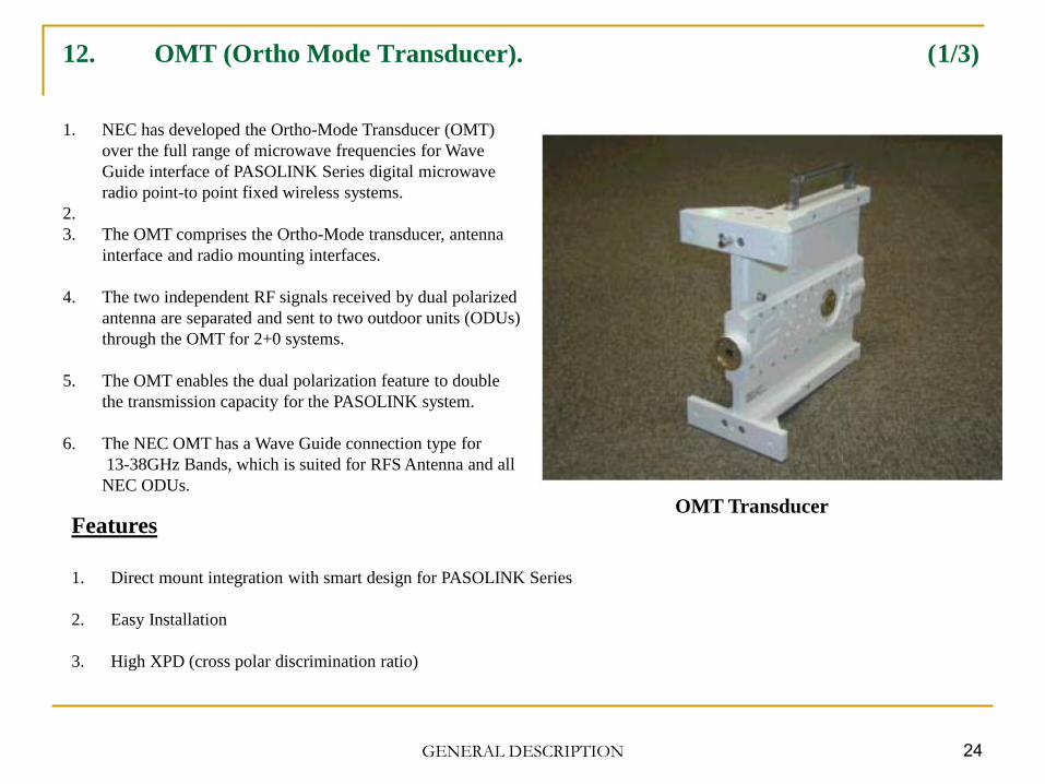
OMT Transducer
1. NEC has developed the Ortho-Mode Transducer (OMT)
over the full range of microwave frequencies for Wave
Guide interface of PASOLINK Series digital microwave
radio point-to point fixed wireless systems.
2.
3. The OMT comprises the Ortho-Mode transducer, antenna
interface and radio mounting interfaces.
4. The two independent RF signals received by dual polarized
antenna are separated and sent to two outdoor units (ODUs)
through the OMT for 2+0 systems.
5. The OMT enables the dual polarization feature to double
the transmission capacity for the PASOLINK system.
6. The NEC OMT has a Wave Guide connection type for
13-38GHz Bands, which is suited for RFS Antenna and all
NEC ODUs.
Features
1. Direct mount integration with smart design for PASOLINK Series
2. Easy Installation
3. High XPD (cross polar discrimination ratio)

GENERAL DESCRIPTION 25
12. OMT (Ortho-Mode Transducer) (Cont.) (2/3)
OMT Physical Dimensions

GENERAL DESCRIPTION 26
12. OMT (Ortho-Mode Transducer) (Cont.) (3/3)
OMT Specifications

GENERAL DESCRIPTION 27
13. Hybrid Combiner / Divider. (1/4)
6/7/8 GHz Hybrid 13 – 38 GHz Hybrid
NEC has developed the Hybrid Combiner/Divider over the full range of microwave frequencies for the
PASOLINK Series digital microwave radio point-to-point fixed wireless systems.
This Hybrid Combiner/Divider comprises a directional coupler, antenna interface, radio mounting interfaces and
polarizer.
The RF signal power received by the single polarized antenna is equally distributed and sent to two outdoor units
through the Hybrid Combiner/Divider for 1+1 protected systems.
There are two types of NEC Hybrid Combiner/Divider, one is a coaxial cable connection type for 6/7/8GHz
Bands and the other is WG connection type for 13-38GHz Bands.
NEC Hybrid Combiner/Divider is suited for Andrew, RFS, or PAL Antenna, and all NEC ODUs.

GENERAL DESCRIPTION 28
13. Hybrid Combiner / Divider. (Cont.) (2/4)
7/8 GHz Hybrid Physical Dimensions

GENERAL DESCRIPTION 29
13. Hybrid Combiner / Divider. (Cont.) (3/4)
13 - 38 GHz Hybrid Physical Dimensions

GENERAL DESCRIPTION 30
13. Hybrid Combiner / Divider. (Cont.) (4/4)
13 - 38 GHz Hybrid Specifications

GENERAL DESCRIPTION 31
14. Pasolink Antenna menu and performance for direct mount types.
Note 1:
18-38GHz antennas are provided with
standard waveguide flange (PBR) and
PASOLINK original interface.
(13-15GHz antennas are provided with
PASOLINK original interface and
without standard waveguide flange.)
Note 2:
In case of 7,8,13 and 15GHz remote
mount configuration, please don’t use
this table.
(Please refer to the standard catalog of
the antenna supplier).
Note 3:
This table shows typical values for
reference.
Note 4:
In case of Dual Pole Direct Mount
Antenna System, * marked Diameters
are available.
GENERAL DESCRIPTION 32
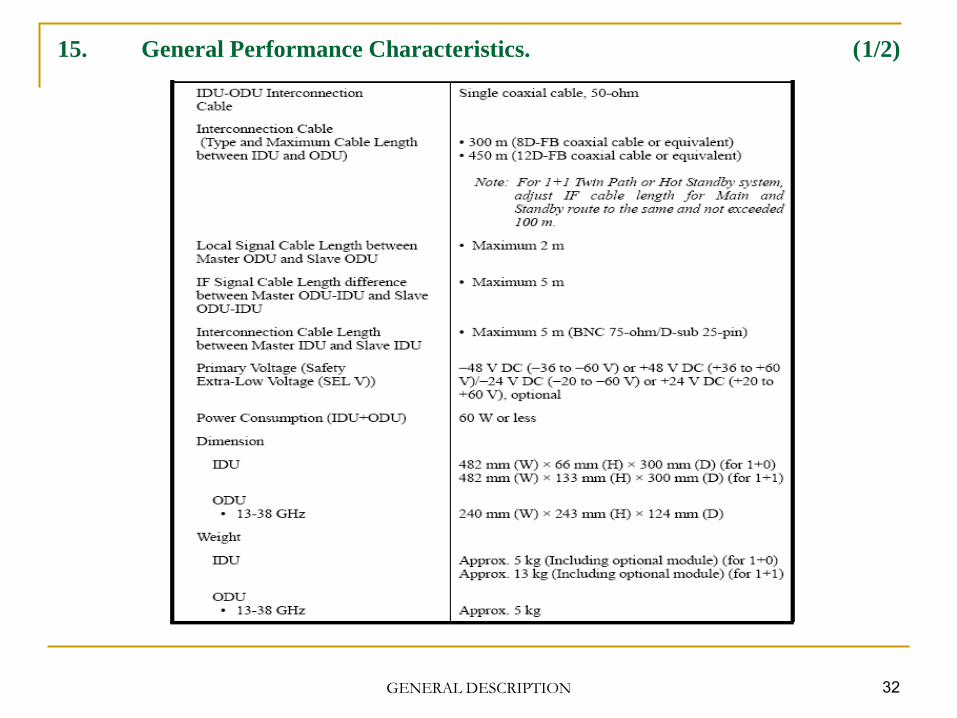
15. General Performance Characteristics. (1/2)
GENERAL DESCRIPTION 33
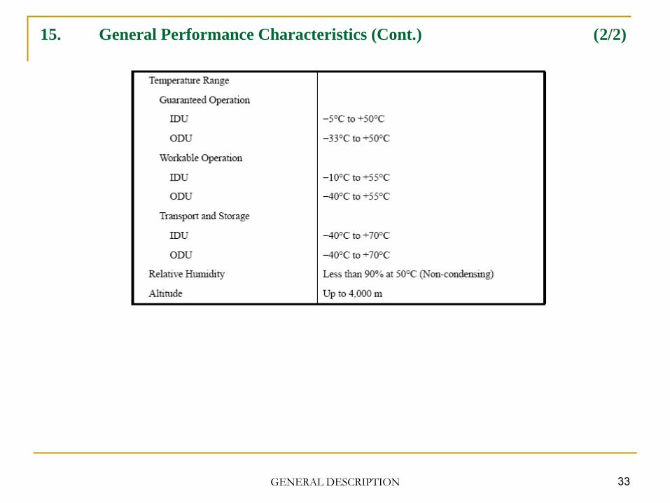
15. General Performance Characteristics (Cont.) (2/2)


![88847687 Microwave Nec Pasolink Neo by Akash Ray[1]](https://static.fdocuments.in/doc/165x107/544cb47bb1af9fc2498b47fc/88847687-microwave-nec-pasolink-neo-by-akash-ray1.jpg)