1//55 PPTT--1177 SSTTEEAARRMMAANN AARRFF PPTT--1177 SSTTEEAARRMMAANN AARRFF RAADDIIOO...
18
Page 1 of 18 Copyright 2015 – PT17 / S150727 Entire contents – Copyright 2014 1 1 / / 5 5 P P T T - - 1 1 7 7 S S T T E E A A R R M M A A N N A A R R F F RADIO CONTROLLED MODEL AIRPLANE INSTRUCTION MANUAL Congratulations on your acquisition of a Maxford USA ARF PT-17 Stearman! The PT-17 is a biplane that was used as a military trainer by the US Army Air Corps during the 1930s and served throughout WWII. The PT-17 is also widely known as the Stearman, Boeing Stearman, Boeing Model 75, or the Kaydet. At least 9,783 were built and thousands of surplus PT-17s were sold on the civil market after the conflict. This almost-ready-to-fly radio-control version of the PT-17 is based on the aircraft that is owned by John Mohr, who very kindly sent us many detailed pictures of his personal aircraft. We also acknowledge and thank Jay Smith, editor or Model Aviation, for his help and advice on this project. This model is constructed mainly of laser-cut balsa and light plywood. As shown above, it is finished with a Mylar film covering. It may also be special-ordered with a flat-finish Mylar or as a fabric-covered and prepainted ARF. We invite you to enjoy the pride of ownership and the joy of flying your high- quality balsa and light-ply almost-ready-to-fly version of this historic aircraft. TABLE OF CONTENTS I. Important safety precautions & assembly tips .... 2 II. Warranty, liability waiver, and return policy ..... 3 III. Special features of this Nieuport 28 model ........ 4 IV. Specifications ..................................................... 4 V. Parts List ............................................................. 4 VI. Assembly photo-instructions .......................... 5 VII. Setup and adjustments .................................. 17 VIII. Preparation for transport and field setup ...... 17 IX. Preflight checks ............................................ 18 Shown with optional upgraded scale dummy engine, electric motor and propeller.
-
Upload
truongkiet -
Category
Documents
-
view
220 -
download
3
Transcript of 1//55 PPTT--1177 SSTTEEAARRMMAANN AARRFF PPTT--1177 SSTTEEAARRMMAANN AARRFF RAADDIIOO...

Page 1 of 18 Copyright 2015 – PT17 / S150727 Entire contents – Copyright 2014
11//55 PPTT--1177 SSTTEEAARRMMAANN AARRFF RRAADDIIOO CCOONNTTRROOLLLLEEDD MMOODDEELL AAIIRRPPLLAANNEE
II NN SS TT RR UU CC TT II OO NN MM AA NN UU AA LL
Congratulations on your acquisition of a Maxford USA ARF PT-17 Stearman!
The PT-17 is a biplane that was used as a military trainer by the US Army Air Corps during the 1930s and served throughout
WWII. The PT-17 is also widely known as the Stearman, Boeing Stearman, Boeing Model 75, or the Kaydet. At least 9,783 were
built and thousands of surplus PT-17s were sold on the civil market after the conflict.
This almost-ready-to-fly radio-control version of the PT-17 is based on the aircraft that is owned by John Mohr, who very
kindly sent us many detailed pictures of his personal aircraft. We also acknowledge and thank Jay Smith, editor or Model
Aviation, for his help and advice on this project.
This model is constructed mainly of laser-cut balsa and light plywood. As shown above, it is finished with a Mylar film
covering. It may also be special-ordered with a flat-finish Mylar or as a fabric-covered and prepainted ARF.
We invite you to enjoy the pride of ownership and the joy of flying your high-
quality balsa and light-ply almost-ready-to-fly version of this historic aircraft.
TABLE OF CONTENTS
I. Important safety precautions & assembly tips .... 2
II. Warranty, liability waiver, and return policy ..... 3
III. Special features of this Nieuport 28 model ........ 4
IV. Specifications ..................................................... 4
V. Parts List ............................................................. 4
VI. Assembly photo-instructions .......................... 5
VII. Setup and adjustments .................................. 17
VIII. Preparation for transport and field setup ...... 17
IX. Preflight checks ............................................ 18
Shown with optional upgraded scale dummy
engine, electric motor and propeller.
Page 2 of 18 Copyright 2015 – PT17 / S150727
I. SAFETY PRECAUTIONS & ASSEMBLY TIPS:
(IMPORTANT – READ THIS SECTION BEFORE YOU BEGIN ASSEMBLY)
1. This product should not be considered a toy, but rather a sophisticated, working model that functions much like a full-scale
airplane. Because of its performance capabilities, this product, if not assembled and operated correctly, could cause injury
to you or spectators and damage to property. Maxford USA provides you with a high-quality, thoroughly tested model
airplane kit with assembly instructions. However, the quality and capabilities of your finished model airplane depend on
how you assemble it, and your safety depends on how you use and fly it. Any testing or flying of this model airplane is
done entirely at your own risk.
2. Assemble this model airplane according to these instructions. Do not alter or modify the model beyond the assembly and
power system options covered in these instructions, as doing so may result in an unsafe or unworkable model. In a few
cases the instructions may differ slightly from the photos; in those instances the written instructions should be considered
as correct. If you have a question or concern about these instructions, before you proceed with assembly of this product,
contact your dealer or speak to a Maxford USA customer service representative at 562-529-3988 (Monday through Friday,
except national holidays, 9 AM to 5 PM Pacific time).
3. While this kit has been flight-tested to meet or exceed our rigid performance and reliability standards in normal use, if you
elect to perform any extremely high-stress flying, such as racing or advanced aerobatics, or if you install a larger power
system than specified, you (the buyer or user of this product) are solely responsible for taking any and all necessary steps
to reinforce the high-stress points and/or substitute hardware that is more suitable for such increased stresses.
4. Throughout the lifetime of this model, use only the Maxford USA-recommended or same-sized engine or motor and a new
or well-maintained radio control system and batteries recommended by the maker of your motor and radio system.
5. It is your responsibility to install the R/C system and other components in such a way that this model airplane passes all
applicable safety/range tests and that the power system and controls operate correctly and smoothly.
6. Recheck the operation of this model airplane before every flight to ensure that all equipment is still operating correctly and
that the model has remained structurally sound. Also before every flight, check all electrical and structural connections; do
not fly without properly connecting or replacing any that you find poorly connected, damaged or worn.
7. Before you begin assembly of this model airplane, read all instructions and test-fit each part to ensure you fully understand the
instructions and that no parts are missing, damaged or unsatisfactory. Temperature and/or humidity differences between the
factory, our warehouse and your home or workshop may dictate the need for slight adjustments to the wings, struts and/or the
vertical or horizontal stabilizer‟s mounting surfaces to ensure proper alignment; however, we recommend you contact us before
you attempt any such adjustment(s).
8. To help ensure the security of any in-line servo-type connections, optional Maxford USA servo-extension
safety clips are recommended.
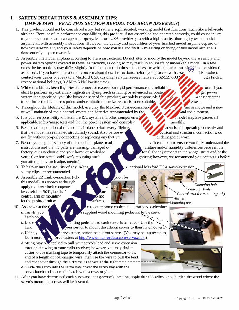
9. Assemble EZ Link connectors (whether included or an option for
this model). As shown at the right, when
applying threadlock compount or CA adhesive,
be careful to NOT glue the EZ Link connector to the
control arm or mounting tab; also be careful to not
let the pushrod rub or bind against nearby surfaces.
10. As shown at the right, this model allows customers some choice in aileron servo selection:
a. Test-fit your aileron servos and the supplied wood mounting pedestals to the servo
hatch covers.
b. Use epoxy to attach the mounting pedestals to each servo hatch cover. Use the
hardware provided with your servos to mount the aileron servos to their hatch covers.
c. Using your radio or a servo tester, center the aileron servos. (You may be interested to
learn more about servo testers at http://www.maxfordusa.com/servo.aspx.)
d. String may be supplied to pull your servo‟s lead and servo extension
through the wing to your radio receiver; however, you may find it
easier to use masking tape to temporarily attach the connector to the
end of a length of coat-hanger wire, then use the wire to pull the lead
and connector through the airframe as shown at the right.
e. Guide the servo into the servo bay, cover the servo bay with the servo-hatch and secure the hatch with screws or glue.
11. After you have determined each servo-mounting-screw‟s location, apply thin CA adhesive to harden the wood where the
servo‟s mounting screws will be inserted.
Clamping bolt
Connector body
Control arm (or mounting tab)
Washer
Mounting nut

Page 3 of 18 Copyright 2015 – PT17 / S150727
12. If Mylar hides a CA hinge‟s slot, find and open the slot by carefully pressing with a fingernail or sharp hobby knife.
13. Use the tip of a hot soldering iron to burn and remove any Mylar covering material to obtain good wood- to-wood gluing
surfaces at the horizontal and vertical stabilizers.
14. We recommend 30-minute epoxy for permanent attachment of critical parts such as where the horizontal and vertical
stabilizers attach to the fuselage.
15. If you have concern about the security of any factory fabrication procedure(s), we recommend you apply 30-minute epoxy
around the perimeter of such part(s) as an extra safety precaution.
16. We recommend use of a thread-locking compound to secure all hardware from
vibration. Also, once the included clevises are adjusted, we suggest you coat
each clevis and rod with epoxy to securely and safely affix each clevis to its rod.
As a safety precaution, always check each clevis before and after each flight.
17. This model includes some fiberglass or carbon-fiber reinforced parts. If you drill,
grind or sand a fiberglass or carbon-fiber reinforced part, always wear safety
goggles, a particle mask and rubber gloves to guard yourself from eye, skin and respiratory-tract irritation; never blow into
the part to remove fiberglass or carbon fiber dust (the dust may blow back into your face).
18. Check the Mylar covering material‟s joints and surfaces; if necessary, carefully use an iron
(do NOT set the iron‟s temperature too high) to secure the edges and to tighten any loosened
areas. Recheck and retighten from time to time.
19. For your safety, do NOT leave any strands of wire poking out from the end of any crimp tube.
Exposed small steel strands can be sharp enough to cut or abrade skin!
20. Minor production details may vary.
21. If you are not an experienced ARF assembler or R/C pilot or have not flown this type of model before, we strongly urge
you to get assistance from an experienced ARF assembler or R/C pilot.
22. Periodically check any preinstalled magnets to ensure they remain securely postitioned.
23. Read all instructions included with your batteries and charger. Failure to follow all instructions could result in permanent
damage to the battery, its surroundings, and bodily harm! If you crash this model airplane, check whether the batteries are
damaged. Do NOT attempt to use or recharge a damaged battery.
II. WARRANTY, LIABILITY WAIVER, AND RETURN POLICY Maxford USA guarantees this kit to be free from defects in material and workmanship at the time of purchase. All of our
products have been inspected in our factory and are checked again when shipped from our warehouse.
However, Maxford USA cannot directly control the materials you may use nor your final-assembly process. Therefore,
Maxford USA can NOT in any way guarantee the performance of your finished model airplane. Furthermore, in purchasing
this product, you (the buyer or user of this product) exempt, waive, and relieve Maxford USA from all current or future
liability for any personal injury, property damage, or wrongful death, and if you (the buyer or user of this product) are
involved in any claim or suit, you will not sue Maxford USA or any of its representatives.
If you do not fully accept the above liability and waiver, you may request a return merchandise authorization number
(RMA#) as explained in item 2, below.
If you think there is a missing part or any shipping damage, please read our after-sales service and return policy as outlined
below.
1. Inspect your order upon delivery for any shipping damage or missing part. If you find a problem you must contact us within
10 days from receipt of your purchase by calling (562) 529-3988, Monday through Friday, except holidays, between the
hours of 8:30 AM and 5 PM Pacific time. During this telephone conversation, and with your support, we will determine how
to resolve your concern. (Note: Maxford USA batteries are sold without warranty and are not eligible for return or credit.)
2. To request an RMA#, call (562) 529-3988, Monday through Friday, except holidays, between the hours of 8:30 AM to 5 PM
Pacific time. If we elect to issue you an RMA#, you must clearly mark this RMA# on the outside of the package. (No return
or exchange will be authorized after 10 days from the date of your receipt of the product; any package delivered to us without
a Maxford USA RMA# is subject to being returned to the sender, as received, with return postage payable upon delivery.)
Returned merchandise must be in its original condition as received from Maxford USA, with no assembly or modification, in
the original packing materials, complete with all manuals and accessories. Return shipping and insurance charges must be
prepaid by you, the buyer.
3. Returned merchandise that is accepted by Maxford USA for credit is subject to a 10% to 20% restocking fee (the final
amount will be determined by Maxford USA upon receipt and examination of the returned merchandise).
Return Address: Maxford USA RC Model Distribution, Inc.
15939 Illinois Avenue #C
Paramount, CA 90723 (Print the RMA# issued by Maxford USA on the package near the address.)

Page 4 of 18 Copyright 2015 – PT17 / S150727
III. SPECIAL FEATURES OF THIS PT-17 MODEL
Wing panel sets are removable
for ease of storage and transport.
Includes a plastic dummy engine.
An optional built-up wood
dummy engine is available as an
upgrade.
Each aileron is operated by its
own in-wing servo (servos not
included).
Steerable tail wheel – controlled
by a dedicated tail wheel steering
servo (servos are not included
with this ARF).
Streamlined landing
gear.
Pull-pull rudder cables.
Stick-on decal set.
Wing support kit is
included for safe
transport and storage.
Dashboard set available
as an optional upgrade,
includes an LED
radio-system voltage
indicator, radio-power
switch and charge-
connector.
IV. SPECIFICATIONS
Wingspan ................................................................................................................................ 77 inches
Wing Area .............................................................................................................. 1,686 square inches
Length ..................................................................................................................................... 57 inches
ARF weight .................................................................................................... 14 pounds and 4 ounces
Flying weight ................................................................................................ 15 pounds and 14 ounces
Engine required (Not included) ...................... 90 to 120 glow or an equivalent electric power system
such as the Uranus 638109 brushless motor and 100 Amp High Voltage Brushless Controller
Propeller (Not included) ................................................................................................... 18 to 20 inch
(as recommended for your power system)
Radio system (Not included) ....................................... Minimum of 4 channels and 5 standard servos
(a 6th servo is needed to control the throttle if a gas or glow engine is used)
(All dimensions and weights are approximate.)
V. PARTS LIST
1. Items you must supply to complete this PT-17:
5- and 30-minute epoxy or aliphatic resin glue, thin and thick Cyanoacrylate (CA) adhesives.
Pliers, Allen wrenches, a high speed rotary tool, scissors and masking tape.
90 to 120 glow engine, or an equivalent-powered motor system.
(See http://www.maxfordusa.com/brushlessmotorandcontroller.aspx
for detailed information about Maxford USA electric power systems.)
Propeller.
Five standard-sized servos (four standard servos if you use an electric power
system), two 18-inch extensions, one 6-inch
Y-connector, and a minimum of a 4-channel
radio-control system.
Optional upgrade items:
Dashboards with switch for
receiver, charge jack and a
battery voltage monitor; scale
pilot figure(s); upgraded
balsa and light ply dummy
engine.
*
*
Optional Uranus 638109
brushless motor (above)
and 100 Amp
High Voltage Brushless
Electronic Speed Control
(shown below)
Optional upgraded
balsa and light ply
dummy engine

Page 5 of 18 Copyright 2015 – PT17 / S150727
2. Items included with this PT-17:
Prepainted plastic dummy radial engine.
Precovered fuselage, upper and lower-wing
panels, upper-wing‟s center section, vertical
and horizontal stabilizers, rudder and elevator,
with precut hinge openings.
All necessary hardware for pull-pull cables for
rudder and tail wheel and pushrods for ailerons
and elevator.
Wing-rod joiners, preformed cabanes and struts,
and all required control horns, hinges, linkages,
wing wires, tail braces and related hardware.
Streamlined landing gear with scale-like wheels.
Complete set of scale markings.
Magnetically-secured cockpit-hatch assembly.
VI. ASSEMBLY PHOTO-INSTRUCTIONS
1. Using the mounting hardware supplied with your
motor or a mount recommended for your engine
(not supplied), test-fit your motor or glow engine
to the forward-facing surface of the engine
mounting box („firewall‟). Center the propeller
shaft on the intersecting lines on the firewall
that form an „X.‟ Mark the firewall where
openings are needed for mounting your motor or
engine. If you are using a glow engine, point the engine‟s cylinder head toward the
ground. (Use the “L” and “R” on the sides of the engine mounting box as viewed
from the pilot‟s seat to determine which way is “down.”)
2. If you are using a glow engine: Decide where to
install your throttle servo and mark where to
make an opening for the throttle pushrod and
fuel line (not supplied).
3. Form all necessary openings in the firewall.
Mount your engine or motor onto the firewall
(use threadlock compound to help protect the
motor or engine mounts from vibration).
4. Insert the engine mounting box into the fuselage with the side marked “L” toward
the pilot‟s left-hand side to maintain the right and down thrust built into the engine
mounting box‟s firewall.
5. If you use an electric motor: Test-fit the dummy engine over your motor and to the
PT-17‟s nose. If you use a glow engine: As pictured below, remove one dummy-
engine cylinder and its adjoining crankcase to test-fit the dummy engine over your
glow engine; also remove material from a neighboring cylinder to make room for
your engine‟s exhaust pipe and muffler if necessary.
NOTE: The
unpainted dummy
engine pictured in
several places in
this manual is a
prototype; details
of construction
may vary. All
dummy engines
produced for this
ARF will be
prepainted when
shipped.

Page 6 of 18 Copyright 2015 – PT17 / S150727
6. Test-fit the dummy engine over your electric
motor or glow engine and to the PT-17‟s nose
and adjust the depth of the engine mounting
box in the fuselage to position the propeller for
a minimum of 1/4-inch clearance in front of the
dummy engine as shown at the right.
7. If a glow engine is used,
install and connect your
throttle pushrod and fuel
line (not supplied).
8. When satisfied with the
position and fit of your
electric motor or engine,
propeller and dummy
engine, use glue or wood
screws to secure the
engine mounting box into
its opening inside the
fuselage as pictured
below. (NOTE: Possible future repairs are
more difficult if the engine mounting box
is glued.)
9. If you use a glow engine: Install the fuel
tank inside the engine mounting box. If
you use an electric motor: Insert a piece of
foam rubber (not included) inside the
front of the engine mounting box to
cushion and protect your flight battery.
10. Use epoxy to glue 3 pieces of wood spaced
equally behind the nose ring. When the
glue is fully cured, secure the dummy
engine to the nose by driving 3 wood
screws through the dummy engine‟s
mounting ring, through the nose ring and
into the added wooden.
(SUGGESTION: Drill small guide holes
before driving in these wood screws.)
11. Slide the upper ends of the landing gear‟s
struts into their slots in the fuselage.
12. Secure the struts to the fuselage by driv-
ing bolts into the blind nuts preinstalled in the fuselage.
13. Slide the lower wing‟s composite wing rods into their openings and midway through the fuselage.
14. Test-fit the elevator joiner and both halves of the horizontal stabilizer into their openings at each side of the fuselage.
(NOTE: Position the horiz. stab. fully forward for clearance to insert the elevator joiner in step 51 on page 9.)
15. To ensure good wood-to-wood glueing surfaces between the horizontal stabilizer
and the fuselage, remove the Mylar from the parts of the horizontal stabizer that will be captured inside the openings in the fuselage as pictured at the right.
Secure the engine mounting box to the
fuselage with glue and/or wood screws
Shown with a glow engine
Shown with an
electric motor

Page 7 of 18 Copyright 2015 – PT17 / S150727
16. Use 30 minute
epoxy to secure the
horizontal stabilizer
into its openings in
the fusealge. As
shown at the right:
Visually compare
the horiz. stab. to
the wing rods, then apply masking tape to hold the horizontal stabilizer parallel to the lower wing‟s wing rods until the
epoxy is cured fully.
17. Attach an EZ Link connector to the supplied tailwheel‟s control arm as shown below.
18. Test-fit your tail wheel servo, its
output arm, the tailwheel‟s strut, a
wheel collar and the control arm to
the bottom of the tail as shown at
the right.
19. Position a wheel
collar onto the
tailwheel strut
inside the
opening on the
right side of the
tail.
20. As shown at the right, test-fit the tailwheel fairing to determine how far the tail-
wheel strut should extend into the tail, then set the tailwheel fairing aside.
21. Test-fit the tailwheel pushrod between your tailwheel servo and the EZ Link
connector.
22. Temporarily position the tail wheel onto its strut.
23. Center the tail wheel strut and your tailwheel servo. Cut the tailwheel‟s pushrod
to fit between your servo and the EZ Link connecter as shown above.
24. Remove the tail wheel from the tailwheel strut.
25. Attach an 18-inch servo extension to your tailwheel servo. (NOTE: Depending
on the length of your servo‟s lead and where you position your receiver, a longer
tailwheel servo extension might be needed; we recommend using an optional
Maxford USA servo-extension safety clip to secure the extension to your
tailwheel servo‟s lead.)
26. Guide the tailwheel servo extension forward into the cockpit area.
27. Mount the tailwheel servo into its tray with its provided hardware.
28. Double-check to ensure the tail wheel strut extends far enough to clear the
tailwheel fairing. Secure both wheel collars and the tailwheel control arm onto
the tailwheel strut.
29. Securely tighten the EZ Link connector onto the tailwheel‟s pushrod.
30. Position the tailwheel fairing over the tailwheel strut and attach it with the
provided wood screws, or you may attach the tailwheel fairing with glue if being
able to perform adjustments or repairs is not a concern.
31. Trim the portion of the tailwheel fairing that extends beyond the end of the
fuselage.
32. As pictured on the following page, test-fit the vertical stabilizer into its opening
above the horizontal stabilizer. Using CA hinges, test-fit the rudder onto its
control rod behind the vertical stabilizer.
EZ Link connecter
Tailwheel pushrod

Page 8 of 18 Copyright 2015 – PT17 / S150727
33. Ensure good wood-to-wood glueing surfaces
between the vertical stabilizer and fuselage
by removing the Mylar from the parts of the
horizontal stabizer that will be captured
inside this opening as pictured below.
34. Use 30 minute epoxy to secure the vertical
stabilizer into its opening in the fusealge.
Visually compare to ensure the vertical
stabilizer is at 90-degrees to the horizontal
stabilizer.
35. Test-fit 2 CA-hinges between the rudder and
the vertical stabilizer above the predrilled opening in the rudder
for the rudder‟s control rod.
36. As shown at the
right, inside the
opening on the
right side of the
tail, test-fit the
rudder‟s pull-pull
control arm onto
the lower end of
the rudder‟s
control rod and
the lower end of the rudder‟s control rod into its opening in the „floor‟ of this opening.
37. Remove and temporarily set aside the rudder, its CA-hinges, and the rudder‟s pull-pull control arm.
38. Cut 2 lengths of 27 1/2 inch (70 cm) cable to use as rudder pull-pull cables from the longer supplied stranded steel cable.
39. Use crimp tubes to attach one cable to each end of the rudder‟s
pull-pull control arm.
40. Guide the free ends of these cables through the opening on the
right side of the tail and forward all the way into the cockpit area.
41. Position the rudder‟s control rod into its opening in the „floor‟ of
the compartment on the right side of the tail.
42. Align the rudder to the control arm and tighten the screw to secure the rudder‟s pull-pull control
arm to the rudder‟s control rod.
43. Insert a staight pin through the center of both of the rudder‟s CA hinges.
(NOTE: During assembly, these pins keep the CA hinges centered and
help to ensure there is enough space between the rudder and the vertical
stabilizer to allow the rudder to freely move to the left and right.)
44. Apply 5-minute epoxy to the end of the rudder‟s control rod.
Immediately guide the opening in the rudder on onto its control rod
and insert the CA hinges between the rudder and vertical stabilizer.
45. Apply CA adhesive to permanently attach the rudder to the vertical stabilizer. Remove the pins
from the CA hinges after the CA adhesive has fully polymerized.
46. Use your radio or a servo tester to center your rudder and elevator servos. (NOTE: You may learn
about servo testers at http://www.maxfordusa.com/servo.aspx.)
Rudder’s control rod.
Rudder’s pull-pull control arm.

Page 9 of 18 Copyright 2015 – PT17 / S150727
47. Use the hardware provided with a standard-sized servo to install your rudder servo in the front/lower opening of the
servo tray as shown below.
48. Align the rudder to your elevator servo‟s output arm. Attach the rudder‟s pull-pull cables to the rudder servo using your
choice of either of the methods described below:
a) Draw the cables snug and use crimp tubes, as
shown below.
b) Draw the cables snug and use crimp tubes with threaded
rods and clevises to allow for fine-tuning adjustments, as
shown below.
49. Use the hardware provided with another standard-sized servo to
install the elevator servo in its servo tray above and behind the
rudder servo.
50. Attach a clevis and the elevator pushrod to the control arm
on the left side of the elevator servo.
51. Insert the metal elevator
joiner through the tail
section in the space
behind the horizontal
stabilizer as shown at the
right.
52. Test-fit both halves of the elevator
onto the metal joiner. At the same
time, test-fit CA-hinges between the
elevator and horizontal stabilizer.
(NOTE: Use pins to center the CA
hinges and to ensure enough space
between each half of the elevator and the horizontal stabilizer so the elevator can move up and down freely
at least 2-inches/5 cm from level with the horizontal stabilizer.)
53. As shown at the right, install a control horn assembly in the the bottom of the right side‟s elevator and
attach an EZ Link connector to the elevator‟s control horn.
54. Apply CA adhesive to permanently attach each half of the elevator to its metal joiner, to its CA hinges and
to the horizontal stabilizer. Remove these pins after the CA adhesive has fully polymerized.
55. As shown at the right,
guide the tail wheel‟s
fairing over the tail wheel
strut and onto the tail.
56. Test-fit the tail wheel‟s
fairing to the bottom-rear
(tail) of the fuselage.
57. Secure the tail wheel‟s
fairing to the fuselage
using your choice of glue,
transparent tape or screws.
58. Guide the elevator pushrod
into the opening on the
EZ Link connector and apply 5-minute epoxy to the ends of the the elevator joiner.
59. Insert both halves of the elevator onto the joiner and slide the elevator‟s CA hinges into their slots. Immediately apply CA adhesive to permanently attach the elevator to the horizontal stabilizer. Remove the pins from the CA hinges after
the CA adhesive has fully polymerized.
Tail wheel’s fairing

Page 10 of 18 Copyright 2015 – PT17 / S150727
60. Hold your elevator at neutral (on the same level as the horizontal stabilizer) and tighten the EZ Link connector onto the
elevator pushrod.
61. If necessary, cut off the portion of the elevator
pushrod that extends excessively behind the
elevator servo‟s EZ Link connector.
(NOTE: Leave approx. 1/2-inch of
extra pushrod for possible adjustments).
62. If you use a glow engine, install your throttle
servo and connect the throttle pushrod between
your engine and throttle servo.
(NOTE: For better appearance and
airframe longevity, we recommend
using an electric power system for
this model. For scale-like flying
using our U638109 motor, 100A
ESC and a 19x6 propeller, you
may use two 4S/4,000 mAh or
above LiPo batteries in series. For
extra power, we recommend using
a 10S or 12S/3,900mAh or above
LiPo battery – or three 4S LiPo
batteries in series, with an 18x8 to
20x8 propeller.)
63. If you use an electric motor,
confirm or correct its direction
of rotation.
(NOTE: If you are using an electric
power system, inserting some foam
rubber (not included) inside the engine
mounting box may serve as a „safety
cushion‟ for your flight battery.
The PT-17‟s spacious cockpit permits
great flexibility in where you install your
radio and power system components.
During all of our EP flight tests the ESC
was mounted behind and below the
engine mounting box and we secured
our radio‟s battery above and to the left
of the ESC as pictured at the right. Our
receiver was held in position with
double-sided foam tape at the right-hand
side of the servo tray as shown below.
Wait until you are ready to adjust your PT-17‟s center of gravity to decide on the final positions of your batteries.
IMPORTANT:
To avoid
sparks,
always
connect the
ESC to your
flight battery
first,
THEN
connect the
anti-spark
connector.
Nose

Page 11 of 18 Copyright 2015 – PT17 / S150727
64. You may opt to connect a UBEC to your flight battery or carry a
receiver battery to power your radio system. If you use a battery for your
radio system and if you are not using the optional cockpit dashboards:
Use scrap wood (such as popsicle sticks) to mount your radio-system‟s
power switch where it is easily accessible from inside either of the
cockpits. If you are using the optional cockpit dashboards: Test-fit
and glue each dashboard with epoxy. The rear dashboard‟s radio-
system voltage indicator is compatible only with 4 or 5 cell NiCd or
NiMH batteries. Connect your radio-system‟s battery and receiver to the
radio-system switch. (NOTE: Depending on your choice of location for
the receiver and battery, servo extensions may be needed between the
switch, receiver and/or battery; the dashboard‟s wiring also includes a
connector for charging your radio-system‟s battery.)
65. Test-fit both ailerons to their lower wing panels with CA hinges. Stick a
pin through the center of each of the aileron‟s CA hinges to keep them
centered as you push the control surfaces together. Leave space between
the ailerons and their wing panels so each aileron moves up and down
freely at least 1 1/2-inches (38mm). Ensure the inner ends of the ailerons
do not bind against the cutouts in their adjoining wing panels.
66. Apply thin CA to permanently secure each aileron hinge to its wing panel
and aileron. Remove the pins after the CA adhesive has polymerized
fully.
67. Connect two(2) of your servos to a servo tester or to your radio and center both
servos for the ailerons. Disconnect the aileron servos and set aside your servo
tester or transmitter.
68. Test-fit your aileron ervos to the hatchplates, to the supplied pushrods and to the
ailerons.
69. Use 5-minute epoxy and a pair of hardwood blocks to mount an aileron servo to
each aileron servo hatchplate. (NOTE: To avoid splitting the hardwood blocks,
predrill the hardwood blocks to fit your servo‟s mounting pattern.) Using the servo
manufacturer‟s hardware, attach a servo arm to each aileron servo and an aileron
servo to each servo mounting hatchplate‟s mounting blocks, then attach each servo
and backplate assembly to its wing panel with glue or the provided screws.
70. Connect each aileron servo to an 8-inch
servo-wire extension. (We recommend
using an optional “servo extension
safety clip” at each connection.)
71. Use string or a length of straight coat
hanger wire and masking tape to pull each extension‟s connector from the
servo well, through the wing, and to
the root of each wing panel as shown at
the right.
Optional cockpit
dashboards
Optional cockpit dashboard’s
radio-system
switch

Page 12 of 18 Copyright 2015 – PT17 / S150727
72. Apply masking tape to hold each aileron aligned with its adjoining wing panel.
73. Select servo output arms long enough to extend fully beyond the
outer surface of the aileron hatch covers as shown at the right.
74. Attach an EZ Link connector to the outermost hole in each servo
output arm.
75. Use the hardware provided with your servos to attach the output
arms (and their EZ Link connectors) to your aileron servos.
76. Position the aileron hatch covers with their servos over the servo
bays as pictured at the right. Use glue or screws to secure the
hatch covers to their wing panels.
77. Insert an aileron pushrod into each EZ Link connector. „Point‟ the free end
of each pushrod toward the trailing edge of its wing panel.
78. Using the pushrods as your guide, mark and drill holes in the ailerons to
install the aileron control horn assemblies. (NOTE: Actual hardware
supplied for control horns may vary from that shown at the right.)
79. Thread a clevis onto each aileron‟s pushrod and attach these clevises to the
aileron‟s control horns. Remove the
masking tape from the ailerons.
(NOTE: Once you have adjusted the
ailerons, coat each clevis and pushrod
with epoxy to securely and safely affix
each clevis to its rod; also, as a safety
precaution, check each clevis before
and after each flight.)
80. Guide the 2 identical ends of a 12-inch
Y-harness out through the openings on
each side of the fuselage as shown at the
right. Connect its servo-like connector
to your receiver‟s aileron port.
(NOTE: If necessary, attach a servo
extension to the Y-harness‟ servo-like connector to reach your receiver‟s aileron port.)
81. As shown below, use wood screws to attach 2 wing wire anchor points to the bottom of each top wing panel‟s center
section. (NOTE: Harden these screw openings with thin CA adhesive.)
82. Use 9/16-inch (15mm) wood screws to attach the cabane struts to the bottom of the top wing‟s center section.
(NOTE: Position the longer cabane struts toward the front and the shorter cabane struts toward the rear.)
83. Slide the top wing‟s composite wing rods into their openings and midway through the top wing‟s center
section. Slide the top wing panels onto their wing rods. (NOTE: Carefully guide the Maxlok tabs at the root
ribs into their matching slots in the top wing‟s center section.)
84. Insert the 2 shorter Maxlok pins into their openings in the bottom of the top wing‟s center section.
85. Test fit the lower ends of the cabane struts into their openings on
each side of the fuselage. Align the carbon-fiber rods in the top
wing‟s center with the lower wing‟s carbon fiber rod and with the
horizontal stabilizer. (NOTE: If desired, at this time the angle of the
top wing may be set to 0 degrees relative to the lower wing and the
horizontal stabilizer by „fine tuning‟ the position of the cabane
struts on the sides of the fuselage.)
Nose
Locations of the top wing’s wing-wire anchor points

Page 13 of 18 Copyright 2015 – PT17 / S150727
86. Securely attach the cabane struts to the sides of the fuselage with 9/16-inch (15mm) wood screws.
87. Slide the lower wing panels onto their wing rods. As
each wing panel nears the fuselage: Connect an
aileron-servo extension to the end of the aileron‟s
Y-harness and guide the Maxlok tab at the wing panel‟s
root rib into its slot in the side of the fuselage.
88. Insert the 2 remaining (longer) Maxlok pins into their
openings in the bottom of the fuselage.
89. Test-fit the composite struts into their openings in the
top of the bottom wing and the bottom of the top wing.
(NOTE: The front strut is approx. 12-inches (30 cm)
long; the strut‟s diagonal brace is approx. 9-inches (23 cm) long.
90. Use 3 wing wire
anchors per strut
and the supplied
nuts and bolts to
assemble both
struts, but do not
tighten the nuts at
this time.
(NOTE: As shown
at the right, on the
side of each strut
facing the fuselage,
position 2 wing-
wire anchors at the
top and 1 wing wire
anchor at the bottom
of each strut.)
91. Guide the wing
struts into their
openings in the
bottom of both left
and right panels of
the top wing. Use
epoxy to secure
both wing struts
into their openings in the top
and bottom wing panels.
While the epoxy is still fresh,
firmly press the left and right
pairs of top and bottom wing
panels together, secure each
pair of wing panels with
masking tape, and set aside the
fuselage and wing panels until
the epoxy is fully cured.
92. Test-fit both halves of the airfoil-shaped landing gear leggings over and around
their struts. As shown at the right, apply epoxy and masking tape to secure them
to the struts. Remove the masking tape from the wings and struts when the epoxy
is fully cured.
93. Carefully guide the landing gear‟s top fairing over the landing gear‟s axle and
spring suspension. Slide each fairing all the way down its legging and test-fit the fairing to the contour of the fuselage as shown at the right.
94. Use masking tape and epoxy to attach the fairings to the fuselage. Remove all
masking tape after the epoxy is fully cured.
Front (leading edge) of the
top wing’s center section
Maxlok pins

Page 14 of 18 Copyright 2015 – PT17 / S150727
95. Use wood screws to attach wing-wire anchors (#1 in the diagram shown below) near the fuselage at the leading edges of
both lower wing panels. Apply
thin CA adhesive to harden the
holes for these wing-wire anchor
screws. Point the free end of these
wing wire anchors toward the
nearest wing strut as you secure
the wood screws.
96. This model uses Maxlok pins to
attach the top wing panels to the
top wing‟s center section and the
lower wing panels to the fuselage.
Please choose between either of
the following 2 wing-attachment options:
a) Install wing-wire anchors with springs in front of the landing gear on
each side of the nose as pictured above. You will attach the wing-
wires‟ clevises to these fuselage-attached anchor points during setup at
the field. (NOTE: An optional small piece of wood may be glued inside
the nose to reinforce where these screws attach these anchor points.)
b) If you value speed and convenience
during setup, combine anchor points #1
and #5 as pictured below. During setup
you will use only the 4 Maxlok pins to
secure the wing panels.
97. Slide a crimp tube onto a wing wire. Guide the wire through the free opening in the anchor point near the leading edge of
the left-side‟s lower wing panel (#1 in the diagram below). Bring the wire back into and through the crimp tube, then
firmly crimp the tube onto the wire as pictured at the right.
98. Repeat the above step to attach a wing wire to the anchor point near the leading edge of the right side‟s lower wing panel.
99. Guide the wing wire(s) between anchor points 1 through 5 on the left side of your PT-17‟s upper & lower wing panels as
shown below. (Note: This picture is for illustration only – not drawn to scale.)
Warning: As you guide the wing wires between the numbered anchor points, adjust
the tension on each segment of the wire to ensure the wing panels do not become
warped. Although these wing wires are only cosmetic, uneven tension on the
wing wires could warp the wings, causing the airplane to not be safely
controllable in flight.
100. When the wire reaches anchor point 5: Pull the wire snug with even pressure between all anchor points;
slide a crimp tube onto the wire; guide the wire through anchor point 5; guide the wire back through the
crimp tube; apply gentle tension to the wing wire; firmly crimp the tube onto the wire; and cut the wire
close to the crimp tube.
#8
Anchor
point
3 & 7
#1 and #5
2
#3
and
#7
#4 #6
Wing wire’s clevis connects at
end of spring at anchor point #5
(NOTE: This diagram
illustrates the option to
attach all wires to anchor
points on the wing.)

Page 15 of 18 Copyright 2015 – PT17 / S150727
101. Attach a clevis and threaded rod at anchor point #6. Uses crimp tubes to install the remaining left-side wing wire(s) from
anchor points 6 through 8.
102. In the same manner as used for the left-side wires, install wing wire(s) between the
right side‟s wing panels.
103. When all wing wires are in position and the wire‟s tension adjusted equally, secure
all threaded rods into their clevises by applying epoxy onto the rod‟s threads and
inside each clevis.
104. As pictured at the right, use a wood screw to attach a plastic anchor point in front
of the tail wheel to the bottom-center of the fuselage.
105. Install the empennage wires (black string): If necessary, open six small holes
under the Mylar in the tail section (2 near the top of the vertical stabilizer and 2 in
each half of the horizontal stabilizer at approx. 9 inches from the fuselage).
106. Tie one end of the supplied black string to either side of the anchor point.
107. As pictured below, guide the free end of the string from the anchor point: up through the horizontal stabilizer; through the
vertical stabilizer; down through the horizontal stabilizer; through the open hole in the anchor point; up through the
horizontal stabilizer; through the vertical stabilizer; down through the horizontal stabilizer; and back to the anchor point.
108. Pull the string snug around the tail section and tie it to the anchor point.
109. Apply CA adhesive to secure the knots, then cut off and discard
the remaining length of excess string.
110. Form 2 sharp bends in each windshield as shown at the right.
111. Center the supplied template in front of the coaming at each
cockpit. (NOTE: Be sure to position the top edges of the
windshields to visually align with the top wing.)
Plastic anchor point
for installing
black string around the tail

Page 16 of 18 Copyright 2015 – PT17 / S150727
112. Using the openings in the template (shown below), make 4 narrow cuts to receive the 4 tabs in each windshield. Set aside
the template and test-fit a windshield in front of each cockpit.
113. Use epoxy or windshield adhesive to secure the
windshields in position. (NOTE: Before the
glue dries, re-check that the top edges of the
windshields visually align with the top wing.
114. Position and secure your radio equipment in
accordance with your radio manufacturer‟s
instructions. Perform any necessary initial adjustments to your servo
directions, end points, control throws, etc.
115. Use epoxy and scrap wood to secure optional 1/5 scale pilot figures
(available at http://www.maxfordusa.com/flyboypilot-2-1.aspx ) in
their cockpits.
116. Balance and install the propeller on your motor or engine.
117. To ensure the wings, struts and wing wires remain secure during
removal and storage, test-fit the parts of the two sets of wooden
wing supports as shown below.
118. Glue the wooden wing supports together as shown below.
(NOTE: When completed, each
supports‟ curved wooden surface
will rest against and support the
bottom of the top wing and the top
of the bottom wing. Use rubber
bands or string to secure the wing
supports to their wing panels for
transport or storage.)
119. If necessary, adjust the supplied self-
locking nuts to ensure the landing gear
suspension (shown at the right) moves
smoothly.
120. Use self locking nuts to attach each wheel
to its axle.
121. Apply thin CA to secure the landing gear
nuts from vibration.
Template’s
4 slotted
openings

Page 17 of 18 Copyright 2015 – PT17 / S150727
122. As shown at the bottom of the preceding page, align each hubcap‟s round post to the round opening in the hub of each
wheel. Press the retaining clip at the end of the two remaining posts into their rectangular openings in the hubs.
(NOTE: A conservative modeler may also apply epoxy to ensure the hubcaps remain attached to their wheels.)
123. As shown at the right, trim 2 pieces of blue plastic to fit around the cabane struts and
over the openings on each side of the fuselage. Attach these covers to the fuselage
with epoxy or thick CA adhesive.
124. In the same manner, cover the rectangular opening on the right side of the tail.
125. Trim, peal and stick
the markings as
shown at the right.
C o n g r a t u l a t i o n s ! A s s e m b l y i s f i n i s h e d !
VII. SETUP AND ADJUSTMENTS
1. For your first flights, set your PT-17‟s center of gravity (CG) at the Maxlok pin in the bottom of the top wing.
If necessary, move batteries and/or add weight to the nose or tail to ensure the CG is correct.
2. Check the heat-shrink covering material‟s joints and surfaces; if necessary, carefully use a dedicated covering-material iron
and heat gun to secure the edges and to tighten any loosened areas. Recheck and retighten from time to time.
3. Double-check servo centering, direction and end-point adjustments: If you fly mode 2, when you pull the right stick toward
you, the elevator should deflect upwards; push the right stick to the right and the right aileron should deflect upwards and
the left aileron should deflect downwards; push the left stick left and the rudder should deflect to the left as viewed from
the rear of the fuselage. Review your radio‟s instruction manual if you require assistance with any radio-related or
servo-adjustment questions.
4. If you are using a Computer Radio: For initial flights set all linkages for near-max. possible deflections; then, soften the
aileron‟s and elevator‟s control throws by selecting 60% or more exponential (use 30% exponential for the rudder).
Initial settings if you are using a Non-Computer Radio: Low rates High rates
Ailerons .................. +12 degrees / +7/8 inches .. ........ +25 degrees / +1 1/2 inches
Elevator ................... +15 degrees / +3/4 inches ......... +20 degrees / +1 1/8 inches
Rudder .................... +20 degrees / +2 1/2 inches ....... +25 degrees / +3 1/2 inches
5. Trim adjustments: The ailerons and rudder will probably require no adjustments (you will probably be able to leave them
centered, as assembled); if you fly at fast (non-scale-looking) air speeds, be prepared to dial in some down-elevator trim.
VIII. PREPARATION FOR TRANSPORT AND FIELD SETUP
1. To remove and store the wings:
a) If you have anchor points on each side of the nose, release the wing-wire clevises at each side of the fuselage.
b) Insert and tie string or use rubber bands to secure the
wooden wing supports between the top and bottom wing
panels near the root ribs.
c) Remove and set aside the Maxlok pins that secure each pair of
left and right wing panels to the top wing‟s center section and
to the fuselage.
d) Gently pull the wing panels outwards a few inches,
disconnect the aileron extensions from the Y-cable, and
set aside the servo extension safety clips.
e) Continue to gently pull outwards on each set of wing panels
until the left- and right-side pairs of upper and lower wing
panels slide fully off their wing joiners.
f) For safe-keeping, return the Maxlok pins into their openings
in the lower wing‟s center section and fuselage.

Page 18 of 18 Copyright 2015 – PT17 / S150727
2. To reinstall the wings:
a) Remove and set aside the 4 Maxlok pins.
b) Carefully align and slide each set of left and right wing panels toward each other on their wing joiners.
c) Reconnect the aileron extensions to the aileron‟s Y-cable, reattach the servo extension
safety clips and neatly dress the wires inside the wing or fuselage.
d) Position the Maxlok pins into their openings in the upper
wing‟s center section and the fuselage – and double-check to
ensure the magnets are holding the Maxlok pins in position.
(NOTE: The longer pair of Maxlok pins belong in the bottom
of the fuselage; insert the shorter pair of Maxlok pins into the
bottom of the top wing‟s center section.)
e) If you have wing-wire anchor points attached to the fuselage,
reattach the wing-wire clevises to the end of the spring
attached to each side of the fuselage.
IX. PRE-FLIGHT CHECKS
1. Double-check the security of the motor- (or engine-) mounting box to the fuselage.
2. Make certain all clevises, horns, nuts, bolts, screws and other connected parts throughout the air frame and landing gear
are secure.
3. Double-check for correct control directions and smooth operation of the throttle, ailerons, elevator and rudder.
4. Get into the habit of moving your transmitter‟s throttle to minimum before turning ON your transmitter. Carefully break-in
and operate your engine (or electric power system) according to the manufacturer‟s instructions.
5. As with all radio-controlled model airplanes, this model must pass the radio range ground check recommended by your
radio‟s manufacturer, or you may not safely fly.
6. For your safety and for the safety of those around you, perform a final pre-flight check of all connections and clevises.
7. Carefully perform whatever additional preflight safety checks you or your club may think are necessary.
HAPPY LANDINGS!
REMINDER: An important notice to our customers – T H I S P R O D U C T I S N O T A T O Y .
PLEASE ENJOY YOUR HOBBY AND FLY SAFELY!
Designed by: Maxford USA RC Model Mfg., Inc.
Distributed by: Maxford USA RC Model Distribution, Inc.
15939 Illinois Avenue #C Telephone (voice) ............. (562) 529-3988 Paramount, CA 90723 Fax .................................... (562) 529-6988 Toll free (orders only) ...... (866) 706-8288
Website ………….. www.maxfordusa.com
Order replacement parts, servos, batteries, gas engines, brushless motors,
electronic speed controls, and a wide variety of other high -quality
RC hobby items online at www.maxfordusa.com