
1513446-IP690IPS-InstlGuide_N450000450r001
100
Part No. N450000450 Rev 001 Published May 2007 Nokia IP690 Intrusion Prevention with Sourcefire Installation Guide
-
Upload
kasyap1979 -
Category
Documents
-
view
9 -
download
0
description
IP690
Transcript of 1513446-IP690IPS-InstlGuide_N450000450r001

Part No. N450000450 Rev 001
Published May 2007
Nokia IP690 Intrusion Preventionwith Sourcefire Installation Guide

COPYRIGHT©2007 Nokia. All rights reserved.Rights reserved under the copyright laws of the United States.
RESTRICTED RIGHTS LEGENDUse, duplication, or disclosure by the United States Government is subject to restrictions as set forth in subparagraph (c)(1)(ii) of the Rights in Technical Data and Computer Software clause at DFARS 252.227-7013.
Notwithstanding any other license agreement that may pertain to, or accompany the delivery of, this computer software, the rights of the United States Government regarding its use, reproduction, and disclosure are as set forth in the Commercial Computer Software-Restricted Rights clause at FAR 52.227-19.
IMPORTANT NOTE TO USERS This software and hardware is provided by Nokia Inc. as is and any express or implied warranties, including, but not limited to, implied warranties of merchantability and fitness for a particular purpose are disclaimed. In no event shall Nokia, or its affiliates, subsidiaries or suppliers be liable for any direct, indirect, incidental, special, exemplary, or consequential damages (including, but not limited to, procurement of substitute goods or services; loss of use, data, or profits; or business interruption) however caused and on any theory of liability, whether in contract, strict liability, or tort (including negligence or otherwise) arising in any way out of the use of this software, even if advised of the possibility of such damage.
Nokia reserves the right to make changes without further notice to any products herein.
TRADEMARKS Nokia is a registered trademark of Nokia Corporation. Other products mentioned in this document are trademarks or registered trademarks of their respective holders.
070101
2 Nokia IP690 Intrusion Prevention with Sourcefire Installation Guide

Nokia Contact InformationCorporate Headquarters
Regional Contact Information
Nokia Customer Support
Web Site http://www.nokia.com
Telephone 1-888-477-4566 or 1-650-625-2000
Fax 1-650-691-2170
Mail Address
Nokia Inc.313 Fairchild DriveMountain View, California94043-2215 USA
Americas Nokia Inc.313 Fairchild DriveMountain View, CA 94043-2215USA
Tel: 1-877-997-9199Outside USA and Canada: +1 512-437-7089email: [email protected]
Europe, Middle East, and Africa
Nokia House, Summit AvenueSouthwood, FarnboroughHampshire GU14 ONG UK
Tel: UK: +44 161 601 8908Tel: France: +33 170 708 166email: [email protected]
Asia-Pacific 438B Alexandra Road#07-00 Alexandra TechnoparkSingapore 119968
Tel: +65 6588 3364email: [email protected]
Web Site: https://support.nokia.com/
Email: [email protected]
Americas Europe
Voice: 1-888-361-5030 or 1-613-271-6721
Voice: +44 (0) 125-286-8900
Fax: 1-613-271-8782 Fax: +44 (0) 125-286-5666
Asia-Pacific
Voice: +65-67232999
Fax: +65-67232897
050602
Nokia IP690 Intrusion Prevention with Sourcefire Installation Guide 3

4 Nokia IP690 Intrusion Prevention with Sourcefire Installation Guide

Contents
About This Guide . . . . . . . . . . . . . . . . . . . . . . . . . . . . . . . . . . . . . . . . . . . . . . . . . 13In This Guide . . . . . . . . . . . . . . . . . . . . . . . . . . . . . . . . . . . . . . . . . . . . . . . . . . . . . . 13Conventions This Guide Uses . . . . . . . . . . . . . . . . . . . . . . . . . . . . . . . . . . . . . . . . . 14
Notices . . . . . . . . . . . . . . . . . . . . . . . . . . . . . . . . . . . . . . . . . . . . . . . . . . . . . . . . . 14Command-Line Conventions. . . . . . . . . . . . . . . . . . . . . . . . . . . . . . . . . . . . . . . . . 14Text Conventions . . . . . . . . . . . . . . . . . . . . . . . . . . . . . . . . . . . . . . . . . . . . . . . . . 16
Related Documentation . . . . . . . . . . . . . . . . . . . . . . . . . . . . . . . . . . . . . . . . . . . . . . 16
1 Overview . . . . . . . . . . . . . . . . . . . . . . . . . . . . . . . . . . . . . . . . . . . . . . . . . . . . . . . . 19About Nokia IP690 Intrusion Prevention with Sourcefire . . . . . . . . . . . . . . . . . . . . . 19Nokia IP690 IPS Overview . . . . . . . . . . . . . . . . . . . . . . . . . . . . . . . . . . . . . . . . . . . . 20
Two-Port Gigabit Ethernet NIC . . . . . . . . . . . . . . . . . . . . . . . . . . . . . . . . . . . . . . . 20Four-Port Fail Open Gigabit Ethernet NICs. . . . . . . . . . . . . . . . . . . . . . . . . . . . . . 21PMC Expansion Slot . . . . . . . . . . . . . . . . . . . . . . . . . . . . . . . . . . . . . . . . . . . . . . . 21Console Port . . . . . . . . . . . . . . . . . . . . . . . . . . . . . . . . . . . . . . . . . . . . . . . . . . . . . 22Auxiliary Port . . . . . . . . . . . . . . . . . . . . . . . . . . . . . . . . . . . . . . . . . . . . . . . . . . . . . 23System Status LEDs . . . . . . . . . . . . . . . . . . . . . . . . . . . . . . . . . . . . . . . . . . . . . . . 23Power Supplies and Fan Unit . . . . . . . . . . . . . . . . . . . . . . . . . . . . . . . . . . . . . . . . 24
Power Supply . . . . . . . . . . . . . . . . . . . . . . . . . . . . . . . . . . . . . . . . . . . . . . . . . . . 25Fan Unit . . . . . . . . . . . . . . . . . . . . . . . . . . . . . . . . . . . . . . . . . . . . . . . . . . . . . . . 26
Managing Nokia IP690 IPS Appliances . . . . . . . . . . . . . . . . . . . . . . . . . . . . . . . . . . 26Site Requirements, Warnings, and Cautions . . . . . . . . . . . . . . . . . . . . . . . . . . . . . . 27Software Requirements . . . . . . . . . . . . . . . . . . . . . . . . . . . . . . . . . . . . . . . . . . . . . . 27Product Disposal . . . . . . . . . . . . . . . . . . . . . . . . . . . . . . . . . . . . . . . . . . . . . . . . . . . 28
2 Installing Nokia IP690 IPS . . . . . . . . . . . . . . . . . . . . . . . . . . . . . . . . . . . . . . . . . . . 29Before You Begin . . . . . . . . . . . . . . . . . . . . . . . . . . . . . . . . . . . . . . . . . . . . . . . . . . . 29Rack-Mounting the Appliance . . . . . . . . . . . . . . . . . . . . . . . . . . . . . . . . . . . . . . . . . 29Connecting to the Console Port . . . . . . . . . . . . . . . . . . . . . . . . . . . . . . . . . . . . . . . . 34Connecting to the Management Interface . . . . . . . . . . . . . . . . . . . . . . . . . . . . . . . . 36Connecting Power and Turning the Power On. . . . . . . . . . . . . . . . . . . . . . . . . . . . . 36
3 Performing the Initial Configuration . . . . . . . . . . . . . . . . . . . . . . . . . . . . . . . . . . 39Performing the Initial Configuration . . . . . . . . . . . . . . . . . . . . . . . . . . . . . . . . . . . . . 39Using Nokia Network Voyager . . . . . . . . . . . . . . . . . . . . . . . . . . . . . . . . . . . . . . . . . 40
Nokia IP690 Intrusion Prevention with Sourcefire Installation Guide 5

Viewing Nokia IPSO-LX Documentation by Using Nokia Network Voyager . . . . 41Using the Command-Line Interface . . . . . . . . . . . . . . . . . . . . . . . . . . . . . . . . . . . . 42
4 Connecting to Gigabit Ethernet Network Interface Cards . . . . . . . . . . . . . . . . . 43Two-Port and Four-Port Copper Gigabit Ethernet NICs . . . . . . . . . . . . . . . . . . . . . 44
Copper Gigabit Ethernet NIC Features . . . . . . . . . . . . . . . . . . . . . . . . . . . . . . . . 44Copper Gigabit Ethernet NIC Connectors and Cables. . . . . . . . . . . . . . . . . . . . . 46
Two-Port Fiber-Optic Gigabit Ethernet NICs. . . . . . . . . . . . . . . . . . . . . . . . . . . . . . 47Fiber-Optic Gigabit Ethernet NIC Features . . . . . . . . . . . . . . . . . . . . . . . . . . . . . 47Fiber-Optic Gigabit Ethernet NIC Connectors and Cables. . . . . . . . . . . . . . . . . . 48
Two-Port and Four-Port Fail Open Copper Gigabit Ethernet NICs . . . . . . . . . . . . . 49Fail Open Copper Gigabit Ethernet NIC Features . . . . . . . . . . . . . . . . . . . . . . . . 49How a Fail Open NIC Works . . . . . . . . . . . . . . . . . . . . . . . . . . . . . . . . . . . . . . . . 49Front Panel Details. . . . . . . . . . . . . . . . . . . . . . . . . . . . . . . . . . . . . . . . . . . . . . . . 49LED Indicators . . . . . . . . . . . . . . . . . . . . . . . . . . . . . . . . . . . . . . . . . . . . . . . . . . . 50Fail Open Copper Gigabit Ethernet Connectors and Cables . . . . . . . . . . . . . . . . 51
Two-Port Fail Open Fiber-Optic Gigabit Ethernet NIC . . . . . . . . . . . . . . . . . . . . . . 53Fail Open Fiber-Optic Gigabit Ethernet NIC Features . . . . . . . . . . . . . . . . . . . . . 53How a Fail Open NIC Works . . . . . . . . . . . . . . . . . . . . . . . . . . . . . . . . . . . . . . . . 53Front Panel Details. . . . . . . . . . . . . . . . . . . . . . . . . . . . . . . . . . . . . . . . . . . . . . . . 53LED Indicators . . . . . . . . . . . . . . . . . . . . . . . . . . . . . . . . . . . . . . . . . . . . . . . . . . . 54Fail Open Fiber-Optic Gigabit Ethernet Connectors and Cables . . . . . . . . . . . . . 54
5 Installing and Replacing Network Interface Cards . . . . . . . . . . . . . . . . . . . . . . . 57Deactivating Configured Interfaces . . . . . . . . . . . . . . . . . . . . . . . . . . . . . . . . . . . . . 57Installing NICs . . . . . . . . . . . . . . . . . . . . . . . . . . . . . . . . . . . . . . . . . . . . . . . . . . . . . 58
Before You Begin . . . . . . . . . . . . . . . . . . . . . . . . . . . . . . . . . . . . . . . . . . . . . . . . . 58Configuring Interfaces . . . . . . . . . . . . . . . . . . . . . . . . . . . . . . . . . . . . . . . . . . . . . . . 63Monitoring Network Interface Cards . . . . . . . . . . . . . . . . . . . . . . . . . . . . . . . . . . . . 63
6 Replacing Other Components . . . . . . . . . . . . . . . . . . . . . . . . . . . . . . . . . . . . . . . 65Replacing the Compact Flash Memory Card . . . . . . . . . . . . . . . . . . . . . . . . . . . . . 65Replacing a Hard-Disk Drive. . . . . . . . . . . . . . . . . . . . . . . . . . . . . . . . . . . . . . . . . . 69
Before You Begin . . . . . . . . . . . . . . . . . . . . . . . . . . . . . . . . . . . . . . . . . . . . . . . . . 69Replacing or Upgrading Memory . . . . . . . . . . . . . . . . . . . . . . . . . . . . . . . . . . . . . . 73
Before You Begin . . . . . . . . . . . . . . . . . . . . . . . . . . . . . . . . . . . . . . . . . . . . . . . . . 74Replacing a Fan Unit. . . . . . . . . . . . . . . . . . . . . . . . . . . . . . . . . . . . . . . . . . . . . . . . 78
Before You Begin . . . . . . . . . . . . . . . . . . . . . . . . . . . . . . . . . . . . . . . . . . . . . . . . . 78Replacing or Installing a Power Supply. . . . . . . . . . . . . . . . . . . . . . . . . . . . . . . . . . 79
Before You Begin . . . . . . . . . . . . . . . . . . . . . . . . . . . . . . . . . . . . . . . . . . . . . . . . . 79Replacing the Battery . . . . . . . . . . . . . . . . . . . . . . . . . . . . . . . . . . . . . . . . . . . . . . . 81
6 Nokia IP690 Intrusion Prevention with Sourcefire Installation Guide

7 Troubleshooting . . . . . . . . . . . . . . . . . . . . . . . . . . . . . . . . . . . . . . . . . . . . . . . . . . 85
A Technical Specifications . . . . . . . . . . . . . . . . . . . . . . . . . . . . . . . . . . . . . . . . . . . 91Physical Dimensions . . . . . . . . . . . . . . . . . . . . . . . . . . . . . . . . . . . . . . . . . . . . . . . . 91Space Requirements . . . . . . . . . . . . . . . . . . . . . . . . . . . . . . . . . . . . . . . . . . . . . . . . 91Other Specifications . . . . . . . . . . . . . . . . . . . . . . . . . . . . . . . . . . . . . . . . . . . . . . . . . 92
B Compliance Information . . . . . . . . . . . . . . . . . . . . . . . . . . . . . . . . . . . . . . . . . . . . 93Declaration of Conformity. . . . . . . . . . . . . . . . . . . . . . . . . . . . . . . . . . . . . . . . . . . . . 93Compliance Statements . . . . . . . . . . . . . . . . . . . . . . . . . . . . . . . . . . . . . . . . . . . . . . 94FCC Notice (US) . . . . . . . . . . . . . . . . . . . . . . . . . . . . . . . . . . . . . . . . . . . . . . . . . . . 95
Nokia IP690 Intrusion Prevention with Sourcefire Installation Guide 7

8 Nokia IP690 Intrusion Prevention with Sourcefire Installation Guide

List of Figures
Figure 1 Component Locations Front View . . . . . . . . . . . . . . . . . . . . . . . . . . . . . . 20Figure 2 Two-Port 10/100/1000 Ethernet NIC Details . . . . . . . . . . . . . . . . . . . . . . 20Figure 3 Four-Port Fail Open Gigabit Ethernet NIC Details . . . . . . . . . . . . . . . . . 21Figure 4 Pin Assignments for Console Connector and Console Cable . . . . . . . . . 22Figure 5 Nokia IP690 IPS System Status LEDs . . . . . . . . . . . . . . . . . . . . . . . . . . 24Figure 6 Power Supply and Fan Unit Locations . . . . . . . . . . . . . . . . . . . . . . . . . . 25Figure 7 Power Supply Receptacle and Switch Locations . . . . . . . . . . . . . . . . . . 25Figure 8 Fan Unit . . . . . . . . . . . . . . . . . . . . . . . . . . . . . . . . . . . . . . . . . . . . . . . . . . 26Figure 9 Rack-Mounting Screw Locations . . . . . . . . . . . . . . . . . . . . . . . . . . . . . . . 30Figure 10 Power Switch Location . . . . . . . . . . . . . . . . . . . . . . . . . . . . . . . . . . . . . 36Figure 11 Accessing Documentation and Help . . . . . . . . . . . . . . . . . . . . . . . . . . . 42Figure 12 Four-Port Copper Gigabit Ethernet NIC Front Panel Details . . . . . . . . 45Figure 13 Two-Port Copper Gigabit Ethernet NIC Front Panel Details . . . . . . . . . 45Figure 14 Gigabit Ethernet Cable Connector Output Pin Assignments . . . . . . . . . 46Figure 15 Gigabit Ethernet Crossover Cable Pin Connections . . . . . . . . . . . . . . . 47Figure 16 Two-Port Fiber-Optic Gigabit Ethernet NIC . . . . . . . . . . . . . . . . . . . . . . 48Figure 17 Two-Port Fail Open Copper Gigabit Ethernet NIC . . . . . . . . . . . . . . . . 50Figure 18 Four-Port Fail Open Copper Gigabit Ethernet NIC . . . . . . . . . . . . . . . . 50Figure 19 Fail Open Copper Gigabit Ethernet Cable Connector Output Pin
Assignments . . . . . . . . . . . . . . . . . . . . . . . . . . . . . . . . . . . . . . . . . . . . . 52Figure 20 Fail Open Copper Gigabit Ethernet Crossover Cable Pin Connections 52Figure 21 Two-Port Fail Open Fiber-Optic Gigabit Ethernet NIC . . . . . . . . . . . . . 54Figure 22 Compact Flash Memory Card Slot . . . . . . . . . . . . . . . . . . . . . . . . . . . . 66Figure 23 Location of Hard-Disk Drive on Chassis Tray Assembly . . . . . . . . . . . . 71Figure 24 DIMM Socket Locations . . . . . . . . . . . . . . . . . . . . . . . . . . . . . . . . . . . . 74Figure 25 Power Supply Locations . . . . . . . . . . . . . . . . . . . . . . . . . . . . . . . . . . . . 79
Nokia IP690 Intrusion Prevention with Sourcefire Installation Guide 9

10 Nokia IP690 Intrusion Prevention with Sourcefire Installation Guide

List of Tables
Table 1 Command-Line Conventions . . . . . . . . . . . . . . . . . . . . . . . . . . . . . . . . . . 14Table 2 Text Conventions . . . . . . . . . . . . . . . . . . . . . . . . . . . . . . . . . . . . . . . . . . . 16Table 3 PMC Expansion Slot Options . . . . . . . . . . . . . . . . . . . . . . . . . . . . . . . . . . 21Table 4 System Status LEDs . . . . . . . . . . . . . . . . . . . . . . . . . . . . . . . . . . . . . . . . 24Table 5 Power Supply Status LEDs . . . . . . . . . . . . . . . . . . . . . . . . . . . . . . . . . . . 25Table 6 NIC PCI Frequency . . . . . . . . . . . . . . . . . . . . . . . . . . . . . . . . . . . . . . . . . 43Table 7 LED Details for Two-Port Fail Open Copper Gigabit Ethernet NIC . . . . . 51Table 8 LED Details for Four-Port Fail Open Copper Gigabit Ethernet NIC . . . . . 51Table 9 LED Details for Fail Open Fiber-Optic Gigabit Ethernet NIC . . . . . . . . . . 54
Nokia IP690 Intrusion Prevention with Sourcefire Installation Guide 11

12 Nokia IP690 Intrusion Prevention with Sourcefire Installation Guide

About This Guide
This manual provides information for the installation and use of Nokia IP690 Intrusion Prevention with Sourcefire. Installation and maintenance should be performed by experienced technicians or Nokia-approved service providers only. This preface provides the following information:
In This GuideConventions This Guide UsesRelated Documentation
In This GuideThis guide is organized into the following chapters and appendixes:
Chapter 1, “Overview” presents a general overview of the Nokia IP690 Intrusion Prevention with Sourcefire.Chapter 2, “Installing Nokia IP690 IPS” describes how to rack-mount the appliance.Chapter 3, “Performing the Initial Configuration” describes how to physically connect the Nokia IP690 Intrusion Prevention with Sourcefire to a network and to a power source and how to make the security platform available on the network.Chapter 4, “Connecting to Gigabit Ethernet Network Interface Cards” describes how to connect to and use each of the supported NICs.Chapter 5, “Installing and Replacing Network Interface Cards” describes how to install, monitor, and replace network interface cards (NICs).Chapter 6, “Replacing Other Components” describes how to install or replace memory, hard disk drives, the fan unit, power supplies, battery, and compact flash memory card.Chapter 7, “Troubleshooting” discusses problems you might encounter and proposes solutions to these problems.Appendix A, “Technical Specifications” provides technical specifications such as interface characteristics.Appendix B, “Compliance Information” provides compliance and regulatory information.
Nokia IP690 Intrusion Prevention with Sourcefire Installation Guide 13

Conventions This Guide UsesThe following sections describe the conventions this guide uses, including notices, text conventions, and command-line conventions.
Notices
WarningWarnings advise the user that either bodily injury might occur because of a physical hazard, or that damage to a structure, such as a room or equipment closet, might occur because of equipment damage.
CautionCautions indicate potential equipment damage, equipment malfunction, loss of performance, loss of data, or interruption of service.
NoteNotes provide information of special interest or recommendations.
Command-Line ConventionsThis section defines the elements of commands that might be documented in this guide. You might encounter one or more of the following elements on a command-line path.
Table 1 Command-Line Conventions
Convention Description
command This required element is usually the product name or other short word that invokes the product or calls the compiler or preprocessor script for a compiled Nokia product. It might appear alone or precede one or more options. You must spell a command exactly as shown and use lowercase letters.
Italics Indicates a variable in a command that you must supply. For example:delete interface if_name
Supply an interface name in place of the variable. For example:delete interface nic1
14 Nokia IP690 Intrusion Prevention with Sourcefire Installation Guide

Conventions This Guide Uses
angle brackets < > Indicates arguments for which you must supply a value:retry-limit <1–100>
Supply a value. For example:retry-limit 60
Square brackets [ ] Indicates optional arguments.delete [slot slot_num]
For example:delete slot 3
Vertical bars, also called a pipe (|)
Separates alternative, mutually exclusive elements. framing <sonet | sdh>
To complete the command, supply the value. For example:framing sonetorframing sdh
-flag A flag is usually an abbreviation for a function, menu, or option name, or for a compiler or preprocessor argument. You must enter a flag exactly as shown, including the preceding hyphen.
.ext A filename extension, such as .ext, might follow a variable that represents a filename. Type this extension exactly as shown, immediately after the name of the file. The extension might be optional in certain products.
( . , ; + * - / ) Punctuation and mathematical notations are literal symbols that you must enter exactly as shown.
' ' Single quotation marks are literal symbols that you must enter as shown.
Table 1 Command-Line Conventions (continued)
Convention Description
Nokia IP690 Intrusion Prevention with Sourcefire Installation Guide 15

Text ConventionsTable 2 describes the text conventions this guide uses.
Related DocumentationIn addition to this guide, documentation for this product includes the following:
Administrator’s Guide for Nokia IPSO-LX for the version of Nokia IPSO-LX you are usingCLI Reference Guide for Nokia IPSO-LX for the version of Nokia IPSO-LX you are usingRelease Notes for Nokia IPSO-LX for the version of Nokia IPSO you are using
You can find the most up-to-date version of the Nokia IP690 Intrusion Prevention with Sourcefire Installation Guide and related documents on the Nokia support site (https://support.nokia.com). You can also access page help and the Administrator’s Guide for Nokia IPSO-LX from Nokia Network Voyager.For information on setting up the appliance to operate as a Sourcefire 3D Sensor on Nokia, see the following manuals:
Nokia Intrusion Prevention with Sourcefire Appliance Quick Setup GuideNokia Intrusion Prevention with Sourcefire User’s Guide
Table 2 Text Conventions
Convention Description
monospace font Indicates command syntax, or represents computer or screen output, for example:Log error 12453
bold monospace font Indicates text you enter or type, for example:# configure nat
Key names Keys that you press simultaneously are linked by a plus sign (+):Press Ctrl + Alt + Del.
Menu commands Menu commands are separated by a greater than sign (>):Choose File > Open.
The words enter and type Enter indicates you type something and then press the Return or Enter key.Do not press the Return or Enter key when an instruction says type.
Italics • Emphasizes a point or denotes new terms at the place where they are defined in the text.
• Indicates an external book title reference.• Indicates a variable in a command:
delete interface if_name
16 Nokia IP690 Intrusion Prevention with Sourcefire Installation Guide

Related Documentation
Nokia IP690 Intrusion Prevention with Sourcefire Installation Guide 17

18 Nokia IP690 Intrusion Prevention with Sourcefire Installation Guide

1 Overview
This chapter provides an overview of Nokia IP690 Intrusion Prevention with Sourcefire, also referred to as Nokia IP690 IPS, and the requirements for its use. The following topics are covered:
About Nokia IP690 Intrusion Prevention with SourcefireNokia IP690 IPS OverviewManaging Nokia IP690 IPS AppliancesSite Requirements, Warnings, and CautionsSoftware RequirementsProduct Disposal
About Nokia IP690 Intrusion Prevention with SourcefireNokia IP690 Intrusion Prevention with Sourcefire, also referred to as Nokia IP690 IPS, is a purpose-built network security appliance optimized for the Sourcefire 3D System. Running Nokia IPSO-LX, a security-hardened operating system, Nokia IP690 IPS is designed to provide consistent in-line reliability, ease of management and simple acquisition and implementation. Nokia IP690 IPS comes preinstalled with Sourcefire Intrusion Prevention System (IPS) and Real-time Network Awareness (RNA) and can run both simultaneously.Nokia IP690 IPS is a high-end, multi-port security platform that offers extensive flexibility to support the threat prevention needs of high performance segments of the enterprise networks. Nokia IP690 IPS has four PMC slots for optional network interface cards, including a 4-port fail open copper Gigabit Ethernet NIC, and can support as many as 16 Gigabit Ethernet ports. Nokia IP690 IPS also supports dual, hot-swappable power supplies to provide maximum business continuity. It is a one rack-unit appliance that incorporates a serviceable slide-out tray into the chassis design.
Nokia IP690 Intrusion Prevention with Sourcefire Installation Guide 19

1 Overview
Nokia IP690 IPS OverviewFigure 1 shows the component locations for Nokia IP690 IPS in its base configuration.
Figure 1 Component Locations Front View
NoteIPSO-LX 7.1 does not support the use of the Auxilliary (AUX) port.
Two-Port Gigabit Ethernet NICA two-port 10/100/1000 Ethernet NIC is located in slot 4. Figure 2 shows the layout of the Ethernet ports and link LEDs.
NoteRegardless of what type of NIC is installed in slot 4, the first two ports of slot 4 are intended for management traffic or for passive sensing interfaces. They cannot be used as inline sensing interfaces.
Figure 2 Two-Port 10/100/1000 Ethernet NIC Details
00577ips
SLOT 1 SLOT 2 SLOT 3
RESET
SLOT 4
IP690
AUXCONSOLE
LINK
ACT
V2
LINK
ACT
1000
Base
T
FailO
pen
FailO
pen
1
1
2
3
A B
4 2 3 4 1
1
2
3
A B
4 2 3 4
System status LEDs
Aux portConsole port Two-port Gigabit Ethernet (slot 4)
PMC card slot (slot 3)Four-port fail open Gigabit Ethernet (slots 1 and 2)
Reset button
Port 2Port 1
00386.4
LINK
ACT
V2
LINK
ACT
1000
Base
T
Link LEDs (green for 1000 Mbps or orange for 10/100 Mbps)Activity LEDs (orange)
20 Nokia IP690 Intrusion Prevention with Sourcefire Installation Guide

Nokia IP690 IPS Overview
CautionCables that connect to the Ethernet card must be compliant with IEEE 802.3ab, Cat 5E, or Cat 5 cables to prevent potential data loss.
Four-Port Fail Open Gigabit Ethernet NICsTwo four-port fail open Gigabit Ethernet NICs are located in slots 1 and 2. Figure 2 shows the layout of the fail open Ethernet ports and link LEDs.
Figure 3 Four-Port Fail Open Gigabit Ethernet NIC Details
For more information on the fail open interfaces, see “Two-Port and Four-Port Fail Open Copper Gigabit Ethernet NICs” on page 49.
PMC Expansion SlotNokia IP690 IPS provides one additional PMC expansion slot for NIC options, as described in Table 3.
FailO
pen
1
1
2
3
A B
4 2 3 4
00609
Link (green) and Activity (blinking green) LEDsfor Ports 1, 2, 3, and 4
Normal LED (A) forPorts 1 and 2Green for Normal StateOff for Bypass State
Normal LED (B) forPorts 3 and 4Green for Normal StateOff for Bypass State
Table 3 PMC Expansion Slot Options
Interface For details, see...
Two-port fail open copper Gigabit Ethernet NICFour-port fail open copper Gigabit Ethernet NIC
“Two-Port and Four-Port Fail Open Copper Gigabit Ethernet NICs” on page 49
Two-port fail open fiber-optic Gigabit Ethernet NIC “Two-Port Fail Open Fiber-Optic Gigabit Ethernet NIC” on page 53
Nokia IP690 Intrusion Prevention with Sourcefire Installation Guide 21

1 Overview
NoteNokia products only support NICs purchased from Nokia or Nokia-approved resellers. The Nokia Global Support Services group can only provide support for Nokia products that use Nokia-approved accessories. For sales or reseller information, contact a Nokia service provider listed in the “Nokia Contact Information” on page 3.
Console PortUse the built-in serial console port, shown in Figure 1, to access the appliance locally. The default configuration of the console port is 9600 baud, 8 bits, no parity, and 1 stop. Figure 4 provides pin assignment information for console connections.
Figure 4 Pin Assignments for Console Connector and Console Cable
The console cable provided with Nokia IP690 IPS is Cisco compatible and is composed of two parts:
Two-port copper Gigabit Ethernet NICFour-port copper Gigabit Ethernet NIC
“Two-Port and Four-Port Copper Gigabit Ethernet NICs” on page 44
Two-port fiber-optic Gigabit Ethernet NIC “Two-Port Fiber-Optic Gigabit Ethernet NICs” on page 47
Table 3 PMC Expansion Slot Options
Interface For details, see...
Console Port (DTE) RJ-45 to RJ-45 Rollover CableRJ-45 to DB-9 Terminal Adapter Console Device
Signal RJ-45 Pin RJ-45 Pin DB-9 Pin Signal
RTS 1 8 8 CTS
DTR 2 7 6 DSR
TxD 3 6 2 RxD
GND 4 5 5 GND
GND 5 4 5 GND
RxD 6 3 3 TxD
DSR 7 2 4 DTR
CTS 8 1 7 RTS
22 Nokia IP690 Intrusion Prevention with Sourcefire Installation Guide

Nokia IP690 IPS Overview
A 6’ rollover cable with RJ-45 terminationsAn RJ-45 to DB-9 adapter
One RJ-45 termination has a retractable shroud that releases or secures the RJ-45 tab. Use this end of the cable when connecting to the console port of the IP690 IPS. You can easily remove the console cable by pulling back on the shroud.On the opposite end of the console cable, connect the RJ-45 to the DB-9 adapter, which you can then connect to the host terminal.
Auxiliary Port
NoteIPSO-LX 7.1 does not support the auxiliary port. For future releases, consult your IPSO-LX release notes to see if support for the auxiliary port has been added.
Use the built-in serial (AUX) port, shown in Figure 1, to establish a modem connection for managing the appliance remotely or out-of-Band. Use USB cables with a standard USB A-style connector and pinout for the AUX port.
System Status LEDsYou can visually monitor the status of Nokia IP690 IPS by checking the system status LEDs. The system status LEDs are located on the center of the front panel, as shown in Figure 5.
Nokia IP690 Intrusion Prevention with Sourcefire Installation Guide 23

1 Overview
Figure 5 Nokia IP690 IPS System Status LEDs
NoteThe Fault and Warning symbols in Table 4 are visible only if there is an alarm condition, as specified.
Power Supplies and Fan UnitThe power supply and fan unit are located at the rear of Nokia IP690 IPS, as shown in Figure 6.
Table 4 shows the system status LEDs and describes their meaning.
Table 4 System Status LEDs
Status Indicator Definition Symbol
Solid blue Power on
Solid yellow Appliance is experiencing an internal voltage problem.
Blinking yellow Appliance is experiencing a temperature problem.
Solid red One or more fans are not operating properly.Power supply over temperature fault.
Blinking green System activity indicator
00578ips
SLOT 2 SLOT 3
RESET
SLOT 4
AUXCONSOLE
LINK
ACT
V2
LINK
ACT
1000
Base
T
1 2 3 4
Power indicator Fault (red)
Warning(yellow)
System OK
!
!
24 Nokia IP690 Intrusion Prevention with Sourcefire Installation Guide

Nokia IP690 IPS Overview
Figure 6 Power Supply and Fan Unit Locations
Power SupplyNokia IP690 IPS can support up to two redundant power supplies. Each power supply is autosensing and can accept input voltages between 47Hz-64Hz and 85VAC-264VAC.
Figure 7 Power Supply Receptacle and Switch Locations
For information about how to install a second power supply or to remove and replace a failed power supply, see “Replacing or Installing a Power Supply” on page 79.The power supply status LEDs provide the status of the power supply as described in Table 5.
Table 5 Power Supply Status LEDs
LED LED Status Meaning
Fault Red Power supply has a voltage problem and power was turned off.orOne power supply in a redundant system is not turned on.
Over Temp Yellow Power supply has an internal temperature problem. All power to the unit is turned off. After the internal temperature returns to normal, power will be turned back on.
PWR OK Green Power is on and the power supply is functioning properly.
00580ips
FAULT
OVER TEMPOVER�
PWER OK
Power supply
Fan unit
00580ips
FAULT
OVER TEMPOVER�
PWER OK
AC power receptacle
Power supply switch
Nokia IP690 Intrusion Prevention with Sourcefire Installation Guide 25

1 Overview
Fan UnitThe Nokia IP690 IPS fan is a single unit made up of four individual fans to provide the air flow required to maintain a proper operating temperature. The fan unit can provide proper airflow for a short time even if an individual fan fails.
Figure 8 Fan Unit
CautionIf an individual fan fails, replace the fan unit as soon as possible. For information about how to replace a failed fan unit, see “Replacing a Fan Unit” on page 78.
The system status LEDs on the front panel of the appliance show the status of the fan unit. For more information about the system status LEDs, see “System Status LEDs” on page 23.
Managing Nokia IP690 IPS AppliancesYou can manage Nokia IP690 IPS appliances by using the following interfaces:
Nokia Network Voyager—an SSL-secured, Web-based element management interface to Nokia security appliances. Network Voyager is preinstalled on Nokia IP690 IPS as part of the Nokia IPSO-LX operating system. With Network Voyager, you can manage, monitor, and configure the appliance from any authorized location within the network by using a standard Web browser.For information about how to access Network Voyager and the related reference materials, see “Using Nokia Network Voyager” on page 40.The IPSO command-line interface (CLI)—an SSHv2-secured interface that enables you to easily configure Nokia security appliances from the command line. Almost everything that you can accomplish with Network Voyager, you can also do with the CLI. For information about how to access the CLI, see the Nokia CLI Reference Guide for IPSO-LX.
00586
26 Nokia IP690 Intrusion Prevention with Sourcefire Installation Guide

Site Requirements, Warnings, and Cautions
Site Requirements, Warnings, and CautionsBefore you install a Nokia IP690 IPS security platform, ensure that your computer room or wiring closet conforms to the environmental specifications listed in Appendix A, “Technical Specifications.”
WarningExcessive electromagnetic interference (EMI) can occur if you use controls, make performance adjustments, or follow procedures that are not described in this document.
WarningTo reduce the risk of fire, electric shock, and injury when you use telephone equipment, follow basic safety precautions. Do not use the product near water.
WarningOn Nokia IP690 IPS security platforms intended for shipment outside of the United States, the cord set might be optional. If a cord set is not provided, use a power cord rated at 10A, 250V, maximum 15 feet long, made of HAR cordage and IEC fittings approved by the country of end use.
CautionRisk of explosion if battery is replaced by an incorrect type. Replace the battery only with the same or equivalent type that the manufacturer recommends. Dispose of used batteries according to the manufacturer's instructions.
CautionDo not block any of the ventilation holes on the appliance. The components might overheat and become damaged.
Software RequirementsNokia IP690 IPS supports the following operating system and applications as of the publication date for this guide:
Nokia operating system software requirements—IPSO-LX 7.1 or laterSourcefire Sensor on Nokia—version 4.6, plus the latest patch available for 4.6.
For information about updates to the software requirements or additional applications that have become available since this guide was published, contact your Nokia service provider, as listed in “Nokia Contact Information” on page 3.
Nokia IP690 Intrusion Prevention with Sourcefire Installation Guide 27

1 Overview
Product DisposalAt the end of its useful life, your appliance and all peripherals included with it, including power cords and cables, must be disposed of in accordance with all applicable national, state, and local laws and regulations. These devices contain materials and components that must be disposed of properly. Therefore, to help prevent damage to the environment, Nokia encourages you to dispose of these devices in an environmentally-friendly manner.The following resources are available to you to help with equipment-disposal decisions:
Many Nokia products are labeled with information about the materials used in their manufacture that can help those who will process equipment after you have disposed of it.The Nokia web site (http://www.nokia.com) provides information about our environmental programs and practices, which includes details about materials used in manufacturing and end-of-life practices. You can also find your product’s Eco Declaration, which provides basic information on the environmental attributes of the product covering material use, packaging, disassembly, and recycling.Contact your local waste management agencies for guidelines specific to your area.
The crossed-out wheeled bin means that within the European Union the product must be taken to separate collection at the product end-of-life. This applies to your device but also to any enhancements marked with this symbol. Do not dispose of these products as unsorted municipal waste.
28 Nokia IP690 Intrusion Prevention with Sourcefire Installation Guide

2 Installing Nokia IP690 IPS
This chapter describes how to install Nokia IP690 IPS. The following topics are discussed:Before You BeginRack-Mounting the ApplianceConnecting to the Console PortConnecting to the Management InterfaceConnecting Power and Turning the Power On
Before You BeginTo rack-mount the appliance, you need:
Phillips-head screwdriverGrounding wrist strapSuitable, grounded work surface on which to place the chassis tray assembly
CautionTo help guard against electrostatic discharge damage, make sure you are properly grounded by using a grounding wrist strap and following the instructions provided with the wrist strap before you handle the components or open the appliance.
Rack-Mounting the ApplianceNokia IP690 IPS mounts in a standard 19-inch equipment rack with four mounting screws, as Figure 9 shows.
NoteTo avoid damaging your equipment, Nokia recommends that you use all four rack-mounting bolts when you install your appliance on the rack.
Nokia IP690 Intrusion Prevention with Sourcefire Installation Guide 29

2 Installing Nokia IP690 IPS
Figure 9 Rack-Mounting Screw Locations
Two rack-mounting positions allow you to mount the appliance either flush with the rack, or two inches forward of the equipment rack. If the space behind the rack is insufficient, the rack-mounting brackets can be attached further back on the side of the appliance.
CautionDuring installation, do not block any ventilation openings. Doing so might result in damage to the appliance when it is turned on.
To rack-mount the appliance
CautionThe appliance is heavy. Use care when you remove it from the packaging.
1. Remove the appliance from the packaging.2. Optionally, remove the fan unit from the back of the appliance to lighten it.
a. Locate the fan unit and the two retaining screws that secure it on the back of the appliance.
b. Loosen the retaining screws by turning them counterclockwise.
00581ips
SLOT 1 SLOT 2 SLOT 3 SLOT 4
IP690
RESET
AUXCONSOLE
LINK
ACT
V2
LINK
ACT
1000
Base
T
FailO
pen
FailO
pen
1
1
2
3
A B
4 2 3 4 1
1
2
3
A B
4 2 3 4
Rack-mounting screw locations
00580ips
FAULT
OVER TEMPOVER�
PWER OK
Fan unit
30 Nokia IP690 Intrusion Prevention with Sourcefire Installation Guide

Rack-Mounting the Appliance
c. Slowly pull the fan unit out of the chassis toward the rear.
3. Optionally, remove the power supply from the rear of the appliance to lighten it, as follows.a. Locate the power supply (or supplies) on the back of Nokia IP690 IPS.
00587ips
00580ips
FAULT
OVER TEMPOVER�
PWER OK
Power supply
Nokia IP690 Intrusion Prevention with Sourcefire Installation Guide 31

2 Installing Nokia IP690 IPS
b. Grasp the handle and release lever as shown in the following figure, and use the handles to gently pull the power supply out of the chassis.
4. Optionally, remove the chassis tray assembly from the appliance.a. Loosen the two chassis tray assembly retaining screws from the front panel of the
appliance.
00588ips
00581ips
SLOT 1 SLOT 2 SLOT 3 SLOT 4
IP690
RESET
AUXCONSOLE
LINK
ACT
V2
LINK
ACT
1000
Base
T
FailO
pen
FailO
pen
1
1
2
3
A B
4 2 3 4 1
1
2
3
A B
4 2 3 4
Chassis tray assembly retaining screws
32 Nokia IP690 Intrusion Prevention with Sourcefire Installation Guide

Rack-Mounting the Appliance
b. Press the latch on the right to release the chassis tray assembly.
c. Slide the chassis tray assembly forward and pull it entirely out of the appliance.
d. Place the chassis tray assembly on a properly grounded surface.5. Adjust the mounting brackets on the side of the appliance if necessary.6. Mount the appliance into a standard 19-inch rack by using the mounting screws located on
the mounting brackets. You can use the rear brackets for additional chassis support.
SLOT 1
SLOT 2
SLOT 3
SLOT 4 IP690
RESET
AUX
CONSOLE
00597ips
LINKACT
V2
LINKACT
1000
Base
T
FailO
pen
1
1
23
AB
4
2
3
4
FailO
pen
1
1
23
AB
4
2
3
4
SLOT 1
SLOT 2
SLOT 3
SLOT 4 IP690
RESET
AUX
CONSOLE
00584ips
LINKACT
V2
LINKACT
1000
Base
T
FailO
pen
1
1
23
AB
4
2
3
4
FailO
pen
1
1
23
AB
4
2
3
4
Nokia IP690 Intrusion Prevention with Sourcefire Installation Guide 33

2 Installing Nokia IP690 IPS
7. Slide the chassis tray assembly back into the appliance until it clicks into place, and resecure the two chassis tray assembly retaining screws.
8. Reinstall the fan unit into the rear of the appliance.9. Reinstall the power supply or power supplies.After you rack-mount the appliance, you can ground it by using the grounding lugs provided.
Connecting to the Console PortYou must use the serial console connection to perform the initial configuration of your Nokia IP690 IPS. You can use any standard VT100-compatible terminal with an RS-232 data terminal equipment (DTE) interface or terminal-emulation program configured with the following settings for the console:
9600 bps8 data bitsNo parity1 stop bit
An RJ-45 null-modem cable is included with your appliance.
NoteThe supplied console cable is Cisco compatible.
If you connect the console port to a data communications equipment (DCE) device, use a straight-through cable. See “Console Port” on page 22 for pin assignments.
SLOT 1
SLOT 2
SLOT 3
SLOT 4 IP690
RESET
AUX
CONSOLE
00583ips
LINKACT
V2
LINKACT
1000
Base
T
FailO
pen
1
1
23
AB
4
2
3
4
FailO
pen
1
1
23
AB
4
2
3
4
34 Nokia IP690 Intrusion Prevention with Sourcefire Installation Guide

Connecting to the Console Port
To connect to the console1. Locate the console port on the front panel of Nokia IP690 IPS.
For console connections, use only the RJ-45 port labeled Console on the front panel; the AUX port is an auxiliary modem port.
2. Connect the supplied null-modem cable (console cable) to the console port.One RJ-45 termination has a retractable shroud that releases or secures the RJ-45 tab. Use this end of the cable when connecting to the console port of Nokia IP690 IPS. You can easily remove the console cable by pulling back on the shroud.
3. Connect the other end of the cable to the VT100 console or to a system running a terminal-emulation program.To connect the other end of the cable to a DB-9 console connection, use the DB-9 female adaptor provided with the cable.
After you perform the initial configuration of the appliance, you no longer need the console connection, unless you need to access the appliance locally.
00577
SLOT 1 SLOT 2 SLOT 3
RESET
SLOT 4
IP690
AUXCONSOLE
Console port
1 + 2 =
2
1
00548
00611
DB-9 female adapter
Nokia IP690 Intrusion Prevention with Sourcefire Installation Guide 35

2 Installing Nokia IP690 IPS
Connecting to the Management InterfaceOn Nokia IP690 IPS, the first two ports of the network interface card in slot 4 are designed to be used as management interfaces.Connect to at least one of these ports for remote management access using the Nokia Network Voyager management interface or the CLI. This interface is configured during the system startup procedure, as described in Chapter 3, “Performing the Initial Configuration.”You can also connect the remaining network interfaces at this point, although you are not required to do so. For more information on connecting to the interfaces, see Chapter 4, “Connecting to Gigabit Ethernet Network Interface Cards.”
NoteRegardless of what type of NIC is installed in slot 4, the first two ports of slot 4 are intended for management traffic or for passive sensing interfaces. They cannot be used as inline sensing interfaces.
Connecting Power and Turning the Power OnA power switch and a receptacle for the power cord are located on the back of the appliance as shown in Figure 10. If a second power supply is installed, it has its own power switch and power cord receptacle.
Figure 10 Power Switch Location
CautionTo avoid potential service interruptions from momentary facility power interruptions and potential power spikes that might damage your equipment, Nokia strongly recommends that you use an uninterruptible power supply (UPS) with surge protection with your Nokia IP690 IPS.
00580ips
FAULT
OVER TEMPOVER�
PWER OK
Power cord receptacle Power switch
Power supply
36 Nokia IP690 Intrusion Prevention with Sourcefire Installation Guide

Connecting Power and Turning the Power On
To connect the power supply1. Connect the power cord securely into the power cord receptacle on the power supply. 2. Plug the other end of the power cord into a three wire grounded power strip or wall outlet.3. Toggle the 1/O power switch to the 1 position to provide power to the appliance.
The fan unit on the power supply turns on when you press the power switch. Verify that the power supply fans are running after you press the switch.
NoteThe Nokia IP690 IPS power supply automatically detects the input voltage (115 VAC or 220 VAC [85 to 264 VAC]) and configures itself appropriately.
4. Check the power LED (the Nokia logo) on the front panel of the appliance to ensure that the power supply is operating correctly.
The power LED should be illuminated. For more information about the system status LEDs, see “System Status LEDs” on page 23.If the fans are not running, or if the power LED is not illuminated, make sure:
The power cord is properly connected.The power supply switch is on.The chassis tray assembly is pushed all the way in from the front of the appliance.That power is turned on to the power strip or wall receptacle into which you plugged the appliance.
If the fans are still not running, or if the power LED does not illuminate, contact your Nokia service provider or Nokia Support as listed in “Nokia Contact Information” on page 3 for technical support.
Nokia IP690 Intrusion Prevention with Sourcefire Installation Guide 37

2 Installing Nokia IP690 IPS
38 Nokia IP690 Intrusion Prevention with Sourcefire Installation Guide

3 Performing the Initial Configuration
The first time you turn on power to Nokia IP690 IPS, the initial configuration process begins. This process enables you to configure the network settings and provides access to the admin account. This chapter describes how to perform the initial configuration by using a console connection. It includes the following sections:
Performing the Initial ConfigurationUsing Nokia Network VoyagerUsing the Command-Line Interface
NoteNokia recommends that you physically install all NICs and other hardware components before you perform the initial configuration procedure this chapter describes. For information about how to install NICs, see Chapter 5, “Installing and Replacing Network Interface Cards.” For information about how to install other components, see Chapter 6, “Replacing Other Components.”
Performing the Initial ConfigurationBefore you perform the initial configuration, make sure that:
You have made a console connection to the appliance, as described in “Connecting to the Console Port” on page 34.You know the answers to following information about the appliance and its network connections:
What is the hostname?What is the admin password?What is the root password?Which interface will you use for the management interface?What is its assigned IP address and masklength?What is the default router?What is the interface speed?
Nokia IP690 Intrusion Prevention with Sourcefire Installation Guide 39

3 Performing the Initial Configuration
To perform the initial configuration1. Turn on the appliance.2. After some miscellaneous output appears, the following prompt appears:
Hostname?
If the Hostname? prompt does not appear on the console, check the console port and console display connections to ensure that the serial cable is completely plugged in at both ends. If you verify the console connections and still do not see the Hostname? prompt, verify that the terminal or terminal emulator program settings are correct. If the settings are correct, contact your Nokia service provider as listed in “Nokia Contact Information” on page 3.
3. Enter the hostname and press Enter. At each subsequent prompt, type the requested configuration information and then press Enter.For more information about how to respond to the prompts during the initial configuration process, see the Release Notes for Nokia IPSO-LX for the version of Nokia IPSO-LX you are using.
4. When you are prompted to select an interface, select the Ethernet interface you are using as the management interface. As described in “Connecting to the Management Interface” on page 36, the management interface should be either port 1 or 2 of slot 4. Thus you should select either eth-s4p1 or eth-s4p2.
After you complete the initial configuration, you can use Nokia Network Voyager to perform further configuration of the appliance.
Using Nokia Network VoyagerUse Nokia Network Voyager to configure and monitor your appliance. For additional information about how to use Network Voyager, see “Viewing Nokia IPSO-LX Documentation by Using Nokia Network Voyager” later in this section.
To open Nokia Network Voyager1. Open a Web browser on the host you plan to use to configure or monitor your appliance.2. In the Location or Address field, enter the IP address of the initial interface you configured
for the appliance.Because SSL is enabled by default, you will receive warning messages about the sample certificate on the system. Accept the connection.
40 Nokia IP690 Intrusion Prevention with Sourcefire Installation Guide

Using Nokia Network Voyager
NoteIf you use HTTP to connect, you are automatically directed to HTTPS and the correct SSL port.
If you use HTTPS to connect, you must include the SSL port, 8443, in the URL. For example:
https://10.10.10.5:8443
3. Enter the admin username and the password you entered when you performed the initial configuration.
NoteIf the login screen does not open, you might not have a physical network connection between the host and your appliance, or you might have a network routing problem. Confirm the information you entered during the initial configuration and check that all cables are firmly connected. For more information, see the Chapter 7, “Troubleshooting.”
Viewing Nokia IPSO-LX Documentation by Using Nokia Network Voyager
The following documentation is available in Nokia Network Voyager and is accessible from the Network Voyager interface, as shown in Figure 11:
Administrator’s Guide for Nokia IPSO-LX—This guide is the comprehensive reference source for configuring and managing the appliance using Nokia Network Voyager. To access this guide, look at the list in the navigation tree on the left side of the window (as shown in Figure 11).You can also find this guide and other Nokia IPSO-LX documentation at the Nokia support site (https://support.nokia.com) or on the product CD that was delivered with your appliance. Network Voyager Page Help—You can access help for individual pages when you use Network Voyager. To access help for the page you are viewing, click Help. A Close and Print button are available at the bottom of each help window.
Nokia IP690 Intrusion Prevention with Sourcefire Installation Guide 41

3 Performing the Initial Configuration
Figure 11 Accessing Documentation and Help
Using the Command-Line InterfaceYou can also use the Nokia IPSO-LX command-line interface (CLI) to manage and configure Nokia IP appliances from the command line. Almost everything that you can accomplish with Network Voyager you can also do with the CLI.
To access the command-line interface1. Log on to the appliance by using a command-line connection (SSH or console) over a TCP/
IP network as an admin or monitor user:2. If you log in as a monitor user, you can execute only the show form of commands. That is,
you can view configuration settings, but you cannot change them.You can now execute CLI commands from the CLI shell. For more information about how to use the CLI, see the CLI Reference Guide for Nokia IPSO-LX for the version of Nokia IPSO-LX you are using.
Button for page help
Link to Administrator’s Guide to Nokia IPSO-LX
42 Nokia IP690 Intrusion Prevention with Sourcefire Installation Guide

4 Connecting to Gigabit Ethernet Network Interface Cards
This chapter describes the network interface cards (NICs) available for Nokia IP690 IPS and how to connect those NICs to your network. The following NICs are described:
Two-Port and Four-Port Copper Gigabit Ethernet NICsTwo-Port Fiber-Optic Gigabit Ethernet NICsTwo-Port and Four-Port Fail Open Copper Gigabit Ethernet NICsTwo-Port Fail Open Fiber-Optic Gigabit Ethernet NIC
For instructions about how to add or replace NICs, see Chapter 5, “Installing and Replacing Network Interface Cards.”The NICs supported in Nokia IP690 IPS operate at the peripheral component interconnect (PCI) frequency listed in Table 6.
Table 6 NIC PCI Frequency
NIC or interface port Maximum PCI operation supported
Two-port copper Gigabit Ethernet (10/100/1000)Four-port copper Gigabit Ethernet (10/100/1000)
133 MHz
133 MHz
Two-port fail open copper Gigabit Ethernet (10/100/1000)Four-port fail open copper Gigabit Ethernet (10/100/1000)
133 MHz
133 MHz
Two-port fiber-optic Gigabit Ethernet 133 MHz
Two-port fail open fiber-optic Gigabit Ethernet
133 MHz
Nokia IP690 Intrusion Prevention with Sourcefire Installation Guide 43

4 Connecting to Gigabit Ethernet Network Interface Cards
CautionTo protect the Nokia IP690 IPS and the memory modules from electrostatic discharge damage, make sure you are properly grounded before you touch these components. Use a grounding wrist strap and follow the instructions provided with the wrist strap before you handle the components or open the appliance.
Two-Port and Four-Port Copper Gigabit Ethernet NICsNokia IP690 IPS supports Nokia-approved, two-port and four-port copper Gigabit Ethernet NICs installed on a PMC expansion slot. When you purchase a copper Gigabit Ethernet NIC with your Nokia IP690 IPS, the NIC is installed before the appliance is delivered to you. For information about how to add or replace a NIC, see Chapter 5, “Installing and Replacing Network Interface Cards.”
Copper Gigabit Ethernet NIC Features The copper Gigabit Ethernet NIC supports:
Tracing through tcpdumpHigh bandwidthFull-duplex mode operation up to 1 Gbps Link speed auto advertising (10/100/1000)PCI operation at 133 MHz in Nokia IP690 IPSCompliance with IEEE 802.3ab Gigabit Ethernet specificationsCable autosensing
NoteSensing interfaces used by the Sourcefire Sensor on Nokia software must be 1000 Mbps.
The copper Gigabit NICs in Nokia IP690 IPS run on Nokia IPSO-LX 7.1 or higher.You can configure and monitor Gigabit Ethernet NIC interfaces with Nokia Network Voyager. For information about how to access Network Voyager and the related reference materials, see “Using Nokia Network Voyager” on page 40.
44 Nokia IP690 Intrusion Prevention with Sourcefire Installation Guide

Two-Port and Four-Port Copper Gigabit Ethernet NICs
Figure 12 Four-Port Copper Gigabit Ethernet NIC Front Panel Details
Figure 13 Two-Port Copper Gigabit Ethernet NIC Front Panel Details
\
NoteThe two-port copper Gigabit Ethernet NIC you use in Nokia IP690 IPS must be the Version 2 type, as indicated on the right end of the NIC faceplate. These NICs are sold by Nokia under the order code NIF4425.
NoteThe Link LED on the NIC is bicolored. A green LED indicates a 1 Gbps link speed, and a orange LED indicates a 10/100 Mbps link speed. As the NIC transmits data, the activity LEDs on the appliance illuminate.
After the power is turned on and the cables are connected, the Ethernet Link LEDs on both the Nokia IP690 IPS and on the remote equipment illuminate to indicate the connection.
00641
3211234
4
1000
Bas
eT
Link LED (solid green)Activity LED (blinking green)
Ports
RJ-45 receptacles
00386.4
LINK
ACT
V2
LINK
ACT
1000
Base
TLink LEDs (green for 1000 Mbps or orange for 10/100 Mbps)Activity LEDs (orange)
Ports
Nokia IP690 Intrusion Prevention with Sourcefire Installation Guide 45

4 Connecting to Gigabit Ethernet Network Interface Cards
Copper Gigabit Ethernet NIC Connectors and CablesThe copper Gigabit Ethernet NIC receptacles are for RJ-45 connectors.
CautionCables that connect to the Gigabit Ethernet card must be ANSI TIA/EIA-568-A/B compliant (Cat 5 or Cat 5e) to prevent potential data loss.
To connect to a 1-Gbps hub, switch, or router, use a straight-through RJ-45 cable (Cat 5 or Cat 5e type cable, or as required by your network configuration).
NoteNokia copper Gigabit Ethernet NICs support cable autosensing. You can use a straight-through or crossover cable to connect the NIC to a Gigabit Ethernet hub or switch or to connect directly to a host.
In Figure 14, the RJ-45 cable output connector is numbered from right to left, with the copper pins facing up and toward you.
Figure 14 Gigabit Ethernet Cable Connector Output Pin Assignments
To connect directly to a host, use an RJ-45 crossover cable wired as Figure 15 shows.
00270
Pin#1000 Mbps Assignment
10/100 MbpsAssignment
1 BI_DA+ TX+
2 BI_DA- TX-
3 BI_DB+ RX+
4 BI_DC+
5 BI_DC-
6 BI_DB- RX-
7 BI_DD+
8 BI_DD-
8 1
46 Nokia IP690 Intrusion Prevention with Sourcefire Installation Guide

Two-Port Fiber-Optic Gigabit Ethernet NICs
Figure 15 Gigabit Ethernet Crossover Cable Pin Connections
NoteAfter you turn on the appliance, the Ethernet link LEDs on both the appliance and on the remote equipment illuminate to indicate the connection. As data is transmitted or received, the activity LEDs on the appliance illuminate.
To connect Nokia IP690 IPS to other network components, you can order appropriate adapter cables separately from a cable vendor of your choice.
Two-Port Fiber-Optic Gigabit Ethernet NICsNokia IP690 IPS supports Nokia-approved, two-port, fiber-optic Gigabit Ethernet NICs installed on a PMC expansion slot. When you purchase a Gigabit Ethernet NIC with your Nokia IP690 IPS, the NIC is installed before the appliance is delivered to you. For information about how to add or replace a NIC, see Chapter 5, “Installing and Replacing Network Interface Cards.”
Fiber-Optic Gigabit Ethernet NIC FeaturesThe short-range fiber-optic Gigabit Ethernet NICs support:
High bandwidthFull-duplex mode operation up to 1 Gbps (no half-duplex support)Link speed auto advertisingTracing through tcpdumpCompliance with IEEE 802.3z Gigabit Ethernet specification
The short-range multi-mode fiber (MMF) fiber-optic Gigabit Ethernet NICs in Nokia IP690 IPS run on Nokia IPSO-LX 7.1 or higher.You can configure and monitor Gigabit Ethernet NIC interfaces with Nokia Network Voyager.
Nokia IP690 Intrusion Prevention with Sourcefire Installation Guide 47

4 Connecting to Gigabit Ethernet Network Interface Cards
For information about how to access Network Voyager and the related reference materials, see “Using Nokia Network Voyager” on page 40.Figure 16 shows the front panel details for the two-port 1000 BASE-SX fiber-optic Gigabit Ethernet NIC you can use in Nokia IP690 IPS
Figure 16 Two-Port Fiber-Optic Gigabit Ethernet NIC
After the power is turned on and the cables are connected, the Ethernet link LEDs on both Nokia IP690 IPS and on the remote equipment illuminate to indicate the connection. As data is transmitted, the activity LEDs on the appliance illuminate.
Fiber-Optic Gigabit Ethernet NIC Connectors and CablesTo connect the fiber-optic Gigabit Ethernet NIC to other network components, use a multi-mode, fiber-optic cable with an LC connector for each NIC interface. You can use either 50 or 62.5 micron cable; 50 micron-type cable provides longer transmission reach. The destination end of the cable can be either LC or SC, depending on the type of connector required for the destination Gigabit Ethernet device. You can also use a half-duplex LC-to-LC cable to loop back the transmit port of an interface to the receiver port. LC and SC define the fiber-optic connector types; LC connectors are smaller than SC connectors.Depending on the product you order, one or more LC-to-SC cables are included with fiber-optic Gigabit Ethernet NICs. You can order additional cables from a cable vendor of your choice.
CautionCables that connect to the Gigabit Ethernet NIC must be IEEE 802.3z compliant to prevent potential data loss.
00206
GIG
E
Link LEDs (solid green)Activity LEDs (blinking orange)
Ports
48 Nokia IP690 Intrusion Prevention with Sourcefire Installation Guide

Two-Port and Four-Port Fail Open Copper Gigabit Ethernet NICs
Two-Port and Four-Port Fail Open Copper Gigabit Ethernet NICs
Nokia IP690 IPS supports Nokia-approved, two-port or four-port fail open copper Gigabit Ethernet NICs installed on a PMC expansion slot. When you purchase a fail open copper Gigabit Ethernet NIC with your Nokia IP690 IPS, the NIC is installed before the appliance is delivered to you. For information about how to add or replace a NIC, see Chapter 5, “Installing and Replacing Network Interface Cards.”
Fail Open Copper Gigabit Ethernet NIC FeaturesThe fail open copper Gigabit Ethernet NIC provides the following features:
High bandwidth10, 100, or 1000 Mbps operationSupports half-duplex up to 100 Mbps; full-duplex up to 1000 MbpsTracing through tcpdumpCompliance with IEEE 802.3ab Gigabit Ethernet specification
NoteSensing interfaces used by the Sourcefire Sensor on Nokia software must be 1000 Mbps.
How a Fail Open NIC WorksDuring the Normal State, the two Gigabit Ethernet signals are straight-through connected to the Gigabit Ethernet ports through the NIC. The two Gigabit Ethernet ports work independently as normal dual Gigabit Ethernet ports. During the Bypass State, the two Gigabit Ethernet signal are crossover connected to each other, so that the Ethernet connection bypasses the computer or the network appliance where your fail open NIC is installed. A relay system sets the Normal or Bypass State as determined by a watch dog timer and bypass control logic circuits, and based on your configuration settings. For information about configurations applicable to your fail open NIC, see the Nokia Intrusion Prevention with Sourcefire User’s Guide.
Front Panel DetailsFigure 17 shows the front panel details for the PMC two-port fail open copper Gigabit Ethernet NIC you can use in Nokia IP690 IPS.
Nokia IP690 Intrusion Prevention with Sourcefire Installation Guide 49

4 Connecting to Gigabit Ethernet Network Interface Cards
Figure 17 Two-Port Fail Open Copper Gigabit Ethernet NIC
Figure 18 shows the front panel details for the four-port copper fail open Gigabit Ethernet NIC you can use in Nokia IP690 IPS appliances.
Figure 18 Four-Port Fail Open Copper Gigabit Ethernet NIC
LED IndicatorsBy default, the NIC is initially in Bypass State after you connect the cables and turn on power to the appliance. Both the Link and Normal LEDs are not illuminated. The Normal and Link LEDs will illuminate only after you use the Sourcefire Defense Center for Nokia to add the interfaces to an interface set and apply a detection policy to the interface set.As the NIC transmits data, the Activity LEDs on the appliance illuminate.Table 7 describes the LEDs for the two-port fail open copper Gigabit Ethernet NICs. Table 8 describes the LEDs for the four-port fail open copper Gigabit Ethernet NICs.
FailO
pen
ACT NORMAL
LNK
00608
P1ACT
LNK
P2
Port 1 Port 2
Normal LED (green)Illuminated for Normal State,off for Bypass State
Activity LEDs (blinking orange)Link LEDs (green)
Normal LED (A) forPorts 1 and 2Green for Normal StateOff for Bypass State
Normal LED (B) forPorts 3 and 4Green for Normal StateOff for Bypass State
Link (green) and Activity (blinking green) LEDsfor Ports 1, 2, 3, and 4
50 Nokia IP690 Intrusion Prevention with Sourcefire Installation Guide

Two-Port and Four-Port Fail Open Copper Gigabit Ethernet NICs
Fail Open Copper Gigabit Ethernet Connectors and CablesThe fail open copper Gigabit Ethernet NICs use RJ-45 connectors. To connect to a hub, switch, or router, use a straight-through RJ-45 cable (Cat 5 type cable or as required by your network configuration).
CautionCables that connect to the fail open copper Gigabit Ethernet NIC must be IEEE 802.3 compliant to prevent potential data loss.
NoteCertain circumstances might require shielded Cat 5 Ethernet cables to meet Class B emissions requirements.
Table 7 LED Details for Two-Port Fail Open Copper Gigabit Ethernet NIC
LED Color Description
Link Green 10, 100, or 1000 Mbps connection
Activity Blinking orange Data received and transmitted
Normal Green Normal State
Off Bypass State
Table 8 LED Details for Four-Port Fail Open Copper Gigabit Ethernet NIC
LED Color Description
A Green Ports 1 and 2 in Normal State
Off Ports 1 and 2 in Bypass State
B Green Ports 3 and 4 in Normal State
Off Ports 3 and 4 in Bypass State
1, 2, 3, 4 Green 1-Gbps or 10/100-Mbps connection
Blinking green Data being received or transmitted
Nokia IP690 Intrusion Prevention with Sourcefire Installation Guide 51

4 Connecting to Gigabit Ethernet Network Interface Cards
NoteAll Nokia fail open copper Gigabit Ethernet NICs support cable autosensing. You can use a straight-through or crossover cable to connect the NIC to a fail open Gigabit Ethernet hub or switch, or to connect directly to a host.
In Figure 19, the RJ-45 cable output connector is numbered from right to left, with the copper pins facing up and toward you.
Figure 19 Fail Open Copper Gigabit Ethernet Cable Connector Output Pin Assignments
To connect directly to a host, use an RJ-45 crossover cable wired as Figure 20 shows.
Figure 20 Fail Open Copper Gigabit Ethernet Crossover Cable Pin Connections
To connect the fail open copper Gigabit Ethernet NIC to other network components, you can order appropriate adapter cables separately from a cable vendor of your choice.
00270
Pin#
GigabitEthernetAssignment
10/100 MbpsAssignment
1 BI_DA+ TX
2 BI_DA- TX
3 BI_DB+ RX
4 BI_DC+
5 BI_DC-
6 BI_DB- RX
7 BI_DD+
8 BI_DD-
8 1
00020
12345678
12345678
52 Nokia IP690 Intrusion Prevention with Sourcefire Installation Guide

Two-Port Fail Open Fiber-Optic Gigabit Ethernet NIC
Two-Port Fail Open Fiber-Optic Gigabit Ethernet NICNokia IP690 IPS supports Nokia-approved, two-port, fail open fiber-optic Gigabit Ethernet NICs installed in its single PMC expansion slot. When you purchase a fail open fiber-optic Gigabit Ethernet NIC with your Nokia IP690 IPS, the NIC is installed before the appliance is delivered to you. For information about how to add or replace a NIC, see Chapter 5, “Installing and Replacing Network Interface Cards.”
Fail Open Fiber-Optic Gigabit Ethernet NIC FeaturesThe short-range fail open fiber-optic Gigabit Ethernet NICs provide the following features:
High bandwidthFull-duplex mode operation at 1 Gbps (no half-duplex support)Tracing through tcpdumpCompliance with IEEE 802.3z Gigabit Ethernet specification
How a Fail Open NIC WorksDuring the Normal state, the two Gigabit Ethernet signals are straight-through connected to the Gigabit Ethernet ports through the NIC. The two Gigabit Ethernet ports work independently as normal dual Gigabit Ethernet ports.During the Bypass state, the two Gigabit Ethernet signal are crossover connected to each other, so that the Ethernet connection bypasses the computer or the network appliance where your fail open NIC is installed.A relay system sets the Normal or Bypass state as determined by a watch dog timer and bypass control logic circuits, and based on your configuration settings. For information about configurations applicable to your fail open NIC, see the Nokia Intrusion Prevention with Sourcefire User’s Guide.
Front Panel DetailsFigure 21 shows the front panel details for the two-port fail open fiber-optic Gigabit Ethernet NIC you can use in Nokia IP690 IPS appliances.
Nokia IP690 Intrusion Prevention with Sourcefire Installation Guide 53

4 Connecting to Gigabit Ethernet Network Interface Cards
Figure 21 Two-Port Fail Open Fiber-Optic Gigabit Ethernet NIC
LED IndicatorsBy default, the NIC is initially in Bypass State after you connect the cables and turn on power to the appliance. Both the Link and Normal LEDs are not illuminated. The Normal and Link LEDs will illuminate only after you use the Sourcefire Defense Center for Nokia to add the interfaces to an interface set and apply a detection policy to the interface set.A green Link LED indicates a 1-Gbps link speed. As the NIC transmits data, the Activity LEDs on the appliance illuminate.Table 9 describes the LED signals for the fail open fiber-optic Gigabit Ethernet NICs.
Fail Open Fiber-Optic Gigabit Ethernet Connectors and CablesTo connect the fail open fiber-optic Gigabit Ethernet NIC to other network components, use a multimode, fiber-optic cable with an LC connector for each NIC interface. You can use either 50 or 62.5 micron cable; 50 micron-type cable provides longer transmission length. The destination end of the cable can be either LC or SC, depending on the type of connector required for the destination fail open Gigabit Ethernet device. You can also use a half-duplex LC-to-LC cable to
00012
FailO
pen�
�
TX TXRXRX
LINK P1 ACT LINK P2 ACT
NORMAL
Link LEDs (green)Activity LEDs (blinking orange)
Separate LEDs for Port 2
Port 1
Normal LED (green)Illuminated for Normal state
RX LEDTX LED
RX LEDTX LED
Port 2
Table 9 LED Details for Fail Open Fiber-Optic Gigabit Ethernet NIC
LED Color Definition
Link Green 1-Gbps connection
Activity Blinking orange Data received and transmitted
Normal Green Normal state
Off Bypass state
54 Nokia IP690 Intrusion Prevention with Sourcefire Installation Guide

Two-Port Fail Open Fiber-Optic Gigabit Ethernet NIC
loop back the transmit port of an interface to the receiver port. LC and SC define the fiber-optic connector types; LC connectors are smaller than SC connectors.Two LC-to-SC cables are included with two-port fail open fiber-optic Gigabit Ethernet NICs. You can order additional cables from a cable vendor of your choice.
CautionCables that connect to the fail open fiber-optic Gigabit Ethernet NIC must be IEEE 802.3 compliant to prevent potential data loss.
Nokia IP690 Intrusion Prevention with Sourcefire Installation Guide 55

4 Connecting to Gigabit Ethernet Network Interface Cards
56 Nokia IP690 Intrusion Prevention with Sourcefire Installation Guide

5 Installing and Replacing Network Interface Cards
Your Nokia IP690 IPS comes with any network interface cards (NICs) you ordered already installed. All NICs installed in the appliance are housed in PMC expansion slots. This chapter describes how to remove, add, or replace NICs later if it becomes necessary. You should have a working knowledge of networking equipment before you attempt to service a appliance.The following topics are covered:
Deactivating Configured InterfacesInstalling NICsConfiguring InterfacesMonitoring Network Interface Cards
For detailed information on specific network interface cards, see Chapter 4, “Connecting to Gigabit Ethernet Network Interface Cards.”
CautionLimit service of the appliance to the procedures described in this chapter.
CautionTo help guard against electrostatic discharge damage, make sure you are properly grounded by using a grounding wrist strap and following the instructions provided with the wrist strap before you handle the components or open the appliance.
Deactivating Configured InterfacesIf you are removing or replacing an installed NIC, use Network Voyager to deactivate any configured ports on the NIC before removing it.If you do not deactivate the interfaces before removing the NIC, you may have to reinstall the NIC to deactivate its physical interfaces in Network Voyager.
Nokia IP690 Intrusion Prevention with Sourcefire Installation Guide 57

5 Installing and Replacing Network Interface Cards
NoteIf the interfaces are configured as Sourcefire Sensor on Nokia sensing interfaces, use the Sourcefire Defense Center for Nokia to remove the interfaces from any interface sets to which they belong before you remove the NIC.
For information about how to access Network Voyager, see “Using Nokia Network Voyager” on page 41.
Installing NICs
NoteBefore removing a configured network interface card with these instructions, you must deactivate the NIC by using Nokia Network Voyager. For additional information, see “Deactivating Configured Interfaces” on page 57.
Use these instructions to install a NIC in Nokia IP690 IPS. Some steps are not applicable to all procedures. The instructions point out steps appropriate to each procedure.
Before You BeginTo install a Nokia NIC, you need the following:
A Phillips-head screwdriverPhysical access to the applianceAccess to the appliance by using Nokia Network Voyager or the CLIA suitable, grounded work surface A field replaceable unit kit, including the NIC
NoteYou do not need to manually disconnect power for this procedure. If the power supply switch at the rear of the appliance is difficult to reach, you can safely disconnect power when you remove the chassis tray assembly from the front of the appliance. Any servicing of the appliance, however, should be completed with the chassis tray assembly fully removed from the appliance.
To install a network interface card1. Use Nokia Network Voyager or command-line interface (CLI) to perform an orderly
shutdown of Nokia IP690 IPS. For information about how to access Network Voyager and the related reference materials, see “Using Nokia Network Voyager” on page 40.
58 Nokia IP690 Intrusion Prevention with Sourcefire Installation Guide

Installing NICs
2. Turn off the power to the appliance.3. Loosen the two front panel retaining screws.
4. Slide the chassis tray assembly forward, pressing the release tab on the right side of the assembly, and completely remove the chassis to expose the motherboard components.
5. Place the chassis tray assembly on a table top.
00581ips
SLOT 1 SLOT 2 SLOT 3 SLOT 4
IP690
RESET
AUXCONSOLE
LINK
ACT
V2
LINK
ACT
1000
Base
T
FailO
pen
FailO
pen
1
1
2
3
A B
4 2 3 4 1
1
2
3
A B
4 2 3 4
Chassis tray assembly retaining screws
SLOT 1
SLOT 2
SLOT 3
SLOT 4 IP690
RESET
AUX
CONSOLE
00597ips
LINKACT
V2
LINKACT
1000
Base
T
FailO
pen
1
1
23
AB
4
2
3
4
FailO
pen
1
1
23
AB
4
2
3
4
Nokia IP690 Intrusion Prevention with Sourcefire Installation Guide 59

5 Installing and Replacing Network Interface Cards
6. From underneath the chassis tray assembly, remove the bezel retaining screws.
If you are installing a NIC in an unoccupied slot, remove the blank bezel that occupies the space in the appliance front panel and retain it for future use.
7. If you are replacing an NIC, remove the NIC retaining screws into the standoffs on the back of the NIC and then remove the NIC.
SLOT 1
SLOT 2
00591ips
RESET
AUX
CONSOLE
FailO
pen
1
1
23
AB
4
2
3
4
FailO
pen
1
1
23
AB
4
2
3
4
60 Nokia IP690 Intrusion Prevention with Sourcefire Installation Guide

Installing NICs
8. Insert the new NIC.a. Insert the NIC bezel into the front panel.
b. Gently push the back of the NIC down toward the chassis tray assembly.Make sure that the NIC edge is completely seated into the connectors on the chassis tray assembly.
SLOT 1
SLOT 2
00592ips
RESET
AUX
CONSOLE
FailO
pen
1
1
23
AB
4
2
3
4
FailO
pen
1
1
23
A B
4
2
3
4
Nokia IP690 Intrusion Prevention with Sourcefire Installation Guide 61

5 Installing and Replacing Network Interface Cards
9. From the top of the chassis tray assembly, screw the NIC retaining screws into the standoffs on the back of the NIC.
10. From beneath the chassis tray assembly, screw in the bezel retaining screws.
11. Insert and close the chassis tray assembly until it clicks into place.
SLOT 1
SLOT 2
00591ips
RESET
AUX
CONSOLE
FailO
pen
1
1
23
AB
4
2
3
4
FailO
pen
1
1
23
AB
4
2
3
4
SLOT 1
SLOT 2
SLOT 3
SLOT 4 IP690
RESET
AUX
CONSOLE
00583ips
LINKACT
V2
LINKACT
1000
Base
T
FailO
pen
1
1
23
AB
4
2
3
4
FailO
pen
1
1
23
AB
4
2
3
4
62 Nokia IP690 Intrusion Prevention with Sourcefire Installation Guide

Configuring Interfaces
12. Tighten the retaining screws that hold the chassis tray assembly.
13. Turn the power on.The Nokia IPSO-LX operating system automatically recognizes the NIC and applies the original configuration if it is a replacement NIC
Configuring InterfacesNokia IP690 IPS automatically detects any new NIC when the appliance is restarted. Use Nokia Network Voyager to configure the interfaces on the NIC.
NoteDo not administratively enable interfaces that you intend to use as Sourcefire Sensor on Nokia sensing interfaces. Connect the network cables but leave the interfaces in an administratively disabled state.
For information about how to access Network Voyager and the related reference materials, see “Using Nokia Network Voyager” on page 40.
Monitoring Network Interface CardsYou can asses the general operating condition of the NICs in your appliance by looking at the LED status indicators on the NICs. The status indicators for each NIC are explained in the NIC reference chapter.Use Network Voyager to access detailed port information. For information about accessing Network Voyager, see “Using Nokia Network Voyager” on page 40.
00581ips
SLOT 1 SLOT 2 SLOT 3 SLOT 4
IP690
RESET
AUXCONSOLE
LINK
ACT
V2
LINK
ACT
1000
Base
T
FailO
pen
FailO
pen
1
1
2
3
A B
4 2 3 4 1
1
2
3
A B
4 2 3 4
Chassis tray assembly retaining screws
Nokia IP690 Intrusion Prevention with Sourcefire Installation Guide 63

5 Installing and Replacing Network Interface Cards
64 Nokia IP690 Intrusion Prevention with Sourcefire Installation Guide

6 Replacing Other Components
This chapter provides information about how to add or replace components other than network interface cards (NICs) in your appliance. The following topics are covered:
Replacing the Compact Flash Memory CardReplacing a Hard-Disk DriveReplacing or Upgrading MemoryReplacing a Fan UnitReplacing or Installing a Power SupplyReplacing the Battery
For information about how to add or replace NICs, see Chapter 5, “Installing and Replacing Network Interface Cards.”You should have a working knowledge of networking equipment before you attempt to service Nokia IP690 IPS. Limit service of the appliance to the procedures described in this chapter.
NoteTo protect the appliance and the memory modules from electrostatic discharge damage, make sure you are properly grounded before you touch these components. Use a grounding wrist strap and follow the instructions provided with the wrist strap before you handle the components or open the appliance.
Replacing the Compact Flash Memory CardThe compact flash card stores the IPSO-LX boot manager program. The compact flash card is located on the motherboard in a slot in front of the hard-disk drive (slot B).Figure 22 shows the location of the compact flash memory card.
Nokia IP690 Intrusion Prevention with Sourcefire Installation Guide 65

6 Replacing Other Components
Figure 22 Compact Flash Memory Card Slot
CautionTo protect the appliance and the compact flash memory from electrostatic discharge damage, make sure you are properly grounded before you touch these components. Use a grounding wrist strap and follow the instructions provided with the wrist strap before you handle the components or open the appliance. If you do not have a grounding wrist strap, make sure you are properly grounded before you touch any electronic component.
You must perform an orderly shutdown of the appliance and turn the power off whenever you remove the chassis tray assembly to service internal components.
CautionYou risk damage to the appliance or loss of data if you do not use the following procedure when you replace the compact flash memory.
To replace your compact flash1. Use Nokia Network Voyager or the command-line interface (CLI) to perform an orderly
shutdown of the appliance. For information about how to access Network Voyager and the related reference materials, see “Using Nokia Network Voyager” on page 40.
2. Turn off the power to the appliance.
SLOT 1
SLOT 2
SLOT 3
SLOT 4
1�2�3�4
IP690
RESET
AUX
CONSOLE
00600ips
LINKACT
V2
LINKACT
1000
Base
T
FailO
pen
1
1
23
AB
4
2
3
4
FailO
pen
1
1
23
AB
4
2
3
4
66 Nokia IP690 Intrusion Prevention with Sourcefire Installation Guide

Replacing the Compact Flash Memory Card
NoteMake sure you turn off the power supply.
3. Loosen the two front panel retaining screws.
4. Slide the chassis tray assembly forward, pressing the release tab on the right side of the assembly, and completely remove the chassis to expose the motherboard components.
5. Place the chassis tray assembly on a table top.
00581ips
SLOT 1 SLOT 2 SLOT 3 SLOT 4
IP690
RESET
AUXCONSOLE
LINK
ACT
V2
LINK
ACT
1000
Base
T
FailO
pen
FailO
pen
1
1
2
3
A B
4 2 3 4 1
1
2
3
A B
4 2 3 4
Chassis tray assembly retaining screws
SLOT 1
SLOT 2
SLOT 3
SLOT 4 IP690
RESET
AUX
CONSOLE
00597ips
LINKACT
V2
LINKACT
1000
Base
T
FailO
pen
1
1
23
AB
4
2
3
4
FailO
pen
1
1
23
AB
4
2
3
4
Nokia IP690 Intrusion Prevention with Sourcefire Installation Guide 67

6 Replacing Other Components
6. Locate and remove the existing compact flash card from the slot by gently sliding it out of the slot.
7. Gently insert the new compact flash card into the slot.
8. Slide the chassis tray assembly back into the appliance until it clicks into place.
9. Resecure the two chassis tray assembly retaining screws.10. Turn on the power supply at the back of the appliance.
SLOT 1
SLOT 2
SLOT 3
SLOT 4 IP690
RESET
AUX
CONSOLE
00599ips
LINKACT
V2
LINKACT
1000
Base
T
FailO
pen
1
1
23
AB
4
2
3
4
FailO
pen
1
1
23
AB
4
2
3
4
SLOT 1
SLOT 2
SLOT 3
SLOT 4 IP690
RESET
AUX
CONSOLE
00583ips
LINKACT
V2
LINKACT
1000
Base
T
FailO
pen
1
1
23
AB
4
2
3
4
FailO
pen
1
1
23
AB
4
2
3
4
68 Nokia IP690 Intrusion Prevention with Sourcefire Installation Guide

Replacing a Hard-Disk Drive
Replacing a Hard-Disk DriveThis section describes how to replace a hard-disk drive.
Before You Begin
CautionHard-disk drives are susceptible to damage from shock. Handle them with care.
CautionTo help guard against electrostatic discharge damage, make sure you are properly grounded by using a grounding wrist strap and following the instructions provided with the wrist strap before you handle the components or open the appliance. If you do not have a grounding wrist strap, make sure you are properly grounded before you touch any electronic component.
To replace a hard-disk drive, you need:Physical access to the applianceNokia hard-disk drive kitA Phillips-head screwdriver
The following procedure requires removing the chassis tray assembly from the chassis.
CautionMake sure you perform an orderly shut down of the system before attempting to remove the chassis tray assembly.
You must replace the hard-disk drive with a drive that has a capacity equal to or larger than the drive you are replacing. Back up your hard-disk drive files to a remote system on a regular basis.
To remove or replace a hard-disk drive
CautionIf you fail to use the following procedure when you remove the hard-disk drive, the drive might become damaged or you might lose data.
1. Use Nokia Network Voyager or the command-line interface (CLI) to perform an orderly shutdown of the appliance. For information about how to access Network Voyager and the related reference materials, see “Using Nokia Network Voyager” on page 40.
2. Turn off the power to the appliance.
Nokia IP690 Intrusion Prevention with Sourcefire Installation Guide 69

6 Replacing Other Components
3. Loosen the two front panel retaining screws.
4. Slide the chassis tray assembly forward, pressing the release tab on the right side of the assembly, and completely remove the chassis to expose the motherboard components.
5. Place the chassis tray assembly on a table top.
00581ips
SLOT 1 SLOT 2 SLOT 3 SLOT 4
IP690
RESET
AUXCONSOLE
LINK
ACT
V2
LINK
ACT
1000
Base
T
FailO
pen
FailO
pen
1
1
2
3
A B
4 2 3 4 1
1
2
3
A B
4 2 3 4
Chassis tray assembly retaining screws
SLOT 1
SLOT 2
SLOT 3
SLOT 4 IP690
RESET
AUX
CONSOLE
00597ips
LINKACT
V2
LINKACT
1000
Base
T
FailO
pen
1
1
23
AB
4
2
3
4
FailO
pen
1
1
23
AB
4
2
3
4
70 Nokia IP690 Intrusion Prevention with Sourcefire Installation Guide

Replacing a Hard-Disk Drive
Figure 23 Location of Hard-Disk Drive on Chassis Tray Assembly
NoteIn single hard-drive configurations, install the hard-disk in Slot A first.
6. Remove the four screws from the base of the hard-disk drive and remove the hard-disk drive.
00579ips
SLOT 1
SLOT 2
SLOT 3
SLOT 4 IP690
RESET
AUX
CONSOLE
LINKACT
V2
LINKACT
1000
Base
T
FailO
pen
1
1
23
AB
4
2
3
4
FailO
pen
1
1
23
AB
4
2
3
4
Slot A
Slot B
00593
Nokia IP690 Intrusion Prevention with Sourcefire Installation Guide 71

6 Replacing Other Components
7. Slide the new hard-disk drive onto the mounting locations.
8. Replace the four screws.
00582
00593
72 Nokia IP690 Intrusion Prevention with Sourcefire Installation Guide

Replacing or Upgrading Memory
9. Slide the chassis tray assembly back into the appliance until it clicks into place.
10. Resecure the two chassis tray assembly retaining screws.
Replacing or Upgrading MemoryThe appliance has four dual inline memory-module (DIMM) sockets that are double data rate (DDR2), which perform at high speed. This section describes how to upgrade or replace the memory by using a Nokia-approved memory upgrade kit.
NoteYou must upgrade the memory in pairs of DIMMs.
Nokia products support only memory kits purchased from Nokia or Nokia-approved resellers. For further information, contact the appropriate Nokia customer support site listed in “Nokia Contact Information” on page 3.The DIMM sockets are located on the left rear of the Nokia IP690 IPS motherboard, as you look at the appliance from the front, as Figure 24 shows.
SLOT 1
SLOT 2
SLOT 3
SLOT 4 IP690
RESET
AUX
CONSOLE
00583ips
LINKACT
V2
LINKACT
1000
Base
T
FailO
pen
1
1
23
AB
4
2
3
4
FailO
pen
1
1
23
AB
4
2
3
4
Nokia IP690 Intrusion Prevention with Sourcefire Installation Guide 73

6 Replacing Other Components
Figure 24 DIMM Socket Locations
You must install DIMMs in pairs starting with MEM4 & MEM3.Install the first DIMM pair into MEM4 and MEM3, which are the first two outer slots.This DIMM pair must consist of ECC DDR2-400 DIMMs of the same capacity and rank. You can install an additional DIMM pair into MEM2 and MEM1. The same capacity and rank rules apply to the inner DIMM pair.
CautionIf you do not follow these population rules, reduced system performance and incorrect operation of the box might result.
Before You BeginTo upgrade or replace your appliance memory, you need:
Physical access to the applianceNokia memory upgrade kitAccess to the appliance by using Nokia Network Voyager or command-line interface (CLI)A Phillips-head screwdriverGrounding wrist strap
00589ips
SLOT 1
SLOT 2
SLOT 3
SLOT 4 IP690
RESET
AUX
CONSOLE
LINKACT
V2
LINKACT
1000
Base
T
FailO
pen
1
1
23
AB
4
2
3
4
FailO
pen
1
1
23
AB
4
2
3
4
DIMM sockets
74 Nokia IP690 Intrusion Prevention with Sourcefire Installation Guide

Replacing or Upgrading Memory
CautionTo protect the appliance and the memory modules from electrostatic discharge damage, make sure you are properly grounded before you touch these components. Use a grounding wrist strap and follow the instructions provided with the wrist strap before you handle the components or open the appliance.
NoteYou do not need to manually disconnect power for this procedure. If the power supply switch at the rear of the appliance is difficult to reach, you can safely disconnect power when you remove the chassis tray assembly from the front of the appliance. Any servicing of the appliance should be completed with the chassis tray assembly fully removed from the appliance.
To replace or install DIMMs1. Use Nokia Network Voyager or the command-line interface (CLI) to perform an orderly
shutdown of the appliance.For information about how to access Network Voyager and the related reference materials, see “Using Nokia Network Voyager” on page 40.
2. Turn off power to the appliance.3. Loosen the two front panel retaining screws.
00581ips
SLOT 1 SLOT 2 SLOT 3 SLOT 4
IP690
RESET
AUXCONSOLE
LINK
ACT
V2
LINK
ACT10
00Ba
seT
FailO
pen
FailO
pen
1
1
2
3
A B
4 2 3 4 1
1
2
3
A B
4 2 3 4
Chassis tray assembly retaining screws
Nokia IP690 Intrusion Prevention with Sourcefire Installation Guide 75
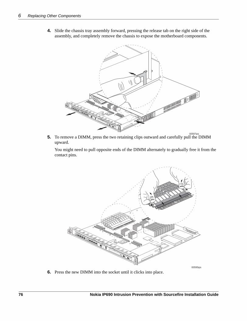
6 Replacing Other Components
4. Slide the chassis tray assembly forward, pressing the release tab on the right side of the assembly, and completely remove the chassis to expose the motherboard components.
5. To remove a DIMM, press the two retaining clips outward and carefully pull the DIMM upward. You might need to pull opposite ends of the DIMM alternately to gradually free it from the contact pins.
6. Press the new DIMM into the socket until it clicks into place.
SLOT 1
SLOT 2
SLOT 3
SLOT 4 IP690
RESET
AUX
CONSOLE
00597ips
LINKACT
V2
LINKACT
1000
Base
T
FailO
pen
1
1
23
AB
4
2
3
4
FailO
pen
1
1
23
AB
4
2
3
4
00595ips
SLOT 1
SLOT 2
SLOT 3
SLOT 4 IP690
RESET
AUX
CONSOLE
LINKACT
V2
LINKACT
1000
Base
T
FailO
pen
1
1
23
AB
4
2
3
4
FailO
pen
1
1
23
AB
4
2
3
4
76 Nokia IP690 Intrusion Prevention with Sourcefire Installation Guide

Replacing or Upgrading Memory
The top of the DIMM is smooth. The bottom edge has two different-length sets of contacts, which mate with the slots on the socket. Be sure the contacts and slots are properly aligned before you insert the DIMM.The retaining clips move into the lock position as you press the DIMM into place.
7. Slide the chassis tray assembly back into the appliance until it clicks into place.
8. Resecure the two chassis tray assembly retaining screws.9. Turn on the power.Nokia IP690 IPS automatically recognizes the new memory configuration. You can verify the configuration by using Nokia Network Voyager or the CLI.
00596ips
SLOT 1
SLOT 2
SLOT 3
SLOT 4
1�2�3�4
IP690
RESET
AUX
CONSOLE
LINKACT
V2
LINKACT
1000
Base
T
FailO
pen
1
1
23
AB
4
2
3
4
FailO
pen
1
1
23
AB
4
2
3
4
SLOT 1
SLOT 2
SLOT 3
SLOT 4 IP690
RESET
AUX
CONSOLE
00583ips
LINKACT
V2
LINKACT
1000
Base
T
FailO
pen
1
1
23
AB
4
2
3
4
FailO
pen
1
1
23
AB
4
2
3
4
Nokia IP690 Intrusion Prevention with Sourcefire Installation Guide 77

6 Replacing Other Components
Replacing a Fan UnitThe appliance fan unit is a single unit made up of four individual fans to provide the air flow required to maintain a proper operating temperature. The fan unit can provide proper airflow for a short time even if an individual fan fails.Before you replace a fan unit, you must first turn off power to the appliance.
Before You BeginTo replace a fan unit, you need:
Physical access to the applianceReplacement fan unit kitA Phillips-head screwdriver
CautionComponents inside the appliance can overheat if they are not cooled even for a short period of time. If you are replacing a failed fan unit, you must completely remove power to the appliance.
To replace a fan unit1. Use Nokia Network Voyager or the command-line interface (CLI) to perform an orderly
shutdown of Nokia IP690 IPS. For information about how to access Network Voyager and the related reference materials, see “Using Nokia Network Voyager” on page 40.
2. Turn off power to the appliance.3. Locate the fan unit on the back of the appliance and the two retaining screws that secure it.
4. Loosen the retaining screws by turning them counterclockwise.
00580ips
FAULT
OVER TEMPOVER�
PWER OK
Retaining screws
78 Nokia IP690 Intrusion Prevention with Sourcefire Installation Guide

Replacing or Installing a Power Supply
5. Slowly pull the fan unit out of the chassis toward the rear.
6. Insert the new fan unit into the chassis.7. Tighten the two retaining screws on the new fan unit.8. Turn on the power.
Replacing or Installing a Power SupplyThe appliance supports redundant 250-watt power supplies. The power supplies are autosensing and can accept input voltages between 47Hz-64Hz and 85VAC-264VAC. The power supply output is regulated to a tolerance of ± 5 percent of the specified output voltage.
Before You BeginTo install or replace a power supply, you need:
Physical access to the applianceA replacement power supply
Figure 25 shows an appliance with two power supplies installed. If you have only one power supply installed, the empty bay will have a filler panel.
Figure 25 Power Supply Locations
00587ips
00580
FAULT
OVER TEMPOVER�
PWER OK
FAULT
OVER TEMPOVER�
PWER OK
Power supplies
Nokia IP690 Intrusion Prevention with Sourcefire Installation Guide 79

6 Replacing Other Components
CautionYou should have working knowledge of networking equipment before you attempt to service an appliance. Limit service to the procedures described in this document.
CautionProtect your appliance and other electronic equipment from electrostatic discharge damage by making sure you are properly grounded before you touch any component.
To replace or install a power supply1. Use Nokia Network Voyager or command-line interface (CLI) to perform an orderly
shutdown of the IP690 IPS appliance. For information about how to access Network Voyager, see Using Nokia Network Voyager on page 40.
2. Locate the power supply on the back of the appliance.3. Turn off the power to the power supply.4. Remove the power cord.5. Remove the grounding cable if one is in use.6. To remove a power supply, grasp the handle and release lever as shown in the following
figure, and use the handle to gently pull the power supply out of the chassis.
If you are installing a second power supply, remove the filler panel from the power supply bay.
00588
80 Nokia IP690 Intrusion Prevention with Sourcefire Installation Guide

Replacing the Battery
7. Insert the new power supply into the empty bay until the release lever latches.
8. Attach the grounding cable if being used.9. Turn on the power.
Replacing the BatteryTo replace the battery, you need the following:
The appropriate Nokia battery replacement kit for your appliancePhysical access to the applianceA Phillips-head screwdriverA grounding wrist strap(Optional) Safety glasses
WarningRisk of explosion if battery is replaced by an incorrect type. Replace the battery only with the same or equivalent type that the manufacturer recommends. Dispose of used batteries according to the manufacturer's instructions.
CautionMake certain that you are properly grounded when you handle components internal to the appliance to protect against electrostatic discharge damage to the appliance. Use the grounding strap included in the battery replacement kit.
To install the battery, perform the following tasks:1. Use Nokia Network Voyager or the command-line interface (CLI) to perform an orderly
shutdown of the appliance. For information about how to access Network Voyager and the related reference materials, see “Using Nokia Network Voyager” on page 40.
2. Turn off the power to the appliance.
00598
Nokia IP690 Intrusion Prevention with Sourcefire Installation Guide 81

6 Replacing Other Components
3. Loosen the front panel retaining screws.4. Slide the chassis tray assembly forward, pressing the release tab on the right side of the
assembly, and completely remove the chassis to expose the motherboard components.
5. Place the chassis tray assembly on a table top.6. Locate the battery on the motherboard.
SLOT 1
SLOT 2
SLOT 3
SLOT 4 IP690
RESET
AUX
CONSOLE
00597ips
LINKACT
V2
LINKACT
1000
Base
T
FailO
pen
1
1
23
AB
4
2
3
4
FailO
pen
1
1
23
AB
4
2
3
4
82 Nokia IP690 Intrusion Prevention with Sourcefire Installation Guide

Replacing the Battery
The battery is in a black battery holder secured with a battery retaining pin.
7. Remove the old battery. Use a small nonconductive device, such as a plastic probe, to slide the battery out of the battery holder through the cutout in the holder. To properly dispose of the battery, see “Related Documentation” on page 16.
8. With the positive side facing up, slide the new battery through the cutout in the battery holder.
CautionYou must place the new battery into the battery holder observing the correct polarity. The positive terminal of the battery must be facing up.
00594ips
SLOT 1
SLOT 2
SLOT 3
SLOT 4 IP690
RESET
AUX
CONSOLE
LINKACT
V2
LINKACT
1000
Base
T
FailO
pen
1
1
23
AB
4
2
3
4
FailO
pen
1
1
23
AB
4
2
3
4
Nokia IP690 Intrusion Prevention with Sourcefire Installation Guide 83

6 Replacing Other Components
9. Slide the chassis tray assembly back into the appliance until it clicks into place.
10. Resecure the chassis tray assembly retaining screws.11. Turn on the power supply at the back of the appliance.12. Reset the appliance date and time information by using Nokia Network Voyager or the
command-line interface. The battery is required to maintain the date and time whenever you shut down the appliance.
SLOT 1
SLOT 2
SLOT 3
SLOT 4 IP690
RESET
AUX
CONSOLE
00583ips
LINKACT
V2
LINKACT
1000
Base
T
FailO
pen
1
1
23
AB
4
2
3
4
FailO
pen
1
1
23
AB
4
2
3
4
84 Nokia IP690 Intrusion Prevention with Sourcefire Installation Guide

7 Troubleshooting
This chapter provides troubleshooting tips, problems, and solutions related to Nokia IP690 IPS installations.
Unable to Log in to the Console Port—No Error MessageTwo laptop computers (using terminal emulation programs) or terminals should be able to communicate back to back in the same way that the terminal communicates with Nokia IP690 IPS. If this is not possible using your laptop computer or terminal, the problem is with the terminal or cable and not the appliance.
Problem You do not have a console connection to the appliance.Solution For information about how to create a console connection, see “Using a Console Connection” on page 39.
Problem Not connected with a null-modem cable. Solution Verify that you are using a null-modem cable. For pinout information, see “Using a Console Connection” on page 39.
Problem Wrong terminal settings.Solution Verify terminal settings: 8 data, 1 stop, no parity, 9600 bps.
Problem Terminal set for flow control.Solution Nokia IP690 IPS does not use flow control. The terminal should be set for no flow control.
Problem Defective Nokia IP690 IPS or file system.Solution Contact the Nokia customer support site listed in “Nokia Contact Information” on page 3.
Nokia IP690 Intrusion Prevention with Sourcefire Installation Guide 85

7 Troubleshooting
Do Not Get a Login Prompt—Error Messages Appear
Problem The appliance is defective, or the file system on the appliance is defective.Solution Contact the Nokia customer support site listed in “Nokia Contact Information” on page 3.
NoteUse the full installation procedure to install a new system. The new system completely replaces the contents of the drive and might be needed to restore or reload a Nokia IP690 IPS. This procedure erases any configuration database on the appliance. For information about how to complete the full installation procedure, see the current release notes. The release notes are located on the Nokia customer support Web site as listed in the “Nokia Contact Information” on page 3.
Login Prompt Appears, But Password Not Accepted
Problem Entered wrong password.Solution Obtain a valid password or set the password to a default value.
To reset the Admin password without knowing the current password1. Log in to the system as the root user.2. Open a CLI shell by entering the following command:
su - admin
This operation does not require a password.3. If the default shell for Admin is not clish, enter the clish command.4. Enter the following command:
set user admin passwd
5. At the prompt Old password, press Enter without typing a password.6. At the New password and Verify new password prompts, enter the new password and
press Enter.The password is now reset.
If you have lost the root password, you can reset the root password by using the procedure in “To reset the password for root user.” You must have physical access to the device to perform this procedure.
86 Nokia IP690 Intrusion Prevention with Sourcefire Installation Guide

To reset the password for root user1. From a console connection, reboot the system, watching the message that appear on the
console.2. Enter the boot manager by typing 2 when you see the following message:
LILO 22.5.91 ipso2 bootmgrPress key '2' to enter BOOTMGR command modeboot:
You must do this within 5 seconds or else the reboot continues.3. When you see the BOOTMGR[1]> prompt, enter the following command:
overpw
This is a hidden command and is not in the help menu. The root password is reset to " ", that is, there is no password.
4. Continue the boot process by entering the following command:boot
5. Log in as root (no password)6. Enter the following command:
passwd root 7. Set a new password for root.
Unable to Connect to Network Voyager Using the Ethernet Port, But Console Access Works
Problem Using the wrong Ethernet cable.Solution Use a crossover Ethernet cable if you are connecting directly to the computer. Use a straight-through cable if you are connecting to a hub. For cabling information, see “Connecting to Network Interfaces” on page 36.
Problem Port is not configured as active. Solution Use the CLI over the console connection to verify the interface configuration and fix it if necessary.
Problem Host port configuration is incorrect.Solution Use the CLI over the console connection to verify the interface configuration and fix it if necessary.
Nokia IP690 Intrusion Prevention with Sourcefire Installation Guide 87

7 Troubleshooting
Problem Wrong link speed.Solution Use the CLI over the console connection to verify the interface configuration and fix it if necessary.
Do Not See Interfaces that Should be Present
Problem Local appliance ports do not appear. Solution Your NIC might be defective. Contact the appropriate Nokia customer support site as listed in “Nokia Contact Information” on page 3.
NoteThe problem could be with the slot on the PMC card carrier. Try installing the NIC in another slot.
Common Ethernet Problems—Connectivity with Attached Device
Problem No link light. Solution You might have used the wrong cable. Use a crossover cable between a Nokia IP690 IPS and a host, and a straight-through cable between an appliance and a hub.
Problem Solid data and activity LED. Solution You might have set the wrong speed. Verify that the speeds match on each end of the Ethernet connection.
Problem Port not enabled.Solution Verify from the Interface page in Network Voyager that the interface port is configured as active.
Problem High collision rate on the hub. Solution Disconnect connections one at a time until the problem is localized to one computer and troubleshoot further.
Unable to Ping Through Appliance—No Connectivity Between Ports This section covers connectivity issues that are isolated within an Nokia IP690 IPS or network.Localize the problem by issuing pings to various network interfaces. Use tcpdump to help isolate the problem. Use tcpdump to verify that a packet is leaving or entering a port.
Problem Interfaces not up. Solution Ensure that the interfaces are up and active, as described in Chapter 3, “Performing the Initial Configuration.”
88 Nokia IP690 Intrusion Prevention with Sourcefire Installation Guide

Problem No route to network. Solution Check the routing table to see if a route exists to the network where the interface is located.
Problem Attached device does not have proper default route or routing information. Solution If a local computer is unable to ping through an attached appliance, the computer might contain either an invalid default route or invalid routing information.If you are using default routes from a computer, ensure that the local interface is the default route for that computer.
Appliance Not Receiving Power
Problem Power cord is not properly plugged in.Solution Check cord. Make sure it is properly seated at both ends.
Problem Power supply not providing power.Solution Check power source. If there is no power at the source, take appropriate action such as inserting a new fuse or resetting circuit breaker.
Appliance Does Not Recognize New Memory Configuration
Problem DIMMs are not properly seated in DIMM sockets.Solution Repeat memory installation procedures. Make sure DIMMs are fully seated in sockets. Be sure DIMMs click into place.
Nokia IP690 Intrusion Prevention with Sourcefire Installation Guide 89

7 Troubleshooting
90 Nokia IP690 Intrusion Prevention with Sourcefire Installation Guide

A Technical Specifications
Physical Dimensions
Space RequirementsNokia IP690 IPS is designed for front-screw mounting in a standard 19-inch rack. Each Nokia IP690 IPS requires the following space in a rack:
3.5 inches (8.9 centimeters) of vertical space 2.0 inches (15.0 centimeters) behind and to the sides of the appliance to allow the exit fans to move air through the appliances
CautionDo not block the ventilation holes on Nokia IP690 IPS. The appliance might overheat and become damaged.
Dimensions Height: 1.7 in. (43.4 cm)
Width: 17 in. (43.2 cm, without mounting bracket)19 in. (48.3 cm, with mounting bracket)
Depth: 24.9 in. (63.2 cm) including front bezel 25.4 in. (64.5 cm) including front handles
Weight 12.4 kg (27.3 lbs)
Nokia IP690 Intrusion Prevention with Sourcefire Installation Guide 91

A Technical Specifications
Other Specifications
Operational Temperature 41 to 104° Fahrenheit5 to 40° Celsius
Humidity Humidity 5% to 85%
Maximum altitude of operation To 10, 000 feet or 3300 meters above sea level
Input voltage requirement 100 VAC or 240 VAC, 50 or 60 Hz
Current 4A
Power consumption 250 watts per power supply
92 Nokia IP690 Intrusion Prevention with Sourcefire Installation Guide

B Compliance Information
This appendix contains the following compliance information:Declaration of ConformityCompliance StatementsFCC Notice (US)
Declaration of ConformityAccording to ISO/IEC Guide 22 and EN 45014:
declares that the product:
conforms to the following standards:
Manufacturer’s Name: Nokia, Inc.
Manufacturer’s Address: 313 Fairchild DriveMountain View, CA 94043-2215USA
Product Name: IP690 and IP690 IPS
Model Number: EM7900
Product Options: All
Serial Number: 1 to 100,000
Date First Applied: 2006
Safety: UL60950-1, First Edition:2003, CAN/CSA-C22.2 No 60950:2000, IEC60950-1: 2001, EN60950-1:2001+A11 with Japanese National Deviations
EMC: EN55024 1998, EN55022A 1998, EN61000-3-2, EN61000-3-3
Nokia IP690 Intrusion Prevention with Sourcefire Installation Guide 93

B Compliance Information
Supplementary information:Pursuant to directive 1999/5/EC this product complies with the requirements of the Low Voltage Directive 73/23/EEC and the EMC Directive 89/336/EEC with Amendment 93/68/EEC.
Compliance StatementsThis hardware complies with the standards listed in this section.
Emissions Standards
Immunity Standards
Harmonics and Voltage Fluctuation
Christopher SaleemCompliance & Reliability Engineering ManagerSecurity & Mobile Connectivity, Enterprise SolutionsMountain View, CaliforniaMay 2007
FCC Part 15 Subpart B Class A US/Canada
EN55022 (CISPR 22 Class A) European Community (CE)
EN55024 European Community (CE)
EN61000-4-2 European Community (CE)
EN61000-4-3 European Community (CE)
EN61000-4-4 European Community (CE)
EN61000-4-5 European Community (CE)
EN61000-4-6 European Community (CE)
EN61000-4-11 European Community (CE)
EN61000-3-2 European Community (CE)
EN61000-3-3 European Community (CE)
94 Nokia IP690 Intrusion Prevention with Sourcefire Installation Guide

FCC Notice (US)
Safety Standards
FCC Notice (US)This device has been tested and found to comply with the limits for a Class A digital device, pursuant to Part 15 of the FCC Rules. These limits are designed to provide reasonable protection against harmful interference in a residential installation. This device generates, uses, and can radiate radio frequency energy and, if not installed and used in accordance with the instruction, may cause harmful interference to radio communications. However, there is no guarantee that interference will not occur in a particular installation. If this device does cause harmful interference to radio or television reception, the user is encouraged to try to correct the interference by one or more of the following measures:
Reorient or relocate the receiving antenna.Increase the separation between the computer and receiver.Connect the computer into an outlet on a circuit different from that to which the receiver is connected.Consult the dealer or an experienced radio/TV technician for help.
CautionAny changes or modifications not expressly approved by the grantee of this device could void the user’s authority to operate the equipment.
050316
UL60950/EN60950 US/European Community(CE)
CAN/CSA-C22.2 No.60950 Canada
Nokia IP690 Intrusion Prevention with Sourcefire Installation Guide 95

B Compliance Information
96 Nokia IP690 Intrusion Prevention with Sourcefire Installation Guide

Index
AAC power receptacle 25appliance
configuring 39management 26overview 20rack-mounting 30
autosensing of voltages 25auxiliary port 23
Bbattery
holder 83location 83replacing 81
blinking green LED 24blinking yellow LED 24blue LED 24
Ccables
Gigabit Ethernet NIC connectionsfor copper 46for copper fail open 51for fiber optic 48for fiber optic fail open 54
RJ-45 null-modem for console 34caution notices 14command-line interface (CLI)
using the 42compact flash card 65compliance information 93compliance statements 94component locations 20connections
copper Gigabit Ethernet NIC 46fiber-optic Gigabit Ethernet NIC 48modem 23power 36
console cable 35pin assignments 22
console port 22supplied cable for 34terminal settings 34
copper Gigabit Ethernet NIC 44, 46, 49
DDB-9 terminal adapter 22deactivating, network interface cards 57depth 91dimensions 91DIMMs 73
adding or replacing 75dual-port Ethernet network interface card 48
EEMC standards 93emissions standards 94end-of-life information 28Ethernet ports 20, 21expansion slots 21
FFail open NIC
bypass state 49, 53how it works 49, 53normal state 49, 53
fan unitlocation 25overview 26replacing 78
fiber-optic Gigabit Ethernet NICs 48four-port copper Gigabit Ethernet NIC 44four-port fail open copper Gigabit Ethernet NIC 49front panel 20
GGigabit Ethernet NICs
four-port copperconnecting to 46front panel 45
four-port copper fail openconnecting to 51front panel 50
two-port copperconnecting to 46front panel 45
two-port copper fail openconnecting to 51
Nokia IP690 Intrusion Prevention with Sourcefire Installation Guide Index - 97

front panel 50two-port fiber-optic
connecting to 48front panel 48
two-port fiber-optic fail openconnecting to 54front panel 54
green LED 25grounding cable 80
HHAR cordage, power cord 27hard-disk drive
installing 69location 71replacing 69
harmonics 94height 91host terminal 23
IIEC fittings, power cord 27IEEE 802.3ab 21, 44IEEE 802.3z 47immunity standards 94input voltage 25installing NICs 58IPSO-LX
command-line interface (CLI) 26, 42reference documentation 41
LLC connector 48LEDs
Gigabit Ethernet NICsfour-port copper 45four-port copper fail open 50two-port copper 45two-port copper fail open 50two-port fiber-optic 48two-port fiber-optic fail open 54
Normal on fail open NICs 51, 54power supply 25system status 23
Mmanaging the appliance 26memory, replacing or upgrading 73
monitoring 23NICs 63
mounting brackets 33multi-mode, fiber-optic cable 48
Nnetwork interface cards
deactivating 57dual-port Ethernet 48four-port copper Gigabit Ethernet 45four-port fail open copper Gigabit Ethernet 49installing 57, 58list of available 43monitoring 63PCI operation 43two-port copper Gigabit Ethernet 44two-port fail open copper Gigabit Ethernet 49two-port fail open fiber-optic Gigabit Ethernet 53two-port fiber-optic Gigabit Ethernet 47
Nokia IPSO-LXcommand-line interface (CLI) 26, 42reference documentation 41
Nokia Network Voyager 26opening 40using 40
null-modem cable 35
Ooperating system requirements 27operational temperature 92output connector
Gigabit Ethernet NIC, copper 46Gigabit Ethernet NIC, copper fail open 52Gigabit Ethernet NIC, fiber-optic 48Gigabit Ethernet NIC, fiber-optic fail open 54
PPCI operation of NICs 43physical dimensions 91pin assignments
console connection 22modem connection 22
PMC expansion slots 57power connections 36power cord rating 27power supply 25
location 25replacing 79status LEDs 25
Index - 98 Nokia IP690 Intrusion Prevention with Sourcefire Installation Guide

product disposal 28
Rrack-mounting 30recycling retired equipment 28red LED 24, 25release tab 67RJ-45
connector 22
Ssafety standards 93serial port 23site requirements 27software requirements 27space requirements 91specifications, technical 91system status LEDs 23
Ttechnical specifications 91temperature 92troubleshooting 85
Uupgrading memory 73
Vventilation requirements 91vertical space requirements 91voltage 25voltage fluctuation 94
Wwarning notices 14weight 91width 91
Yyellow LED 24, 25
Nokia IP690 Intrusion Prevention with Sourcefire Installation Guide Index - 99

Index - 100 Nokia IP690 Intrusion Prevention with Sourcefire Installation Guide


