150307 rev. D 1/11/2012 LH Series Sensor Configurator ...
47
LH Series Sensor Configurator Software User Manual 150307 rev. D 1/11/2012
Transcript of 150307 rev. D 1/11/2012 LH Series Sensor Configurator ...
LH Series Sensor Configurator Software User Manual150307 rev. D 1/11/2012

ContentsLH Series Sensor Overview .....................................................................................................................3
Theory of Operation .............................................................................................................................................................4Outputs ................................................................................................................................................................................4
4-20mA Analog Output ...............................................................................................................................................4RS-485 Digital Output .................................................................................................................................................5
Performance Specifications .................................................................................................................................................5Factory Defaults ...................................................................................................................................................................6
LH Series Configurator Overview ............................................................................................................7LH Series Configurator Main Screen ...................................................................................................................................7
Setting Up an LH Network ........................................................................................................................9Building a Basic LH Network .............................................................................................................................................10
Network Setup of a Thickness Master/Slave Pair of Sensors ...................................................................................11Building a Network of Sensors ..............................................................................................................13
Adding Displacement Sensor(s) to an LH Network ...........................................................................................................13Adding Thickness Master/Slave Pair(s) of Sensors to an LH Network ..............................................................................15
LH Assistant Common Screens .............................................................................................................18LH Assistant - Confirm Sensor ..........................................................................................................................................18LH Network Setup ..............................................................................................................................................................18
Utility Tools ..............................................................................................................................................20Resetting a Single Sensor Back to Factory Defaults .........................................................................................................20Manually Assign a Single Sensor ......................................................................................................................................20
Sensor Configuration .............................................................................................................................21Measurements Configuration .............................................................................................................................................21
Displacement: Single Point TEACH ..........................................................................................................................23Displacement: Two Point TEACH .............................................................................................................................24Thickness Delta: Single Point TEACH ......................................................................................................................26Thickness Delta: Two Point TEACH .........................................................................................................................27
Advanced Configuration ....................................................................................................................................................29Thickness Delta Offset .......................................................................................................................................................31Analog Output Offset .........................................................................................................................................................33Thickness Delta Alignment Tool .......................................................................................................................................34
LH Network and Measurements .............................................................................................................36LH Network Tab .................................................................................................................................................................36Measurements Tab ............................................................................................................................................................37Sampling Setup .................................................................................................................................................................39
LH Series Serial Communication ...........................................................................................................41LH Network Protocol ..........................................................................................................................................................41
Error Codes .............................................................................................................................................43Warnings ............................................................................................................................................................................44Finding and Fixing Faults ...................................................................................................................................................47
Contents
2 150307 rev. D

LH Series Sensor Overview
Banner's LH Series Laser Displacement Sensor brings a sophisticated and cost-effective solution to precision measurement applications.Featuring a narrow effective beam, excellent resolution, and user configurable outputs, the LH Series sensor solves a variety of measure-ment applications with an all-in-one design. The LH Series Sensor can serve as a displacement measurement sensor or can performthickness delta measurements when two sensors are configured to work together. The LH Series Configurator is a software tool for con-figuring the sensor and acquiring measurements using serial communication over RS-485. Measurements can be acquired from multiplesensors networked together using the LH Network protocol.
WARNING: Not To Be Used for Personnel Protection
Never use this product as a sensing device for personnel protection. Doing so could lead to seri-ous injury or death. This product does NOT include the self-checking redundant circuitry necessary toallow its use in personnel safety applications. A sensor failure or malfunction can cause either an ener-gized or de-energized sensor output condition.
WARNING: Class 2 Safety Notes
Low-power lasers are by definition incapable of causing eye injury within the duration of the blink, or aver-sion response of 0.25 seconds. They must also emit only visible wavelengths (400-700 nm). Therefore, anocular hazard can only exist if an individual overcomes their natural aversion to bright light and staresdirectly into the laser beam. The product requirements for these lasers are to have a [hazard] label and tohave an indicator light to indicate laser emission.
The two operational safety rules are:• Do not permit a person to stare at the laser from within the beam• Do not point the laser at a person's eye at close range
WARNING: Beam Paths:
The beam emitted by a class 2 laser product should be terminated at the end of its useful path. Open laserbeam paths should be located above or below eye level where practical.
150307 rev. D www.bannerengineering.com - tel: 763-544-3164 3

Theory of OperationThe design of the LH Series Laser Displacement Sensor is based on optical triangulation. An emitter transmits visible laser light througha lens, towards a target. The laser light is reflected diffusely from the surface of the target. A second (receiver) lens on the sensor thenfocuses that reflected light, creating a spot of light on a CMOS linear imager.
Figure 1. Optical Triangulation Sensing System Overview
The target’s distance from the sensor determines the angle the light travels through the receiver lens; this angle in turn determines wherethe received light will fall along the CMOS linear imager.
The position of the light on the CMOS linear imager is processed through analog and digital electronics and analyzed by the digital signalprocessor (DSP), which determines the distance to the current target relative to the start of the measurement range. This distance meas-urement is available on the 4-20mA analog output and the RS-485 digital output.
Outputs4-20mA Analog OutputThe LH Series sensor's 4-20mA analog output can be easily scaled over the sensing application's measurement window (this windowmust be contained within the sensor's start/end of measurement range). The analog output is precisely calibrated over the range of4-20mA. Measurement readings outside of this range are considered invalid and should not be used. The LH Series Configurator can beused to TEACH and/or manually adjust the near/far limits of the measurement window. Displacement measurement applications can beconfigured to have a positive or negative slope on the analog output. Thickness delta measurement applications require a positive slopeon the analog output. Factory defaults for the analog output are a full scale measurement window with a positive slope (i.e. 4mA at thestart of measurement range and 20mA at the end of measurement range). As soon as the target moves out of the measurement range,the most recent valid measurement is retained for 5 measurement periods (1.25ms). At the end of this time, the analog output current
LH Series Sensor Configurator Software User Manual
4 www.bannerengineering.com - tel: 763-544-3164 150307 rev. D

reverts to its inactive value of 2mA. When a new target enters the measurement range, after 1 measurement period (0.25ms), the newmeasurement value will become available on the analog output.
RS-485 Digital OutputThe LH Series sensor's RS-485 digital output provides a 16-bit value representing the measurement. The digital output is precisely cali-brated over the range of 2768-62768. Measurement readings outside of this range are considered invalid and should not be used. Thedigital output limits cannot be adjusted, they are always scaled over the entire measurement range. Displacement measurements have anegative slope on the digital output (i.e. 62768 at the start of measurement range and 2768 at the end of measurement range). Thicknessdelta measurements have a positive slope on the digital output (i.e. 2768 at the start of measurement range and 62768 at the end ofmeasurement range). As soon as the target moves out of the measurement range, the digital output provides a value of 65534. When anew target enters the measurement range, after 1 measurement period (0.25ms), the new measurement value will become available onthe digital output. See LH Series Serial Communication on page 41 for more details on using the RS-485 digital output.
Performance Specifications
SpecificationModel
LH30IX485QP LH80IX485QP LH150IX485QP
Measurement Range (mm) 25 to 35 60 to 100 100 to 200
Measurement Span (mm) 10 40 100
Start of Measurement Range (mm) 25 60 100
Reference Distance (mm) 30 80 150
End of Measurement Range (mm) 35 100 200
Maximum Thickness Delta Measure-ment (mm)1
10 40 100
Default Ideal Separation for ThicknessDelta Measurement (mm)
65 180 350
Spot Diameter at Reference Distance(micron)
50 125 225
Linearity2 (0.1% of full scale range)(micron)
10 40 100
Resolution2, 3 (micron) 1 4 10
LH Series Sensor Configurator Software User Manual
150307 rev. D www.bannerengineering.com - tel: 763-544-3164 5

1. Thickness Delta is the change in thickness (i.e. 100-110mm is 10mm of thickness delta)2. Measured at 20°C, using a standard white ceramic target3. Resolution measured with the Output Filter value set to 64
Factory DefaultsThe following are LH Series sensor factory defaults:
Measurement Mode Displacement
Network Address Unset (Address 0)
Baudrate 115200 bps
Analog Output 4-20mA, positive slope, full scale range
Power Mode Auto
Output Filter OFF
LH Series Sensor Configurator Software User Manual
6 www.bannerengineering.com - tel: 763-544-3164 150307 rev. D

LH Series Configurator Overview
The LH Series Configurator is a software tool that is compatible with Windows XP, Windows Vista, and Windows 7 (32-bit and 64-bit).The software can be used to:
• Set up a simple LH network consisting of a single displacement sensor or a sensor pair for a thickness delta measurement• Set up a more complex LH network with more than one sensor• Configure and manage all the sensors in an LH network• Acquire measurement data from all sensors in an LH network
LH Series Configurator Main Screen
1
2
3
4
1. Menu Bar
MainMenu
Menu Option Description
File Return to MainScreen
Returns the user to the Main Screen.
Load Last LH Net-work Setup
The LH Series Configurator software is automatically sav-ing the network setup in the background while the user issetting up the LH Network. This menu option provides away for a user to quickly load the saved network setup af-
150307 rev. D www.bannerengineering.com - tel: 763-544-3164 7

MainMenu
Menu Option Description
ter an interruption. Note that, if something has changed onthe network since the last time the LH Series Configuratorsoftware was used, you will need to re-scan the network.
Open LH NetworkSetup File
Provides a way to load a previously saved LH NetworkSetup File. Note that, if something has changed on thenetwork since the last time the LH Series Configuratorsoftware was used, you will need to re-scan the network.
Save LH Network Set-up File
Saves an LH Network Setup File.
Exit Used to exit the LH Series Configurator software.
Tools LH Assistant An alternative way to access the LH Assistant setup wiz-ards and utility tools.
Show Comm Traffic Used for monitoring communications traffic.
Help Show Help Launches the Main Help contents.
About Banner LH Ser-ies Configurator
Displays software version information.
2. LH AssistantThe LH Assistant button launches the LH Assistant, which includes wizards to guide the user step-by-step through set-ting up a single displacement sensor, a master/slave pair of sensors for a thickness delta measurement, or a network ofsensors. The LH Assistant also includes two utilities, one for resetting a sensor back to factory defaults and the other formanually assigning a sensor to an existing network.
3. LH ConfiguratorThe LH Configurator button connects to the LH Network and launches the LH Network and Measurements screen. Typi-cally, a user will launch the LH Network and Measurements screen after a network is configured for the purpose ofacquiring measurement data from the network, refining sensor configurations, and diagnosing problems.
4. COM PortThe COM Port selector displays the current COM Port that the PC is using to communicate with the LH Network. Thereis an option to Refresh (that is, scan) for all available COM Ports on the PC.
Tip: If using an INTUSB485-LH converter:
1. Refresh the COM Port list with the converter disconnected.2. Connect the converter to an available USB port.3. Refresh the COM Port list again. The converter will be the new COM Port in the list.
LH Series Sensor Configurator Software User Manual
8 www.bannerengineering.com - tel: 763-544-3164 150307 rev. D

Setting Up an LH Network
The LH Assistant is used to start the process of setting up one or more sensor(s) in an LH Network. There are four setup wizards:Single Displacement Sensor
Creates a simple network of one displacement sensor.Thickness Master/Slave Pair of Sensors
Creates a network of a pair of sensors to be used for a thickness delta measurement application.LH Network of Displacement Sensors
Creates a new network of displacement sensors. Networking sensors together enables a single management point for con-figuring and monitoring sensors.
Add Displacement SensorsAdds one or more sensors to an existing LH Network.
Additionally, there are two utility tools that require a direct connection to a single sensor removed from the LH Network:Reset a Single Sensor
Resets a single sensor back to factory defaults.Manually Assign a Single Sensor
Manually assigns a single sensor's address and/or baudrate.
LH Assistant Screen
150307 rev. D www.bannerengineering.com - tel: 763-544-3164 9

Building a Basic LH NetworkA basic LH Network setup is comprised of either:
• One sensor configured for a Displacement measurement• Master/Slave pair of sensors configured for a Thickness Delta measurement
Network Setup of a Single Displacement SensorThe LH Assistant wizard will guide you through initializing a single LH Series sensor that will be configured for displacement measure-ment mode. After completing this procedure using the wizard to guide you, the LH Series sensor will be the only sensor on the LH Net-work and will be automatically assigned Address #1.
1 Connect to an LH-Series sensor.
2 Connect to a INTUSB485-LH adapt-er, which is properly connected to aUSB drive on the PC.
3 Connect to cordset MQLH-806-F orsimilar. See table below for hookup.
Cable splitter CSB-M1281M1282-LH allows convenient connection of a single sensor to the INTUSB485-LH adapter, power supply, andanalog input card. Cable splitter CSB3-M1281M1282-LH is recommended for thickness delta measurement applications.
Pin Color Description
18-30V dc–
+2
7
–
+14-20 mA
3
5
6
4
8Shield/Drain
Wire*
RS-485 GND
RS-485 RX+/TX+
RS-485 RX-/TX-
1 White 4-20 mA output source
2 Brown Power supply 18-30V dc
3 Shield (bundled withwhite wire inside blue foilwrap)
4-20 mA output return
4 Yellow RS-485 RX- / TX-
5 Grey Ground of RS-485 bus
6 Green RS-485 RX+ / TX+
7 Blue Ground
8 Shield Shield/drain wire*
* The shield/drain wire is connected internally to the sensor housing and should be connected as follows:
1. If the sensor housing is mounted so that it is in continuity with both the machine frame and earth ground, connect the shield/drainwire (also) to earth ground.
2. If the sensor housing is mounted so that it is insulated from the machine frame, connect the shield/drain wire to -V dc (together withthe blue wire).
3. If the sensor is mounted so that it is in continuity with the machine frame, but not with earth ground, do not connect the shield/drainwire (i.e. cut off the shield/drain wire).
LH Series Sensor Configurator Software User Manual
10 www.bannerengineering.com - tel: 763-544-3164 150307 rev. D

NOTE: The green LED on the sensor should be lit.
Use the wizard to guide you through adding the sensor to the network. When the software displays the LH Network Status screen, youcan select one of the following:
• Click Finish to exit the wizard.• Click Configure Sensor to launch the Sensor Configuration window.• Click Network Setup to launch the Network Setup window, which can be used to enable the Network Output Timer or to view/modify
network settings.• Click Scan Network to re-scan the LH Network.
Network Setup of a Thickness Master/Slave Pair of SensorsWhen setting up a thickness master/slave pair of sensors, it is important to note that the slave automatically sends its displacementmeasurement to the master over the RS-485 bus. The master then calculates the thickness delta measurement using the slave's meas-urement and its own measurement.
Before beginning to set up a thickness master/slave pair of sensors, there are a couple things you need to know:• Make sure that both sensors to be added are unset (address 0). If either of the sensors has been previously set up (or if you are
unsure of the sensor status), use the Reset a Single Sensor utility to reset the sensor(s) back to factory defaults.• Both sensors must be the same model (for example, both sensors must be LH30s or both LH80s, etc).• To start, only the slave sensor must be connected and powered; the master will be connected after the LH Assistant discovers and
initializes the slave.• If using a Banner three-way splitter (model CSB3-M1281M1282-LH), the INTUSB485-LH converter must be connected to connector
#3 on the splitter; the slave must be connected to connector #2. Once the slave has been discovered and initialized, you will need toconnect the master to connector #1 so its analog output is available.
Use the wizard to guide you through adding each sensor to the network. When done, the slave will be assigned address #1, and themaster will be assigned address #2. Additionally, the Network Output Timer will be enabled and set to the minimum value (for example, 1
LH Series Sensor Configurator Software User Manual
150307 rev. D www.bannerengineering.com - tel: 763-544-3164 11

ms when using the default 115200 baudrate). The Network Output Timer must be enabled for a thickness delta measurement. Is themechanism that allows the slave sensor to automatically send its displacement measurement to the master sensor.
NOTE: Once a slave is assigned to a master through the wizard, the master and slave are paired and theslave cannot be paired with any other master.
When the software displays the LH Network Status screen, you can choose one of the following:• Click Finish to exit the wizard.• Click Configure Sensor for the master to launch the Sensor Configuration window.• Click Network Setup to launch the Network Setup window, which can be used to modify the Network Output Timer or to view /modify
network settings.• Click Scan Network to re-scan the LH Network
LH Network with a Master/Slave Sensor Pair
LH Series Sensor Configurator Software User Manual
12 www.bannerengineering.com - tel: 763-544-3164 150307 rev. D
Building a Network of Sensors
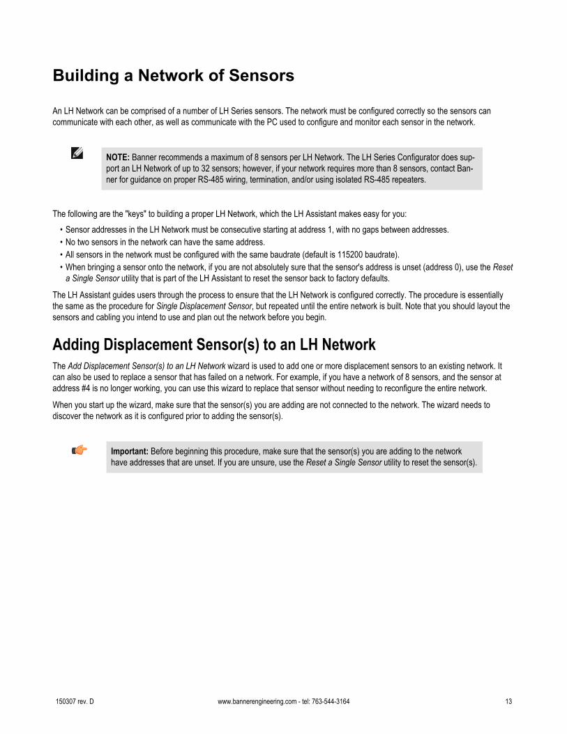
An LH Network can be comprised of a number of LH Series sensors. The network must be configured correctly so the sensors cancommunicate with each other, as well as communicate with the PC used to configure and monitor each sensor in the network.
NOTE: Banner recommends a maximum of 8 sensors per LH Network. The LH Series Configurator does sup-port an LH Network of up to 32 sensors; however, if your network requires more than 8 sensors, contact Ban-ner for guidance on proper RS-485 wiring, termination, and/or using isolated RS-485 repeaters.
The following are the "keys" to building a proper LH Network, which the LH Assistant makes easy for you:• Sensor addresses in the LH Network must be consecutive starting at address 1, with no gaps between addresses.• No two sensors in the network can have the same address.• All sensors in the network must be configured with the same baudrate (default is 115200 baudrate).• When bringing a sensor onto the network, if you are not absolutely sure that the sensor's address is unset (address 0), use the Reset
a Single Sensor utility that is part of the LH Assistant to reset the sensor back to factory defaults.
The LH Assistant guides users through the process to ensure that the LH Network is configured correctly. The procedure is essentiallythe same as the procedure for Single Displacement Sensor, but repeated until the entire network is built. Note that you should layout thesensors and cabling you intend to use and plan out the network before you begin.
Adding Displacement Sensor(s) to an LH NetworkThe Add Displacement Sensor(s) to an LH Network wizard is used to add one or more displacement sensors to an existing network. Itcan also be used to replace a sensor that has failed on a network. For example, if you have a network of 8 sensors, and the sensor ataddress #4 is no longer working, you can use this wizard to replace that sensor without needing to reconfigure the entire network.
When you start up the wizard, make sure that the sensor(s) you are adding are not connected to the network. The wizard needs todiscover the network as it is configured prior to adding the sensor(s).
Important: Before beginning this procedure, make sure that the sensor(s) you are adding to the networkhave addresses that are unset. If you are unsure, use the Reset a Single Sensor utility to reset the sensor(s).
150307 rev. D www.bannerengineering.com - tel: 763-544-3164 13

1. Discover the current network.
2. Click the Add button to add the new sensor. The wizard will guide you through connecting the sensor to the network.
The dialog shows how the new sensor will be added to the network. It will try to fill any holes in the network. In this case, address#4 is open, so it will add the new sensor at address #4.
3. Click the Yes button.
LH Series Sensor Configurator Software User Manual
14 www.bannerengineering.com - tel: 763-544-3164 150307 rev. D

Adding Thickness Master/Slave Pair(s) of Sensors to an LH NetworkThe Thickness Master/Slave Pair of Sensors wizard will setup a network of two sensors to perform a thickness delta measurement. Addi-tional thickness master/slave pairs of sensors can be added to the network with the Add Displacement Sensor(s) to an LH Networkwizard and then using the Sensor Configuration window to configure the master sensors for thickness delta measurement mode.
To setup an LH Network with multiple thickness master/slave pairs of sensors:
LH Series Sensor Configurator Software User Manual
150307 rev. D www.bannerengineering.com - tel: 763-544-3164 15

1. Use the Thickness Master/Slave Pair of Sensors wizard to setup the first pair of sensors.
2. Add the remaining sensors one at a time to the network with the Add Displacement Sensor(s) to an LH Network wizard.
3. Launch the Sensor Configuration window for each sensor that you want to configure as a Thickness Master. This can be done by
clicking on the green Configure Sensor cells in the LH Network Status table.
LH Series Sensor Configurator Software User Manual
16 www.bannerengineering.com - tel: 763-544-3164 150307 rev. D

4. Configure each Thickness Master sensor for Thickness Delta Measurement Mode, and select the matching Slave sensor from the
Thickness Slave selection list. Write the configuration to the Master sensor by clicking the Write to Sensor button.
LH Series Sensor Configurator Software User Manual
150307 rev. D www.bannerengineering.com - tel: 763-544-3164 17

LH Assistant Common Screens
LH Assistant - Confirm SensorWhen the software discovers a sensor, it displays the sensor's information to allow the user to confirm that the correct sensor was found.Most fields are read-only and cannot be modified. The following fields are modifiable only when reached through the Manually Assign aSingle Sensor utility tool:
Address fieldThe Address field is a drop-down list of available addresses. Be sure that you follow the rules for assigning an addressto a sensor.
Baudrate fieldThis is the only place that you can modify the baudrate for a sensor from the default of 115200. If you modify the bau-drate of one sensor, you must modify all the sensors on the LH Network to the same baudrate.
Once you have verified the information on this dialog, click the Yes button to add the sensor to the network, or to reset/manually assignthe sensor.
LH Network SetupThis screen is used to modify network attributes in particular if there is a network configuration problem. A green checkmark in the upper-left of the screen indicates a properly configured network. A network error is indicated by a red X in the upper-left of the screen with acorresponding red radio button next to the problem network attribute. Below is a description of valid values for the network attributes.
Network Attribute Guidelines for Attribute Values What is Modifiable
Sensor Addresses Each sensor on the network must have a unique sensor addressfrom 1 to 32. Addresses must be consecutive with no gaps. If youare using a Master/Slave pair for a thickness delta measurement,the Master's address must be greater than the Slave's.
You can reorder sensors by draggingthem up and down, or by clicking on theaddress column header. Note that thesoftware will enforce the rules, and willnot allow incorrect values.
Network Output Timer By default, the Network Output Timer is disabled for displacementand enabled for thickness delta measurements. If enabled, a validvalue for the network output timer must be greater than the mini-mum value, which is based on the network baudrate and the num-ber of sensors in the network.
Minimum Network Output Timer
Number of Sensors
Baudrate(bps)
1 2 32
57600 1 ms 2 ms 32 ms
115200 0.5 ms 1 ms 16 ms
230400 0.25 ms 0.5 ms 8 ms
Select Enable or Disable from the drop-down list. If enabled, enter a value great-er than the minimum or select Auto fromthe drop-down. The software will preventyou from entering anything less than theminimum allowable value for your net-work.
LH Series Sensor Configurator Software User Manual
18 www.bannerengineering.com - tel: 763-544-3164 150307 rev. D

Network Attribute Guidelines for Attribute Values What is Modifiable
NOTE: When configuring a thickness master/slave pair of sensors, the NetworkOutput Timer is automatically enabled and set for the minimum value. The Net-work Output Timer must be enabled for a thickness delta measurement.
LH Series Sensor Configurator Software User Manual
150307 rev. D www.bannerengineering.com - tel: 763-544-3164 19

Utility Tools
Resetting a Single Sensor Back to Factory DefaultsBefore starting the Reset a Single Sensor wizard, it is important to note that you should be connected to one sensor only—the sensorthat you want to reset. If the sensor is part of a network, you will need to remove it from the network before you proceed. When you havecompleted this task, the sensor will be reset back to the factory defaults listed in Factory Defaults on page 6.
Manually Assign a Single SensorThe Manually Assign a Single Sensor wizard is an advanced utility and should only be used if you are completely familiar with setting upan LH Network. Specifically, you should understand the rules concerning network addresses and baudrates. This wizard does not auto-matically add the sensor to the LH Network. The network will have to be re-scanned.
With this in mind, the primary purpose of this wizard is to select a baudrate other than the default. This is the only place in the LH SeriesConfigurator software where you can modify the baudrate. Remember that all sensors on the network must use the same baudrate.When using this wizard you can only be connected to one sensor at a time, and you will need to change the baudrate for each sensorbefore putting it back onto the network.
• Change the sensor address:
• Change the sensor baudrate:
LH Series Sensor Configurator Software User Manual
20 www.bannerengineering.com - tel: 763-544-3164 150307 rev. D

Sensor Configuration
The Sensor Configuration window can be launched by clicking on the green Configure Sensor cells in the LH Network Status table. Thistable is available at the end of all the setup wizards and the LH Network tab see LH Network and Measurements on page 36.
Measurements Configuration
Tip: To ensure measurement accuracy, before configuring sensors, make sure that the sensors are poweredon and warmed up for at least 30 minutes.
The Measurements Configuration screen is shown below:
Number User Interface Element Description
1 Menu Bar Menu Item Setting Description
File Save Config As... Saves the current configuration data in theSensor Configuration window to a file.
150307 rev. D www.bannerengineering.com - tel: 763-544-3164 21

Number User Interface Element Description
Menu Item Setting Description
Load Config... Loads the saved configuration data from afile into the Sensor Configuration window.The configuration data must still be writtento the sensor by clicking the Write to Sen-sor button.
Close Closes the Sensor Configuration window.
Edit Read From Sen-sor...
Reads the configuration data from the sen-sor.
Restore FactoryConfig...
Restores the configuration data in the Sen-sor Configuration window back to factorydefaults. This does not affect the networkinformation (i.e. Address, Baudrate, Net-work Output Timer). The configuration da-ta must still be written to the sensor byclicking the Write to Sensor button.
2 Sensor Information Read-only information retrieved from the sensor that includes Sensor Serial No., Model,Firmware Version, Factory Datecode, and Configuration Timestamp.
3 Measurement Mode Measurement mode is a drop-down list to select either Displacement or ThicknessDelta.
Thickness Slave
(ONLY when in Thickness Deltamode)
When Thickness Delta mode is selected, the Thickness Slave selection is visible. Thisselection control will list all compatible Slaves within the LH Network and is used to se-lect one of the Slaves to pair with the Master. Compatible Slaves are sensors of thesame model (i.e. LH30, LH80, LH150) and with addresses less than the Master's ad-dress.
4 TEACH Mode TEACH Mode has two elements: a drop-down list to select Single Point or Two Pointand a TEACH Analog Output button that launches a TEACH window.
5 Analog Output Configuration These parameters are used to define the analog output measurement window. Fields inwhite are editable.
Displacement Thickness Delta
Window Size Window Size
Output Resolution Output Resolution
Reference Measurement Reference Measurement
Reference Output Reference Output
Near Measurement MIN Measurement
Far Measurement MAX Measurement
Near Output MIN Output
Far Output MAX Output
Invert Output
LH Series Sensor Configurator Software User Manual
22 www.bannerengineering.com - tel: 763-544-3164 150307 rev. D

Number User Interface Element Description
6 Reset Analog Output This button can be used to reset the Analog Output configuration back to factory de-faults. The other sensor configuration parameters will not be affected.
7 Close Button The close button will close the Sensor Configuration window. A prompt will be displayedif any changes have not been written to the sensor before closing the window.
8 Undo Button The undo button is used to "clear" any configuration changes that have not been writtento the sensor. (All configuration changes, including TEACH, are not applied until writtento the sensor. )
9 Write To Sensor Writes the configuration to the sensor.
10 Analog Output MeasurementWindow
Provides a visual display of the configured analog output measurement window.
Displacement: Single Point TEACHTo perform a single point TEACH for a displacement measurement:
1. Select Single Point in TEACH mode selector.2. Make sure that the displacement sensor is positioned exactly as desired and securely fastened.3. Adjust the Window Size and Reference Output as desired.4. Present the target that represents the nominal, or reference, displacement.5. Click the TEACH Analog Output.
6. Click OK.7. Adjust the Window Size, Reference Measurement, Reference Output, and/or Invert Output, if necessary.
LH Series Sensor Configurator Software User Manual
150307 rev. D www.bannerengineering.com - tel: 763-544-3164 23

8. When satisfied with the configuration, click the Write to Sensor button.
Displacement: Two Point TEACHTo perform a two point TEACH for a displacement measurement:
1. Select Two Point in TEACH mode selector.2. Make sure that the displacement sensor is positioned exactly as desired and securely fastened.3. Present to the sensor the displacement reference for 4 mA.4. Click the TEACH Analog Output.
LH Series Sensor Configurator Software User Manual
24 www.bannerengineering.com - tel: 763-544-3164 150307 rev. D

5. Click Next.6. Present to the sensor the displacement reference for 20 mA.
NOTE: The separation between the first and second displacement reference must be at least 10% ofthe measurement range.
7. Click OK.8. Adjust the Near Measurements, Far Measurement, and/or Invert Output, if necessary.
LH Series Sensor Configurator Software User Manual
150307 rev. D www.bannerengineering.com - tel: 763-544-3164 25

9. When you are satisfied with the configuration, click the Write to Sensor button.
Thickness Delta: Single Point TEACHThe thickness delta measurement configuration is done on the Master sensor. To perform a two point TEACH for a thickness delta meas-urement:
1. Select Single Point in TEACH mode selector.2. Make sure that the Master and Slave sensors are positioned exactly as desired and securely fastened.3. Adjust the Window Size and Reference Output as desired.4. Present the target that represents the nominal, or reference, thickness.5. Click the TEACH Analog Output.
6. Click OK7. Adjust the Window Size, Reference Measurement, and/or Reference Output, if necessary.
LH Series Sensor Configurator Software User Manual
26 www.bannerengineering.com - tel: 763-544-3164 150307 rev. D

8. When the configuration is complete, click the Write to Sensor button.
Thickness Delta: Two Point TEACHThe thickness delta measurement configuration is done on the Master sensor. To perform a two point TEACH for a thickness delta meas-urement:
1. Select Two Point in TEACH mode selector.2. Make sure that the Master and Slave sensors are positioned exactly as desired and securely fastened.3. Present the target for the first thickness reference.
4. Click the TEACH Analog Output.
LH Series Sensor Configurator Software User Manual
150307 rev. D www.bannerengineering.com - tel: 763-544-3164 27
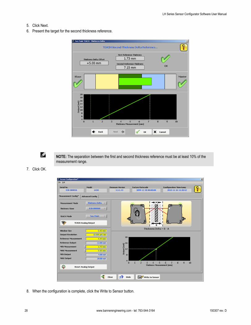
5. Click Next.6. Present the target for the second thickness reference.
NOTE: The separation between the first and second thickness reference must be at least 10% of themeasurement range.
7. Click OK.
8. When the configuration is complete, click the Write to Sensor button.
LH Series Sensor Configurator Software User Manual
28 www.bannerengineering.com - tel: 763-544-3164 150307 rev. D
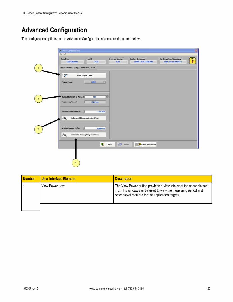
Advanced ConfigurationThe configuration options on the Advanced Configuration screen are described below.
Number User Interface Element Description
1 View Power Level The View Power button provides a view into what the sensor is see-ing. This window can be used to view the measuring period andpower level required for the application targets.
LH Series Sensor Configurator Software User Manual
150307 rev. D www.bannerengineering.com - tel: 763-544-3164 29

Number User Interface Element Description
Power Mode Auto Default, which lets the sensor automatically adjustlaser power and measuring period as necessary.
Max Speed Can be set to lock the sensor's measuring period at0.25 ms (maximum measurement rate of 4kHz).The sensor will still be able to adjust laser powerautomatically.
LimitedPower
If Limited Power is selected, the Max Power Levelcan be set below 100% power. This can be used toignore zones between targets.
2 Output Filter The Output Filter is a 1st order low-pass filter which can be used tofilter both the Analog Output and the Digital Output. The low-pass fil-ter tau ( ) is calculated as follows:
= # of Measurements X Measuring Period
The Measuring Period is the internal period for a Displacementmeasurement (0.25ms), or the Network Output Timer value for aThickness Delta measurement. After one , 63% of the measure-ment value is present at the output, rising to 99.9% after five .
3 Thickness Delta Offset The Thickness Delta Offset parameter can be adjusted when theideal sensor separation cannot be achieved due to application re-
LH Series Sensor Configurator Software User Manual
30 www.bannerengineering.com - tel: 763-544-3164 150307 rev. D

Number User Interface Element Description
strictions. The Thickness Delta Offset can also be calibrated precise-ly with a wizard to remove minor offset errors introduced by setuperrors. Calibrating the Thickness Delta Offset will enable the sensorto measure accurate thicknesses as well as accurate thickness del-tas.
4 Analog Output Offset The Analog Output Offset parameter can be adjusted to compensatefor offset errors introduced by components external to the sensor.The Analog Output Offset can also be calibrated precisely with awizard.
Thickness Delta OffsetThe Thickness Delta Offset parameter can be adjusted when the ideal sensor separation cannot be achieved due to application restric-tions. The Thickness Delta Offset can also be calibrated precisely with a wizard to remove minor offset errors introduced by setup errors.Calibrating the Thickness Delta Offset will enable the sensor to measure accurate thicknesses as well as accurate thickness deltas.
To perform a calibration of the Thickness Delta Offset:
1. Present a target with a known reference thickness to the master and slave sensors. Enter the known thickness value into the Cali-bration Target Thickness field.
2. Enter a Minimum Target Thickness and Maximum Target Thickness required for the application. The wizard will compute the ideal
separation of the sensors.3. Click Next.4. The next screen confirms the actual sensor separation. If the ideal sensor separation cannot be achieved due to application restric-
tions, the actual separation can be entered.
LH Series Sensor Configurator Software User Manual
150307 rev. D www.bannerengineering.com - tel: 763-544-3164 31

5. Click Next.6. The final step allows the desired thickness value of the calibration target to be set.
LH Series Sensor Configurator Software User Manual
32 www.bannerengineering.com - tel: 763-544-3164 150307 rev. D

7. Press Finish to complete the calibration process.
NOTE: Upon completion the calibrated thickness delta offset will be automatically written to the sensor.
Analog Output OffsetThe Analog Output Offset parameter can be adjusted to compensate for offset errors introduced by components external to the sensor.The Analog Output Offset can also be calibrated precisely with a wizard.
To perform a calibration of the Analog Output Offset:
1. Measure the sensor's analog output with a multimeter (or equivalent), and present a target within the sensor's analog output meas-urement window. For best results, it is recommended to present a target close to the taught reference.
2. Depending upon the measurement mode (Displacement or Thickness Delta) of the sensor, the Analog Output Calibration windowwill appear like one of the two following screen shots.
LH Series Sensor Configurator Software User Manual
150307 rev. D www.bannerengineering.com - tel: 763-544-3164 33

3. Enter the actual analog output value that is measured. The wizard will calculate the required analog output offset value (this value
will be rounded to the nearest 5 µA).4. Press OK to finish the calibration process.
NOTE: Upon completion the calibrated analog output offset will be automatically written to the sensor.
Thickness Delta Alignment ToolThe LH Series Configurator has several windows that display an alignment tool for Thickness Delta measurements. This tool is intendedto assist in correctly positioning a target for a valid thickness delta measurement.
2
1
3
5 647
LH Series Sensor Configurator Software User Manual
34 www.bannerengineering.com - tel: 763-544-3164 150307 rev. D

Element Description
1 Thickness Delta Status The overall status of the thickness delta measurement. A red X with an error mes-sage below it indicates an error.
2 Slave Status The status of the slave's displacement measurement. A red X indicates an error.
3 Master Status The status of the master's thickness delta measurement. A red X indicates an er-ror. A yellow question mark indicates the Master's measurement is unknown.
4 Slave Only Region (Yellow)* The region inside the slave's measurement range, but outside the master's.
5 Master/Slave Region (Dark Green)* The overlap of the master and slave's measurement range.
6 Master Only Region (Blue)* The region inside the master's measurement range, but outside the slave's.
7 Target The measured target's thickness is represented by the bright green box.
* Please note that the regions displayed represent the internal calculations of the sensors, and the amount of overlap may not corre-spond to the physical sensor separation.
Tip: For Proper Thickness Delta Alignment:
• The slave must be seeing a target within its measurement range. The slave's edge of the target must lie in the yellow or dark greenregion. For best results, position this edge near the middle of the combined regions.
• The master must be seeing a target within its measurement range. The master's edge of the target must lie in the blue or dark greenregion. For best results, position this edge near the middle of the combined regions.
• A valid thickness measurement must be between 0 mm and the sensors' model measurement range. Invalid measurements canoccur if the master/slave separation is incorrect, or if the Thickness Delta Offset has not been properly calibrated.
• LH sensors can be used in thickness delta measurement applications where the nominal material thickness is greater than the meas-urement range. In such cases you should increase the distance apart by the nominal thickness of the material that is being meas-ured.
LH Series Sensor Configurator Software User Manual
150307 rev. D www.bannerengineering.com - tel: 763-544-3164 35

LH Network and Measurements
LH Network TabThis screen is used to verify network status including all the sensors on the network. A green checkmark in the upper-left of the screenindicates a properly configured network. A network error is indicated with a red X in the upper-left of the screen with the problem highligh-ted in red.
• Clicking on the green Configure Sensor cells in the LH Network Status table launches the Sensor Configuration window.• Clicking the Network Setup button launches the Network Setup window.• Clicking the Scan Network button causes the LH Network to be re-scanned
LH Series Sensor Configurator Software User Manual
36 www.bannerengineering.com - tel: 763-544-3164 150307 rev. D

Measurements TabThe Measurements tab is used for data acquisition for analysis and troubleshooting.
UI Description
1 Visual display of measurement data.
2 The statistics table displays measurement statistics from all the sensors on the network. Sensors can be selected andreordered in the table. The statistics can also be sorted by clicking on the column headers. The Plot column controlswhich sensors' data is displayed on the graph.
3 Data logging provides for saving data to a file. A new file can be created or the data can be appended to an existingfile.
4 The Setup button displays the Sampling Setup screen. The Start/Stop button starts and stops data acquisition.
5 Selects the set of data to calculate the statistics for the statistics table. Displayed means the statistics are calculatedonly on the measurements that are displayed on the graph. All means the statistics are calculated on all the measure-ments that have been collected since pressing the Start button.
6 Sets the scale for the x-axis in the display.
7 Sets the scale for the y-axis in the display. The y-axis can be set to auto-scale by selecting the Auto checkbox.
LH Series Sensor Configurator Software User Manual
150307 rev. D www.bannerengineering.com - tel: 763-544-3164 37
UI Description
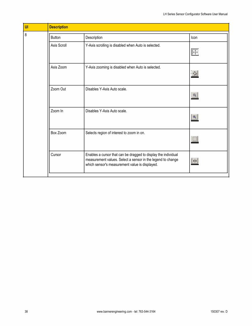
8 Button Description Icon
Axis Scroll Y-Axis scrolling is disabled when Auto is selected.
Axis Zoom Y-Axis zooming is disabled when Auto is selected.
Zoom Out Disables Y-Axis Auto scale.
Zoom In Disables Y-Axis Auto scale.
Box Zoom Selects region of interest to zoom in on.
Cursor Enables a cursor that can be dragged to display the individualmeasurement values. Select a sensor in the legend to changewhich sensor's measurement value is displayed.
LH Series Sensor Configurator Software User Manual
38 www.bannerengineering.com - tel: 763-544-3164 150307 rev. D
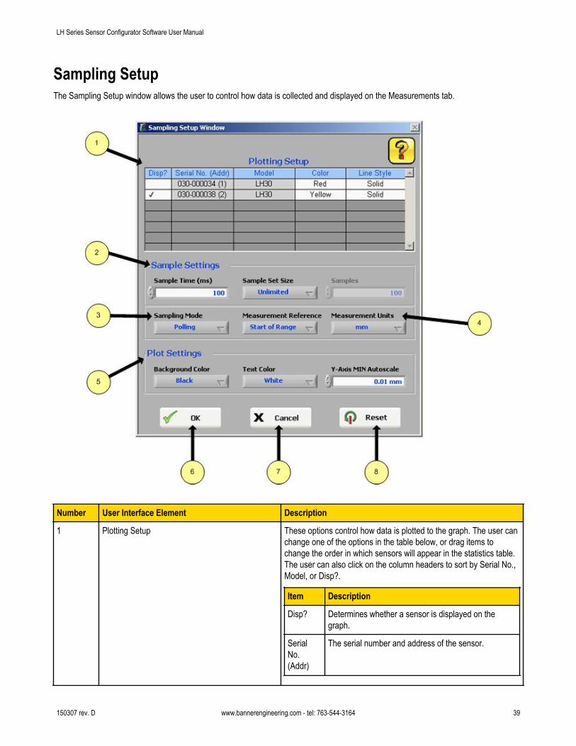
Sampling SetupThe Sampling Setup window allows the user to control how data is collected and displayed on the Measurements tab.
Number User Interface Element Description
1 Plotting Setup These options control how data is plotted to the graph. The user canchange one of the options in the table below, or drag items tochange the order in which sensors will appear in the statistics table.The user can also click on the column headers to sort by Serial No.,Model, or Disp?.
Item Description
Disp? Determines whether a sensor is displayed on thegraph.
SerialNo.(Addr)
The serial number and address of the sensor.
LH Series Sensor Configurator Software User Manual
150307 rev. D www.bannerengineering.com - tel: 763-544-3164 39

Number User Interface Element Description
Item Description
Model The model name of the sensor (LH30/LH80/LH150).
Color The line color of the sensor on the graph. Selectablefrom a drop-down list.
LineStyle
The line style of the sensor on the graph (solid/dash-ed/etc.). Selectable from a drop-downlist.
2 Sample Settings • Sample Time (ms) - In polling mode, the rate at which the LHSeries Configurator will poll the sensor(s) for a measurement. Instreaming mode, the rate at which the logfile and display will beupdated.
• Sample Set Size - If this option is set to fixed, the LH SeriesConfigurator will stop data collection after a user-selected num-ber of samples.
• Samples - If "Sample Set Size" is set to fixed, the number ofsamples before data logging is stopped.
3 Sampling Mode Controls how the data is collected from the sensor.
• Polling - The PC controls the LH Network and reads one net-work measurement at a time.
• Streaming - The LH Network is allowed to run and the LH Ser-ies Configurator receives the network measurements. This modeallows for the highest rate of data acquisition, but requires theNetwork Output Timer to be set.
4 Measurement Reference The point of reference for the logging and display of measurementdata.
• Start of Range - All measurements will be relative to the start ofthe sensor's measurement range.
• Mid-Range - All measurements will be relative to the mid-pointof the sensor's measuring range.
• TEACH Point - All measurements will be relative to the sensor'staught reference point.
5 Plot Settings • Background Color - The background color of the graph.• Text Color - The text color of the graph (axis label/legend).• Y-Axis MIN Autoscale - The minimum separation between the
minimum and maximum value of the y-axis when auto-scaling isenabled.
6 OK Button Accepts the changes and exits the window.
7 Cancel Button Reverts to previous settings when window was opened and exits thewindow.
8 Reset Button Reverts to the default settings from when the LH Series Configuratorwas installed.
LH Series Sensor Configurator Software User Manual
40 www.bannerengineering.com - tel: 763-544-3164 150307 rev. D

LH Series Serial Communication
LH Network ProtocolThe LH Network protocol is used for communication on the RS-485 bus to the LH Series Sensors. This protocol is designed especially fora maximum rate of data transfer with little protocol overhead. Diagrammatically, an LH Network on the RS-485 bus is as follows:
Figure 2. Example diagram of an LH network
Each sensor on the network has a unique 8-bit address. The communication process is as follows:• The controller, transmits the address of the first sensor at address 1. This sensor recognizes its own address and responds by trans-
mitting its current measurement values as a 16-bit word in big endian order.• The first sensor then activates the second sensor by transmitting address 2. The second sensor responds by transmitting its current
measurement value and address 3.• This process repeats until the last sensor transmits its measurement value and the address for the next sensor (which is unused).
The controller recognizes the unused address and knows that all the sensors on the network have transmitted their correspondingmeasurement values and the communication process is complete.
• In terms of structure, the communication process is similar to the "token ring" mechanism where each of the sensor addresses trans-mitted corresponds to the "token".
• To achieve minimal overhead in the transfer, the data is transferred in binary form. In order to clearly distinguish between data andaddresses, the address bytes use a mark parity bit (1, "high") and the data bytes use a space parity bit (0, "low").
• The bit sequence of the individual characters on the RS-485 bus corresponds to the protocol of an RS-232 transfer.
Diagrammatically, the bit order is as follows:
Stop BitStart8 bits
LS MS
Parity BitAddress = High
Data = Low
Figure 3. Bit order of a character illustration
A diagram of an example communication process with two sensors:
Figure 4. Example communication process with two sensors
The controller starts the process by transmitting the address of sensor 1. Sensor 1 responds by transmitting its measurement value andthe address of sensor 2. Sensor 2 responds by transmitting its measurement value and the unused address of sensor 3. The controllerrecognizes the unused address and knows the process is complete.
150307 rev. D www.bannerengineering.com - tel: 763-544-3164 41

Measurement Values
Valid measurement values fall within the range of 2768-62768. The measurement range of the sensor is divided evenly across the 60000count range. When no valid target is within the measurement range, a measurement value of 65534 will be provided.
Network Output Timer
If the Network Output Timer is enabled, the sensor at address 1 takes on the additional role of being the controller. As the controller, thesensor at address 1 will first transmit its own address of 1 along with its measurement value, followed by the next address of 2. TheNetwork Output Timer value determines the rate at which this automatic communication process happens.
In order to stop/start this automatic communication process, a controller can send the following single byte commands:
Command Byte Value
Stop 0x51
Start 0x57
The command bytes use a mark parity bit (1, "high"). The stop command may need to be sent multiple times if the Network Output Timeris set to a very fast value.
Minimum Network Output Timer
Number of Sensors
Baudrate (bps) 1 2 32
57600 1 ms 2 ms 32 ms
115200 0.5 ms 1 ms 16 ms
230400 0.25 ms 0.5 ms 8 ms
LH Series Sensor Configurator Software User Manual
42 www.bannerengineering.com - tel: 763-544-3164 150307 rev. D
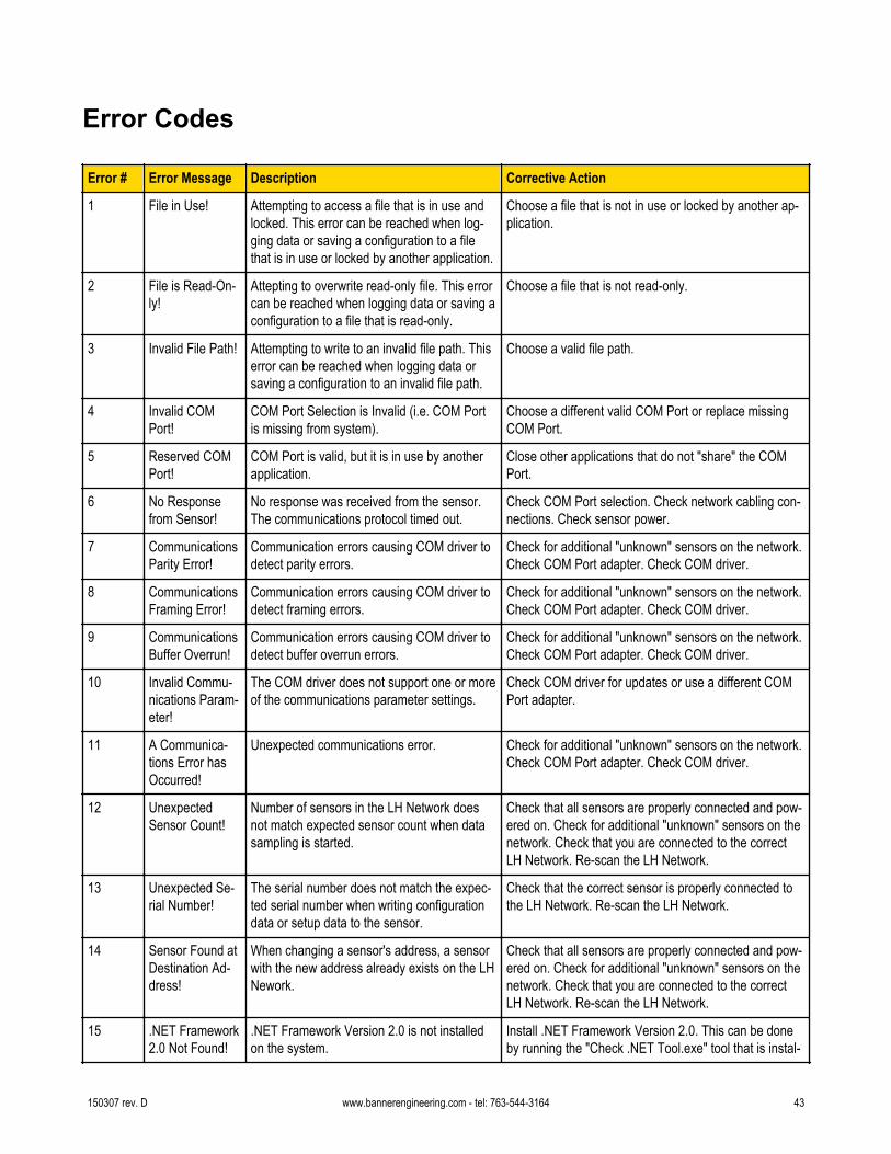
Error Codes
Error # Error Message Description Corrective Action
1 File in Use! Attempting to access a file that is in use andlocked. This error can be reached when log-ging data or saving a configuration to a filethat is in use or locked by another application.
Choose a file that is not in use or locked by another ap-plication.
2 File is Read-On-ly!
Attepting to overwrite read-only file. This errorcan be reached when logging data or saving aconfiguration to a file that is read-only.
Choose a file that is not read-only.
3 Invalid File Path! Attempting to write to an invalid file path. Thiserror can be reached when logging data orsaving a configuration to an invalid file path.
Choose a valid file path.
4 Invalid COMPort!
COM Port Selection is Invalid (i.e. COM Portis missing from system).
Choose a different valid COM Port or replace missingCOM Port.
5 Reserved COMPort!
COM Port is valid, but it is in use by anotherapplication.
Close other applications that do not "share" the COMPort.
6 No Responsefrom Sensor!
No response was received from the sensor.The communications protocol timed out.
Check COM Port selection. Check network cabling con-nections. Check sensor power.
7 CommunicationsParity Error!
Communication errors causing COM driver todetect parity errors.
Check for additional "unknown" sensors on the network.Check COM Port adapter. Check COM driver.
8 CommunicationsFraming Error!
Communication errors causing COM driver todetect framing errors.
Check for additional "unknown" sensors on the network.Check COM Port adapter. Check COM driver.
9 CommunicationsBuffer Overrun!
Communication errors causing COM driver todetect buffer overrun errors.
Check for additional "unknown" sensors on the network.Check COM Port adapter. Check COM driver.
10 Invalid Commu-nications Param-eter!
The COM driver does not support one or moreof the communications parameter settings.
Check COM driver for updates or use a different COMPort adapter.
11 A Communica-tions Error hasOccurred!
Unexpected communications error. Check for additional "unknown" sensors on the network.Check COM Port adapter. Check COM driver.
12 UnexpectedSensor Count!
Number of sensors in the LH Network doesnot match expected sensor count when datasampling is started.
Check that all sensors are properly connected and pow-ered on. Check for additional "unknown" sensors on thenetwork. Check that you are connected to the correctLH Network. Re-scan the LH Network.
13 Unexpected Se-rial Number!
The serial number does not match the expec-ted serial number when writing configurationdata or setup data to the sensor.
Check that the correct sensor is properly connected tothe LH Network. Re-scan the LH Network.
14 Sensor Found atDestination Ad-dress!
When changing a sensor's address, a sensorwith the new address already exists on the LHNework.
Check that all sensors are properly connected and pow-ered on. Check for additional "unknown" sensors on thenetwork. Check that you are connected to the correctLH Network. Re-scan the LH Network.
15 .NET Framework2.0 Not Found!
.NET Framework Version 2.0 is not installedon the system.
Install .NET Framework Version 2.0. This can be doneby running the "Check .NET Tool.exe" tool that is instal-
150307 rev. D www.bannerengineering.com - tel: 763-544-3164 43
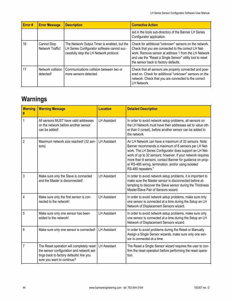
Error # Error Message Description Corrective Action
led in the tools sub-directory of the Banner LH SeriesConfigurator application.
16 Cannot StopNetwork Traffic!
The Network Output Timer is enabled, but theLH Series Configurator software cannot suc-cessfully stop the LH Network protocol.
Check for additional "unknown" sensors on the network.Check that you are connected to the correct LH Net-work. Remove sensor at address 1 from the LH Networkand use the "Reset a Single Sensor" utility tool to resetthe sensor back to factory defaults.
17 Network collisiondetected!
Communications collision between two ormore sensors detected.
Check that all sensors are properly connected and pow-ered on. Check for additional "unknown" sensors on thenetwork. Check that you are connected to the correctLH Network.
WarningsWarning#
Warning Message Location Detailed Description
1 All sensors MUST have valid addresseson the network before another sensorcan be added!
LH Assistant In order to avoid network setup problems, all sensors onthe LH Network must have their addresses set to value oth-er than 0 (unset), before another sensor can be added tothe network.
2 Maximum network size reached! (32 sen-sors)
LH Assistant An LH Network can have a maximum of 32 sensors. Note:Banner recommends a maximum of 8 sensors per LH Net-work. The LH Series Configurator does support an LH Net-work of up to 32 sensors; however, if your network requiresmore than 8 sensors, contact Banner for guidance on prop-er RS-485 wiring, termination, and/or using isolatedRS-485 repeaters."
3 Make sure only the Slave is connectedand the Master is disconnected!
LH Assistant In order to avoid network setup problems, it is important tomake sure the Master sensor is disconnected before at-tempting to discover the Slave sensor during the ThicknessMaster/Slave Pair of Sensors wizard.
4 Make sure only the first sensor is con-nected to the network!
LH Assistant In order to avoid network setup problems, make sure onlyone sensor is connected at a time during the Setup an LHNetwork of Displacement Sensors wizard.
5 Make sure only one sensor has beenadded to the network!
LH Assistant In order to avoid network setup problems, make sure onlyone sensor is connected at a time during the Setup an LHNetwork of Displacement Sensors wizard.
6 Make sure only one sensor is connected! LH Assistant In order to avoid problems during the Reset or ManuallyAssign a Single Sensor wizards, make sure only one sen-sor is connected at a time.
7 The Reset operation will completely resetthe sensor configuration and network set-tings back to factory defaults! Are yousure you want to continue?
LH Assistant The Reset a Single Sensor wizard requires the user to con-firm the reset operation before performing the reset opera-tion.
LH Series Sensor Configurator Software User Manual
44 www.bannerengineering.com - tel: 763-544-3164 150307 rev. D

Warning#
Warning Message Location Detailed Description
8 The Slave sensor is an LH###. The Mas-ter sensor is an LH###. The Slave andMaster MUST be the same model!
LH Assistant Thickness Delta measurement mode requires the Masterand Slave sensors to be the same model (i.e. LH30, LH80,LH150). Use identical models for both sensors.
9 The Thickness Delta measurement moderequires the Master sensor to have agreater address than the Slave sensor!
Network Setup The Master sensor must have an address greater than theSlave sensor for a Thickness Delta measurement. TheSlave sends its displacement measurement to the Masterusing the LH Network protocol. The Slave must be aheadof the Master in the serial communication process.
10 The Network Output Timer cannot be dis-abled when a Thickness Delta measure-ment mode is configured within the LHNetwork!
Network Setup The Network Output Timer is required for a Thickness Del-ta measurement. If at least one sensor in the LH Network isconfigured for a Thickness Delta measurement mode, theNetwork Output Timer cannot be disabled.
11 Changing the Output Timer will affect theOutput Filtering of Thickness Deltameasurements within the network! Areyou sure you want to continue?
Network Setup The Thickness Delta measurement mode uses the NetworkOutput Timer as its measuring period. Output Filtering on aThickness Delta measurement will be affected by changesto the Network Output Timer value.
12 There are Network Setup changes thathave not been written to the network.Closing the LH Network Setup windowwill discard these changes. Are you sureyou want to continue?
Network Setup Network Setup changes are only written to the network bypressing the "Write to Network" button. Closing the windowbefore pressing the button will discard all the changes."
13 The sensor cannot be set to ThicknessDelta measurement mode because nocompatible slaves are available!
Sensor Configura-tion
A compatible Slave must be available within the LH Net-work before a sensor can be configured into a ThicknessDelta Master. Compatible slaves are sensors of the samemodel (i.e. LH30, LH80, LH150) and with addresses lessthan the Master's address.
14 This sensor is a slave to the master sen-sor <Serial No.> for a Thickness Deltameasurement. The sensor cannot beconfigured to Thickness Delta measure-ment mode at this time!
Sensor Configura-tion
Thickness Delta Slave sensors cannot be configured to beThickness Delta Masters. Change the Master's slave sen-sor prior to this operation.
15 This sensor is a slave to the master sen-sor <Serial No.> for a Thickness Deltameasurement. Changing the slave'sPower Mode or Output Filter configuratonwill affect the Thickness Delta measure-ment. Are you sure you want to contin-ue?
Sensor Configura-tion
Changes to a Thickness Delta Slave's Power Mode or Out-put Filter configuration can affect the accuracy of a Thick-ness Delta Master's measurement.
16 Analog Ouput Span < # mm! Sensor Configura-tion
The Analog Output Span must be >= 10% of the full scalemeasurement range. # will be 1, 4, or 10mm for an LH30,LH80, or LH150 respectively.
17 Far Measurement < Near Measurement! Sensor Configura-tion
For Displacement measurement mode, the Far Measure-ment must be > Near Measurement!
18 MAX Measurement < MIN Measurement! Sensor Configura-tion
For Thickness Delta measurement mode, the MAX Meas-urement must be > MIN Measurement!
LH Series Sensor Configurator Software User Manual
150307 rev. D www.bannerengineering.com - tel: 763-544-3164 45

Warning#
Warning Message Location Detailed Description
19 The configuration changes must be writ-ten to the sensor prior to the TEACH. Doyou want to write the configurationchanges to the sensor?
Sensor Configura-tion
The TEACH procedure requires certain configurationchanges to be written to the sensor prior to enteringTEACH. The configuration parameters that are requiredare: Measurement Mode, Power Mode, Output Filter,Thickness Delta Slave, Thickness Delta Offset
20 The Network Output Timer must be ena-bled to TEACH in Thickness Delta Meas-urement Mode!
Sensor Configura-tion
The Thickness Delta measurement mode uses the NetworkOutput Timer as its measuring period. The Network OutputTimer must be enabled for Thickness Delta measurementmode to work properly.
21 The Network Output Timer must be ena-bled to edit the Output Filter when thesensor is configured for Thickness DeltaMeasurement Mode!
Sensor Configura-tion
The Thickness Delta measurement mode uses the NetworkOutput Timer as its measuring period. Output Filtering on aThickness Delta measurement requires the Network OutputTimer to be enabled to work properly.
22 The sensor must be configured for Thick-ness Delta Measurement Mode to Cali-brate the Thickness Delta Offset!
Sensor Configura-tion
Calibration of the Thickness Delta Offset can only be per-formed when a sensor is configured for Thickness Deltameasurement mode.
23 The Network Output Timer must be ena-bled to Calibrate the Thickness Delta Off-set!
Sensor Configura-tion
The Thickness Delta measurement mode uses the NetworkOutput Timer as its measuring period. The Network OutputTimer must be enabled for Thickness Delta measurementmode to work properly.
24 The configuration changes must be writ-ten to the sensor prior to the calibration.Do you want to write the configurationchanges to the sensor?
Sensor Configura-tion
The Thickness Delta Offset and Analog Output Offset cali-bration procedures require any configuration changes to bewritten to the sensor prior to entering calibration.
25 A temporary Thickness Delta Offset willbe written to the sensor. Press 'Yes' towrite a temporary Thickness Delta Offset-OR- Press 'No' to continue calibrationwith the current value.
Sensor Configura-tion
The Thickness Delta Offset Calibration procedure maywrite a temporary value to the sensor during the process.This step can be skipped by pressing No. If skipped, thecurrent value of the Thickness Delta Offset will be usedduring the final step of the process.
26 Calibration of the Thickness Delta Offsetwas interrupted. The sensor may be con-figured with a temporary Thickness DeltaOffset value.
Sensor Configura-tion
The Thickness Delta Offset Calibration procedure maywrite a temporary value to the sensor during the process. Ifthe calibration was interrupted, this temporary value maystill be configured in the sensor. Recalibrate or restore thefactory config to reset the temporary value.
27 The configuration file was created for anLH### model. The sensor is an LH###model and requires a compatible configu-ration.
Sensor Configura-tion
LH sensor configurations cannot be interchanged betweenmodels. LH30 sensors require LH30 configurations, LH80sensors require LH80 configurations, etc.
28 There are Sensor Configuration changesthat have not been written to the sensor.Closing the LH Sensor Configuration win-dow will discard these changes. Are yousure you want to continue?
Sensor Configura-tion
Sensor Configuration changes are only written to the sen-sor by pressing the "Write to Sensor" button. Closing thewindow before pressing the button will discard all thechanges."
29 Streaming sampling mode requires theNetwork Output Timer to be enabled.
MeasurementsTab
The streaming sampling mode uses the Network OutputTimer to facilitate data acquisition. The Network OutputTimer must be enabled for Streaming sampling mode towork properly.
LH Series Sensor Configurator Software User Manual
46 www.bannerengineering.com - tel: 763-544-3164 150307 rev. D

Finding and Fixing FaultsCaution!
Only a qualified electrician is allowed to work on the device's electrical components.
The laser unit contains extremely sensitive components. For this reason, never attempt to repair thelaser unit yourself. We do not take any responsibility for damage resulting from improper use.
Observe the laser protection regulations. Never look directly into the laser beam.
Error Cause Solution*
Green LED not lit No power supply Check power supply
Amber LED not lit Target not in measurement range Check measurement distance and realign if nec-essary
No laser spot The sensor is not supplied with a 18-30 VDC oper-ating voltage.
Supply sensor with the correct operating voltage.Check that the green LED on the sensor is lit.
Very brightly lit fault lamp Shade off the source of interference radiation
Electronic defect Contact Banner
Incorrect measurement Optical window dirty Clean window thoroughly
Change position of sensors Realign the sensors
Target temporarily leaving the measurement range Set measurement range so that the target cannotleave the measurement range
Very brightly lit fault lamp Shade off the source of interference radiation
Electronic defect Contact Banner
* If the system fails to operate perfectly after these inspections, contact the factory for assistance.
LH Series Sensor Configurator Software User Manual
150307 rev. D www.bannerengineering.com - tel: 763-544-3164 47