1503-6C1412 - Кондиционеры...
48
COMMERCIAL AIR CONDITIONERS Water Cooled Centrifugal Chiller standard efficiency:450-2200Ton High efficiency:650-2200Ton R134a
Transcript of 1503-6C1412 - Кондиционеры...

1503-6C1412
COMMERCIAL AIR CONDITIONERS
Commercial Air Conditioner Business UnitsMidea GroupAdd: West Region of Midea Commercial Air Conditioner Department, Industry Avenue,
Beijiao, Shunde, Foshan, Guangdong, P. R. China
Postal code: 528311
Tel: +86-757-26338346 Fax: +86-757-22390205
http://global.midea.com.cn
http://www.midea.com
Note: The data in this book may be changed without notice for further improvement
on quality and performance.
Ver.2014.12
D e a l e r i n f o r m a t i o n
Water Cooled Centrifugal Chillerstandard efficiency:450-2200TonHigh efficiency:650-2200TonR134a

Midea Central Air-conditionerEntering into the 21st century, the energy has increasingly becomes as a global issue concerning the sus-tainable development of human-beings. In China, the construction power consumptions take 30% of the totals in the society. However, the power consumptions of air conditioners are 40%-50% of construction power consumptions. With progressive economy, various large-scale constructions are built up every-where. Thus, building energy has become a common responsibility of the society and an obligation for every air-conditioner supplier
In the central air-conditioning industry, Midea Central Air-conditioner has been committed to the air-conditioning technology R & D and innovation. From the Chinese first centrifugal chiller to the first full falling-film dual stages centrifugal chiller, Midea has been trying for creating comfortable, energy-saving and environment friendly equipment to the world.The ultra-efficient two-stage compression centrifugal chiller can be applied to a variety of energy-saving projects. It is the ideal choice for urban building and makes a significant contribution to the city building energy saving.
Successfully designed and manufactured the first Chinese centrifugal chi l ler , awarded the National Science and Technology Achieve-ment.
Cooperating with Hitachi, manufactured 2 series w i t h 1 2 m o d e l s o f Chongqing General Hita-chi centrifugal chillers.
Developed R134a cen-trifugal chiller used in the Qinshan Nuclear Power Plant in January 1999, awarded the National Ninth Five-Year Plan Excellent Technology Innovation.
The R134a (LC) series centrifugal chiller was named as the national key product.
Launched the f i r s t Chinese VSD (Variable Speed Drive ) centrifu-gal chiller unit.
Developed the Smart Star new generation Semi-hermetic cen-trifugal chiller.
Launched the centrifu-gal heat pump chiller units.
Launched the f i rs t super efficient centrifugal chiller with dual stage compressor and full falling-film evaporator.
Cooperating with Ameri-can York, manufactured centrifugal chillers.
Developed centrifugal chiller for the Hydrogen Bomb Engineering Project and marine centrifugal chiller for the Nuclear Submarine Project, awarded by the State Council, the Central Military Com-mission and National Defense Science and Technology.
01 02

The 1200kW air cooled testing lab is one of the largest air cooled product testing labs. It can simulate all the actual ambient temperature range from -20 ° C to 56 °C.It ensures all the air cooled chiller products work reliably in all temperature condition. Witness testing service is optional for all the clients to ensure the product performance.The 1200kW air cooled testing lab was certified by AHRI.
03 04
Air cooled screw chiller factory
Manufacturing capacity:
1000 units/Year
Centrifugal chiller factory
Manufacturing capacity:
500 units/Year
Water cooled screw chiller factory
Manufacturing capacity:
2000 units/Year
8800kW water cooled chiller performance testing stand
1500kW motor performance testing center
1200kW air cooled chiller performance testing lab
Contents05 Product Information07 Feature and Benefits08 Six Core Technologies15 Specification19 Dimension25 Construction27 Service Space28 Insulation29 Refrigeration Cycle
30 Microprocessor Control35 Centralized Control36 Typical Wiring Diagram39 Typical Piping and Cable Layout40 Mechanical Specification43 Selection Software44 Optional Items / Accessories45 Conversion Table
With half century experience in chiller industry, Midea Chongqing chiller manufacturing base is becoming one of the largest chiller companies in China. It covers an area of 800 Mu (137 acre), with a registered capital of 12.5 million US $ and a total investment of over 0.85 billion US$. There are 6 product series and over 100 model products including centrifugal chillers, screw water chillers, scroll water chillers, water-cooled packaged units, and central air-conditioning indoor terminal devices(AHU/FCU). Five chiller manufacture plants with 14 flexible production lines lead a manufacturing capacity of 500 units centrifugal chillers 1,000 units of air cooled screw 2,000 units of water cooled screw and 200,000 units of AHU products.
Strong R&D and manufacturing capacity make Midea Chongqing general become the fastest developing company in chiller industry. The chiller testing lab which is certified by China National Refrigeration Equipment Inspection Center has become one of the largest refrigeration testing capacity in the world. The engineer team with 100 top engineers and international chiller experts who have been working many years in structure, electricity, and performance testing and software aspect make Midea the headship in chiller industry. In the year of 2011 Midea CAC invested another 150 million RMB for testing lab as ARI testing stand, big capacity air cooled screw life span testing room, 1,500kW compressor motor testing lab etc.
Concentrating on energy-saving and environment protection, Midea Chongqing chiller factory commits itself to the reliable and high efficiency products for the world. The chiller products are widely used in different countries and obtain good public praise from the clients. The solutions for the Beijing capital international airport, Jakarta international airport, China rapid transit station win good feedback and commendation. Continuing with the past and opening up the future, Midea chiller brand will go further and create an illustrious future.
The 8800kW water cooled chiller testing stand is one of the most advanced testing facilities in the world. It is able to simulate all the chiller running conditions like Chinese National standard condition (7/12°C,30/35°C). Chinese industry condition (7/12 °C, 32/37 °C). AHRI testing condition (6.7/12.2 °C, 29.4/35 °C). It provides all precise testing data for the IPLV and NPLV calculation. Witness testing service is optional for all the clients to ensure the product performance.Every chiller will be tested in the stand before shipping.
The 1500kW compressor motor testing lab used to simulate all the working condition for the actual situation. Provide the electrical correct factor for all the compresors. The cooling capacity ranges from 1200kW to 8800kW. Evaporating temperature ranges from -20 °C to 40 ° C and condensing temperature ranges from 25 °C to 80 °C.It is one of the most advanced testing facility in China.

05 06
In 2013 Midea launched the third generation centrifugal chillers with higher efficiency and more compact size compared to the second generation. By using the advanced design platform the compressing efficiency and heat exchanging rate have been increased significantly. The full failing film heat exchange technology also be used to increase the efficiency and decrease the refrigerant charging volume up 40% less compared to the flooded type. It is a innovation to protect our environment and decrease the CO2 emission effectivly.
In order to cater to different efficiency requirement and consider the cost-effective for various investments Midea provides three class efficiency for the clients. Dual compressors can be customized for big capacity up to 4400Ton.
LC M S 101500
Omit for 380V 6: 6KV 10: 10KV
S: The compressor is double stage
Omit: The compressor is single stage
M: Standard efficiency typeH: High efficiency typeE: Super high efficiency typeCooling capacity 1500RT
R134a,centrifugal chiller
Product Information
Shell and tube condenser and flooded type evaporator
Advanced system control and user friendly screen
Gas cooled motorSemi-Hermetic
centrifugal compressorEconomizer in dual stages type
Environment friendly refrigeration
R134aR134a
The motor is cooled by refrigerant which ensures an excellent performance in various working condition and long life span. The motor is high efficiency type with higher power factor up to 97%.
The compressor is designed on Midea advanced design platform, the impeller and chamber are matching perfectly. The compressor equipped with less moving parts and compact size. By using the double layer design technology the noise a n d v i b r a t i o n c a n b e c o n t r o l l e d excellently.
The ecomomizer is used in the dual stages compressing.Midea unique design economizer improves the efficiency from 5% to 8% compared with the single stage.
The condenser is shell and tube type for easy service.Flooded type evaporator used in the s ingle sta lge product and fu l l fa l l ing f i lm evaprator used in dual stages chiller.
R134a is environment friendly gas with zero ODP (Ozone Depletion Potential) and very less GWP (G lob le Warming Potent i a l ) . The R134a refrigeration is no phase out gas and good choice for big chiller.
The system is control by industry type PLC with multiple function and good stability. It is open protocol of RS 485 which is compatible for BMS. The operation screen is user friendly with 10 inch colorful touchable screen.
Type Super high efficiency
Model LC**M LC**MS LC**H LC**HS LC**ES
COP(W/W) 7 ~7.11
Compression stage 1 2 1 2 2
Capacity(Ton) 450-1200 1200-2200 650-1100 1200-2200 1200-2200
Evaporator type Flooded type Full falling film Flooded type Full falling film Full falling film
Recommend power suply 380/400/415V 6kV/10kV 380V/6kV/10kV 6kV/10kV 6kV/10kV
Standard efficiency High efficiency
5.3~5.7 5.6~6.8
TONS
Stardard Efficiency
High Efficiency
Super High Efficiency
VSD
0 500 1000 1500 2000 2500 3000 3500 4000 4500

Oil seal
The small gear shaft
Adjustable diffuser The high-level oil tank
Motor shaft
Motor thrust bearing
Spray tube
Balance pipe
Adjustable guide vane
Driving gear
The driving gear radial bearing
Impeller
Pinion shaft
Rotor
Seal assembly
The power delivery surface
Full falling film heat exchange technology(PATENT NO: 20121041053.9 201220552298)Unique spraying technology makes the liquid refrigerant film formed on the tube surface and then evaporation. By using this technology the heat exchange rate increase 3 to 8 % and refrigerant charge decrease 40%.
Inlet guide vane (IGV) match with movable diffuser (PATENT NO. : ZL01 2 56825.2)The IGV matches with the moveable diffuser to ensure the compressor working stable in low partial load without any surge and stall. Capacity adjustment is from 10% to 100%.
Keyless impeller coupling with high speed shaft (PATENT NO.: ZL 01 2 56824.4)The impeller is coupling with the shaft without any key to eliminate the stress to the shaft. Ensure the high speed shaft working stable and long life span.
Feature and Benefits Six Core Technologies
07 08
Explore the Frontier of Aerodynamic Technology
Full Flow Pass Optimization, further increases the efficiencyNewly designed three-dimensional flow impeller, coupling with the optimized volute, ensures the flow velocity and maximizes the efficiency
Midea centrifugal compressor adopts the over-hung volute thus compacting the structure.
Volute Model
The gas flow perfectly matches the interior flow channel, hence the loss of impact reduced.
Aerodynamic loss balance design reduces the aerodynamic noise
Turbulence Reducing Blade
Entire Optimization
The newly designed high efficient three-dimension flow alloy impeller, produced in German GMD 5-aixs machine center, has high machining precision and reduces 30% of thickness for the impeller, thus reducing the axial force loss and separation loss.
High Efficient Three-dimension Flow Impeller
09 10
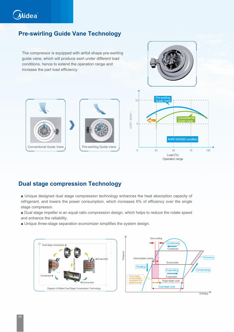
Pre-swirling Guide Vane Technology
Dual stage compression Technology
The compressor is equipped with airfoil shape pre-swirling guide vane, which will produce swirl under different load conditions, hence to extend the operation range and increase the part load efficiency.
■ Unique designed dual stage compression technology enhances the heat absorption capacity of refrigerant, and lowers the power consumption, which increases 6% of efficiency over the single stage compressor.■ Dual stage impeller is an equal ratio compression design, which helps to reduce the rotate speed and enhance the reliability.■ Unique three-stage separation economizer simplifies the system design.
Conventional Guide Vane Pre-swirling Guide Vane
Pre-swirlingGuide Vane
Conventional Guide Vane
AHRI 550/590 condition
Load (%)Operation range
Pres
sure
Intermediate cooling
Throttling
Dual-stage compression increases the performance
Condenser
Condensing
Sub-cooling
Economizer
Evaporating
EvaporatorSinge-stage cycle
Dual-stage cycle
Economy
Compressing
Enthalpy
Dual stage compressor
Condenser
Evaporator
Economizer
Gas
Inje
ctio
n
Diagram of Midea Dual Stage Compression Technology
Creative Heat-exchanging Technology
Full falling-film Evaporating TechnologyThe unique full falling-film evaporating technology: spraying technology makes the liquid refrigerant form and evaporate on the surface of evaporating tubes, which significantly boosts the heat-exchanging efficiency and reduces 40% refrigerant charge. Midea adopts patented technologies to ensure refrigerant distributed evenly and avoid non liquid on part tubes, which extend the potential heat-exchanging capacity to the full and enhance the efficiency of the whole system.
CondenserHigh efficient heat-exchanger and optimized structure enhance the heat exchanging performance. The design of reverse flow sub-cooling chamber with multiple turbulences increases the sub-cooling degree and improves the performance.
Cooling water outlet
Cooling water inlet
Refrigerant gas inlet
Refrigerant liquid outlet
Reverse flow sub-cooling chamber Baffle board
40% reduction of refrigerant charge
Flooded type
Full falling film achieved 40% less refrigerant charge than flooded type
Mixed falling film
Full falling film achieved 25% less refrigerant charge than the mixed flooded type
Full falling film
Almost zero percent liquid level
Patent No:

09 10
Pre-swirling Guide Vane Technology
Dual stage compression Technology
The compressor is equipped with airfoil shape pre-swirling guide vane, which will produce swirl under different load conditions, hence to extend the operation range and increase the part load efficiency.
■ Unique designed dual stage compression technology enhances the heat absorption capacity of refrigerant, and lowers the power consumption, which increases 6% of efficiency over the single stage compressor.■ Dual stage impeller is an equal ratio compression design, which helps to reduce the rotate speed and enhance the reliability.■ Unique three-stage separation economizer simplifies the system design.
Conventional Guide Vane Pre-swirling Guide Vane
Pre-swirlingGuide Vane
Conventional Guide Vane
AHRI 550/590 condition
Load (%)Operation range
Pres
sure
Intermediate cooling
Throttling
Dual-stage compression increases the performance
Condenser
Condensing
Sub-cooling
Economizer
Evaporating
EvaporatorSinge-stage cycle
Dual-stage cycle
Economy
Compressing
Enthalpy
Dual stage compressor
Condenser
Evaporator
Economizer
Gas
Inje
ctio
n
Diagram of Midea Dual Stage Compression Technology
Creative Heat-exchanging Technology
Full falling-film Evaporating TechnologyThe unique full falling-film evaporating technology: spraying technology makes the liquid refrigerant form and evaporate on the surface of evaporating tubes, which significantly boosts the heat-exchanging efficiency and reduces 40% refrigerant charge. Midea adopts patented technologies to ensure refrigerant distributed evenly and avoid non liquid on part tubes, which extend the potential heat-exchanging capacity to the full and enhance the efficiency of the whole system.
CondenserHigh efficient heat-exchanger and optimized structure enhance the heat exchanging performance. The design of reverse flow sub-cooling chamber with multiple turbulences increases the sub-cooling degree and improves the performance.
Cooling water outlet
Cooling water inlet
Refrigerant gas inlet
Refrigerant liquid outlet
Reverse flow sub-cooling chamber Baffle board
40% reduction of refrigerant charge
Flooded type
Full falling film achieved 40% less refrigerant charge than flooded type
Mixed falling film
Full falling film achieved 25% less refrigerant charge than the mixed flooded type
Full falling film
Almost zero percent liquid level
Patent No:

11 12
Free Cooling Technology-Refrigeration Migration
Prospective-Control Logic Compressor Reliability
Thermodynamic Performance Test
The microcomputer control system has such as the trend prediction, self-diagnosis, self-adjustment and safety protection. capable to predict real load change according to the target values and historical load levels, prospectively modify the operation load and prevent energy waste
Centrifugal compressors are dynamic machines in which rotating impellers accelerate the gas. Main flow is radial. The velocity head is converted into pressure, partially in the rotating elements and partially in stationary diffusers.
Midea third generation “Smart Start” centrifugal compressors are carefully tested throughout the manufacturing process in order to guarantee a perfect match to their design criteria and to assure long lasting, continuous operation.All components were exclusively designed and tested for re-confirming it’s reliability. The following tests are typically carried out on components and assembled machines: Casing: hydraulic pressure test and hydraulic blasting testing Shaft: Ultrasonic testing and tensile testing Impellers: Ultrasonic and dynamically balanced testing Impeller/Rotor: Over speed testing Motor wiring: 3 phase resistance balance testing Other mechanical run test Performance testing for each chiller before deliveryBeside the mechanical testing the Thermodynamic Performance Test ensure the entire compressor working at any conditions.
Note:AHRI condition testing example
Operation Range, Condensing Temperature, Evaporating/Suction Temperature
Temperature change prospective control
Temperature change under Prospective-Control
Con
dens
ing
tem
pera
ture
Ref
riger
ant L
ow T
empe
ratu
re li
mit
Com
pres
sor c
urre
nt li
mita
tion
Extended operation rangeTh
e max
. com
press
ion ra
tio
Condensing temperature lower limitation
Evaporating /suction temperature
Midea 3G Centrifugal Chiller features the ‘Free Cooling Technology’. When the outdoor temperature is low and large commercial buildings’ interior spaces may need cooling, the main unit will work on ‘Free Cooling’ mode. Free cooling is the production of chilled water Without running compressor.The relative warm, and the energy is carried directly to the low pressure condenser, where it is cooled and condensed by the water from the cooling tower. Then the low temperature liquid refrigerant flows to the evaporator driving by gravity, then naturally circulates. The cost is saved due to the compressor’s inactivity, zero power consumption of the main unit.The principle is that the refrigerant tends to move towards the coldest point in a refrigeration circuit. It can be used generally in the transition season such as late fall, winter and early spring.
Off
High temperature
Condenser
Evaporator
Lowtemperature
Chilling water temperature in AHRI condition
100%90%
80%70%
60%
Hea
d Fr
actio
n
Flow Fraction.25 .50 .75 1.0
.8
.6
.4
Design point
40%30%
20%
50%
.2
1.
.0.0
IGV
=90 degrees
IGV
=70 degrees
IGV
=50 degrees
IGV
=30 degrees
IGV
=20 degrees
IGV
=10 degrees
Surge Line
Surge Line
Constant water temperature

11 12
Free Cooling Technology-Refrigeration Migration
Prospective-Control Logic Compressor Reliability
Thermodynamic Performance Test
The microcomputer control system has such as the trend prediction, self-diagnosis, self-adjustment and safety protection. capable to predict real load change according to the target values and historical load levels, prospectively modify the operation load and prevent energy waste
Centrifugal compressors are dynamic machines in which rotating impellers accelerate the gas. Main flow is radial. The velocity head is converted into pressure, partially in the rotating elements and partially in stationary diffusers.
Midea third generation “Smart Start” centrifugal compressors are carefully tested throughout the manufacturing process in order to guarantee a perfect match to their design criteria and to assure long lasting, continuous operation.All components were exclusively designed and tested for re-confirming it’s reliability. The following tests are typically carried out on components and assembled machines: Casing: hydraulic pressure test and hydraulic blasting testing Shaft: Ultrasonic testing and tensile testing Impellers: Ultrasonic and dynamically balanced testing Impeller/Rotor: Over speed testing Motor wiring: 3 phase resistance balance testing Other mechanical run test Performance testing for each chiller before deliveryBeside the mechanical testing the Thermodynamic Performance Test ensure the entire compressor working at any conditions.
Note:AHRI condition testing example
Operation Range, Condensing Temperature, Evaporating/Suction Temperature
Temperature change prospective control
Temperature change under Prospective-Control
Con
dens
ing
tem
pera
ture
Ref
riger
ant L
ow T
empe
ratu
re li
mit
Com
pres
sor c
urre
nt li
mita
tion
Extended operation range
The m
ax. c
ompre
ssion
ratio
Condensing temperature lower limitation
Evaporating /suction temperature
Midea 3G Centrifugal Chiller features the ‘Free Cooling Technology’. When the outdoor temperature is low and large commercial buildings’ interior spaces may need cooling, the main unit will work on ‘Free Cooling’ mode. Free cooling is the production of chilled water Without running compressor.The relative warm, and the energy is carried directly to the low pressure condenser, where it is cooled and condensed by the water from the cooling tower. Then the low temperature liquid refrigerant flows to the evaporator driving by gravity, then naturally circulates. The cost is saved due to the compressor’s inactivity, zero power consumption of the main unit.The principle is that the refrigerant tends to move towards the coldest point in a refrigeration circuit. It can be used generally in the transition season such as late fall, winter and early spring.
Off
High temperature
Condenser
Evaporator
Lowtemperature
Chilling water temperature in AHRI condition
100%90%
80%70%
60%
Hea
d Fr
actio
n
Flow Fraction.25 .50 .75 1.0
.8
.6
.4
Design point
40%30%
20%
50%
.2
1.
.0.0
IGV
=90 degrees
IGV
=70 degrees
IGV
=50 degrees
IGV
=30 degrees
IGV
=20 degrees
IGV
=10 degrees
Surge Line
Surge Line
Constant water temperature

13 14
Advanced design platform improves the performance of impeller, volute and other key components of Midea centrifugal chiller, raising the isentropic efficiency of compressor up to 88.2%.Incrase the efficiency as well as the stability.
Hermetic MotorThe motors are hermetically sealed from the machineroom, cooling is accomplished by spraying liquid refrigerant on the motor windings and shaft. This highly efficient cooling method results in the use of smaller, cooler-running motors. As a result, hermetic motors require lower inrush current and are smaller,lighter and quieter than comparable air-cooled motors.
High Efficiency ImpellerThe impeller features high strength aluminum-alloy backward curved vanes, refrigerant gas flows through the internal impeller passages without hydraulic interaction with the stationary casing walls. The impeller is designed for balanced thrust and is dynamically balanced and over speed tested.
Keyless Impeller CouplingThe impeller and the main shaft are coupled by keyless connection, it eliminates stress concentration on the power transmission surface and thus the life span of the impeller is greatly increased. Since there is no friction, the efficiency is higher than the traditional key coupling. This unmatched mechanical design was awarded by the State Intellectual Property Office of P.R.China. (Patent No.ZL 01 2 56825.2)
Precise GearingThe specially engineered, single helical gear with crowned teeth keep more than one tooth in contact at all times to provide even distribution of compressor load and quiet operation. Gear tooth surfaces are case hardened and precision ground which can reach the class of 5. Gears are integrally assembled in the compressor rotor support and are oil film lubricated. Each gear is individually mounted in its own journal and thrust bearings to isolate it from impeller and motor forces. The double layer soundproof compressor design prevents the gear contacting noise.
BearingsMotor is suitable journal bearings to take care of the radial load, axial load and speed of the drive. The slide bearing base is embedded babbitt alloy covering which is softer than the main shaft and protect the shaft first when emergency happen. With high technology oil film lubrication design which keep the bearing and shaft only transitory contact and friction free when operation.
Lower Sound Levels and VibrationSpecial engineered gearing, double soundproof gearbox structure, optimized impeller and tunnel design ensure our chiller achieve lower sound levels. A gear-driven compressor runs at higher impeller rotational speeds but tends to have less vibration than the larger, much heavier, direct drive units.
Compressor Components
Advanced Capacity Adjustment Inlet guide vanes work together with moveable diffuser lead to stepless capacity range from 10% to 100% and free of surge. The IGV openness is driven by one precision stepping motor which called actuator and be controlled by the PLC directly.And this technology was awarded by the State Intellectual Property Office of P.R.China. (Patent No.ZL01 2 56824.4).
Condenser BaffleThe baffle prevents direct impingement of high velocity compressor gas onto the condenser tubes. That eliminates the related vibration and wears of the tubes and distributes the refrigerant flow evenly over the length of the vessel for improved efficiency.
Oil Filter and Oil coolerA plate type oil cooler is factory mounted aside the compressor. An external oil filter and oil cooler is easy to do maintenance and replacement. Change of the oil filter or oil cooler can be done after closed the isolation valve in the pipe line.
Unmatched Oil Reclaim SystemDuring the running of chiller unit, a small amount of lube may interfuses into the refrigerant. Midea patented oil reclaim system designed to return the oil from the heat exchanger back to the oil tank. It will improve the refrigerant purity to increase the thermal exchange efficiency and provide sufficient oil to compressor.
Low Inrush Current Standard starter for Midea centrifugal chiller is a popular type for centrifugal chiller applications, that’s wye-delta starter. The motor windings first connect in a “wye” configuration to reduce the inrush current to 33.3% of locked rotor amps and producing 33.3% of normal starting torque. After a brief delay (transition time), the electrical load is momentarily transitioned to resistances while the motor windings are changed to the “delta” configuration. The resistances minimize the second inrush current when the delta configuration becomes active. The soft start and VSD also available for various applications.
100% Factory Run-TestedIn Midea factory, after assembled, the unit will 100% go through performance test in the test center. The benefits of a performance test include verification of performance, prevention of operational problems and assurance of a smooth start-up. A chiller that has been tested is operation and performance-proven.
Reliable Lubricant SystemThe lubrication system consists of an internal oil sump with oil heaters, positive displacement oil pump, brazed plate oil cooler, and oil return line. High position oil sump supply oil to the gear surface for lubrication, prevent the gear from burnt if sudden power loss happens.

15 16
SpecificationStandard efficiency
Notes:1. Nominal Cooling capacities are based on following conditions: Chilled water inlet/outlet temperature 12°C/7°C(53.6°F/44.6°F);Cooling water inlet/outlet temperature 30°C/35°C(86°F/95°F).2. The design fouling factor for both evaporator and condenser are 0.086m2 ·°C/kW (0.0005ft2 ·°F·hr/Btu),otherwise can be customized.3. The design working pressure for both evaporator and condenser are 1.0MPa, higher pressure demand can be customized.
Notes:1. Nominal Cooling capacities are based on following conditions: Chilled water inlet/outlet temperature 12°C/7°C(53.6°F/44.6°F);Cooling water inlet/outlet temperature 30°C/35°C(86°F/95°F).2. The design fouling factor for both evaporator and condenser are 0.086m2 ·°C/kW (0.0005ft2 ·°F·hr/Btu),otherwise can be customized.3. The design working pressure for both evaporator and condenser are 1.0MPa, higher pressure demand can be customized.
450 500 550 600 650 700 750 800 850 900 950 1000 1100 1200
1582 1758 1934 2110 2285 2461 2637 2813 2989 3164 3340 3516 3868 4219
136 151 166 181 197 212 227 242 257 272 287 302 333 363
Chilled water flow volume m³/h
m³/h
272 302 333 363 393 423 454 484 514 544 575 605 665 726
Chilled water pressure drop kPa 64 63 62 65 72 70 74 75 78 80 82 85 83 84
Pass /
Chilled water inlet/outlettemperature
Water pipe inlet/outletdiameter /
°C
°C
DN200 DN250 DN250 DN250 DN300 DN300 DN300 DN300 DN300 DN300 DN300 DN300 DN300 DN300
Cooling water flow volume 327 362 397 433 466 501 537 575 611 645 680 719 789 862
Cooling water pressure drop kPa 62 65 63 68 71 76 76 76 77 77 76 72 76 77
Pass /
Cooling water inlet/outlettemperature
Water pipe inlet/outletdiameter mm DN200 DN250 DN250 DN250 DN300 DN300 DN300 DN300 DN300 DN300 DN300 DN300 DN300 DN300
Running power kW 272 302 332 360 389 419 450 478 509 540 571 597 654 718
Configured power kW 385 385 385 445 490 490 560 560 630 630 695 695 760 840
Power supply
Motor cooled by
kW/RT 0.605 0.603 0.604 0.600 0.598 0.599 0.600 0.598 0.599 0.600 0.601 0.597 0.595 0.598
Shipping weight kg 7510 7650 7960 8146 10595 10670 10750 10835 10905 10974 11400 11547 11715 11860
Running weight kg 8702 8958 9390 9641 12382 12559 12700 12914 13062 13189 13882 14123 14458 14726
Length(A) mm 4671 4671 4671 4671 5020 5020 5020 5020 5020 5020 5085 5085 5085 5085
Width(B) mm 1850 1850 1850 1850 2100 2100 2100 2100 2100 2100 2210 2210 2210 2210
Height(C) mm 2054 2054 2054 2054 2510 2510 2510 2510 2510 2510 2610 2610 2610 2610
LC800M
LC450M
LC500M
LC550M
LC600M
LC1000M
LC950M
LC900M
Cooling
capacity
RT
kW
104kcal/h
Model
Evaporator
Compressor
Condenser
Dimension
Efficiency
Weight
2
30/35
380/10000V–3Ph-50Hz
Refrigerant
LC700M
LC650M
2
12/7
LC1100M
LC1200M
LC850M
LC750M
1200 1300 1400 1500 1600 1700 1800 1900 2000 2100 2200
4219 4571 4922 5274 5626 5977 6329 6680 7032 7384 7735
363 393 423 454 484 514 544 575 605 635 665
m³/h
m³/h
726 786 847 907 968 1028 1089 1149 1210 1270 1331
kPa 83 85 84 81 83 87 89 90 88 89 90
/
℃
/ DN350 DN350 DN350 DN400 DN400 DN400 DN400 DN400 DN400 DN400 DN400
861 932 1004 1075 1147 1218 1289 1360 1431 1504 1576
kPa
°C
86 83 84 87 88 90 89 92 94 95 96
/
mm DN350 DN350 DN350 DN400 DN400 DN400 DN400 DN400 DN400 DN400 DN400
kW 724 785 841 898 950 1011 1064 1112 1168 1235 1309
kW 760 840 930 990 1100 1100 1100 1200 1320 1320 1450
kW/RT 0.603 0.604 0.601 0.599 0.594 0.595 0.591 0.585 0.584 0.588 0.595
kg 18330 18760 19250 22410 22650 22920 23150 23360 23210 23910 24120
kg 22130 22370 22610 25340 25740 26210 26660 27110 27560 27780 28030
mm 5490 5490 5490 5790 5790 5790 5790 5790 5790 5790 5790
mm 2800 2800 2800 3150 3150 3150 3150 3150 3150 3150 3150
mm 3010 3010 3010 3180 3180 3180 3180 3180 3180 3180 3180
12/7
2
30/35
10000V–3Ph-50Hz
Refrigerant
LC1800MS
LC1900MS
LC2000MS
LC2100MS
LC2200MS
2
LC1200MS
LC1300MS
LC1400MS
LC1500MS
LC1600MS
LC1700MS
Cooling
capacity
Model
Evaporator
Compressor
Condenser
Dimension
Efficiency
Weight
Chilled water flow volume
Chilled water pressure drop
Pass
Chilled water inlet/outlettemperature
Water pipe inlet/outlet diameter
Cooling water flow volume
Cooling water pressure drop
Pass
Cooling water inlet/outlettemperature
Water pipe inlet/outlet diameter
Running power
Configured power
Power supply
Motor cooled by
Shipping weight
Running weight
Length(A)
Width(B)
Height(C)
RT
kW
104kcal/h

17 18
High efficiency
Notes:1. Nominal Cooling capacities are based on following conditions: Chilled water inlet/outlet temperature 12°C/7°C(53.6°F/44.6°F);Cooling water inlet/outlet temperature 30°C/35°C(86°F/95°F).2. The design fouling factor for both evaporator and condenser are 0.086m2 ·°C/kW (0.0005ft2 ·°F·hr/Btu),otherwise can be customized.3. The design working pressure for both evaporator and condenser are 1.0MPa, higher pressure demand can be customized.
Notes:1. Nominal Cooling capacities are based on following conditions: Chilled water inlet/outlet temperature 12°C/7°C(53.6°F/44.6°F);Cooling water inlet/outlet temperature 30°C/35°C(86°F/95°F).2. The design fouling factor for both evaporator and condenser are 0.086m2 ·°C/kW (0.0005ft2 ·°F·hr/Btu),otherwise can be customized.3. The design working pressure for both evaporator and condenser are 1.0MPa, higher pressure demand can be customized.
650 700 750 800 850 900 950 1000 1100
2285 2461 2637 2813 2989 3164 3340 3516 3868
197 212 227 242 257 272 287 302 333
m³/h
m³/h
393 423 454 484 514 544 575 605 665
kPa
°C
°C
72 70 74 75 78 80 82 85 83
/
/ DN300 DN300 DN300 DN300 DN300 DN300 DN300 DN300 DN300
464 500 536 571 606 643 677 713 784
kPa 92 93 92 89 95 92 88 92 91
/
mm DN300 DN300 DN300 DN300 DN300 DN300 DN300 DN300 DN300
kW 373 403 429 458 484 515 539 564 622
kW 490 490 560 560 630 630 695 695 760
kW/RT 0.575 0.575 0.573 0.573 0.569 0.572 0.567 0.564 0.565
kg 11002 11168 11284 11418 11514 11626 12077 12215 12459
kg 12789 13057 13234 13497 13671 13841 14558 14791 15201
mm 5020 5020 5020 5020 5020 5020 5085 5085 5085
mm 2100 2100 2100 2100 2100 2100 2210 2210 2210
mm 2510 2510 2510 2510 2510 2510 2610 2610 2610
Model LC650H LC700H LC750H LC800H LC850H LC900H LC950H LC1000H LC1100H
Coolingcapacity
Evaporator 2
12/7
Condenser 2
30/35
Weight
Dimension
Compressor380/10000V–3Ph-50Hz
Refrigerant
Efficiency
1200 1300 1400 1500 1600 1700 1800 1900 2000 2100 2200
4219 4571 4922 5274 5626 5977 6329 6680 7032 7384 7735
363 393 423 454 484 514 544 575 605 635 665
726 786 847 907 968 1028 1089 1149 1210 1270 1331
80 82 81 78 80 84 86 87 85 86 89
DN350 DN350 DN350 DN400 DN400 DN400 DN400 DN400 DN400 DN400 DN400
855 926 997 1067 1138 1209 1280 1350 1421 1493 1565
83 80 81 84 85 87 86 90 91 93 93
DN350 DN350 DN350 DN400 DN400 DN400 DN400 DN400 DN400 DN400 DN400
675 733 785 838 892 949 1001 1054 1107 1168 1228
760 840 930 990 1100 1100 1100 1200 1320 1320 1450
0.563 0.563 0.561 0.559 0.557 0.558 0.556 0.555 0.554 0.556 0.558
18530 18960 19450 22610 22850 23110 23360 23590 23870 24120 24350
22330 22570 22810 25540 25940 26410 26860 27310 27760 27996 28230
5490 5490 5490 5790 5790 5790 5790 5790 5790 5790 5790
2800 2800 2800 3150 3150 3150 3150 3150 3150 3150 3150
3010 3010 3010 3180 3180 3180 3180 3180 3180 3180 3180
ModelLC1700
HSLC1800
HSLC1900
HSLC1200
HSLC1300
HSLC2000
HSLC2100
HSLC2200
HS
Coolingcapacity
LC1400HS
LC1500HS
LC1600HS
Evaporator 2
12/7
Condenser 2
30/35
Weight
Dimension
Compressor10000V–3Ph-50Hz
Refrigerant
Efficiency
Cooling water flow volume
Chilled water flow volume
Chilled water pressure drop
Pass
Chilled water inlet/outlet temperature
Water pipe inlet/outlet diameter
Cooling water pressure drop
Pass
Cooling water inlet/outlet temperature
Water pipe inlet/outlet diameter
Running power
Configured power
Power supply
Motor cooled by
Shipping weight
Running weight
Length(A)
Width(B)
Height(C)
RT
kW
104kcal/h
/
m³/h
m³/h
kPa
°C
°C
/
/
kPa
mm
kW
kW
kW/RT
kg
kg
mm
mm
mm
Chilled water flow volume
Chilled water pressure drop
Pass
Chilled water inlet/outlettemperature
Water pipe inlet/outlet diameter
Cooling water flow volume
Cooling water pressure drop
Pass
Cooling water inlet/outlettemperature
Water pipe inlet/outlet diameter
Running power
Configured power
Power supply
Motor cooled by
Shipping weight
Running weight
Length(A)
Width(B)
Height(C)
RT
kW
104kcal/h

19 20
DimensionLC450M-LC750M
A
I
F
J K
B
C
H
L
Cooling water outlet
Chilled water outlet
Chilled water inlet
Cooling water inlet
LC800M-LC1200M
Cooling water outletCooling water inlet
Chilled water outlet
Chilled water inlet
I
F
J K
B
A
CH
L
(A) (B) (C) M G E N P R Q S U T
mm mm mm mm mm mm mm mm mm mm mm mm mm
LC450M 4671 1850 2054 2150 780 670 200 240 200 350 400 80 3780
LC500M
LC550M
LC600M
LC650M 5020 2100 2510
5020 2100 2510
5020 2100 2510
2400 900 800 200 240 200 350 400 80 4080
LC700M 2400 900 800 200 240 200 350 400 80 4080
LC750M 2400 900 800 200 240 200 350 400 80 4080
4671 1850 2054 2150 780 200 240 200 350 400
Unit Base
670 80 3780
4671 1850 2054 2150 780 200 240 200 350 400670 80 3780
4671 1850 2054 2150 780 200 240 200 350 400670 80 3780
Model
Dimension
F L K I H J
mm mm mm mm mm mm
LC450M 410 820 490 650 1020 925 DN200 DN200
LC500M
LC550M
LC600M
LC650M 550 1020 550 875 1335 1050 DN300 DN300
LC700M 550 1020 550 875 1335 1050 DN300 DN300
LC750M 550 1020 550 875 1335 1050 DN300 DN300
490 635 1035 925 DN250 DN250
Model
Pipe Locate Position
Evaporator Condenser
380 850
490 635 1035 925 DN250 DN250380 850
490 635 1035 925 DN250 DN250380 850
(A) (B) (C) M G E N P R Q S U T
mm mm mm mm mm mm mm mm mm mm mm mm mm
LC800M 2400 900 800 200 240 200 350 400 80 4080
LC850M 2400 900 800 200 240 200 350 400 80 4080
LC900M 2400 900 800 200 240 200 350 400 80 4080
LC950M 2600 1000 900 200 240 200 350 400 80 4080
LC1000M 2600 1000 900 200 240 200 350 400 80 4080
LC1100M 2600 1000 900 200 240 200 350 400 80 4080
LC1200M 2600 1000 900 200 240 200 350 400 80 4080
5085 2210 2610
5085 2210 2610
5085 2210 2610
5085 2210 2610
Model
Dimension Unit Base
5020 2100 2510
5020 2100 2510
5020 2100 2510
F L K I H J
mm mm mm mm mm mm
LC800M 550 1020 550 875 1335 1050 DN300 DN300
LC850M 550 1020 550 875 1335 1050 DN300 DN300
LC900M 550 1020 550 875 1335 1050 DN300 DN300
LC950M 585 1085 600 920 1390 1150 DN300 DN300
LC1000M 585 1085 600 920 1390 1150 DN300 DN300
LC1100M 585 1085 600 920 1390 1150 DN300 DN300
LC1200M 585 1085 600 920 1390 1150 DN300 DN300
Model
Pipe Locate Position
Evaporator Condenser
BB Q
P
P
S
U
N
R
EG
550200
M
T
A
AFoundation arrangement drawing
The condenser center line
The evaporator center line
A-A
The unit body floor
(Provided by contractor)
Rubber pad δ 15 × P × R
Drainage line
B-B
Fill with concrete
Nut M30(Provided by contractor)
Washer Φ30(Provided by contractor)
The base plate δ 20 × P × R
(Provided by contractor)Foundation bolt M30 × 400
450
P
100
100
80
45°
(Provided by contractor)
Rubber pad δ 15× P× SThe base plate δ 20 × P × S
Fill with concrete
The condenser center line
The evaporator center line
A-A
The unit body floor
(Provided by contractor)
Rubber pad δ 15 × P × R
Drainage line
B-B
Fill with concrete
Nut M30(Provided by contractor)
Washer Φ30(Provided by contractor)
The base plate δ 20 × P × R
(Provided by contractor)Foundation bolt M30 × 400
Foundation arrangement drawingQ
P
P
S
80
N
R
EG
550
200
M
T
A
A
BB
450
P
100
100
80
45°
(Provided by contractor)
Rubber pad δ 15× P× SThe base plate δ 20 × P × S
Fill with concrete

19 20
DimensionLC450M-LC750M
A
I
F
J K
B
C
H
L
Cooling water outlet
Chilled water outlet
Chilled water inlet
Cooling water inlet
LC800M-LC1200M
Cooling water outletCooling water inlet
Chilled water outlet
Chilled water inlet
I
F
J K
B
A
CH
L
(A) (B) (C) M G E N P R Q S U T
mm mm mm mm mm mm mm mm mm mm mm mm mm
LC450M 4671 1850 2054 2150 780 670 200 240 200 350 400 80 3780
LC500M
LC550M
LC600M
LC650M 5020 2100 2510
5020 2100 2510
5020 2100 2510
2400 900 800 200 240 200 350 400 80 4080
LC700M 2400 900 800 200 240 200 350 400 80 4080
LC750M 2400 900 800 200 240 200 350 400 80 4080
4671 1850 2054 2150 780 200 240 200 350 400
Unit Base
670 80 3780
4671 1850 2054 2150 780 200 240 200 350 400670 80 3780
4671 1850 2054 2150 780 200 240 200 350 400670 80 3780
Model
Dimension
F L K I H J
mm mm mm mm mm mm
LC450M 410 820 490 650 1020 925 DN200 DN200
LC500M
LC550M
LC600M
LC650M 550 1020 550 875 1335 1050 DN300 DN300
LC700M 550 1020 550 875 1335 1050 DN300 DN300
LC750M 550 1020 550 875 1335 1050 DN300 DN300
490 635 1035 925 DN250 DN250
Model
Pipe Locate Position
Evaporator Condenser
380 850
490 635 1035 925 DN250 DN250380 850
490 635 1035 925 DN250 DN250380 850
(A) (B) (C) M G E N P R Q S U T
mm mm mm mm mm mm mm mm mm mm mm mm mm
LC800M 2400 900 800 200 240 200 350 400 80 4080
LC850M 2400 900 800 200 240 200 350 400 80 4080
LC900M 2400 900 800 200 240 200 350 400 80 4080
LC950M 2600 1000 900 200 240 200 350 400 80 4080
LC1000M 2600 1000 900 200 240 200 350 400 80 4080
LC1100M 2600 1000 900 200 240 200 350 400 80 4080
LC1200M 2600 1000 900 200 240 200 350 400 80 4080
5085 2210 2610
5085 2210 2610
5085 2210 2610
5085 2210 2610
Model
Dimension Unit Base
5020 2100 2510
5020 2100 2510
5020 2100 2510
F L K I H J
mm mm mm mm mm mm
LC800M 550 1020 550 875 1335 1050 DN300 DN300
LC850M 550 1020 550 875 1335 1050 DN300 DN300
LC900M 550 1020 550 875 1335 1050 DN300 DN300
LC950M 585 1085 600 920 1390 1150 DN300 DN300
LC1000M 585 1085 600 920 1390 1150 DN300 DN300
LC1100M 585 1085 600 920 1390 1150 DN300 DN300
LC1200M 585 1085 600 920 1390 1150 DN300 DN300
Model
Pipe Locate Position
Evaporator Condenser
BB Q
P
P
S
U
N
R
EG
550200
M
T
A
AFoundation arrangement drawing
The condenser center line
The evaporator center line
A-A
The unit body floor
(Provided by contractor)
Rubber pad δ 15 × P × R
Drainage line
B-B
Fill with concrete
Nut M30(Provided by contractor)
Washer Φ30(Provided by contractor)
The base plate δ 20 × P × R
(Provided by contractor)Foundation bolt M30 × 400
450
P
100
100
80
45°
(Provided by contractor)
Rubber pad δ 15× P× SThe base plate δ 20 × P × S
Fill with concrete
The condenser center line
The evaporator center line
A-A
The unit body floor
(Provided by contractor)
Rubber pad δ 15 × P × R
Drainage line
B-B
Fill with concrete
Nut M30(Provided by contractor)
Washer Φ30(Provided by contractor)
The base plate δ 20 × P × R
(Provided by contractor)Foundation bolt M30 × 400
Foundation arrangement drawing
Q
P
P
S
80
N
R
EG
550
200
M
T
A
A
BB
450
P
100
100
80
45°
(Provided by contractor)
Rubber pad δ 15× P× SThe base plate δ 20 × P × S
Fill with concrete

21 22
LC1200MS-LC1700MS
BB Q
P
P
S
U
N
R
EG
550200
M
T
A
A
A
KJB
FLH
C
The condenser center line
The evaporator center line
Foundation arrangement drawing
Cooling water outlet Chilled water outlet
Chilled water inletCooling water inlet
A-A
The unit body floor
(Provided by contractor)
Rubber pad δ 15 × P × R
Drainage line
B-B
Fill with concrete
Nut M30(Provided by contractor)
Washer Φ30(Provided by contractor)
The base plate δ 20 × P × R
(Provided by contractor)Foundation bolt M30 × 400
450
P
100
100
80
45°
(Provided by contractor)
Rubber pad δ 15× P× SThe base plate δ 20 × P × S
Fill with concrete
LC1800MS-LC2200MS
BB Q
P
P
S
U
N
R
EG
550200
M
T
A
A
A
KJB
FLH
C
The condenser center line
The evaporator center line
Foundation arrangement drawing
Cooling water outlet Chilled water outlet
Chilled water inletCooling water inlet
A-A
The unit body floor
(Provided by contractor)
Rubber pad δ 15 × P × R
Drainage line
B-B
Fill with concrete
Nut M30(Provided by contractor)
Washer Φ30(Provided by contractor)
The base plate δ 20 × P × R
(Provided by contractor)Foundation bolt M30 × 400
450
P
100
100
80
45°
(Provided by contractor)
Rubber pad δ 15× P× SThe base plate δ 20 × P × S
Fill with concrete
(A) (B) (C) M G E N P R Q S U T
mm mm mm mm mm mm mm mm mm mm mm mm mm
LC1200MS 5490 2800 3010 3100 1150 1050 300 280 300 450 600 100 4340
LC1300MS 5490 2800 3010 3100 1150 1050 300 280 300 450 600 100 4340
LC1400MS 5490 2800 3010 3100 1150 1050 300 280 300 450 600 100 4340
LC1500MS 5790 2800 2920 3450 1380 1170 300 280 300 450 600 100 4540
LC1600MS 5790 2800 2920 3450 1380 1170 300 280 300 450 600 100 4540
LC1700MS 5790 3150 3180 3450 1380 1170 300 280 300 450 600 100 4540
Model
Dimension Unit Base
F L K I H J
mm mm mm mm mm mm
LC1200MS 765 1315 725 740 1360 1400 DN350 DN350
LC1300MS 765 1315 725 740 1360 1400 DN350 DN350
LC1400MS 765 1315 725 740 1360 1400 DN350 DN350
LC1500MS 740 1440 840 790 1410 1575 DN400 DN400
LC1600MS 740 1440 840 790 1410 1575 DN400 DN400
LC1700MS 740 1440 840 790 1410 1575 DN400 DN400
Model
Pipe Locate Position
Evaporator Condenser
(A) (B) (C) M G E N P R Q S U T
mm mm mm mm mm mm mm mm mm mm mm mm mm
LC1800MS 5790 3150 3180 3450 1380 1170 300 280 300 450 600 100 4540
LC1900MS 5790 3150 3180 3450 1380 1170 300 280 300 450 600 100 4540
LC2000MS 5790 3150 3180 3450 1380 1170 300 280 300 450 600 100 4540
LC2100MS 5790 3150 3180 3450 1380 1170 300 280 300 450 600 100 4540
LC2200MS 5790 3150 3180 3450 1380 1170 300 280 300 450 600 100 4540
Model
Dimension Unit Base
F L K I H J
mm mm mm mm mm mm
LC1800MS 740 1440 840 790 1410 1575 DN400 DN400
LC1900MS 740 1440 840 790 1410 1575 DN400 DN400
LC2000MS 740 1440 840 790 1410 1575 DN400 DN400
LC2100MS 740 1440 840 790 1410 1575 DN400 DN400
LC2200MS 740 1440 840 790 1410 1575 DN400 DN400
Model
Pipe Locate Position
Evaporator Condenser

23 24
LC1200HS-LC2200HS
BB Q
P
P
S
U
N
R
EG
550200
M
T
A
A
A
KJB
FLH
C
The condenser center line
The evaporator center line
Foundation arrangement drawing
Cooling water outlet Chilled water outlet
Chilled water inletCooling water inlet
A-A
The unit body floor
(Provided by contractor)
Rubber pad δ 15 × P × R
Drainage line
B-B
Fill with concrete
Nut M30(Provided by contractor)
Washer Φ30(Provided by contractor)
The base plate δ 20 × P × R
(Provided by contractor)Foundation bolt M30 × 400
450
P
100
100
80
45°
(Provided by contractor)
Rubber pad δ 15× P× SThe base plate δ 20 × P × S
Fill with concrete
LC650H-LC1100H
Cooling water outletCooling water inlet
Chilled water outlet
Chilled water inlet
I
F
J K
B
A
CH
L
BB Q
P
P
S
U
N
R
EG
550200
M
T
A
AFoundation arrangement drawing
The condenser center line
The evaporator center line
A-A
The unit body floor
(Provided by contractor)
Rubber pad δ 15 × P × R
Drainage line
B-B
Fill with concrete
Nut M30(Provided by contractor)
Washer Φ30(Provided by contractor)
The base plate δ 20 × P × R
(Provided by contractor)Foundation bolt M30 × 400
450
P
100
100
80
45°
(Provided by contractor)
Rubber pad δ 15× P× SThe base plate δ 20 × P × S
Fill with concrete
(A) (B) (C)
(A) (B) (C)
M G E N P R Q S U T
mm mm mm mm mm mm mm mm mm mm mm mm mm
LC650H 2400 900 800 200 240 200 350 400 80 4080
LC700H 2400 900 800 200 240 200 350 400 80 4080
LC750H 2400 900 800 200 240 200 350 400 80 4080
LC800H 2400 900 800 200 240 200 350 400 80 4080
LC850H 2400 900 800 200 240 200 350 400 80 4080
LC900H 2400 900 800 200 240 200 350 400 80 4080
LC950H 2600 1000 900 200 240 200 350 400 80 4080
LC1000H 2600 1000 900 200 240 200 350 400 80 4080
LC1100H 2600 1000 900 200 240 200 350 400 80 4080
5085
2100 2510
2210 2610
Model
Model
Dimension
Dimension
5020
Unit Base
F L K I H J
mm mm mm mm mm mm mm mm mm
LC650 H 550 1020 550 875 1335 1050 DN300 DN300
LC700 H 550 1020 550 875 1335 1050 DN300 DN300
LC750 H 550 1020 550 875 1335 1050 DN300 DN300
LC800 H 550 1020 550 875 1335 1050 DN300 DN300
LC850 H 550 1020 550 875 1335 1050 DN300 DN300
LC900 H 550 1020 550 875 1335 1050 DN300 DN300
LC950 H 585 1085 600 920 1390 1150 DN300 DN300
LC1000 H 585 1085 600 920 1390 1150 DN300 DN300
LC1100 H 585 1085 600 920 1390 1150 DN300 DN300
5085
2100 2510
2210 2610
5020
Pipe Locate Position
Evaporator Condenser
M G E N P R Q S U T
mm mm mm mm mm mm mm mm mm mm mm mm mmLC1200HS 5490 2800 3010 3100 1150 1050 300 280 300 450 600 100 4340LC1300HS 5490 2800 3010 3100 1150 1050 300 280 300 450 600 100 4340LC1400HS 5490 2800 3010 3100 1150 1050 300 280 300 450 600 100 4340LC1500HS 5790 3150 3180 3450 1380 1170 300 280 300 450 600 100 4540LC1600HS 5790 3150 3180 3450 1380 1170 300 280 300 450 600 100 4540LC1700HS 5790 3150 3180 3450 1380 1170 300 280 300 450 600 100 4540LC1800HS 5790 3150 3180 3450 1380 1170 300 280 300 450 600 100 4540LC1900HS 5790 3150 3180 3450 1380 1170 300 280 300 450 600 100 4540LC2000HS 5790 3150 3180 3450 1380 1170 300 280 300 450 600 100 4540LC2100HS 5790 3150 3180 3450 1380 1170 300 280 300 450 600 100 4540LC2200HS 5790 3150 3180 3450 1380 1170 300 280 300 450 600 100 4540
Model
Dimension Unit Base
(A) (B) (C)
F L K I H J
mm mm mm mm mm mm mm mm mmLC1200HS 5490 2800 3010 765 1315 725 740 1360 1400 DN350 DN350LC1300HS 5490 2800 3010 765 1315 725 740 1360 1400 DN350 DN350LC1400HS 5490 2800 3010 765 1315 725 740 1360 1400 DN350 DN350LC1500HS 5790 3150 3180 740 1440 840 790 1410 1575 DN400 DN400LC1600HS 5790 3150 3180 740 1440 840 790 1410 1575 DN400 DN400LC1700HS 5790 3150 3180 740 1440 840 790 1410 1575 DN400 DN400LC1800HS 5790 3150 3180 740 1440 840 790 1410 1575 DN400 DN400LC1900HS 5790 3150 3180 740 1440 840 790 1410 1575 DN400 DN400LC2000HS 5790 3150 3180 740 1440 840 790 1410 1575 DN400 DN400LC2100HS 5790 3150 3180 740 1440 840 790 1410 1575 DN400 DN400LC2200HS 5790 3150 3180 740 1440 840 790 1410 1575 DN400 DN400
(A) (B) (C)Model
Dimension Pipe Locate Position
Evaporator Condenser
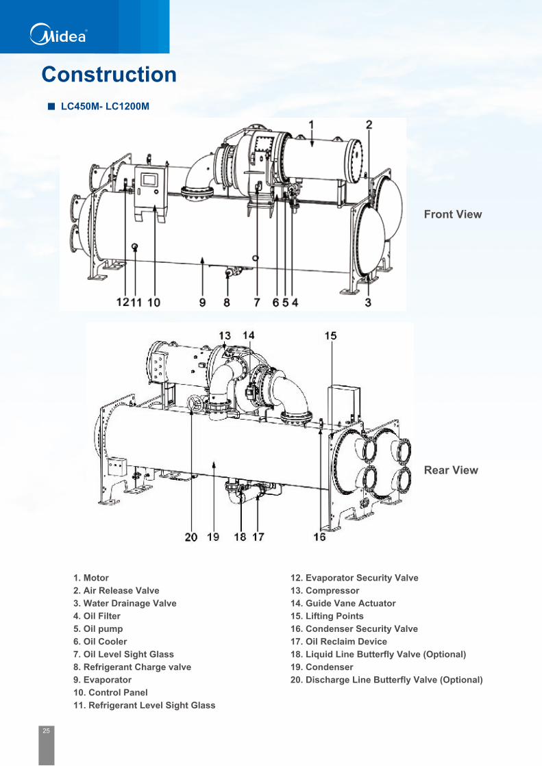
25 26
Front View
Rear View
1. Motor 2. Air Release Valve 3. Water Drainage Valve 4. Oil Filter5. Oil pump 6. Oil Cooler7. Oil Level Sight Glass8. Refrigerant Charge valve9. Evaporator 10. Control Panel11. Refrigerant Level Sight Glass
12. Evaporator Security Valve 13. Compressor 14. Guide Vane Actuator 15. Lifting Points16. Condenser Security Valve 17. Oil Reclaim Device18. Liquid Line Butterfly Valve (Optional)19. Condenser20. Discharge Line Butterfly Valve (Optional)
Front View
Rear View
1. Water outlet/inlet temperature sensor2. Security Valve3. Guide Vane Actuator4. Compressor5. Oil level Sight Glass6. Motor7. Air Release Valve
1 3
11 12
4 5 6
8
14
9
13
10 7
2
8. Water Drainage Valve9. Evaporator10. Control Panel11. Motor Connection Box12. Economizer13. Condenser 14. Electric Valve
ConstructionLC450M- LC1200M LC12000MS- LC2200MS

27 28
Service Space
Service space for stardard efficiency
Service space for high efficiency
Model
LC450M~LC750M
LC800M~LC1200M
LC1200MS~LC1800MS
LC1900MS~LC2200MS
M
1100
1500
1500
1500
T
4200
4500
5300
5300
Y
1200
1300
1300
1300
S
1200
1300
1300
1300
Z
1000
1000
1000
1000
Service Space(mm)
Model
LC650H~LC1100H
LC1200HS~LC1400HS
LC1700HS~LC2200HS
M
1500
1600
1600
T
4500
4800
5000
Y
1300
1300
1300
S
1300
1800
1800
Z
1000
1000
1000
Service Space(mm)
Insulation
Note: The gray area need to be insulated. Normally the chiller is insulated in the factory. If the chiller has to be insulated in the jobsite, it must ensure that:• Moveable components and parts shouldn’t be affected by insulation.• Please don’t leave connecting bolt in insulation.• Please don’t leave name plate in insulation.• Please open water box cover when clean the evaporator tubes.
Note: The size "T" stands for the dimension to pull out the coper tube from the heat exchanger.It can be done from both sides.
Insulation will be elastomeric foam of Class ‘O’ in accordance with BS 476 either factory or field-installed suitable to prevent sweating in environments with RH 85 % & dry bulb temperature ranging from 18 °C to 35°C.The properties of the elastomeric foam shall be as follows:CFC free closed cell nitrile rubber & noncombustible material. Density: 65-75 kg/m3. Thermal conductivity: Maximum 0.04 W/mK at a mean temperature of 20°C. Maximum & minimum service temperature: 105°C & 0°C. Water vapor permeability: 0.13 ugm/Nh.Moisture absorption: Less than 2.5 percent by volume.
The insulation will cover all low temperature surfaces to include the evaporator, water boxes, oil return lines, chilled water flow switch piping, condenser bottom portion (if sweats during shutdown) and compressor suction line to the satisfaction of the Owner. Final color of the insulation shall match the chiller body not insulated to provide a homogenous color tone.

29 22
Microprocessor Control
Refrigeration CycleRefrigeration systemMidea LC centrifugal chiller is the steam-compressing cycle type. The refrigerant will be imposed vertical energy by the high speed impeller to increase its temperature and pressure. The high pressure and temperature refrigerant gas will release its thermal energy to the cooling water in condenser, thus decrease its temperature. After throttled by the orifice its pressure will be decreased dramatically. In evaporator the low temperature and low pressure refrigerant will absorb the thermal energy from the chilled water to evaporating. The low temperature chilled water produced in this refrigeration circulation. One refrigeration circulation includes four indispensable processes: compressing, condensing, throttling and evaporating.

31 32
Basic Indication ItemsChilled water inlet temperatureChilled water outlet temperatureCooling water inlet temperatureCooling water outlet temperatureCondensing pressureEvaporating pressureOil supply temperatureOil supply pressureOil sump temperatureOil sump pressureOil supply pressure differenceInlet guide vane openingRunning current (percentage)Total power on timeTotal running timeTotal start-up time
Capacity ControlMinimum IGV opening controlMaximum main motor current controlLeaving chilled water temperature controlInlet guide vane actuator Manual mode option
User SettingsRestart temperaturePause temperatureCurrent limitFull load/rated loadChilled water outlet temperatureRated motor currencySystem control modeLow oil supply pressure difference (before start)Low oil supply pressure difference (after start)Minimum oil supply pressure difference.Minimum oil sump temperatureHigh oil supply temperatureMaximum oil supply temperatureLow evaporation pressureMinimum evaporation pressureHigh condensing temperature Maximum condensing temperature Low chilled water outlet temperatureCritical inlet guide vane openingCritical water temperature Note:Setting values refer to user manual
Safety CutoutsThe all protection control, if necessary, shuts the chiller off or limits the open of inlet guide van to protect the chiller from possible damage.
Inadequate oil supply pressure difference.Excessive oil supply temperatureInadequate oil sump temperatureOil pump current overloadInadequate chilled water flow Low chilled water outlet temperatureCompressor motor current overload Excessive main motor winding temperatureExcessive Start time Inadequate evaporation pressureExcessive condensing pressure Temperature transmitter faultsPressure transmitter faultsStarter faultsPhase unbalance, phase loss, phase reversalUnder voltageOver voltage
User-friendly Interface● The Microprocessor-based control system is equipped with an MODBUS-RTU port or other optional protocols that offers multiple remote control, monitoring and diagnostic possibilities. It provides a platform to display the real time information and self-control the entire system. It also integrates the logical program such as pre-alarm, safety protection, interlock control etc., which ensures the system’s proper start/start, normal operation and energy saving pause operation.● The unit controller is factory mounted, wired and tested before shipment, to ensure machine operation in a proper condition.
Interface Display
Graphical display
Touch screen
Operation status
Operation Parameters
Pre-alarm/alarm
indication and record
Enquiry function for historical
data and trend curve
Pause function reduces
the operation cost
Independent start/stop control
Set outlet temperature by users
Automatically load or unload according
to the chilled water temperature
Operation Control
Interlock Control
Oil pump pre-lubrication/ post-lubrication
Water pump pre-running/ post-running
Starter interlock control
Pause/Stop mode Inlet Guide Vane interlock
Pause/stop mode inlet guide
vane interlock
Safety testing before start
Pre-alarm interlock control
Safety Protection
Oil pressure difference low/too low
Oil temp. High & too high
Compressor motor ampere high & too high
Compressor motor ampere too low
Evaporator pressure low/too low(Evaporator)
Refrigerant pressure high/too high (Condenser)
Oil pump overload
Starter fault
Long time starting
Water cut off in
evaporator or condenser
Anti-freezing protection

33 34
Standard Protection
Low Supply Oil-pressure Difference ProtectionOil pressure is indication of oil flow and oil-pump operation. A significant drop in oil pressure difference indicates a failure of the oil pump, oil leakage, or other blockage in the oil-circuit. The differential pressure during compressor pre-lube mode should not fall below set point. A failure on meets this requirement leads to inhibit the start of the chiller. When the compressor is running, an alarm will be displayed if the differential pressure is below set point. And if this value decreases to the minimum set point the chiller will shut-down.
Oil-Temperature ProtectionHigh oil temperature when the oil pump and/or compressor are running may be an indication of oil-cooler failure, overheating of the oil and the bearings, or oil filter blockage. If the oil temperature continuous increase to the maximum set point, the chiller will shut-down. The start of the compressor will be inhibited if the oil sump temperature is below the set point. The diagnostic will display at the user interface.
Oil Pump Current Overload ProtectionThe oil pump control panel will monitor the current of oil pump, and shut the chiller off when the oil pump current exceeds its maximum set point.
High Condenser-Pressure Protection The chiller controller’s algorithm keeps the condenser pressure under a specified maximum pressure. The chiller can run up to 100 percent of this setpoint in a safe and reliable condition. If the condenser pressure exceeds the set point, the system will prohibit the open of the inlet guide vane to decrease the pressure or shut off the chiller immediately according to the different set point.
Low Evaporator-Pressure Protection The chiller controller’s algorithm keeps the evaporator pressure under a specified minimum pressure. The chiller can run up to 100 percent of this setpoint in a safe and reliable status.If the evaporator pressure decreases below the set point, the system will prohibit the open of the inlet guide vane to increase the pressure or shut off the chiller immediately according to the different set point.
Water Flow ProtectionThe water flow switches is required to install in the water piping system. The chiller controller has a digital input that will indicate the water flow. When this input does not prove flow within a fixed time during the starting, the process will be terminated. If the flow is lost while the chiller is in running, the system will shut the chiller off to protect the chiller from possible damage.
Current Overload ProtectionThe control panel will monitor the current drawn by each line of the motor and if the highest of the three line currents exceeds 110% of the rated current, the system will close the inlet guide vane automatically and check whether the current decrease to normal condition. And the system will shut the chiller off if the highest of the three line currents exceeds 115% of the rated current. The current overload protection does not prohibit the chiller from reaching its full-load ampere.
High Motor-Winding Temperature ProtectionThis function monitors the motor temperature and terminates chiller operation when the temperature is excessive. The controller monitors the winding-temperature sensors any time the controller is energized. And immediately shut the chiller off if the temperature surpasses the maximum set point.
Start Time Limit ProtectionWhen start the chiller, if the time from Wye connection change to Delta connection exceeds set point. The system will shut the chiller off immediately to protect the chiller from possible damage.
Power Supply ProtectionA factory installed transformer or power supply protection module in the starter, if any overvoltage or undervoltage, phase-unbalance, phase-loss, phase reversal happens, the control system will detect it and shut the chiller off in time.
Low Chilled Water Outlet Temperature ProtectionLow chilled water outlet temperature protection, also known as anti-freeze protection, avoids water freezing in the evaporator by immediately pause the chiller if the chilled water outlet temperature reaches its minimum allowable value. After the chilled water inlet temperature reach the restart set point, the chiller will start automatically. This protection may be due to the sensor fault, incorrect set point of chilled water outlet temperature or lack of chilled water flow.
Starter Failure ProtectionThe chiller will protect itself from a starter failure,that ensures the compressor motor disconnecting from the line when the motor reach the limits of its capabilities. The controller starts and stops the chiller through the starter. If the starter malfunctions and does not disconnect the compressor motor from the line in an emergency situation, the controller will recognize the fault and shut the chiller off immediately.

35 36
Centralized Control Typical Wiring DiagramIntelligent Control Logic Ensures System Reliability
Advanced Control Room & Centralized Controls
Centralized Control and Remote Management
By monitoring all the parameters such as chilled water outlet temp., setting temp., evaporating pressure, condensing pressure and inlet guide vane opening degree, etc., the intelligent control logic decides the best load adjustment method and optimizes the frequency of motor and the opening rate of inlet guide vane to guarantee the safe operation in various load conditions.
The conventional BMS system only focuses on the interlock control, operation status and parameter monitor, which is capable to achieve automation and energy management, but it neglects the optimization of equipment matching and controlling. Midea centralized energy management system attaches importance on building load prediction and control, and coordinates the operation of air-conditioner, fan and water pumps to realize the optimum energy management.
System Control Functions:
Energy management:
● Pragmatic Control ModesVarious and auto control, remote and local control, etc.● Equalized operation time:Automatically balance the operation time of each unit to extend the life-span and minimize the maintenance● Optimum operation schedule:Optimizes the operation schedule and qty. of water pumps, to minimize the total system power consumption. ● System data report:It reports the operation capacity, power consumption and energy saving effect, as well the malfunction record and historical operation record. ● Strategies to address problemsSystem status indication and pre-alarm/alarm functions ensure the safety. Complete event management provides operator convenience to check historical records.● Remote communication functionAdoption of the public open protocol enables the data exchange between the onsite energy management centre and the upper remote monitoring system and remote operation, maintenance and management.
● Climatic feedback control: Collect outdoor temperature and accordingly adjust the water volume when climate changes, thus reducing the energy consumption.● Cycle duty operation: Supply different capacity according to specific application in each building● Load prediction control: Due to perspective control logic, it decreases the frequency of startup and shutdown and minimizes the impact to the power grid, therefore extending the life span and reducing power consumption.
Corporate Energy
Management Platform
Air compressor Chiller Boiler Fan Pump
Energy Management SystemEnergy Intelligent Building Management Automation System
Energy Intelligent Control System
Controller layerEnergy Control Centre
Energy Control UnitEnergy Control Terminal
Device layerIndustrial Equipment
HVAC, Lighting, ElevatorsFans, Valves, Pumps
Sensors
Corporate level management layer
System management layer
BMS SYSTEM
Midea Chiller Central Controller
Touchable Screen
Central Controller
Centrifugal Chiller
Centrifugal Chiller
Screw Water Chiller
Pressure difference sensor
Temperature sensor
Water flow meter
Electrical operated valve
Chilling water pump
Chilled water pump
Cooling tower
Electricity panel
Low voltage (Closed star-delta connection)
High voltage (Direct on line connection)
KM2
KM1
KM3
U1
KM4
R
QF1
V1 W1
W2 U2 V2
L1 L2L3 N PE
UI VI WI W2 U2 V2
L1L2L3N
PE
AC380V 3PH 50Hz
AC380V 3PH 50Hz
M3~
Unit Control Box
Y-△Starter
11 12 1713 14 15 16
12345
UNIT RUNNINGUNIT FAULT
UNIT CURRENT
MAIN SWITCH ON
COM
UNIT
RUNN
ING
UNIT
FAU
LT
UNIT C
URRE
NT
MAIN
SWITC
H ON
COM
2FU F
TAL
DXN
TAu~w
1FU
QF
QK
V
V
LN
L1L2L3PE
U V W
AC10KV 3PH 50Hz
L1L2L3NPE
AC380V 3PH 50Hz10KV Directly Starter
M
3~
Unit Control Box
AC 220V/50Hz
Matching
11 12 1713 14 15 16
12345
1918 Matching
UNIT RUNNINGUNIT FAULT
UNIT CURRENT
MAIN SWITCH ON
COM
UNIT SWITCH OFF
UNIT
RUNN
INGUN
IT FA
ULT
UNIT
CURR
ENT
MAIN
SWITC
H ON
COM
UNIT
SWITC
H OFF
Note:The wiring diagram for reference only.

37 38
Electrical control panel wiring diagram
Closed star-delta starting cabinet High voltage start cabinet Starting cabinet space layout
Back viewFront view
W(1000)xD(800)xH(2200)
Side view
2200
8001000
电压 电流
电源
电压转换
启动 运行
电流转换
1000
1500
1000
1000
1500
1000
箱型固定式金属封闭开关设备(环网柜)
额定雷电冲击耐受电压
出 厂 编 号额定短时耐受电流
XXXXXXXX 制 造 日 期
kVXXXX kAXXXX
额定短路持续时间XXXX额定短时工频耐受电压
s
额 定 电 压额 定 电 流
kVXXXX AXXXX
额 定 频 率 XXXX符 合 标 准 GB3906
HzXXXXkV
产 品 型 号 HXGN□-12 并 列 号 G1
VV
合
分
合
分
接地开关
负荷开关
分
合
Closed star-delta starting cabinet maintenance,
operation plane spacing
High pressure direct starting cabinet maintenance,
operation plane spacing
福建东方电器有限公司
关柜门将操作杆插入接地开关操作孔内,转动至接地开关分将操作杆插入负荷开关操作孔内,转动至负荷开关合闸
将操作杆插入负荷开关操作孔内,转动至负荷开关分闸,并使复位机构回到最低位置将操作杆插入接地开关操作孔内,转动至接地开关合打开柜门
说明:对熔断器撞击器或分励线圈触发脱扣使负荷开关分闸 ,需用操
作杆插入负荷开关操作孔内,转动至分闸位,并使复位机构回到最低位置后,才能进行合闸操作。
88888888
送电: 停电:
福建东方电器有限公司
关柜门将操作杆插入接地开关操作孔内,转动至接地开关分将操作杆插入负荷开关操作孔内,转动至负荷开关合闸
将操作杆插入负荷开关操作孔内,转动至负荷开关分闸,并使复位机构回到最低位置将操作杆插入接地开关操作孔内,转动至接地开关合打开柜门
说明:对熔断器撞击器或分励线圈触发脱扣使负荷开关分闸 ,需用操作杆插入负荷开关操作孔内,转动至分闸位,并使复位机构回到最低位置后,才能进行合闸操作。
箱型固定式金属封闭开关设备(环网柜)
额定雷电冲击耐受电压
出 厂 编 号额定短时耐受电流
XXXXXXXX 制 造 日 期
kVXXXX kAXXXX
额定短路持续时间 XXXX额定短时工频耐受电压
s
额 定 电 压额 定 电 流
kVXXXX AXXXX
额 定 频 率 XXXX符 合 标 准 GB3906
HzXXXX kV
产 品 型 号 HXGN□-12 并 列 号 G1
V
V
合
分
合
分
接地开关
负荷开关
分
合
JZC5-12J390X160
Side view Back view Front view
1100 1100
2200
88888888
送电: 停电:
Starter Cabinet Dimensions
Recommended Copper Size
101 105 514 516 21 204 206 N'L1.5 113 115 510 32125 127 117 119 N'
X
X2
PCS
1 2 3 4 5 6 7 8 9 10 11 12 17 18 19 20 21 22 23 24
1M
COMPRESSOR MOTER
STARTER
UN
IT R
UN
NIN
G
UN
IT F
AU
LT
UN
IT C
UR
RE
NT
MA
IN S
WIT
CH
ON
VANE ELECTRIC ACTUATOR
POWER SUPPLY
25 26 27
N L O C + -
13 14 15 16
CO
M
UNIT
SWITC
H OF
F(SPA
RE)
PENL3L2L1
POWER SUPPLY380V-3N-50HZ 5KVA
2M
OIL PUMP
EH
1
OLIHEATER
U V W L2.4 N
HOT GAS SOLENOID
28 29 30
CO COM
VAN
PO
SIT
ION
CLO
SE
OP
EN
PO
WE
R S
UP
PLY
502 504 31 506 508 402 404 406 408 410 412 414 416 418 420 422 424 426 428 21 210 21431 31 31 212 216 21821 21 21 21 22021
PCS
SP3SP1 SP2
OIL
TA
NK
PR
ES
PI
PI
PI
PI
EVA
P P
RE
S
CO
ND
EN
SO
R P
RE
S
OIL
SU
PP
LY P
RE
S
CH
ILLE
D W
ATE
R O
FF
EVA
P W
ATE
R O
FF
WIN
DIN
G O
VW
EH
EAT
INTE
R L
OC
K S
TOP
SP4
CH
ILLE
D W
ET
CH
ILLE
D W
LT
CO
OLI
NG
WE
T
CO
OLI
NG
WLT
OIL
SU
PP
LY T
EM
P
EX
HA
US
T TE
MP
OIL
TA
NK
TE
MP
RTD1 RTD2 RTD3 RTD4 RTD5 RTD6 RTD7 SQ1 SQ2 BT1 SB1 SB2
RE
MO
TE S
TOP
SB3
RE
MO
TE S
TAR
T
θ
222 224 226 107 109 111 N' 319 321 323 22 325 22 327 22 329 PE PE PE21 21 21 N' N' PE PE129 PE
USER BACKUP
PCS
72 73 74 75 76 77 78 79 80 81 82 83 84 85 86 87 88
CO
OLI
NG
TO
WE
R
CO
OLI
NG
PU
MP
89 90 91
ALA
RM
CH
ILLE
D P
UM
P
92
ALA
RM
STO
P
com
93 PE
SPA
RE
RU
NN
ING
PEPEPEPEPE
SPA
RE
SPA
RE
SPA
RE
SPA
RE
SPA
RE
Note: The recommended copper cable size is suitable for the single phase from the same supplier and same standard. It may be slightly change due to the ambient temperature and surroundings.
High voltage
61.3
61.3
70.1
70.1
78.8
78.8
87.0
87.0
95.1
105.1
105.1
125.3
125.3
139.2
139.2
105.1
109.5
121.4
133.9
146.4
155.6
161.4
YJV22-35
YJV22-35
YJV22-50
YJV22-50
YJV22-50
YJV22-50
YJV22-50
YJV22-50
YJV22-70
YJV22-70
YJV22-70
YJV22-70
YJV22-70
YJV22-95
YJV22-95
YJV22-70
YJV22-70
YJV22-70
YJV22-70
YJV22-95
YJV22-95
YJV22-95
37.2
37.2
42.5
42.5
47.9
47.9
52.8
52.8
57.4
63.8
63.8
75.2
75.2
83.5
83.5
62.4
65.0
72.2
79.5
87.7
93.4
96.6
YJV22-25
YJV22-25
YJV22-35
YJV22-35
YJV22-35
YJV22-35
YJV22-35
YJV22-35
YJV22-50
YJV22-50
YJV22-50
YJV22-50
YJV22-50
YJV22-70
YJV22-70
YJV22-50
YJV22-50
YJV22-50
YJV22-50
YJV22-70
YJV22-70
YJV22-70
Max Ampere(10000V)6000V 10000VMax Ampere
(6000V)
LC650M(H)
LC700M(H)
LC750M(H)
LC800M(H)
LC850M(H)
LC900M(H)
LC950M(H)
LC1000M(H)
LC1100M(H)
LC1200M(H)
LC1300M(H)
LC1400M(H)
LC1500M(H)
LC1600M(H)
LC1700M(H)
LC1200M(H)S
LC1350M(H)S
LC1500M(H)S
LC1650M(H)S
LC1800M(H)S
LC1900M(H)S
LC2000M(H)S
Model
2xBVR240
2xBVR240
2xBVR240
2xBVR300
2xBVR300
2xBVR300
3xBVR240
3xBVR240
3xBVR240
3xBVR240
3xBVR300
3xBVR300
4xBVR240
4xBVR240
4xBVR240
low voltage
LC650M(H)
LC700M(H)
LC750M(H)
LC800M(H)
LC850M(H)
LC900M(H)
LC950M(H)
LC1000M(H)
LC1100M(H)
LC1200M(H)
LC1300M(H)
770
770
770
890
974
974
1113
1113
1252
1252
1382
1382
1502
1670
1670
2xBVR240
2xBVR240
2xBVR240
2xBVR300
2xBVR300
2xBVR300
3xBVR240
3xBVR240
3xBVR240
3xBVR240
3xBVR300
3xBVR300
4xBVR240
4xBVR240
4xBVR240
BVR300
BVR300
BVR300
2xBVR120
2xBVR150
2xBVR150
2xBVR185
2xBVR185
2xBVR240
2xBVR240
2xBVR240
2xBVR240
2xBVR300
2xBVR300
2xBVR300
MaxCurrent
Y-△Cable in
Y-△Cable out
Auto-transformer in/outModel
LC450M
LC500M
LC550M
LC600M31 32 33 34 35 36 37 38 39 40 41 42 43 44 45 46 47 48 49 50 51 52 53 54 55 56 57 58 59 60 61 62 63 64 66 6765 68 69 70 71

39 40
Typical Piping and Cable Layout
Choose the proper power supply cable size and tag clearly.
Filter must be used in the water system.
Thermometer and pressure meter must be installed in the water system.
Recommend to use a steel pipe to connect the security release valve to the outside.
Recommend to use an oxygen density indicator that alarm automatically when the density lower than 19.5%.
Cable and pipe layout should be done based on local regulation.
Mechanical Specification
CompressorThe centrifugal compressor with high-strength aluminum alloy fully shrouded impellers and moveable inlet guide vane. The enclosed type impeller is designed for balanced thrust and is dynamically balanced and overspeed tested for smooth, vibration free operation. Airfoil shaped inlet guide vane minimize flow disruption for the most efficient part load performance.The movement of the inlet guide vane is controlled by a mounted electric actuator in response to refrigeration load on the evaporator. The rotor assembly consists of a heat-treated alloy steel drive shaft with a high strength, and the high speed shaft is forged with high strength and reliability.
MotorMidea centrifugal chiller use semi-hermetic two-pole motor and is cooled by the circular refrigerant, winding embedded sensors provide positive thermal protection to the motor. Asynchronism squirrel cage type motor can achieve higher operation performance and longer life span. Refrigerant cooled motor keeps motor heat out of the mechanical room, decrease vibration and shaft seal maintenance compare with open motors. Also refrigerant cooled motor have lower inrush currents and lower noise than open motor which cooled by air, there is no need to provide additional ventilation or air conditioning for the mechanical room than open motor design. The motor is bolt connected to the compressor gear housing and shaft labyrinth seal prevents refrigerant leakage from the motor to the gear box. Low voltage motor provides 6 terminals for reduce starting voltage (wye-delta or auto transformer start). High voltage motor provides three terminal posts for full voltage (across the line). Motor terminal pads are supplied. A moveable steel sheet terminal box encloses the terminal board area to insulation.
Impeller And Inlet Guide VaneHigh s t reng th a luminum-a l loy compressor impe l le rs fea tu re backward-curved vanes for high efficiency Airfoil shaped inlet guide vane minimize flow disruption for the most efficient part load performance. Precisely positioned and tightly fitted, it allows the compressor to unload smoothly from 10% to 100% load output for excellent operation in real air conditioning application. The movement is controlled by a mounted electrical operator in response to refrigeration load on the evaporator. Impeller is made of high strength aluminum alloy which is tested at 125% design operating speed.

41 42
Heat Exchanger TubeHeat exchanger tubes are high-efficiency, externally and internally enhanced type to provide optimum performance. Tubes in both the evaporator and condenser are 3/4" O.D. copper alloy providing an internal and external surface. This provides extra wall thickness (up to twice as thick) and non-work hardened copper at the support location, extending the life span of the heat exchanger. Each tube is roller expanded into the tube sheets providing a leakproof seal, and is individually replaceable. Copper alloy material as a standard choice and 90/10 copper-nickel, 304stainless steel or titanium material can be customized.
EvaporatorThe evaporator is a shell and tube type heat exchanger. A flow equalizer provides uniform distribution of refrigerant over the entire tube length to yield optimum heat transfer. The evaporator shell contains a dual refrigerant relief valve arrangement set at 185 PSIG (1280 kPa) or single-relief valve arrangement. Intermediate tube support sheets positioned along the shell axis prevent relative tube motion. The waterside is hydraulic tested at 1.5 times of the maximum working pressure.
CondenserThe condenser is shell and tube type, with discharge gas baffle to prevent direct high velocity gas impingement on the tubes. The baffle is also used to distribute the refrigerant gas flow properly for most efficient heat transfer. An integral sub-cooler is located at the bottom of the condenser shell providing highly effective liquid refrigerant subcooling to provide the highest cycle efficiency. Regarding the duel-stage compressing, using the economizer can improve the efficiency by 5-8%. The condenser contains a refrigerant relief valve sets at 1.6 MPa. Standard maximum waterside working pressure is 1.0 MPa. The waterside is hydraulic tested at 1.5 times of maximum working pressure.
Water BoxThe removable water boxes are fabricated of steel. The design working pressure is 150 PSIG (1034 kPa) and the boxes are tested at 225 PSIG (1551 kPa). Integral steel water baffles are located and welded within the water box to provide the required pass arrangements. The nozzle connections are suitable for flanges and are capped when shipment. Plugged 3/4" drain and vent connections are provided in each water box.
Orifice There are three refrigerant control devices used in the industry, expansion valves, fixed orifices, and float systems. Midea standard efficiency uses the fixed orifice without any move part and the reliability is high. The high efficiency and super high efficiency type centrifugal chiller equipped the orifice as well as electronic ball valve plus the liquid level control technology to improve the efficiency in the partial load. These matches ensure the chiller working in stable in any working situation and improve the IPLV and NPLV significantly.
Control PanelMidea adopts the state-of-the-art microprocessor control system with 10.4 inch LCD touchable screen and high disturbance resistance. The LCD touchable screen with graphical display of chiller parameters, fast and easy to access makes the operation relatively simple. It also can communicate with the user's PC and carry out the remote control for start, operation and stop of the cooling system. More than 30 item protections and malfunctions used to make the chiller operation secure and reliable. The latest 10 items of failure information can be recorded for inquiry.
Lubrication System A separately driven electric oil pump assembly suppl ies lube to the compressor at proper temperature and pressure .After filtration the lube been pressed to the oil cooler to cooling it to certain temperature. And then adjust its pressure before transmitted to bearings. Special designed seals are installed at inner side of motor bearings at both ends to minimize the lube that leaked into the main motor and mixed into the R134a in
evaporator. Besides, electric heater is used inside the oil tank to maintain the oil in proper temperature all the time. In this way, when the compressor shuts down, certain oil temperature can be maintained. Thus prevent the R134a gas from entering the oil to decrease the efficiency of lubrication. Therefore, while the compressor is shut down, it is necessary to keep oil heater on to make the oil temperature in certain temperature. If the compressor will out of service for a long time, it is required to run the oil heater to maintain the proper oil temperature.
Evaporator Condenser

43 44
Selection SoftwareFor optimize the configuration and performance of Midea product, as well as to match the actual requirements of your HVAC system.This independent software can select the best components configuration according to the requirement of your HVAC system. After input the general parameters such as cooling capacity, fouling factor, pass number, power supply, etc. Nominal data and physical data for typical compressor-evaporator - condenser combinations are given by product list. Midea R&D fellow and software engineers will update the improvement information of the product online in time, and our customer can get the update information through the internet.
60Hz is optinal
50Hz is standard and 60Hz is also available.
Water inlet/outlet connection
Flange type connection is the standard for the condenser and evaporator. Victaulic type connection is optional.
High pressure water box
Standard water box can sustain 1.0Mpa pressure .1.6Mpa or 2.0Mpa pressure is optional.
Marine water box
The condenser and evaporator can be provided with marine water box on the water connection side which provides
easy access to the tube for inspection, clearing and remove without disturbing the water pipe connection.
Pass
The standard chiller is 2 passes. 1 pass or 3 passes are optional.
VSD (Variable speed drive)
Capacity less than 1300Ton product can be equipped with VSD for super high efficiency partial load.
Chiller starter
Delta star is a standard starter witch provided with the chiller. Auto transmit starter is another option for the low
voltage chiller. Softer starter also can be provided to reduce the rush to the power supply net. Direct on line (DOL)
is optional for the high voltage chiller (3000-11000V).
Chiller sequence management (Chiller Plant Manager)
Chiller plant manager can be provided to the multiple installations for control & monitor low side work.
Chiller vibration isolator
Spring isolator and rubber pad are the optional accessories from the factory
Dual compressor
Dual compressor system can be provided to the big capacity or strong back up for the chiller system.
Sectional transportation
The chiller can be part transport to the site and reassembling on the site under Midea engineer’s inspection.
Witness performance testing
Factory provide the witness testing service for the clients
Optional items / Accessories
Selection interface
Selection report
Centrifugal Chiller Specification Project Name: New Project Tag Name: 1000TR Certified in accordance with the latest edition of the AHRI
standards 550/590(I-P) and 551/591(SI) for Water-Chilling
Packages using the Vapor Compression Cycle. Chiller Model ------------------------- CCWE1000H Stage Number --------------------------------------- 1 Compressor Size ------------------------------ H402 Oil Model ----------------------------------------- POE Refrigerant Charge --------------------------- 774 kg Oil Charge ------------------------------------- 78.4 kg Shipping Weight --------------------------- 11320 kg Motor Size --------------------- EKDS-630K-2-c541 Running Weight -------------------------- 14192.4 kg Motor Efficiency ------------------------------- 0.955 Length ---------------------------------------- 5045 mm Starting Power Voltage ----------- 380V-3P+N+PE Width ----------------------------------------- 2300 mm Control Power Voltage ------------ 380V-3P+N+PE Height ---------------------------------------- 2610 mm Starting Equipment ---------- Wye-Delta Starter /
Freestanding Acoustic Data ---------------------------------- 88 dBA Starter Code ------------------- QSFME54(740)(JB) Capacity -------------------------------------- 3517 kW Full Load Power Input ---------------------- 599 kW Full Load Efficiency ---------------- 5.8703 kW/kW IPLV / NPLV ------------------------ 6.3684 kW/kW
0.1703 ikW/kW 0.157 ikW/kW Entering Temperature ----------------------- 12.2 °C Size ------------------------------------------------- Z46N Leaving Temperature -------------------- 6.6667 °C Tubing ---------- Midea EI-1in, 0.635mm, Cooper Flow Rate --------------------------------- 151.416 L/s Passes -------------------------------------------------- 2 Brine-side Pressure Drop -------------- 52.715 kPa Waterboxes -------------- Nozzle-in-Head / 1 MPa Fouling Factor ------------------ 0.000018 m²-K/W Fluid Type ------------------------------- Fresh Water Concentration ---------------------------------- 0.00% Entering Temperature --------------------- 29.44 °C Size ------------------------------------------------ N46N Leaving Temperature ------------------- 34.6029 °C Tubing ---------- Midea CI-1in, 0.635mm, Cooper Flow Rate --------------------------------- 189.271 L/s Passes -------------------------------------------------- 2 Brine-side Pressure Drop -------------- 47.758 kPa Waterboxes -------------- Nozzle-in-Head / 1 MPa Fouling Factor ------------------ 0.000044 m²-K/W Fluid Type ------------------------------- Fresh Water Concentration ---------------------------------- 0.00% FLA -------------------------------------------- 1034.3 A LRA ----------------------------------------------- 7625 A Max. Running Current ----------------------- 1252 A
Unit Information
Performance Information
Cooler Information
Condenser Information
Electrical Information
Centrifugal Chiller Configuration Project Name: New Project Tag Name: 1000TR Refrigerant Shipment -------- Shipped Separately Stop Valve ------------------------------ Not Installed Oil Shipment ------------------- Shipped Separately Hot Gas Bypass ------------------------ Not Installed Insulation --------------- Factory Insulation 20 mm -------------------------------------------- Not Installed Motor Protection -------------------------------- IP54 -------------------------------------------- Not Installed Packaging Options ----------- Fumigation Package Cooler Nozzle Arrangements ----------- Compressor End Connection ----------------------------------- Flanged Condenser Nozzle Arrangements ----------- Compressor End Connection ----------------------------------- Flanged Compressor Silencer ----------------- Not Installed Discharge Line Sound Reduction Kit ---------- Not
Installed Condenser Sound Reduction Kit -- Not Installed Communication -------------------------------- RS485 PLC ------------------------------------------- Schneider Protocol --------------------------------- Modbus RTU Switch Gear Brand --------------------------- Default Screen Size ---------------------------------------- 10 in Power Line Arrangement ---- Top in Bottom out
General
Waterboxes
Sound
Electrical

Conversion table
Celsius
39.0
40.0
41.0
42.0
43.0
44.0
45.0
46.0
47.0
48.0
49.0
50.0
51.0
52.0
53.0
54.0
55.0
56.0
57.0
58.0
59.0
60.0
61.0
62.0
63.0
64.0
65.0
66.0
67.0
68.0
69.0
70.0
71.0
72.0
Fahrenheit
102.2
104.0
105.8
107.6
109.4
111.2
113.0
114.8
116.6
118.4
120.2
122.0
123.8
125.6
127.4
129.2
131.0
132.8
134.6
136.4
138.2
140.0
141.8
143.6
145.4
147.2
149.0
150.8
152.6
154.4
156.2
158.0
159.8
161.6
Celsius
5.0
6.0
7.0
8.0
9.0
10.0
11.0
12.0
13.0
14.0
15.0
16.0
17.0
18.0
19.0
20.0
21.0
22.0
23.0
24.0
25.0
26.0
27.0
28.0
29.0
30.0
31.0
32.0
33.0
34.0
35.0
36.0
37.0
38.0
Fahrenheit
41.0
42.8
44.6
46.4
48.2
50.0
51.8
53.6
55.4
57.2
59.0
60.8
62.6
64.4
66.2
68.0
69.8
71.6
73.4
75.2
77.0
78.8
80.6
82.4
84.2
86.0
87.8
89.6
91.4
93.2
95.0
96.8
98.6
100.4
Celsius
-29.0
-28.0
-27.0
-26.0
-25.0
-24.0
-23.0
-22.0
-21.0
-20.0
-19.0
-18.0
-17.0
-16.0
-15.0
-14.0
-13.0
-12.0
-11.0
-10.0
-9.0
-8.0
-7.0
-6.0
-5.0
-4.0
-3.0
-2.0
-1.0
0.0
1.0
2.0
3.0
4.0
Fahrenheit
-20.2
-18.4
-16.6
-14.8
-13.0
-11.2
-9.4
-7.6
-5.8
-4.0
-2.2
-0.4
1.4
3.2
5.0
6.8
8.6
10.4
12.2
14.0
15.8
17.6
19.4
21.2
23.0
24.8
26.6
28.4
30.2
32.0
33.8
35.6
37.4
39.2
Formulas: C = (F - 32) × 5 / 9, F = (C × 9 / 5) + 32
Temperature:℉—℃
PSI
1.0
2.0
3.0
4.0
5.0
6.0
7.0
8.0
9.0
10.0
11.0
12.0
13.0
14.0
15.0
16.0
17.0
18.0
19.0
20.0
21.0
22.0
23.0
24.0
25.0
26.0
27.0
28.0
29.0
30.0
31.0
32.0
33.0
34.0
35.0
36.0
37.0
38.0
39.0
40.0
kPa
6.89
13.79
20.68
27.58
34.47
41.37
48.26
55.16
62.05
68.95
75.84
82.74
89.63
96.53
103.42
110.32
117.21
124.11
131.00
137.90
144.79
151.68
158.58
165.47
172.37
179.26
186.16
193.05
199.95
206.84
213.74
220.63
227.53
234.42
241.32
248.21
255.11
262.00
268.90
275.79
kg/m2
0.07
0.14
0.21
0.28
0.35
0.42
0.49
0.56
0.63
0.70
0.77
0.84
0.91
0.98
1.05
1.12
1.20
1.27
1.34
1.41
1.48
1.55
1.62
1.69
1.76
1.83
1.90
1.97
2.04
2.11
2.18
2.25
2.32
2.39
2.46
2.53
2.60
2.67
2.74
2.81
PSI
41.0
42.0
43.0
44.0
45.0
46.0
47.0
48.0
49.0
50.0
51.0
52.0
53.0
54.0
55.0
56.0
57.0
58.0
59.0
60.0
61.0
62.0
63.0
64.0
65.0
66.0
67.0
68.0
69.0
70.0
71.0
72.0
73.0
74.0
75.0
76.0
77.0
78.0
79.0
80.0
kPa
282.69
289.58
296.47
303.37
310.26
317.16
324.05
330.95
337.84
344.74
351.63
358.53
365.42
372.32
379.21
386.11
393.00
399.90
406.79
413.69
420.58
427.47
434.37
441.26
448.16
455.05
461.95
468.84
475.74
482.63
489.53
496.42
503.32
510.21
517.11
524.00
530.90
537.79
544.69
551.58
kg/m2
2.88
2.95
3.02
3.09
3.16
3.23
3.30
3.37
3.45
3.52
3.59
3.66
3.73
3.80
3.87
3.94
4.01
4.08
4.15
4.22
4.29
4.36
4.43
4.50
4.57
4.64
4.71
4.78
4.85
4.92
4.99
5.06
5.13
5.20
5.27
5.34
5.41
5.48
5.55
5.62
PSI
81.0
82.0
83.0
84.0
85.0
86.0
87.0
88.0
89.0
90.0
91.0
92.0
93.0
94.0
95.0
96.0
97.0
98.0
99.0
100.0
101.0
102.0
103.0
104.0
105.0
106.0
107.0
108.0
109.0
110.0
111.0
112.0
113.0
114.0
115.0
116.0
117.0
118.0
119.0
120.0
kPa
558.48
565.37
572.26
579.16
586.05
592.95
599.84
606.74
613.63
620.53
627.42
634.32
641.21
648.11
655.00
661.90
668.79
675.69
682.58
689.48
696.37
703.27
710.16
717.05
723.95
730.84
737.74
744.63
751.53
758.42
765.32
772.21
779.11
786.00
792.90
799.79
806.69
813.58
820.48
827.37
kg/m2
5.69
5.77
5.84
5.91
5.98
6.05
6.12
6.19
6.26
6.33
6.40
6.47
6.54
6.61
6.68
6.75
6.82
6.89
6.96
7.03
7.10
7.17
7.24
7.31
7.38
7.45
7.52
7.59
7.66
7.73
7.80
7.87
7.94
8.01
8.09
8.16
8.23
8.30
8.37
8.44
PSI
121.0
122.0
123.0
124.0
125.0
126.0
127.0
128.0
129.0
130.0
131.0
132.0
133.0
134.0
135.0
136.0
137.0
138.0
139.0
140.0
141.0
142.0
143.0
144.0
145.0
146.0
147.0
148.0
149.0
150.0
151.0
152.0
153.0
154.0
155.0
156.0
157.0
158.0
159.0
160.0
kPa
834.27
841.16
848.06
854.95
861.84
868.74
875.63
882.53
889.42
896.32
903.21
910.11
917.00
923.90
930.79
937.69
944.58
951.48
958.37
965.27
972.16
979.06
985.95
992.85
999.74
1006.63
1013.53
1020.42
1027.32
1034.21
1041.11
1048.00
1054.90
1061.79
1068.69
1075.58
1082.48
1089.37
1096.27
1103.16
kg/m2
8.51
8.58
8.65
8.72
8.79
8.86
8.93
9.00
9.07
9.14
9.21
9.28
9.35
9.42
9.49
9.56
9.63
9.70
9.77
9.84
9.91
9.98
10.05
10.12
10.19
10.26
10.34
10.41
10.48
10.55
10.62
10.69
10.76
10.83
10.90
10.97
11.04
11.11
11.18
11.25
Formulas: 1psi≈6.894757 kpa 1psi≈0.070306958kg/m2
Pressure: PSI—kPa—kg/m2
We reserve the right to make change in design and construction at any time without notice.
45 46

1503-6C1412
COMMERCIAL AIR CONDITIONERS
Commercial Air Conditioner Business UnitsMidea GroupAdd: West Region of Midea Commercial Air Conditioner Department, Industry Avenue,
Beijiao, Shunde, Foshan, Guangdong, P. R. China
Postal code: 528311
Tel: +86-757-26338346 Fax: +86-757-22390205
http://global.midea.com.cn
http://www.midea.com
Note: The data in this book may be changed without notice for further improvement
on quality and performance.
Ver.2014.12
D e a l e r i n f o r m a t i o n
Water Cooled Centrifugal Chillerstandard efficiency:450-2200TonHigh efficiency:650-2200TonR134a