15 Terna TM - Lighting New York Terna.… · 15" Terna TM Fig. 14 Fig. 13 Safety Cable Bolt Wood...
14
Kichler ® Lighting 7711 East Pleasant Valley Road P.O. Box 318010 Cleveland, Ohio 44131-8010 Customer Service 866.558.5706 8:30 AM to 5:00 PM EST, Monday - Friday Instruction Manual 15" Terna TM A Kichler ® Decor ™ ceiling fan 300215 3066708 Includes our new CoolTouch Control System Looks permanent, but goes wherever you go! U.S. Patent Pending TM
Transcript of 15 Terna TM - Lighting New York Terna.… · 15" Terna TM Fig. 14 Fig. 13 Safety Cable Bolt Wood...
Kichler® Lighting 7711 East Pleasant Valley Road P.O. Box 318010 Cleveland, Ohio 44131-8010
Customer Service 866.558.5706 8:30 AM to 5:00 PM EST,Monday - Friday
Instruction Manual
15" TernaTM
A Kichler® Decor™ ceiling fan300215
3066708
Includes our newCoolTouch Control SystemLooks permanent, but goes wherever you go! U.S. Patent Pending
TM
1. To reduce the risk of electric shock, insure electricity has been turned off at the circuit breaker or fuse box before beginning.
2. All wiring must be in accordance with the National Electrical Code and local electrical codes. Electrical installation should be performed by a qualified licensed electrician.
3. WARNING: Suitable for use with solid- state speed controls.
4. WARNING: To reduce the risk of personal injury, use only the two steel screws (and lock washers) provided with the outlet box for mounting to the outlet box. Most outlet boxes commonly used for the support of lighting fixtures are not acceptable for fan support and may need to be replaced, consult a qualified electrician if in doubt.
5. WARNING: To reduce the risk of fire, electric shock, or Personal Injury, mount directly to a structural framing member or to an outlet box marked 'Acceptable for Fan Support of 15.9 kg (35 lbs) or less'. For outlet box mounting, use mounting screws provided with the outlet box.
6. The fan must be mounted with a minimum of 7 feet clearance from the trailing edge of the blades to the floor.
7. To operate the reverse function on this fan, press the reverse button while the fan is running.
8. Avoid placing objects in the path of the blades.
9. To avoid personal injury or damage to the fan and other items, be cautious when working around or cleaning the fan.
10. Do not use water or detergents when cleaning the fan or fan blades. A dry dust cloth or lightly dampened cloth will be suitable for most cleaning.
11. After making the electrical connections, spliced conductors should be turned upward and pushed carefully up into outlet box. The wires should be spread apart with the ground wire and white (common) wire to one side with the black (load) wire to the other side of the outlet box.
12. Electrical diagrams are reference only. Light kits that are not packed with the fan must be ETL Listed and marked suitable for use with the model fan you are installing. Switches must be ETL General Use Switches. Refer to the Instructions packaged with the light kits and switches for proper assembly.
WARNINGTo reduce the risk of fire, electric shock, or Personal Injury, mount directly to a structural framing member or to an outlet box marked 'Acceptable for Fan Support of 15.9 kg(35 lbs) or less'. For outlet box mounting, use mounting screws provided with the outlet box.
WARNINGTO REDUCE THE RISK OF PERSONAL INJURY, DO NOT BEND THE BLADE BRACKETS (ALSO REFERRED TO AS
FLANGES) DURING ASSEMBLY OR AFTER INSTALLATION. DO NOT INSERT OBJECTS
IN THE PATH OF THE BLADES.
1
1. SAFETY RULES
Special NoticeThis appliance is equipped with a "Wattage
Limiting Device" required by the United States Department of Energy. The device has been installed at the factory and can
not be removed.
Installing Lamps in excess of 190 total watts will disable the unit's light fixture. If this should happen, you will need to reset the lighting fixture by turning the power off
to the ceiling fan and/or light fixture, reinstalling lamps totaling less that 190
watts and then turning the power back on.
2
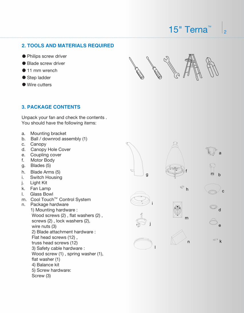
3. PACKAGE CONTENTS
Unpack your fan and check the contents . You should have the following items:
a. Mounting bracket b. Ball / downrod assembly (1)c. Canopyd. Canopy Hole Covere. Coupling cover f. Motor Bodyg. Blades (5)h. Blade Arms (5)
j. Light Kit k. Fan Lamp l. Glass Bowl
n. Package hardware 1) Mounting hardware : Wood screws (2) , flat washers (2) , screws (2) , lock washers (2), wire nuts (3) 2) Blade attachment hardware : Flat head screws (12) , truss head screws (12) 3) Safety cable hardware : Wood screw (1) , spring washer (1), flat washer (1) 4) Balance kit 5) Screw hardware: Screw (3)
m. Cool Touch Control System
Philips screw driver
Blade screw driver
11 mm wrench
Step ladder
Wire cutters
2. TOOLS AND MATERIALS REQUIRED
15" TernaTM
i. Switch Housing
TM
j
a
b
c
d
e
fg
h
i
kl
m
n
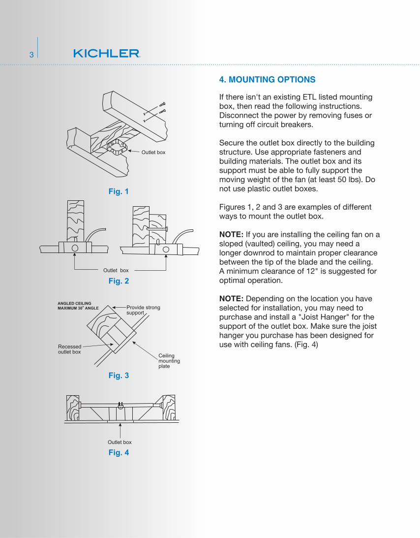
4. MOUNTING OPTIONS
Outlet box
Provide strongsupport
Recessedoutlet box
Ceilingmountingplate
Outlet box
Fig. 1
Fig. 3
Fig. 4
Outlet box
Fig. 2
ANGLED CEILINGMAXIMUM 30° ANGLE
3
If there isn't an existing ETL listed mounting box, then read the following instructions. Disconnect the power by removing fuses or turning off circuit breakers.
Secure the outlet box directly to the building structure. Use appropriate fasteners and building materials. The outlet box and its support must be able to fully support the moving weight of the fan (at least 50 lbs). Do not use plastic outlet boxes.
Figures 1, 2 and 3 are examples of different ways to mount the outlet box.
NOTE: If you are installing the ceiling fan on a sloped (vaulted) ceiling, you may need a longer downrod to maintain proper clearance between the tip of the blade and the ceiling. A minimum clearance of 12" is suggested for optimal operation.
NOTE: Depending on the location you have selected for installation, you may need to purchase and install a "Joist Hanger" for the support of the outlet box. Make sure the joist hanger you purchase has been designed for use with ceiling fans. (Fig. 4)
4
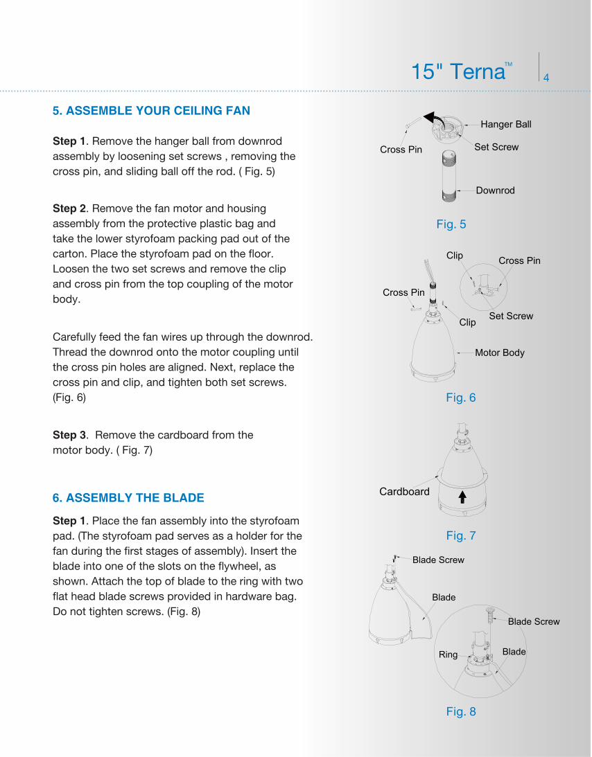
5. ASSEMBLE YOUR CEILING FAN
6. ASSEMBLY THE BLADE
Step 3. Remove the cardboard from the motor body. ( Fig. 7)
Step 1. Remove the hanger ball from downrod assembly by loosening set screws , removing the cross pin, and sliding ball off the rod. ( Fig. 5)
Step 1. Place the fan assembly into the styrofoam pad. (The styrofoam pad serves as a holder for the fan during the first stages of assembly). Insert the blade into one of the slots on the flywheel, as shown. Attach the top of blade to the ring with two flat head blade screws provided in hardware bag. Do not tighten screws. (Fig. 8)
Step 2. Remove the fan motor and housing assembly from the protective plastic bag and take the lower styrofoam packing pad out of the carton. Place the styrofoam pad on the floor. Loosen the two set screws and remove the clip and cross pin from the top coupling of the motor body.
Carefully feed the fan wires up through the downrod. Thread the downrod onto the motor coupling until the cross pin holes are aligned. Next, replace the cross pin and clip, and tighten both set screws. (Fig. 6)
15" TernaTM
Fig. 7
Fig. 8
Fig. 5
Downrod
Cross Pin Set Screw
Hanger Ball
Fig. 6
Cross Pin
Set Screw
Clip
Clip
Cross Pin
Motor Body
Cardboard
Blade
Blade Screw
Blade
Blade Screw
Ring
5
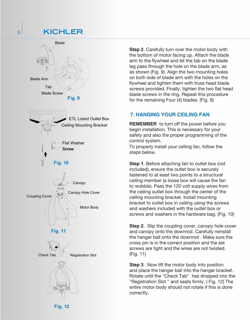
Step 2. Carefully turn over the motor body with the bottom of motor facing up. Attach the blade arm to the flywheel and let the tab on the blade leg pass through the hole on the blade arm, as as shown (Fig. 9). Align the two mounting holes on both side of blade arm with the holes on the flywheel and tighten them with truss head blade screws provided. Finally, tighten the two flat head blade screws in the ring. Repeat this procedure for the remaining Four (4) blades. (Fig. 9)
Step 2. Slip the coupling cover, canopy hole cover and canopy onto the downrod. Carefully reinstall the hanger ball onto the downrod . Make sure the cross pin is in the correct position and the set screws are tight and the wires are not twisted. (Fig. 11)
Step 3. Now lift the motor body into position and place the hanger ball into the hanger bracket. Rotate until the "Check Tab" has dropped into the "Registration Slot " and seats firmly. ( Fig. 12) The entire motor body should not rotate if this is done correctly.
Fig. 11
Canopy
Canopy Hole CoverCoupling Cover
Motor Body
REMEMBER to turn off the power before you begin installation. This is necessary for your safety and also the proper programming of the control system.To properly install your ceiling fan, follow the steps below.
Step 1. Before attaching fan to outlet box (not included), ensure the outlet box is securely fastened to at least two points to a structural ceiling member (a loose box will cause the fan to wobble). Pass the 120 volt supply wires from the ceiling outlet box through the center of the ceiling mounting bracket. Install mounting bracket to outlet box in ceiling using the screws and washers included with the outlet box or screws and washers in the hardware bag. (Fig. 10)
Fig. 10
Flat Washer Screw
Ceiling Mounting BracketETL Listed Outlet Box
Screw
Fig. 9
7. HANGING YOUR CEILING FAN
Fig. 12
Check Tab Registration Slot
Blade
Blade Arm
Blade ScrewTab
6
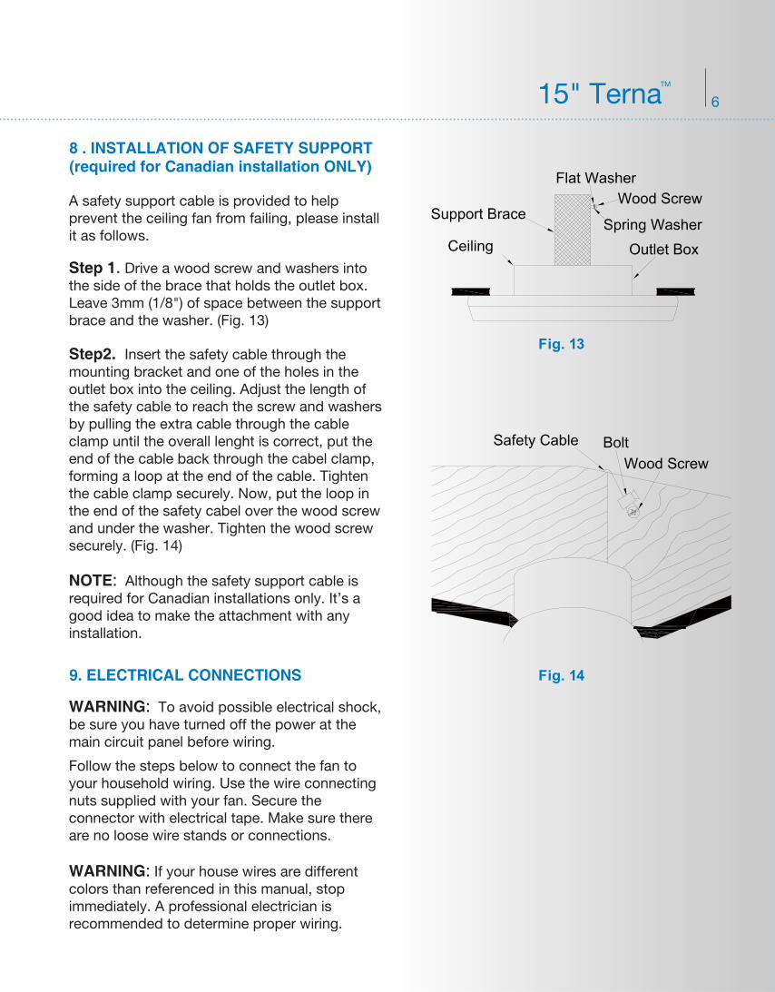
8 . INSTALLATION OF SAFETY SUPPORT(required for Canadian installation ONLY)
9. ELECTRICAL CONNECTIONS
A safety support cable is provided to help prevent the ceiling fan from failing, please install it as follows.
Step2. Insert the safety cable through the mounting bracket and one of the holes in the outlet box into the ceiling. Adjust the length of the safety cable to reach the screw and washers by pulling the extra cable through the cable clamp until the overall lenght is correct, put the end of the cable back through the cabel clamp, forming a loop at the end of the cable. Tighten the cable clamp securely. Now, put the loop in the end of the safety cabel over the wood screw and under the washer. Tighten the wood screw securely. (Fig. 14)
NOTE: Although the safety support cable is required for Canadian installations only. It’s a good idea to make the attachment with any installation.
WARNING: To avoid possible electrical shock, be sure you have turned off the power at the main circuit panel before wiring.
WARNING: If your house wires are different colors than referenced in this manual, stop immediately. A professional electrician is recommended to determine proper wiring.
Follow the steps below to connect the fan to your household wiring. Use the wire connecting nuts supplied with your fan. Secure the connector with electrical tape. Make sure there are no loose wire stands or connections.
Step 1. Drive a wood screw and washers into the side of the brace that holds the outlet box. Leave 3mm (1/8") of space between the support brace and the washer. (Fig. 13)
15" TernaTM
Fig. 14
Fig. 13
Safety Cable BoltWood Screw
Flat WasherWood Screw
Spring WasherOutlet Box
Support Brace
Ceiling
7
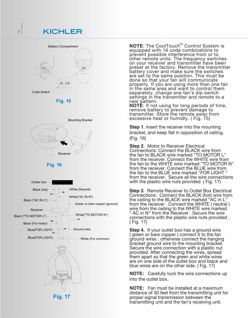
Step 3. Remote Receiver to Outlet Box Electrical Connections: Connect the BLACK (hot) wire from the ceiling to the BLACK wire marked “AC in L” from the receiver . Connect the WHITE ( neutral ) wire from the ceiling to the WHITE wire marked “ AC in N” from the Receiver . Secure the wire connections with the plastic wire nuts provided . ( Fig. 17)
Step 1. Insert the receiver into the mounting bracket, and keep flat in opposition of ceiling. (Fig. 16)
Step 2. Motor to Receiver Electrical Connections: Connect the BLACK wire from the fan to BLACK wire marked "TO MOTOR L" from the receiver. Connect the WHITE wire from the fan to the WHITE wire marked "TO MOTOR N" from the receiver. Connect the BLUE wire from the fan to the BLUE wire marked "FOR LIGHT " from the receiver. Secure all the wire connections with the plastic wire nuts provided. ( Fig. 17)
NOTE: The CoolTouch Control System is equipped with 16 code combinations to prevent possible interference from or to other remote units. The frequency switches on your receiver and transmitter have been preset at the factory. Remove the transmitter battery cover and make sure the switches are set to the same position. This must be done so that your fan will communicate properly. If you are using more than one fan in the same area and want to control them separately, change one fan’s dip switch settings in the transmitter and remote to a new pattern. NOTE: If not using for long periods of time, remove battery to prevent damage to transmitter. Store the remote away from excessive heat or humidly. ( Fig. 15)
Step 4. If your outlet box has a ground wire ( green or bare copper ) connect it to the fan ground wires : otherwise connect the hanging bracket ground wire to the mounting bracket. Secure the wire connection with a plastic nut provided. After connecting the wires, spread them apart so that the green and white wires are on one side of the outlet box and black and blue wires are on the other side. ( Fig. 17)
NOTE: Carefully tuck the wire connections up into the outlet box.
NOTE: Fan must be installed at a maximum distance of 30 feet from the transmitting unit for proper signal transmission between the transmitting unit and the fan’s receiving unit.
TM
Fig. 15
ON ECE
ON ECE
Battery Compartment
Code Switch
Fig. 16
Mounting Bracket
Receiver
Fig. 17
White (For common)
Blue(FOR LIGHT) Ground wire
White("AC IN N")
White("TO MOTOR N")
Green or bare copper (ground)
Black (For motor)
Black ("TO MOTOR L")
Black ("AC IN L")
Receiver
Black (hot)
Outlex box
White (Neutral)
Blue(FOR LIGHT)
8 15" TernaTM
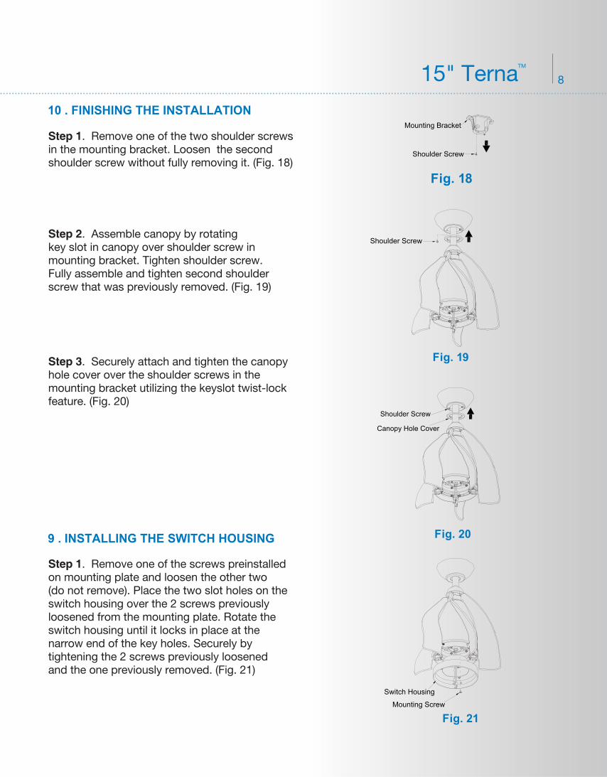
10 . FINISHING THE INSTALLATION
9 . INSTALLING THE SWITCH HOUSING
Step 1. Remove one of the two shoulder screws in the mounting bracket. Loosen the second shoulder screw without fully removing it. (Fig. 18)
Step 2. Assemble canopy by rotating key slot in canopy over shoulder screw in mounting bracket. Tighten shoulder screw. Fully assemble and tighten second shoulder screw that was previously removed. (Fig. 19)
Step 3. Securely attach and tighten the canopy hole cover over the shoulder screws in the mounting bracket utilizing the keyslot twist-lock feature. (Fig. 20)
Step 1. Remove one of the screws preinstalled on mounting plate and loosen the other two (do not remove). Place the two slot holes on the switch housing over the 2 screws previously loosened from the mounting plate. Rotate the switch housing until it locks in place at the narrow end of the key holes. Securely by tightening the 2 screws previously loosened and the one previously removed. (Fig. 21)
Fig. 18
Shoulder Screw
Mounting Bracket
Fig. 19
Shoulder Screw
Fig. 20
Shoulder Screw
Canopy Hole Cover
Fig. 21Mounting Screw
Switch Housing
9
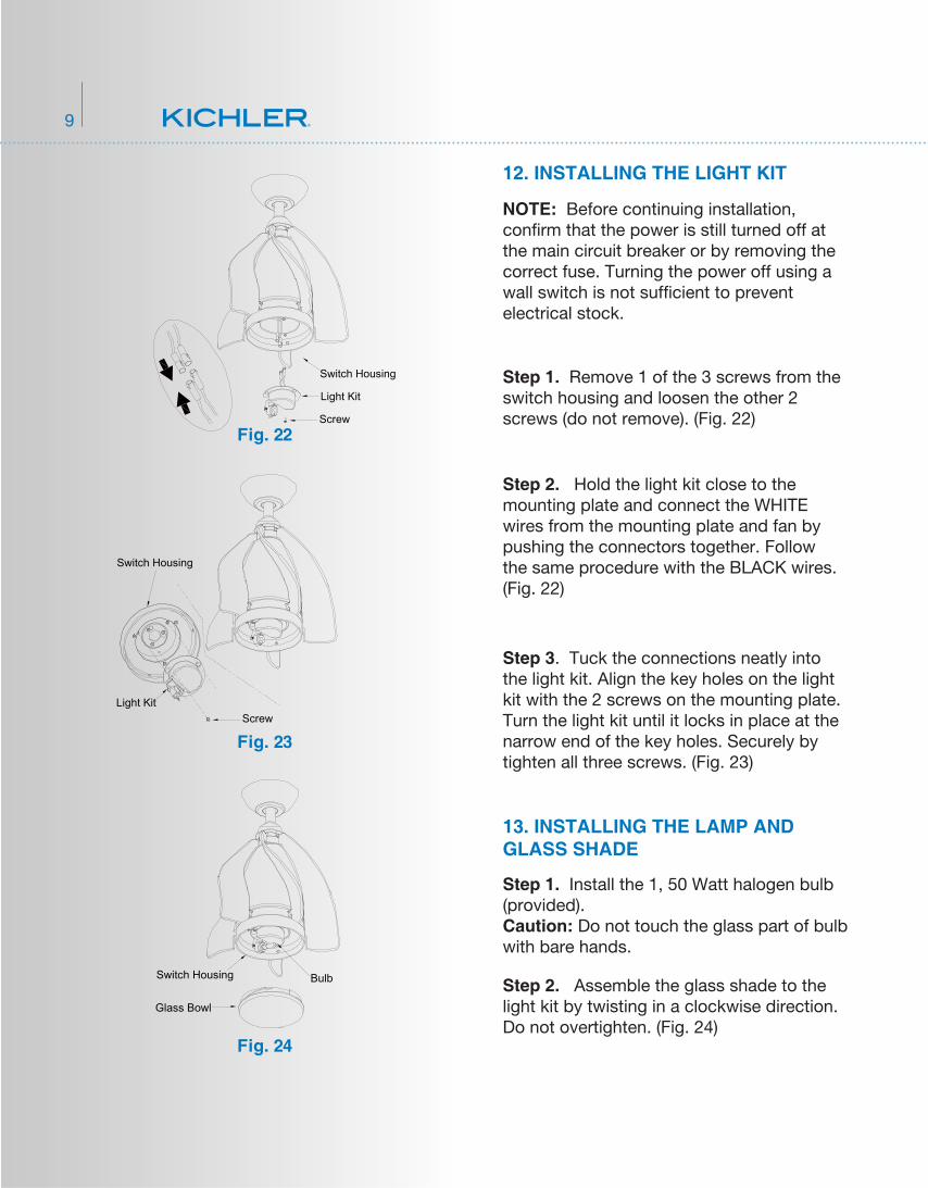
Step 1. Remove 1 of the 3 screws from the switch housing and loosen the other 2 screws (do not remove). (Fig. 22)
Step 1. Install the 1, 50 Watt halogen bulb (provided). Caution: Do not touch the glass part of bulb with bare hands.
Step 2. Hold the light kit close to the mounting plate and connect the WHITE wires from the mounting plate and fan by pushing the connectors together. Follow the same procedure with the BLACK wires. (Fig. 22)
Step 2. Assemble the glass shade to the light kit by twisting in a clockwise direction. Do not overtighten. (Fig. 24)
NOTE: Before continuing installation, con�rm that the power is still turned off at the main circuit breaker or by removing the correct fuse. Turning the power off using a wall switch is not suf�cient to prevent electrical stock.
12. INSTALLING THE LIGHT KIT
13. INSTALLING THE LAMP AND GLASS SHADE
Fig. 23
Fig. 24
Fig. 22
Step 3. Tuck the connections neatly into the light kit. Align the key holes on the light kit with the 2 screws on the mounting plate. Turn the light kit until it locks in place at the narrow end of the key holes. Securely by tighten all three screws. (Fig. 23)
Switch Housing
Light Kit
Screw
Switch Housing
Light KitScrew
Switch Housing
Glass Bowl
Bulb
10 15" TernaTM
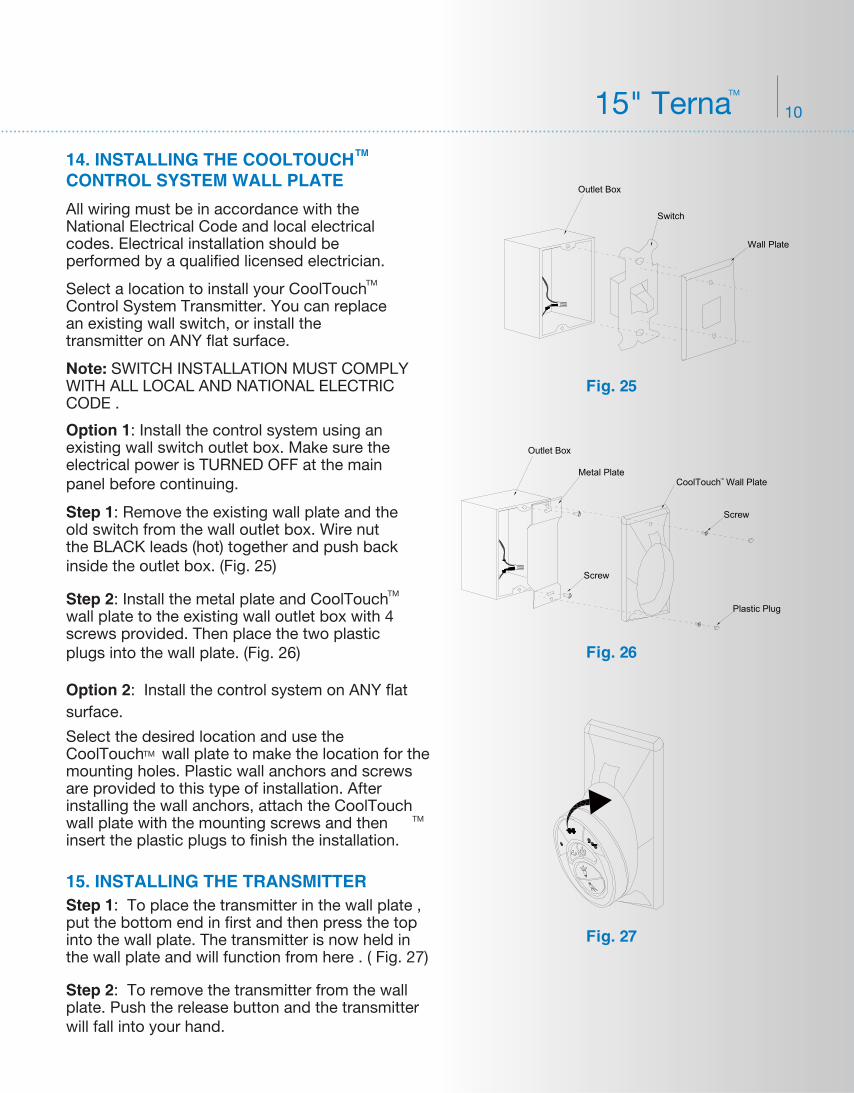
Option 1: Install the control system using an existing wall switch outlet box. Make sure the electrical power is TURNED OFF at the main panel before continuing.
Option 2: Install the control system on ANY flat surface.
Step 1: Remove the existing wall plate and the old switch from the wall outlet box. Wire nut the BLACK leads (hot) together and push back inside the outlet box. (Fig. 25)
Fig. 27
Fig. 25
Fig. 26
15. INSTALLING THE TRANSMITTER
14. INSTALLING THE COOLTOUCH CONTROL SYSTEM WALL PLATE
TM
All wiring must be in accordance with the National Electrical Code and local electrical codes. Electrical installation should be performed by a qualified licensed electrician.
Select a location to install your CoolTouch Control System Transmitter. You can replace an existing wall switch, or install the transmitter on ANY flat surface.
Note: SWITCH INSTALLATION MUST COMPLY WITH ALL LOCAL AND NATIONAL ELECTRIC CODE .
TM
Select the desired location and use the CoolTouch wall plate to make the location for the mounting holes. Plastic wall anchors and screws are provided to this type of installation. After installing the wall anchors, attach the CoolTouch wall plate with the mounting screws and then insert the plastic plugs to finish the installation.
TM
TM
Step 1: To place the transmitter in the wall plate , put the bottom end in first and then press the top into the wall plate. The transmitter is now held in the wall plate and will function from here . ( Fig. 27)
Step 2: Install the metal plate and CoolTouch wall plate to the existing wall outlet box with 4 screws provided. Then place the two plastic plugs into the wall plate. (Fig. 26)
TM
Step 2: To remove the transmitter from the wall plate. Push the release button and the transmitter will fall into your hand.
CoolTouch Wall Plate
Screw
TM
Plastic Plug
Outlet Box
Metal Plate
Screw
Outlet Box
Switch
Wall Plate
11
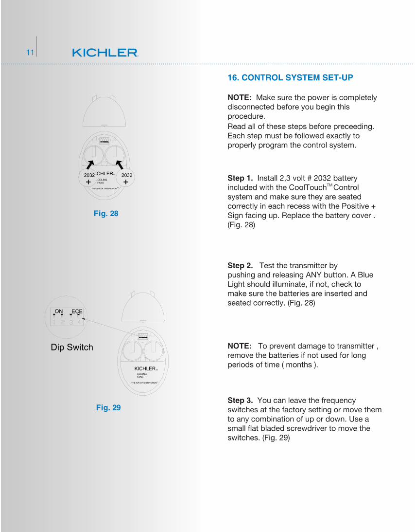
16. CONTROL SYSTEM SET-UP
Fig. 29
Fig. 28
NOTE: Make sure the power is completely disconnected before you begin this procedure.
NOTE: To prevent damage to transmitter , remove the batteries if not used for long periods of time ( months ).
Read all of these steps before preceeding. Each step must be followed exactly to properly program the control system.
Step 1. Install 2,3 volt # 2032 battery included with the CoolTouch Control system and make sure they are seated correctly in each recess with the Positive + Sign facing up. Replace the battery cover . (Fig. 28)
TM
Step 2. Test the transmitter by pushing and releasing ANY button. A Blue Light should illuminate, if not, check to make sure the batteries are inserted and seated correctly. (Fig. 28)
Step 3. You can leave the frequency switches at the factory setting or move them to any combination of up or down. Use a small �at bladed screwdriver to move the switches. (Fig. 29)
ONECE
2032
+2032
+CHLERCEILING FANS
THE AIR OF DISTINCTION
R
TM
ON ECE
ONECE
Dip Switch
KICHLERCEILING FANS
THE AIR OF DISTINCTION
R
TM
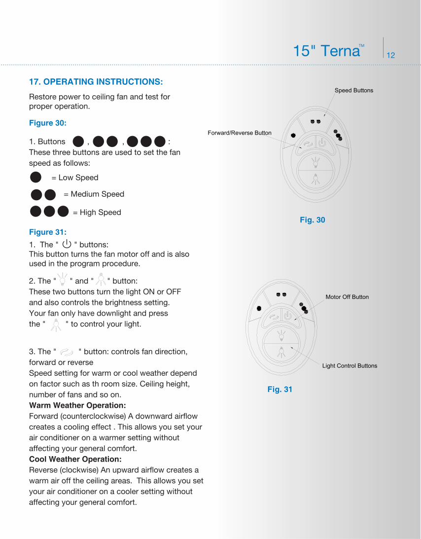
Figure 30:
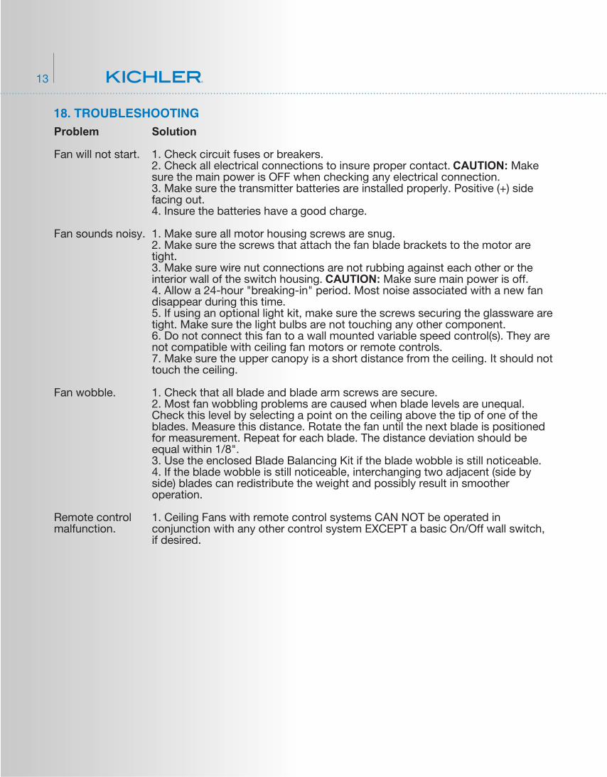
Figure 31:
1. Buttons , , :These three buttons are used to set the fan speed as follows:
17. OPERATING INSTRUCTIONS:
= Low Speed
= Medium Speed
= High Speed
1. The " " buttons:This button turns the fan motor off and is also used in the program procedure.
2. The " " and " " button:These two buttons turn the light ON or OFF and also controls the brightness setting. Your fan only have downlight and press the " " to control your light.
3. The " " button: controls fan direction, forward or reverseSpeed setting for warm or cool weather depend on factor such as th room size. Ceiling height, number of fans and so on.Warm Weather Operation: Forward (counterclockwise) A downward airflow creates a cooling effect . This allows you set your air conditioner on a warmer setting without affecting your general comfort.Cool Weather Operation: Reverse (clockwise) An upward airflow creates a warm air off the ceiling areas. This allows you set your air conditioner on a cooler setting without affecting your general comfort.
Restore power to ceiling fan and test for proper operation.
Fig. 31
Motor Off Button
Light Control Buttons
Fig. 30
Speed Buttons
Forward/Reverse Button
12 15" TernaTM
Problem
Fan will not start.
Fan sounds noisy.
Fan wobble.
Remote control malfunction.
Solution
1. Check circuit fuses or breakers.2. Check all electrical connections to insure proper contact. CAUTION: Make sure the main power is OFF when checking any electrical connection.3. Make sure the transmitter batteries are installed properly. Positive (+) side facing out.4. Insure the batteries have a good charge.
1. Make sure all motor housing screws are snug.2. Make sure the screws that attach the fan blade brackets to the motor are tight.3. Make sure wire nut connections are not rubbing against each other or the interior wall of the switch housing. CAUTION: Make sure main power is off.4. Allow a 24-hour "breaking-in" period. Most noise associated with a new fan disappear during this time.5. If using an optional light kit, make sure the screws securing the glassware are tight. Make sure the light bulbs are not touching any other component.6. Do not connect this fan to a wall mounted variable speed control(s). They are not compatible with ceiling fan motors or remote controls.7. Make sure the upper canopy is a short distance from the ceiling. It should not touch the ceiling.
1. Check that all blade and blade arm screws are secure.2. Most fan wobbling problems are caused when blade levels are unequal. Check this level by selecting a point on the ceiling above the tip of one of the blades. Measure this distance. Rotate the fan until the next blade is positioned for measurement. Repeat for each blade. The distance deviation should be equal within 1/8".3. Use the enclosed Blade Balancing Kit if the blade wobble is still noticeable.4. If the blade wobble is still noticeable, interchanging two adjacent (side by side) blades can redistribute the weight and possibly result in smoother operation.
1. Ceiling Fans with remote control systems CAN NOT be operated in conjunction with any other control system EXCEPT a basic On/Off wall switch, if desired.
18. TROUBLESHOOTING
13