1.5-Fast Reactor Fuels · 2019-06-05 · FAST REACTOR FUELS drhgfdjhngngfmhgmghmghjmghfmf TANJU...
35
FAST REACTOR FUELS TANJU SOFU ARGONNE NATIONAL LABORATORY March 26, 2019 Fast Reactor Technology Training U.S. Nuclear Regulatory Commission H Fuel Pin and Wire Corner Subchannel Edge Subchannel Interior Subchannel Duct Wall Fuel Pin D P Wire Wrap
Transcript of 1.5-Fast Reactor Fuels · 2019-06-05 · FAST REACTOR FUELS drhgfdjhngngfmhgmghmghjmghfmf TANJU...
FAST REACTOR FUELS
drhgfdjhngngfmhgmghmghjmghfmf
TANJU SOFUARGONNE NATIONAL LABORATORY
March 26, 2019Fast Reactor Technology TrainingU.S. Nuclear Regulatory Commission
H
Fuel Pinand Wire
CornerSubchannel
EdgeSubchannel
InteriorSubchannel
Duct Wall
Fuel Pin D
P
Wire Wrap
OUTLINE
Fast reactor fuel types U.S. experience Fuel pin and assembly design Fuel design considerations and challenges
– Oxide fuel– Metallic fuel
Oxide and metallic fuel comparisons Fuel failure modes and consequences Metallic fuel irradiation and transient testing experience
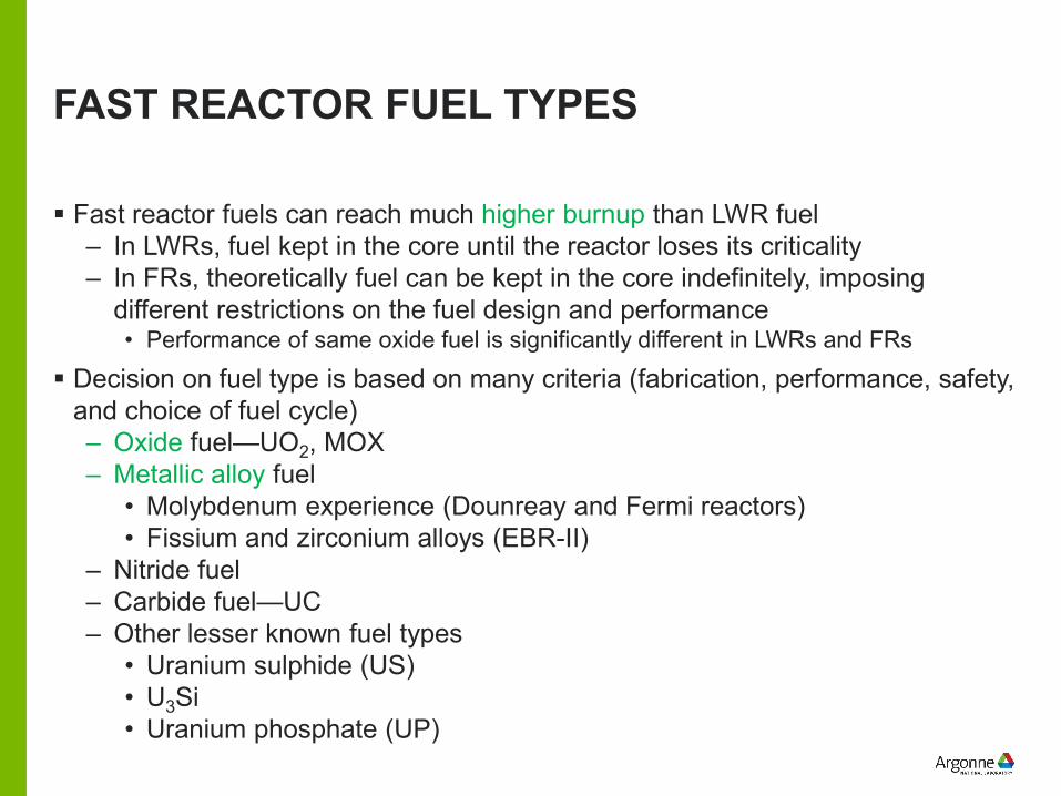
FAST REACTOR FUEL TYPES
Fast reactor fuels can reach much higher burnup than LWR fuel– In LWRs, fuel kept in the core until the reactor loses its criticality– In FRs, theoretically fuel can be kept in the core indefinitely, imposing
different restrictions on the fuel design and performance• Performance of same oxide fuel is significantly different in LWRs and FRs
Decision on fuel type is based on many criteria (fabrication, performance, safety, and choice of fuel cycle)– Oxide fuel—UO2, MOX– Metallic alloy fuel
• Molybdenum experience (Dounreay and Fermi reactors)• Fissium and zirconium alloys (EBR-II)
– Nitride fuel– Carbide fuel—UC– Other lesser known fuel types
• Uranium sulphide (US)• U3Si• Uranium phosphate (UP)
MOST COMMON FAST REACTOR FUELS
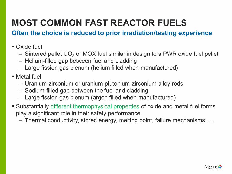
Oxide fuel– Sintered pellet UO2 or MOX fuel similar in design to a PWR oxide fuel pellet– Helium-filled gap between fuel and cladding– Large fission gas plenum (helium filled when manufactured)
Metal fuel– Uranium-zirconium or uranium-plutonium-zirconium alloy rods– Sodium-filled gap between the fuel and cladding– Large fission gas plenum (argon filled when manufactured)
Substantially different thermophysical properties of oxide and metal fuel forms play a significant role in their safety performance– Thermal conductivity, stored energy, melting point, failure mechanisms, …
Often the choice is reduced to prior irradiation/testing experience
U.S. SFR FUELS EXPERIENCE (1/2)
SFRs have been extensively studied and operated by DOE and its predecessor, AEC– Experience with EBR-I, EBR-II, FFTF, and CRBR project
Early U.S. SFR experience focused on metal-alloy fuel– EBR-II tests in late 1960’s showed limited success achieving only low burnup
Oxide fuel form was selected for further development in FFTF and CRBR project– Based on experience in commercial LWRs and naval reactors
After CRBR project was canceled, DOE continued on with Advanced Liquid Metal Reactor (ALMR) and Integral Fast Reactor (IFR) programs– Emphasis back on a pool-type SFRs with metal alloy fuel to address
regulatory concerns related to severe accidents Subsequent metallic fuel testing in 1980s (during IFR program) demonstrated
that burnup limitation could be overcome by changing the fuel design– Larger fuel-cladding gap to accommodate irradiation induced swelling and
achieve lower smeared density
U.S. SFR FUELS EXPERIENCE (2/2)
Under the ALMR program, PRISM (GE) and SAFR (Rockwell/WEC) concepts submitted their Preliminary Safety Information Document to NRC in 1986– NRC’s Pre-application Safety Evaluation Reports (NUREG-1368 and 1369)
identified “incomplete information on the proposed metallic fuel” as one of the key regulatory issues
IFR program (until its termination in 1994) as well as ongoing work under DOE's Advanced Reactor Technologies (ART) program and Advanced Fuels Campaign continued addressing this issue– PRISM, TWR, ARC-100 (and 4S, though not a U.S. design) all propose to
use metallic fuel based on this experience
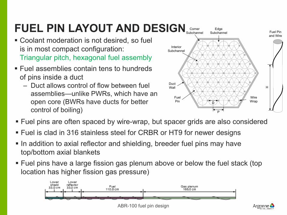
FUEL PIN LAYOUT AND DESIGN Coolant moderation is not desired, so fuel
is in most compact configuration: Triangular pitch, hexagonal fuel assembly Fuel assemblies contain tens to hundreds
of pins inside a duct– Duct allows control of flow between fuel
assemblies—unlike PWRs, which have an open core (BWRs have ducts for better control of boiling)
H
Fuel Pinand Wire
CornerSubchannel
EdgeSubchannel
InteriorSubchannel
Duct Wall
Fuel Pin D
P
Wire Wrap
Fuel pins are often spaced by wire-wrap, but spacer grids are also considered Fuel is clad in 316 stainless steel for CRBR or HT9 for newer designs In addition to axial reflector and shielding, breeder fuel pins may have
top/bottom axial blankets Fuel pins have a large fission gas plenum above or below the fuel stack (top
location has higher fission gas pressure)
ABR-100 fuel pin design
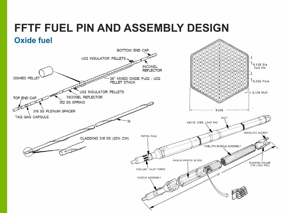
FFTF FUEL PIN AND ASSEMBLY DESIGNOxide fuel
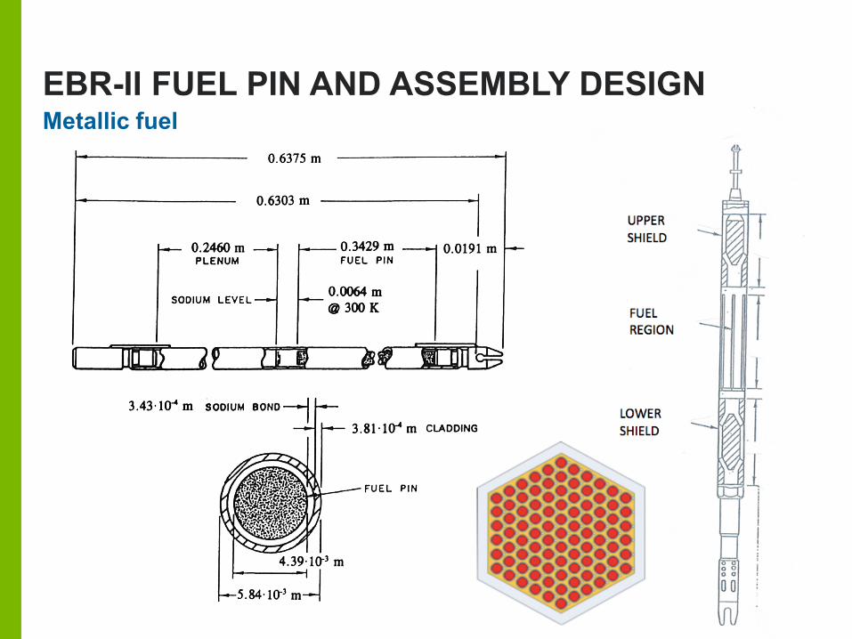
EBR-II FUEL PIN AND ASSEMBLY DESIGNMetallic fuel
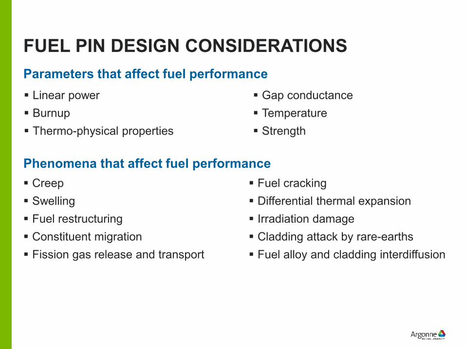
FUEL PIN DESIGN CONSIDERATIONS
Linear power Burnup Thermo-physical properties
Parameters that affect fuel performance
Creep Swelling Fuel restructuring Constituent migration Fission gas release and transport
Phenomena that affect fuel performance
Gap conductance Temperature Strength
Fuel cracking Differential thermal expansion Irradiation damage Cladding attack by rare-earths Fuel alloy and cladding interdiffusion
FAST REACTOR FUEL DESIGN CHALLENGES
Higher burnup– Typical LWR fuel burnup is ~ 2–3%– SFR fuels typically reach burnup well in excess of 10% and that results in
significant swelling and fission gas pressure inside the pin Greater fuel swelling
– Both metallic and oxide fuel pin designs can accommodate it Fuel-Cladding Mechanical Interaction (FCMI)
– Bigger challenge for hard, strong ceramic fuel forms and it can impose limits on maximum burnup
Fuel-Cladding Chemical Interaction (FCCI)– Puts operational limit to coolant outlet temperature for a metallic fuel core
Fuel-coolant compatibility– Oxide fuel chemically reacts with the sodium coolant imposing stricter limits
on fuel pin failures to prevent potential flow blockages
OXIDE FUEL (1/3)
High operating and manufacturing experience in part from LWRs Normally manufactured through powder metallurgy
– Mixture is cold-compacted into a pellet– Pellets are sintered at ~1600°C to achieve desired densification level
Fabrication
Oxygen ions are arrayed in a simple cubic structure, and the heavy metal ions form a face-centered cubic sublattice Relatively brittle material at temperatures less than half the melting point
Physical properties
Some porosity is intentionally incorporated to accommodate excessive fuel swelling in fast spectrum with high burnup– 85–90% of theoretical density (even lower smeared density)
0.15 to 0.45% per atom-% burnup of total swelling is due to solid fission products Substantially greater swelling results from fission gases
Swelling
OXIDE FUEL (2/3)
Steep radial temperature profiles cause columnar and equiaxed grains to develop after a few hours of irradiation Radial profile of oxygen to metal ratio also rapidly changes with impact on
thermo-physical properties
Microstructure changes
Once released from the fuel matrix, fission gas is vented to collecting zones– Usually a fission gas plenum above or below the fuel stack
Fuel temperature– For T<1000oC, fission gas mobility is low and there is little gas escape– For 1000oC<T<1600oC, atomic motion allows some diffusion, and some
amount of gas can escape from fuel matrix– For T>1600oC, thermal gradients can drive gas bubbles and closed pores
over distances comparable to grain sizes
Fission gas release
OXIDE FUEL (3/3)
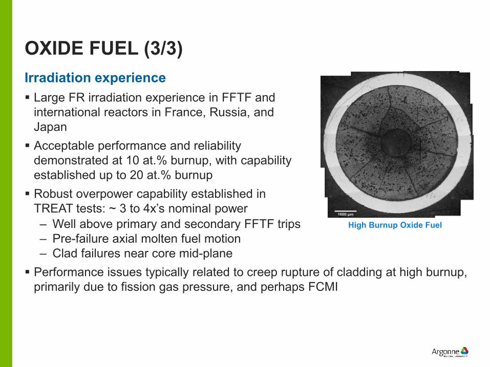
Large FR irradiation experience in FFTF and international reactors in France, Russia, and Japan Acceptable performance and reliability
demonstrated at 10 at.% burnup, with capability established up to 20 at.% burnup Robust overpower capability established in
TREAT tests: ~ 3 to 4x’s nominal power
Irradiation experience
High Burnup Oxide Fuel– Well above primary and secondary FFTF trips– Pre-failure axial molten fuel motion– Clad failures near core mid-plane
Performance issues typically related to creep rupture of cladding at high burnup, primarily due to fission gas pressure, and perhaps FCMI
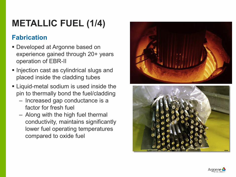
METALLIC FUEL (1/4)
Developed at Argonne based on experience gained through 20+ years operation of EBR-II Injection cast as cylindrical slugs and
placed inside the cladding tubes Liquid-metal sodium is used inside the
pin to thermally bond the fuel/cladding– Increased gap conductance is a
factor for fresh fuel– Along with the high fuel thermal
conductivity, maintains significantly lower fuel operating temperatures compared to oxide fuel
Fabrication
METALLIC FUEL (2/4)
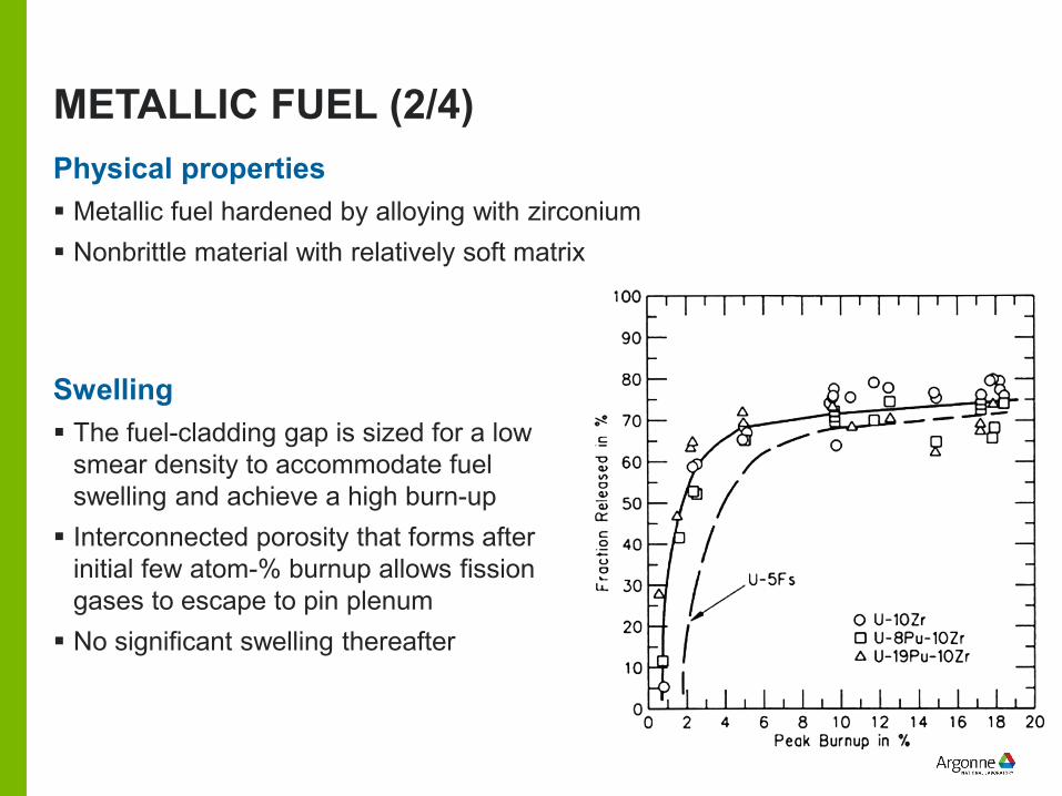
Metallic fuel hardened by alloying with zirconium Nonbrittle material with relatively soft matrix
Physical properties
The fuel-cladding gap is sized for a low smear density to accommodate fuel swelling and achieve a high burn-up Interconnected porosity that forms after
initial few atom-% burnup allows fission gases to escape to pin plenum No significant swelling thereafter
Swelling
METALLIC FUEL (3/4)
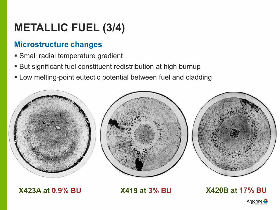
Small radial temperature gradient But significant fuel constituent redistribution at high burnup Low melting-point eutectic potential between fuel and cladding
Microstructure changes
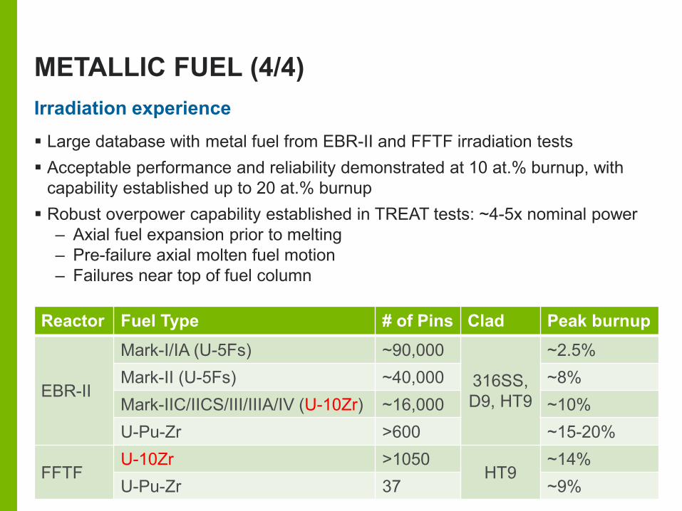
METALLIC FUEL (4/4)Irradiation experience Large database with metal fuel from EBR-II and FFTF irradiation tests Acceptable performance and reliability demonstrated at 10 at.% burnup, with
capability established up to 20 at.% burnup Robust overpower capability established in TREAT tests: ~4-5x nominal power
– Axial fuel expansion prior to melting– Pre-failure axial molten fuel motion– Failures near top of fuel column
Reactor Fuel Type # of Pins Clad Peak burnup
EBR-II
Mark-I/IA (U-5Fs) ~90,000
316SS, D9, HT9
~2.5%Mark-II (U-5Fs) ~40,000 ~8%Mark-IIC/IICS/III/IIIA/IV (U-10Zr) ~16,000 ~10%U-Pu-Zr >600 ~15-20%
FFTFU-10Zr >1050
HT9~14%
U-Pu-Zr 37 ~9%
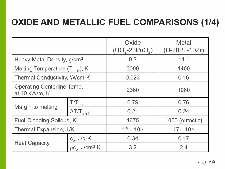
OXIDE AND METALLIC FUEL COMPARISONS (1/4)
Oxide(UO2-20PuO2)
Metal(U-20Pu-10Zr)
Heavy Metal Density, g/cm3 9.3 14.1Melting Temperature (Tmelt), K 3000 1400Thermal Conductivity, W/cm-K 0.023 0.16Operating Centerline Temp.at 40 kW/m, K 2360 1060
Margin to meltingT/Tmelt 0.79 0.76ΔT/Tmelt 0.21 0.24
Fuel-Cladding Solidus, K 1675 1000 (eutectic)Thermal Expansion, 1/K 12× 10-6 17× 10-6
Heat Capacitycp, J/g-K 0.34 0.17⍴cp, J/cm3-K 3.2 2.4
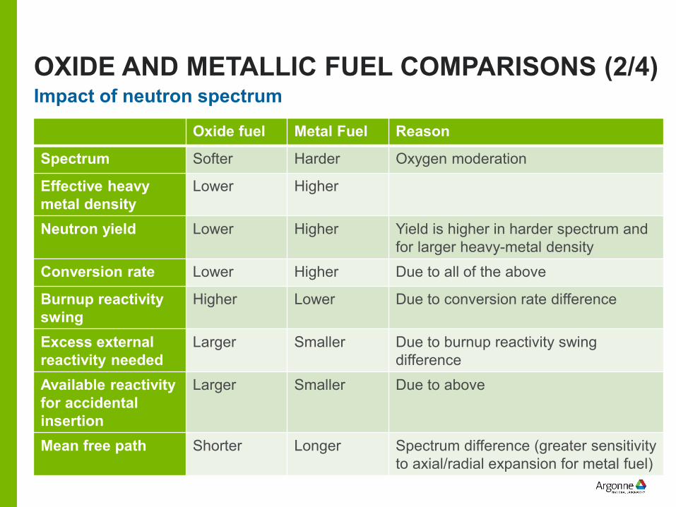
OXIDE AND METALLIC FUEL COMPARISONS (2/4)Impact of neutron spectrum
Oxide fuel Metal Fuel Reason
Spectrum Softer Harder Oxygen moderation
Effective heavy metal density
Lower Higher
Neutron yield Lower Higher Yield is higher in harder spectrum and for larger heavy-metal density
Conversion rate Lower Higher Due to all of the above
Burnup reactivity swing
Higher Lower Due to conversion rate difference
Excess external reactivity needed
Larger Smaller Due to burnup reactivity swing difference
Available reactivity for accidental insertion
Larger Smaller Due to above
Mean free path Shorter Longer Spectrum difference (greater sensitivity to axial/radial expansion for metal fuel)
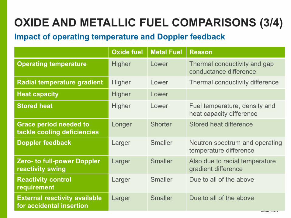
OXIDE AND METALLIC FUEL COMPARISONS (3/4)Impact of operating temperature and Doppler feedback
Oxide fuel Metal Fuel Reason
Operating temperature Higher Lower Thermal conductivity and gap conductance difference
Radial temperature gradient Higher Lower Thermal conductivity difference
Heat capacity Higher Lower
Stored heat Higher Lower Fuel temperature, density and heat capacity difference
Grace period needed to tackle cooling deficiencies
Longer Shorter Stored heat difference
Doppler feedback Larger Smaller Neutron spectrum and operating temperature difference
Zero- to full-power Doppler reactivity swing
Larger Smaller Also due to radial temperature gradient difference
Reactivity control requirement
Larger Smaller Due to all of the above
External reactivity available for accidental insertion
Larger Smaller Due to all of the above
OXIDE AND METALLIC FUEL COMPARISONS (4/4) Overall, oxide fuel offers a very robust and chemically stable fuel form with
significant manufacturing and irradiation experience from past LWR and international SFR operations– Metallic fuel has a softer matrix, can experience significant constituent
migration at high burnup, and can chemically interact with iron in cladding High thermal conductivity and gap conductance is an advantage for metallic fuel
– Low steady-state and transient temperatures, and flat temperature profile Since metal fuel cladding generally fails below the coolant boiling point,
damaged metal fuel pins remain coolable Despite big difference in melting point, both oxide and metal fuels have similar
margin to melting during accidents Phenomena depending on diffusional rate processes, such as creep and fission
gas release, are also similar Fuel-coolant compatibility
– Oxide fuel chemically reacts with sodium coolant– Metal fuel is compatible with sodium coolant and minor clad failures ca be
tolerated
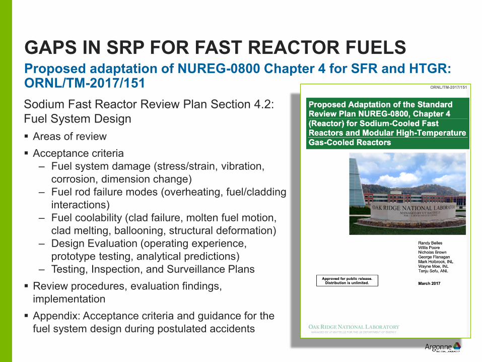
GAPS IN SRP FOR FAST REACTOR FUELS
Sodium Fast Reactor Review Plan Section 4.2: Fuel System Design Areas of review Acceptance criteria
– Fuel system damage (stress/strain, vibration, corrosion, dimension change)
– Fuel rod failure modes (overheating, fuel/cladding interactions)
– Fuel coolability (clad failure, molten fuel motion, clad melting, ballooning, structural deformation)
– Design Evaluation (operating experience, prototype testing, analytical predictions)
– Testing, Inspection, and Surveillance Plans Review procedures, evaluation findings,
implementation Appendix: Acceptance criteria and guidance for the
fuel system design during postulated accidents
Proposed adaptation of NUREG-0800 Chapter 4 for SFR and HTGR: ORNL/TM-2017/151
FUEL FAILURE MODES
FCMI: Can be a contributor to fuel failure for both high-smeared density oxide and metal fuel forms– Not a significant factor for low smeared fuels (larger fuel cladding radial gap
leaves room for early fuel swelling and allows development of inter-connected porosity in fuel matrix for release of fission gas to pin plenum)
FCCI: Major contributor to metallic fuel pin failure due to formation of low melting-point intermetallic eutectic between the uranium and iron at the fuel-cladding interface– When zirconium is used in the metal fuel alloy (also with some coated cladding
options), this eutectic penetration is delayed and reduced– If, however, transient temperatures are sufficiently high for an extended period,
the potential for significant cladding thinning and subsequent breach exists– Not a contributor for oxide fuel form
Fission-gas pressure induced cladding strain leading to thermal creep, accelerated due to FCCI, is the dominant failure mode for metallic fuel
Fuel failures are anticipated only during multiple-failure events
METAL-FUEL FAILURE CONSEQUENCES
Due to the high conductivity, peak fuel temperatures during normal operation and accidents are well the axial mid-plane Peak cladding temperature is consistently near the top of the fuel column
– Mimics the rise in coolant temperature Therefore, failure locations are predictably near the top of active core where
upward ex-pin molten fuel relocation reduces core reactivity – Propagation of molten fuel cavity through the top of the fuel column may also lead
to molten fuel extrusion to pin plenum prior to cladding breach When cladding fails, metallic fuel compatibility with sodium coolant offers an
advantage– Significantly different from the chemical reaction with oxide fuel and sodium
Molten metal fuel and cladding eutectic mix disperses in the sodium coolant and gets entrained out of the core– Instead of freezing and creating a blockage that can propagate the damage
Cladding damage typically occurs at temperatures below sodium boiling point– Damaged configurations are usually coolable
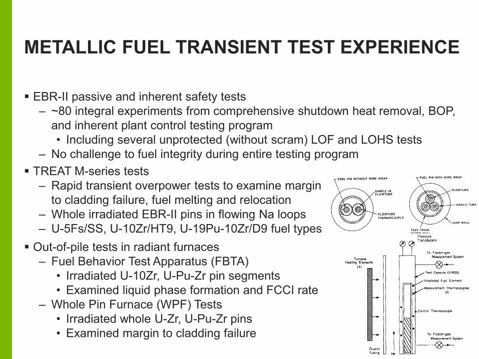
METALLIC FUEL TRANSIENT TEST EXPERIENCE
EBR-II passive and inherent safety tests– ~80 integral experiments from comprehensive shutdown heat removal, BOP,
and inherent plant control testing program• Including several unprotected (without scram) LOF and LOHS tests
– No challenge to fuel integrity during entire testing program TREAT M-series tests
– Rapid transient overpower tests to examine margin to cladding failure, fuel melting and relocation
– Whole irradiated EBR-II pins in flowing Na loops– U-5Fs/SS, U-10Zr/HT9, U-19Pu-10Zr/D9 fuel types
Out-of-pile tests in radiant furnaces– Fuel Behavior Test Apparatus (FBTA)
• Irradiated U-10Zr, U-Pu-Zr pin segments• Examined liquid phase formation and FCCI rate
– Whole Pin Furnace (WPF) Tests• Irradiated whole U-Zr, U-Pu-Zr pins• Examined margin to cladding failure

BACKUP PAGES
ACRONYMS
AFR-100: Advanced Fast Reactor (100 MWe) ALMR: Advanced Liquid Metal Reactor program BU: Burnup CRBR: Clinch River Breeder Reactor EBR: Experimental Breeder Reactor FBTA: Fuel Behavior Test Apparatus FCCI: Fuel-Cladding Chemical Interaction FCMI: Fuel-Cladding Mechanical Interaction FFTF: Fast Flux Test Facility FR: Fast Reactor IFR: Integral Fast Reactor program LWR: Light Water Reactor MOX: Mixed-OXide fuel form PWR: Pressurized Water Reactor SFR: Sodium-cooled Fast Reactor TREAT: TRansient REactor Test facility WPF: Whole Pin Furnace
FUEL PIN DESIGN CONSIDERATIONS
Burnup is defined in terms of energy yield (MWd/kg) or as the fraction of heavy atoms fissioned (atom-% burned) Creep is time-dependent strain under applied stress over a period of time Most fission products lodge within both oxide and metal fuel matrix and
contribute to overall volumetric increase known as fission product swelling– But not all the fission product gases remain confined within the fuel
• Some can diffuse to the grain boundaries and escape to the pin plenum via interconnected porosity and cracks
– Net swelling of the fuel is derived from the balance between fission gas retention vs. its release from the fuel into the fuel cladding gap and plenum
– Grain structure, porosity distribution, temperature, and temperature gradients are important factors influencing swelling
– Released fission gas pressurizes the fuel pin and applies stress to cladding• Could result in cladding liftoff concern for oxide fuel, but not metallic fuel due to
presence of bond sodium inside the cladding Material mechanical properties such as hardness, yield, and ultimate strength
are less important parameters in fuel selection
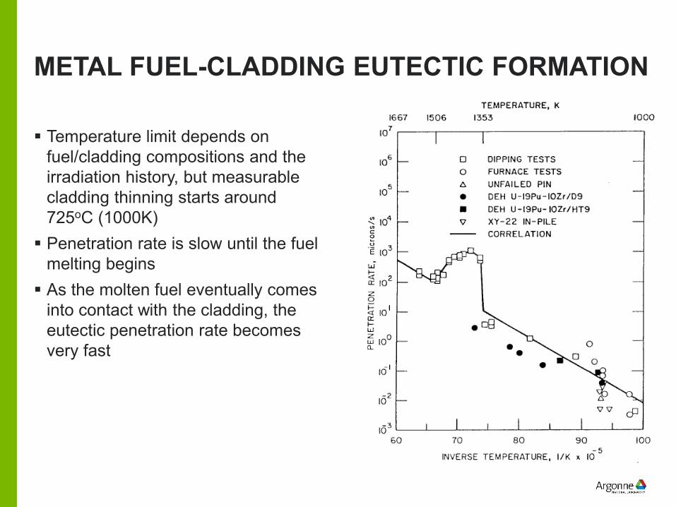
METAL FUEL-CLADDING EUTECTIC FORMATION
Temperature limit depends on fuel/cladding compositions and the irradiation history, but measurable cladding thinning starts around 725oC (1000K) Penetration rate is slow until the fuel
melting begins As the molten fuel eventually comes
into contact with the cladding, the eutectic penetration rate becomes very fast
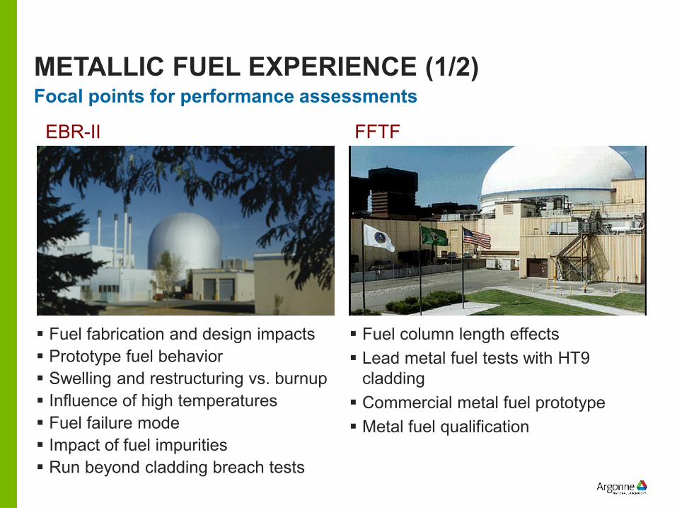
Focal points for performance assessments
Fuel fabrication and design impacts Prototype fuel behavior Swelling and restructuring vs. burnup Influence of high temperatures Fuel failure mode Impact of fuel impurities Run beyond cladding breach tests
Fuel column length effects Lead metal fuel tests with HT9
cladding Commercial metal fuel prototype Metal fuel qualification
METALLIC FUEL EXPERIENCE (1/2)
EBR-II FFTF
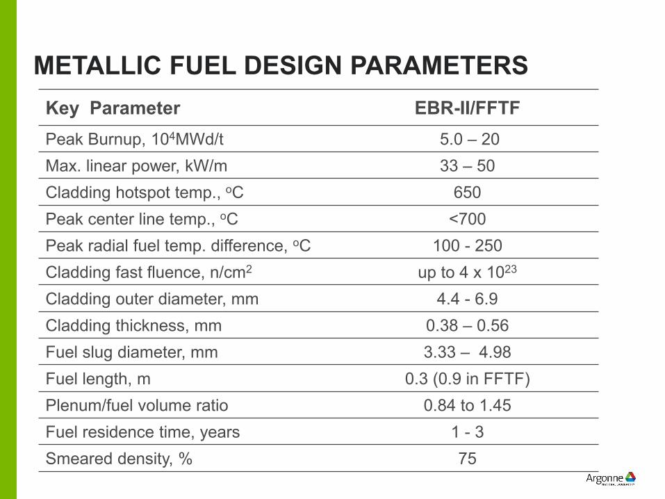
METALLIC FUEL DESIGN PARAMETERSKey Parameter EBR-II/FFTFPeak Burnup, 104MWd/t 5.0 – 20Max. linear power, kW/m 33 – 50Cladding hotspot temp., oC 650Peak center line temp., oC <700Peak radial fuel temp. difference, oC 100 - 250Cladding fast fluence, n/cm2 up to 4 x 10²³
Cladding outer diameter, mm 4.4 - 6.9Cladding thickness, mm 0.38 – 0.56Fuel slug diameter, mm 3.33 – 4.98Fuel length, m 0.3 (0.9 in FFTF)Plenum/fuel volume ratio 0.84 to 1.45Fuel residence time, years 1 - 3Smeared density, % 75
FUEL RESPONSE DURING UNPROTECTED ACCIDENTS
Some multiple-fault accident initiators can lead to fuel failures (typical cases involve unprotected accidents)– When PPS fails to scram the reactor, key early measure is to maintain the
coolant temperature below its boiling point– Net negative reactivity feedback eventually brings the reactor power into
equilibrium with the available heat rejection rate as the system approaches an asymptotic temperature distribution
– In the long term, goal is to keep the asymptotic cladding, vessel, support structure temperatures below creep limits
Avoiding core damage therefore depends on:– Providing sufficient negative reactivity feedback to overcome the initial power-
to-cooling mismatch, and – Reducing the reactivity feedback components (mainly Doppler) that resist the
return of the system to equilibrium
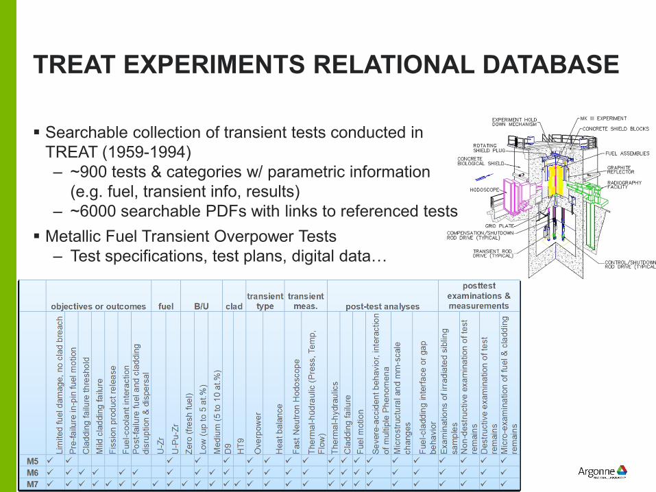
TREAT EXPERIMENTS RELATIONAL DATABASE
Searchable collection of transient tests conducted in TREAT (1959-1994)– ~900 tests & categories w/ parametric information
(e.g. fuel, transient info, results)– ~6000 searchable PDFs with links to referenced tests
Metallic Fuel Transient Overpower Tests– Test specifications, test plans, digital data…
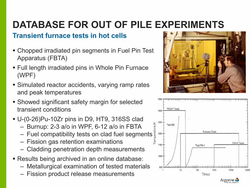
DATABASE FOR OUT OF PILE EXPERIMENTS
Chopped irradiated pin segments in Fuel Pin Test Apparatus (FBTA) Full length irradiated pins in Whole Pin Furnace
(WPF) Simulated reactor accidents, varying ramp rates
and peak temperatures Showed significant safety margin for selected
transient conditions U-(0-26)Pu-10Zr pins in D9, HT9, 316SS clad
– Burnup: 2-3 a/o in WPF, 6-12 a/o in FBTA– Fuel compatibility tests on clad fuel segments– Fission gas retention examinations– Cladding penetration depth measurements
Results being archived in an online database:– Metallurgical examination of tested materials– Fission product release measurements
Transient furnace tests in hot cells